dsp -4000 series - fluke - fluke networks · pdf filedsp-4000 series cableanalyzer ... 3...
TRANSCRIPT

DSP-4000 SeriesCableAnalyzer
Getting Started Guide
July 2001, Rev. 1, 5/03© 2001-2003 Fluke Corporation. All rights reserved. Printed in USA.All product names are trademarks of their respective companies.

Accessing the Users ManualThe DSP-4000 Series Users Manual is available on the DSP-4000 SeriesManual CD included with your test tool.
Contacting Fluke NetworksVisit the Fluke Networks web site at www.flukenetworks.com. Sendemail to [email protected].
To order accessories or get the location of the nearest Fluke Networksdistributor or service center, call:
• USA: 1-888-99-FLUKE (1-888-993-5853)
• Canada: 1-800-363-5853• Europe: +44 1923 281 300• Beijing: 010-65123435
• Japan: +81-3-3434-0181• Singapore: +65-6738-5655• Anywhere in the world: +1-425-446-4519
For operating assistance in the USA, call 1-800-283-5853.
i
Table of Contents
Title Page
Introduction.................................................................................................................... 1Registration.................................................................................................................... 1Standard Accessories.................................................................................................... 2Safety and Operational Information ............................................................................... 3Main Unit Features ........................................................................................................ 6Remote Features ........................................................................................................... 9Permanent Link Interface Adapters (DSP-4000PL/4300) ............................................. 12Setting Up the Test Tool ................................................................................................ 13
Powering the Test Tool ............................................................................................. 13Turning On the Test Tool .......................................................................................... 14Selecting a Language ............................................................................................... 14Quick Configuration .................................................................................................. 14Using the Link Interface Adapters ............................................................................. 16Checking the Memory ............................................................................................... 17Formatting the Memory Card (DSP-4100/4300) ....................................................... 17

ii
Setting Up Cable IDs ................................................................................................. 17Auto Increment ..................................................................................................... 17Auto Sequence ..................................................................................................... 17Selecting a List of Downloaded IDs (DSP-4300) .................................................. 18
Testing Cabling .............................................................................................................. 18Diagnosing Cabling Problems ........................................................................................ 18Saving Autotest Results ................................................................................................. 19
DSP-4000.................................................................................................................. 19DSP-4100/4300......................................................................................................... 19
Calibrating the Test Tool ................................................................................................ 19Getting Software Upgrades ............................................................................................ 19
1
DSP-4000 Series CableAnalyzers
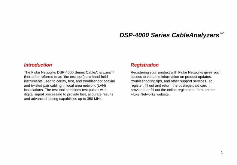
IntroductionThe Fluke Networks DSP-4000 Series CableAnalyzers™(hereafter referred to as “the test tool”) are hand-heldinstruments used to certify, test, and troubleshoot coaxialand twisted pair cabling in local area network (LAN)installations. The test tool combines test pulses withdigital signal processing to provide fast, accurate resultsand advanced testing capabilities up to 350 MHz.
RegistrationRegistering your product with Fluke Networks gives youaccess to valuable information on product updates,troubleshooting tips, and other support services. Toregister, fill out and return the postage-paid cardprovided, or fill out the online registration form on theFluke Networks website.

DSP-4000 SeriesGetting Started Guide
2
Standard AccessoriesA DSP-4000 Series test tool comes with the followingaccessories. If the test tool is damaged or something ismissing, contact the place of purchase immediately.
• 1 DSP-4000SR, DSP-4100SR, or DSP-4300SRremote unit
• The following link interface adapters:
◊ With the DSP-4000 and DSP-4100: 2DSP-LIA011 Basic Link Adapters for Cat 5E and2 DSP-LIA012 Channel Adapters for Cat 6
◊ With the DSP-4000PL: 2 DSP-LIA101Permanent Link Adapters for Cat 6 and 2DSP-LIA012 Channel Adapters for Cat 6
◊ With the DSP-4300: 2 DSP-LIA101 PermanentLink Adapters for Cat 6, 1 DSP-LIA012 ChannelAdapter for Cat 6, and 1 DSP-LIA013Channel/Traffic Adapter for Cat 6
• 2 AC adapter/chargers 120 V (US only) or universaladapter/chargers and line cords (outside NorthAmerica)
• 1 Memory card reader (DSP-4100, DSP-4300)
• 1 16 MB memory card (DSP-4100, DSP-4300)
• 1 Memory card carrying case (DSP-4100, DSP-4300)
• 2 NiMH battery packs (installed)
• 2 Headsets
• 1 DSP-4000 Calibration Module
• 1 RJ45 to BNC adapter
• 1 PC serial interface (EIA-232C) cable
• 2 Carrying straps
• 1 LinkWare software CD
• 1 DSP-4000 Series Manual CD (includes completeusers manual)
• 1 DSP-4000 Series Getting Started Guide
• 1 Warranty registration card
• 1 Soft carrying case
If you purchased optional Fiber Test Adapters, refer to theFiber Test Adapter users manual for a list of fiberaccessories.
Safety and Operational Information
3
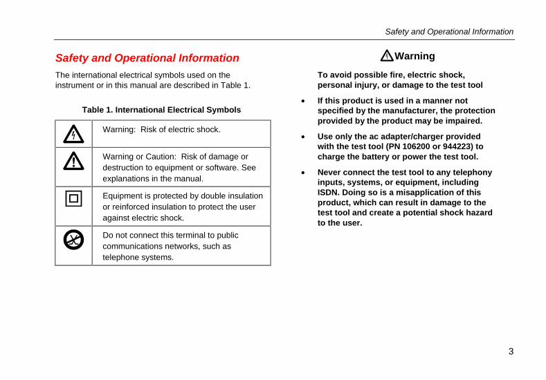
Safety and Operational InformationThe international electrical symbols used on theinstrument or in this manual are described in Table 1.
Table 1. International Electrical Symbols
Warning: Risk of electric shock.
Warning or Caution: Risk of damage ordestruction to equipment or software. Seeexplanations in the manual.
Equipment is protected by double insulationor reinforced insulation to protect the useragainst electric shock.
Do not connect this terminal to publiccommunications networks, such astelephone systems.
Warning
To avoid possible fire, electric shock,personal injury, or damage to the test tool
• If this product is used in a manner notspecified by the manufacturer, the protectionprovided by the product may be impaired.
• Use only the ac adapter/charger providedwith the test tool (PN 106200 or 944223) tocharge the battery or power the test tool.
• Never connect the test tool to any telephonyinputs, systems, or equipment, includingISDN. Doing so is a misapplication of thisproduct, which can result in damage to thetest tool and create a potential shock hazardto the user.
DSP-4000 SeriesGetting Started Guide
4
• Never connect the CABLE TEST input to anyLAN inputs, systems, or equipment. Doing sois a misapplication of this product, which canresult in damage to the test tool and create apotential shock hazard to the user.
• Always turn on the test tool beforeconnecting it to a cable. Turning the test toolon activates the tool’s input protectioncircuitry.
• When servicing the test tool, use onlyspecified replacement parts.
• Do not use the test tool if it operatesabnormally. Protection may be impaired.
• Do not use the test tool if it is damaged.Inspect the test tool before use.
Caution
To avoid disrupting network operation and toensure maximum accuracy of test results
• Except when monitoring network activity,never connect the test tool to an activenetwork. Doing so may disrupt networkoperation.
• Never attempt to insert any connector otherthan an RJ45 connector into the RJ45 jack.Inserting other connectors, such as RJ11(telephone) connectors, can permanentlydamage the jack.
• Never attempt to send data from a PC to thetest tool while running a cable test. Doing somight cause erroneous test results.

Safety and Operational Information
5
• Never operate portable transmitting devicesduring a cable test. Doing so might causeerroneous test results.
• When using the channel/traffic link interfaceadapter (DSP-LIA013), never run tests withcables connected to both the cable jack andthe monitor jack. Doing so might causeerroneous test results.
• To ensure maximum accuracy of test results,perform the self-calibration procedure asdescribed in “ Calibrating the Test Tool” inChapter 6 of the Users Manual every 30 days.
• To avoid false test results, recharge thebattery as soon as the low battery messageappears.
• If your test tool includes the DSP-LIA101Permanent Link Adapters, see “ PermanentLink Interface Adapters” for importanthandling information.

DSP-4000 SeriesGetting Started Guide
6
Main Unit Features
OFF
MONITORSETUP
SPECIALFUNCTIONS
SINGLETEST
AUTOTEST
TALK
EXIT
ENTERTEST SAVE
1 2 3 4
FAULTINFO
DSP-4100/4300 Side Plate
DSP-4000 Side Plate
54
32
1
10
11
8
9
7
613
18
1714
15
16
12
ank05f.eps
Figure 1. Main Unit Features
Main Unit Features
7
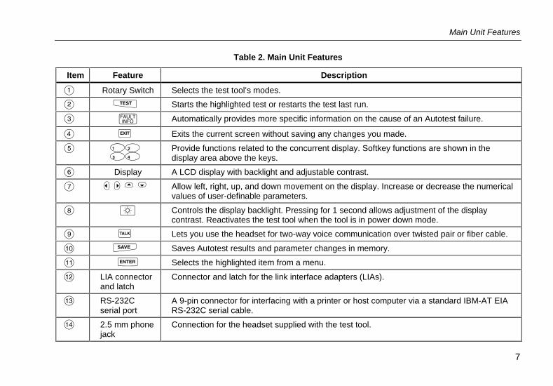
Table 2. Main Unit Features
Item Feature Description
� Rotary Switch Selects the test tool’s modes.
� � Starts the highlighted test or restarts the test last run.
� � Automatically provides more specific information on the cause of an Autotest failure.
� � Exits the current screen without saving any changes you made.
� ����
Provide functions related to the concurrent display. Softkey functions are shown in thedisplay area above the keys.
� Display A LCD display with backlight and adjustable contrast.
� ����� Allow left, right, up, and down movement on the display. Increase or decrease the numericalvalues of user-definable parameters.
� � Controls the display backlight. Pressing for 1 second allows adjustment of the displaycontrast. Reactivates the test tool when the tool is in power down mode.
Lets you use the headset for two-way voice communication over twisted pair or fiber cable.
� Saves Autotest results and parameter changes in memory.
� � Selects the highlighted item from a menu.
� LIA connectorand latch
Connector and latch for the link interface adapters (LIAs).
RS-232Cserial port
A 9-pin connector for interfacing with a printer or host computer via a standard IBM-AT EIARS-232C serial cable.
� 2.5 mm phonejack
Connection for the headset supplied with the test tool.

DSP-4000 SeriesGetting Started Guide
8
Table 2. Main Unit Features (cont.)
Item Feature Description
LED off,unit turned off
Battery is not charging.The charger is not plugged in.
LED off,unit turned on
Battery is not charging.The charger is not plugged in or the test tool isrunning a test. When the test is finished, chargingresumes unless the battery is already charged(>80%).
LED flashing red Fast charge pending.Charging is beginning. This state may last for severalminutes until fast charging begins.
LED steady red Fast charge.The unit stays in fast charge mode for up to 4 hours,or until either the battery is fully charged or a test isinitiated.
� AC power indicator
LED steadygreen
Charge complete.Fast charge is complete. The unit enters tricklecharge mode.
� AC adapter/ charger jack Connection for the ac adapter/charger supplied with the test tool.
� Eject button (DSP-4100/4300) Button for ejecting the memory card.
� Memory card slot(DSP-4100/4300)
Slot for the memory card used for saving Autotest results on a DSP-4100 orDSP-4300 test tool.

Remote Features
9
Remote Features
ON
OFF
PASS
TESTING
TALKING
FAIL
LOW BATTERY
TALK
1
2
3
5
678
910
11
12
4
ank06f.eps
Figure 2. Remote Features

DSP-4000 SeriesGetting Started Guide
10
Table 3. Remote Connectors and Features
Item Feature Description
� RS-232C serial port A DB9P connector for loading software updates.
� 2.5 mm phone jack Connection for the headset supplied with the test tool.
� AC adapter/charger jack
Connection for the ac adapter/charger supplied with the test tool.
LED off,unit turned off
Battery is not charging.The charger is not plugged in.
LED off,unit turned on
Battery is not charging.The charger is not plugged in or the test tool is running a test. Whenthe test is finished, charging resumes unless the battery is alreadycharged (>80%).
LED flashing red Fast charge pending.Charging is beginning. This state may last for several minutes untilfast charging begins.
LED steady red Fast charge.The unit stays in fast charge mode for up to 4 hours, or until eitherthe battery is fully charged or a test is initiated.
� AC power indicator
LED steadygreen
Charge complete.Fast charge is complete. The unit enters trickle charge mode.
Remote Features
11
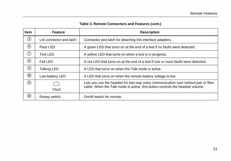
Table 3. Remote Connectors and Features (cont.)
Item Feature Description
� LIA connector and latch Connector and latch for attaching link interface adapters.
� Pass LED A green LED that turns on at the end of a test if no faults were detected.
� Test LED A yellow LED that turns on when a test is in progress.
� Fail LED A red LED that turns on at the end of a test if one or more faults were detected.
Talking LED A LED that turns on when the Talk mode is active.
Low-battery LED A LED that turns on when the remote battery voltage is low.
� �TALK
Lets you use the headset for two-way voice communication over twisted pair or fibercable. When the Talk mode is active, this button controls the headset volume.
� Rotary switch On/off switch for remote.

DSP-4000 SeriesGetting Started Guide
12
Permanent Link Interface Adapters(DSP-4000PL/4300)
Caution
To avoid damaging the adapter and to ensuremaximum accuracy of test results, neverpinch, kink, or crush the adapter’s cable.Never use the cable as a handle to pick upthe DSP test tool. Follow the handlingguidelines given in Figures 3 and 4.
For the best accuracy, keep the adapter’scable as straight as possible during testing.
To avoid latent or immediate damage due toelectrostatic discharge:
• Before handling a module or an adapter withno module attached, ground yourself whenpossible by touching a grounded, conductivesurface.
• Always remove the adapter from the DSP testtool before changing the personality module.
• Always keep a personality module attachedto the adapter cable.
• Tighten the screw snugly with your fingersonly. Do not overtighten. Doing so candamage the module or the end of the cable.
• Always store the personality module in itsoriginal, static protection bag when not inuse.
4" (10 cm)minimum bend
Storage
360˚ twist maximum
ank85f.eps
Figure 3. Permanent Link Adapter HandlingGuidelines

Setting Up the Test Tool
13
Static sensitive device
Personalitymodule
ank86f.eps
Figure 4. Changing the Personality Module
Setting Up the Test Tool
Powering the Test Tool
Before powering the test tool or remote with the NiMHbattery pack, charge the battery for about 3 hours. Tocharge the battery, connect the ac adapter/charger to thetest tool or remote and to ac line power. You can operatethe unit on ac power while the battery charges. A fully-charged battery typically lasts at least 8 hours.
To check the battery status, turn the rotary switch toSPECIAL FUNCTIONS; then select������������.
Note
The ac adapter/charger will not power the testtool when the battery pack is removed.

DSP-4000 SeriesGetting Started Guide
14
Turning On the Test Tool
To turn on the test tool, turn the rotary switch from OFF toany one of the available modes. The power-up screen,which appears for about 3 seconds, shows the software,hardware, and test standards versions for the main andremote units. (The remote information is shown only if theremote is on and connected to the main unit.)
During the power up cycle the test tool performs a selftest. If an error message appears, refer to “If the TestTool Fails” in Chapter 8 of the users manual on theDSP-4000 Series Manual CD.
Selecting a Language
The test tool displays a language selection screen if alanguage has not been selected since the tool left thefactory. Use � to select a language; then press �.You can change the selected language at any time inSETUP mode.
Quick Configuration
Table 4 describes the settings you will most likely need tochange to configure the test tool for your needs.
To access the settings, turn the rotary switch to SETUP.Use � ����� ��� and � to locate and highlighta setting; then press � to see the available choices.

Setting Up the Test Tool
15
Table 4. Quick Configuration Settings
SETUP Setting Description
Test Standardand Cable Type
Select the test standard and cable type you are using. Fiber optic cable testing requires a FlukeNetworks DSP-FTA Fiber Test Adapter or a Fluke Networks DSP-FOM (Fiber Optic Meter; comeswith the DSP-FTK).
ReportIdentification
Enter your company’s name, operators’ names, and site names. These names appear in theAutotest reports you save.
Auto Increment(cable ID setup)
Enabling this setting causes the last character of the cable ID to increment each time you save anAutotest. The Sequence selection lets you define a range of cable IDs by entering a start and endID. On a DSP-4300, the Cable ID List selection lets you select a list of IDs that was created andsaved on a memory card with LinkWare software.
Store Plot Data(DSP-4100/4300)
Enable this setting to store plot data (from tests such as attenuation, return loss, and NEXT) withAutotest results saved on a DSP-4100 or DSP-4300 test tool.
Date and Time Set the date and time and select a format for each.
Length Units Select meters or feet as the unit for length measurements.
Numeric Format Select a format (0.00 or 0,00) for display of decimal fractions.
Language Select a language for the display.
Power Line NoiseFilter Frequency
Select the frequency of the ac power in your area. The test tool filters out 50 Hz or 60 Hz noisefrom measurements.

DSP-4000 SeriesGetting Started Guide
16
Using the Link Interface Adapters
The link interface adapters provide the correct connectorsand interface circuitry for testing different types of LANcabling. The adapters also allow for upgrades when newtypes of cable are developed.
If your test tool includes the DSP-LIA101 Permanent LinkAdapters, see “Permanent Link Interface Adapters” onpage 12 for important handling information.
Optional link interface adapters that provide additionalfunctions are available from your Fluke Networks dealer.Visit the Fluke Networks website atwww.flukenetworks.com for the most recent informationon optional adapters.
Figure 5 shows how to attach a link interface adapter.Refer to Appendix A in the Users Manual for a list of testssupported by the standard link interface adapters.
Note
The test tool displays a message if you try to runa test not supported by the attached linkinterface adapter.
ank72f.eps
Figure 5. Attaching a Link Interface Adapter
Setting Up the Test Tool
17
Checking the Memory
To check the available memory space, turn the rotaryswitch to AUTOTEST; then press � ������.
Formatting the Memory Card (DSP-4100/4300)
Autotest results you save on a DSP-4100 or DSP-4300test tool are stored on a removable memory card. Toformat a memory card, insert the card into the test tool,select ������������������������ from theSPECIAL FUNCTIONS menu; then press � ������.
Setting Up Cable IDs
The cable identification (cable ID) is the name you assignto the Autotest results saved for a cable. You can createa cable ID each time you save an Autotest, or you canuse IDs generated as follows:
Auto Increment
The auto increment function generates IDs byincrementing the last alphanumeric character in the cableID. To enable this function, select ������ under������ �!��� � in SETUP.
The last character of the cable ID you enter when yousave the next Autotest will be incremented when yousave subsequent Autotests.
Auto Sequence
The auto sequence function increments letters andnumbers starting with the farthest right character, thenmoving left. Special characters (such as -, #, and spaces)and matching characters are not incremented.
To enable this function, select ��"��#� under������ �!��� � in SETUP. Press ������� ���"$ to enter a start and end ID for thesequence. When you save an Autotest, the test tooldisplays the ID list. Used IDs are preceded by a “$”.
DSP-4000 SeriesGetting Started Guide
18
Selecting a List of Downloaded IDs (DSP-4300)
On a DSP-4300 test tool you can select cable IDs fromlists created with LinkWare software and saved on amemory card. See “Getting Started” under Help on theLinkWare toolbar for details on creating ID lists.
To enable this function, select ������� �%�� under������ �!��� � in SETUP. Press �����#��� �%�� to choose a list on the memorycard. When you save an Autotest, the test tool displaysthe ID list. Used IDs are preceded by a “$”.
Testing Cabling1. Attach the appropriate link interface adapters to the
main and remote units. Turn on the remote unit.
2. Turn the rotary switch on the main unit toAUTOTEST.
3. Verify that the test standard and cable type arecorrect. You can change these settings in the SETUPmode.
4. Connect the main and remote units to the near andfar ends of the link.
5. Press � to start the Autotest.
Diagnosing Cabling ProblemsIf an Autotest fails, you can press � to see morespecific information on the cause of the failure. For mosttypes of failures, the test tool shows the distance to thefault and suggests what to check in the link.
The SINGLE TEST mode on the rotary switch allowsindividual execution of many of the tests available in theAutotest mode. Single tests help you isolate cablingfailures and quickly determine if repairs are good. SomeSingle Tests include a “Scanning” mode that runs the testcontinuously to help you identify intermittent problems.
Note
To extend battery life, connect the acadapter/charger when using the scanningfunction for more than 1 minute.

Saving Autotest Results
19
Saving Autotest ResultsTo save the Autotest results, press �. Depending onwhich cable ID function is enabled in SETUP, you caneither create a cable ID or select an ID from a pre-configured list. Press � again after creating orselecting an ID.
DSP-4000
A DSP-4000 test tool can store the results of 500 or moreAutotests, depending on the test standard used. Resultsare stored in text-based format.
DSP-4100/4300
A DSP-4100 or DSP-4300 test tool with STORE PLOTDATA enabled can store at least 250 Autotests ingraphical format on a 16 MB memory card, depending onthe standard used.
If no memory card is present in a DSP-4300 test tool, testresults are saved to internal memory. Later, when youinsert a memory card, the test tool lets you choosewhether or not to copy the saved results from internalmemory to the memory card.
Note for Model DSP-4300
To avoid confusion regarding the contents of theinternal memory, save test results on aremovable memory card whenever possible.
Calibrating the Test ToolTo ensure maximum accuracy of test results, perform theself-calibration every 30 days. Select ��������������� from the SPECIAL FUNCTIONS menu.See Chapter 6 of the Users Manual for details.
Fluke Networks recommends factory calibration once ayear to ensure that the test tool meets or exceeds thepublished accuracy specifications. To return a unit toFluke Networks for calibration, call an authorized FlukeNetworks Service Center for return instructions.
Getting Software UpgradesKeeping your test tool’s software current gives youaccess to new features and the latest test standards.Software upgrades are available for free on the FlukeNetworks website. See the online documentation inLinkWare for information on installing upgrades.
DSP-4000 SeriesGetting Started Guide
20
LIMITED WARRANTY & LIMITATION OF LIABILITYEach Fluke Networks product is warranted to be free from defects in material and workmanship under normal use and service. The warrantyperiod is one year and begins on the date of purchase. Parts, accessories, product repairs and services are warranted for 90 days. Thiswarranty extends only to the original buyer or end-user customer of a Fluke Networks authorized reseller, and does not apply to disposablebatteries, cable connector tabs, cable insulation-displacement connectors, or to any product which, in Fluke Networks’ opinion, has beenmisused, altered, neglected, contaminated, or damaged by accident or abnormal conditions of operation or handling. Fluke Networkswarrants that software will operate substantially in accordance with its functional specifications for 90 days and that it has been properlyrecorded on non-defective media. Fluke Networks does not warrant that software will be error free or operate without interruption.Fluke Networks authorized resellers shall extend this warranty on new and unused products to end-user customers only but have noauthority to extend a greater or different warranty on behalf of Fluke Networks. Warranty support is available only if product is purchasedthrough a Fluke Networks authorized sales outlet or Buyer has paid the applicable international price. Fluke Networks reserves the right toinvoice Buyer for importation costs of repair/replacement parts when product purchased in one country is submitted for repair in anothercountry.Fluke Networks’ warranty obligation is limited, at Fluke Networks’ option, to refund of the purchase price, free of charge repair, orreplacement of a defective product which is returned to a Fluke Networks authorized service center within the warranty period.To obtain warranty service, contact your nearest Fluke Networks authorized service center to obtain return authorization information, thensend the product to that service center, with a description of the difficulty, postage and insurance prepaid (FOB Destination). Fluke Networksassumes no risk for damage in transit. Following warranty repair, the product will be returned to Buyer, transportation prepaid (FOBDestination). If Fluke Networks determines that failure was caused by neglect, misuse, contamination, alteration, accident or abnormalcondition of operation or handling, or normal wear and tear of mechanical components, Fluke Networks will provide an estimate of repaircosts and obtain authorization before commencing the work. Following repair, the product will be returned to the Buyer transportationprepaid and the Buyer will be billed for the repair and return transportation charges (FOB Shipping Point).THIS WARRANTY IS BUYER’S SOLE AND EXCLUSIVE REMEDY AND IS IN LIEU OF ALL OTHER WARRANTIES, EXPRESS ORIMPLIED, INCLUDING BUT NOT LIMITED TO ANY IMPLIED WARRANTY OF MERCHANTABILITY OR FITNESS FOR A PARTICULARPURPOSE. FLUKE NETWORKS SHALL NOT BE LIABLE FOR ANY SPECIAL, INDIRECT, INCIDENTAL OR CONSEQUENTIALDAMAGES OR LOSSES, INCLUDING LOSS OF DATA, ARISING FROM ANY CAUSE OR THEORY.Since some countries or states do not allow limitation of the term of an implied warranty, or exclusion or limitation of incidental orconsequential damages, the limitations and exclusions of this warranty may not apply to every buyer. If any provision of this Warranty is heldinvalid or unenforceable by a court or other decision-maker of competent jurisdiction, such holding will not affect the validity or enforceabilityof any other provision.
Fluke NetworksPO Box 777Everett, WA 98206-0777USA
6-01