dslc-2™ digital synchronizer and load control · product specification 37493e dslc-2™ digital...
TRANSCRIPT
Product Specification
37493E
DSLC-2™
Digital Synchronizer and Load Control
Applications for up to
32 generators with 16 mains/tie breakers
Complex applications with up to 8 bus segments
Redundant load and VAR sharing over Ether-net
Four communication ports: 2 Ethernet, RS-485 & RS-232 ports.
The “system update” feature allows for remov-ing or adding generator sets in the system.
Automatic generator soft loading and unloading for bump-less load transfer
Isochronous load shar-ing with other DSLC- 2 equipped sets
Base load and process control modes
VAR or Power Factor control
Dead bus closing
PLC & DCS compatible
The DSLC-2 hardware is configurable for multiple speed controls, voltage regulators, and potential transformer configura-tions
Application range up to 999.999,9 MW
UL/cUL & CE Listed
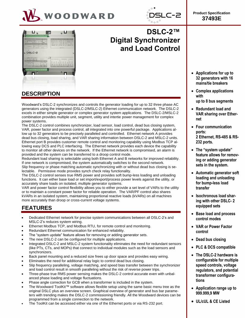
DESCRIPTION
Woodward’s DSLC-2 synchronizes and controls the generator loading for up to 32 three phase AC generators using the integrated (DSLC-2/MSLC-2) Ethernet communication network. The DSLC-2 excels in either simple generator or complex generator system applications. The DSLC-2/MSLC-2 combination provides multiple unit, segment, utility and intertie power management for complex power systems. The DSLC-2 control combines synchronizer, load sensor, load control, dead bus closing system, VAR, power factor and process control, all integrated into one powerful package. Applications al-low up to 32 generators to be precisely paralleled and controlled. Ethernet network A provides dead bus closing, load sharing, and VAR sharing information between DSLC-2 and MSLC-2 units. Ethernet port B provides customer remote control and monitoring capability using Modbus TCP al-lowing easy DCS and PLC interfacing. The Ethernet network provides each device the capability to monitor all other devices on the network. If the Ethernet network is compromised, an alarm is provided and the system can be transferred to a droop control mode. Redundant load sharing is selectable using both Ethernet A and B networks for improved reliability. If one network is compromised, the system automatically switches to the second network. Slip frequency or phase matching automatic synchronizing with or without dead bus closing is se-lectable. Permissive mode provides synch check relay functionality. The DSLC-2 control senses true RMS power and provides soft bump-less loading and unloading functions. It can either base load or set import/export/process power levels against the utility, or accurately share loads on isolated, multiple generator systems. VAR and power factor control flexibility allows you to either provide a set level of VARs to the utility or to maintain a constant power factor for reliable operation. The VAR/PF control also shares kVARs in an isolated system, maintaining proportional reactive loads (kVARs) on all machines more accurately than droop or cross-current voltage systems.
FEATURES
Dedicated Ethernet network for precise system communications between all DSLC-2’s and MSLC-2’s reduces system wiring.
Ethernet Modbus TCP, and Modbus RTU, for remote control and monitoring.
Redundant Ethernet communication for enhanced reliability.
The “system update” feature allows for removing or adding generator sets.
The new DSLC-2 can be configured for multiple applications.
Integrated DSLC-2 and MSLC-2 system functionality eliminates the need for redundant sensors (like PTs, CTs, and MOPs) that connect to individual modules such as the load sensors and synchronizers.
Back panel mounting and a reduced size frees up door space and provides easy wiring.
Eliminates the need for additional relay logic to control dead bus closing.
Slip frequency paralleling, voltage matching, and speed bias transfer between the synchronizer and load control result in smooth paralleling without the risk of reverse power trips.
Three-phase true RMS power sensing makes the DSLC-2 control accurate even with unbal-anced phase loading and voltage fluctuations.
Phase angle correction for GCB when a transformer is included in the system.
The Woodward ToolKit™ software allows flexible setup using the same basic menu tree as the original DSLC plus an overview screen. Graphical overview of generator and bus bar parame-ters with trending makes the DSLC-2 commissioning friendly. All the Woodward devices can be programmed from a single connection to the network.
The ToolKit can be accessed either via one of the Ethernet ports or via RS-232 port.
SPECIFICATIONS
Power supply .......................................................... 12/24 Vdc (8 to 40 Vdc) Intrinsic consumption .................................................................. max. 15 W Ambient temperature (operation) ................... -40°C to 70°C / -40 to 158°F Ambient temperature (storage) ...................... -40°C to 85°C / -40 to 185°F Ambient humidity....................................................... 95%, non-condensing Voltage ................................................................................................ ( /) 120 Vac [1] Rated (Vrated) ............................................ 69/120 Vac Max. value (Vmax) ............................................ 86/150 Vac Rated voltage phase - ground ................................................. 150 Vac Rated surge volt. (Vsurge) .................................................... 2.5 kV and 480 Vac [4] Rated (Vrated) .......................................... 277/480 Vac Max. value (Vmax) .......................................... 346/600 Vac Rated voltage phase - ground ................................................. 300 Vac Rated surge volt. (Vsurge) .................................................... 4.0 kV Accuracy ....................................................................................... Class 0.5 Measurable alternator windings ........................... 3p-3w, 3p-4w, 3p-4w OD Setting range ..................... primary .................................50 to 650,000 Vac Linear measuring range .............................................................. 1.25×Vrated Measuring frequency............................................... 50/60 Hz (40 to 85 Hz)
High Impedance Input; Resistance per path ....... [1] 0.498 M, [4] 2.0 M Max. power consumption per path ................................................ < 0.15 W Current (galvanically isolated) Rated (Irated) ............. [1] ../1 A or [5] ../5 A Linear measuring range ........................................................ Igen = 3.0×Irated Imains/ground = 1.5×Irated Setting range .......................................................................... 1 to 32,000 A Burden .......................................................................................... < 0.15 VA Rated short-time current (1 s) .................................[1] 50×Irated, [5] 10×Irated Accuracy ....................................................................................... Class 0.5
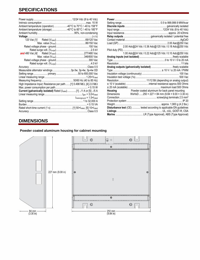
Power .............................................................................................................. Setting range.......................................................... 0.5 to 999,999.9 MW/kvar Discrete inputs .............................................................. galvanically isolated Input range ................................................................. 12/24 Vdc (8 to 40 Vdc) Input resistance.................................................................. approx. 20 kOhms Relay outputs .........................................galvanically isolated / potential free Contact material ................................................................................... AgCdO Load (GP) ........................................................................ 2.00 Aac@250 Vac 2.00 Adc@24 Vdc / 0.36 Adc@125 Vdc / 0.18 Adc@250 Vdc Pilot duty (PD) .................................................................................................. 1.00 Adc@24 Vdc / 0.22 Adc@125 Vdc / 0.10 Adc@250 Vdc Analog inputs (not isolated) ..................................................freely scalable Type .............................................................................. 0 to 10 V / 0 to 20 mA Resolution ............................................................................................. 11 bits Analog outputs (galvanically isolated) .................................freely scalable Type ......................................................................... ± 10 V / ± 20 mA / PWM Insulation voltage (continuously) ....................................................... 100 Vac Insulation test voltage (1s) ................................................................. 500 Vac Resolution ......................................... 11/12 Bit (depending on analog output) ± 10 V (scalable) ..................................internal resistance approx.500 Ohms ± 20 mA (scalable) ................................................ maximum load 500 Ohms Housing Powder coated aluminum for back panel mounting Dimensions WxHxD ...... 250 × 227 × 84 mm (9.84 × 9.00 × 3.30 in) Connection ....................................................... screw/plug terminals 2.5 mm² Protection system ................................................................................... IP 20 Weight ..................................................................... approx. 1,900 g (4.2 lbs.) Disturbance test (CE) ............ tested according to applicable EN guidelines Listings .................................................................... UL, cUL, GOST-R, CSA Marine ......................................... LR (Type Approval), ABS (Type Approval)
DIMENSIONS
Powder coated aluminum housing for cabinet mounting
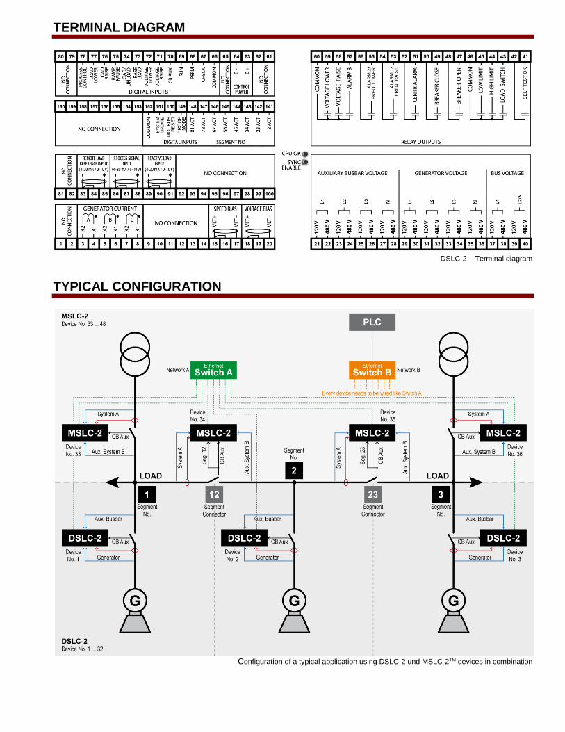
TERMINAL DIAGRAM
DSLC-2 – Terminal diagram
TYPICAL CONFIGURATION
Configuration of a typical application using DSLC-2 und MSLC-2TM devices in combination
CONTACT
North & Central America
Tel.: +1 970 962 7331
South America
Tel.: +55 19 3708 4800 [email protected]
Europe
Tel. Stuttgart: +49 711 78954 510
Tel. Kempen: +49 2152 145 331 [email protected]
Middle East & Africa
Tel.: +971 2 6275185 [email protected]
Russia
Tel.: +7 812 319 3007 [email protected]
China
Tel.: +86 512 8818 5515 [email protected]
India
Tel.: +91 124 4399 500 [email protected]
ASEAN & Oceania
Tel.: +49 711 78954 510 [email protected]
www.woodward.com Subject to alterations, errors excepted. Subject to technical modifications.
This document is distributed for in-formational purposes only. It is not to be construed as creating or be-coming part of any Woodward Com-pany contractual or warranty obliga-tion unless expressly stated in a written sales contract.
We appreciate your comments about the content of our publica-tions. Please send comments includ-ing the document number below to [email protected]
© Woodward All Rights Reserved
37493E - 2015/02/Stuttgart
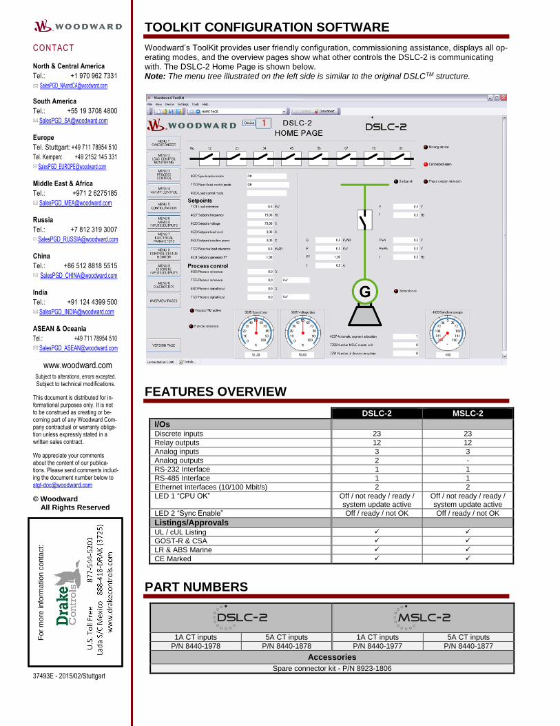
TOOLKIT CONFIGURATION SOFTWARE
Woodward’s ToolKit provides user friendly configuration, commissioning assistance, displays all op-erating modes, and the overview pages show what other controls the DSLC-2 is communicating with. The DSLC-2 Home Page is shown below. Note: The menu tree illustrated on the left side is similar to the original DSLCTM structure.
FEATURES OVERVIEW
DSLC-2 MSLC-2
I/Os Discrete inputs 23 23
Relay outputs 12 12
Analog inputs 3 3
Analog outputs 2 -
RS-232 Interface 1 1
RS-485 Interface 1 1
Ethernet Interfaces (10/100 Mbit/s) 2 2
LED 1 “CPU OK” Off / not ready / ready / system update active
Off / not ready / ready / system update active
LED 2 “Sync Enable” Off / ready / not OK Off / ready / not OK
Listings/Approvals UL / cUL Listing
GOST-R & CSA
LR & ABS Marine
CE Marked
PART NUMBERS
1A CT inputs 5A CT inputs 1A CT inputs 5A CT inputs
P/N 8440-1978 P/N 8440-1878 P/N 8440-1977 P/N 8440-1877
Accessories
Spare connector kit - P/N 8923-1806
Fo
r m
ore
info
rma
tio
n c
onta
ct: