dsk 4 02 ХХ - kids and fitnessfitness-kids.com/common/docs/dsk 4_02_xx.pdf · importer: “kids...
TRANSCRIPT
CHILDREN’S HOME PLAYGROUND SET series name:
SPIDER-WALL
Operating Manual DSK 4.02.ХХ RE
MANUFACTURER: ZAO “Zavod igrovogo sportivnogo oborudovaniya” Montazhnyi proezd, 6, Cheboksary, Chuvashskaya Republic, Russian Federation 428037
IMPORTER: “KIDS AND FITNESS INC.”, 140 RIDGEWOOD AVE. SUIT 415, PARAMUS, NEW JERSEY 07652,
+1(201)477.05.02, [email protected]

11.03.2010г 2
WARNING! Please follow all these Safe-ty, Assembly and Mainten-
ance Instructions. Failure to do so could result in serious or fatal injury. If
you have any questions about the safe use of your
purchase, contact “Kids and Fitness Inc.” at
+1(201)477.05.02
NOTICE Not for public use - for
residential use only. Intended for use by
not more than 1 child.
NOTE TO INSTALLER You must assemble this product in accordance with the assembly instructions in this Operating Manual. After assembly is complete, please give this Operating Manual, as well as any tools provided, to the owner of the product. Please re-
mind the owner to review the Safety and Maintenance Instructions.
Thank you for purchasing Children’s home
playground set series name “SPIDER-WALL” (hereinafter referred as PLAYGROUND SET)
from “Kids and Fitness Inc.”
PLEASE... Keep a copy of this Operating Manual and your order with your important docu-ments during all the time of using the PLAYGROUND SET. They should not be
discarded as they all contain important information. You will need to refer to these items if you contact “Kids and Fitness Inc.” about your PLAYGROUND SET. Should you transfer your “Kids and Fitness Inc.” products to another person,
please be sure the new owner receives all these documents.
Table of content: 1. Safety Instructions -3 5. Operation instruction -122. Introduction -4 6. Transportation and storing -133. Assembly Instruction -7 7. Utilization -134. Maintenance instruction -12 8. Warranty -13

11.03.2010г 3
SAFETY INSTRUCTIONS Please thoroughly read this Operating Manual (hereinafter referred as “OM”) to become familiar with the assembly, order, safe use, maintenance, transportation and storage of the PLAYGROUND SET. Observing the following statements and warnings reduces the likelihood of serious or fatal injury.
Assembling, disassembling and installation of the PLAYGROUND SET must be done by not less than 2 adults after careful studying the OM.
Maximum fall height for the product is from 7 to 10 ft. The PLAYGROUND SET is designed for the children of age group 6-14 years old.
In order to avoid serious or fatal injury IT IS PROHIBITED:
-attendance and participation of children in assembling, disassembling and installation of the PLAYGROUND SET; -to adjust PLAYGROUND SET by the children; -to use PLAYGROUND SET by the children without adult supervision; WARNING
CHILDREN SHOULD USE THE PLAYGROUND SET UNDER ADULT SUPERVISION
-to use PLAYGROUND SET by the children without using appropriate shock-absorbing protective surfacing materials (for your reference see extract from the sec-tion 4 of the Consumer Products Safety Commission’s “Outdoor home playground safety handbook” in Appen-dix 1.);
WARNING USING THE PLAYGROUND SET WITHOUT
APPROPRIATE SHOCK-ABSORBING PROTECTIVE SURFACING MATERIALS MAY RESULT IN SERIOUS
INJURY OR DEATH FROM FALLS - to use PLAYGROUND SET by more than 1 child (weight less than 220 lbs) simultaneously. This OM is applicable for the following models and design of PLAYGROUND SETs: DSK 4.02.ХХ – design 4.02.01, DSK 4.02.03, DSK 4.02.04. Safety of the PLAYGROUND SET if verified by:
• TÜV NORD – European Union inspection and testing organizations (www.tuv-nord.com), Certificate No. 44 321 07 343073 from 9th of March 2007.
• State Standard of Russian Federation, Certificate No. “ROSS RU.АЕ83. В24173 from 20th of October 2009”;
TEACH YOUR CHILD SAFE PLAY: Not to walk close to, in front of, behind, or between moving items. Not to twist the swing ropes, or swing empty swing ropes, or loop them over the top support bar, since this
may reduce the strength of the rope. Not to swing sideways into the path of adjacent swings. Not to use the equipment in a manner other than that for which it is intended. Not to get off the equipment while it is in motion. Not to climb or swing with wet hands or when the equipment is wet (for ex. after moist cleaning). Not to stand in the rings. Not to use hammers, saws, nails, or wrenches on the equipment. Not to climb on top of the swing support. Not to attach to the playground equipment any item that is not specifically designed for use with the equip-
ment, such as (but not limited to) jump ropes, clotheslines, pet leashes, cables, and chains. These may be-come strangulation hazards.
To watch for other children while swinging or playing near the equipment. IN ADDITION, ADULTS MUST:
Limit climbing and swinging heights to each child’s ability. Dress children appropriately for play. Use wellfitting
shoes that do not have slippery soles. Avoid pon-chos, scarves, hoods, loose-fitting clothing, neck-ties, and any clothing with a drawstring. Serious in-jury could result should any part of the children’s clothing become entangled in the equipment.
WARNING STRANGULATION HAZARD!
Children have died when drawstrings on their clothing caught on slides or other playground equipment. Remove ponchos, scarves, hoods,
loose-fitting clothing, neckties, and any clothing with a drawstring before children play on the
PLAYGROUND SET Verify that suspended climbing ropes are secured and cannot be looped back on itself.

11.03.2010г 4
Remember that children are inventive. When they develop games that are unsafe, be alert and change the rules.
INTRODUCTION 1. DESTINATION OF PLAYGROUND SET The PLAYGROUND SET is designed for play exercises inside households. It is not intended for use in places of public assembly such as schools, parks, condominiums, churches and temples, and child care centers 2. SPECIFICATIONS
Table 1
Overall dimension , in
Length, in 6’5,8” Width, in 3’1,6”
Height, in from 7'6,5” till 9’10,8” (from 6'8,8” till 9’0,6”)*
Weight net, lb, not more than 66 Maximum working load, lb 220
Minimal age of child 6 years old Durability (not less than) 5 years
Height of housing accommodation: H min , in H max , in
7’6,5”
9’10,8” * for packaging arrangement for 7 footsteps
6'
6'5,8"
7'6,5"
...9'10
,8"(6
'8,8"
...9'0,
6")*
3'1,6"
6' 6'
6'6'
6'5,8"
7'6,5"
...9'10
,8"(6
'8,8"
...9'0,
6")*
3'1,6"
6' 6'
6'
Picture 1 Stationary climbing equipment should have a use zone extending a minimum of 6’ in all directions to the perimeter of the equip-ment. 3. EQUIPMENT 3.1 Configuration. 3.1.1 PLAYGROUND SET is a mountable-and-dismountable frame construction consisted of metal tubes which are fastened
thrust between floor and ceiling. 3.1.2 The main configuration elements on the PLAYGROUND SET are:
• Vertical ladder; • Two vertical stanchions; • Horizontal movable frame; • Horizontal ladder.
3.1.3 To diversify play exercises and games additional rig provided by “Kids and Fitness Inc." may be installed on the PLAYGROUND SET. Please contact "Kids and Fitness Inc." for additional information.
3.2 Information about materials used and performance.
All material used for manufacturing of PLAYGROUND SET are approved for use in children’s products manufacturing and have sanitary-epidemiology conclusions of Russian Federation authority and hygiene certificate.
Paints and finishes used on PLAYGROUND SET are in accordance with 16 CFR 1303. These material were tested concerning lead content in metal and lead in paint in compliance with requirements of CSPIA
and were recognized as satisfying these requirements (please see the Certification of Compliance). In compliance with the requirements of 16 CFR 1500.48, 1500.49 & 1500.53 having followed assembly of the unit in ac-
cordance with the OM, there will be no sharp edges, points, or surfaces on any portion of the PLAYGROUND SET capable of in-flicting a cut on a child. All open tubing ends that are not resting on the surface, or otherwise covered, is provided with caps or plugs that have a smooth finish and are tight-fitting.
CAUTIONFOR KIDS AGES
6-14 YEARS
Safety zone

11.03.2010г 5
There is no pinch, crush, or shear, points caused by junctures of two components moving relative to one another that could cause a contusion, laceration, abrasion, amputation, or fracture.
There are no acute angles, or group of acute angles, formed by two or more members in which the legs point upward from the apex so that the configuration approximates a “V” with an interior angle less than 55° (0.96 rad).
3.3 Differences in design of PLAYGROUND SETs:
Design of PLAYGROUND SET distinguishes by the type of the vertical ladder: DSK 4.02.01 – footstep of ladder made from metal, with polyvinyl chloride cover; DSK 4.02.03 - footstep of ladder made from wood; DSK 4.02.04 - footstep of ladder made from metal painted by powder paint.
4. BASE CONFIGURATION
Base configuration of PLAYGROUND SETs reflected in the Tables 2 and 3.
4.1. BASE CONFIGURATION OF DSK 4.02.ХХ Table 2
No.
Assembly units and details
Quantity, pcs.
Plas
tic
bag
No.
Pa
ckin
g N
o.
DSK
4.
02.0
1
DSK
4.
02.0
3
DSK
4.
02.0
4
Code Description 1 DSK 05-036 Lower Foot 4 2 1.DSK 033.03.01 Inset 4 4 1.DSK 010 Lower Stanchion 4 5 DSK 01-002-01 Upper Stanchion 4
6 1.DSK-Pr.00.01-01 Metal Horizontal bar with poly-
vinyl chloride cover 15 -
1.DSK-Pr.04.01 Wood Horizontal bar - 15 - 1.DSK-Pr.00.01 Metal Horizontal bar - 15
8 DSK 01-003-02+DSK 05.059 Inset with closing plug 4 9 DSK 05-011 Case 50 80 50
10 DSK 05-012 Closing plug 50
13 DSK 05-021 Bushing 4 14 DSK 05.055 Half-hood 8
16 DSK 00-102-01 Foot ready-assembled 4
31 1. DSK 42х25Al.001 Clamp 8 33 DSK 05-043 Half-bush 8 34 DSK 05.056 Reel-Clips ** 4 36 DSK -ВО 92.35.001 Crossbar 2 37 DSK 05.082.00 Compensator 32х38 mm 8 46 DSK 05.073.00 Half-ring 8
Standard details61 Bolt М8-8gх45.58.016 (45 mm) 4 62 Bolt М8х55.58.016 (55 mm) 6 64 Bolt М8-8gх65.58.016 (65 mm) 30 30 67 Bolt М16х110.58.016 (110 mm) 4 70 Screw М8х45.58.016 (45 mm) 4 75 Nut М8.4.016 10 77 Nut М16.4.016 4 79 Screw 8х90 mm - 30 - 81 Washer 8.04.016 50 83 Washer 14.04.016 4 84 Сlosing plug D10 88 85 Washer 8N 65G 4 86 Сlosing plug D8,5 16 Allen key S=13mm 1 Hex-nut wrench S=6mm 1 Face wrench S24mm 1
Rigs101 Type of rig fastening (on reels, on
anchors, on clamps) is chosen during the order placing
Rings 1 102 Trapeze 1 103 Rope ladder 1 104 Swing 1 107 DSK-ВО 92.04.02 Basketball board 1 112 DSK-ВО 92.33 Manhole 1 114 DSK-ВО 92.56.01 Movable frame 5

11.03.2010г 6
Documentation DSK 4.02.ХХ RE 1 DSK-ВО 92.56.00 PS 1 DSK-ВО 92.33 PS 1
** included into the order when rig must be fixed on reel-clips.
BASE CONFIGURATION UNITS AND DETAILS OF PLAYGROUND SET
Table 3 Lower foot DSK 05-036
item 1, Table 2
Inset item 2 1.DSK 033.03.01, Table 2
Lower Stanchion 1.DSK 010, item 4, Table 2
Upper Stanchion DSK 01-002-01,
item 5, Table 2
Horizontal bars: 1.DSK-Pr00.01-01SB1.DSK-Pr00.01СБ; 1.DSK-Pr04.01SB
item 6, Table 2
Inset with closing plugitem 8, Table 2
DSK 01-003-02 + DSK 05.059
Case DSK 05-011 item 9, Table 2
Closing plug DSK 05-012item 10, Table 2
Bushing DSK 05-021 item 13, Table 2
Half-hood DSK 05.055 item 14, Table 2
Foot ready-assembled DSK 00-102-01item 16, Table 2
Clamp DSK 42х25Al.001Item 31, Table 2
Half-bush DSK 05-043 Item 33, Table 2
Reel-Clips DSK 05.056Item 34, Table 2
Crossbar DSK-ВО 92.35.001Item 36, Table 2
Compensator 32х38 DSK 05.082.00 item 37, Table 2
Half-ring 42 DSK 05.073.00Item 46, Table 2
Bolt items 61, 62, 64, 67, Table 2
Nut item 75, 77, Table 2
Screwitem 70, 79, Table 2
Washer item 81, 83, 85 Table 2
Сlosing plug D10 item 84, 86 Table 2
Allen key
Hex-nut wrench

11.03.2010г 7
Face wrench S=24mm
Plumb line Level gauge with length 3’
Step-ladder with height 5’
Rings 2 item 101, Table 2
Trapeze item 102, Table 2
Rope ladder item 103, Table 2
Swing item 104, Table 2
Basketball board item 107, Table 2
Manhole item 112, Table 2
Movable frame «G1»DSK-ВО 92.56.01item 114, Table 2
ASSEMBLY INSTRUCTION
5.1 Operating restrictions. 5.1.1 Wood ceilings are not applicable for installation of the PLAYGROUND SET. 5.1.2 Suspended ceilings/underrofs are not applicable for installation of the PLAYGROUND SET. 5.1.3 Do not install the PLAYGROUND SET in the corners of the housing accommodations. 5.2 The placement of the PLAYGROUND SET in the housing accommodation. 5.2.1 Acceptable size of unevenness of the ceiling and floor should not be more than 0.2 in. 5.2.2 Free access to the PLAYGROUND SET should be provided. 5.2.3 Place the equipment on the floor, not less than 6 ft from any structure or obstruction such as a wall, furniture,
window, overhanging branches of plant, laundry lines, electrical wires, etc.
WARNING! You must assemble this product as instructed. Do not allow children to play on equipment
that has not been properly assembled. Serious or fatal injury could result. If you have any questions about the assembly of your purchase, contact "Kids and Fitness
Inc." at +1(201)477.05.02
6.1 Preparation to the installation, tools and equipment. Read these instructions in their entirety before you begin. This will help ensure an easy and safe installation. 6.1.1 Unpack the PLAYGROUND SET. To avoid danger of suffocation, remove the plastic covers from all compo-
nents before using them. This cover should then be destroyed or kept away from children. 6.1.2 Put components on preliminary prepared place (a table, a place on floor). 6.1.3 Inventory your package. Make sure that package contents match the base configuration of your
PLAYGROUND SET.

11.03.2010г 8
79 81
9
6
64 81
9
6А
В
56
4
4
67
77
79 81
9
6
64 81
9
6А
В
56
4
4
67
77
6.1.4 During assembly you will need the following tools, specified in the Table 4: Table 4
Description Quantity, pcs. Allen key S=13mm 1 (included into set DSK) Hex-nut wrench S6мм 1 (included into set DSK) Face wrench S=24mm 1 (included into set DSK) Plumb line (or thin rope with attached load) 1 Does not included into
PLAYGROUND SET Step-ladder with height 5’ 1 6.2 Safety precautions. 6.2.1 Assembling, disassembling and installation of the PLAYGROUND SET must be done by not less than 2 adults 6.2.2 Attendance and participation of children in assembling, disassembling and installation of the PLAYGROUND
SET is not allowed. 6.2.3 Assembly of the PLAYGROUND SET must be conducted in strict succession to the instructions, given in OM. 6.3 Succession of assembling and installation of the PLAYGROUND SET. 6.3.1. Assemble upper and lower half-ladders (pic. 2). Bolts (items 64, Table 2) and screws (item 79, Table 2) should not be fastened tight.
Upper half-ladder Lower half-ladder А- Ladder with the footsteps made from
metal/metal with polyvinyl chloride cover.
В- Ladder with the footsteps made from wood
Pic.2 6.3.2. Bring together upper and lower half-ladders (pic.3). Set compensators (item 37, Table 2) without applying force.
5
5
6
62
37
37
Pic.3

11.03.2010г 9
6.3.3. Assemble ladder with the insets and set the rest of the foot-steps. (Pic.4)
I. Put insets with the bearing into the ladder tube as far as it would go. Install lower foots (item 1, Table 2), II. Lift inserts as far as it thrust to the ceiling and smoothly pull down till the first matching between the holes in
the stanchion of ladder and in the inset. Set horizontal bar into the upper matched holes. III. Set the rest of the horizontal bars, to tighten fasteners applying force and put closing plugs (item 10, Table 2).
I
II
III52 мах
8
13
16
I
II
III52 мах
8
13
16
А
B
6 9 81
64
9 81
79
6
А
B
6 9 81
64
9 81
79
10
6
10
1
83
А
B
6 9 81
64
9 81
79
6
А
B
6 9 81
64
9 81
79
10
6
10
1
83
Рic.4
6.3.4. Strut off the assembled ladder (Pic.5) I. Strut off the assembled ladder by unscrewing bolt (item 67, Table 2). When all the upper foots touch with the
ceiling necessarily do 1-3 revolution of the bolt (item 67, Table 2) and lock it by the screw nut (item 77, Table 2). II. Set half-hoods (item 14, Table 2).
III. Set Сlosing plug (item 84, Table 2).
I
II
I
II14
14
III
8
84
14
14
III
8
84
90ma
x
6777
90ma
x
6777
А- Перекладины из металла или металла с ПВХ покрытием.В- Перекладины из дерева
2.1’’ max
А- footsteps made from metal, or metal with polyvinyl chloride cover. В- footsteps made from wood
3.5’’ max

11.03.2010г 10
Pic.5
6.3.5. Assemble two stanchions (Pic.6). Succession of assembling the stanchions is identical to the succession of assembling the ladder – please see the points 6.3.1-6.3.3.
А
B
6 9 81
64
9 81
79
10
6
10
981
62
10 81
10
75
2
37
37
6281
9
8175
6281
9
8175
А
B
6 9 81
64
9 81
79
10
6
10
981
62
10 81
10
75
2
37
37
6281
9
8175
6281
9
8175
Pic.6 6.3.6. Assemble horizontal ladder (Pic.7.) Scheme of setting different crossbars please see in the point 6.3.5.
6
36
6
36
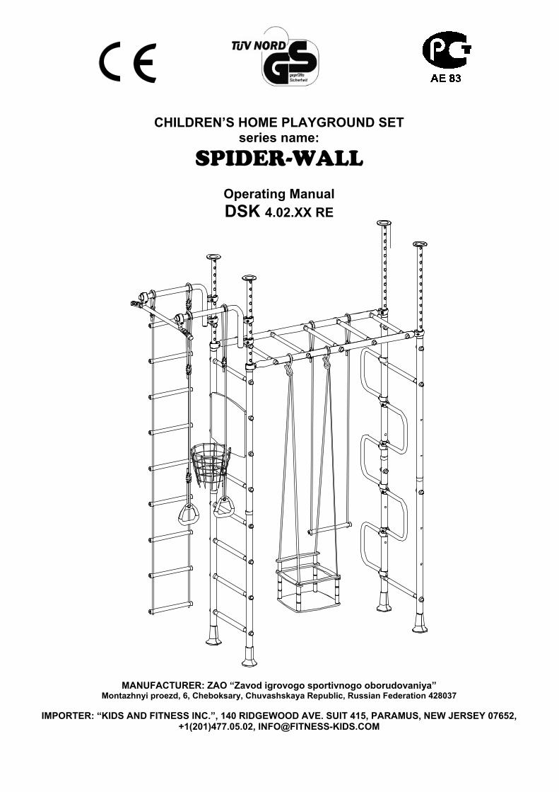
Pic.7 6.3.7. Bring together assembled ladder and assembled stanchions between each other with the help of horizontal
ladder (Pic.8). Screws (item 70, table 2) should not be fastened tight.
А-footsteps made from metal/metal with polyvinyl chlo-ride cover. В- footsteps made from wood
11.03.2010г 11
31
31
33
3346
46
75
85
70
31
31
33
3346
46
75
85
70
Pic.8
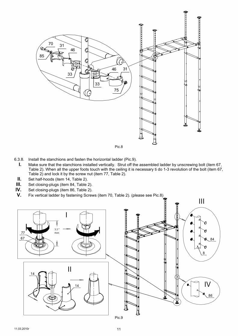
6.3.8. Install the stanchions and fasten the horizontal ladder (Pic.9). I. Make sure that the stanchions installed vertically. Strut off the assembled ladder by unscrewing bolt (item 67,
Table 2). When all the upper foots touch with the ceiling it is necessary ti do 1-3 revolution of the bolt (item 67, Table 2) and lock it by the screw nut (item 77, Table 2).
II. Set half-hoods (item 14, Table 2). III. Set closing-plugs (item 84, Table 2). IV. Set closing-plugs (item 86, Table 2). V. Fix vertical ladder by fastening Screws (item 70, Table 2). (please see Pic.8)
14
14
III
II
86
IV
8
84
14
14
III
II
86
IV
8
8490ma
x
6777
I
90ma
x
6777
I
Pic.9
3.5’’ max

11.03.2010г 12
6.3.9. Install the movable frame, manhole and basketball board in accordance with its’ personal Operating Manuals. 6.4. Instruction of placing the suspended rig. 6.4.1. Suspended rig is delivered to the customer in packaged format. 6.4.2. Assemble the suspended rig in accordance to the assembly instructions written in this suspended rig’s Operat-ing Manuals. General view of the PLAYGROUND SET with recommended placement of suspended rig is shown on the cover of the OM.
6.5. Control of assembling accuracy. 6.5.1. With the help of plumb line check whether the ladder stanchions positioned vertically relative to the floor. If there is deviation you should release bolts (item 67, Table 2) and provide verticality with the help of plumb line. After that you must finally fix stanchions between ceiling and floor with the help of bolts (item 67, Table 2).
MAINTANANCE INSTRUCTION
7.1 Check and control of metal constructions of the PLAYGROUND SET 7.1.1 Before using the PLAYGROUND SET it’s always necessary to check:
• Integrity of the construction, presence of all elements of the PLAYGROUND SET; • Presence of protective plastic plugs and cups on the holders and fasteners where it’s provided by the OM; • Stability of the PLAYGROUND SET and security of the attachment of the ladder.
7.1.2 Periodically, at least once a month, the following should be inspected: • Tightening of fastening and threaded joints; • Absence of displacement of lower (upper) foots from the initial position.
FAILURE TO REGULARY INSPECT AND CHECK PLAYGROUND SET MAY RESULT IN ITS FALL OR TURNOVER!!!
7.2 Check and control of suspended rig. 7.2.1 All fastening elements should be effectively tightened. 7.2.2 Check fastness of joints and elements of suspensions of rig which are done on the base of ropes and cords. 7.2.3 Check integrity of ropes, cords; absence of fraying and damage of fibers of ropes and cords. 7.2.4 Check integrity of wood details of suspended rig.
7.3 Adjustments. 7.3.1 When fastening joints get loose you must tighten them using standard tools. 7.3.2 Install or change closing plugs / plastic cups that cover threaded details when necessary. 7.3.3 All wrecked components must be changed for analogues new ones, produced by the Manufacturer of the
PLAYGROUND SET. 7.3.4 Self-producing of any components of the PLAYGROUND SET is prohibited. Changing wrecked components
of PLAYGROUND SET for self-produced components is prohibited.
OPERATION INSTRUCTION 8.1 Safety precautions. 8.1.1 Total load applied to the PLAYGROUND SET (including on separate suspended rig) during normal use should
not exceed 220 lbs, unless different is stated in the OM of this rig. 8.1.2 To reduce the likelihood of serious injuries it is essential to install shock-absorbing protective surfacing under
and around your PLAYGROUND SET during the time of using it. The size of such shock-absorbing protective surfacing should be not less than (3.3 x 3.3 x 0,3) ft. The use area should be free of other equipment and ob-stacles onto which a child may fall.
8.1.3 Keep a copy of this OM with your important documents during all the time of using the PLAYGROUND SET. 8.2 Operation instructions. 8.2.1 WARNING! Children should use the PLAYGROUND SET under adult supervision. 8.2.2 Only one child at a time should use this PLAYGROUND SET. 8.2.3 Only one type of suspended rig at a time should be used at the PLAYGROUND SET.
Failure to follow safety precautions and operation instructions could result in serious or fatal injury!!
8.3 Recommendations on activity types possible on PLAYGROUND SET. 8.3.1 When regularly playing and exercising on the PLAYGROUND SET general physical conditions of a child
mostly improve (posture, appetite, sleep).

11.03.2010г 13
8.3.2 To develop strength and physical dexterity the following exercises may be done: • on a vertical ladder – climbing up and down the ladder, training of prelum abdominal; • on a horizontal bar – pulling up on hands, press on hands; • on a suspended rope - pulling up on hands, lifting up along the rope; • on a rope ladder – climbing up and down; • on a rings and trapeze –pulling up on hands, front (back) handspring, training of prelum abdominal.
8.3.3 Exact type of exercises and volume of workload must be determined by adults only after consulting with the specialists (doctors, sport trainers, etc.).
TRANSPORATION AND STORING 9.1 PLAYGROUND SET is transported in manufacturer’s packaging via any transport providing it’s safety. 9.2 Before installation to the permanent place the PLAYGROUND SET should be kept in the manufacture’s pack-
age in closed dry place with natural air ventilation.
UTILIZATION 10.1 Before sending the PLAYGROUND SET to utilization it’s necessary to:
• Dissemble the PLAYGROUND SET in the order inverted to the assembly order; • Sort details on the type of materials they manufactured of.
10.2 There are no dangerous or hazardous for health and life substances in the components of PLAYGROUND SET.
10.3 Utilization should be conducted in accordance with appropriate rule and regulations of your region/state.
WARRANTY
11.1 Manufacturer guarantees that the PLAYGROUND SET is in compliance with the technical conditions require-ments of TU 9610-002-49248007-2001 (Russian Federation standard), GOST 25779 (Russian Federation standard), DIN EN 71-1:2006, DIN EN 71-3:2002, DIN EN 71-8:2006 when rules of transportation, storing, in-stallation and operation are observed.
11.2 Warranty period of the PLAYGROUND SET is 12 (twelve) months since the date of purchase. 11.3 The warranty does not cover the PLAYGROUND SET if:
• It was damaged during transportation by the customer; • rules of transportation, storing, installation and operation, stated in this OM, were not observed.
CERTIFICATE OF WORK ACCEPTANCE Children’s home playground set series “SPIDER-WALL” design DSK 4.02. _____________________________
Comply with technical conditions requirements TU 9610-002-49248007-2001(Russian Federation standard), GOST 25779 (Russian Federation standard), DIN EN 71-1:2006, DIN EN 71-3:2002, DIN EN 71-8:2006 and recognized as serviceable. Manufacturing date «___»______________ 2010. _____________ _____________ Controller from Quality control Stamp Quality control

11.03.2010г 14
Appendix 1. SECTION 4 OF THE CONSUMER PRODUCT SAFETY COMMISSION’S OUTDOOR HOME PLAYGROUND SAFETY HANDBOOK Select Protective Surfacing 1 1. One of the most important things you can do to reduce the likelihood of serious head injuries is to install shock-absorbing protec-tive surfacing under and around your play equipment. The protective surfacing should be applied to a depth that is suitable for the equipment height in accordance with ASTM Specification F 1292. There are different types of surfacing to choose from; whichever product you select, follow these guidelines: 1.1 Loose-Fill Materials: 1.1.1 Maintain a minimum depth of 9 inches of loosefill materials such as wood mulch/chips, engineered wood fiber (EWF), or shredded/recycled rubber mulch for equipment up to 8 feet high; and 9 inches of sand or pea gravel for equipment up to 5 feet high. NOTE: An initial fill level of 12 inches will compress to about a 9- inch depth of surfacing over time. The surfacing will also compact, displace, and settle, and should be periodically refilled to maintain at least a 9- inch depth. 1.2 Use a minimum of 6 inches of protective surfacing for play equipment less than 4 feet in height. If maintained properly, this should be adequate. (At depths less than 6 inches, the protective material is too easily displaced or compacted.) NOTE: Do not install home playground equipment over concrete, asphalt, or any other hard surface. A fall onto a hard surface can result in serious injury to the equipment user. Grass and dirt are not considered protective surfacing because wear and environ-mental factors can reduce their shock absorbing effectiveness. Carpeting and thin mats are generally not adequate protective sur-facing. Ground level equipment – such as a sandbox, activity wall, playhouse or other equipment that has no elevated play surface – does not need any protective surfacing. 1.3 Use containment, such as digging out around the perimeter and/or lining the perimeter with landscape edging. Don’t forget to account for water drainage. 1.3.1 Check and maintain the depth of the loose-fill surfacing material. To maintain the right amount of loose- fill materials, mark the correct level on play equipment support posts. That way you can easily see when to replenish and/or redistribute the surfacing. 1.3.2 Do not install loose fill surfacing over hard surfaces such as concrete or asphalt. 1.4 Poured-In-Place Surfaces or Pre-Manufactured Rubber Tiles—You may be interested in using surfacing other than loose-fill materials – like rubber tiles or poured-in-place surfaces. 1.4.1 Installations of these surfaces generally require a professional and are not “do-it-yourself” projects. 1.4.2 Review surface specifications before purchasing this type of surfacing. Ask the installer/manufacturer for a report showing that the product has been tested to the following safety standard: ASTM F 1292 Standard Specification for Impact Attenuation of Surfacing Materials within the Use Zone of Playground Equipment. This report should show the specific height for which the sur-face is intended to protect against serious head injury. This height should be equal to or greater than the fall height – vertical dis-tance between a designated play surface (elevated surface for standing, sitting, or climbing) and the protective surfacing below – of your play equipment. 1.4.3 Check the protective surfacing frequently for wear. 1.5 Placement—Proper placement and maintenance of protective surfacing is essential. Be sure to: 1.5.1 Extend surfacing at least 6 feet from the equipment in all directions. 1.5.2 For to-fro swings, extend protective surfacing in front of and behind the swing to a distance equal to twice the height of the top bar from which the swing is suspended. 1.5.3 For tire swings, extend surfacing in a circle whose radius is equal to the height of the suspending chain or rope, plus 6 feet in all directions.
Use Zone for Single- and Multi-Axis Swings
1 More information re surfacing you can find in “Surfacing Materials for Indoor Play Areas- Impact Attenuation Test Report” issued by Consumer Products Safe-ty Commission in December 2005.