dscan user manual version 1 - us dental depot · 4 © 2012 enter your company name 1 overview dscan...
TRANSCRIPT

Copyright (c) 2004 - 2012
DScan User ManualVersion 1.1

2
© 2012 Enter your company name
Table of Contents
Part I Overview 4
Part II New Installation 6
................................................................................................................................... 81 System Requirements
................................................................................................................................... 92 Hardware Unpackaging
................................................................................................................................... 183 Hardware Connections
................................................................................................................................... 274 Turn on/off sequence
................................................................................................................................... 305 Configure System
................................................................................................................................... 396 Reset Axes
................................................................................................................................... 407 Basic Mode Scan
Part III DScan User's Guide 43
................................................................................................................................... 441 Basic Mode
......................................................................................................................................................... 45UI Elements
.................................................................................................................................................. 45Workflow Control Buttons
.................................................................................................................................................. 46Toolbar Commands
........................................................................................................................................... 46Import Files
........................................................................................................................................... 46Export Files
........................................................................................................................................... 46Undo/Redo
........................................................................................................................................... 47Mesh Selectors
........................................................................................................................................... 47Fill holes
........................................................................................................................................... 47Spike Removal
........................................................................................................................................... 48Delete Selected triangles
........................................................................................................................................... 48Standard View s
........................................................................................................................................... 48Show /Hide Mesh Borders
................................................................................................................................... 492 Job Driven Mode
......................................................................................................................................................... 50Acquisition Workflow
.................................................................................................................................................. 52Workarea Definition
.................................................................................................................................................. 54Total Model Acquisition
.................................................................................................................................................. 56Neighbors
.................................................................................................................................................. 58Inplace
.................................................................................................................................................. 60Multidie
.................................................................................................................................................. 62Registration
.................................................................................................................................................. 64Finish
.................................................................................................................................................. 65Gum
.................................................................................................................................................. 67Waxup
.................................................................................................................................................. 71Antagonist
......................................................................................................................................................... 76UI Elements
.................................................................................................................................................. 77Arc Jaw
.................................................................................................................................................. 78Workflow Control Buttons
.................................................................................................................................................. 80Model Tree
.................................................................................................................................................. 80Step Bar
.................................................................................................................................................. 80Toolbar Commands
........................................................................................................................................... 81Import Files

3Contents
© 2012 Enter your company name
........................................................................................................................................... 81Export Files
........................................................................................................................................... 81Undo/Redo
........................................................................................................................................... 81Mesh Selectors
........................................................................................................................................... 82Fill holes
........................................................................................................................................... 82Spike Removal
........................................................................................................................................... 82Delete Selected triangles
........................................................................................................................................... 82Standard View s
........................................................................................................................................... 82Show /Hide Mesh Borders
........................................................................................................................................... 83Show colormap
........................................................................................................................................... 83Gum registration slider
................................................................................................................................... 843 Preferences

4
© 2012 Enter your company name
1 Overview
DScan is an high-accuracy and high-performance structured light scanner that isextremely user-friendly and can export data into the most common formats used byCAD/CAM applications
Dscan has been developed specifically for the dental industry as an open andcompletely customizable system, and it is offered to OEM companies that want tobrand the instrument and integrate it into their product lines. EGSolutions offers acomplete customization of the scanner (both the software and hardware) by fulfillingOEM-specific technical and design requests
The high accuracy and the robust technical features of Dscan, the unique design ofthe optics for example, enables technicians to acquire complete arc jaw, stumpsand impressions. The scan process is completely automated and uses twosynchronized axes controlled by an industrial programmable logic controller (PLC).Users can customize the acquisition strategies and parameters
Dscan key features include:
High Accuracy and reproducibility: accuracy as high as 15 microns, tested in ametrology environment
Customizable acquisition strategies: arc jaw, stumps, bridges, antagonists, gumand wax up
Impression acquisition
Maximum reliability: high quality mechanical and electronic components
Open system: dataset are exported in common formats, including STL, PLY andASC which can be read by any CAD|CAM system
Compact size: Dscan's reduced size and weight means it can fit in anylaboratoty
Lifetime license: maintenance and update fees available upon request

5Overview
© 2012 Enter your company name
DScan Technical Specifications:
3D Scanning principle Structured light
Camera resolution 1.3 megapixel
Light source LED, 150 ANSI-lumen 30.000 hours
Rotary stage 2 axis movement Rotation, Tilting
3D scanning area (W x H x D) 90 x 80 x 55 mm
Accuracy 0.015 mm
Point distance 0.04 mm
Intput data format STL, ASC, PLY, OBJ
Output data format STL
Interface USB 2.0, Ethernet
Size (W x H x D) 250 x 450 x 450 mm
Weight 13.5 kg

6
© 2012 Enter your company name
2 New Installation
To connect a Scanner and a PC for the first time and to install all the requiredsoftware the steps are:
1. Unpackaging and Connect the Hardware
2. Install and Configure the software (Not required if a PC is shipped together withthe scanner)
3. Test the Installation
7New Installation
© 2012 Enter your company name
Unpackage and Connect the Hardware
1. Verify if the PC hardware is complaint with the recommended requirements. (Not required if a PC is shipped together with the scanner)
2. Unpackaging the Scanner
3. Connect the Scanner to the PC
4. Turn on/off sequence
Install and Configure the Software
Warning: If a PC is shipped together with the scanner this step is not required
Before installing and configure the software Scanner and PC have to be properlyconnected and turned on in the right sequence.
1. Configure System
* An Internet connection has be active in order to correctly register the software with akeycode license
Test the installation
Before running for the first time the Scanner application and test it the two previoussteps has to be performed:
1. Perform a Reset Axis
2. Acquire a model in Basic Mode

8
© 2012 Enter your company name
2.1 System Requirements
The following configuration is RECOMMENDED for best results:
Processor: Intel Core i7 or higher
Memory: 8 GB or higher
Video card: Nvidia 5xx series or higher / ATI 5xxx series or higher, with 1Gb ormore video ram
Operating system: Windows 7 64bit*
Network interface card: 2 x RJ45 Ethernet adapters or 1 x RJ45 Ethernetadapter + 1 x Wireless adapter
* 64bit OS is a mandatory requirement for DentalSuite

9New Installation
© 2012 Enter your company name
2.2 Hardware Unpackaging
Unpackaging
The DScan is shipped inside a wooden box. You need a slotted screwdriver toopen it
Bend the eight stops using the slotted screwdriver to release the top cover plate

10
© 2012 Enter your company name

11New Installation
© 2012 Enter your company name
Remove the top cover

12
© 2012 Enter your company name
13New Installation
© 2012 Enter your company name
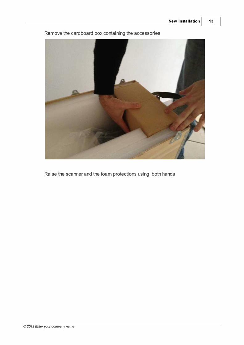
Remove the cardboard box containing the accessories
Raise the scanner and the foam protections using both hands

14
© 2012 Enter your company name
Put it on the floor

15New Installation
© 2012 Enter your company name
Remove the two lateral foam protections

16
© 2012 Enter your company name
Remove the protection bag and move the Scanner on a table close to the PC
Open the frontal cover and check the position of the rotating table. If the position isnot horizontal gently move it manually until it is more or less aligned with the innercover. Reset Axis operation will be performed later in order to achieve the perfectrotary plate position
Warning: Do not perform this operation if the scanner is turned on!
Content of the box
The scanner is packed with all the accessories required to connect and operate.They are stored inside the cardboard box
A) DVD containing:
1. Calibration folder
2. Software folder
3. Documetation folder

17New Installation
© 2012 Enter your company name
B) Blu Tack adhesive
C) Scanner Power cord
D) Flat Circular plate
E) Multidie plate
F) Calibration Glass
G) RJ45 cable
H) USB cable
I) Projector remote control
L) VGA video cable

18
© 2012 Enter your company name
2.3 Hardware Connections
Hardware Overview
The DScan is provided by two Power Switch and some Sockets
The Projector Switch button is on the frontal panel
In the back panel there are:
1. Power Switch: general power button
2. AC Socket
3. VGA connector: PC -> scanner projector
4. USB connector: PC -> scanner cameras connection

19New Installation
© 2012 Enter your company name
5. RJ45 connector: PC -> scanner electrical motors connection

20
© 2012 Enter your company name
PC Scanner connections
1. Connect the mouse and the keyboard using two USB port in the PC back panel.
The PC can be provided by a wireless connection for the mouse and keyboard, in
this case only one USB port is used
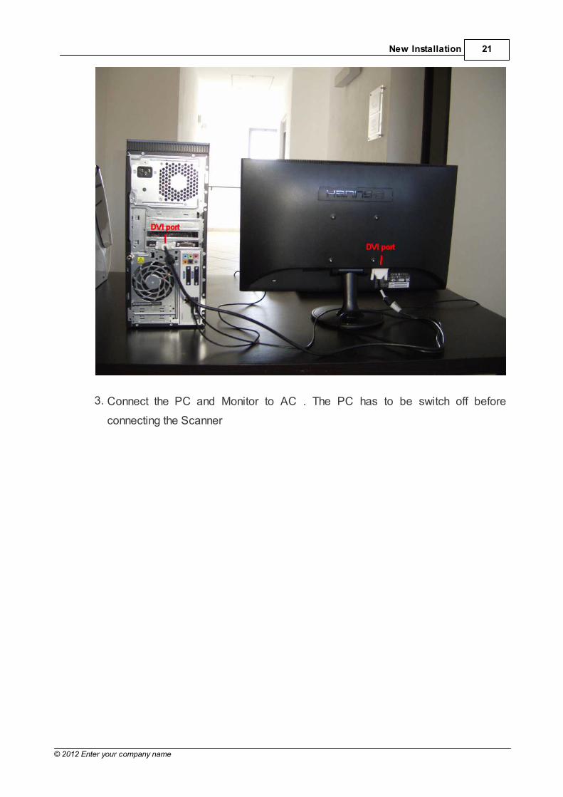
2. Connect the the first PC DVI port to the monitor DVI. Depending from the
graphical device and monitor also VGA cable can be used. Sometime can be
used adapters DVI -VGA in order to connect the PC and the scanner projector
21New Installation
© 2012 Enter your company name
3. Connect the PC and Monitor to AC . The PC has to be switch off before
connecting the Scanner

22
© 2012 Enter your company name
4. Connect a free PC USB 2.0 port to the scanner USB

23New Installation
© 2012 Enter your company name
5. Plug the PC RJ45 port to the Scanner RJ45. The PC and the scanner have to bedirectly connected.

24
© 2012 Enter your company name
6. Place the VGA cables on the back of the Scanner and in the second DVI PC port
(an adapter DVI -VGA not included is required depending from the PC graphical
device installed )

25New Installation
© 2012 Enter your company name
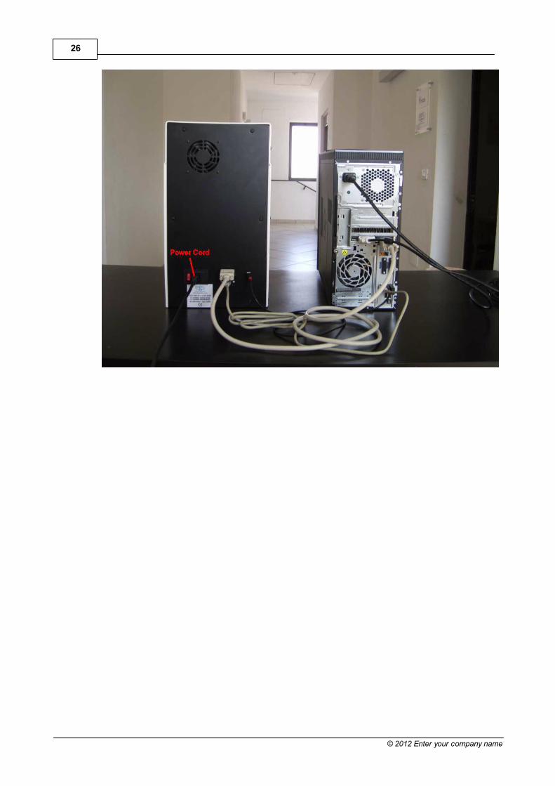
7. Plug the Power Cord on the back of the Scanner device
26
© 2012 Enter your company name
27New Installation
© 2012 Enter your company name
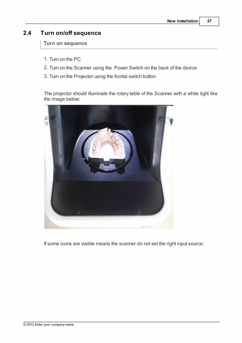
2.4 Turn on/off sequence
Turn on sequence
1. Turn on the PC
2. Turn on the Scanner using the Power Switch on the back of the device
3. Turn on the Projector using the frontal switch button
The projector should illuminate the rotary table of the Scanner with a white light likethe image below:
If some icons are visible means the scanner do not set the right input source:

28
© 2012 Enter your company name
To solve the issue use the Source Button in the remote control.

29New Installation
© 2012 Enter your company name
Turn off sequence
1. Turn off the Projector using the frontal button
2. Turn off the scanner using the Power Switch
3. Turn off the PC

30
© 2012 Enter your company name
2.5 Configure System
Configure System Check List
1. Turn on the PC, Turn on the Scanner and then turn on Scanner Projector usingfrontal button
2. Using remote control to force the projector to find the PC input
3. UAC disable, the current user has to be Admin type
4. Double monitor Second Monitor one has to have 1280x720. (No ScreenSaver)
5. IP address for the ethernet scanner device 192.168.179.54
6. Power Option High Performance
Turn off display Never
Put the computer to sleep Never
Advance power option USB setting disable
7. Install flexscan 3.0 using default parameters and folders
8. Create two Folders in the PC:
C:\Program Files\3D3Solutions\FlexScan3D 3\Projects
C:\Program Files\3D3Solutions\FlexScan3D 3\Calibrations
9. From Scanner CD copy the Calibration02 folder inside Flexscan Calibrationsfolder created in the previous step
10.Run Flexscan3.0 (PWD is required) and change Settings:
Default Project Path: C:\Program Files\3D3Solutions\FlexScan3D 3\Projects
Default Calibration Path: C:\Program Files\3D3Solutions\FlexScan3D 3\Calibrations
11.Load Calibration02
12.Create Project03
Threshold [90%]
Clean up Aggressive
Mode Standard
(Delete always testing scans before close Flexscan 3.0)
13.Install DentalCAD, select the Flexscan3.0 folder when required by setup (PWD

31New Installation
© 2012 Enter your company name
is required)
14.Copy from CD Scanner Calibration.xml file inside C:\Users\YourUser\AppData\Roaming\EGS\DentalCAD\ScanManOutput folder
15.Run Scanner Software and perform a Reset Axis
16.Run Basic Mode with a model

32
© 2012 Enter your company name
User Acces Control (UAC)
Projector Resolution
Second Monitor one has to have 1280x720 resolution

33New Installation
© 2012 Enter your company name
Scanner Network IP
The Ethernet adapter used to connect the PC and the Scanner has to beconfigured as below:

34
© 2012 Enter your company name
Screen Saver Status

35New Installation
© 2012 Enter your company name
Power Saving setting
The profile has to be set as: High Performance
Flexscan 3D 3 Settings
Flexscan 3D 3 Load Calibrations

36
© 2012 Enter your company name
Load the Calibration02
Flexscan 3D 3 Project03
Create a New Project03

37New Installation
© 2012 Enter your company name
Threshold [90%]
Clean up Aggressive
Mode Standard

38
© 2012 Enter your company name

39New Installation
© 2012 Enter your company name
2.6 Reset Axes
Reset axis command have to be used every time the scanner stops and the rotarytable is not properly oriented.
Warning: Do not insert any model in the Scanner to perform an Reset Axes!
1. Double click on Dscan icon
2. Select Basic Scanner Mode
3. Click Cancel in the Basic Mode Scan dialog box
4. In the Drop down menu click on Tool -> Reset Axes
In a few second the movable plate start to rotate and tilt. After some rotations itstops automatically properly aligned

40
© 2012 Enter your company name
2.7 Basic Mode Scan
The Basic Mode is a general purpose acquisition cycle used to test the scanner orto acquire a very simple model. For a more detailed description see Basic Mode
1. Fix a model on the flat circular plate using Blu Tack adhesive. The incisors teethhave to be oriented as below
2. Insert the flat circular plate in the scanner, Incisors to the back of the scanner

41New Installation
© 2012 Enter your company name
3. Click Green arrow button in top left corner. The Scan Dialog boxappears

42
© 2012 Enter your company name
4. Click on Scan button. The scan starts. After the first 3 acquired images pointsshould be visible on the graphic area
5. When Finalize button becomes active click it to transform points in amesh
The Scan can be interrupted using the red square button: . If you stop theScanner the movable plate will be moved to zero position automatically

43New Installation
© 2012 Enter your company name
3 DScan User's Guide
Dscan can run in two main ways:
1. Basic Mode
2. Job Driven Mode
1. Loading manually a Job Definition file
2. Invoked automatically from a CAD application

44
© 2012 Enter your company name
3.1 Basic Mode
Basic Mode is simple way to run the scanner in order to scan a model withoutdefining a specific strategy. It is possible to acquire model not related to dentalapplication.
By default a 16 positions cycles is used but this can be changed depending fromthe complexity of the object to acquire.
45DScan User's Guide
© 2012 Enter your company name
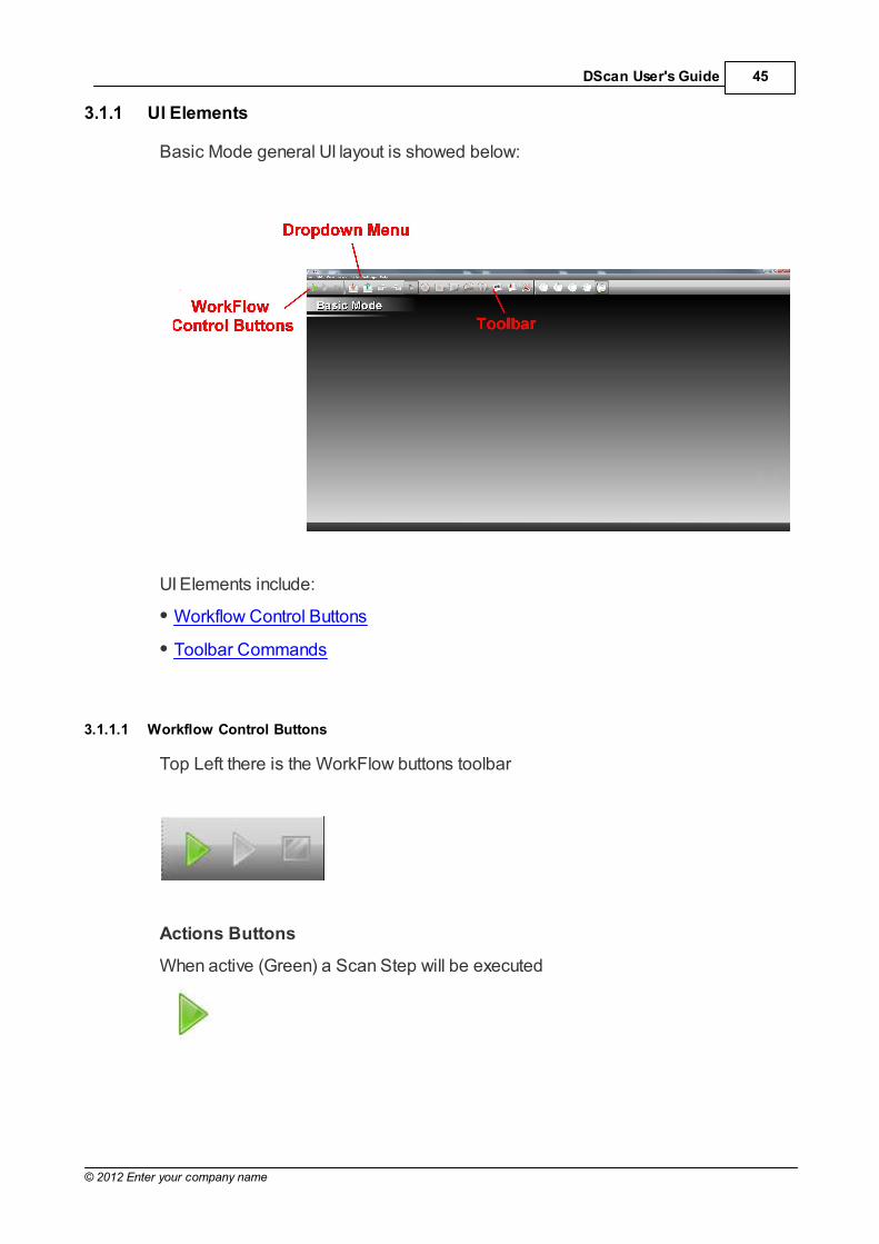
3.1.1 UI Elements
Basic Mode general UI layout is showed below:
UI Elements include:
Workflow Control Buttons
Toolbar Commands
3.1.1.1 Workflow Control Buttons
Top Left there is the WorkFlow buttons toolbar
Actions Buttons
When active (Green) a Scan Step will be executed

46
© 2012 Enter your company name
When active (Red) a Scan Step is running. Using this button it is possible to stopthe Scanner. It immediately stops to acquire data and returns in zero axis position
When active (Yellow) a Finalize computation is performed. Points acquired by thescanner become meshes
3.1.1.2 Toolbar Commands
In the following, for each command of the toolbar, from left to right, a briefdescription is provided.
3.1.1.2.1 Import Files
An Open file dialog pop up allowing the user to load multiple STL files inthe scanner
3.1.1.2.2 Export Files
An Export Files dialog pop up allowing the user to export multiple STLfiles from the scanner
3.1.1.2.3 Undo/Redo
Undoes or Redoes last operation

47DScan User's Guide
© 2012 Enter your company name
3.1.1.2.4 Mesh Selectors
Disabled selection: Switch to this tool when you want to simply navigateon model without any active selector
Point selection: allows to select all the triangles inside a small circularregion
Rectangle selection: allows to select all triangles inside a rectangularregion
Polygon selection: allows to select all triangles inside a polygonal region
Lazo selection: allows to select all triangles inside a free-hand closedregion
Cluster selection: selects all triangles in the picked cluster
3.1.1.2.5 Fill holes
Fills the holes in the mesh
3.1.1.2.6 Spike Removal
Flatten the triangles in a small area defined by polygon selection

48
© 2012 Enter your company name
3.1.1.2.7 Delete Selected triangles
Removes all the selected triangles
3.1.1.2.8 Standard View s
Sets the viewport to a standard direction
3.1.1.2.9 Show /Hide Mesh Borders
Graphical display option for showing or not the borders of the mesh inhighlight

49DScan User's Guide
© 2012 Enter your company name
3.2 Job Driven Mode
Upon starting the Scanner prompts the user to choose the acquisition Options andthe scanning Strategy to use
Three Strategies are available:
Inplace: Standard strategy. The job stumps stay in the original position duringscanning. No realign is required
Multidie: Alternate strategy. The job stumps are positioned on a specialdevice. They need to be realigned manually later
Fast Coping: it is particularly useful when a single Stump has to be scanned
The below Options allows the user to add elements to scan:
Gum
Waxup
Antagonist
Workarea definition flag force the scanner to focus on a specific arc jaw areaavoiding to acquire the entire model saving computational time

50
© 2012 Enter your company name
3.2.1 Acquisition Workflow
Depending from the strategy and option selected, the Dscan sets several Steps inorder to acquire the arc jaw model and related stump in the best possible way. Thissets of Steps are called Acquisition Workflow. To help the user to navigate in theworkflow a wizard like UI is provided. There are three type of Steps used byscanner to make an Acquisition Workflow:
1. Scan Step: The model is scanned using several positions depending from thespecific Step. After a Finalize meshes are created. Obviously an arc jaw, a toothor other models have to be inserted in the scanner by the user
2. Registration Step: Meshes are aligned each other. The alignment requires toselect three points on a fixed mesh and the homologous ones on a movablemesh. The application compute the transformation in order to minimize thedistances. In order to align to mesh they have to have overlapping areas. It is notpossible to align meshes without overlapping
3. Assignement Step: Meshes are segmented and assigned to the appropriateteeth
For example below are listed the Steps to acquire a simple job using Inplacestrategy and Workarea flag on. No additional options selected
1. Workarea Definition
2. Total Model Acquisition
3. Neighbors
4. Inplace
5. Registration
6. Finish
The same Workflow adding Gum Option:
1. Workarea Definition
2. Total Gum Acquisition
3. Total Model Acquisition
4. Gum Registration
5. Gum
6. Neighbors

51DScan User's Guide
© 2012 Enter your company name
7. Inplace
8. Registration
9. Finish
In the following sections Steps are described in details

52
© 2012 Enter your company name
3.2.1.1 Workarea Definition
The Workarea Definition is a Scan Step. Ii has the goal to focus all the scanningand computation effort to a specific arc jaw area avoiding to acquire the entiremodel saving time
Workarea Definition
1. Quick acquisition, only 2 positions by default, of the total model is done. NoFinalize is required
2. Teeth segmentation and linking. When all the teeth are linked to a workarea, thestep is completed. In this step the top view is blocked, and only panning is

53DScan User's Guide
© 2012 Enter your company name
allowed.
54
© 2012 Enter your company name
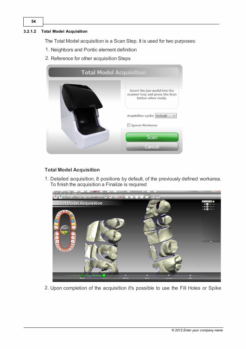
3.2.1.2 Total Model Acquisition
The Total Model acquisition is a Scan Step. It is used for two purposes:
1. Neighbors and Pontic element definition
2. Reference for other acquisition Steps
Total Model Acquisition
1. Detailed acquisition, 8 positions by default, of the previously defined workarea.To finish the acquisition a Finalize is required
2. Upon completion of the acquisition it's possible to use the Fill Holes or Spike

55DScan User's Guide
© 2012 Enter your company name
removal tool to heal the mesh. When no further editing is needed, the step iscompleted

56
© 2012 Enter your company name
3.2.1.3 Neighbors
Neighbors is an Assignment Step. A manual segmentation is needed to identify allthe neighbors and pontic elements in the Total Model acquisition.
This step is usually performed using the polygon and the lasso selection tools.
Neighbors segmentation
1. Correct manual segmentation of the single meshes:
2. Linking of the segmented meshes to the preparation elements; pick thesegment and the arcjaw teeth by single click to link;

57DScan User's Guide
© 2012 Enter your company name
3. Correctly linked elements are shown in pale orange; unlinked elements areshown in bright orange. Once all elements have been correctly linked the step iscomplete.

58
© 2012 Enter your company name
3.2.1.4 Inplace
Inplace
The Inplace is a Scan Step. This strategy implies keeping the stumps on the base,while removing all the other elements. Stumps scanned this way are already in theright position, no additional step are required
If the preparation involves several stumps the scanner automatically could split theacquisition in two or more separate Steps
Inplace workflow
1. Acquire the stumps, 16 positions by default. A Finalize is required. Elementsscanned this way are already registered with the total acquisition:

59DScan User's Guide
© 2012 Enter your company name
2. Link the elements; pick the segment and the arcjaw teeth by single click to link
If one tooth is not well acquired don't assign it. Remove from the base the rightones and repeat the scan running it from pulldown menu. (The Scan button isinactive)
Dscan deletes automatically the not assigned mesh and repeat the acquisitioncycle

60
© 2012 Enter your company name
3.2.1.5 Multidie
Multidie
Multidie is a Scan Step. This strategy implies removing the stumps from the baseand inserting them into a special tablet, according to a specific pattern. Thestumps are scanned in a different position respect the arc jaw, an additionalregistration step is required and mandatory to move them in the right position. Asreference the Total Model is used
.
If the preparation involves more than five stumps the scanner automatically split theacquisition in two or more separate Steps
Multidie workflow
1. Acquire the multidie support, 16 positions by default. A Finalize is required tofinish. The meshes are assigned automatically by DScan if the flagAutoassignment is on

61DScan User's Guide
© 2012 Enter your company name
If one tooth is not well acquired deassign it clicking on the related arc jaw icon.Remove from the rotating tablet of the scanner the right ones, move just a little thewrong stump and repeat the scan running it from pulldown menu. (The Scan buttonis inactive). When the multidie scan dialog box appears unflag the Autoassignment. Dscan deletes automatically the not assigned mesh and repeat the acquisitioncycle

62
© 2012 Enter your company name
3.2.1.6 Registration
Registration has the goal to align meshes to other one. Usually stumps or waxup are aligned using Total Model. Registration Step is mandatory for stumps acquiredusing the Multidie approach, and optional for Inplace acquisition.
Registration
1. Click in the arc jaw on the tooth to register: A dialog box appears
2. Select three or more homologous points on both the single teeth and the totalmodel. At any time is possible to RESET the selection or ABORT the operation.Once done click the REGISTER button

63DScan User's Guide
© 2012 Enter your company name
3. By clicking the OK button the operation is completed. A successfully registeredelement is shown with a green label in the jaw view:
4. Repeat the step for each element to align

64
© 2012 Enter your company name
3.2.1.7 Finish
When all the Steps in the Acquisition Workflow are done, the scanning process iscomplete. The Scanner application is ready to move all the data acquired to theModeling Prosthesis phase. This is automatically done clicking on the NEXT button

65DScan User's Guide
© 2012 Enter your company name
3.2.1.8 Gum
When Gum option is checked the Scanner add three Steps to the AcquisitionWorkflow:
1. Total Gum Model Acquisition
2. Gum Registration
3. Gum Assignment
Total Gum Model Acquisition
Total Model with gum is acquired, 8 positions by default. A Finalize is required
Gum Registration
This Step is composed by two parts:
1. A not mandatory Registration of the two total model acquisitions
2. An semiautomatic segmentation. A specific tool for gum identification,
accessible via the button , is available. Using this tool and proper scannedtotal models, it's possible to isolate gum without the need of manualsegmentation
66
© 2012 Enter your company name
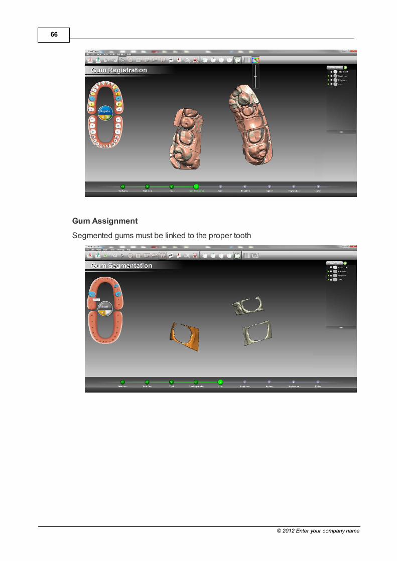
Gum Assignment
Segmented gums must be linked to the proper tooth

67DScan User's Guide
© 2012 Enter your company name
3.2.1.9 Waxup
When Waxup option is checked the Scanner add four Steps to the AcquisitionWorkflow:
1. Total Waxup Model Acquisition
2. Total Waxup Model Registration
3. Waxup Acquisition
4. Waxup Registration
The purpose of these Steps is to acquire shape to be used instead of the defaultones available from internal DentalCAD libraries. It means that some modeling jobhas to be performed to make the shape acquired compatible. This job is done inthe Waxup Acquisition Step mainly using Delete and Fill hole commands
Total Waxup Model Acquisition
Total Model with Waxup is acquired, 8 positions by default. A Finalize is required
Total Waxup Model Registration
A not mandatory Registration of the two total model acquisitions is available ifrequired
Waxup Acquisition
This Step is composed by two parts
68
© 2012 Enter your company name
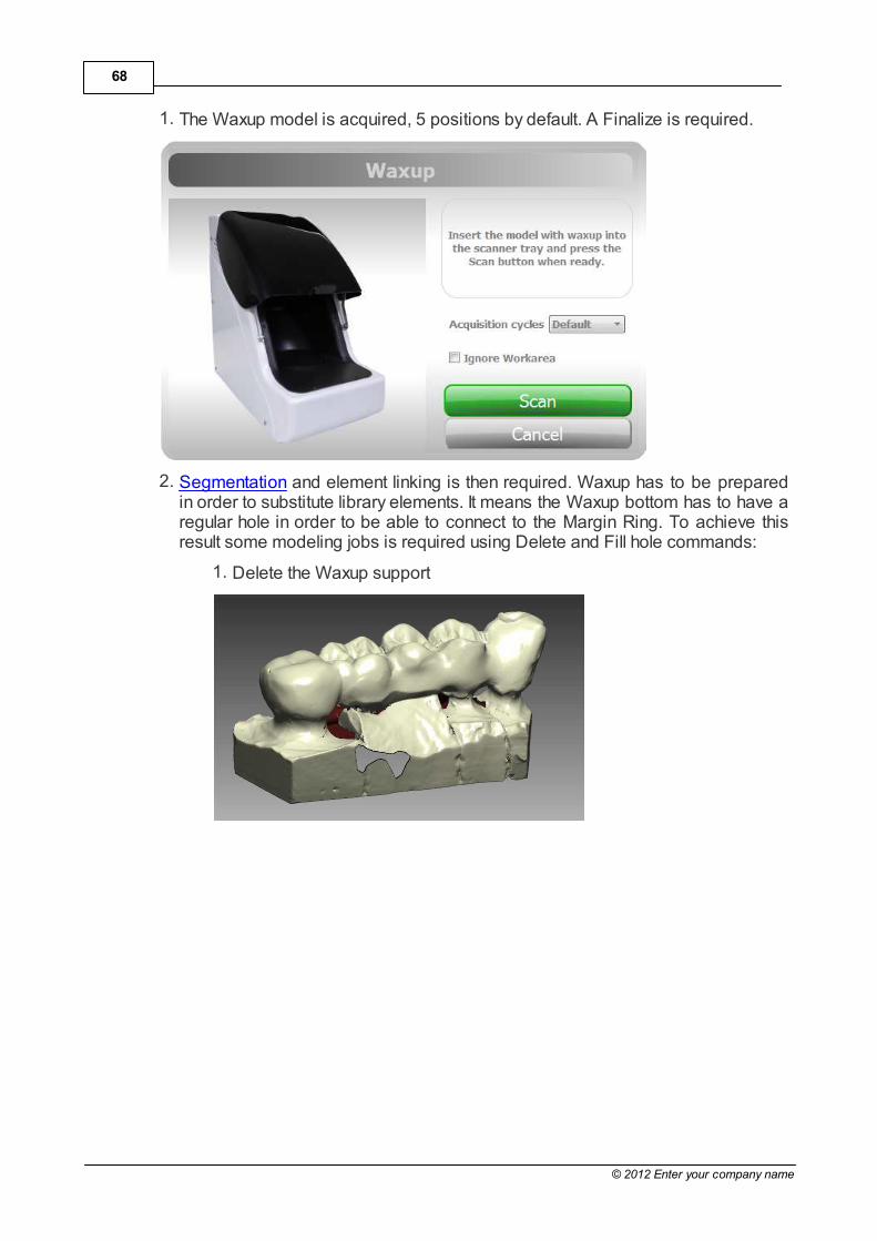
1. The Waxup model is acquired, 5 positions by default. A Finalize is required.
2. Segmentation and element linking is then required. Waxup has to be preparedin order to substitute library elements. It means the Waxup bottom has to have aregular hole in order to be able to connect to the Margin Ring. To achieve thisresult some modeling jobs is required using Delete and Fill hole commands:
1. Delete the Waxup support

69DScan User's Guide
© 2012 Enter your company name
2. Split the total shape in single shapes cutting connectors if present
3. Recreate lateral faces using fill hole command
4. Delete the bottom of the waxup in order to create the base hole

70
© 2012 Enter your company name
Waxup Registration
A not mandatory Registration of Waxup shapes is available if required. Thereference model will be the Total Waxup Model

71DScan User's Guide
© 2012 Enter your company name
3.2.1.10 Antagonist
Antagonist
When Antagonists Option only is checked (no checkbite), the Scanner add threeSteps to the Acquisition Workflow:
1. Couple Model Acquisition
2. Antagonists Acquisition
3. Antagonists Registration
Couple Model Acquisition
Acquire the Couple Model. A quick acquisition, 6 positions by default, of both arcjaws, superior and inferior, is performed.

72
© 2012 Enter your company name
Antagonist Acquisition
This Step is composed by two parts:
1. The user is required to scan the full antagonists arc jaw, 8 positions by default.A Finalize is required
2. Segmentation and element linking is then required

73DScan User's Guide
© 2012 Enter your company name
Antagonist Registration
Perform the registration between the antagonist jaw and the Model Couple bypicking the contact points. Once all elements have been correctly registered thestep is complete.
Checkbite

74
© 2012 Enter your company name
When Antagonist with Checkbite option is checked, the Scanner add one Steps tothe Acquisition Workflow:
1. Checkbite acquisition
Checkbite acquisition
This Step is composed by two parts:
1. Total Model Acquisition with checkbite, 5 positions by default. A Finalize isrequired
2. At this point segmentation of the checkbite is needed to link each element to theproper tooth. After proper segmentation and linking the workflow proceeds in thestandard way

75DScan User's Guide
© 2012 Enter your company name

76
© 2012 Enter your company name
3.2.2 UI Elements
Scanner general UI layout is showed below:
UI Elements include:
Arc Jaw
Workflow Control Buttons
Model Tree
Step Bar
Toolbar Commands

77DScan User's Guide
© 2012 Enter your company name
3.2.2.1 Arc Jaw
The left panel indicates which tooth are needed by the Dental Scanner; the user isexpected to load the elements.

78
© 2012 Enter your company name
3.2.2.2 Workflow Control Buttons
In the middle of the arc jaw on the left three buttons drive the Acquisition Workflow.More than one button can be active in the same time
Next/Previous Buttons
When active (Green) it is possible to move to the next Step of Acquisition Workflow
When active (Yellow) it is possible to move to the previous Step of AcquisitionWorkflow

79DScan User's Guide
© 2012 Enter your company name
Actions Buttons
When active (Green) a Scan Step will be executed
When active (Red) a Scan Step is running. Using this button is possible to stop theScanner. It immediately stops to acquire data and returns in zero axis position
When active (Yellow) a Finalize computation is performed. Data acquired by thescanner become meshes
When active (Blue) a Registration Step is performed

80
© 2012 Enter your company name
3.2.2.3 Model Tree
The right panel is the Model Tree that shows all the teeth loaded for each jobdefined.
Flag/Unflag the tooth drives its visibility. Mouse wheels drives the transparency
3.2.2.4 Step Bar
In the bottom of the screen the Step Bar shows all Acquisition Workflow Steps andhighlight the current on
It is possible to jump from one Step to another one simply clicking on the greenbutton.
3.2.2.5 Toolbar Commands
In the following, for each command of the toolbar image, from left to right, a briefdescription is provided.

81DScan User's Guide
© 2012 Enter your company name
3.2.2.5.1 Import Files
An Open file dialog pop up allowing the user to load multiple STL files inthe scanner
3.2.2.5.2 Export Files
An Export Files dialog pop up allowing the user to export multiple STLfiles from the scanner
3.2.2.5.3 Undo/Redo
Undoes or Redoes last operation
3.2.2.5.4 Mesh Selectors
Disabled selection: Switch to this tool when you want to simply navigateon model without any active selector
Point selection: allows to select all the triangles inside a small circularregion
Rectangle selection: allows to select all triangles inside a rectangularregion
Polygon selection: allows to select all triangles inside a polygonal region

82
© 2012 Enter your company name
Lazo selection: allows to select all triangles inside a free-hand closedregion
Cluster selection: selects all triangles in the picked cluster
3.2.2.5.5 Fill holes
Fills the holes in the mesh
3.2.2.5.6 Spike Removal
Flatten the triangles in a small area defined by polygon selection
3.2.2.5.7 Delete Selected triangles
Removes all the selected triangles
3.2.2.5.8 Standard View s
Sets the viewport to a standard direction
3.2.2.5.9 Show /Hide Mesh Borders
Graphical display option for showing or not the borders of the mesh inhighlight

83DScan User's Guide
© 2012 Enter your company name
3.2.2.5.10 Show colormap
Enable/Disable the colormap while registering the elements
3.2.2.5.11 Gum registration slider
The slider is active only when acquiring the gum, refer to Gum for details on itsusage

84
© 2012 Enter your company name
3.3 Preferences
It is possible to configure application parameters from drop down menu:
Setting -> Preferences
the dialog box has several tabs. See below for details
General
UI Language: changes the user interface language
Output format: changes the type of teeth nomenclature
Visualization

85DScan User's Guide
© 2012 Enter your company name
ArcJaw Size: size of the arcjaw picture on the left side of the viewport;
Antialiasing: enables the antialias filter;
Steps bar animation: enables/disables the progress bar animation;
Steps title: enables/disables the step title above the workjaw;
Translucency widgets: enables/disables alpha blending on the viewportwidgets;
Only active teeth in the model tree: hide/show non active teeth in the modeltree;
Background image: show/hide background image;
Graphic card memory: which must be disabled to bypass visualization errorswhen running DentalCAD in a low-end workstation.
Registration

86
© 2012 Enter your company name
Set minimum and maximum tolerance of the color filter, while the registrationalgorithm is running
Chronology
Enable/Disable chronology; press the CANCEL CHRONOLOGY button toclear the process list.
Acquisition

87DScan User's Guide
© 2012 Enter your company name
Adjust the height of the scanning area.