drylin t rail guide systems - igus® plastics for longer …® t - rail guide systems - application...
TRANSCRIPT

DryLin® T Rail Guide Systems
• Corrosion-free
• Wear-resistant
• Low friction
• Extremely quiet operation
• Self-lubricating
971

DryLin® T - Rail guide systems - Advantages
Lifetime calculation, configuration and more ➤ www.igus.com/drylinT972
Self-lubricating rail guide systems - DryLin® T
DryLin® T guide rails are dimensionally interchangeable with recirculating ball guides, but offer cost-effective, maintenance-free operation. Series 01 offers higher loads, and the mini 04 series is ideal for use in tight design constraints and price sensitive applications. Both use iglide® J glide pads and hard-anodized aluminum rails for optimal friction and wear resistance.
l Adjustable clearance availablel Very resistant to dirt l Very low coefficient of friction and wear
Typical application areas:l Machine building l Wood working industry l Machine tools l Handling, l Lab automation
Detailed technical data➤ www.igus.com/drylinT
max. +194°F (+90°C)min. –40°F (-40°C)
F
4 sizes7 carriage typesRail lengths up to 4,000 mm
Available from stockDetailed information about delivery time online.
Lifetime calculation online➤ www.igus.com/drylin-expert
Hard anodized profile rail
Sliding elements made from high-performance plastic iglide® J guarantee
optimum running properties
Adjustable bearing clearance
Resistant to dirt, low vibration, low noise, long service life
Clear anodized aluminum carriage body with
stainless steel fasteners
End cap of solid plastic or stainless steel
Cleanroom certificated IPA Fraunhofer
Free of toxins ROHS 2002/95/EC
ESD compatible (electrostatic discharge)
Sam
e di
men
dions as most
recirculating bal
l bea
ring
guid
es

9733D-CAD files, prices and delivery time ➤ www.igus.com/drylinT
DryLin® T - Rail guide systems - Product overviewSliding instead of rolling
Automaticl With a mechanism that automatically adjusts the bearing
clearance after removal of the preload key and adjusts during operation
l Self-lubricating and maintenance-freel Corrosion-resistant➤ Page 979
Standardl Supplied preset and can be put into operation at oncel Manual clearance adjustment or fine tuningl Self-lubricating and maintenance-freel Corrosion-resistant➤ Page 980
With manual clampl Carriage with adjustable clearance (manual clearance
adjustment)l Maintenance free, dry-runningl Corrosion resistant➤ Page 981
Heavy dutyl Used for the most extreme conditions (dirt, adhesive
residues, chips, mud, etc.)l Bolted aluminum cover plates mechanically secure bearing
liners➤ Page 982
Compactl Narrow linear guide carriage for small installation spacel Plastic sliding elements are fixed in the cover plate and are
therefore permanent l Clear anodized and weight- reduced guide rail optionally
available➤ Page 983
Miniature l Small, compact, self-lubricatingl Adjustable clearance option➤ Page 984
l Precisionl High corrosion resistance➤ Page 984
Clampsl Compact and strong clamps for all sizes – holding forces up
to 500 N ➤ Page 986

974 Lifetime calculation, configuration and more ➤ www.igus.com/drylinT
DryLin® T - Rail guide systems - Application examples
This measurement system must make quick, seamless tool changes in dusty environments, with major time savings through the use of DryLin® T.
The height of this work table is adjusted quietly and precisely with the use of the DryLin® T rail guide systems
DryLin® T linear guide systems find balance between service life and costs despite the welding spatter and dust in this harsh application.
The DryLin® T linear guide systems are used in these mail room machines to guide the suction cup opening mechanisms.
The adjustment of the pressure roller and adjustment of the of the grinding wheel balance are done here with DryLin® T in place of recirculating ball bearing guides.
Long service life and food-grade quality, along with the ability to stand up to humidity and harsh cleaning products, are all requirements for this application.

9753D-CAD files, prices and delivery time ➤ www.igus.com/drylinT
DryLin® T - Rail guide systems - Online tools
DryLin® expert - 2.0 system selections & service life calculation with CADA number of online tools, including configurators and service life
calculators are available for DryLin® linear systems. Calculate
required drive force and other technical details, and get direct
access to CAD files and online ordering.
➤ www.igus.com/drylin-expert
DryLin® CAD configurationGenerate complete 3D models for DryLin® linear technology
according to your specifications
The igus® CAD configurator gives your the ability to design and
save your linear guide system, individual components directly as
a 3D model in all commonly used formats, or have them sent via
email - No costs or registration required.
➤ www.igus.com/drylin-CAD
Tightening torque for DryLin® connections between metal parts
Metric thread (Da) Torque Recommended torque
[Nm] [Nm]
M4 1.0 - 2.8 1.5
M5 2.0 - 5.5 3.0
M6 4.0 - 10.0 6.0
M8 8.0 - 23.0 15.0
M10 22.0 - 46.0 30.0

976 Lifetime calculation, configuration and more ➤ www.igus.com/drylinT
DryLin® T - Rail guide systems - Design rules
When using systems with 2 parallel rails, one side must be designated as the “fixed” rail, and the opposite side the “floating” rail.
Why use floating bearings?l Promotes smooth gliding performance and
maximizes bearing lifel Prevents binding caused by parallelism and angle
errorsl Decreases necessary drive force and wear by
minimizing friction-forcesl Enhances the precision of the system over the
bearings’ lifetime.l Reduce assembly time and cost
Fixed BearingsThe “fixed” bearing rail should be positioned closest to the drive force. This rail will determine the precision of the system; no system should contain more than two “fixed” bearings.
Floating/Self-Aligning BearingsThe “floating” rail should be the rail located furthest from the drive force. It is to act only as a guide, and will compensate for any misalignments or angle errors in the system ensuring proper functionality.
Mounting SurfacesThe mounting surfaces for rails and bearings should have a very flat surface (for example: milled surface) in order to enhance performance. Variations in these surfaces may be compensated for by using floating bearings.
Installation variation horizontal with floating bearing in the Z-direction
Fixed bearing
Floating bearing VF-Y
Fixed bearing
Rail
Floating bearing HF
Carriage
Fixed bearingFloating
bearing HF
Horizontal mounting version with floating bearing in the Y-direction and lateral mounting carriage
Installation variation lateral with floating bearing in the Z-direction
Maximum float = .04” (1 mm)
Standard Version Horizontal Float “LLZ” Vertical Float “LLY”
DryLin® T - Floating Systems
DryLin® T - Fixed and Floating Bearing Mounting Instructions
Part-No.Standard
TW-01-15
TW-01-20
TW-01-25
TW-01-30
Part No.Floating Vertical
TW-01-15VF
TW-01-20VF
TW-01-25VF
TW-01-30VF
Part-No.Floating Horizontal
TW-01-15HF
TW-01-20HF
TW-01-25HF
TW-01-30HF
Automatic compensation of parallelism errors
Floating Fixed

9773D-CAD files, prices and delivery time ➤ www.igus.com/drylinT
DryLin® T - Rail guide systems - Technical data
101.00.110
1.000
10.000
100
Speed v (m/s)
Load
F (N
)
TK-01-15 TK-04-07
TK-01-/02-20 TK-01-/02-25 TK-01-/02-30 TK-04-15 TK-04-12 TK-04-09y-direction z-direction
Y
Z
M
M0X
C0Y
C0Z
M0Z
C0(-Y)
0Y
Table 02: DryLin® – permissible static load capacity
Table 01: DryLin® – technical data
Diagram 01: Designation of load directions
Type C0Y C0(-Y) C0Z M0X M0Y M0Z[kN] [kN] [kN] [Nm] [Nm] [Nm]
04-07 0.2 0.2 0.1 1.2 0.6 0.6
04-09 0.48 0.48 0.24 3.4 1.8 1.8
04-12 0.96 0.96 0.48 9.2 4.4 4.4
04-12 (TWE) 0.48 0.48 0.24 4.6 2.2 2.2
04-15 1.4 1.4 0.7 17 8 8
04-15 (TWE) 0.7 0.7 0.35 8.5 4 4
01-15 4 4 2 32 25 25
01-/02-20 7.4 7.4 3.7 85 45 45
01-/02-25 10 10 5 125 65 65
01-/02-30 14 14 7 200 100 100
Guide rails
Material Extruded aluminum
Material 6063-T6 or 6060-T66 (Al Mg Si 0.5)
Coating Hard-anodized aluminum, 50 µm
Hardness 500 HV
Guide carriages
Base structure Extruded aluminum
Material 6060-T66 (Al Mg Si 0.5) / 6063-T6
Coating Anodized aluminum
Sliding elements Maintenance free plain bearing iglide® J
Bolts, springs Stainless steel
End cap Plastic (TW-01/TWA-01), steel (TW-02)
Max. surface speed 15 m/s
Temperature range –40°F to +194°F (-40°C to +90°C)

978
DryLin® T rail guide systems
Lifetime calculation, configuration and more ➤ www.igus.com/drylinT
DryLin® T - Rail guide systems - Product rangeLinear guide
TS - 01 - 15 - 1000 - CA
TW-01-... TWA-01-... TW-01-HKA TW-02-... TW-03-...
Dimensions [mm]
TS-11-...
76) TS-11-20: Clear anodized and weight- reduced guide railStandard hole pattern symmetric C5 = C6For rails without mounting holes, please use part number suffix “S”: TS-01-XXSIn North America these may be stocked in 12 ft lengths.
TS-01-...
C5 C6
L
C4
K1
h
h1
ab
± 1 mm
± 2 mm
Rai
l len
gth
[mm
]
Cle
ar a
nod
ized
Options
Order key
Gui
de
rails
Typ
e 01
Inst
alla
tion
size
Type
OptionsTS-01 = Standard railTS-11 = Lower weight hollow
Part No. Weight L a C4 C5 C5 C6 C6 h h1 K1 for screwDIN 912
b ly lz Wby Wbz
[kg/m] max. –0.2 min. max. min. max. [mm4] [mm4] [mm3] [mm3]
TS-01-15 0.6 4,000 15 60 20 49.5 20 49.5 15.5 10.0 M4 22 6,440 4,290 585 488
TS-01-20 1.0 4,000 20 60 20 49.5 20 49.5 19.0 12.3 M5 31 22,570 11,520 1,456 1,067
TS-11-2076) 0.5 4,000 20 120 20 79.5 20 79.5 19.0 12.3 M5 31 12,140 6,360 780 620
TS-01-25 1.3 4,000 23 60 20 49.5 20 49.5 21.5 13.8 M6 34 34,700 19,300 2,041 1,608
TS-01-30 1.9 4,000 28 80 20 59.5 20 59.5 26.0 15.8 M8 40 70,040 40,780 3,502 2,832
Can be combined with:
NOTE: The hard anodized surface of DryLin rails and shafts is integral to the tribology of the bearings system - therefore variations in color, and superficial crazing under the anodic layer, may be occur.
Rails without mounting holes availableHard anodized surfaces ➤ Page 888

DryLin® T rail guide systems
9793D-CAD files, prices and delivery time ➤ www.igus.com/drylinT
DryLin® T - Rail guide systems - Product rangeAutomatic clearance adjustment
TWA - 01 - 15 - LLY
Floa
ting
bea
ring
Gui
de
carr
iage
sA
utom
atic
Sta
ndar
d
Inst
alla
tion
size
OptionsType
Order key
K2
C3C3CC1
K3
H5
C2
A 2
HH1
A1
A
Z
YX
Dimensions [mm]
Order example: TWA-02-20-LLY: guide carriage with automatic clearance adjustment, size 20 and floating bearing in y-direction
Part No. Weight H A C A1 A2 C1 C2 C3 H1 H5 K2- Torque K3 for screw
DIN 912[kg] ±0.35 ±0.35 ±0.35 Thread max. [Nm]
TWA-01-15 0.11 24 47 68 16.0 38 50 30 9 4.0 16.0 M5 1.5 M4
TWA-01-20 0.19 30 63 81 21.5 53 61 40 10 5.0 19.8 M6 2.5 M5
TWA-01-25 0.29 36 70 90 23.5 57 68 45 11 5.0 24.8 M8 6.0 M6
TWA-01-30 0.50 42 90 103 31.0 72 79 52 12 6.5 27.0 M10 15.0 M8
Can be combined with:
TS-01-...

980
DryLin® T rail guide systems
Lifetime calculation, configuration and more ➤ www.igus.com/drylinT
DryLin® T - Rail guide systems - Product rangeWith manual clamp
Can be combined with:
TS-01-...
TW - 01 - 15 - LLY
K2
C3C3CC1
K3
H5
C2
A 2
HH1
A1
A
Z
YX
Dimensions [mm]
Options
Gui
de
carr
iage
s
Man
ual c
lear
ance
ad
just
men
t
Hei
ght
Floa
ting
bea
ring
Type
Options LLY = Floating bearing in y-directionLLZ = Floating bearing in z-direction
Order example:TW-01-15 LLY: standard guide carriage with manually adjustable clearance, size 15 and floating bearing in y-direction
Part No. Weight H A C A1 A2 C1 C2 C3 H1 H5 K2- thread
TorqueK3 for screw
±0.35 ±0.35 ±0.35 max.
[kg] [Nm] DIN 912
TW-01-15 0.11 24 47 74 16.0 38 50 30 9 4.0 16.0 M5 1.5 M4
TW-01-20 0.19 30 63 87 21.5 53 61 40 10 5.0 19.8 M6 2.5 M5
TW-01-25 0.29 36 70 96 23.5 57 68 45 11 5.0 24.8 M8 6.0 M6
TW-01-30 0.50 42 90 109 31.0 72 79 52 12 6.5 27.0 M10 15.0 M8
Order key

DryLin® T rail guide systems
9813D-CAD files, prices and delivery time ➤ www.igus.com/drylinT
DryLin® T - Rail guide systems - Product range
Dimensions [mm]
K2
C3C3CC1
K3
H5
C2
A 2
HH1
A1
A
Ky
Kz
Dk
Z
YX
The manual clamp has been developed for simple tasks. The creep behavior of the clamped plastic causes a reduction in clamping force over time (up to 70%). Therefore safety-related parts should not be clamped. Please contact our applications consultant if you require other options for the clamping.
Order example: TW-01-15-HKA: guide carriage with manually adjustable clearance, size 15 with manual clamp
Part No. Size Kz Ky Dk Clamp thread
TW-01-15-HKA 15 19.0 11.5 20.0 M6
TW-01-20-HKA 20 18.0 15.0 28.0 M8
TW-01-25-HKA 25 17.0 19.0 28.0 M8
TW-01-30-HKA 30 20.0 21.5 28.0 M8
TW - 01 - 15 - HKA
Gui
de
carr
iage
s
Man
ual c
lear
ance
ad
just
men
t
Inst
alla
tion
size
Man
ual c
lam
p
OptionsType
Order key
Can be combined with:
TS-01-...
Manual adjustable clearance with hand clamp

982
DryLin® T rail guide systems
Lifetime calculation, configuration and more ➤ www.igus.com/drylinT
DryLin® T - Rail guide systems - Product rangeHeavy duty for extreme conditions (all metal structural components)
TW - 02 - 20
Can only be combined with:
TS-01-...
C2
C
A
A2
H1
H
H5
K2
K3
Y
Z
X
Order key
Gui
de
carr
iage
s
Hea
vy D
uty
Inst
alla
tion
size
Type
Dimensions [mm]
Floating bearing on request
Order example: TW-02-20: heavy-duty guide carriage, size 20
Part No. Weight H H5 A C A2 C2 H1 K2 K3
[kg] ±0.35 ±0.35
TW-02-20 0.19 30 19.8 63 70 53 40 5.0 M6 M5
TW-02-25 0.29 36 24.8 70 77 57 45 5.0 M8 M6
TW-02-30 0.50 42 27.0 90 92 72 52 6.5 M10 M8

DryLin® T rail guide systems
9833D-CAD files, prices and delivery time ➤ www.igus.com/drylinT
DryLin® T - Rail guide systems - Product rangeCompact for tough applications (all metal structural components)
TW - 03 - 25
Can only be combined with:
TS-01-20 TS-11-20
K2
C3C3
h1
LCC1
C4 C6
K1
K3
C5
H5
hC2
A 2
b
HH1
A1a
A
Ky
Kz
Dk
Z
YX
K2
H5
A1
H
A
A2
C2C1C
H1
Dimensions [mm]
Order key
Gui
de
carr
iage
s
Com
pac
t
Inst
alla
tion
size
Type
Order example: TW-03-25: compact guide carriage, size 25
Part No. Weight H A C A1 A2 C1 C2 H1 H5 K2 Torque
[kg] ±0.35 ±0.35 max. [Nm]
TW-03-25 0.16 36 48 81 12.5 35 67.4 35 5 13 M6 6.0

984
DryLin® T rail guide systems
Lifetime calculation, configuration and more ➤ www.igus.com/drylinT
DryLin® T - Rail guide systems - Product rangeLow-profile guide rails and carriages
C5 C6
L
C4
K1
h
h1
ab
± 1 mm
± 2 mm
Dimensions [mm]
K2
CC1
K3
H5
C2
A 2
H H1
A1 a
A
K2
CC1
K3
H5
C2
A 2
H H1
A1 a
A
Dimensions [mm]
zy x
C5
C6
L
C4
K1
h h1
a
b
± 1 m
m
± 2 m
m
Miniature carriage – standard
Part No. Weight H A C A1 A2 C1 C2 H1 H5 K2 thread Torque K3 for screw
[g] ±0.2 –0.2 ±0.3 ±0.35 ±0.35 [Nm] DIN 912
TW-04-07 8 8 17 23 5 12 21 8 1.5 - M2 0.25 -
TW-04-09 17 10 20 29 5.5 15 18 13 1.7 7.2 M2 0.25 M2
TW-04-12 34 13 27 34 7.5 20 22 15 2.2 9.5 M3 0.50 M2 (M3)
TW-04-15 61 16 32 42 8.5 25 31 20 2.8 11 M3 0.50 M2 (M3)
Part No. Weight L a C4 C5 C5 C6 C6 h h1 K1 for screw b ly lz Wby Wbz
[kg/m] max. –0.2 min. max. min. max. DIN 912 [mm4] [mm4] [mm3] [mm3]
TS-04-07 0.08 2,000 7 15 5 12 5 12 5.5 3.7 M2 8 131 90 32 29
TS-04-09 0.11 2,000 9 20 5 14.5 5 14.5 6.3 4.6 M2 9.6 252 169 52 49
TS-04-12 0.20 2,000 12 25 5 17.0 5 17.0 8.6 5.9 M3 13 856 574 132 120
TS-04-15 0.33 3,000 15 40 10 29.5 10 29.5 10.8 7.0 M3 17 2,420 1,410 285 239
TS - 04 - 07
Order key
Gui
de
rails
Min
iatu
re
Inst
alla
tion
size
Type
NOTE: The hard anodized surface of DryLin rails and shafts is integral to the tribology of the bearings system - therefore variations in color, and superficial crazing under the anodic layer, may be occur.
Hard anodized surfaces ➤ Page 888

DryLin® T rail guide systems
9853D-CAD files, prices and delivery time ➤ www.igus.com/drylinT
DryLin® T - Rail guide systems - Product rangeMiniature carriage – adjustable
TW E - 04 - 12
Can be combined with:
TS-04-...
C1C
h1h
C6C4C5
L
C2
A2
b
A
H1H H5
aA1 K3
K2
K1
C1C
h1h
C6C4C5
L
C2
A2
b
A
H1H H5
aA1 K3
K2
K1
Dimensions [mm]
Order key
Type
E-coated for corrosion resistance
Gui
de
carr
iage
s
Min
iatu
re
Ad
just
able
cle
aran
ce
Inst
alla
tion
size
Press in, turn, snap into place
Tool: 3 mm flat-head screwdriver Right side: Insert screwdriver, and depress internal nut, and turn to set height clearance
Left side: Insert screwdriver, and depress internal nut, and turn to set lateral clearance
Part No. Weight H A C A1 A2 C1 C2 H1 H5 K2 thread
K3 for screw
[g] ±0.2 –0.2 ±0.3 ±0.35 ±0.35 DIN 912
TWE-04-12 36 12 27 38 7.5 20 36 15 2.2 9.5 M3 M2
TWE-04-15 61 16 32 45 8.5 25 31 20 2.8 11 M3 M2

986
DryLin® T rail guide systems
Lifetime calculation, configuration and more ➤ www.igus.com/drylinT
DryLin® T - Rail guide systems - Product rangeManual clamps – compact
TWBM - 11 - 25
H
A2A
lg
bg
C2
C
K2
H2
H1
H
A2A
lg
bg
C2
C
K2
H2
H1
Manual clamp – Brass - clamp design
A
a
C2
C
c
A2
K2
K
lg
bHH2
H1
A
a
C2
C
c
A2
K2
K
lg
bHH2
H1
Order key
Man
ual c
lam
p
Com
pac
t d
esig
n
Inst
alla
tion
size
Type
Pneumatic clamping on request
Dimensions [mm]
Options11 = thin, compact design with
plastic clamping elements01 = solid design with brass clamping
components, for size 25
Part No. Clamp force A a A2 H H1 H2 K K2 C C2 c lg b
[N]
TWBM-11-15 180 47 22 23 24 4 20 30 M4 15 15 4 44 18.9
TWBM-11-20 180 63 31 28 30 6 24 30 M5 15 15 6.5 44 23
TWBM-11-25 400 70 34 35 36 5 31 39 M6 20 20 7.5 63.63 26.2
TWBM-11-30 500 90 40 38 42 6.5 35.5 47 M6 20 20 9 78 32.4
Part No. Clamp force A A2 H H1 H2 K2 C C2 lg bg
[N]
TWBM-01-25* 500 80 57 36 5 16 M8 68 45 80 99
Dimensions [mm]

DryLin® T rail guide systems
9873D-CAD files, prices and delivery time ➤ www.igus.com/drylinT
DryLin® T - Guide rails - Ordering options
Guide carriages Part No. Sliding part set
TW-01-15 TEK-01-15
TW-01-20 TEK-01-20
TW-01-25 TEK-01-25
TW-01-30 TEK-01-30
TW-02-20 TEK-02-20
TW-02-25 TEK-02-25
TW-02-30 TEK-02-30
TW-04-09 TEK-04-09
TW-04-12 TEK-04-12
TW-04-15 TEK-04-15
Rail Part No. End cap
TS-01-15 TSZ-011501
TS-01-20 TSZ-012001
TS-01-25 TSZ-012501
TS-01-30 TSZ-013001
Valid for guide carriages:Optional: rails without bores available (suffix “S”). Clear anodized rails optionally available (suffix "CA" for example: TS-01-15-CA).Standard hole pattern symmetric C5 = C6
When using the end caps, screws with a low screw head must be used to attach the rail.
DryLin® T replacement liners (set)Material iglide® J ➤ Page 115
DryLin® T end caps for series 01 guide rail holes:
988
DryLin® T rail guide systems
Lifetime calculation, configuration and more ➤ www.igus.com/drylinT
DryLin® T - Adjusting and installation
1
2
3
4
–+
vertical guide left
vertical guide right
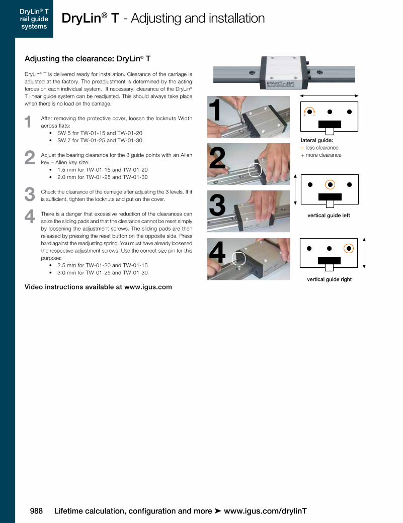
lateral guide: less clearance more clearance
Adjusting the clearance: DryLin® T
DryLin® T is delivered ready for installation. Clearance of the carriage is adjusted at the factory. The preadjustment is determined by the acting forces on each individual system. If necessary, clearance of the DryLin® T linear guide system can be readjusted. This should al ways take place when there is no load on the carriage.
1 After removing the protective cover, loosen the lock nuts Width across flats:
• SW 5 for TW-01-15 and TW-01-20
• SW 7 for TW-01-25 and TW-01-30
2 Adjust the bearing clearance for the 3 guide points with an Allen key – Allen key size:
• 1.5 mm for TW-01-15 and TW-01-20
• 2.0 mm for TW-01-25 and TW-01-30
3 Check the clearance of the carriage after adjusting the 3 levels. If it is sufficient, tighten the locknuts and put on the cover.
4 There is a danger that excessive reduction of the clearances can seize the sliding pads and that the clearance cannot be reset simply by loosening the adjustment screws. The sliding pads are then released by pressing the reset button on the opposite side. Press hard against the readjusting spring. You must have already loosened the re spec tive adjustment screws. Use the correct size pin for this purpose:
• 2.5 mm for TW-01-20 and TW-01-15 • 3.0 mm for TW-01-25 and TW-01-30
Video instructions available at www.igus.com

DryLin® T rail guide systems
9893D-CAD files, prices and delivery time ➤ www.igus.com/drylinT
DryLin® T - Adjusting and installation
1
2
3
locked
unlocked
Adjusting the clearance: DryLin® T Automatic
The DryLin® T Automatic series offers you an automatic adjustment of the clearance. A readjustment can take place automatically in steps of 0.1 mm. Springs tighten the regulating wedge immediately as soon as the clearance is bigger than 0.1 mm and the system is unloaded.
1 The system will be delivered with 3 keys and are necessary for mounting the carriage onto the rail. In case these keys are removed they need to be refitted into the openings and turned clockwise 90°.
2 After the carriage is on the rail, remove the keys by turning them counterclockwise 90° and pull out. The clearance will then be adjust-ed automatically.
3 You can remove the carriage at any time. In order to do so, simply plug the keys back into the carriage (see step 1).
990
DryLin® T rail guide systems
Lifetime calculation, configuration and more ➤ www.igus.com/drylinT
DryLin® T - Adjusting and installation
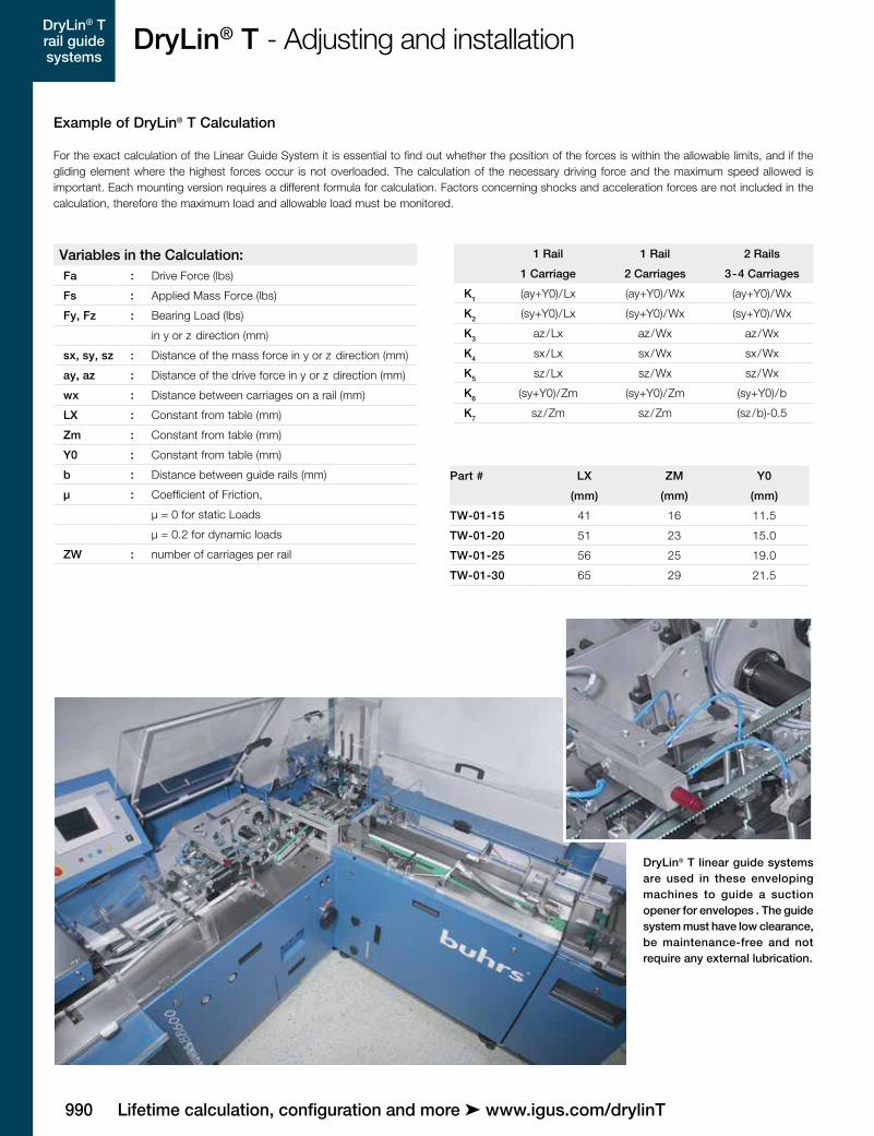
Part # LX ZM Y0
(mm) (mm) (mm)
TW-01-15 41 16 11.5
TW-01-20 51 23 15.0
TW-01-25 56 25 19.0
TW-01-30 65 29 21.5
1 Rail 1 Rail 2 Rails
1 Carriage 2 Carriages 3-4 Carriages
K1 (ay+Y0)/Lx (ay+Y0)/Wx (ay+Y0)/Wx
K2 (sy+Y0)/Lx (sy+Y0)/Wx (sy+Y0)/Wx
K3 az/Lx az/Wx az/Wx
K4 sx/Lx sx/Wx sx/Wx
K5 sz/Lx sz/Wx sz/Wx
K6 (sy+Y0)/Zm (sy+Y0)/Zm (sy+Y0)/b
K7 sz/Zm sz/Zm (sz/b)-0.5
Variables in the Calculation:Fa : Drive Force (lbs)
Fs : Applied Mass Force (lbs)
Fy, Fz : Bearing Load (lbs)
in y or z direction (mm)
sx, sy, sz : Distance of the mass force in y or z direction (mm)
ay, az : Distance of the drive force in y or z direction (mm)
wx : Distance between carriages on a rail (mm)
LX : Constant from table (mm)
Zm : Constant from table (mm)
Y0 : Constant from table (mm)
b : Distance between guide rails (mm)
µ : Coefficient of Friction,
µ = 0 for static Loads
µ = 0.2 for dynamic loads
ZW : number of carriages per rail
Example of DryLin® T Calculation
For the exact calculation of the Linear Guide System it is essential to find out whether the position of the forces is within the allowable limits, and if the gliding element where the highest forces occur is not overloaded. The calculation of the necessary driving force and the maximum speed allowed is important. Each mounting version requires a different formula for calculation. Factors concerning shocks and acceleration forces are not included in the calculation, therefore the maximum load and allowable load must be monitored.
DryLin® T linear guide systems are used in these enveloping machines to guide a suction opener for envelopes . The guide system must have low clearance, be maintenance-free and not require any external lubrication.

DryLin® T rail guide systems
9913D-CAD files, prices and delivery time ➤ www.igus.com/drylinT
DryLin® T rail guide systems
DryLin® T - System design
Table 03: maximum permissible load per sliding element
Part No. Fymax, Fzmax
[N]
TW-01-15 2,000
TW-01-20 3,700
TW-01-25 5,000
TW-01-30 7,000
TW-01-30
TW-01-25
TW-01-20
TW-01-15
2.0001.000100100,1
2,0
10,0
1,0
0,2
0,5
5,0
20 50 200 500
Diagram 04: Diagram to determine the maximum permissible speed for the calculated bearing load
Bearing load (center) [N]
Per
mis
sib
le m
ean
spee
d [m
/s]

992
DryLin® T rail guide systems
Lifetime calculation, configuration and more ➤ www.igus.com/drylinT
DryLin® T - Mounting version horizontal
Recommended Procedure:1st StepSelect the mounting version:
2nd StepCheck to see whether the maximum distances of the applied forces are within the permissible values (see Maximum permissible distances.)
Maximum permissible distances between acting forces:
Variation: 1 Rail, 1 Carriage sy + sz < 2 Lx - Y0
ay + az < 2 Lx - Y0
sy < 5 Zm
sz < 5 Zm
sx
ay
Faaz
yzx
Fssz
Zero Point
b
WX
ay
sx
sz
az
Fs
Fa
y
zx
Zero Point
Fixed Bearing
FloatingBearing
Variation: 1 Rail, 2 CarriagesVariation: 2 Rails, 4 Carriages sy + sz < 2 wx - Y0
ay + az < 2 wx - Y0
3rd Step:Calculate the necessary drive force
3.1 Center of gravity in x and z direction inside the carriage(s)
Fa1= µ
· Fs 1– 2µ K3
Fa2= 2µ K7 · Fs
1– 2µ K3
Fa3= 2µ K4 · Fs
1– 2µ K3– 2µ K1
3.2 Center of gravity in z direction outside of the carriage(s)
3.3 Center of gravity in x direction outside of the carriage(s)
If the position of the center of gravity is not specified: Fa = MAX (Fa1, Fa2, Fa3)
4th Step:Calculate the maximum bearing load
Fy max= 2Fs ( 2K4 + 0,5 ) • Zw Zw
4.1 Maximum bearing load in the y direction 4.2 Maximum bearing load in the z direction
Fz max= 4Fa K3
Zw2(K7+ 0,5)+ 2Fa K1
Zw2
5th Step: Check calculated load for both y and z with table on page 990 - Maximum permissible load for Fy max & Fz max. This table illustrates the maximum permissible load on a single gliding element from the DryLin® T carriage. Evaluating the maximum load on a single gliding element establishes a safety
factor for the linear system. ➤ Page 990
6th Step: Determine the maximum permissible speed for the calculated load from Step No. 4 ➤ Page 990
● horizontal
1 rail and 1 carriage
1 rail and 2 carriages
2 rails and 4 carriages

DryLin® T rail guide systems
9933D-CAD files, prices and delivery time ➤ www.igus.com/drylinT
DryLin® T - Mounting version lateral
Recommended Procedure:
1st StepSelect the mounting version:
2nd StepCheck to see whether the maximum distances of the applied forces are within the permissible values (see Maximum permissible distances.)
Variation: 1 Rail, 1 Carriage
sy + sz < 2 Lx - Y0
ay + az < 2 Lx - Y0
sy < 5 Zm
sz < 5 Zm
Maximum permissible distances between acting forces:
sx
Fs
Fa
sy
ayaz
z
y
x
Zero Point
sx
Fs
b
WX
ay
az
sy
Fa
y
x
z
Zero Point
FixedBearing
FloatingBearing
Variation: 1 Rail, 2 CarriagesVariation: 2 Rails, 4 Carriages
sy + sz < 2 wx - Y0
ay + az < 2 wx - Y0
3rd Step:Calculate the necessary drive force
First, two calculations must be made:
The drive force Fa corresponds to the calculated maximum value
4th Step:Calculate the maximum bearing load
4.1 Maximum bearing load in the y direction 4.2 Maximum bearing load in the z direction
5th Step: Check calculated load for both y and z with table on page 990 - Maximum permissible load for Fy max & Fz max. This table illustrates the maximum permissible load on a single gliding element from the DryLin® T carriage. Evaluating the maximum load on a single gliding element establishes a safety
factor for the linear system. ➤ Page 990
6th Step: Determine the maximum permissible speed for the calculated load from Step No. 4 ➤ Page 990
● side-mounting
1 rail and 1 carriage
1 rail and 2 carriages
2 rails and 4 carriages
Fa1= (1+2 K6)µ
· Fs 1– 2µ K1
Fa2= (2 K4+2 K6)µ
· Fs 1– 2µ K1– 2µ K3
Fa = MAX (Fa1, Fa2)
Fz max= 2Fs ( 2K4 + 0.5 )+
4Fa K3
Zw Zw Zw2Fy max=
Fs K6 + 2Fa K1
Zw Zw2

994
DryLin® T rail guide systems
Lifetime calculation, configuration and more ➤ www.igus.com/drylinT
DryLin® T - Mounting version vertical
Recommended Procedure:1st StepSelect the mounting version:
2nd StepCheck to see whether the maximum distances of the applied forces are within the permissible values (see Maximum permissible distances.)
Variation: 1 Rail, 1 Carriage
sy + sz < 2 Lx - Y0
ay + az < 2 Lx - Y0
sy < 5 Zm
sz < 5 Zm
Maximum permissible distances between acting forces:
az
ay
sy
Fa
Fs x
yz
Zero Point
Variation: 1 Rail, 2 CarriagesVariation: 2 Rails, 4 Carriages
sy + sz < 2 wx - Y0
ay + az < 2 wx - Y0
4th Step:Calculate the maximum bearing load
4.1 Maximum bearing load in the y direction 4.2 Maximum bearing load in the z direction
5th Step: Check calculated load for both y and z with table on page 990 - Maximum permissible load for Fy max & Fz max. This table illustrates the maximum permissible load on a single gliding element from the DryLin® T carriage. Evaluating the maximum load on a single gliding element establishes a safety
factor for the linear system. ➤ Page 990
6th Step: Determine the maximum permissible speed for the calculated load from Step No. 4 ➤ Page 990
● vertical 1 rail and 1 carriage 1 rail and 2 carriages 2 rails and 4 carriages
Fs
b
WX
ay
az
sy
Fa
szy
x
z
Zero Point
FloatingBearing
Fixed Bearing
Fy max= Fa ay+Y0
– Fs K2 • 2 wx Zw2
3rd Step:Calculate the necessary drive force
First, four calculations must be made:
The drive force Fa corresponds to the calculated maximum value
Fa1= 2µ (sz+sy+Y0)–wx
· Fs 2µ (az+ay+Y0)–wx
Fa2= 2µ (–sz+sy+Y0)–wx
· Fs 2µ (–az+ay+Y0)–wx
Fa3= 2µ (sz–sy–Y0)–wx
· Fs 2µ (az–ay–Y0)–wx
Fa4= 2µ (sz+sy+Y0)+wx
· Fs 2µ (az+ay+Y0)+wx
Fa = MAX (Fa1, Fa2, Fa3, Fa4)
Fz max= Fa az
– Fs K5 • 4 wx Zw2