dry type catalogue final - delta star brochure for dry type... · transformer windings....
TRANSCRIPT

DRY-TYPE TRANSFORMERDRY-TYPE TRANSFORMER

CONTENTS
General DescriptionCore/Coil Assembly
insulation SystemEnclosures
TestsSpecifying the Transformers Needed
Selecting the Right TransformerSingle and Three- Phase Connections
Series and Multiple ConnectionsAutotransformers
Reduced Voltage AutostartersImportance of Sound Levels in Transformers
Wiring DiagramsTransformer Dimensions
Typical Core & Coil AssemblyDimensions: Single Phase Dry Type DimensionsDimensions: Three Phase Dry Type Dimensions
Losses of Dry Type TransformersInstruction Manual
1222333344456778889

1
GENERAL DESCRIPTION
ELTA STAR Dry Type Transformers are rated 600 volts and below for
supplying appliance, lighting and power loads from electrical distribution systems.
Capacity ratings are available from 5 to 1500 KVA. Standard distribution voltages
are 480 and 240 Volts; standard load voltages are 480, 380, 240, 208 and 120
volts. (However, other voltages as per customer's specifications can be made
available in a case to case basis). The transformer is used to match the load voltage
to the distribution voltage. Since no vaults are required for installation and they are
housed in free-standing enclosures, these transformers can be located right at the
load to provide the correct voltage for the application. This eliminates the need for
long, costly low voltage feeders.
Delta Star Transformers are designed, manufactured, and tested in
accordance with all applicable ANSI/NEMA & IIEE Standards.
All Delta Star Transformers are designed for continuous operation at rated
KVA, 24 hours a day, 365 days a year.
D

All insulation materials are flame-retardant and do not support combustion.
Transformers are insulated at 220°C with 150 rise. Required performances are obtained
without exceeding the above rise in a 40°C maximum 30°C average ambient temperature.
The enclosures are made of heavy gauge steel and are degreased, cleaned, primed, and
finished with gray color weather-resistant enamel.
On ventilated designs, the side enclosures are constructed with drip-proof louvers, with lifting
holes. This ensures easy heat dissipation . All ventilation openings are protected against falling dirts.
°C
Transformer cores are constructed with high
grade, non-aging, grain-oriented silicon steel with
high magnetic permeability and low hysteresis and
eddy current losses. Maximum magnetic flux
densities are substantially below the saturation
point. The core volume allows efficient transformer
operation at ten percent (10%) above the highest tap
voltage. The core laminations are tightly clamped
and compressed. Coils are wound of electrical grade
fiberglass-coated aluminum with continuous wound
construction. The coil assembly are impregnated
with a non-hydroscopic thermo setting varnish and
cured to reduce hotspots and seal out moisture.
Low core loss and winding loss are thus
guaranteed. (Refer to page 8 for transformer
losses).
2
CORE AND COIL ASSEMBLIES
INSULATION SYSTEM
ENCLOSURES

Transformer taps compensate for high or low line voltages. Standard three phase
taps are two (2) 5 percent taps below normal on all transformers. This arrangement
provides a 10-percent range of tap adjustment. However, voltage tap arrangement could
be designed as per customers' specifications.
The single-phase transformers can be connected as a three phase bank. Each
single phase transformer is rated one-third the bank KVA rating. See diagrams for typical
connections.
All transformers are equipped with a wiring compartment suitable for conduit entry
and large enough to allow convenient wiring. The maximum temperature of the enclosure
does not exceed 90° .
The core of the transformer is visibly grounded to the enclosure.
The following test are conducted on all transformers:
1. Ratio tests on the rated voltage connection and on all tap connections.2. Polarity and phase-relation tests on the rated voltage connection.3. Insulation resistance test.4. No-load and excitation current at rated voltage.5. Impedance measurement.
SPECIFYING THE TRANSFORMER NEEDED:?Determine the primary voltage – the source voltage presently available.?Determine the secondary voltage – the voltage needed at the load.?Determine the KVA load, allowing room for expansion.?For three phase transformers, determine connection vector
configuration.
Basically the above specifications are sufficient to determine the right transformer for your
need.
C
TESTS
THE FOLLOWING ITEMS MUST ALSO BE CONSIDERED IN SELECTING
THE RIGHT TRANSFORMER FOR YOUR PARTICULAR APPLICATION:
INPUT(PRIMARY)
OUTPUT(SECONDARY)
INPUT(PRIMARY)
OUTPUT(SECONDARY)
3 PHASE DELTA-WYE CONNECTIONS
SINGLE - AND THREE- PHASE CONNECTIONS
3

When three phase loads are to be supplied, single unit three-phase transformers should be
specified. Primary to secondary winding connections can be chosen on any of the following
configurations.
a) delta-wyeb) delta-deltac) wye-deltad) wye-wye
Please refer to wiring diagrams for single-phase and three-phase transformers on page 6.
For approximate weight and dimensions, refer to 7 & 8
Transformers with two (2) identical voltage (i.e., 120/240 or 120 x 240) may be
connected either in series or in parallel. Connected in series, the transformer will provide the
higher voltage (240 Volts); connected in parallel, the lower voltage (120 Volts) is obtained.
Over the past years, new electronic equipment have been studied to produce
harmonics that create non-linear current load which in turn generate extra heat in distribution
transformer windings.
Technically-designed K-Rated Transformers by Delta Star are available to efficiently supply power to such various electronic equipment and neutralizing the problem of overheating.
An auto transformer has only one (1) winding and therefore, is smaller and economical
than conventional two (2) winding transformers; they can be used in banks on three-phase
circuits or single phase to perform the same functions as transformers, with the exception of
two (2) isolating circuits. Single unit Three-phase auto transformers are available as well.
Auto transformers as motor starters are also available at 220 & 440V ratings. Voltage
taps are standard at 50%, 65% and 80%. Auto transformers with special voltages up to 4160V
can be fabricated upon customer's request.
SERIES AND MULTIPLE CONNECTIONS (SINGLE PHASE TRANSFORMERS ONLY)
AUTO TRANSFORMERS
K-RATED TRANSFORMERS
REDUCED VOLTAGE AUTOSTARTERS
4
All transformers make some sound… due to the vibration generated within the
magnetic steel core.
Fortunately, the noises in and around most locations – “the ambient sound level”
– usually mask transformer sounds if certain precautions are taken in selecting and in
installing the unit.
Not all noise can be heard!
To illustrate: you are riding in your car, the radio and heater are on. Everything's
fine … no annoying rattles.
If you turn the heater off, you hear slight rattles and squeaks. If you turn the radio
off, you'll hear even more noises. The noises you hear were there all the time… which
brings us to an important truth about sound: only the loudest sounds are heard. Still not
convince? Shoot off cannon and drop a pin at the same time. Which do you hear? And yet
the pin did make a sound when it struck.
Let's illustrate this principle with transformers: a 50 db transformer located in a
60 db ambient noise level- say an office with typewriters chattering, telephones ringing –
wouldn't bother anyone. The office noises drown out the humming of the transformer.
But at night, the ambient sound level drops, and the humming becomes quite apparent.
Delta Star Transformers core are clamped tightly and coils are wound tightly. Thus
sound levels of Delta Star Transformers are guaranteed to conform with ANSI-C89
specifications.
IMPORTANCE OF SOUND LEVELS IN TRANSFORMERS
5

WIRING DIAGRAMS
6
4) Wye-delta
Diagram 4
1) Single-phase with taps
Diagram 1
3) Delta-delta
Diagram 3
2) Delta-wye
Diagram 2
5) Wye-wye
Diagram 5
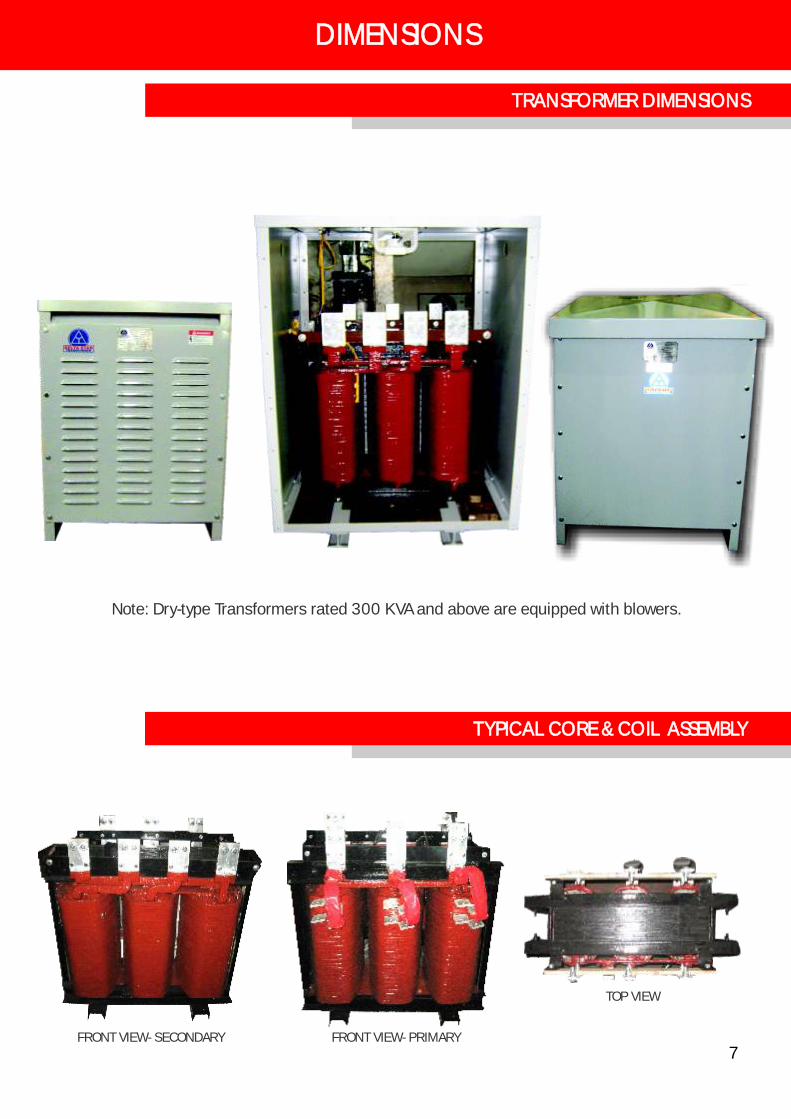
TYPICAL CORE & COIL ASSEMBLY
Note: Dry-type Transformers rated 300 KVA and above are equipped with blowers.
TOP VIEW
7
TRANSFORMER DIMENSIONS
DIMENSIONS
FRONT VIEW- SECONDARY FRONT VIEW- PRIMARY
7

TOTAL LOSSES
WINDING LOSSES
NO LOAD LOSSES
1000
100 200 300 400 500
2000
3000
4000
5000
6000
7000
8000
RATED CAPACITY (KVA)
LOSSES(WATTS)
LOSSES OF DRY TYPE TRANSFORMERS
DIMENSIONS
8
Approx. Approx.Net Wt. Net Wt.in kgs. in kgs.
5 45 6 12 12 5 45 16 22 127.5 55 18 14 14 7.5 55 18 21 1310 65 20 15 15 10 65 18 22 1415 80 24 17 17 15 80 20 22 1520 90 26 18 18 20 90 21 23 1625 115 28 20 20 25 115 23 23 1630 135 32 20 20 30 135 31 24 1645 165 34 22 22 45 165 32 24 1850 195 34 22 22 50 195 32 24 1875 265 36 26 26 75 265 36 32 22
112.5 335 40 26 26 112.5 335 40 32 22150 440 46 30 30 150 440 46 35 24
225 570 48 32 32 225 570 48 38 25300 780 52 36 36 300 780 52 42 30
400 955 58 48 32500 1070 58 48 32750 1565 68 60 48
1000 1950 76 60 48
Length Width
SINGLE PHASE DRY TYPE TRANSFORMERS THREE PHASE DRY TYPE TRANSFORMERS
KVAApproximate Dimensions in Inches
Height Length Width
Approximate Dimensions in Inches
KVAHeight

9
A. INSPECTION
B. OPERATION
C. MAINTENANCE
When Delta Star Transformer is received, please check the following:
1. Whether the ratings on the nameplate such as the capacity, voltage, frequency, etc. are the same as those you requested.
2. Whether there are any damage caused during transport. If there exists a part which malfunctions, please contact immediately the agent where you purchased the transformers.
After wiring and installation have been completed, examine the following items prior to energizing the transformer:
1. Are the fuses/circuit breakers on the line side and load side adequate? 2. Measure the insulation resistance between primary and secondary,
primary to ground, and secondary to ground.3. Double check all connections, especially for short circuits and ground on
the load side.4. Is the grounding wire securely connected?5. Finally, check the connections of the high tension lines to the transformer
terminals, energize the transformer.6. Check the output voltage if the desired value is realized. Adjust the tap-changer
position accordingly until desired voltage is attained.7. Finally, load the transformer in possible increments.
Periodical maintenance should be conducted as follows:
1. Check abrasion of painted surface. Determine causes and remedy.2. Visual check / inspect for possible overheating sections of the coil and of the
other live parts. 3. Retighten bolts and units on primary and secondary terminals.4. Check whether the grounding wire is still securely fastened.5. Check insulation resistance.
INSTRUCTION MANUAL

?
?
?
?
DESIGN, INSTALLATION, TESTING COMMISSIONING OF INDOOR/OUTDOOR POWER SUBSTATIONSSERVICING & PREVENTIVE MAINTENANCE OF POWER SUBSTATIONS (TRANSFORMERS & SWITCHGEARS)INDUSTRIAL ELECTRICAL INSTALLATIONTECHNICAL CONSULTATION SERVICES
?
?
?
?
?
?
?
SUPPLY AND INSTALLATION OF POWER AND DISTRIBUTION TRANSFORMERSGENERAL REPAIR/RECONDITIONING OF POWER AND DISTRIBUTION TRANSFORMERSMANUFACTURING OF DRY-TYPE TRANSFORMERS AND MOTOR AUTO-STARTERSSUPPLY AND INSTALLATION OF POWER CAPACITORSHIGH VOLTAGE POWER FUSES, CUT-OUTS LIGHTNING, ARRESTERS, RELAYS, ETC.HIGH VOLTAGE POWER SWITCHES (AIR BREAK SWITCH, LOAD-BREAK SWITCH)REACTORS (AIR-CORE, IRON-CORE, SHUNT, CURRENT LIMITING, HARMONIC FILTER)
DELTA STAR
“ THE TRANSFORMER PEOPLE”
SALES
SERV ICES
RENTAL O F T RANSFORMERS
?
?
POWER TRANSFORMERS (UP TO 69,000V) • DISTRIBUTION TRANSFORMERSDRY TYPE TRANSFORMERS
DRY-TYPE TRANSFORMER(FROM 3KVA UP TO 2000KVA
DISTRIBUTION TRANSFORMER 3 PHASE POWER TRANSFORMER(1MVA TO 20 MVA)
24 Hrs. SERVICE REYNALDO C. DAQUIGANProfessional Electrical Engineer
DELTA STAR
RENTAL
?
?
CRANE RENTAL Telescopic 20 Tones & 5 TonsANTI-ELECTRIC MANLIFT (200kg Max)
?
?
?
?
?
?
?
?
?
?
POWER FACTOR INSULATION TESTERDC HYPOT TESTER (80 KV)H.V. MEGGER TESTER (10 KV)TRANSFORMER TURN-RATIO (TTR) TEST
SETAUTOMATIC OIL DBV TESTER (60 KV)RELAY CALIBRATION TESTERLOW RESISTANCE OHMMETEREARTH/GROUND RESISTANCE TESTEROIL FILTER PRESS/ PURIFIERSERVICE GENERATOR
1613 Samuel St., Jordan Plaines, Novaliches Proper, Quezon CityDelta Star Power Manufacturing Corp.
CALL: 939-5431(PRIVATE EXCHANGE CONNECTING ALL DEPARTMENTS)
OR CALL: 936-8621 • 937-1181 •939-5432 TO 34FAX NO. 939-0278 CELLULAR: (0918) 901-0023
email: [email protected] Star Power Engineering
•Substation Engineers • Transformers • Consultants
C OMP LET E L INE O F T ES T ING
INSTRUMENT S