drum machine - massachusetts institute of...
TRANSCRIPT
DRUM MACHINE
ABSTRACT
This document describes the design, implementation, testing, and final results of a digital drum machine. The drum machine allows the user to compose percussive rhythms from a sound bank of audio samples. The user can determine which sounds to play at which points in time by using a series of switches to program a drum loop. This drum loop is played through the labkit speakers and visualized on a Video Graphics Array (VGA) display. The drum machine was coded in verilog in a Xilinx Integrated Software Environment and implemented on a Xilinx Field Programmable Gate Array (FPGA).
M A S S A C H U S E T T S I N S T I T U T E O F T E C H N O L O G Y 6 . 1 1 1 I N T R O D U C T O R Y D I G I T A L S Y S T E M S
L A B O R A T O R Y S P R I N G 2 0 0 6
H A N A L . A D A N I Y A S H I R L E Y S . F U N G
M A Y 1 8 , 2 0 0 6

6.111 Final Project DRUM MACHINE Adaniya, Fung Page i
C O N T E N T S
Abstract ...................................................................................................................................................................................... 1 1 Design Overview ............................................................................................................................................................. 1 2 Design Strategy................................................................................................................................................................. 2 3 Module Description and Implementation ................................................................................................................... 3
3.1 Synchronizer/Debouncer......................................................................................................................................... 4 3.2 Digital Clock Manager (DCM) ................................................................................................................................ 4 3.3 Beats Per Minute (BPMenable) ............................................................................................................................... 4 3.4 Parameters................................................................................................................................................................... 6 3.5 Display – VGACount, Displaynames, Letterdisplay, Letterselect, Binary8toBCD, Playstopdisplay, Blocks, and FFT Display..................................................................................................................................................... 7
3.5.1 VGAcount.v ..................................................................................................................................................... 8 3.5.2 Displaynames.v................................................................................................................................................. 8 3.5.3 Letterdisplay.v................................................................................................................................................... 8 3.5.4 Letterselect.v ..................................................................................................................................................... 8 3.5.5 Binary8toBCD.v............................................................................................................................................... 8 3.5.6 Playstopdisplay.v .............................................................................................................................................. 9 3.5.7 Blocks.v ............................................................................................................................................................. 9 3.5.8 FFTdisplay.v ..................................................................................................................................................... 9
3.6 Major FSM – enableminors.v................................................................................................................................... 9 3.7 Audio – Minor FSMs/memory interface (snarefsm.v, countersnare.v) & Audio.v ........................................ 9
3.7.1 SnareFSM.v..................................................................................................................................................... 10 3.7.2 Countersnare.v ............................................................................................................................................... 10 3.7.3 Snare ROM ..................................................................................................................................................... 10 3.7.4 Audio.v ............................................................................................................................................................ 11
3.8 Audio Mixer – mixer.v ............................................................................................................................................ 11 3.9 Fast Fourier transform (FFTcontroller.v)............................................................................................................ 12
4 Testing and Debugging................................................................................................................................................. 12 4.1 Simulated Waveforms ............................................................................................................................................. 12 4.2 Audio Debugging..................................................................................................................................................... 12 4.3 Clock Syncrhonization Bug.................................................................................................................................... 12 4.4 Display Glitches ....................................................................................................................................................... 13 4.5 FFT Bug .................................................................................................................................................................... 13 4.6 VGA (vgacount.v, hcount.v and vcount.v).......................................................................................................... 13
5 Future Work ................................................................................................................................................................... 13 6 Acknowledgements ....................................................................................................................................................... 13 7 Works Cited .................................................................................................................................................................... 14
6.111 Final Project DRUM MACHINE Adaniya, Fung Page ii
F I G U R E S
Figure 1. Visualization of the user interface. [S] ......................................................................................................... 1 Figure 2. Modular block diagram of the drum machine design. [S] ......................................................................... 2 Figure 3. Circuit diagram of toggle switches with LEDs. [S] .................................................................................... 4 Figure 4. Decoded signal for beat indicator generated from count16 by decoder4to16.v. [S] ............................ 5 Figure 5. Logic diagram of Parameter module. [H] .................................................................................................... 6 Figure 6. Play and stop finite state machine diagram. [S]........................................................................................... 7 Figure 7. Detailed modular diagram of the display components [S] ........................................................................ 7 Figure 8. State Transition Diagram of Minor FSM connected to initialized ROM. [H] ..................................... 10 Figure 9. Pipelined audio additive mixer architecture. [S]........................................................................................ 11 Figure 10. Letterselect module: pixel and line count request different letters for each text cell [H]................... 12
All figures listed above were created by Shirley S. Fung and Hana L. Adaniya unless otherwise noted.

6.111 Final Project DRUM MACHINE Adaniya, Fung Page 1
DRUM MACHINE
1 DESIGN OVERVIEW
The drum machine allows the user to compose rhythms from a sound bank of audio samples. The resulting loop is a combination of the sixteen different audio channels containing sounds varying from a kick drum to a cymbal. Each channel can be programmed individually for different beats by selecting a particular pattern. The sixteen audio channels are then combined using additive mixing.
Each of the 16 channels is assigned with a one second 8-bit audio sample. All the samples are recorded at 48 kHz and stored in about 0.5 Megabytes of memory. The pattern has a template of sixteen 16th notes. A row of sixteen squares on the video interface represents the on/off state of each sixteenth note of a channel.
The user programs the different beats by using a group of buttons and switches. The user can select the channel to program with a series of four switches on the lab kit, while a row of sixteen toggle switches will set the on-off states of each sixteenth note for that channel. As a quick way to clear all the channels, the drum machine supports a reset button. As the user changes the current pattern, the drum machine has the ability to revert back to a previously stored pattern.
The design of the drum machine was split into several different components that separately deal with the storage of the user-programmed patterns, the audio component, the beat keeping, and the display. The parameters module is the memory unit that stores the state information of the different patterns for each channel. The information is stored in an array of state registers visualized in the display portion of the project (see Figure 1). The parameters module also serves as an interface with the user to change the stored patterns for each sound.
Figure 1. Visualization of the user interface. [S]
The task of keeping the beat of the combined patterns falls to the counter element. The beats per minute at which the counter runs can be adjusted by the user. The audio portion of the final project includes both the actual memory storage of the audio samples in block RAM as well as a memory interface that can read the data

6.111 Final Project DRUM MACHINE Adaniya, Fung Page 2 from the memory. The display components include interfaces with all the other modules as it displays the current state of the beat sequence, the name of the audio sample as well as the overall beats per minute (BPM) and the Fourier Transform (FFT) of the master output audio signal. A visualization of the display as well as the block diagram for the drum machine can be seen in Figures 1 and 2 respectively. Each of the different modules in the block diagram will be discussed in greater detail in the following section.
The various internal subsystems will be described in detail in the next section. Each module is implemented in Verilog using the Xilinx Integrated Software Environment. A subset of the modules is then tested using ModelSim by generating behavioral waveforms. In the last section, the various advantages and shortcomings of the design will be discussed. Based on the current design, future recommendations will be made. All source code is attached in the Appendix. [H]
Figure 2. Modular block diagram of the drum machine design. [S]
2 DESIGN STRATEGY
The project began with a detailed block diagram of the drum machine system (see Figure 2). The initial block diagram divided the project into a series of modules. The modular design allowed for the change of one module without affecting the others. In addition, the modularity of the design facilitated the division of labor between the two lab partners. The design consisted of a major finite state machine (FSM), written by one lab partner, which sent start signals to a series of minor FSMs which were written by the other lab partner.
The original design stored the sixteen audio signals in an external SRAM. However, the design evolved into storing the sixteen audio signals in separate block RAMs for the benefit of a simpler memory interface. Each of the block RAMs were read by a separate FSM. These constituted the minor FSMs controlled by the major FSM discussed above.
The change in design strategy stemmed from adjustments in the audio signal storage. Instead of using sixteen bits to encode the audio signal, the audio files only required eight bits of precision. This reduction in memory
6.111 Final Project DRUM MACHINE Adaniya, Fung Page 3 usage allowed the project to use on-chip block RAM whereas the original design would have exceeded the capacity of the on-chip memory. [H]
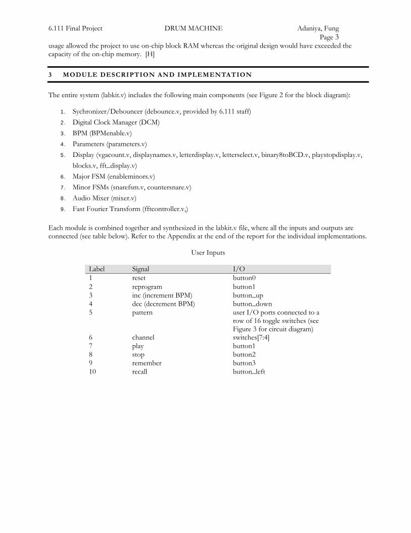
3 MODULE DESCRIPTION AND IMPLEMENTATION
The entire system (labkit.v) includes the following main components (see Figure 2 for the block diagram):
1. Sychronizer/Debouncer (debounce.v, provided by 6.111 staff) 2. Digital Clock Manager (DCM) 3. BPM (BPMenable.v) 4. Parameters (parameters.v) 5. Display (vgacount.v, displaynames.v, letterdisplay.v, letterselect.v, binary8toBCD.v, playstopdisplay.v,
blocks.v, fft_display.v) 6. Major FSM (enableminors.v) 7. Minor FSMs (snarefsm.v, countersnare.v) 8. Audio Mixer (mixer.v) 9. Fast Fourier Transform (fftcontroller.v,)
Each module is combined together and synthesized in the labkit.v file, where all the inputs and outputs are connected (see table below). Refer to the Appendix at the end of the report for the individual implementations.
User Inputs
Label Signal I/O 1 reset button0 2 reprogram button1 3 inc (increment BPM) button_up 4 dec (decrement BPM) button_down 5 pattern user I/O ports connected to a
row of 16 toggle switches (see Figure 3 for circuit diagram)
6 channel switches[7:4] 7 play button1 8 stop button2 9 remember button3 10 recall button_left

6.111 Final Project DRUM MACHINE Adaniya, Fung Page 4
Figure 3. Circuit diagram of toggle switches with LEDs. [S]
3.1 SYNCHRONIZER/DEBOUNCER
In order to deal with asynchronous inputs, the debouncer module uses a delay to register a noisy input, and synchronize it with the pixel clock generated by the DCM module from the 27 MHz clock on the lab kit. The user input buttons are all connected to an individual debouncer module. Because these user inputs are asynchronous, it may lead to problems with metastability if the transition occurs too close to a rising clock edge. Asynchronous inputs can also cause glitches and lead to unexpected results with the internal logic. If an external signal is not clocked, the sequential system cannot guarantee that setup and hold times will be met. By allowing the signal to settle, the possibility of causing metastability in the system can be dramatically mitigated.
The delay programmed in the debouncer module solves the problem with “bouncy” on/off signals inherent with mechanical buttons where the signal may take some time to settle. By making sure that the signal is stable for 0.01 seconds (as specified by the 6.111 staff), the synchronous input signal from the buttons can then be registered and retrieved by other modules.
Additionally, a debouncer module for 16 inputs was made for the row of 16 toggle switches. [S]
3.2 DIGITAL CLOCK MANAGER (DCM)
The DCM module allows the FPGA to create a faster digital clock than the one provided on the lab kit. The clock provided on the lab kit (27 MHz) was not fast enough to provide a frequency to support a 60 Hz refresh rate of the screen. Using the DCM code provided by the 6.111 staff in the lab4_labkit.v template on the course website, the lab kit now has a pixel_clock signal (25.175 MHz) that goes to all modules in the design. The DCM module takes the original clock on the lab kit, and multiplies the frequency by 27, and divides by 29. [S]
DCM pixel_clock_dcm (.CLKIN(clock_27mhz), .CLKFX(pclk)); // synthesis attribute CLKFX_DIVIDE of pixel_clock_dcm is 29 // synthesis attribute CLKFX_MULTIPLY of pixel_clock_dcm is 27 // synthesis attribute CLKIN_PERIOD of pixel_clock_dcm is 37 // synthesis attribute CLK_FEEDBACK of pixel_clock_dcm is "NONE"
3.3 BEATS PER MINUTE (BPMENABLE)
The counter module plays the important role of keeping the beat of the musical pattern. The counter runs while in the playing state at the beats per minute specified by the user. The counter is also connected to the parameter module in order to find out which audio signals to play at a certain time, as set by the user programmed pattern. The parameter module stores the user-pattern information and then allows the system to know which samples are set to high for a certain point in time. For the samples that are programmed to be
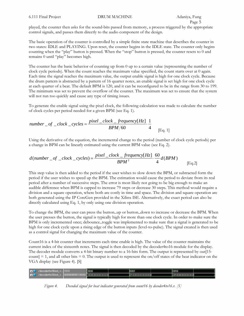
6.111 Final Project DRUM MACHINE Adaniya, Fung Page 5 played, the counter then asks for the sound-bits passed from memory, a process triggered by the appropriate control signals, and passes them directly to the audio component of the design.
The basic operation of the counter is controlled by a simple finite state machine that describes the counter in two states: IDLE and PLAYING. Upon reset, the counter begins in the IDLE state. The counter only begins counting when the “play” button is pressed. When the “stop” button is pressed, the counter resets to 0 and remains 0 until “play” becomes high.
The counter has the basic behavior of counting up from 0 up to a certain value (representing the number of clock cycle periods). When the count reaches the maximum value specified, the count starts over at 0 again. Each time the signal reaches the maximum value, the output enable signal is high for one clock cycle. Because the drum pattern is abstracted by a pattern of 16 quarter notes, an enable signal is set high for one clock cycle at each quarter of a beat. The default BPM is 120, and it can be reconfigured to be in the range from 30 to 199. The minimum was set to prevent the overflow of the counter. The maximum was set to ensure that the system will not run too quickly and cause any type of timing issues.
To generate the enable signal using the pixel clock, the following calculation was made to calculate the number of clock cycles per period needed for a given BPM (see Eq. 1).
_ _ [ ] 1_ _ _60 4
pixel clock frequency Hznumber of clock cyclesBPM
= ⋅ [Eq. 1]
Using the derivative of the equation, the incremental change to the period (number of clock cycle periods) per a change in BPM can be linearly estimated using the current BPM value (see Eq. 2).
2
_ _ [ ] 60( _ _ _ ) ( )4
pixel clock frequency Hzd number of clock cycles d BPMBPM
= ⋅ [Eq.2]
This step value is then added to the period if the user wishes to slow down the BPM, or subtracted form the period if the user wishes to speed up the BPM. The estimation would cause the period to deviate from its real period after a number of successive steps. The error is most likely not going to be big enough to make an audible difference when BPM is capped to increase 79 steps or decrease 30 steps. This method would require a division and a square operation, where both are costly in time and space. The division and square operation are both generated using the IP CoreGen provided in the Xilinx ISE. Alternatively, the exact period can also be directly calculated using Eq. 1, by only using one division operation.
To change the BPM, the user can press the button_up or button_down to increase or decrease the BPM. When the user presses the button, the signal is typically high for more than one clock cycle. In order to make sure the BPM is only incremented once; debounce_toggle was implemented to make sure that a signal is generated to be high for one clock cycle upon a rising edge of the button inputs (level-to-pulse). The signal created is then used as a control signal for changing the maximum value of the counter.
Count16 is a 4-bit counter that increments each time enable is high. The value of the counter maintains the current index of the sixteenth notes. The signal is then decoded by the decoder4to16 module for the display. The decoder module converts a 4-bit binary number to a 16-bits form. The output is represented by out[15-count] = 1, and all other bits = 0. The output is used to represent the on/off states of the beat indicator on the VGA display (see Figure 4). [S]
Figure 4. Decoded signal for beat indicator generated from count16 by decoder4to16.v. [S]
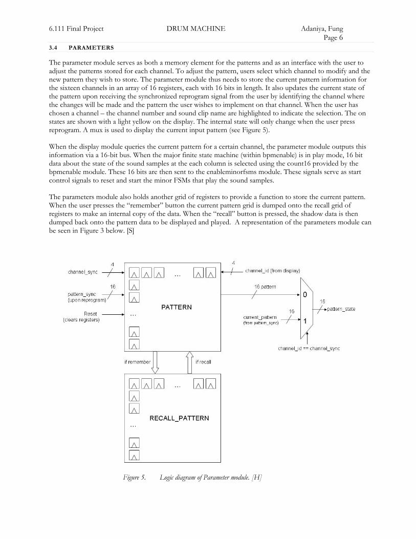
6.111 Final Project DRUM MACHINE Adaniya, Fung Page 6 3.4 PARAMETERS
The parameter module serves as both a memory element for the patterns and as an interface with the user to adjust the patterns stored for each channel. To adjust the pattern, users select which channel to modify and the new pattern they wish to store. The parameter module thus needs to store the current pattern information for the sixteen channels in an array of 16 registers, each with 16 bits in length. It also updates the current state of the pattern upon receiving the synchronized reprogram signal from the user by identifying the channel where the changes will be made and the pattern the user wishes to implement on that channel. When the user has chosen a channel – the channel number and sound clip name are highlighted to indicate the selection. The on states are shown with a light yellow on the display. The internal state will only change when the user press reprogram. A mux is used to display the current input pattern (see Figure 5).
When the display module queries the current pattern for a certain channel, the parameter module outputs this information via a 16-bit bus. When the major finite state machine (within bpmenable) is in play mode, 16 bit data about the state of the sound samples at the each column is selected using the count16 provided by the bpmenable module. These 16 bits are then sent to the enableminorfsms module. These signals serve as start control signals to reset and start the minor FSMs that play the sound samples.
The parameters module also holds another grid of registers to provide a function to store the current pattern. When the user presses the “remember” button the current pattern grid is dumped onto the recall grid of registers to make an internal copy of the data. When the “recall” button is pressed, the shadow data is then dumped back onto the pattern data to be displayed and played. A representation of the parameters module can be seen in Figure 3 below. [S]
Figure 5. Logic diagram of Parameter module. [H]
6.111 Final Project DRUM MACHINE Adaniya, Fung Page 7 3.5 DISPLAY – VGACOUNT, DISPLAYNAMES, LETTERDISPLAY, LETTERSELECT,
BINARY8TOBCD, PLAYSTOPDISPLAY, BLOCKS, AND FFT DISPLAY
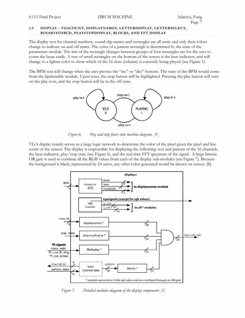
The display text for channel numbers, sound clip names and rectangles are all static and only their colors change to indicate on and off states. The color of a pattern rectangle is determined by the state of the parameters module. The tint of the rectangle changes between groups of four rectangles are for the user to count the beats easily. A row of small rectangles on the bottom of the screen is the beat indicator, and will change to a lighter color to show which of the 16 slots (column) is currently being played (see Figure 1).
The BPM text will change when the user presses the “inc” or “dec” buttons. The state of the BPM would come from the bpmenable module. Upon reset, the stop button will be highlighted. Pressing the play button will turn on the play icon, and the stop button will be in the off state.
Figure 6. Play and stop finite state machine diagram. [S]
VGA display mainly serves as a large logic network to determine the color of the pixel given the pixel and line count of the screen. The display is responsible for displaying the following: text and pattern of the 16 channels, the beat indicator, play/stop state (see Figure 6), and the real time FFT spectrum of the signal. A large bitwise OR gate is used to combine all the RGB values from each of the display sub-modules (see Figure 7). Because the background is black, represented by 24 zeros, any other color generated would be shown on screen. [S]
Figure 7. Detailed modular diagram of the display components [S]
6.111 Final Project DRUM MACHINE Adaniya, Fung Page 8
3.5.1 VGACOUNT.V
The VGA controller, implemented in problem set 3, follows the specification described in Figure 6 of the lab 4 handout provided by the 6.111 staff. The specification show video timing for a 640x480 resolution. Using a 25.175 MHz pixel clock, a 60 Hz refresh rate can be generated. The hcount and vcount modules are both implemented using counters, where the output of blank and sync signals are determined by the value of the count. Upon reset, the count resets back to zero. For detailed description of the VGA block, refer to the VGA section of the lab 4 handout. [S]
3.5.2 DISPLAYNAMES.V
A significant section of the display lists the channel numbers and the names of the different sound clips the user can use to program the drum machine. The sample names on the display are static and utilize a specially created font. The module displaynames is the top level module that controls each character and its positioning on the screen.
The characters are created in the letterdisplay module and called up into their appropriate positions by the letterselect module. The purpose of the displaynames module is to interconnect the two submodules and pass down the pertinent inputs. The display names module inputs the pixel clock, pixel and line count, the channel_sync information required for the highlighting of the current row, as well as the beats per minute. The output of the module is simply the VGA (video graphics array) RGB values for the portion of the display that the module controls. The output RGB values will be ORed with the RGB values from the other modules that draw to the screen. [H]
3.5.3 LETTERDISPLAY.V
The letterdisplay module contains the logic that writes alphanumeric characters in text cells that are 8 pixels tall and 8 pixels wide. The alphanumeric characters were created by specifying the RGB output for each individual pixel in the 8x8 pixel text cell. The offset within each cell was calculated by finding the remainder of pixel and line count divided by 8.
An added feature allows the letterdisplay module to accept a highlight enable input. This signal when high will cause the letterdisplay module to highlight the specified text in a contrasting RGB color. This feature was used in order to highlight the row specified by the channel_sync switches to aid in usability by emphasizing which sample is currently being programmed. [H]
3.5.4 LETTERSELECT.V
The letter selection module divides the screen into a grid of 8 by 8 pixel squares. For each square, the programmer can call up any of the alphanumeric characters defined in the letterdisplay module. This module takes the current pixel count and line count and maps them to the appropriate row and column and outputs the alphanumeric character that should be displayed in that square. This output request for a certain character is then wired to letterdisplay through the upper-level displaynames module.
The only non-static portions of the display are the font color and the BPM number display. The letterselect module originates the highlight enable signal by matching the row of text with the channel selection switches. The BPM translation from a three-digit number into the appropriate characters is discussed in section 3.5.5. [H]
3.5.5 BINARY8TOBCD.V
The BPM is indicated by a decimal number on screen. To convert from the binary number representation registered in the bpmenable module, a binary to binary coded decimal (BCD) converter is used. The algorithm uses the “shift and add-3” algorithm. The code and algorithm is adopted from: http://www.engr.udaton.edu/faculty/jloomis/ece314/. The BCD value is then fed into the letterselect module to be displayed. [S]

6.111 Final Project DRUM MACHINE Adaniya, Fung Page 9 3.5.6 PLAYSTOPDISPLAY.V
This module controls the display of the play and stop buttons on the VGA display. The module uses the play state input passed down from the BPM enable to determine the state of the color of the buttons. The play button is illuminated only if the play state signal is high, while the opposite is true for the stop button. The buttons were created much like the font, by specifying the RGB output for each individual pixel in a 16x16 pixel text cell. [H]
3.5.7 BLOCKS.V
To display the pattern grid, the display queries for the channel data by sending the channel id to the parameters module. The parameters module then return the 16 bit data representing the pattern programmed for that channel. The data for each of the channels is loaded during the line just before the row of 16 squares are drawn. The pattern data is then fed to the blocks module to be drawn. “On” squares are drawn with a slightly brighter color than the “off” squares to indicate the state. Columns of four are also drawn with a different shade to help the user mentally count the squares easier by grouping four columns together. In a similar fashion, the blocks.v module draws the beat indicator using the decoded count16 data. [S]
3.5.8 FFTDISPLAY.V
The display module is also responsible for calculating the magnitude of the signal for each of the 24 frequency bins shown on screen. The module should implement a FFT algorithm to determine the power versus
frequency graph for a signal. The magnitude is calculated by 2 2_ _fft real fft img+ . The square, sum, and square root operations are done through modules created using the IP CoreGen. The square root was initially avoided because of its high latency of 20 clock periods. However, the square root reduces the number of bits by half to represent the value at that bin. The operation helps to make the output number more manageable for the logic used to create bars to represent the magnitude. The end result was an 18-bit number where the last 8 bits were used to represent the height of the bar. The least significant bits were used because the value was never larger than 2^8. Each of these values are calculated sequentially when the line count is off screen. An entire line count period (800 pixel counts) is given for output of the magnitude calculations to be stable and correct. Consequently the FFT module should only updates the internal values at the refresh rate of the display (60 Hz). [S]
To display the height of the bar, the following pseudo code was used:
for (k = 0; k < 24; k = k + 1) if (p_cnt >= left_space + sq_width*k && p_cnt < left_space + sq_width*(k+1)) vga_out_rgb <= (l_cnt+fft_mag_sqrt_reg[k] >= bottom_space)? on : off;
3.6 MAJOR FSM – ENABLEMINORS.V
The FSM controllers that play the audio sample from the block RAMs run on the AC’97 bit clock, which runs at 24 MHz. On the other hand, the control signals from the major FSM are synchronous with the pixel clock, running at 25.175 MHz. In order to solve the problem of asynchronous signals, the enable signals for the minor FSMs are put into a pulse to level converter. Each of the one clock cycle pulses is converted to a high signal for three clock cycles. This mechanism ensures that the minor FSMs would catch the signal at least once and at most three times. Because the start signals merely reset the count for the address, catching the start signal for three times would not matter because the multiple read of address 0 of the block ram for 3 clock cycles would not be audible. [S]
3.7 AUDIO – MINOR FSMS/MEMORY INTERFACE (SNAREFSM.V, COUNTERSNARE.V) & AUDIO.V
The major FSM control 16 minor FSMs, one for each audio sample. The major-minor FSM abstraction facilitated the two clock regimes, making the abstraction an important design approach. The following section will discuss the snare audio clip, but a similar structure and counter is instantiated for all the 16 samples. Small adjustments are made in the code to suit the length of each sample by instantiating a different height of ROM and setting a different MAXCOUNT parameter in the counter. The top module (top.v) instantiates the

6.111 Final Project DRUM MACHINE Adaniya, Fung Page 10 different sub-modules related to audio and generates an enable signal for the minor FSMs at every rising edge of the audio sync signal (ac97_sync), a signal generated by the labkit to specify each frame (see Figure 8). [H]
3.7.1 SNAREFSM.V
The snarefsm as well as the other similar audio sample FSMs serve as minor FSMs which take in the start signals generated in the enableminors FSM and sends them to the memory interface. The memory interface is a counter FSM (countersnare.v) which reads data from the ROM (snare) sequentially. [H]
3.7.2 COUNTERSNARE.V
The counter functions as a memory interface by generating an incremental signal that serves as the address that is being read from memory. The counter module is a minor FSM with two states, a counting and a resting state. When the minor FSM receives a start signal from the major FSM (enableminors module), the counter moves into the COUNT state and increments its count value starting from zero. If uninterrupted, the minor FSM will stay in its COUNT state incremented the count value until it reaches the MAXCOUNT value set to be the length of the ROM. When it reaches the MAXCOUNT value, the counter transitions to the REST state and awaits the next start signal.
If the counter receives a second start signal while in any state, it will immediately revert to t he initial COUNT state with count value equal to zero. This feature is essential in the way the drum machine deals with consecutive beats which are too close together to allow the entire audio sample to play. This module signifies that if a second beat is called for, the first audio sample will be chopped off and will start over again from the beginning. A state transition diagram for the minor FSM can be seen in Figure 8 below. [H]
Figure 8. State Transition Diagram of Minor FSM connected to initialized ROM. [H]
3.7.3 SNARE ROM
6.111 Final Project DRUM MACHINE Adaniya, Fung Page 11 The ROM (read-only memory) is instantiated as IP CoreGen Block RAM. It accepts as inputs an address and a clock and outputs the data stored at that address. The Block ROM for all the samples is 8 bits wide and a variable number of bits long. The snare ROM for example contained 3999 lines of PCM data and thus is addressed by 12 bits. The counter module described above thus has its MAXCOUNT set to equal the length of the ROM so that the entire memory is read out and passed to the minor FSM and on to the audio codec for output to the speakers. [H]
3.7.4 AUDIO.V
The audio.v module is adapted from the digital loopback code presented in Christopher Falling and Nathan Ickes’ AC’97 tutorial. The adjustments allowed the LM4550 implementation of the AC’97 codec to input a sample from memory as the left and right channel PCM data. The AC’97 codec accepts PCM (pulse code modulation) signal, a digital representation of an analog signal, encoded to a 20 bit two’s complement value. The LM4550 implementation only uses the 18 most significant bits, and moreover the audio files stored and sent to the audio.v module as samples were only 8 bits wide, as discussed in the memory section of this report. [H]
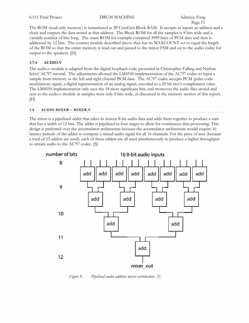
3.8 AUDIO MIXER – MIXER.V
The mixer is a pipelined adder that takes in sixteen 8-bit audio data and adds them together to produce a sum that has a width of 12 bits. The adder is pipelined in four stages to allow for continuous data processing. This design is preferred over the accumulator architecture because the accumulator architecture would require 16 latency periods of the adder to compute a mixed audio signal for all 16 channels. For the price of area (because a total of 15 adders are used), each of these adders are all used simultaneously to produce a higher throughput to stream audio to the AC’97 codec. [S]
Figure 9. Pipelined audio additive mixer architecture. [S]

6.111 Final Project DRUM MACHINE Adaniya, Fung Page 12 3.9 FAST FOURIER TRANSFORM (FFTCONTROLLER.V)
The IP CoreGen provided by Xilinx calculates the real and imaginary parts of the audio signal. The 12-bit mixer output is used as the real part of the signal as the input to the FFT module. The FFT module is used in the pipelined streaming I/O mode, where inputs are internally registered so that frames of data are calculated and unloaded continuously. The output is unscaled and not truncated at the various stages of arithmetic. Because the design of the project is not constrained by the area (the Virtex II has more than enough room to fit our application), this pipelined architecture is chose over other alternatives, such as Radix-4 and Radix-2, which both uses less area. The trade off is done for simplicity of the FFT controller interface. [S]
4 TESTING AND DEBUGGING
Testing and debugging began during the initial stages of the project. It involved generating ModelSim waveforms as well as several adjustments to parameters along with other methods of tracking down and fixing bugs. [H]
4.1 SIMULATED WAVEFORMS
Several of the basic modules were tested by creating verilog test benches within the project itself. ModelSim displayed the generated waveforms allowing the programmer to observe the simulated behavior of the module. Figure 10 shows the generated waveforms for the letterselect module. The fourth signal on the waveform demonstrates how the different letters on the display are being selected by the letterselect module. Several of the other modules, including the memory interface counters and the letter display, were also designed with accompanying test benches. [H]
Figure 10. Letterselect module: pixel and line count request different letters for each text cell [H]
4.2 AUDIO DEBUGGING
A sine wave was generated and used to test the audio component of the drum machine. Using a known signal allowed the programmer to verify that the audio sounds were being loaded and accessed as expected from CoreGen’s instantiated Block ROM. The sine wave was also used for testing the FFT module to verify that the correct Fourier Transform was being calculated from the audio signal. [H]
4.3 CLOCK SYNCRHONIZATION BUG
One of the easiest bugs to catch was the clock synchronization bug. Upon connecting the audio components to the rest of the drum machine, a problem arose from the use of two different clocks. The audio component of the drum machine utilized the ac97_bit_clk, a 24 Mhz clock generated specifically for use by the AC’97 codec, while the rest of the modules operated off the pixel_clock which ran at 24.175 MHz. The audio components were prone to miss some of the start signals generated in the pixel clock regime leading due to the asynchronous clocks. A solution to this problem was to hold the start signals generated by the Major FSMS to the minor FSMs running in the ac97_bit_clk domain high for three clock cycles. Running the two separate clocks demonstrated the complications of asynchronous systems. [H]
6.111 Final Project DRUM MACHINE Adaniya, Fung Page 13 4.4 DISPLAY GLITCHES
With the addition of a large amount of logic from the alphanumeric characters, the display became glitchy. A solution for this problem was to slow down the pixel clock thus changing the refresh rate from the standard 75 Hz to a lower frequency of 60 Hz. This change gave the display module more time to calculate the logic and cured the display of the glitches it was experiencing. [H]
4.5 FFT BUG
The initial FFT module used a transform length of 16 to calculate the real and imaginary parts of the mixed audio signal. However upon implementation, the transform length of 16 was found to be too coarse and that the energy of the signal was concentrated in the lower frequencies leading to only one of the 16 bars to register many changes in magnitude. A quick fix for this problem was to refine the FFT calculation using 256 bins and to display only the bottom 24. This change was very effective in improving the appearance of the FFT portion of the display. [H]
4.6 VGA (VGACOUNT.V, HCOUNT.V AND VCOUNT.V)
The timing signals for the VGA component was tested to determine whether the counter was working properly. The implementation was trivial because many other counters have already been implemented in previous lab exercises and problem sets. [S]
5 FUTURE WORK
The basic design of the pattern sequencer is scalable. It can be extended to include more grids to store the 16x16 bits of data for a pattern. A mega sequencer can be made to sequence grids of pattern, so that a more complicated audio percussion loop can be created. Such an extension would only require a mux to control which grid of register to use for the display and audio components. If the user can store different pattern grids, the user would be able to create a song that plays patternA patternA patternB patternC. A more complex user interface would be required to select a pattern to include in the mega-sequence.
The system is also capable of scaling to a larger bank of audio samples. To add a new sample, designers can simply instantiate a counter and a block ram for the audio sample. This is limited by the number of block rams that are built in the Virtex II FPGA (144). If the Virtex II runs out of room, other memory interfaces such as an external SRAM, or EEPROM can be used to hold more audio data.
The interface only allows for 16 samples to be used, and each of them is fixed to the channel. Alternatively, the mapping of the channel to an audio sample can be modified so that the user can reprogram different patterns to be used for a particular channel. This would require a decoder to take the desired set of audio samples and convert it to a set of appropriate enable signals to enable the corresponding minor finite state machines. This functionality would require additional user control inputs to allow the user to choose a different sample to be programmed in the channel.
Another feature can also be added to allow the user to record the audio loops. The output from the mixer can be sent to an audio recording device where the data can be captured. The recording device can also be a tape recorder, or a digital media device. The data can be recorded at the mixer output or using the audio output generated by the AC’97 codec. [S]
6 ACKNOWLEDGEMENTS
Shirley and Hana would like to acknowledge the Freesound Project (http://freesound.iua.upf.edu/index.php) as the source of the sound clips for each of the sixteen percussive instruments.
6.111 Final Project DRUM MACHINE Adaniya, Fung Page 14 We would like to thank Christopher Falling for his help with the audio components, and Gim Hom for his invaluable advice and his help with the user interface. We would also like to extend our appreciation to our Teaching Assistant Kyeong-Jae Lee for keeping the lab open late and helping us refine our design. Thanks to Professor Chandrakasan and rest of the staff for your expertise and assistance! [H & S]
7 WORKS CITED
6.111 Spring 2006 audio presentation by Christopher Falling and Nathan Ickes
6.111 Spring 2006 Lab 4 handout