driving a stepper motor based on the mc9s08qd4 and...
TRANSCRIPT
Freescale SemiconductorApplication Note
Document Number: AN3602Rev. 0, 4/2008
ContentsIntroduction . . . . . . . . . . . . . . . . . . . . . . . . . . . . . . . . . . . 1Stepper Motor Management . . . . . . . . . . . . . . . . . . . . . . 2Controlling the Stepper Based on an Input Signal (PWM)4Describing the Code . . . . . . . . . . . . . . . . . . . . . . . . . . . . 9How to Port the Code and Use other Devices. . . . . . . . 12Conclusions . . . . . . . . . . . . . . . . . . . . . . . . . . . . . . . . . . 13
Driving a Stepper Motor Based on the MC9S08QD4 and Other 8-bit FamiliesUsing Input Signals to Determine the Position of the Stepper Motorby: Francisco Ramirez
Mexico
1 IntroductionThis application note describes how to control a low current stepper motor using the MC9S08QD4. It also shows how to change the position of a stepper motor using the duty cycle variations from an external PWM by using an external reference voltage or an external modulated signal. It shows the reader an easy example of how to drive a low current stepper motor using a simple input signal with a low end S08 MCU.
The MC9S08QD4 is a low cost automotive microcontroller and can be applied to several applications using different input signals.
This application note briefly describes operating a stepper motor, how it works, and what is required to drive it. The document also establishes how the input signal is managed, implemented and used. An explanation of code compatibility with the MC9S08SG8 (automotive device) or to the MC9S08QG8 (consumer and industrial device) is in this application note.
123456
© Freescale Semiconductor, Inc., 3/2008. All rights reserved.

Stepper Motor Management
Available with this document is the software for this application note, AN3602SW.zip.
Figure 1. DEMO9S08QD4 Evaluation Board
Section 5, “How to Port the Code and Use Other Devices,” explains the structure of the code and how it can be ported to other similar MCUs, for example the MC9S08QG8 and the MC9S08SG8. The code described in this application note has been developed based on the DEMO9S08QD4 evaluation board shown in Figure 1.
2 Stepper Motor ManagementA stepper motor is a small brushless synchronous electric motor that can divide a full rotation into a large number of steps. If this motor is electronically commutated, the motor's position can be controlled with precision without any feedback mechanism.
Steppers exhibit more vibration than other motor types. The discrete step tends to snap the rotor from one position to another. This vibration can cause the motor to lose torque at some speeds. The effect can be mitigated by accelerating quickly through the problem speed range, physically dampening the system, or using a micro-stepping driver. Motors with a greater number of phases have a smoother operation than those with fewer phases.
There are two basic arrangements for the electromagnetic coils: bipolar and unipolar. This application note focuses on a bipolar motor.
A bipolar motor is built with two different coils named in this document as coil A and coil B. This is why this stepper motor has four different wires. Bipolar stepper motors operate differently from traditional DC motors. Stepper motors have multiple toothed electromagnets arranged around a central metal gear. The
Driving a Stepper Motor Based on the MC9S08QD4 and Other 8-bit Families, Rev. 0
Freescale Semiconductor2

Stepper Motor Management
electromagnets are energized by an external control circuit, such as a microcontroller. To make the motor turn, the following steps are required:
1. Coil A is connected to the power that makes the gear's teeth magnetically attracted to the electromagnet's teeth (Figure 2).
2. The gear's teeth are aligned to the first electromagnet. Next, they are aligned to the second electromagnet.(Figure 2).
3. Coil B is then turned on and coil A is turned off (Figure 3).4. The gear then rotates to be aligned with the next gear Figure 3.5. Repeat process described in previous steps
.
Figure 2. Stepper Motor Coil A
Each of these rotations is called a step. This is how the motor can be turned with a precise angle.
Figure 3. Stepper Motor Coil B
The main characteristics of the stepper motor used to implement this application is a maximum current consumption of 20 mA. The torque provided by the motor is small. The maximum static torque = 4 mNm, maximum dynamic torque = 1.3, mNm which is strong enough to move standard gauges. The S08
Driving a Stepper Motor Based on the MC9S08QD4 and Other 8-bit Families, Rev. 0
Freescale Semiconductor 3
Controlling the Stepper Based on an Input Signal (PWM)
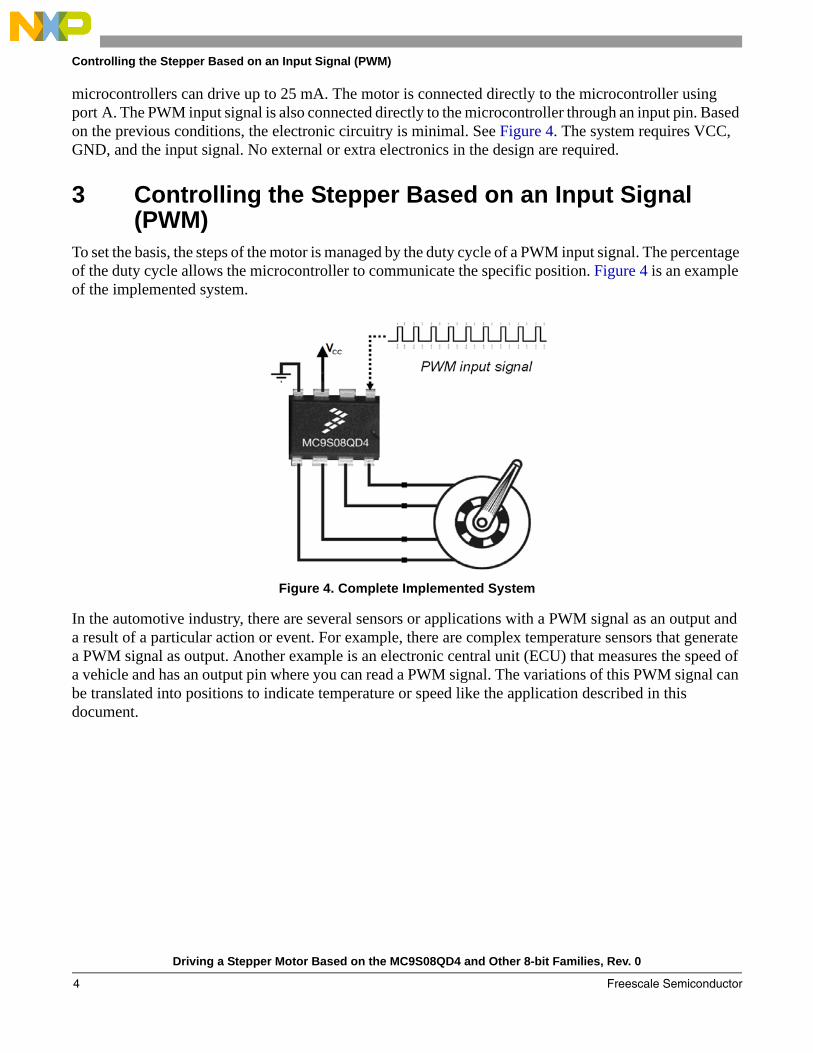
microcontrollers can drive up to 25 mA. The motor is connected directly to the microcontroller using port A. The PWM input signal is also connected directly to the microcontroller through an input pin. Based on the previous conditions, the electronic circuitry is minimal. See Figure 4. The system requires VCC, GND, and the input signal. No external or extra electronics in the design are required.
3 Controlling the Stepper Based on an Input Signal (PWM)
To set the basis, the steps of the motor is managed by the duty cycle of a PWM input signal. The percentage of the duty cycle allows the microcontroller to communicate the specific position. Figure 4 is an example of the implemented system.
Figure 4. Complete Implemented System
In the automotive industry, there are several sensors or applications with a PWM signal as an output and a result of a particular action or event. For example, there are complex temperature sensors that generate a PWM signal as output. Another example is an electronic central unit (ECU) that measures the speed of a vehicle and has an output pin where you can read a PWM signal. The variations of this PWM signal can be translated into positions to indicate temperature or speed like the application described in this document.
Driving a Stepper Motor Based on the MC9S08QD4 and Other 8-bit Families, Rev. 0
Freescale Semiconductor4
Controlling the Stepper Based on an Input Signal (PWM)
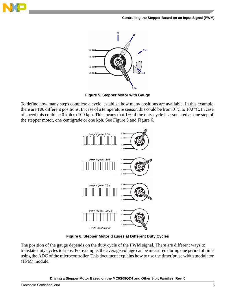
Figure 5. Stepper Motor with Gauge
To define how many steps complete a cycle, establish how many positions are available. In this example there are 100 different positions. In case of a temperature sensor, this could be from 0 °C to 100 °C. In case of speed this could be 0 kph to 100 kph. This means that 1% of the duty cycle is associated as one step of the stepper motor, one centigrade or one kph. See Figure 5 and Figure 6.
Figure 6. Stepper Motor Gauges at Different Duty Cycles
The position of the gauge depends on the duty cycle of the PWM signal. There are different ways to translate duty cycles to steps. For example, the average voltage can be measured during one period of time using the ADC of the microcontroller. This document explains how to use the timer/pulse width modulator (TPM) module.
Driving a Stepper Motor Based on the MC9S08QD4 and Other 8-bit Families, Rev. 0
Freescale Semiconductor 5

Controlling the Stepper Based on an Input Signal (PWM)
The code can take samples of the duty cycle and determine the percentage of the duty. As shown in Figure 7, PTA5 can be used with the TPM module configured as input capture. In this mode, the TPM2CH0I detects in rising-edge and falling-edge of all the changes of the input signal (Figure 8). These changes are stored as variables and then are calculated to produce the duty cycle. For details see the MC9S08QD4 Data Sheet.
Figure 7. MC9S08QD4 8-Pin Package
Below are the pin definitions described in code:/*********** Pin definitions ************* ***************************************** * PWM_INPUT PTAD5 - Pin 1 * * COIL_A1 PTAD0 - Pin 8 * * COIL_A2 PTAD1 - Pin 7 * * COIL_B1 PTAD2 - Pin 6 * * COIL_B2 PTAD3 - Pin 5 * *****************************************/
Figure 8. Input Signal Data Measurements
2
3
8
7
5
1
4
6
PTA5/TPM2CH0I/IRQ/RESET
VDD
VSS
8-pin AssignmentDIP/SOIC
PTA0/KBI1P0/TPM1CH0/ADC1P0
PTA1/KBI1P1/TPM1CH1/ADC1P1
PTA2/KBI1P2/TCLK1/ADC1P2
PTA3/KBI1P3/TCLK2/ADC1P3
PTA4/TPM2CH0O/BKGD/MS
Driving a Stepper Motor Based on the MC9S08QD4 and Other 8-bit Families, Rev. 0
Freescale Semiconductor6
Controlling the Stepper Based on an Input Signal (PWM)
The measured time between point 1 and point 2 is called a Frequency. The measured time between point 2 and point 3 is called Duty_Cycle_H. To find the duty cycle of the signal calculate:
Eqn. 1
After the duty cycle is calculated, the coils of the motor are controlled through port A, channels 0 to 3. As established previously there are one hundred positions available. This means that the required position is equal to the duty cycle.
Eqn. 2
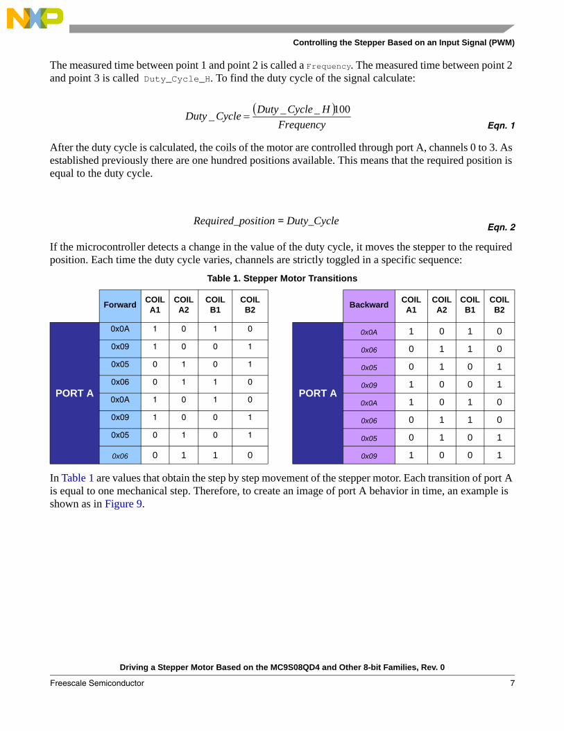
If the microcontroller detects a change in the value of the duty cycle, it moves the stepper to the required position. Each time the duty cycle varies, channels are strictly toggled in a specific sequence:
In Table 1 are values that obtain the step by step movement of the stepper motor. Each transition of port A is equal to one mechanical step. Therefore, to create an image of port A behavior in time, an example is shown as in Figure 9.
Table 1. Stepper Motor Transitions
Forward COIL A1
COIL A2
COIL B1
COIL B2 Backward COIL
A1COIL A2
COIL B1
COIL B2
PORT A
0x0A 1 0 1 0
PORT A
0x0A 1 0 1 00x09 1 0 0 1 0x06 0 1 1 00x05 0 1 0 1 0x05 0 1 0 10x06 0 1 1 0 0x09 1 0 0 10x0A 1 0 1 0 0x0A 1 0 1 00x09 1 0 0 1 0x06 0 1 1 00x05 0 1 0 1 0x05 0 1 0 1
0x06 0 1 1 0 0x09 1 0 0 1
( )Frequency
HCycleDutyCycleDuty 100___ =
Required_position = Duty_Cycle
Driving a Stepper Motor Based on the MC9S08QD4 and Other 8-bit Families, Rev. 0
Freescale Semiconductor 7

Describing the Code
Figure 9. Port A Outputs
To see how to move a stepper motor applying voltages to its coils see Figure 4. The process of synchronized signals moves the motor step by step while coil A and coil B are driven at different moments. When working with input voltages, frequency is similar to voltage reference height (VREFH) and the duty cycle is similiar to voltage variations measured in the ADC.
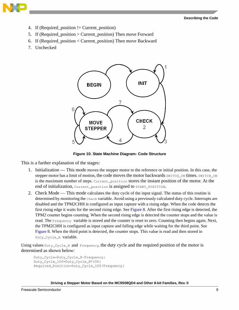
4 Describing the CodeThe code is based on the state machine diagram in Figure 10. Four main processes are described. Global constants and global variables are mentioned in this process. Constants are used to generalize the code and make changes faster. Variables are used to make specific calculations while the code is running and getting data from the ADC. They also track program stages.
Below are the constants and variables declared in the code:/* Global constants */#define SWITCH_ON 100 /* To know the steps to be in the first position */#define START_POSITION 0 /* Since it is limited to 100 degrees */#define CHECKED 1 /* To know if the frequency and duty cycle been checked */#define NOT_CHECKED 0 /* To know if the frequency and duty cycle been checked */#define Idle_DONE 5000 /* To know if the frequency and duty cycle been checked */
/* Global variables */unsigned int Current_position; /* Used to know the previous position of the stepper */unsigned int Required_Position; /* Used to know the new position of the stepper */unsigned int Frequency; /* Used to know the frequency of the PWM */unsigned int Duty_Cycle; /* Used to know the duty cycle of the PWM */unsigned int Duty_Cycle_100; /* Used to know the duty cycle of the PWM */unsigned int Duty_Cycle_H; /* Used to know the duty cycle of the PWM */unsigned int Check; /* Used to know the process status */unsigned int SWITCH, i; /* general use variable */
To help you understand the process below, there is a state diagram that represents the main loop of the system. See Figure 10:
1. Initialization2. Check mode3. If (Required_position == Current_position)
0x0A 0x06 0x05 0x09 0x0A 0x06 0x05 0x09
1
0
0 0 1
011
1 1 0 0
0 0 1 1
Coil A1
Coil A2
Coil B1
Coil B2
BusFrequency Cycle
n
Driving a Stepper Motor Based on the MC9S08QD4 and Other 8-bit Families, Rev. 0
Freescale Semiconductor8
Describing the Code
4. If (Required_position != Current_position)5. If (Required_position > Current_position) Then move Forward6. If (Required_position < Current_position) Then move Backward7. Unchecked
Figure 10. State Machine Diagram: Code Structure
This is a further explanation of the stages:1. Initialization — This mode moves the stepper motor to the reference or initial position. In this case, the
stepper motor has a limit of motion, the code moves the motor backwards SWITCH_ON times. SWITCH_ON is the maximum number of steps. Current_position stores the instant position of the motor. At the end of initialization, Current_position is assigned to START_POSITION.
2. Check Mode — This mode calculates the duty cycle of the input signal. The status of this routine is determined by monitoring the Check variable. Avoid using a previously calculated duty cycle. Interrupts are disabled and the TPM2CH0I is configured as input capture with a rising edge. When the code detects the first rising edge it waits for the second rising edge. See Figure 8. After the first rising edge is detected, the TPM2 counter begins counting. When the second rising edge is detected the counter stops and the value is read. The Frequency variable is stored and the counter is reset to zero. Counting then begins again. Next, the TPM2CH0I is configured as input capture and falling edge while waiting for the third point. See Figure 8. When the third point is detected, the counter stops. This value is read and then stored in Duty_Cycle_H variable.
Using values Duty_Cycle_H and Frequency, the duty cycle and the required position of the motor is determined as shown below:
Duty_Cycle=Duty_Cycle_H-Frequency;Duty_Cycle_100=Duty_Cycle_H*100;Required_Position=Duty_Cycle_100/Frequency;
Driving a Stepper Motor Based on the MC9S08QD4 and Other 8-bit Families, Rev. 0
Freescale Semiconductor 9

Describing the Code
At the end of the subroutine, the flag Check is set.3. If the Required_Position is equal to the Current_position, the code goes to idle until Idle_DONE is set.4. If the Required_Position is different than the Current_position, it is important to check if the difference
is bigger or smaller. This indicates if it needs to move forward or backwards.5. If the Required_Position is bigger than the Current_position, then the motor moves forward until both
variables are equal.— MOVE_STEPPER_FORWARD subroutine: When the Check flag is set as CHECKED, port A is set to: PTAD=0x0A; StateIdle(); PTAD=0x09; StateIdle(); PTAD=0x05; StateIdle(); PTAD=0x06; StateIdle();
PTAD=0x00; StateIdle(); Current_position++;
StateIdle routine is a counter to do a delay.
Established in Table 1 and Figure 9, the stepper motor moves forward (Required_Position - Current_position) times. Each time the motor moves, the movement is composed of four small steps of the stepper motor. Positions are multiplied by four steps in this example. This can be customized in the code as needed.
NOTEIf requiring fewer then four steps, obey Table 1 and Figure 9 sequences. To not miss the sequence, remember to store the last value in port A. Use the last used value as the last step to generate the next step.
6. If the Required_Position is smaller than the Current_position, the motor moves backwards until both variables are equal.— MOVE_STEPPER_BACKWARDS subroutine: When the Check flag is set as CHECKED port A is set to: PTAD=0x0A; StateIdle(); PTAD=0x06; StateIdle(); PTAD=0x05; StateIdle(); PTAD=0x09; StateIdle();
PTAD=0x00; StateIdle(); Current_position--;
As established in Table 1 and Figure 9 the stepper motor moves backwards (Current_position - Required_Position) times.
Driving a Stepper Motor Based on the MC9S08QD4 and Other 8-bit Families, Rev. 0
Freescale Semiconductor10

How to Port the Code and Use Other Devices
NOTEIf requiring fewer then four steps, obey Table 1 and Figure 9 sequences. To not miss the sequence, remember to store the last value in port A. Use this value as the last step to generate the next step.
7. Unchecked — When stages 5 and 6 are done and the Check flag is set as NOT_CHECKED the process goes into an infinite-loop from stages 3 to 7.
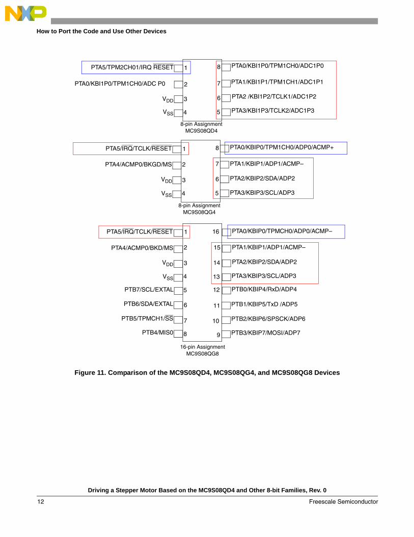
5 How to Port the Code and Use Other DevicesBelow is a comparison of the MC9S08QG4, the MC9S08QG8, and the MC9S08QD4 pinouts and their subtle differences. These must be considered when migrating between these devices.
Driving a Stepper Motor Based on the MC9S08QD4 and Other 8-bit Families, Rev. 0
Freescale Semiconductor 11
How to Port the Code and Use Other Devices
Figure 11. Comparison of the MC9S08QD4, MC9S08QG4, and MC9S08QG8 Devices
2
3
8
7
5
1
4
6
2
3
8
7
5
1
4
6
PTA5/TPM2CH01/IRQ RESET PTA0/KBI1P0/TPM1CH0/ADC1P0
PTA1/KBI1P1/TPM1CH1/ADC1P1
PTA2 /KBI1P2/TCLK1/ADC1P2
PTA3/KBI1P3/TCLK2/ADC1P3
PTA0/KBI1P0/TPM1CH0/ADC P0
VDD
VSS
8-pin AssignmentMC9S08QG4
8-pin AssignmentMC9S08QD4
PTA5/IRQ/TCLK/RESET
PTA4/ACMP0/BKGD/MS
VDD
PTA0/KBIP0/TPM1CH0/ADP0/ACMP+
PTA1/KBIP1/ADP1/ACMP–
PTA2/KBIP2/SDA/ADP2
PTA3/KBIP3/SCL/ADP3VSS
2
3
16
15
13
1
4
14
6
7
12
11
9
5
8
10
PTA5/IRQ/TCLK/RESET
PTA4/ACMP0/BKD/MS
VDD
VSS
PTB7/SCL/EXTAL
PTB6/SDA/EXTAL
PTB5/TPMCH1/SS
PTB4/MIS0
PTA0/KBIP0/TPMCH0/ADP0/ACMP–
PTA1/KBIP1/ADP1/ACMP–
PTA2/KBIP2/SDA/ADP2
PTA3/KBIP3/SCL/ADP3
PTB1/KBIP5/TxD /ADP5
PTB2/KBIP6/SPSCK/ADP6
PTB3/KBIP7/MOSI/ADP7
PTB0/KBIP4/RxD/ADP4
16-pin AssignmentMC9S08QG8
Driving a Stepper Motor Based on the MC9S08QD4 and Other 8-bit Families, Rev. 0
Freescale Semiconductor12
Conclusions
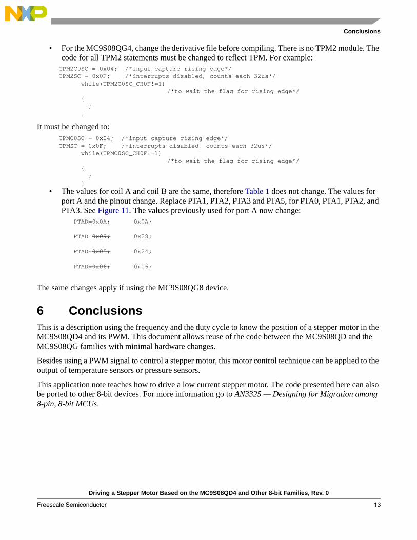
• For the MC9S08QG4, change the derivative file before compiling. There is no TPM2 module. The code for all TPM2 statements must be changed to reflect TPM. For example:
TPM2C0SC = 0x04; /*input capture rising edge*/ TPM2SC = 0x0F; /*interrupts disabled, counts each 32us*/ while(TPM2C0SC_CH0F!=1) /*to wait the flag for rising edge*/ { ; }
It must be changed to: TPMC0SC = 0x04; /*input capture rising edge*/ TPMSC = 0x0F; /*interrupts disabled, counts each 32us*/ while(TPMC0SC_CH0F!=1) /*to wait the flag for rising edge*/ { ; }
• The values for coil A and coil B are the same, therefore Table 1 does not change. The values for port A and the pinout change. Replace PTA1, PTA2, PTA3 and PTA5, for PTA0, PTA1, PTA2, and PTA3. See Figure 11. The values previously used for port A now change:
PTAD=0x0A; 0x0A;
PTAD=0x09; 0x28;
PTAD=0x05; 0x24;
PTAD=0x06; 0x06;
The same changes apply if using the MC9S08QG8 device.
6 ConclusionsThis is a description using the frequency and the duty cycle to know the position of a stepper motor in the MC9S08QD4 and its PWM. This document allows reuse of the code between the MC9S08QD and the MC9S08QG families with minimal hardware changes.
Besides using a PWM signal to control a stepper motor, this motor control technique can be applied to the output of temperature sensors or pressure sensors.
This application note teaches how to drive a low current stepper motor. The code presented here can also be ported to other 8-bit devices. For more information go to AN3325 — Designing for Migration among 8-pin, 8-bit MCUs.
Driving a Stepper Motor Based on the MC9S08QD4 and Other 8-bit Families, Rev. 0
Freescale Semiconductor 13

Document Number: AN3602Rev. 04/2008
How to Reach Us:
Home Page:www.freescale.com
Web Support:http://www.freescale.com/support
USA/Europe or Locations Not Listed:Freescale Semiconductor, Inc.Technical Information Center, EL5162100 East Elliot RoadTempe, Arizona 85284+1-800-521-6274 or +1-480-768-2130www.freescale.com/support
Europe, Middle East, and Africa:Freescale Halbleiter Deutschland GmbHTechnical Information CenterSchatzbogen 781829 Muenchen, Germany+44 1296 380 456 (English)+46 8 52200080 (English)+49 89 92103 559 (German)+33 1 69 35 48 48 (French)www.freescale.com/support
Japan:Freescale Semiconductor Japan Ltd.HeadquartersARCO Tower 15F1-8-1, Shimo-Meguro, Meguro-ku,Tokyo 153-0064Japan0120 191014 or +81 3 5437 [email protected]
Asia/Pacific:Freescale Semiconductor Hong Kong Ltd.Technical Information Center2 Dai King StreetTai Po Industrial EstateTai Po, N.T., Hong Kong+800 2666 [email protected]
For Literature Requests Only:Freescale Semiconductor Literature Distribution CenterP.O. Box 5405Denver, Colorado 802171-800-441-2447 or 303-675-2140Fax: [email protected]
Information in this document is provided solely to enable system and software implementers to use Freescale Semiconductor products. There are no express or implied copyright licenses granted hereunder to design or fabricate any integrated circuits or integrated circuits based on the information in this document.
Freescale Semiconductor reserves the right to make changes without further notice to any products herein. Freescale Semiconductor makes no warranty, representation or guarantee regarding the suitability of its products for any particular purpose, nor does Freescale Semiconductor assume any liability arising out of the application or use of any product or circuit, and specifically disclaims any and all liability, including without limitation consequential or incidental damages. “Typical” parameters that may be provided in Freescale Semiconductor data sheets and/or specifications can and do vary in different applications and actual performance may vary over time. All operating parameters, including “Typicals”, must be validated for each customer application by customer’s technical experts. Freescale Semiconductor does not convey any license under its patent rights nor the rights of others. Freescale Semiconductor products are not designed, intended, or authorized for use as components in systems intended for surgical implant into the body, or other applications intended to support or sustain life, or for any other application in which the failure of the Freescale Semiconductor product could create a situation where personal injury or death may occur. Should Buyer purchase or use Freescale Semiconductor products for any such unintended or unauthorized application, Buyer shall indemnify and hold Freescale Semiconductor and its officers, employees, subsidiaries, affiliates, and distributors harmless against all claims, costs, damages, and expenses, and reasonable attorney fees arising out of, directly or indirectly, any claim of personal injury or death associated with such unintended or unauthorized use, even if such claim alleges that Freescale Semiconductor was negligent regarding the design or manufacture of the part.
RoHS-compliant and/or Pb-free versions of Freescale products have the functionality and electrical characteristics as their non-RoHS-compliant and/or non-Pb-free counterparts. For further information, see http://www.freescale.com or contact your Freescale sales representative.
For information on Freescale’s Environmental Products program, go to http://www.freescale.com/epp.
Freescale™ and the Freescale logo are trademarks of Freescale Semiconductor, Inc. All other product or service names are the property of their respective owners.© Freescale Semiconductor, Inc. 4/2008. All rights reserved.