driver manual (supplement to the fieldserver instruction ... · fs-8700-86 carrier dataport page 3...
TRANSCRIPT
A Sierra Monitor Company
APPLICABILITY & EFFECTIVITY
Effective for all systems manufactured after August 2008
Driver Manual
(Supplement to the FieldServer Instruction Manual)
FS-8700-86 Carrier DataPort
Driver Version: 1.03 Document Revision: 11

FS-8700-86 Carrier DataPort Table of Contents
FieldServer Technologies 1991 Tarob Court Milpitas, California 95035 USA Web: www.fieldserver.com Tel: (408) 262 2299 Fax: (408) 262 2269 Toll Free: (888) 509 1970 email: [email protected]
TABLE OF CONTENTS
1. CARRIER DATAPORT DESCRIPTION ........................................................................................... 3 2. DRIVER SCOPE OF SUPPLY.......................................................................................................... 3
2.1. Supplied by FieldServer Technologies for this driver ................................................................. 3
3. HARDWARE CONNECTIONS ......................................................................................................... 4 4. CONFIGURING THE FIELDSERVER AS A CARRIER DATAPORT CLIENT................................ 5
4.1. Data Arrays ................................................................................................................................. 5 4.2. Client Side Connections.............................................................................................................. 6 4.3. Client Side Node Descriptors...................................................................................................... 7 4.4. Client Side Map Descriptors ....................................................................................................... 8 4.4.1. FieldServer Related Map Descriptor Parameters ................................................................... 8 4.4.2. Driver Related Map Descriptor Parameters ............................................................................ 8 4.4.3. Timing Parameters .................................................................................................................. 8 4.4.4. Map Descriptor Example 1 – Read ......................................................................................... 9
5. CONFIGURING THE FIELDSERVER AS A CARRIER DATAPORT SERVER............................ 10 5.1. Data Arrays ............................................................................................................................... 10 5.2. Server Side Connections .......................................................................................................... 11 5.3. Server Side Node Descriptors .................................................................................................. 11 5.4. Server Side Map Descriptors .................................................................................................... 12 5.4.1. FieldServer Specific Map Descriptor Parameters ................................................................. 12 5.4.2. Driver Specific Map Descriptor Parameters .......................................................................... 12 5.4.3. Timing Parameters ................................................................................................................ 13 5.4.4. Map Descriptor Example. ...................................................................................................... 14
APPENDIX A. ADVANCED TOPICS.................................................................................................... 15 Appendix A.1. Field Status & Field Engineering Units....................................................................... 15 Appendix A.2. Field / Variable Names............................................................................................... 16 Appendix A.3. Map Descriptor Length Explained .............................................................................. 19 Appendix A.4. How the Client stores the states/values of the Table Variables................................. 19 Appendix A.4.1. Discrete States........................................................................................................ 19 Appendix A.4.2. Time Values ............................................................................................................ 20 Appendix A.4.3. Numeric Values....................................................................................................... 21 Appendix A.4.4. Occupancy Strings / Values.................................................................................... 21
APPENDIX B. TROUBLE SHOOTING/CONNECTIONS - TIPS AND HINTS..................................... 22 Appendix B.1. Connection problems. ................................................................................................ 22 Appendix B.2. Timeouts..................................................................................................................... 22 Appendix B.3. Determining Storage Locations.................................................................................. 22 Appendix B.4. How to build a script file that tests a customer log. .................................................... 23
APPENDIX C. DRIVER NOTES ........................................................................................................... 26 Appendix C.1. Driver Limitations and Exclusions .............................................................................. 26
APPENDIX D. DRIVER ERROR MESSAGES ..................................................................................... 27 Appendix D.1. Driver Stats ................................................................................................................ 31
FS-8700-86 Carrier DataPort Page 3 of 32
FieldServer Technologies 1991 Tarob Court Milpitas, California 95035 USA Web: www.fieldserver.com Tel: (408) 262 2299 Fax: (408) 262 2269 Toll Free: (888) 509 1970 email: [email protected]
1. Carrier DataPort Description
The Carrier DataPort driver allows the FieldServer to transfer data to and from devices over either RS-232 or RS-485 using Carrier DataPort protocol. The FieldServer can emulate either a Server or Client. The DataPort device provides a gateway to CCN devices. This driver polls the DataPort device which in turn reads data from the CCN devices. Up to 15 system elements may be connected to a DataPort Device. Carrier limits the number of CCN devices that can polled from a DataPort Device and also limits the data that can be transferred between some CCN devices and the DataPort device. For information on these limitations please consult the Carrier Corporation. The driver is an active Client driver. This means that it initiates read polls with the DataPort device which is expected to provide responses. Server functionality is provided by the driver too. The driver is configured to allow a single Data Table (usually the Display Table) to be read from the CCN devices via the DataPort device. As the table typically contains more than one data element, the retrieved data is stored in a number of consecutive Data Array locations in the FieldServer. The driver can provide descriptions for each of the table values retrieved. The driver has no advanced knowledge of the CCN devices and their Data Tables. This means that the driver handles each table in a generic way, without regard for the particular variables that constitute the tables. The most important consequence of this is that the variable values are stored in the order in which they appear in the response from the DataPort device. It is not possible to map particular variable values to particular locations in the FieldServer Data Arrays.
2. Driver Scope of Supply
2.1. Supplied by FieldServer Technologies for this driver
FieldServer Technologies PART # DESCRIPTION
FS-8917-02 RJ45 to DB9F connector adapter
FS-8917-17 RJ45 to DB25M connection adapter
SPA59132 RS-485 connection adapter
FS-8700-86 Driver Manual.
FS-8700-86 Carrier DataPort Page 4 of 32
FieldServer Technologies 1991 Tarob Court Milpitas, California 95035 USA Web: www.fieldserver.com Tel: (408) 262 2299 Fax: (408) 262 2269 Toll Free: (888) 509 1970 email: [email protected]
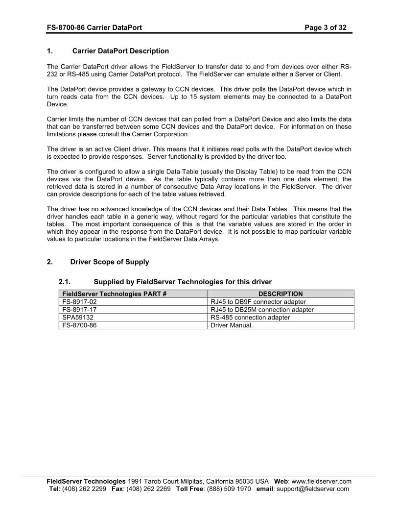
3. Hardware Connections
The FieldServer is connected to the Carrier DataPort device as shown below. Configure the DataPort Device according to manufacturer’s instructions. This driver requires that the DataPort device’s DTPCONFIG table has been configured prior to connection with a FieldServer. In addition, consult the manufacturer’s information on connecting Carrier Device’s to CCN network. Note: Typical connections are 9600,N,8,1.
FS-8700-86 Carrier DataPort Page 5 of 32
FieldServer Technologies 1991 Tarob Court Milpitas, California 95035 USA Web: www.fieldserver.com Tel: (408) 262 2299 Fax: (408) 262 2269 Toll Free: (888) 509 1970 email: [email protected]
4. Configuring the FieldServer as a Carrier DataPort Client
It is not possible to complete a configuration for communication with a DataPort device until you are familiar with the data available from the devices connected to the DataPort. The DataPort device does not provide a method for discovering the data tables and variables that are available in all the Carrier devices.
Configuring the DataPort driver as a Client is easy; however, you will not be able to complete the server side configuration until you have a list of the variables and the order in which the DataPort device will report them. The driver is capable of helping you determine this information but cannot auto-complete the configuration. This method is discussed in Appendix A.
For a detailed discussion on FieldServer configuration, please refer to the FieldServer Configuration Manual. The information that follows describes how to expand upon the factory defaults provided in the configuration files included with the FieldServer (See “.csv” sample files provided with the FieldServer).
This section documents and describes the parameters necessary for configuring the FieldServer to communicate with a Carrier DataPort Server.
The configuration file tells the FieldServer about its interfaces, and the routing of data required. In order to enable the FieldServer for Carrier DataPort communications, the driver independent FieldServer buffers need to be declared in the “Data Arrays” section, the destination device addresses need to be declared in the “Client Side Nodes” section, and the data required from the servers needs to be mapped in the “Client Side Map Descriptors” section. Details on how to do this can be found below.
Note that in the tables, * indicates an optional parameter, with the bold legal value being the default.
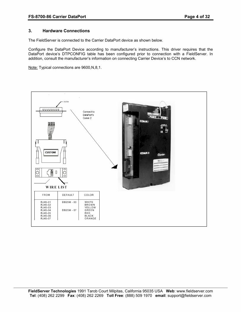
4.1. Data Arrays
Section Title
Data_Arrays
Column Title Function Legal Values
Data_Array_Name Provide name for Data Array Up to 15 alphanumeric characters
Data_Format Provide data format. Each Data Array can only take on one format.
FLOAT, BIT, UInt16, SInt16, Packed_Bit, Byte, Packed_Byte, Swapped_Byte
Data_Array_Length Number of Data Objects. Must be larger than the data storage area required for the data being placed in this array.
1-10,000
Example
// Data Arrays // Data_Arrays Data_Array_Name, Data_Format, Data_Array_Length DA_AI_01, UInt16, 200 DA_AO_01, UInt16, 200 DA_DI_01, Bit, 200 DA_DO_01, Bit, 200
FS-8700-86 Carrier DataPort Page 6 of 32
FieldServer Technologies 1991 Tarob Court Milpitas, California 95035 USA Web: www.fieldserver.com Tel: (408) 262 2299 Fax: (408) 262 2269 Toll Free: (888) 509 1970 email: [email protected]
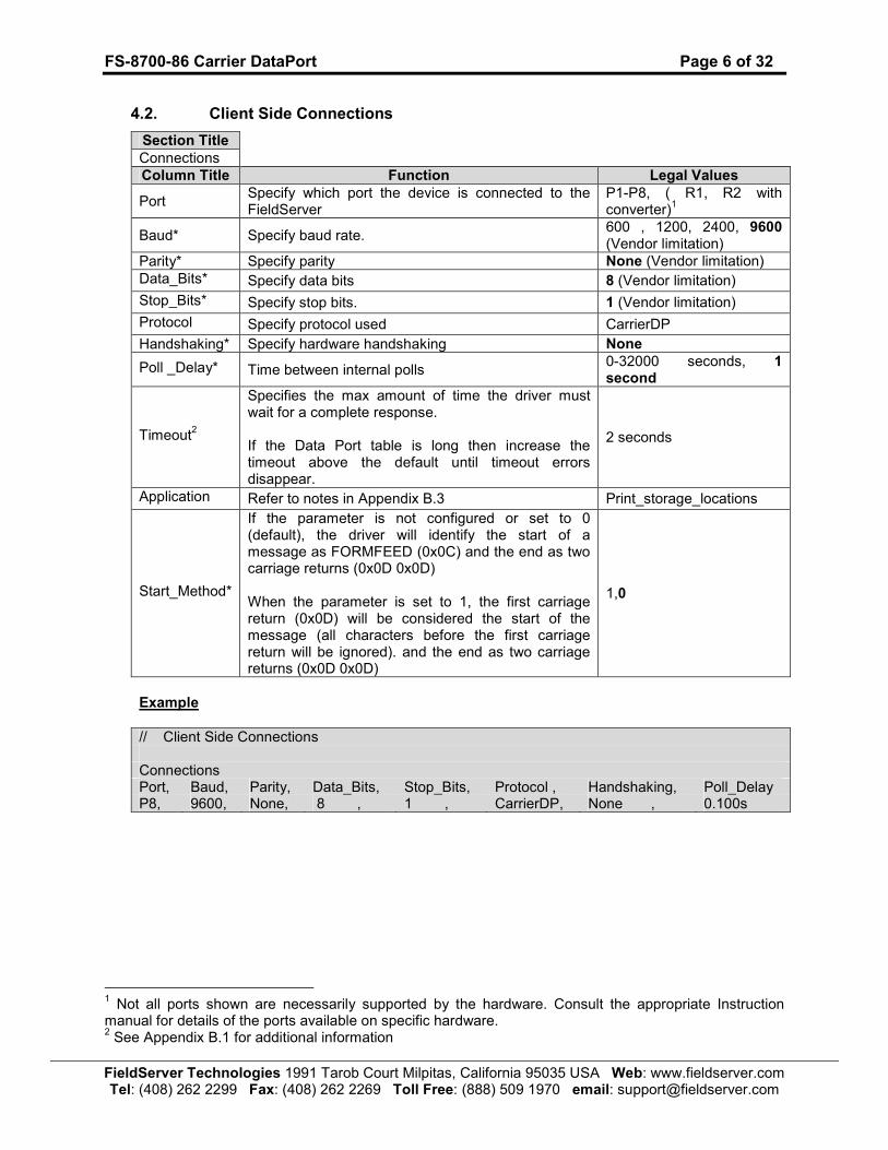
4.2. Client Side Connections
Section Title
Connections
Column Title Function Legal Values
Port Specify which port the device is connected to the FieldServer
P1-P8, ( R1, R2 with converter)
1
Baud* Specify baud rate. 600 , 1200, 2400, 9600 (Vendor limitation)
Parity* Specify parity None (Vendor limitation)
Data_Bits* Specify data bits 8 (Vendor limitation)
Stop_Bits* Specify stop bits. 1 (Vendor limitation)
Protocol Specify protocol used CarrierDP
Handshaking* Specify hardware handshaking None
Poll _Delay* Time between internal polls 0-32000 seconds, 1 second
Timeout2
Specifies the max amount of time the driver must wait for a complete response. If the Data Port table is long then increase the timeout above the default until timeout errors disappear.
2 seconds
Application Refer to notes in Appendix B.3 Print_storage_locations
Start_Method*
If the parameter is not configured or set to 0 (default), the driver will identify the start of a message as FORMFEED (0x0C) and the end as two carriage returns (0x0D 0x0D) When the parameter is set to 1, the first carriage return (0x0D) will be considered the start of the message (all characters before the first carriage return will be ignored). and the end as two carriage returns (0x0D 0x0D)
1,0
Example
// Client Side Connections Connections Port, Baud, Parity, Data_Bits, Stop_Bits, Protocol , Handshaking, Poll_Delay P8, 9600, None, 8 , 1 , CarrierDP, None , 0.100s
1 Not all ports shown are necessarily supported by the hardware. Consult the appropriate Instruction manual for details of the ports available on specific hardware. 2 See Appendix B.1 for additional information

FS-8700-86 Carrier DataPort Page 7 of 32
FieldServer Technologies 1991 Tarob Court Milpitas, California 95035 USA Web: www.fieldserver.com Tel: (408) 262 2299 Fax: (408) 262 2269 Toll Free: (888) 509 1970 email: [email protected]
4.3. Client Side Node Descriptors
Section Title
Nodes
Column Title
Function Legal Values
Node_Name Provide name for node Up to 32 alphanumeric characters
Node_ID
These correspond to the ‘devices’ configured in the DTPConfig. Thus the Node_ID is not the address of the final CCN device. The DataPort DTPConfig table maps a device number (1...15) to a bus number (0-239). Use the Node_ID to tell the driver which device to use.
1-15
Protocol Specify protocol used CarrierDP
Port Specify which port the device is connected to the FieldServer P1-P8, R1-R23
Example
// Client Side Nodes
Nodes Node_Name, Node_ID, Protocol , Port FAN1 , 1 , CarrierDP, P8
3 Not all ports shown are necessarily supported by the hardware. Consult the appropriate Instruction manual for details of the ports available on specific hardware.
FS-8700-86 Carrier DataPort Page 8 of 32
FieldServer Technologies 1991 Tarob Court Milpitas, California 95035 USA Web: www.fieldserver.com Tel: (408) 262 2299 Fax: (408) 262 2269 Toll Free: (888) 509 1970 email: [email protected]
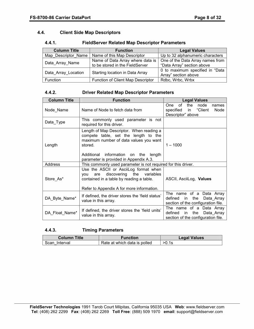
4.4. Client Side Map Descriptors
4.4.1. FieldServer Related Map Descriptor Parameters
Column Title Function Legal Values
Map_Descriptor_Name Name of this Map Descriptor Up to 32 alphanumeric characters
Data_Array_Name Name of Data Array where data is to be stored in the FieldServer
One of the Data Array names from “Data Array” section above
Data_Array_Location Starting location in Data Array 0 to maximum specified in “Data Array” section above
Function Function of Client Map Descriptor Rdbc, Wrbc, Wrbx
4.4.2. Driver Related Map Descriptor Parameters
Column Title Function Legal Values
Node_Name Name of Node to fetch data from One of the node names specified in “Client Node Descriptor” above
Data_Type This commonly used parameter is not required for this driver.
Length
Length of Map Descriptor. When reading a compete table, set the length to the maximum number of data values you want stored. Additional information on the length parameter is provided in Appendix A.3.
1 – 1000
Address This commonly used parameter is not required for this driver.
Store_As*
Use the ASCII or AsciiLog format when you are discovering the variables contained in a table by reading a table. Refer to Appendix A for more information.
ASCII, AsciiLog, Values
DA_Byte_Name* If defined, the driver stores the ‘field status’ value in this array.
The name of a Data Array defined in the Data_Array section of the configuration file.
DA_Float_Name* If defined, the driver stores the ‘field units’ value in this array.
The name of a Data Array defined in the Data_Array section of the configuration file.
4.4.3. Timing Parameters
Column Title Function Legal Values
Scan_Interval Rate at which data is polled >0.1s
FS-8700-86 Carrier DataPort
Page 9 of 32
FieldServer Technologies 1991 Tarob Court M
ilpitas, California 95035 U
SA W
eb: www.fieldserver.com
Tel: (408) 262 2299 Fax: (408) 262 2269 Toll Free: (888) 509 1970 email: support@
fieldserver.com
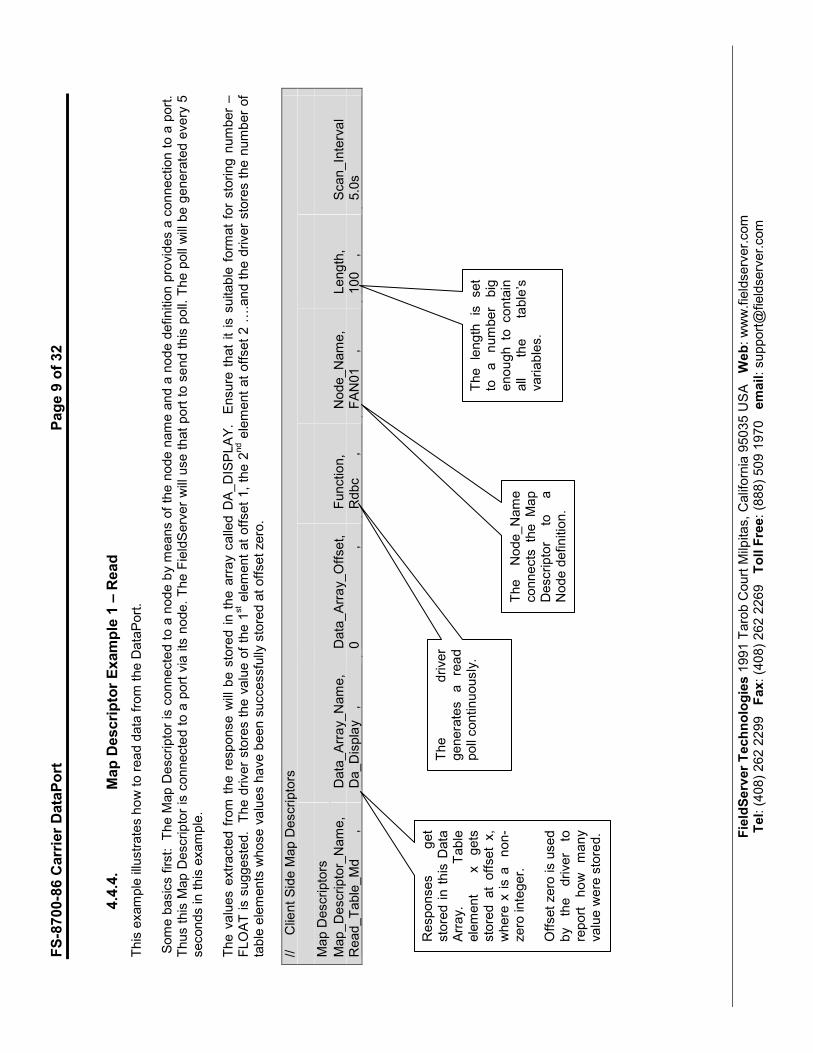
4.4.4.
Map Descriptor Example 1 – Read
This example illustrates how to read data from the DataPort.
Some basics first: The M
ap D
escriptor is connected to a node by m
eans of the node name and a node definition provides a connection to a port.
Thus this M
ap D
escriptor is connected to a port via its node. The FieldServer will use that port to send this poll. The poll will be generated every 5
seconds in this example.
The values extracted from the response w
ill be stored in the array called D
A_DISPLAY. E
nsure that it is suitable form
at for storing number –
FLOAT is suggested. The driver stores the value of the 1
st element at offset 1, the 2
nd element at offset 2 …
.and the driver stores the number of
table elements whose values have been successfully stored at offset zero.
// Client Side M
ap D
escriptors
Map D
escriptors
Map_Descriptor_Name,
Data_Array_Name,
Data_Array_Offset,
Function,
Node_Name,
Length,
Scan_Interval
Read_Table_Md ,
Da_Display ,
0 ,
Rdbc ,
FAN01 ,
100 ,
5.0s
Responses
get
stored in this D
ata
Array.
Table
element
x gets
stored at offset x,
where x is a non-
zero integer.
Offset zero is used
by the driver
to
report how many
value w
ere stored.
The
driver
generates a read
poll continuously.
The
Node_Name
connects the Map
Descriptor
to
a
Node definition.
The length is set
to a number
big
enough to contain
all
the
table’s
variables.
FS-8700-86 Carrier DataPort Page 10 of 32
FieldServer Technologies 1991 Tarob Court Milpitas, California 95035 USA Web: www.fieldserver.com Tel: (408) 262 2299 Fax: (408) 262 2269 Toll Free: (888) 509 1970 email: [email protected]
5. Configuring the FieldServer as a Carrier DataPort Server
For a detailed discussion on FieldServer configuration, please refer to the FieldServer Configuration Manual. The information that follows describes how to expand upon the factory defaults provided in the configuration files included with the FieldServer (See “.csv” sample files provided with the FieldServer). This section documents and describes the parameters necessary for configuring the FieldServer to communicate with a Carrier DataPort Client. The FieldServer can be configured to emulate a Carrier DataPort Device. The user is able to define a variable quantity of variables. The FieldServer may be polled and will respond like a DataPort device. The configuration file tells the FieldServer about its interfaces, and the routing of data required. In order to enable the FieldServer for Carrier DataPort communications, the driver independent FieldServer buffers need to be declared in the “Data Arrays” section, the FieldServer virtual node(s) needs to be declared in the “Server Side Nodes” section, and the data to be provided to the Clients needs to be mapped in the “Server Side Map Descriptors” section. Details on how to do this can be found below.
Note that in the tables, * indicates an optional parameter, with the bold legal value being the default.
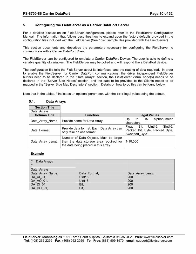
5.1. Data Arrays
Section Title
Data_Arrays
Column Title Function Legal Values
Data_Array_Name Provide name for Data Array Up to 15 alphanumeric characters
Data_Format Provide data format. Each Data Array can only take on one format.
Float, Bit, Uint16, Sint16, Packed_Bit, Byte, Packed_Byte, Swapped_Byte
Data_Array_Length Number of Data Objects. Must be larger than the data storage area required for the data being placed in this array.
1-10,000
Example
// Data Arrays // Data_Arrays Data_Array_Name, Data_Format, Data_Array_Length DA_AI_01, Uint16, 200 DA_AO_01, Uint16, 200 DA_DI_01, Bit, 200 DA_DO_01, Bit, 200

FS-8700-86 Carrier DataPort Page 11 of 32
FieldServer Technologies 1991 Tarob Court Milpitas, California 95035 USA Web: www.fieldserver.com Tel: (408) 262 2299 Fax: (408) 262 2269 Toll Free: (888) 509 1970 email: [email protected]
5.2. Server Side Connections
Section Title
Connections
Column Title Function Legal Values
Port Specify which port the device is connected to the FieldServer
P1-P8, ( R1-R2 with converter)4
Baud* Specify baud rate 300, 600 , 1200, 2400, 9600 (Vendor limitation)
Parity* Specify parity None (Vendor limitation)
Data_Bits* Specify data bits 8 (Vendor limitation)
Stop_Bits* Specify stop bits 1 (Vendor limitation)
Protocol Specify protocol used CarrierDP
Handshaking* Specify hardware handshaking None
Example
// Server Side Connections Connections Port, Baud, Parity, Data_Bits, Stop_Bits, Protocol , Handshaking, Poll_Delay P8, 9600, None, 8 , 1 , CarrierDP, None , 0.100s
5.3. Server Side Node Descriptors
Section Title
Nodes
Column Title Function Legal Values
Node_Name Provide name for Node Up to 32 alphanumeric characters
Node_ID
DataPort station address of physical Server Node. These correspond to the ‘devices’ configured in the DTPConfig. Thus the Node_ID is not the address of the final CCN device. The DataPort DTPConfig table maps a device number (1...15) to a bus number (0-239). Use the Node_ID to tell the driver which device to use.
1-15
Protocol Specify protocol used CarrierDP
Example
// Server Side Nodes
Nodes Node_Name, Node_ID, Protocol , Port
5
FAN1 , 1 , CarrierDP, P8
4 Not all ports shown are necessarily supported by the hardware. Consult the appropriate Instruction manual for details of the ports available on specific hardware. 5 It is common to leave server nodes unconnected to a port. This means that the FieldServer can respond with the Node’s data irrespective of which port the request is received on.

FS-8700-86 Carrier DataPort Page 12 of 32
FieldServer Technologies 1991 Tarob Court Milpitas, California 95035 USA Web: www.fieldserver.com Tel: (408) 262 2299 Fax: (408) 262 2269 Toll Free: (888) 509 1970 email: [email protected]
5.4. Server Side Map Descriptors
5.4.1. FieldServer Specific Map Descriptor Parameters
Column Title Function Legal Values
Map_Descriptor_Name Name of this Map Descriptor Up to 32 alphanumeric characters
Data_Array_Name Name of Data Array where data is to be stored in the FieldServer
One of the Data Array names from “Data Array” section above
Data_Array_Location Starting location in Data Array 0 to maximum specified in “Data Array” section above
Function Function of Client Map Descriptor passive
5.4.2. Driver Specific Map Descriptor Parameters
Column Title Function Legal Values
Node_Name Name of Node to fetch data from One of the Node Names specified in “Server Node Descriptor” above
Length6
Length of Map Descriptor. When reading a compete table, set to the maximum number of data values to be stored.
1 – 1000
Table_Name*
The name of the table to be polled, e.g. DISPLAY. This parameter is for display purposes only. The driver does not use the value of this parameter. Some system elements have multiple instances of the same table name. For example, the Terminal System Manager has 64 Temperature Zone configuration tables. The individual tables are named TZONE1 though TZONE64. These tables are accessed by using both the primary & secondary table names. E.g. ‘TZCONF TZONE1’
Only Ascii characters are permitted. When using the table name parameter to specify a primary and secondary table, leave a single space between the two names.
Field_Name This is the field variable pneumonic. An Ascii string which may not contain spaces. Max length 8 characters.
Field_Description Returned when a Client does a read.
An Ascii string which may contain spaces. Max length 24 characters.
Field_Units Returned when a Client does a read. If units have no meaning for the variable set to zero.
A whole number. See Appendix A.1
Field Status*
This parameter is used to set data quality information that is returned when the Client polls for data. If omitted and DA_Byte_Name has not been specified the driver returns zero as the status value.
A whole number. See Appendix A.1 for more information.
6 Additional information on the length parameter is provided in Appendix A.
FS-8700-86 Carrier DataPort Page 13 of 32
FieldServer Technologies 1991 Tarob Court Milpitas, California 95035 USA Web: www.fieldserver.com Tel: (408) 262 2299 Fax: (408) 262 2269 Toll Free: (888) 509 1970 email: [email protected]
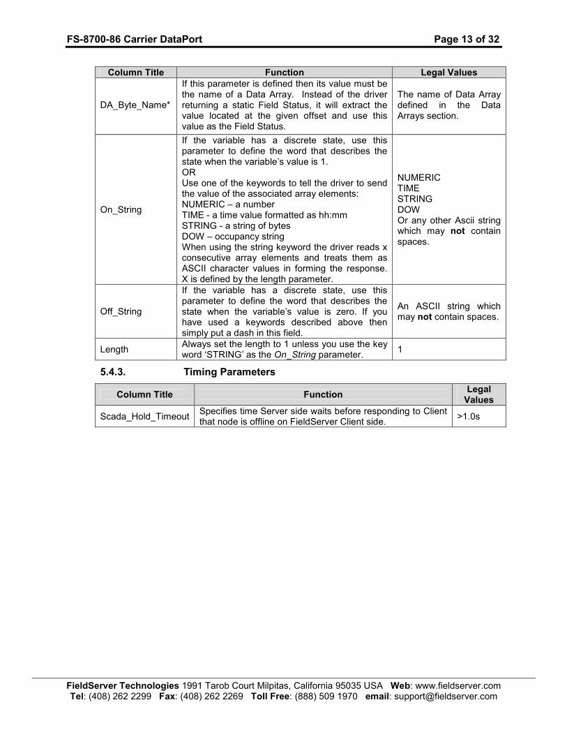
Column Title Function Legal Values
DA_Byte_Name*
If this parameter is defined then its value must be the name of a Data Array. Instead of the driver returning a static Field Status, it will extract the value located at the given offset and use this value as the Field Status.
The name of Data Array defined in the Data Arrays section.
On_String
If the variable has a discrete state, use this parameter to define the word that describes the state when the variable’s value is 1. OR Use one of the keywords to tell the driver to send the value of the associated array elements: NUMERIC – a number TIME - a time value formatted as hh:mm STRING - a string of bytes DOW – occupancy string When using the string keyword the driver reads x consecutive array elements and treats them as ASCII character values in forming the response. X is defined by the length parameter.
NUMERIC TIME STRING DOW Or any other Ascii string which may not contain spaces.
Off_String
If the variable has a discrete state, use this parameter to define the word that describes the state when the variable’s value is zero. If you have used a keywords described above then simply put a dash in this field.
An ASCII string which may not contain spaces.
Length Always set the length to 1 unless you use the key word ‘STRING’ as the On_String parameter.
1
5.4.3. Timing Parameters
Column Title Function Legal Values
Scada_Hold_Timeout Specifies time Server side waits before responding to Client that node is offline on FieldServer Client side.
>1.0s
FS-8700-86 Carrier DataPort
Page 14 of 32
FieldServer Technologies 1991 Tarob Court M
ilpitas, California 95035 U
SA W
eb: www.fieldserver.com
Tel: (408) 262 2299 Fax: (408) 262 2269 Toll Free: (888) 509 1970 email: support@
fieldserver.com
5.4.4.
Map Descriptor Example.
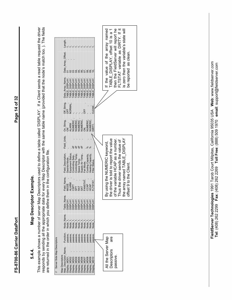
This example shows a number of server Map D
escriptors used to define a table called ‘DISPLAY’. If a C
lient sends a read table request the driver
responds by sending all the appropriate data for every M
ap D
escriptor with the same table name (provided that the node’s m
atch too. ). The fields
are returned in the order in w
hich you define them in the configuration file.
// Server Side M
ap Descriptors
Map Descriptors
Map_Descriptor_Name,
Function,
Node_Name,
Table_Name,
Field_Name,
Field_Description,
Field_Units,
On_String,
Off_String,
Data_Array_Name,
Data_Array_Offset,
Length,
Display_MD01,
passive,
Node_1,
DISPLAY,
MODE ,
Desired M
ode ,
,
ON ,
OFF ,
TABLE_DISPLAY,
01 ,
1,
Display_MD02 ,
passive,
Node_1,
DISPLAY,
ALARM ,
Equipment Status,
,
ALARM ,
NORMAL,
TABLE_DISPLAY,
02 ,
1,
Display_MD03 ,
passive,
Node_1,
DISPLAY,
CSPT ,
Controlling Setp.,
dF ,
NUMERIC ,
-,
TABLE_DISPLAY,
03 ,
1,
Display_MD04 ,
passive,
Node_1,
DISPLAY,
SPT ,
Controlling Temp,
dF ,
NUMERIC,
-,
TABLE_DISPLAY,
04,
1,
Display_MD05 ,
passive,
Node_1,
DISPLAY,
RAT ,
Space Temp,
dF ,
NUMERIC ,
-,
TABLE_DISPLAY,
05,
1,
Display_MD06 ,
passive,
Node_1,
DISPLAY,
SAT ,
Supply Air Temp.,
dF ,
NUMERIC,
-,
TABLE_DISPLAY,
06,
1,
Display_MD07 ,
passive,
Node_1,
DISPLAY,
FANSTAT,
Fan M
ode,
, ON,
OFF ,
TABLE_DISPLAY,
07,
1,
Display_MD08 ,
passive,
Node_1,
DISPLAY,
CCAP ,
Cooling Capacity,
% ,
NUMERIC,
- ,
TABLE_DISPLAY,
08,
1,
Display_MD09 ,
passive,
Node_1,
DISPLAY,
HCAP ,
Heating Capacity,
% ,
NUMERIC,
- ,
TABLE_DISPLAY,
09,
1,
Display_MD10 ,
passive,
Node_1,
DISPLAY,
FLTSTAT,
Filter Status,
, DIRTY,
CLEAN ,
TABLE_DISPLAY,
10,
1,
All the S
erver Map
Descriptors
are
passive.
If the value of the array named
TABLE_DISPLAY, offset 10 is a 1
then the F
ieldServer will report he
FLTSTAT variable as DIR
TY. If it
is zero then the variable’s state w
ill
be reported as clean.
By using the NUMERIC keyword,
the driver is told to report the value
of the variable HCAP as a number.
Thus the driver sends the value of
the array named TABLE_DISPLAY
offset 9 to the C
lient.

FS-8700-86 Carrier DataPort Page 15 of 32
FieldServer Technologies 1991 Tarob Court Milpitas, California 95035 USA Web: www.fieldserver.com Tel: (408) 262 2299 Fax: (408) 262 2269 Toll Free: (888) 509 1970 email: [email protected]
Appendix A. Advanced Topics
Appendix A.1. Field Status & Field Engineering Units
The following tables duplicate information available from Carrier Corporation. We provide it for reference purposes. It is best to ask the vendor for current data.
Value Engineering Units Value Engineering Units Value Engineering Units
000 no units 051 feet per minute 260 Pascal
001 degrees F 052 thousands of cubic feet per minute
262 delta degrees C
002 degrees F 053 thousands of cubic feet per hour
263 degrees C
003 percent 054 tons 264 delta degrees C
004 inches of water 055 tons per hour 267 degrees C
005 milliamps 056 revolutions per minute 270 Pascal
006 delta degrees F 057 percent open 272 delta degrees C
007 degrees F 058 hours 273 degrees C
008 delta degrees F 059 gallons 274 delta degrees C
010 Volts 064 on/off input 276 kiloPascals
011 degrees F 065 off/on input 288 liters per minute
013 percent 066 input pulses on 289 liter per hour
014 inches of water 067 input pulses off 290 cubic meters per minute
015 milliamps 068 seconds 291 cubic meters per hour
016 delta degrees F 069 normal/alarm 292 kiloPascals
017 degrees F 070 Hz 293 kilograms per hour
018 delta degrees F 080 minutes 295 kilowatt hours
020 pounds per square inch 081 hours 296 kilowatts
032 gallons per minute 082 revolutions per minute 297 millimeters of water
033 gallons per hour 124 clock 298 millimeters of mercury
034 thousands of gallons per minute
126 ASCII 299 kilowatt hours
035 thousands of gallons per hour
128 no units 300 kilowatts
036 pounds per square inch, gauge
133 milliamp 301 degrees C
037 pounds per hour 137 pounds per square inch 302 percent relative humidity
038 thousands of pounds per hour
138 volts 303 amps
039 BTUs per hour 144 kilowatts 304 volts
040 thousands of BTUs 145 kilowatt hours/pulse 305 cubic meters per minute
041 inches of water 146 pulses 306 cubic meters per hour
042 inches of mercury 192 on/off output 307 meters per second
043 kilowatt hours 193 off/on output 310 tons
044 kilowatts 194 pulsed on output 311 tons per hour
045 degrees F 195 pulsed off output 312 revolutions per hour
046 percent relative humidity 208 steps 313 percent open
047 amps 254 ASCII 314 hours
048 volts 256 no units 315 liters
049 cubic feet per minute 257 degrees C
050 cubic feet per hour 258 degrees C
FS-8700-86 Carrier DataPort Page 16 of 32
FieldServer Technologies 1991 Tarob Court Milpitas, California 95035 USA Web: www.fieldserver.com Tel: (408) 262 2299 Fax: (408) 262 2269 Toll Free: (888) 509 1970 email: [email protected]
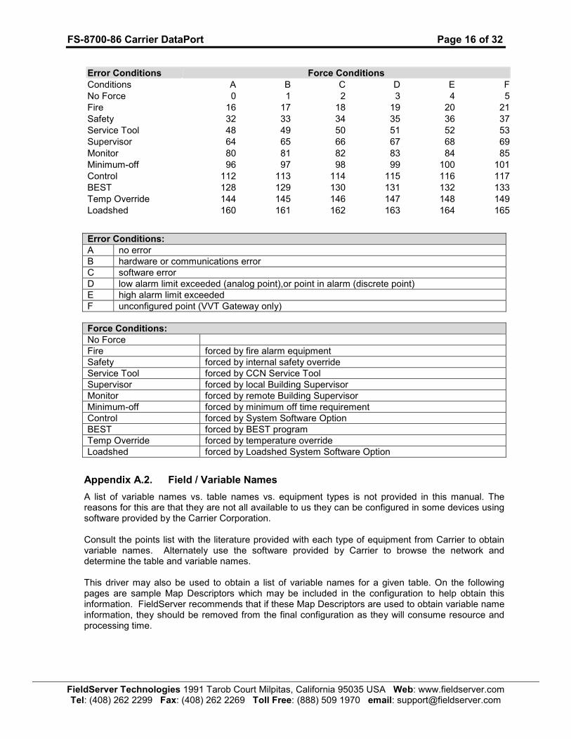
Error Conditions Force Conditions
Conditions A B C D E F
No Force 0 1 2 3 4 5
Fire 16 17 18 19 20 21
Safety 32 33 34 35 36 37
Service Tool 48 49 50 51 52 53
Supervisor 64 65 66 67 68 69
Monitor 80 81 82 83 84 85
Minimum-off 96 97 98 99 100 101
Control 112 113 114 115 116 117
BEST 128 129 130 131 132 133
Temp Override 144 145 146 147 148 149
Loadshed 160 161 162 163 164 165
Error Conditions:
A no error
B hardware or communications error
C software error
D low alarm limit exceeded (analog point),or point in alarm (discrete point)
E high alarm limit exceeded
F unconfigured point (VVT Gateway only)
Force Conditions:
No Force
Fire forced by fire alarm equipment
Safety forced by internal safety override
Service Tool forced by CCN Service Tool
Supervisor forced by local Building Supervisor
Monitor forced by remote Building Supervisor
Minimum-off forced by minimum off time requirement
Control forced by System Software Option
BEST forced by BEST program
Temp Override forced by temperature override
Loadshed forced by Loadshed System Software Option
Appendix A.2. Field / Variable Names
A list of variable names vs. table names vs. equipment types is not provided in this manual. The reasons for this are that they are not all available to us they can be configured in some devices using software provided by the Carrier Corporation. Consult the points list with the literature provided with each type of equipment from Carrier to obtain variable names. Alternately use the software provided by Carrier to browse the network and determine the table and variable names. This driver may also be used to obtain a list of variable names for a given table. On the following pages are sample Map Descriptors which may be included in the configuration to help obtain this information. FieldServer recommends that if these Map Descriptors are used to obtain variable name information, they should be removed from the final configuration as they will consume resource and processing time.
FS-8700-86 Carrier DataPort
Page 17 of 32
FieldServer Technologies 1991 Tarob Court M
ilpitas, California 95035 U
SA W
eb: www.fieldserver.com
Tel: (408) 262 2299 Fax: (408) 262 2269 Toll Free: (888) 509 1970 email: support@
fieldserver.com
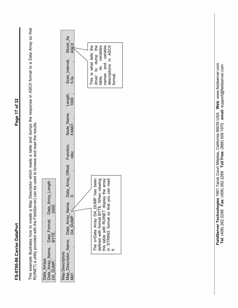
This example illustrates how to create a M
ap D
escriptor which reads a table and dumps the response in A
SCII form
at to a D
ata A
rray so that
RUINET( a utility provided w
ith the FieldServer) can be used to browse and read the results.
Data_Arrays
Data_Array_Name,
Data_Form
at,
Data_Array_Length
DA_DUMP,
BYTE,
2000
Map D
escriptors
Map_Descriptor_Name,
Data_Array_Name,
Data_Array_Offset,
Function,
Node_Name,
Length,
Scan_Interval,
Storet_As
Md1 ,
DA_DUMP ,
0 ,
rdbc ,
FAN01 ,
1000 ,
5.0s ,
ASCII
This is what tells the
driver
to dump the
table,
its
variables
names
and
variable
descriptions in ASCII
form
at.
The s=Data Array DA_DUMP has been
defined w
ith form
at BYTE. When viewing
this table w
ith R
UIN
ET display the array
in ‘STRING’ form
at so that you can read
it.

FS-8700-86 Carrier DataPort
Page 18 of 32
FieldServer Technologies 1991 Tarob Court M
ilpitas, California 95035 U
SA W
eb: www.fieldserver.com
Tel: (408) 262 2299 Fax: (408) 262 2269 Toll Free: (888) 509 1970 email: support@
fieldserver.com
This example illustrates how to m
ake a M
ap D
escriptor which reads a table and dumps the response in ASCII form
at to the error log. The error log
can be dumped to a file on your computer using R
UID
EBUG (a utility supplied w
ith your FieldServer)
Data_Arrays
Data_Array_Name,
Data_Form
at,
Data_Array_Length
DA_DUMP,
BYTE,
2000
Map D
escriptors
Map_Descriptor_Name,
Data_Array_Name,
Data_Array_Offset,
Function,
Node_Name,
Length,
Scan_Interval,
Storet_As
Md1 ,
Da_Dump ,
0 ,
rdbc ,
FAN01 ,
1000 ,
5.0s ,
AsciiLog
The following fragment from the error log is typical of the response to a M
ap D
escriptor like the one above.
T01> ASCII D
ump Requested for MD=<MapDesc1>
T01> Field1 99.0 000 000 D
esc1 1 1
T01> Field2 98.0 000 000 D
esc2222222
T01> Field3 on 000 000 33333 33333 3
T01> Field4 Off 000 000 44444444444444
T01> Field5 Off 000 000 5555 55555555
T01> Field6 Off 000 000 6666666666666
T01> Field7 Off 000 000 7
T01> Field8 Off 000 000 888 888 88888
T01> Field9 Off 000 000 99999999999 3
T01> Fielda DIRTY 000 000 aaaaaaaaaaaaa
T01> Fieldb 0.0 000 000 bbbb
T01> Fieldc Off 000 000 c
T01> Fieldd -1.0 000 000 ddddddddddddd

FS-8700-86 Carrier DataPort Page 19 of 32
FieldServer Technologies 1991 Tarob Court Milpitas, California 95035 USA Web: www.fieldserver.com Tel: (408) 262 2299 Fax: (408) 262 2269 Toll Free: (888) 509 1970 email: [email protected]
Appendix A.3. Map Descriptor Length Explained
The Length parameter is specified as part of the Map Descriptor.
Client Reads: The length means: “The number of table variable’s whose values are to be stored when the response is received.” If you do not know the length of the table in advance, set the length to a larger number (e.g. 100). The driver will process the response; if the table contains more than 100 elements then some data will be discarded. Server: The length parameter is used when the server returns a value that is a string. The length is used to tell the driver how many characters to extract from consecutive array location to form the response string. When the server returns a value that is a number, state or time the length should always be 1.
Appendix A.4. How the Client stores the states/values of the Table Variables.
Appendix A.4.1. Discrete States
When a Carrier DataPort device reports the state of a table variable which has a discrete state, it reports the state as a keyword like on/off. This driver converts the keywords to facilitate reading by other devices. The driver is programmed to recognize the keywords listed below. The user can add keywords by specifying additional information in the configuration file.
State Word Value State Word Value State Word Value
CLEAN 1 ABNORMAL 1 OPEN 1
DIRTY 0 NORMAL 0 CLOSE 0
HEAT 1 LOCAL 0 CLOSED 0
COOL 0 REMOTE 1 ALARM 1
ON 1 LOCAL R 0 OFF 0 RUNNING 1
If the driver doesn’t recognize the state word, it stores the characters of the state word as decimal values based on their ASCII value. the number of characters stored is dependent on the length parameter. For example, say the driver responds, reporting a variable to be a state ‘INCREDIBLE’. If the length parameter of the polling Map Descriptor is 1 then the driver stores the first character of the word incredible; by storing a value of 73 (An uppercase ‘I’ is the seventy third character in the ASCII alphabet.). The driver recognizes discrete state words by checking the 1
st character of the value field. If it is a
non-digit then it is regarded as a state word. The comparison against keywords in the list is done without respect for the case of the letters. Unrecognized Discrete State Words If the driver does not recognize the discrete state word that has been used it will report the following error - CarrDP:#24 Err. MD=<MapDesc1> discrete state word not recognized. The unrecognized discrete word can be found by extracting 10 characters from the line starting at the 10th character. Once the 10 characters have been extracted they are left and right trimmed to remove leading and trailing spaces.
FS-8700-86 Carrier DataPort Page 20 of 32
FieldServer Technologies 1991 Tarob Court Milpitas, California 95035 USA Web: www.fieldserver.com Tel: (408) 262 2299 Fax: (408) 262 2269 Toll Free: (888) 509 1970 email: [email protected]
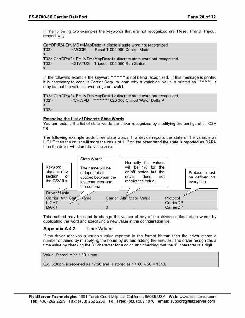
In the following two examples the keywords that are not recognized are 'Reset T' and 'Tripout' respectively CarrDP:#24 Err. MD=<MapDesc1> discrete state word not recognized. T02> <MODE Reset T 000 000 Control Mode > T02> CarrDP:#24 Err. MD=<MapDesc1> discrete state word not recognized. T02> <STATUS Tripout 000 000 Run Status > In the following example the keyword '********' is not being recognized. If this message is printed it is necessary to consult Carrier Corp. to learn why a variables’ value is printed as '********'. It may be that the value is over range or invalid. T02> CarrDP:#24 Err. MD=<MapDesc1> discrete state word not recognized. T02> <CHWPD ********** 020 000 Chilled Water Delta P > T02> Extending the List of Discrete State Words You can extend the list of state words the driver recognizes by modifying the configuration CSV file. The following example adds three state words. If a device reports the state of the variable as LIGHT then the driver will store the value of 1, if on the other hand the state is reported as DARK then the driver will store the value zero.
Driver_Table Carrier_Attr_State_Name, Carrier_Attr_State_Value, Protocol LIGHT , 1 , CarrierDP DARK , 0 , CarrierDP
This method may be used to change the values of any of the driver’s default state words by duplicating the word and specifying a new value in the configuration file.
Appendix A.4.2. Time Values
If the driver receives a variable value reported in the format hh:mm then the driver stores a number obtained by multiplying the hours by 60 and adding the minutes. The driver recognizes a time value by checking the 3
rd character for a colon and checking that the 1
st character is a digit.
Value_Stored = hh * 60 + mm E.g. 5:30pm is reported as 17:20 and is stored as 17*60 + 20 = 1040.
Protocol must be defined on every line.
Keyword starts a new section of the CSV file.
State Words The name will be stripped of all spaces between the last character and the comma.
Normally the values will be 1/0 for the on/off states but the driver does not restrict the value.
FS-8700-86 Carrier DataPort Page 21 of 32
FieldServer Technologies 1991 Tarob Court Milpitas, California 95035 USA Web: www.fieldserver.com Tel: (408) 262 2299 Fax: (408) 262 2269 Toll Free: (888) 509 1970 email: [email protected]
Appendix A.4.3. Numeric Values
The driver recognizes numeric values by checking the first character of the value field. If it is a digit then the field is treated as a number.
Appendix A.4.4. Occupancy Strings / Values
If the value returned for a variable is 8 characters long and each of the characters is a one or a zero then the driver regards this as an occupancy string an converts it to a binary coded decimal value and then stores this value.
E.g.: 00101010 = 42 decimal
FS-8700-86 Carrier DataPort Page 22 of 32
FieldServer Technologies 1991 Tarob Court Milpitas, California 95035 USA Web: www.fieldserver.com Tel: (408) 262 2299 Fax: (408) 262 2269 Toll Free: (888) 509 1970 email: [email protected]
Appendix B. Trouble Shooting/Connections - Tips and Hints
Appendix B.1. Connection problems.
Confirm that the device you are trying to attach to the FieldServer is in fact a DataPort device and not a DataLink device which looks very similar but connects differently. A DataLink device will require the DataLink driver – FieldServer part # FS-8700-82. Please contact FieldServer to request an exchange of driver.
Appendix B.2. Timeouts
Some Data Port tables are long and result in messages of up to 6.5 kB being sent from the data port to the FieldServer. The default timeout is insufficient in such cases. In resolving one customer’s connection problems a timeout of 4 s on a table of 134 entries was found to produce good results. Please read the notes provided with Error message #25 in section Appendix D of this manual.
Appendix B.3. Determining Storage Locations
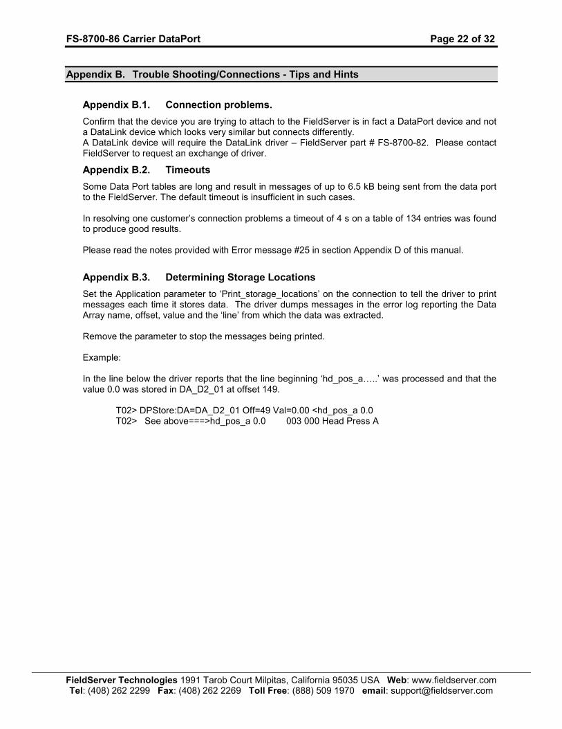
Set the Application parameter to ‘Print_storage_locations’ on the connection to tell the driver to print messages each time it stores data. The driver dumps messages in the error log reporting the Data Array name, offset, value and the ‘line’ from which the data was extracted. Remove the parameter to stop the messages being printed. Example: In the line below the driver reports that the line beginning ‘hd_pos_a…..’ was processed and that the value 0.0 was stored in DA_D2_01 at offset 149.
T02> DPStore:DA=DA_D2_01 Off=49 Val=0.00 <hd_pos_a 0.0 T02> See above===>hd_pos_a 0.0 003 000 Head Press A
FS-8700-86 Carrier DataPort Page 23 of 32
FieldServer Technologies 1991 Tarob Court Milpitas, California 95035 USA Web: www.fieldserver.com Tel: (408) 262 2299 Fax: (408) 262 2269 Toll Free: (888) 509 1970 email: [email protected]
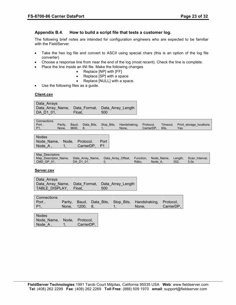
Appendix B.4. How to build a script file that tests a customer log.
The following brief notes are intended for configuration engineers who are expected to be familiar with the FieldServer.
• Take the hex log file and convert to ASCII using special chars (this is an option of the log file converter)
• Choose a response line from near the end of the log (most recent). Check the line is complete.
• Place the line inside an INI file. Make the following changes
• Replace [NP] with [FF]
• Replace [SP] with a space
• Replace [NULL] with a space.
• Use the following files as a guide.
Client.csv
Data_Arrays
Data_Array_Name, Data_Format, Data_Array_Length DA_D1_01, Float, 500
Connections Port , Parity, Baud, Data_Bits, Stop_Bits, Handshaking, Protocol, Timeout, Print_storage_locations P1, None, 9600, 8, 1, None, CarrierDP, 60s, Yes
Nodes
Node_Name, Node, Protocol, Port Node_A , 1, CarrierDP, P1
Map_Descriptors Map_Descriptor_Name, Data_Array_Name, Data_Array_Offset, Function, Node_Name, Length, Scan_Interval, CMD_GP_01, DA_D1_01, 0, Rdbc, Node_A, 202, 5.0s
Server.csv
Data_Arrays
Data_Array_Name, Data_Format, Data_Array_Length TABLE_DISPLAY, Float, 500
Connections
Port , Parity, Baud, Data_Bits, Stop_Bits, Handshaking, Protocol, P1, None, 1200, 8, 1, None, CarrierDP,
Nodes
Node_Name, Node, Protocol, Node_A , 1, CarrierDP,
FS-8700-86 Carrier DataPort
Page 24 of 32
FieldServer Technologies 1991 Tarob Court M
ilpitas, California 95035 U
SA W
eb: www.fieldserver.com
Tel: (408) 262 2299 Fax: (408) 262 2269 Toll Free: (888) 509 1970 email: support@
fieldserver.com
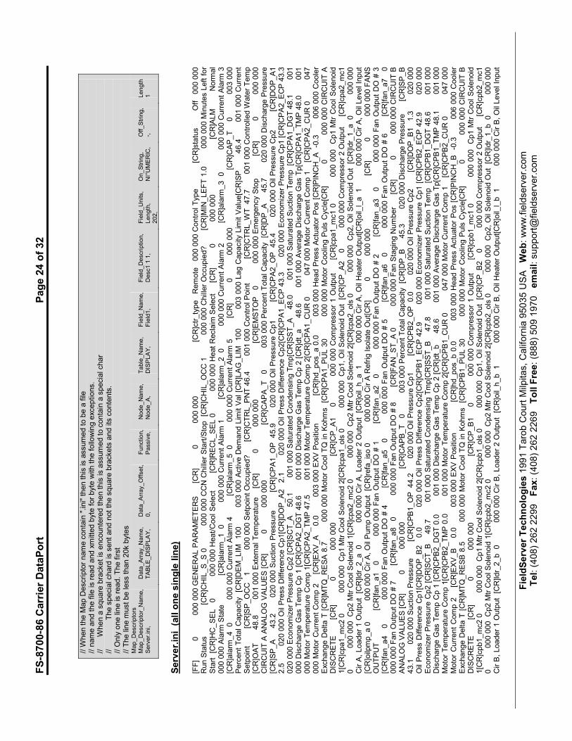
// W
hen the M
ap Descriptor name contain ".ini" then this is assumed to be a file
// name and the file is read and xmitted byte for byte with the following exceptions.
// When a square bracket is encountered then this is assumed to contain a special char
// The special chard is sent and not the square brackets and its contents.
// O
nly one line is read. The first
// The line m
ust be less than 20k bytes
Map_Descriptors
Map_Descriptor_Name,
Data_Array_Name,
Data_Array_Offset,
Function,
Node_Name,
Table_Name,
Field_Name,
Field_Description,
Field_Units,
On_String,
Off_String,
Length
Server.ini,
TABLE_DISPLAY,
0,
Passive,
Node_A,
DISPLAY,
Field1,
Desc1 1 1,
Length,
NI°UMERIC,
-,
1
202,
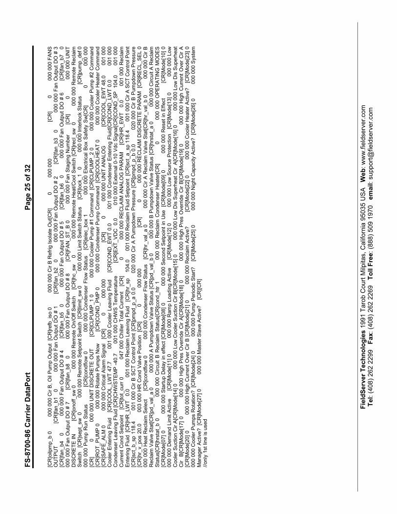
Server.ini (all one single line)
[FF] 0 000 000 G
ENERAL PARAMETERS [CR] 0 000 000 [CR]ctr_type Remote 000 000 Control Type [CR]status Off 000 000
Run Status [CR]CHIL_S_S 0 000 000 C
CN C
hiller Start/Stop [CR]CHIL_OCC 1 000 000 C
hiller Occupied? [CR]M
IN_LEFT 1.0 000 000 M
inutes Left for
Start [CR]HC_SEL 0 000 000 H
eat/Cool Select [CR]RECL_SEL 0 000 000 H
eat Reclaim
Select [CR] 0 000 000 [CR]ALM Norm
al
000 000 Alarm
State [CR]alarm
_1 0 000 000 C
urrent Alarm
1 [CR]alarm
_2 0 000 000 C
urrent Alarm
2 [CR]alarm
_3 0 000 000 C
urrent Alarm
3
[CR]alarm
_4 0 000 000 C
urrent Alarm
4 [CR]alarm
_5 0 000 000 C
urrent Alarm
5 [CR] 0 000 000 [CR]CAP_T 0 003 000
Percent Total Capacity [CR]DEM_LIM
100 003 000 Active D
emand Lim
it Val [CR]LAG_LIM
100 003 000 Lag C
apacity Lim
it Value[CR]SP 46.4 001 000 C
urrent
Setpoint [CR]SP_OCC 1 000 000 Setpoint Occupied? [CR]CTRL_PNT 46.4 001 000 C
ontrol Point [CR]CTRL_WT 47.7 001 000 C
ontrolled W
ater Temp
[CR]O
AT 48.8 001 000 External Temperature [CR] 0 000 000 [CR]EMSTOP 0 000 000 Emergency Stop [CR] 0 000 000
CIRCUIT A ANALOG VALUES [CR] 0 000 000 [CR]CAPA_T 0 003 000 Percent Total Capacity [CR]DP_A 45.7 020 000 D
ischarge Pressure
[CR]SP_A 43.2 020 000 Suction Pressure [CR]CPA1_OP 45.9 020 000 O
il Pressure C
p1 [CR]CPA2_OP 45.4 020 000 O
il Pressure C
p2 [CR]DOP_A1
2.5 020 000 O
il Press Difference Cp1[CR]DOP_A2 2.1 020 000 O
il Press Difference Cp2[CR]CPA1_ECP 43.3 020 000 Economizer Pressure Cp1 [CR]CPA2_ECP 43.3
020 000 Economizer Pressure Cp2 [CR]SCT_A 50.1 001 000 Saturated Condensing Tmp[CR]SST_A 48.0 001 000 Saturated Suction Temp [CR]CPA1_DGT 48.1 001
000 D
ischarge G
as Temp C
p 1 [CR]CPA2_DGT 48.6 001 000 D
ischarge G
as Temp C
p 2 [CR]dt_a 48.6 001 000 Average D
ischarge G
as Tp[CR]CPA1_TMP 48.0 001
000 M
otor Temperature Comp 1[CR]CPA2_TMP 47.5 001 000 M
otor Temperature Comp 2[CR]CPA1_CUR 0 047 000 M
otor Current Comp 1 [CR]CPA2_CUR 0 047
000 M
otor Current Comp 2 [CR]EXV_A 0.0 003 000 EXV Position [CR]hd_pos_a 0.0 003 000 H
ead Press Actuator Pos [CR]PINCH_A -0.3 006 000 C
ooler
Exchange D
elta T [CR]M
TQ_RESA 8.7 000 000 M
otor Cool TQ in Kohms [CR]CPA1_PUL 30 000 000 M
otor Cooling Puls C
ycle[CR] 0 000 000 C
IRCUIT A
DISCRETE [CR] 0 000 000 [CR]CP_A1 0 000 000 C
ompressor 1 O
utput [CR]cpa1_mc1 0 000 000 Cp1 M
tr C
ool Solenoid
1[CR]cpa1_mc2 0 000 000 Cp1 M
tr Cool Solenoid 2[CR]cpa1_ols 0 000 000 Cp1, Oil Solenoid O
ut [CR]CP_A2 0 000 000 Compressor 2 O
utput [CR]cpa2_mc1
0 000 000 Cp2 M
tr Cool Solenoid 1[CR]cpa2_mc2 0 000 000 Cp2 M
tr Cool Solenoid 2[CR]cpa2_ols 0 000 000 Cp2, Oil Solenoid O
ut [CR]ldr_1_a 0 000 000
Cir A, Loader 1 O
utput [CR]ldr_2_a 0 000 000 C
ir A, Loader 2 O
utput [CR]oil_h_a 1 000 000 C
ir A, Oil Heater Output[CR]oil_l_a 1 000 000 C
ir A, Oil Level Input
[CR]oilpmp_a 0 000 000 Cir A, Oil Pump O
utput [CR]refa_iso 0 000 000 Cir A Refrig Isolate O
ut[CR] 0 000 000 [CR] 0 000 000 FANS
OUTPUT [CR]fan_a1 0 000 000 Fan O
utput DO # 1 [CR]fan_a2 0 000 000 Fan O
utput DO # 2 [CR]fan_a3 0 000 000 Fan O
utput DO # 3
[CR]fan_a4 0 000 000 Fan O
utput DO # 4 [CR]fan_a5 0 000 000 Fan O
utput DO # 5 [CR]fan_a6 0 000 000 Fan O
utput DO # 6 [CR]fan_a7 0
000 000 Fan O
utput DO # 7 [CR]fan_a8 0 000 000 Fan O
utput DO # 8 [CR]FAN_ST_A 0 000 000 Fan Staging Number [CR] 0 000 000 CIRCUIT B
ANALOG VALUES [CR] 0 000 000 [CR]CAPB_T 0 003 000 Percent Total Capacity [CR]DP_B 45.3 020 000 Discharge Pressure [CR]SP_B
43.1 020 000 Suction Pressure [CR]CPB1_OP 44.2 020 000 O
il Pressure Cp1 [CR]CPB2_OP 0.0 020 000 O
il Pressure Cp2 [CR]DOP_B1 1.3 020 000
Oil Press D
ifference C
p1[CR]DOP_B2 0.0 020 000 O
il Press D
ifference C
p2[CR]CPB1_ECP 42.9 020 000 Economizer Pressure C
p1 [CR]CPB2_ECP 42.9 020 000
Economizer Pressure C
p2 [CR]SCT_B 49.7 001 000 Saturated C
ondensing Tmp[CR]SST_B 47.8 001 000 Saturated Suction Temp [CR]CPB1_DGT 48.6 001 000
Discharge G
as Temp C
p 1 [CR]CPB2_DGT 0.0 001 000 D
ischarge G
as Temp C
p 2 [CR]dt_b 48.6 001 000 Average D
ischarge G
as Tp[CR]CPB1_TMP 48.1 001 000
Motor Temperature C
omp 1[CR]CPB2_TMP 0.0 001 000 M
otor Temperature C
omp 2[CR]CPB1_CUR 0 047 000 M
otor Current Comp 1 [CR]CPB2_CUR 0 047 000
Motor Current Comp 2 [CR]EXV_B 0.0 003 000 E
XV P
osition [CR]hd_pos_b 0.0 003 000 H
ead P
ress Actuator Pos [CR]PINCH_B -0.3 006 000 C
ooler
Exchange D
elta T [CR]M
TQ_RESB 8.5 000 000 M
otor Cool TQ in Kohms [CR]CPB1_PUL 30 000 000 M
otor Cooling Puls C
ycle[CR] 0 000 000 C
IRCUIT B
DISCRETE [CR] 0 000 000 [CR]CP_B1 0 000 000 C
ompressor 1 O
utput [CR]cpb1_mc1 0 000 000 Cp1 M
tr C
ool Solenoid
1[CR]cpb1_mc2 0 000 000 Cp1 M
tr Cool Solenoid 2[CR]cpb1_ols 0 000 000 Cp1, Oil Solenoid O
ut [CR]CP_B2 0 000 000 Compressor 2 O
utput [CR]cpb2_mc1
0 000 000 Cp2 M
tr Cool Solenoid 1[CR]cpb2_mc2 0 000 000 Cp2 M
tr Cool Solenoid 2[CR]cpb2_ols 0 000 000 Cp2, Oil Solenoid O
ut [CR]ldr_1_b 0 000 000
Cir B, Loader 1 O
utput [CR]ldr_2_b 0 000 000 C
ir B, Loader 2 O
utput [CR]oil_h_b 1 000 000 C
ir B, Oil Heater Output[CR]oil_l_b 1 000 000 C
ir B, Oil Level Input
FS-8700-86 Carrier DataPort
Page 25 of 32
FieldServer Technologies 1991 Tarob Court M
ilpitas, California 95035 U
SA W
eb: www.fieldserver.com
Tel: (408) 262 2299 Fax: (408) 262 2269 Toll Free: (888) 509 1970 email: support@
fieldserver.com
[CR]oilpmp_b 0 000 000 Cir B, Oil Pump O
utput [CR]refb_iso 0 000 000 Cir B Refrig Isolate O
ut[CR] 0 000 000 [CR] 0 000 000 FANS
OUTPUT [CR]fan_b1 0 000 000 Fan O
utput DO # 1 [CR]fan_b2 0 000 000 Fan O
utput DO # 2 [CR]fan_b3 0 000 000 Fan O
utput DO # 3
[CR]fan_b4 0 000 000 Fan O
utput DO # 4 [CR]fan_b5 0 000 000 Fan O
utput DO # 5 [CR]fan_b6 0 000 000 Fan O
utput DO # 6 [CR]fan_b7 0
000 000 Fan O
utput DO # 7 [CR]fan_b8 0 000 000 Fan O
utput DO # 8 [CR]FAN_ST_B 0 000 000 Fan Staging N
umber [CR] 0 000 000 U
NIT
DISCRETE IN [CR]onoff_sw 0 000 000 R
emote O
n/O
ff Switch [CR]hc_sw 0 000 000 R
emote H
eat/Cool Switch [CR]recl_sw 0 000 000 R
emote R
eclaim
Switch [CR]sept_sw 0 000 000 Remote Setpoint Switch [CR]lim
it_sw 0 000 000 Lim
it Switch Status [CR]lock_1 0 000 000 Interlock Status [CR]pump_def 0
000 000 P
ump R
un S
tatus [CR]condflow 0 000 000 C
ondenser Flow S
tatus [CR]elec_box 1 000 000 E
lectrical Box S
afety S
w[CR] 0 000 000
[CR] 0 000 000 U
NIT D
ISCRETE O
UT [CR]CLPUMP_1 0 000 000 C
ooler Pump #1 C
ommand [CR]CLPUMP_2 0 000 000 C
ooler Pump #2 C
ommand
[CR]ROT_PUMP 0 000 000 R
otate Pumps Now [CR]COND_PMP 0 000 000 Condenser Pump Command [CR]COOLHEAT 0 000 000 Cooler Heater Command
[CR]SAFE_ALM 0 000 000 Critical Alarm
Signal [CR] 0 000 000 [CR] 0 000 000 UNIT ANALOG [CR]COOL_EWT 48.0 001 000
Cooler Entering Fluid [CR]COOL_LWT 47.7 001 000 C
ooler Leaving Fluid [CR]COND_EWT 0.0 001 000 C
ondenser Entering Fluid[CR]COND_LWT 0.0 001 000
Condenser Leaving Fluid [CR]CHWSTEMP -40.7 001 000 C
HWS Temperature [CR]EXT_VDC 0.0 010 000 External 0-10 Vdc Signal[CR]COND_SP 104.0 001 000
Current Cond S
etpoint [CR]tot_curr 0 047 000 C
hiller Total Current [CR] 0 000 000 R
ECLAIM
ANALOG PARAM [CR]HR_EWT 0.0 001 000 R
eclaim
Entering Fluid [CR]HR_LWT 0.0 001 000 Reclaim
Leaving Fluid [CR]hr_sp 104.0 001 000 Reclaim
Fluid Setpoint [CR]sct_a_sp 118.4 001 000 Cir A SCT Control Point
[CR]sct_b_sp 118.4 001 000 C
ir B
SCT C
ontrol Point [CR]pmpd_p_a 0.0 020 000 C
ir A
Pumpdown P
ressure [CR]pmpd_p_b 0.0 020 000 C
ir B
Pumpdown P
ressure
[CR]hr_v_pos 20.0 003 000 H
R C
ond Valve Position [CR] 0 000 000 [CR] 0 000 000 R
ECLAIM
DISCRETE PARAM [CR]RECL_SEL 0
000 000 H
eat Reclaim
Select [CR]condflow 0 000 000 C
ondenser Flow Status [CR]hr_val_a 0 000 000 C
ir A R
eclaim
Valve Stat[CR]hr_val_b 0 000 000 C
ir B
Reclaim
Valve Stat[CR]pd_val_a 0 000 000 A Pumpdown Valve Status [CR]pd_val_b 0 000 000 B Pumpdown Valve Status [CR]hrstat_a 0 000 000 Circuit A Reclaim
Status[CR]hrstat_b 0 000 000 C
ircuit B
Reclaim
Status[CR]cond_htr 1 000 000 R
eclaim
Condenser Heater[CR] 0 000 000 O
PERATING M
ODES
[CR]M
ode[07] 0 000 000 Startup D
elay in effect [CR]M
ode[08] 0 000 000 Second Setpoint in U
se [CR]M
ode[09] 0 000 000 R
eset in Effect [CR]M
ode[10] 0
000 000 D
emand Lim
it Active [CR]M
ode[11] 0 000 000 R
amp Loading Active [CR]M
ode[12] 0 000 000 Low Source Protection [CR]M
ode[13] 0 000 000 Low
Cooler Suction Cir A[CR]M
ode[14] 0 000 000 Low Cooler Suction Cir B[CR]M
ode[15] 0 000 000 Low Dis Superheat Cir A[CR]M
ode[16] 0 000 000 Low Dis Superheat
Cir B[CR]M
ode[17] 0 000 000 H
igh P
res O
verride C
ir A
[CR]M
ode[18] 0 000 000 H
igh P
res O
verride C
ir B
[CR]M
ode[19] 0 000 000 H
igh C
urrent Over Cir A
[CR]M
ode[20] 0 000 000 H
igh C
urrent Over Cir B [CR]M
ode[21] 0 000 000 R
eclaim
Active? [CR]M
ode[22] 0 000 000 C
ooler Heater Active? [CR]M
ode[23] 0
000 000 Cooler Pumps Rotation? [CR]M
ode[24] 0 000 000 Pump Periodic Start? [CR]M
ode[25] 0 000 000 Night Capacity Active? [CR]M
ode[26] 0 000 000 System
Manager Active? [CR]M
ode[27] 0 000 000 M
aster Slave Active? [CR][CR]
//only 1st line is used
FS-8700-86 Carrier DataPort Page 26 of 32
FieldServer Technologies 1991 Tarob Court Milpitas, California 95035 USA Web: www.fieldserver.com Tel: (408) 262 2299 Fax: (408) 262 2269 Toll Free: (888) 509 1970 email: [email protected]
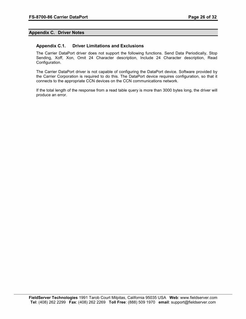
Appendix C. Driver Notes
Appendix C.1. Driver Limitations and Exclusions
The Carrier DataPort driver does not support the following functions. Send Data Periodically, Stop Sending, Xoff, Xon, Omit 24 Character description, Include 24 Character description, Read Configuration.
The Carrier DataPort driver is not capable of configuring the DataPort device. Software provided by the Carrier Corporation is required to do this. The DataPort device requires configuration, so that it connects to the appropriate CCN devices on the CCN communications network. If the total length of the response from a read table query is more than 3000 bytes long, the driver will produce an error.
FS-8700-86 Carrier DataPort Page 27 of 32
FieldServer Technologies 1991 Tarob Court Milpitas, California 95035 USA Web: www.fieldserver.com Tel: (408) 262 2299 Fax: (408) 262 2269 Toll Free: (888) 509 1970 email: [email protected]
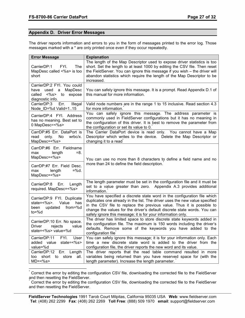
Appendix D. Driver Error Messages
The driver reports information and errors to you in the form of messages printed to the error log. Those messages marked with a * are only printed once even if they occur repeatedly.
Error Message Explanation
CarrierDP:1 FYI. The MapDesc called <%s> is too short
The length of the Map Descriptor used to expose driver statistics is too short. Set the length to at least 1000 by editing the CSV file. Then reset the FieldServer. You can ignore this message if you wish – the driver will abandon statistics which require the length of the Map Descriptor to be increased.
CarrierDP:2 FYI. You could have used a MapDesc called <%s> to expose diagnostic info.
You can safely ignore this message. It is a prompt. Read Appendix D.1 of this manual for more information.
CarrierDP:3 Err. Illegal Node_ID=%d Valid=1..15
Valid node numbers are in the range 1 to 15 inclusive. Read section 4.3 for more information.
*
CarrierDP:4 FYI. Address has no meaning. Best set to 0 MapDesc=<%s>
You can safely ignore this message. The address parameter is commonly used in FieldServer configurations but it has no meaning in the configuration of this driver. It is best to remove the parameter from the configuration or set its value to 0.
*
CarrDP:#5 Err. DataPort is read only. No wrbc/x. MapDesc=<%s>
The Carrier DataPort device is read only. You cannot have a Map Descriptor which writes to the device. Delete the Map Descriptor or changing it to a read
*
CarrDP:#6 Err. Fieldname max length =8. MapDesc=<%s>
CarrDP:#7 Err. Field Desc. max length =%d. MapDesc=<%s>
You can use no more than 8 characters to define a field name and no more than 24 to define the field description.
*
CarrierDP:8 Err. Length required. MapDesc=<%s>
The length parameter must be set in the configuration file and it must be set to a value greater than zero. Appendix A.3 provides additional information.
*
CarrierDP:9 FYI. Duplicate state=<%s>. Value has been updated from=%d to=%d
You have specified a discrete state word in the configuration file which duplicates one already in the list. The driver uses the new value specified in the CSV file to replace the previous value. Thus it is possible to change the values for the driver’s default discrete state words. You can safely ignore this message; it is for your information only.
CarrierDP:10 Err. No space. Driver rejects value state=<%s> value=%d
The driver has limited space to store discrete state keywords added in the configuration file. The maximum is 150 words including the driver’s defaults. Remove some of the keywords you have added to the configuration file
*
CarrierDP:11 FYI. User added value state=<%s> value=%d
You can safely ignore this message; it is for your information only. Each time a new discrete state word is added to the driver from the configuration file, the driver reports the new word and its value.
CarrierDP:12 Err. Length too short to store all. MD=<%s>
The driver reports that the read table command resulted in more variables being returned than you have reserved space for (with the length parameter). Increase the length parameter.
*
* Correct the error by editing the configuration CSV file, downloading the corrected file to the FieldServer and then resetting the FieldServer. * Correct the error by editing the configuration CSV file, downloading the corrected file to the FieldServer and then resetting the FieldServer.

FS-8700-86 Carrier DataPort Page 28 of 32
FieldServer Technologies 1991 Tarob Court Milpitas, California 95035 USA Web: www.fieldserver.com Tel: (408) 262 2299 Fax: (408) 262 2269 Toll Free: (888) 509 1970 email: [email protected]
Error Message Explanation
CarrierDP:13 FYI. Diagnostic send error #1 response.
CarrierDP:14 FYI. Diagnostic cancelled slave response
These messages are for FieldServer engineers. If any either is ever printed in the error log please call FieldServer support and report the message.
CarrDP:#15 Err. Field Units required. MapDesc=<%s>
A server side Map Descriptor requires that the Engineering units are defined. More information about this field is provided in section 0 and Appendix A.1
CarrDP:#16 FYI. Use DA_Byte_Name for server status values. MD=<%s>
This message may be safely ignored. It is provided for your information only. It reminds you that you can use a secondary Data Array connected to the server side Map Descriptor to store ‘status’ value which will be returned when the server is polled. This is an alternate way of allowing the driver to determine the ‘status’ values. More information on status values is provided in Appendix A.1
CarrDP:#17 FYI. Use DA_Byte_Name for 'status' value storage. MD=<%s>
This message may be safely ignored. It is provided for your information only. It reminds you that you can use a secondary Data Array connected to the Client side Map Descriptor to have the driver store ‘status’ value when a poll response is obtained. If this secondary array is not defined then the status values are ignored. More information on status values is provided in Appendix A.1
CarrDP:#18 FYI. Use DA_Float_Name for 'units' value storage. MD=<%s>
This message may be safely ignored. It is provided for your information only. It reminds you that you can use a secondary Data Array connected to the Client side Map Descriptor to have the driver store ‘engineering units’ values when a poll response is obtained. If this secondary array is not defined then the ‘units’ values are ignored. More information on ‘units’ values is provided in Appendix A.1
CarrDP:#19 Err. 'Table_Name' has no meaning. MapDesc=<%s>
CarrDP:#20 Err. 'Field_Name' has no meaning. MapDesc=<%s>
On the Client side the parameters ‘Table_Name’ and ‘Field_Name’ have no meaning and must be removed from the Map Descriptor.
*
CarrDP:#21 Err. 'On_String' required. MapDesc=<%s>
CarrDP:#22 Err. 'Field_Name' required. MapDesc=<%s>
CarrDP:#23 Err. 'Field_Desc' required. MapDesc=<%s>
On the server side, each Map Descriptor must have these parameters defined. Read section 0 and review the example in section 1.1.1 for more information.
*
CarrDP:#24 Err. MD=<%s> discrete state word not recognized.
On the line immediately following this error the driver reports the response that generated the error. The driver will store a value that is the ASCII code for the first character of the discrete state reported. Identification of the unrecognized discrete state word as well as information on how to extend the list of recognized discrete state words is provided in Appendix A.4.1.
*
CarrDP:#25 Err. This driver The length of the response from each different Carrier device and for
* Correct the error by editing the configuration CSV file, downloading the corrected file to the FieldServer and then resetting the FieldServer.
FS-8700-86 Carrier DataPort Page 29 of 32
FieldServer Technologies 1991 Tarob Court Milpitas, California 95035 USA Web: www.fieldserver.com Tel: (408) 262 2299 Fax: (408) 262 2269 Toll Free: (888) 509 1970 email: [email protected]
Error Message Explanation
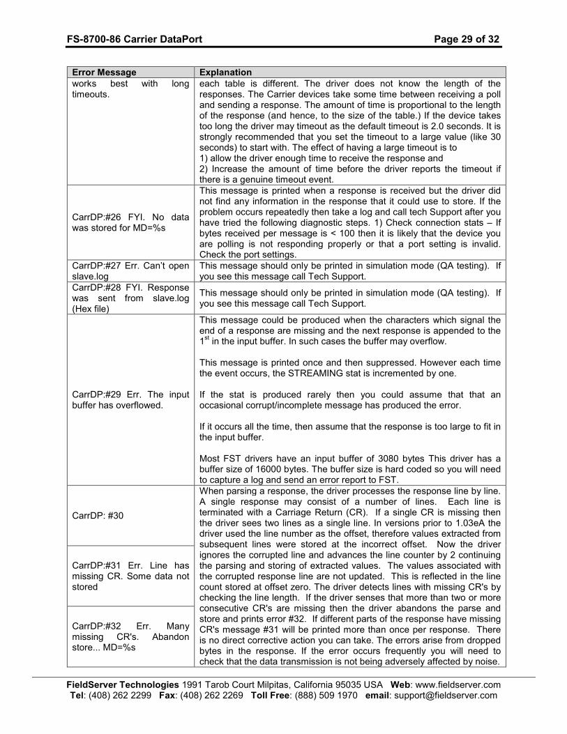
works best with long timeouts.
each table is different. The driver does not know the length of the responses. The Carrier devices take some time between receiving a poll and sending a response. The amount of time is proportional to the length of the response (and hence, to the size of the table.) If the device takes too long the driver may timeout as the default timeout is 2.0 seconds. It is strongly recommended that you set the timeout to a large value (like 30 seconds) to start with. The effect of having a large timeout is to 1) allow the driver enough time to receive the response and 2) Increase the amount of time before the driver reports the timeout if there is a genuine timeout event.
CarrDP:#26 FYI. No data was stored for MD=%s
This message is printed when a response is received but the driver did not find any information in the response that it could use to store. If the problem occurs repeatedly then take a log and call tech Support after you have tried the following diagnostic steps. 1) Check connection stats – If bytes received per message is < 100 then it is likely that the device you are polling is not responding properly or that a port setting is invalid. Check the port settings.
CarrDP:#27 Err. Can’t open slave.log
This message should only be printed in simulation mode (QA testing). If you see this message call Tech Support.
CarrDP:#28 FYI. Response was sent from slave.log (Hex file)
This message should only be printed in simulation mode (QA testing). If you see this message call Tech Support.
CarrDP:#29 Err. The input buffer has overflowed.
This message could be produced when the characters which signal the end of a response are missing and the next response is appended to the 1st in the input buffer. In such cases the buffer may overflow.
This message is printed once and then suppressed. However each time the event occurs, the STREAMING stat is incremented by one. If the stat is produced rarely then you could assume that that an occasional corrupt/incomplete message has produced the error. If it occurs all the time, then assume that the response is too large to fit in the input buffer. Most FST drivers have an input buffer of 3080 bytes This driver has a buffer size of 16000 bytes. The buffer size is hard coded so you will need to capture a log and send an error report to FST.
CarrDP: #30
CarrDP:#31 Err. Line has missing CR. Some data not stored
CarrDP:#32 Err. Many missing CR's. Abandon store... MD=%s
When parsing a response, the driver processes the response line by line. A single response may consist of a number of lines. Each line is terminated with a Carriage Return (CR). If a single CR is missing then the driver sees two lines as a single line. In versions prior to 1.03eA the driver used the line number as the offset, therefore values extracted from subsequent lines were stored at the incorrect offset. Now the driver ignores the corrupted line and advances the line counter by 2 continuing the parsing and storing of extracted values. The values associated with the corrupted response line are not updated. This is reflected in the line count stored at offset zero. The driver detects lines with missing CR's by checking the line length. If the driver senses that more than two or more consecutive CR's are missing then the driver abandons the parse and store and prints error #32. If different parts of the response have missing CR's message #31 will be printed more than once per response. There is no direct corrective action you can take. The errors arise from dropped bytes in the response. If the error occurs frequently you will need to check that the data transmission is not being adversely affected by noise.

FS-8700-86 Carrier DataPort Page 30 of 32
FieldServer Technologies 1991 Tarob Court Milpitas, California 95035 USA Web: www.fieldserver.com Tel: (408) 262 2299 Fax: (408) 262 2269 Toll Free: (888) 509 1970 email: [email protected]
Error Message Explanation
CarrDP:#33 Err. DataPort responded with Err=%d. Device=%s
There DataPort device responded but the response reports an error. The error number is printed in the message. The message also reports the name of the node that was polled. The following 6 errors are documented. For other errors contact the Carrier Vendor. #1 Invalid Command : The digit 1 returned as an error code means that the last ASCII character sent to the DATAPORT by the off-network device is not one that the DATAPORT recognizes as a command. #2 No Display Table : The digit 2 returned as an error code means that the off-network device has commanded the DATAPORT to transmit data from a controller that is properly configured in the DATAPORT, but the controller does not contain a point display table. #3 CCN Bus Communication Error: The digit 3 returned as an error code means that the DATAPORT cannot transmit data from the requested controller because a communication error occurred while the DATAPORT was acquiring data from that controller. #4 Database Full : The digit 4 returned as an error code means that the off-network device has commanded the DATAPORT to transmit data from a controller that is properly configured in the DATAPORT, but the controller is beyond the 900 point limit. For example, if controllers 1 through 10 each contain 90 points, a command for the DATAPORT to transmit data from controller 11, 12, 13, 14, or 15 will result in error code 4. #5 DATAPORT Busy : The digit 5 returned as an error code means that a static data update is in progress, preventing the DATAPORT from responding successfully to a Send Controller Data Command or a Send Data Periodically command. #6 Controller Not Configured : The digit 6 returned as an error code means that the off-network device has commanded the DATAPORT to transmit data from a controller that is not configured in the DATAPORT. For example, if only controllers 1 through 5 are configured in the DATAPORT, a command of 0 (Send Controller Data for Controller 15) will result in error code 6.
CarrDP:#99 Err. Cant open INI file for response.
This message should only be printed in simulation mode (QA testing). If you see this message call Tech Support.

FS-8700-86 Carrier DataPort Page 31 of 32
FieldServer Technologies 1991 Tarob Court Milpitas, California 95035 USA Web: www.fieldserver.com Tel: (408) 262 2299 Fax: (408) 262 2269 Toll Free: (888) 509 1970 email: [email protected]
Appendix D.1. Driver Stats
The driver reports statistics according to the FieldServer standards. The following notes describe some aspects of standard statistic reporting which are peculiar to this driver.
• All error responses from the Carrier DataPort device are recorded as PROTOCOL ERRORS, In addition to the standard FieldServer communication statistics described above and in the FieldServer Instruction Manual, this driver can also expose some driver statistics by writing data to a Data Array. A special Map Descriptor is required. The driver recognizes the Map Descriptor by its name which must be "CarrierDP-stats”. The following example shows how this special Map Descriptor can be configured. You can copy this section of text directly into your CSV file.
Nodes Node_Name , Station, Protocol CarrDP_stats , 1 , CarrierDP
Data_Arrays Data_Array_Name , Data_Format, Data_Array_Length DA_CARRIERDP_STATS , UINT32 , 2000
Map_Descriptors Map_Descriptor_Name, Data_Array_Name , Data_Array_Offset, Function, Node_Name , Length, CarrierDP-Stats , DA_CARRIERDP_STATS, 0 , passive , CarrDP_stats, 500
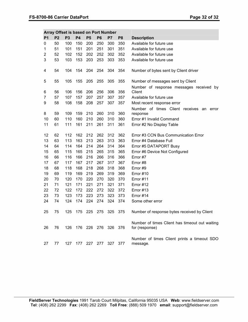
When the driver sees this Map Descriptor it uses the Data Array DA_CARRIER_STATS (in this example) to store driver specific statistics. Only one of these Map Descriptors may be specified per FieldServer. The driver stores the following data. The location in the Data Array is obtained by multiplying the port number by 50 and then using the location offset indicated in the table below.
FS-8700-86 Carrier DataPort Page 32 of 32
FieldServer Technologies 1991 Tarob Court Milpitas, California 95035 USA Web: www.fieldserver.com Tel: (408) 262 2299 Fax: (408) 262 2269 Toll Free: (888) 509 1970 email: [email protected]
Array Offset is based on Port Number
P1 P2 P3 P4 P5 P6 P7 P8 Description
0 50 100 150 200 250 300 350 Available for future use
1 51 101 151 201 251 301 351 Available for future use
2 52 102 152 202 252 302 352 Available for future use
3 53 103 153 203 253 303 353 Available for future use
4 54 104 154 204 254 304 354 Number of bytes sent by Client driver
5 55 105 155 205 255 305 355 Number of messages sent by Client
6 56 106 156 206 256 306 356 Number of response messages received by Client
7 57 107 157 207 257 307 357 Available for future use
9 58 108 158 208 257 307 357 Most recent response error
8 59 109 159 210 260 310 360 Number of times Client receives an error response
10 60 110 160 210 260 310 360 Error #1 Invalid Command
11 61 111 161 211 261 311 361 Error #2 No Display Table
12 62 112 162 212 262 312 362 Error #3 CCN Bus Communication Error
13 63 113 163 213 263 313 363 Error #4 Database Full
14 64 114 164 214 264 314 364 Error #5 DATAPORT Busy
15 65 115 165 215 265 315 365 Error #6 Device Not Configured
16 66 116 166 216 266 316 366 Error #7
17 67 117 167 217 267 317 367 Error #8
18 68 118 168 218 268 318 368 Error #9
19 69 119 169 219 269 319 369 Error #10
20 70 120 170 220 270 320 370 Error #11
21 71 121 171 221 271 321 371 Error #12
22 72 122 172 222 272 322 372 Error #13
23 73 123 173 223 273 323 373 Error #14
24 74 124 174 224 274 324 374 Some other error
25 75 125 175 225 275 325 375 Number of response bytes received by Client
26 76 126 176 226 276 326 376 Number of times Client has timeout out waiting for (response)
27 77 127 177 227 277 327 377 Number of times Client prints a timeout SDO message.