driver information system - t e x t f i l e...
TRANSCRIPT

DI-1
DRIVER INFORMATION SYSTEM
K ELECTRICAL
CONTENTS
C
D
E
F
G
H
I
J
L
M
SECTION
A
B
DI
Revision; 2004 April 2003 G35 Sedan
DRIVER INFORMATION SYSTEM
PRECAUTION ............................................................ 3Precautions for Supplemental Restraint System (SRS) “AIR BAG” and “SEAT BELT PRE-TEN-SIONER” .................................................................. 3Wiring Diagrams and Trouble Diagnosis .................. 3
COMBINATION METERS ........................................... 4System Description .................................................. 4
UNIFIED CONTROL METER ................................ 4HOW TO CHANGE THE DISPLAY FOR ODO/TRIP METER ........................................................ 4POWER SUPPLY AND GROUND CIRCUIT ........ 4WATER TEMPERATURE GAUGE ........................ 5TACHOMETER ..................................................... 5FUEL GAUGE ....................................................... 5SPEEDOMETER ................................................... 5
CAN Communication ................................................ 5CAN Communication Unit ........................................ 5
TYPE 1/TYPE 3 .................................................... 6TYPE 2 .................................................................. 8
Component Parts and Harness Connector Location ..... 9Combination Meter ................................................. 10
CHECK ................................................................ 10Schematic ...............................................................11Wiring Diagram — METER —/With A/T (Up to Serial 329287*) ................................................................. 12Wiring Diagram — METER —/With A/T (From Serial 329288*) and with M/T ........................................... 13Terminals and Reference Value for Combination Meter ...................................................................... 14Meter/Gauges Operation and Odo/Trip Meter ........ 14
SELF-DIAGNOSIS FUNCTION .......................... 14HOW TO ALTERNATE DIAGNOSIS MODE ....... 14
How to Proceed With Trouble Diagnosis ................ 15Diagnosis Flow ....................................................... 15Power Supply and Ground Circuit Check ............... 16Trouble Diagnosis Chart by Symptom .................... 17
DIAGNOSIS RESULTS ....................................... 17Inspection/Fuel Level Sensor ................................. 18
FUEL GAUGE ..................................................... 18LOW-FUEL WARNING LAMP ............................. 18
Inspection/Engine Speed Signal ............................. 19Inspection/Water Temperature Signal .................... 19Inspection/Vehicle Speed Signal ............................ 19The Fuel Gauge Pointer Fluctuates, Indicator Wrong Value Or Varies ........................................... 20The Fuel Gauge Does Not Move to FULL position ... 20The Fuel Gauge Does Not Work ............................ 20Low Fuel Warning Lamp Illuminates at All Times or Does Not Illuminate ................................................ 21Electrical Components Inspection .......................... 21
FUEL LEVEL SENSOR UNIT CHECK ................ 21Removal and Installation for Combination Meter .... 21
REMOVAL ........................................................... 21INSTALLATION ................................................... 22
Disassembly and Assembly for Combination Meter ... 22DISASSEMBLY ................................................... 22ASSEMBLY ......................................................... 22
COMPASS ................................................................. 23System Description ................................................. 23
DIRECTION DISPLAY ......................................... 23Wiring Diagram — COMPASS — ........................... 24Power Supply and Ground Circuit Check for Com-pass ........................................................................ 25Fail-Safe System .................................................... 25
DESCRIPTION .................................................... 25Compass Does not Display. ................................... 26Compass Display “– – –”. ....................................... 26Forward Direction Indication Slips Off The Mark Or Incorrect. ................................................................. 27Compass Reading Remains Unchanged. .............. 27Calibration Procedure for Compass ....................... 28
CORRECTION FUNCTIONS OF COMPASS ...... 28INITIAL CORRECTION PROCEDURE FOR COMPASS ........................................................... 28
Removal and Installation of Compass .................... 29REMOVAL ........................................................... 29INSTALLATION ................................................... 29
WARNING LAMPS .................................................... 30Schematic ............................................................... 30Wiring Diagram — WARN — .................................. 31

DI-2Revision; 2004 April 2003 G35 Sedan
Oil Pressure Warning Lamp Stays Off (Ignition Switch ON) ............................................................. 37Oil Pressure Warning Lamp Does Not Turn Off (Oil Pressure Is Normal) ................................................ 38Component Inspection ............................................ 38
OIL PRESSURE SWITCH ................................... 38A/T INDICATOR ........................................................ 39
Wiring Diagram — AT/IND — ................................. 39A/T Indicator Does Not Illuminate ........................... 40
WARNING CHIME ..................................................... 41Component Parts and Harness Connector Location ... 41System Description ................................................. 41
FUNCTION .......................................................... 41IGNITION KEY WARNING CHIME ...................... 42LIGHT WARNING CHIME ................................... 42SEAT BELT WARNING CHIME ........................... 42
CAN Communication .............................................. 43CAN Communication Unit ....................................... 43
TYPE 1/TYPE 3 ................................................... 43TYPE 2 ................................................................ 45
Wiring Diagram — CHIME — ................................. 47
Terminals and Reference Value for BCM ................49How to Proceed With Trouble Diagnosis ................49Preliminary Check ...................................................49
INSPECTION FOR POWER SUPPLY AND GROUND CIRCUIT .............................................49
CONSULT-II Function .............................................50DIAGNOSTIC ITEMS DESCRIPTION .................50CONSULT-II BASIC OPERATION PROCEDURE
...51DATA MONITOR ..................................................51ACTIVE TEST ......................................................52SELF-DIAGNOSTIC RESULTS ...........................53
All Warnings Are Not Operated ...............................53Key Warning Chime Does Not Operate ..................55Light Warning Chime Does Not Operate .................57Seat Belt Warning Chime Does Not Operate ..........58
CLOCK ......................................................................60Wiring Diagram — CLOCK — .................................60Removal and Installation of Clock ...........................61
REMOVAL ............................................................61INSTALLATION ....................................................61

PRECAUTION
DI-3
C
D
E
F
G
H
I
J
L
M
A
B
DI
Revision; 2004 April 2003 G35 Sedan
PRECAUTION PFP:00011
Precautions for Supplemental Restraint System (SRS) “AIR BAG” and “SEAT BELT PRE-TENSIONER” AKS007VG
The Supplemental Restraint System such as “AIR BAG” and “SEAT BELT PRE-TENSIONER”, used alongwith a front seat belt, helps to reduce the risk or severity of injury to the driver and front passenger for certaintypes of collision. This system includes seat belt switch inputs and dual stage front air bag modules. The SRSsystem uses the seat belt switches to determine the front air bag deployment, and may only deploy one frontair bag, depending on the severity of a collision and whether the front occupants are belted or unbelted.Information necessary to service the system safely is included in the SRS and SB section of this Service Man-ual.WARNING: To avoid rendering the SRS inoperative, which could increase the risk of personal injury or death
in the event of a collision which would result in air bag inflation, all maintenance must be per-formed by an authorized NISSAN/INFINITI dealer.
Improper maintenance, including incorrect removal and installation of the SRS, can lead to per-sonal injury caused by unintentional activation of the system. For removal of Spiral Cable and AirBag Module, see the SRS section.
Do not use electrical test equipment on any circuit related to the SRS unless instructed to in thisService Manual. SRS wiring harnesses can be identified by yellow and/or orange harnesses orharness connectors.
Wiring Diagrams and Trouble Diagnosis AKS0008S
When you read wiring diagrams, refer to the followings: Refer to GI-14, "How to Read Wiring Diagrams" Refer to PG-3, "POWER SUPPLY ROUTING CIRCUIT" for power distribution circuitWhen you perform trouble diagnosis, refer to the followings: Refer to GI-10, "HOW TO FOLLOW TEST GROUPS IN TROUBLE DIAGNOSES" Refer to GI-26, "How to Perform Efficient Diagnosis for an Electrical Incident"

DI-4
COMBINATION METERS
Revision; 2004 April 2003 G35 Sedan
COMBINATION METERS PFP:24814
System Description AKS0008U
UNIFIED CONTROL METER Speedometer, odo/trip meter, tachometer, fuel gauge and water temperature gauge are controlled by the
unified meter control unit, which is built into the combination meter. Digital meter is adopted for odo/trip meter.*
*The record of the odo meter is kept even if the battery cable is disconnected. The record of the trip meteris erased when the battery cable is disconnected.
Odo/trip meter and A/T indicator segments can be checked in diagnosis mode. Meter/gauge can be checked in diagnosis mode.
HOW TO CHANGE THE DISPLAY FOR ODO/TRIP METER The vehicle speed signal and the memory signals from the meter memory circuit are processed by the
combination meter and the mileage is displayed. Depressing the odo/trip meter switch toggles the mode in the following order.
The odo/trip meter display mode toggling and trip display resetting can be identified by the amount of timethat elapses from pressing the odo/trip meter switch to releasing it.
When resetting with trip A displayed, only trip A display is reset (Trip B operates the same way).
POWER SUPPLY AND GROUND CIRCUITPower is supplied at all times through 10A fuse [No. 19, located in the fuse block (J/B)] to combination meter terminal 43.With the ignition switch in the ON or START position, power is supplied through 10A fuse [No. 14, located in the fuse block (J/B)] to combination meter terminals 41 and 42.With the ignition switch in the ACC or ON position, power is supplied through 10A fuse [No. 6, located in the fuse block (J/B)] to combination meter terminals 40.Ground is supplied to combination meter terminals 45 and 47 through body grounds M30 and M66.
SEL175W

COMBINATION METERS
DI-5
C
D
E
F
G
H
I
J
L
M
A
B
DI
Revision; 2004 April 2003 G35 Sedan
WATER TEMPERATURE GAUGEThe water temperature gauge indicates the engine coolant temperature.ECM provides an engine coolant temperature signal to combination meter for water temperature gauge withCAN communication line.
TACHOMETERThe tachometer indicates engine speed in revolutions per minute (rpm).ECM provides an engine speed signal to combination meter for tachometer with CAN communication line.
FUEL GAUGEThe fuel gauge indicates the approximate fuel level in the fuel tank.The fuel gauge is regulated by a variable ground signal supplied from body grounds M30 and M66 through terminal 2 and 5 of the fuel level sensor unit and fuel pump (main) through terminal 1 and 2 of the fuel level sensor unit (sub) and to combination meter terminal 17 for the fuel gauge.
SPEEDOMETERVDC/TCS/ABS control unit provides a vehicle speed signal to the combination meter for the speedometer withCAN communication line.
CAN Communication AKS0008V
CAN (Controller Area Network) is a serial communication line for real time application. It is an on-vehicle mul-tiplex communication line with high data communication speed and excellent error detection ability. Many elec-tronic control units are equipped onto a vehicle, and each control unit shares information and links with othercontrol units during operation (not independent). In CAN communication, control units are connected with 2communication lines (CAN H line, CAN L line) allowing a high rate of information transmission with less wiring.Each control unit transmits/receives data but selectively reads required data only.
CAN Communication Unit AKS0081B
×: Applicable*:For further information, refer to GI-47, "IDENTIFICATION NUMBER" .
Body type Sedan
Axle 2WD
Engine VQ35DE
TransmissionA/T
M/TUp to serial 329287* From serial 329288*
Brake control VDC
CAN communication unit
ECM × ×
TCM ×
Data link connector × ×
Combination meter × ×
BCM × ×
Steering angle sensor × ×
VDC/TCS/ABS control unit × ×
IPDM E/R × ×
CAN communication type DI-6, "TYPE 1/TYPE 3" DI-8, "TYPE 2"

DI-6
COMBINATION METERS
Revision; 2004 April 2003 G35 Sedan
TYPE 1/TYPE 3System Diagram
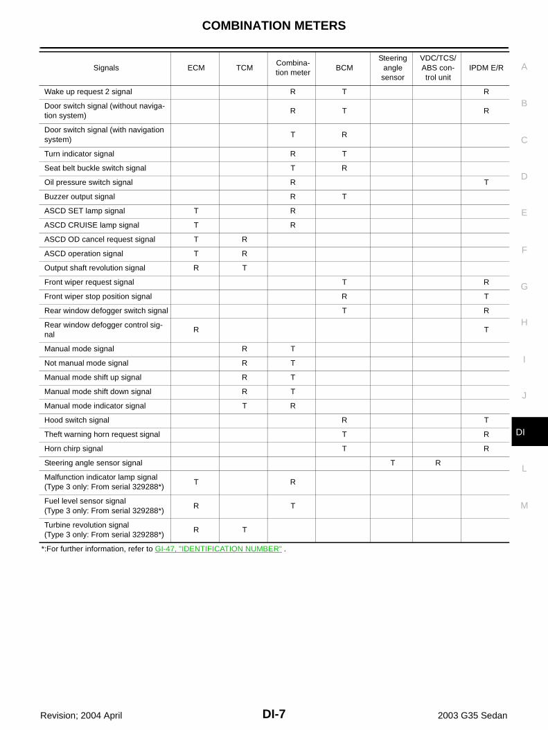
Input/Output Signal ChartT: Transmit R: Receive
SKIA1880E
Signals ECM TCMCombina-tion meter
BCMSteering
angle sensor
VDC/TCS/ABS con-trol unit
IPDM E/R
Engine torque signal T R
Engine speed signal T R R R
Engine coolant temperature signal T R R
Accelerator pedal position signal T R R
Closed throttle position signal T R
Wide open throttle position signal T R
Battery voltage signal T R
Stop lamp switch signal R T
Fuel consumption monitor signal T R
A/T self-diagnosis signal R T
A/T CHECK indicator lamp signal T R
A/T position indicator signal T R R
ABS operation signal R T
A/T shift schedule change demand signal
R T
A/C switch signal R T
A/C compressor request signal T R
A/C compressor feedback signal T R
Blower fan motor switch signal R T
Cooling fan motor operation signal T R
Position lights request signal R T R
Low beam request signal T R
Low beam status signal R T
High beam request signal R T R
High beam status signal R T
Front fog lights request signal T R
Vehicle speed signalR T
R R T R
Sleep request 1 signal R T
Sleep request 2 signal T R
Wake up request 1 signal R T R
COMBINATION METERS
DI-7
C
D
E
F
G
H
I
J
L
M
A
B
DI
Revision; 2004 April 2003 G35 Sedan
*:For further information, refer to GI-47, "IDENTIFICATION NUMBER" .
Wake up request 2 signal R T R
Door switch signal (without naviga-tion system)
R T R
Door switch signal (with navigation system)
T R
Turn indicator signal R T
Seat belt buckle switch signal T R
Oil pressure switch signal R T
Buzzer output signal R T
ASCD SET lamp signal T R
ASCD CRUISE lamp signal T R
ASCD OD cancel request signal T R
ASCD operation signal T R
Output shaft revolution signal R T
Front wiper request signal T R
Front wiper stop position signal R T
Rear window defogger switch signal T R
Rear window defogger control sig-nal
R T
Manual mode signal R T
Not manual mode signal R T
Manual mode shift up signal R T
Manual mode shift down signal R T
Manual mode indicator signal T R
Hood switch signal R T
Theft warning horn request signal T R
Horn chirp signal T R
Steering angle sensor signal T R
Malfunction indicator lamp signal(Type 3 only: From serial 329288*)
T R
Fuel level sensor signal(Type 3 only: From serial 329288*)
R T
Turbine revolution signal(Type 3 only: From serial 329288*)
R T
Signals ECM TCMCombina-tion meter
BCMSteering
angle sensor
VDC/TCS/ABS con-trol unit
IPDM E/R

DI-8
COMBINATION METERS
Revision; 2004 April 2003 G35 Sedan
TYPE 2System Diagram
Input/Output Signal ChartT: Transmit R: Receive
SKIA4474E
Signals ECMCombina-tion meter
BCMSteering
angle sen-sor
VDC/TCS/ABS con-trol unit
IPDM E/R
Engine speed signal T R R
Engine coolant temperature signal T R
Accelerator pedal position signal T R
Fuel consumption monitor signal T R
A/C switch signal R T
A/C compressor request signal T R
A/C compressor feedback signal T R
Blower fan motor switch signal R T
Cooling fan motor operation signal T R
Position lights request signal R T R
Low beam request signal T R
Low beam status signal R R T
High beam request signal R T R
High beam status signal R R T
Front fog lights request signal T R
Vehicle speed signalR T
R T R
Sleep request 1 signal R T
Sleep request 2 signal T R
Wake up request 1 signal R T
Wake up request 2 signal R T
Door switch signal (without navigation system) R T R
Door switch signal (with navigation system) T R
Turn indicator signal R T
Seat belt buckle switch signal T R
Oil pressure switch signal R T
Buzzer output signal R T
Malfunction indicator lamp signal T R
ASCD SET lamp signal T R
ASCD CRUISE lamp signal T R
Fuel level sensor signal R T

COMBINATION METERS
DI-9
C
D
E
F
G
H
I
J
L
M
A
B
DI
Revision; 2004 April 2003 G35 Sedan
Component Parts and Harness Connector Location AKS0008T
Front wiper request signal T R
Front wiper stop position signal R T
Rear window defogger switch signal T R
Rear window defogger control signal R R T
Hood switch signal R T
Theft warning horn request signal T R
Horn chirp signal T R
Steering angle sensor signal T R
Signals ECMCombina-tion meter
BCMSteering
angle sen-sor
VDC/TCS/ABS con-trol unit
IPDM E/R
PKIA3708E

DI-10
COMBINATION METERS
Revision; 2004 April 2003 G35 Sedan
Combination Meter AKS0008W
CHECK
SKIA4118E

COMBINATION METERS
DI-11
C
D
E
F
G
H
I
J
L
M
A
B
DI
Revision; 2004 April 2003 G35 Sedan
Schematic AKS0008X
TKWT1014E

DI-12
COMBINATION METERS
Revision; 2004 April 2003 G35 Sedan
Wiring Diagram — METER —/With A/T (Up to Serial 329287*) AKS0008Y
*:For further information, refer to “IDENTIFICATION NUMBER” in GI section.
TKWT0715E

COMBINATION METERS
DI-13
C
D
E
F
G
H
I
J
L
M
A
B
DI
Revision; 2004 April 2003 G35 Sedan
Wiring Diagram — METER —/With A/T (From Serial 329288*) and with M/T AKS007VH
*:For further information, refer to “IDENTIFICATION NUMBER” in GI section.
TKWT1015E

DI-14
COMBINATION METERS
Revision; 2004 April 2003 G35 Sedan
Terminals and Reference Value for Combination Meter AKS0008Z
Meter/Gauges Operation and Odo/Trip Meter AKS00090
SELF-DIAGNOSIS FUNCTION Odo/trip meter segment and A/T indicator segment operation can be checked in self-diagnosis mode. Meters/gauges can be checked in self-diagnosis mode.
HOW TO ALTERNATE DIAGNOSIS MODE1. Turn the ignition switch ON, and switch the odo/trip meter to “trip A” or “trip B”.
NOTE:If the diagnosis function is activated with the trip meter A displayed, the mileage on the trip meter A willindicate 0000.0 miles, but the actual trip mileage will be retained. (Trip B operates the same way.)
2. Turn ignition switch OFF.3. While pushing the odo/trip meter switch, turn ignition switch ON again.4. Check that the trip meter displays “0000.0”.5. Push the odo/trip meter switch at least 3 times. (Within 7 seconds after the ignition switch is turned ON.)6. All the segments on the odo/trip meter and A/T indicator illuminate, and simultaneously the low-fuel warn-
ing lamp indicator illuminates. At this time, the unified meter control unit is turned to diagnosis mode.NOTE:If any of the segments is not displayed, replace the combination meter.
Terminal No.
Wire Color
Item
Condition
Reference ValueIgnition switch
Operation or condition
17 W/B Fuel level sensor signal — —Refer to DI-21, "FUEL LEVEL SEN-SOR UNIT CHECK" .
19 W/G Vehicle speed signal (2-pulse) ONSpeedometer operated[When vehicle speed is approx. 40km/h (25MPH)]
27 R CAN-L — — —
28 L CAN-H — — —
40 LG Ignition switch (ACC) ACC — Battery voltage
41 G/Y Ignition switch (ON) ON — Battery voltage
42 G/Y Ignition switch (ON) ON — Battery voltage
43 R/W Battery power supply OFF — Battery voltage
45 B Ground ON — Approx. 0V
47 B Ground ON — Approx. 0V
ELF1080D
SKIA4119E

COMBINATION METERS
DI-15
C
D
E
F
G
H
I
J
L
M
A
B
DI
Revision; 2004 April 2003 G35 Sedan
7. Push the odo/trip meter switch. Each meter/gauge should indi-cate as shown in the figure while pushing odo/trip meter switch.(at this time, the low-fuel warning lamp goes off).
How to Proceed With Trouble Diagnosis AKS00091
1. Confirm the symptom or customer complaint.2. Perform diagnosis according to diagnosis flow. Refer to DI-15, "Diagnosis Flow" .3. According to the trouble diagnosis chart, repair or replace the cause of the trouble symptom. Refer to DI-
17, "Trouble Diagnosis Chart by Symptom" .4. Does the meter operate normally? If so, go to 5. If not, go to 2.5. INSPECTION END
Diagnosis Flow AKS00092
1. CHECK WARNING LAMP ILLUMINATION
1. Turn ignition switch ON.2. Check that warning lamps (such as MIL and oil pressure warning lamp) illuminate.Do warning lamps illuminate?YES >> GO TO 2.NO >> Check ignition power supply system of combination meter. Refer to DI-16, "Power Supply and
Ground Circuit Check" .
2. CHECK SELF-DIAGNOSIS OPERATION
Perform combination meter self-diagnosis. Refer to DI-14, "SELF-DIAGNOSIS FUNCTION" .Does self-diagnosis function operate?YES >> GO TO 3.NO >> Check battery power supply of combination meter and ground system. Refer to DI-16, "Power
Supply and Ground Circuit Check" .
3. CHECK ODO/TRIP METER OPERATION
Check segment display status of odo/trip meter.
Is the display normal?YES >> GO TO 4.NO >> Replace combination meter.
SKIA2097E
SKIA4119E

DI-16
COMBINATION METERS
Revision; 2004 April 2003 G35 Sedan
4. CHECK FUEL WARNING LAMP ILLUMINATION
During fuel warning lamp check, confirm illumination of fuel warning lamp.
OK or NGOK >> GO TO 5.NG >> Replace combination meter.
5. CHECK METER CIRCUIT
Check indication of each meter/gauge in self-diagnosis mode.OK or NGOK >> Go to diagnosis results. Refer to DI-17, "DIAGNOSIS
RESULTS" .NG >> Replace combination meter.
Power Supply and Ground Circuit Check AKS00093
1. CHECK FUSES
Check for blown combination meter fuses.
OK or NGOK >> GO TO 2.NG >> If fuse is blown, be sure to eliminate cause of problem before installing new fuse. Refer to PG-3,
"POWER SUPPLY ROUTING CIRCUIT" .
Condition of odo/trip meter switch Fuel warning lamp
Pushed Does not illuminate.
Released Illuminates.
SKIA2097E
Unit Power source Fuse No.
Combination meter
Battery 19
Ignition switch (ON) 14
Ignition switch (ACC) 6

COMBINATION METERS
DI-17
C
D
E
F
G
H
I
J
L
M
A
B
DI
Revision; 2004 April 2003 G35 Sedan
2. CHECK POWER SUPPLY CIRCUIT
1. Disconnect combination meter connector.2. Check voltage between combination meter and ground.
OK or NGOK >> GO TO 3.NG >> Check harness for open or short between combination meter and fuse.
3. CHECK GROUND CIRCUIT
1. Turn ignition switch OFF.2. Check continuity between combination meter and ground.
OK or NGOK >> INSPECTION ENDNG >> Check ground harness.
Trouble Diagnosis Chart by Symptom AKS00094
DIAGNOSIS RESULTS
Terminals Ignition switch position
(+)
(–) OFF ACC ONConnector
Terminal(Wire color)
M20
40 (LG)
Ground
0VBattery voltage
Battery voltage
41 (G/Y) 0V 0VBattery voltage
42 (G/Y) 0V 0VBattery voltage
43 (R/W)Battery voltage
Battery voltage
Battery voltage
SKIA1905E
Terminals
Continuity(+)
(–)Connector
Terminal(Wire color)
M2045 (B)
Ground Yes47 (B)
SKIA1906E
Trouble phenomenon Possible cause
Tachometer indication is malfunction. Refer to DI-19, "Inspection/Engine Speed Signal" .
Fuel warning lamp indication is irregular.Refer to DI-18, "Inspection/Fuel Level Sensor" .
Fuel gauge indication is malfunction.
Water temperature gauge indication is malfunction. Refer to DI-19, "Inspection/Water Temperature Signal" .
Indication is irregular for the speedometer and odo/trip meter. Refer to DI-19, "Inspection/Vehicle Speed Signal" .
Indications are irregular for more than one gauge. Replace combination meter.
A/T position indicator is malfunction. Refer to DI-40, "A/T Indicator Does Not Illuminate" .

DI-18
COMBINATION METERS
Revision; 2004 April 2003 G35 Sedan
Inspection/Fuel Level Sensor AKS00095
The following symptoms do not indicate a malfunction.
FUEL GAUGE Depending on vehicle position or driving circumstance, the fuel in the tank flows and the pointer may fluc-
tuate. If the vehicle is fueled with the ignition switch ON, the pointer will move slowly.
LOW-FUEL WARNING LAMPDepending on vehicle position or driving circumstance, the fuel in the tank flows and the warning lamp ON tim-ing may change.
1. CHECK HARNESS CONNECTOR
Check combination meter and fuel level sensor unit terminals (meter-side, unit-side harness-side) for loose-ness or bent terminals.OK or NGOK >> GO TO 2.NG >> Repair terminal or connector.
2. CHECK COMBINATION METER CIRCUIT
1. Disconnect combination meter connector and fuel level sensorunit (sub) connector.
2. Check continuity between combination meter harness connectorM19 terminal 17 (W/B) and fuel level sensor unit (sub) harnessconnector B28 terminal 1 (W/B).
3. Check continuity between combination meter harness connectorM19 terminal 17 (W/B) and ground.
OK or NGOK >> GO TO 3.NG >> Repair harness or connector.
3. CHECK FUEL LEVEL SENSOR CIRCUIT
1. Disconnect fuel level sensor unit and fuel pump (main) connec-tor.
2. Check continuity between fuel level sensor unit (sub) harnessconnector B28 terminal 2 (Y) and fuel level sensor unit and fuelpump (main) harness connector B27 terminal 2 (Y).
3. Check continuity between fuel level sensor unit (sub) harnessconnector B28 terminal 2 (Y) and ground.
OK or NGOK >> GO TO 4.NG >> Repair harness or connector.
Continuity should exist.
Continuity should not exist.SKIA1930E
Continuity should exist.
Continuity should not exist.SKIA1931E

COMBINATION METERS
DI-19
C
D
E
F
G
H
I
J
L
M
A
B
DI
Revision; 2004 April 2003 G35 Sedan
4. CHECK GROUND CIRCUIT
Check continuity between fuel level sensor unit and fuel pump(main) harness connector B27 terminal 5 (B) and ground.
OK or NGOK >> GO TO 5.NG >> Repair harness or connector.
5. CHECK FUEL LEVEL SENSOR
Check fuel level sensor units. Refer to DI-21, "FUEL LEVEL SENSOR UNIT CHECK" .OK or NGOK >> GO TO 6.NG >> Replace fuel level sensor unit and fuel pump (main) or fuel level sensor unit
6. CHECK INSTALLATION CONDITION
Check fuel level sensor unit installation, and check whether the float arm interferes or binds with any of theinternal components in the fuel tank.OK or NGOK >> Replace combination meter.NG >> Install fuel level sensor unit properly.
Inspection/Engine Speed Signal AKS00096
1. CHECK ECM SELF-DIAGNOSIS
Perform ECM self-diagnosis. Refer to EC-15, "APPLICATION NOTICE" .OK or NGOK >> Replace combination meter.NG >> Perform “Diagnostic Procedure” in displayed DTC.
Inspection/Water Temperature Signal AKS00098
1. CHECK ECM SELF-DIAGNOSIS
Preform the ECM self-diagnosis. Refer to EC-15, "APPLICATION NOTICE" . OK or NGOK >> Replace combination meter.NG >> Perform “Diagnostic Procedure” in displayed DTC.
Inspection/Vehicle Speed Signal AKS00099
1. CHECK VDC/TCS/ABS CONTROL UNIT SELF-DIAGNOSIS
Preform VDC/TCS/ABS control unit self-diagnosis. Refer to BRC-35, "CONSULT-II Functions" .OK or NGOK >> Replace combination meter.NG >> Check applicable parts.
Continuity should exist.
SKIA1932E

DI-20
COMBINATION METERS
Revision; 2004 April 2003 G35 Sedan
The Fuel Gauge Pointer Fluctuates, Indicator Wrong Value Or Varies AKS0009B
1. CHECK FUEL GAUGE FLUCTUATION
Test drive vehicle to see if gauge fluctuates only during driving or before or after stopping.Does the indication value vary only during driving or before or after stopping?YES >> The pointer fluctuation may be caused by fuel level change in the fuel tank. Condition is normal.NO >> Ask the customer about the situation when the symptom occurs in detail, and perform the trouble
diagnosis.
The Fuel Gauge Does Not Move to FULL position AKS0009C
1. QUESTION 1
Does it take a long time for the pointer to move to FULL position?YES or NOYES >> GO TO 2.NO >> GO TO 3.
2. QUESTION 2
Was the vehicle fueled with the ignition switch ON?YES or NOYES >> Be sure to fuel the vehicle with the ignition switch OFF. Otherwise, it will take a long time to move
to FULL position because of the characteristic of the fuel gauge.NO >> GO TO 3.
3. QUESTION 3
Is the vehicle parked on an incline?YES or NOYES >> Check the fuel level indication with vehicle on a level surface.NO >> GO TO 4.
4. QUESTION 4
During driving, does the fuel gauge pointer move gradually toward EMPTY position?YES or NOYES >> Check fuel level sensor unit. Refer to DI-21, "FUEL LEVEL SENSOR UNIT CHECK" .NO >> The float arm may interfere or bind with any of the components in the fuel tank.
The Fuel Gauge Does Not Work AKS0009D
1. CHECK HARNESS CONNECTOR
Check combination meter and fuel level sensor unit terminals (meter-side, unit side and harness-side) for poorconnection and bend.OK or NGOK >> GO TO 2.NG >> Repair terminal or connector.
2. CHECK INSTALLATION CONDITION
Check fuel level sensor unit installation (refer to FL-5, "FUEL LEVEL SENSOR UNIT, FUEL FILTER ANDFUEL PUMP ASSEMBLY" , and check whether the float arm interferes or binds with any components insidethe fuel tank.OK or NGOK >> Fuel level sensor unit is OK.NG >> Check fuel level sensor. Refer to DI-18, "Inspection/Fuel Level Sensor" .

COMBINATION METERS
DI-21
C
D
E
F
G
H
I
J
L
M
A
B
DI
Revision; 2004 April 2003 G35 Sedan
Low Fuel Warning Lamp Illuminates at All Times or Does Not Illuminate AKS0009E
1. CHECK SELF-DIAGNOSIS
Perform combination meter self-diagnosis. Refer to DI-14, "Meter/Gauges Operation and Odo/Trip Meter" .OK or NGOK >> Check fuel level sensor unit. Refer to DI-21, "FUEL LEVEL SENSOR UNIT CHECK" .NG >> Replace combination meter.
Electrical Components Inspection AKS000EA
FUEL LEVEL SENSOR UNIT CHECKFor removal, refer to FL-5, "FUEL LEVEL SENSOR UNIT, FUEL FILTER AND FUEL PUMP ASSEMBLY" .
Fuel Level Sensor Unit and Fuel Pump (Main)Check the resistance between terminals 2 and 5.
*1 and *2: When float rod is in contact with stopper.
Fuel Level Sensor Unit (Sub)Check the resistance between terminals 1 and 2.
*1 and *2: When float rod is in contact with stopper.
Removal and Installation for Combination Meter AKS000EV
REMOVAL1. Remove column cover. Refer to PS-9, "STEERING COLUMN" .2. Remove combination switch. Refer to IP-10, "INSTRUMENT
PANEL ASSEMBLY" .3. Remove instrument lower cover. Refer to IP-10, "INSTRUMENT
PANEL ASSEMBLY" .4. Remove the screw (4) and remove cluster lid A and combination
meter assembly. Refer to IP-10, "INSTRUMENT PANELASSEMBLY" .
TerminalFloat position mm (in) Resistance value Ω
(+) (−)
2 5*1 Full 9.0 (0.35) Approx. 2 - 3
*2 Empty 175 (6.89) Approx.79 - 85
SKIA1136E
TerminalFloat position mm (in) Resistance value Ω
(+) (−)
1 2*1 Full 9.4 (0.37) Approx. 2 - 3
*2 Empty 179 (7.05) Approx. 41- 45
SKIA1137E
SKIA1083E

DI-22
COMBINATION METERS
Revision; 2004 April 2003 G35 Sedan
5. Disconnect connectors and remove combination meter.6. Disassembly cluster lid A and combination meter.
INSTALLATIONInstall in the reverse order of removal.
Disassembly and Assembly for Combination Meter AKS000EW
DISASSEMBLY1. Disengaged the tabs (8) to separate front cover.2. Remove screw (2) and remove plate.3. Disengaged the tabs (8) to separate upper housing.4. Remove bulbs.
ASSEMBLYAssembly in the reverse order of disassembly.
SKIA1084E
1. Front cover 2. Upper housing 3. Plate
4. Unified meter control unit assembly
SKIA1443E

COMPASS
DI-23
C
D
E
F
G
H
I
J
L
M
A
B
DI
Revision; 2004 April 2003 G35 Sedan
COMPASS PFP:24835
System Description AKS004FE
This unit displays earth magnetism and heading direction of vehicle.
DIRECTION DISPLAYPush the switch when the ignition key is in the “ON” or “START” position. The direction will be displayed.
SKIA1945E

DI-24
COMPASS
Revision; 2004 April 2003 G35 Sedan
Wiring Diagram — COMPASS — AKS004FF
TKWT0716E

COMPASS
DI-25
C
D
E
F
G
H
I
J
L
M
A
B
DI
Revision; 2004 April 2003 G35 Sedan
Power Supply and Ground Circuit Check for Compass AKS004FG
1. CHECK FUSE
Check 10A fuse [No. 12, located in fuse block (J/B)].OK or NGOK >> GO TO 2.NG >> If fuse is blown, be sure to eliminate case of problem before installing new fuse. Refer to PG-3,
"POWER SUPPLY ROUTING CIRCUIT" .
2. POWER SUPPLY CIRCUIT CHECK
1. Disconnect the compass connector. 2. Turn ignition switch ON.3. Check voltage between compass harness connector M81 termi-
nal 4 (Y/G) and ground.
OK or NGOK >> GO TO 3.NG >> Check harness for open or short between compass and
fuse.
3. GROUND CIRCUIT CHECK
1. Turn ignition switch OFF.2. Check continuity between compass harness connector M81 ter-
minal 1 (B) and ground.
OK or NGOK >> Inspection end.NG >> Repair or replace harness for ground circuit.
Fail-Safe System AKS004FH
DESCRIPTION If there is no response from display and A/C auto amp., previous display is kept for 10 minutes. After 10
minutes, “---” is displayed. (Only when there is no response continuously for 10 minutes.) If display and A/C auto amp. receives normal data within 10 minutes, normal operation will be recovered. If display and A/C auto amp. receives normal data while “---” is being displayed, normal operation will be
recovered. If ignition switch is turned OFF within 10 minutes: Previously retained data is displayed when ignition
switch is turned ON again. Then after 10 minutes, “---” is displayed. If response is never received after battery is turned ON, no data is retained. Therefore nothing is dis-
played for 10 minutes.
Battery voltage should exist.
SKIA4120E
Continuity should exist.
SKIA4121E

DI-26
COMPASS
Revision; 2004 April 2003 G35 Sedan
Compass Does not Display. AKS004FI
1. DISPLAY AND A/C AUTO AMP. SELF-DIAGNOSIS CHECK
Check display and A/C auto amp. self-diagnosis. Refer to ATC-62, "FUNCTION CONFIRMATION PROCE-DURE" .Does display and A/C auto amp. segments all displayed?Yes >> Check fail safe system. refer to DI-25, "Fail-Safe System" .No >> Replace display and A/C auto amp.
Compass Display “– – –”. AKS004FJ
1. FAIL-SAFE MODE CHECK
Check that fail-safe mode is not activated. Refer to DI-25, "Fail-Safe System" .Does be activated Fail-safe mode?Yes >> GO TO 3.No >> GO TO 2.
2. DISPLAY AND A/C AUTO AMP. SELF-DIAGNOSIS CHECK
Check display and A/C auto amp. self-diagnosis. Refer to ATC-62, "FUNCTION CONFIRMATION PROCE-DURE" .Does display and A/C auto amp. segments all displayed?Yes >> Inspection end.No >> Replace display and A/C auto amp.
3. POWER AND GROUND CIRCUIT CHECK
Check power and ground circuit. Refer to DI-25, "Power Supply and Ground Circuit Check for Compass" .OK or NGOK >> GO TO 4.NG >> Repair power and ground circuit.
4. COMPASS CIRCUIT CHECK
1. Turn ignition switch OFF.2. Disconnect compass connector and display and A/C auto amp.
connector.3. Check continuity between compass harness connector M81 ter-
minal 2 (L) and display and A/C auto amp. harness connectorM31 terminal 6 (L).
4. Check continuity between compass harness connector M81 ter-minal 3 (R) and display and A/C auto amp. harness connectorM31 terminal 7 (R).
QuestionOK >> GO TO 5.NG >> Repair harness or connector.
Continuity should exist.
SKIA4122E
Continuity should exist.
SKIA4123E

COMPASS
DI-27
C
D
E
F
G
H
I
J
L
M
A
B
DI
Revision; 2004 April 2003 G35 Sedan
5. COMPASS SIGNAL CHECK
1. Connect compass connector and display and A/C auto amp.connector.
2. Turn ignition switch ON.3. Check the signal between compass harness connector M81 ter-
minal 2 (L) and ground with CONSULT-ll or oscilloscope.
4. Check the signal between compass harness connector M81 ter-minal 3 (R) and ground with CONSULT-ll or oscilloscope.
OK or NGOK >> Replace display and A/C auto amp.NG >> Replace compass
Forward Direction Indication Slips Off The Mark Or Incorrect. AKS004FK
1. ZONE VARIATION CHANGE IS NOT DONE
Perform the zone variation change.OK or NGOK >> inspection end.NG >> Replace compass.
Compass Reading Remains Unchanged. AKS004FL
1. POWER AND GROUND CIRCUIT CHECK
Check power and ground circuit. Refer to DI-25, "Power Supply and Ground Circuit Check for Compass" .OK or NGOK >> Replace compass.NG >> Repair power and ground circuit.
SKIB0250E
RJIA0867E
SKIB0251E
RJIA0868E

DI-28
COMPASS
Revision; 2004 April 2003 G35 Sedan
Calibration Procedure for Compass AKS004FM
The difference between magnetic North and geographical North can sometimes be great enough to causefalse compass readings.In order for the compass to operate accurately in a particular zone, it must be calibrated using the followingprocedure.
CORRECTION FUNCTIONS OF COMPASSIf the direction is not shown correctly, carry out initial correction.
INITIAL CORRECTION PROCEDURE FOR COMPASS1. Pushing the “COMP” switch for about 10 seconds will enter the
initial correction mode. The direction bar starts blinking.2. Turn off all electrical equipment (turn signals, hazard signal, A/
C, lights, etc.). In a broad, flat, and safe location, drive the vehi-cle slowly [approximately 5 km/h (3 MPH) or less], and turn thevehicle 360° or more several times. When the direction appearson the display, correction is complete.
NOTE:The correct direction may not be shown in locations where the earth's magnetic field is disrupted, such as those listed below. Elevated bridges Railroad crossings Streets lined with large buildings Iron bridges Tunnels Locations above subways Underground parking areas Near large vehicles Electric power substations
SKIA2076E
SKIA1946E

COMPASS
DI-29
C
D
E
F
G
H
I
J
L
M
A
B
DI
Revision; 2004 April 2003 G35 Sedan
If display correction is performed in any of the above locations, accurate correction may not be possible. When heater or A/C fan speed is at maximum, the direction indicator display may move. This is not a mal-
function. It will return to normal when the heater or A/C fan speed is reduced.
Removal and Installation of Compass AKS004D4
REMOVAL1. Remove instrument panel and pad. Refer to IP-11, "Removal and Installation" .2. Remove screw (1), and remove compass.
INSTALLATIONInstall in the reverse order of removal.
PKIA2379E

DI-30
WARNING LAMPS
Revision; 2004 April 2003 G35 Sedan
WARNING LAMPS PFP:24814
Schematic AKS0009J
TKWT1016E

WARNING LAMPS
DI-31
C
D
E
F
G
H
I
J
L
M
A
B
DI
Revision; 2004 April 2003 G35 Sedan
Wiring Diagram — WARN — AKS0009K
TKWT1017E

DI-32
WARNING LAMPS
Revision; 2004 April 2003 G35 Sedan
TKWT0945E

WARNING LAMPS
DI-33
C
D
E
F
G
H
I
J
L
M
A
B
DI
Revision; 2004 April 2003 G35 Sedan
TKWT1018E

DI-34
WARNING LAMPS
Revision; 2004 April 2003 G35 Sedan
TKWT0947E

WARNING LAMPS
DI-35
C
D
E
F
G
H
I
J
L
M
A
B
DI
Revision; 2004 April 2003 G35 Sedan
TKWT0948E

DI-36
WARNING LAMPS
Revision; 2004 April 2003 G35 Sedan
TKWT0949E

WARNING LAMPS
DI-37
C
D
E
F
G
H
I
J
L
M
A
B
DI
Revision; 2004 April 2003 G35 Sedan
Oil Pressure Warning Lamp Stays Off (Ignition Switch ON) AKS0009R
1. CHECK BETWEEN IPDM E/R AND COMBINATION METER
Activate IPDM E/R auto active test. Refer to PG-21, "Auto Active Test" .Does auto active test activate?YES >> Replace combination meter.NO >> GO TO 2.
2. CHECK OIL PRESSURE SWITCH CIRCUIT
1. Turn ignition switch OFF.2. Disconnect IPDM E/R connector and oil pressure switch con-
nector.3. Check continuity between IPDM E/R harness connector E9 ter-
minal 50 (Y/B) and oil pressure switch harness connector F21terminal 1 (Y/B).
OK or NGOK >> GO TO 3.NG >> Repair harness or connector.
3. CHECK OIL PRESSURE SWITCH
Check oil pressure switch. Refer to DI-38, "OIL PRESSURE SWITCH" .OK or NGOK >> GO TO 4.NG >> Replace oil pressure switch.
4. CHECK IPDM E/R OUTPUT SIGNAL
1. Connect IPDM E/R connector.2. Turn ignition switch ON.3. Check voltage between IPDM E/R harness connector E9 termi-
nal 50 (Y/B) and ground.
OK or NGOK >> Perform BCM self-diagnosis.NG >> Replace IPDM E/R.
Continuity should exist.
SKIA4126E
Battery voltage should exist.
SKIA2144E

DI-38
WARNING LAMPS
Revision; 2004 April 2003 G35 Sedan
Oil Pressure Warning Lamp Does Not Turn Off (Oil Pressure Is Normal) AKS0009S
NOTE:For oil pressure inspection, refer to LU-6, "OIL PRESSURE CHECK" .
1. CHECK OIL PRESSURE SWITCH CIRCUIT
1. Disconnect IPDM E/R connector and oil pressure switch con-nector.
2. Check continuity between IPDM E/R harness connector E9 ter-minal 50 (Y/B) and ground.
OK or NGOK >> GO TO 2.NG >> Repair harness or connector.
2. CHECK IPDM E/R OUTPUT SIGNAL
1. Connect IPDM E/R connector.2. Turn ignition switch ON.3. Check voltage between IPDM E/R harness connector E9 termi-
nal 50 (Y/B) and body ground.
OK or NGOK >> Check oil pressure switch. Refer to DI-38, "OIL PRES-
SURE SWITCH" .NG >> Replace IPDM E/R.
Component Inspection AKS0009T
OIL PRESSURE SWITCHCheck continuity between the oil pressure switch and body ground.
Continuity should not exist.
SKIA2145E
Battery voltage should exist.
SKIA2144E
Condition Oil pressure kPa (kg/cm2 , psi) Continuity
Engine stopped Less than 29 (0.3, 4) Yes
Engine running More than 29 (0.3, 4) No
ELF0044D

A/T INDICATOR
DI-39
C
D
E
F
G
H
I
J
L
M
A
B
DI
Revision; 2004 April 2003 G35 Sedan
A/T INDICATOR PFP:24814
Wiring Diagram — AT/IND — AKS0009U
TKWT1019E

DI-40
A/T INDICATOR
Revision; 2004 April 2003 G35 Sedan
A/T Indicator Does Not Illuminate AKS0009W
1. CHECK COMBINATION METER SELF-DIAGNOSIS
Perform combination meter self-diagnosis. Refer to DI-14, "Meter/Gauges Operation and Odo/Trip Meter" .
YES or NOYES >> GO TO 2.NO >> Replace combination meter.
2. CHECK TCM SELF-DIAGNOSIS
Perform TCM self-diagnosis. Refer to AT-43, "TROUBLE DIAGNOSIS" .OK or NGOK >> Replace combination meter.NG >> Go to TCM trouble diagnosis.
Does all segments displayed?
WARNING CHIME
DI-41
C
D
E
F
G
H
I
J
L
M
A
B
DI
Revision; 2004 April 2003 G35 Sedan
WARNING CHIME PFP:24814
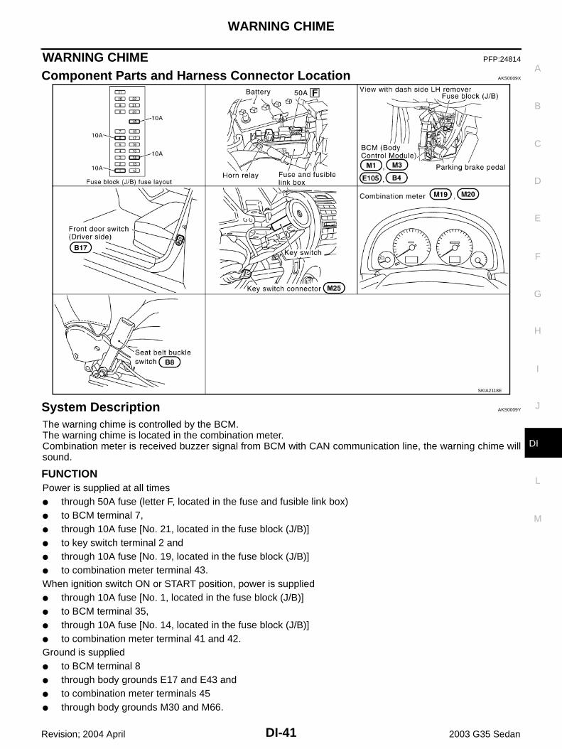
Component Parts and Harness Connector Location AKS0009X
System Description AKS0009Y
The warning chime is controlled by the BCM.The warning chime is located in the combination meter.Combination meter is received buzzer signal from BCM with CAN communication line, the warning chime willsound.
FUNCTIONPower is supplied at all times through 50A fuse (letter F, located in the fuse and fusible link box) to BCM terminal 7, through 10A fuse [No. 21, located in the fuse block (J/B)] to key switch terminal 2 and through 10A fuse [No. 19, located in the fuse block (J/B)] to combination meter terminal 43.When ignition switch ON or START position, power is supplied through 10A fuse [No. 1, located in the fuse block (J/B)] to BCM terminal 35, through 10A fuse [No. 14, located in the fuse block (J/B)] to combination meter terminal 41 and 42.Ground is supplied to BCM terminal 8 through body grounds E17 and E43 and to combination meter terminals 45 through body grounds M30 and M66.
SKIA2118E

DI-42
WARNING CHIME
Revision; 2004 April 2003 G35 Sedan
IGNITION KEY WARNING CHIMEWith the key inserted into the ignition switch, and the driver's door open, the warning chime will sound.Poweris supplied through key switch terminal 1 to BCM terminal 62, andGround is supplied (with navigation system) to combination meter terminal 7 through front door switch driver side terminal 1. Front door switch driver side is case grounded.Combination meter send door switch signal (door open signal) to BCM with CAN communication system. Ground is supplied (without navigation system) to BCM terminal 14 through front door switch driver side terminal 1. Front door switch driver side is case grounded.BCM detects key inserted into the ignition switch, and sends buzzer output signal (key warning signal) to com-bination meter with CAN communication line.When combination meter receives buzzer output signal (key warning signal), it sounds warning chime.
LIGHT WARNING CHIMEWith the key removed from the ignition switch, the driver's door open, and the lighting switch in 1ST or 2NDposition, the warning chime will sound. [Except when headlamp battery saver control operates (for 5 minutesafter ignition switch is turned to OFF or ACC position) and headlamps do not illuminate.]Signal is supplied from combination switch (lighting switch) terminals 1, 2, 3, 4, 5, 6, 7, 8, 9 and 10 to BCM terminals 40, 41, 42, 43, 47, 48, 49, 50, 51 and 52.
NOTE:BCM detected lighting switch in 1ST or 2ND position, refer to LT-120, "Combination Switch Reading Func-tion" .
Ground is supplied (with navigation system) to combination meter terminal 7 through front door switch driver side terminal 1. Front door switch driver side is case grounded.Combination meter send door switch signal (door open signal) to BCM with CAN communication system. Ground is supplied (without navigation system) from door switch driver side terminal 1 to BCM terminal 14.BCM detects headlamps are illuminated, and sends buzzer output signal (light warning signal) to combinationmeter with CAN communication line.When combination meter receives buzzer output signal (light warning signal), it sounds warning chime.
SEAT BELT WARNING CHIMEWith ignition switch turned ON and seat belt unfastened [seat belt buckle switch (driver side) ON], warningchime will sound for approximately 6 seconds.Ground is supplied from seat belt buckle switch (driver side) terminal 1 to combination meter terminal 1.Seat belt buckle switch (driver side) terminal 2 is grounded through body grounds B5 and B29.BCM receives buzzer output signal (seat belt unfastened signal) from combination meter over CAN communi-cation line, and sends buzzer output signal (seat belt warning signal) to combination meter with CAN commu-nication line.When combination meter receives buzzer output signal (seat belt warning signal), it sounds warning chime.

WARNING CHIME
DI-43
C
D
E
F
G
H
I
J
L
M
A
B
DI
Revision; 2004 April 2003 G35 Sedan
CAN Communication AKS0009Z
CAN (Controller Area Network) is a serial communication line for real time application. It is an on-vehicle mul-tiplex communication line with high data communication speed and excellent error detection ability. Many elec-tronic control units are equipped onto a vehicle, and each control unit shares information and links with othercontrol units during operation (not independent). In CAN communication, control units are connected with 2communication lines (CAN H line, CAN L line) allowing a high rate of information transmission with less wiring.Each control unit transmits/receives data but selectively reads required data only.
CAN Communication Unit AKS0081C
×: Applicable*:For further information, refer to GI-47, "IDENTIFICATION NUMBER" .
TYPE 1/TYPE 3System Diagram
Input/Output Signal ChartT: Transmit R: Receive
Body type Sedan
Axle 2WD
Engine VQ35DE
TransmissionA/T
M/TUp to serial 329287* From serial 329288*
Brake control VDC
CAN communication unit
ECM × ×
TCM ×
Data link connector × ×
Combination meter × ×
BCM × ×
Steering angle sensor × ×
VDC/TCS/ABS control unit × ×
IPDM E/R × ×
CAN communication type DI-43, "TYPE 1/TYPE 3" DI-45, "TYPE 2"
SKIA1880E
Signals ECM TCMCombina-tion meter
BCMSteering
angle sensor
VDC/TCS/ABS con-trol unit
IPDM E/R
Engine torque signal T R
Engine speed signal T R R R
Engine coolant temperature signal T R R
Accelerator pedal position signal T R R
Closed throttle position signal T R

DI-44
WARNING CHIME
Revision; 2004 April 2003 G35 Sedan
Wide open throttle position signal T R
Battery voltage signal T R
Stop lamp switch signal R T
Fuel consumption monitor signal T R
A/T self-diagnosis signal R T
A/T CHECK indicator lamp signal T R
A/T position indicator signal T R R
ABS operation signal R T
A/T shift schedule change demand signal
R T
A/C switch signal R T
A/C compressor request signal T R
A/C compressor feedback signal T R
Blower fan motor switch signal R T
Cooling fan motor operation signal T R
Position lights request signal R T R
Low beam request signal T R
Low beam status signal R T
High beam request signal R T R
High beam status signal R T
Front fog lights request signal T R
Vehicle speed signalR T
R R T R
Sleep request 1 signal R T
Sleep request 2 signal T R
Wake up request 1 signal R T R
Wake up request 2 signal R T R
Door switch signal (without naviga-tion system)
R T R
Door switch signal (with navigation system)
T R
Turn indicator signal R T
Seat belt buckle switch signal T R
Oil pressure switch signal R T
Buzzer output signal R T
ASCD SET lamp signal T R
ASCD CRUISE lamp signal T R
ASCD OD cancel request signal T R
ASCD operation signal T R
Output shaft revolution signal R T
Front wiper request signal T R
Front wiper stop position signal R T
Rear window defogger switch signal T R
Signals ECM TCMCombina-tion meter
BCMSteering
angle sensor
VDC/TCS/ABS con-trol unit
IPDM E/R

WARNING CHIME
DI-45
C
D
E
F
G
H
I
J
L
M
A
B
DI
Revision; 2004 April 2003 G35 Sedan
*:For further information, refer to GI-47, "IDENTIFICATION NUMBER" .
TYPE 2System Diagram
Input/Output Signal ChartT: Transmit R: Receive
Rear window defogger control sig-nal
R T
Manual mode signal R T
Not manual mode signal R T
Manual mode shift up signal R T
Manual mode shift down signal R T
Manual mode indicator signal T R
Hood switch signal R T
Theft warning horn request signal T R
Horn chirp signal T R
Steering angle sensor signal T R
Malfunction indicator lamp signal(Type 3 only: From serial 329288*)
T R
Fuel level sensor signal(Type 3 only: From serial 329288*)
R T
Turbine revolution signal(Type 3 only: From serial 329288*)
R T
Signals ECM TCMCombina-tion meter
BCMSteering
angle sensor
VDC/TCS/ABS con-trol unit
IPDM E/R
SKIA4474E
Signals ECMCombina-tion meter
BCMSteering
angle sen-sor
VDC/TCS/ABS con-trol unit
IPDM E/R
Engine speed signal T R R
Engine coolant temperature signal T R
Accelerator pedal position signal T R
Fuel consumption monitor signal T R
A/C switch signal R T
A/C compressor request signal T R
A/C compressor feedback signal T R
Blower fan motor switch signal R T
Cooling fan motor operation signal T R
Position lights request signal R T R
Low beam request signal T R
Low beam status signal R R T

DI-46
WARNING CHIME
Revision; 2004 April 2003 G35 Sedan
High beam request signal R T R
High beam status signal R R T
Front fog lights request signal T R
Vehicle speed signalR T
R T R
Sleep request 1 signal R T
Sleep request 2 signal T R
Wake up request 1 signal R T
Wake up request 2 signal R T
Door switch signal (without navigation system) R T R
Door switch signal (with navigation system) T R
Turn indicator signal R T
Seat belt buckle switch signal T R
Oil pressure switch signal R T
Buzzer output signal R T
Malfunction indicator lamp signal T R
ASCD SET lamp signal T R
ASCD CRUISE lamp signal T R
Fuel level sensor signal R T
Front wiper request signal T R
Front wiper stop position signal R T
Rear window defogger switch signal T R
Rear window defogger control signal R R T
Hood switch signal R T
Theft warning horn request signal T R
Horn chirp signal T R
Steering angle sensor signal T R
Signals ECMCombina-tion meter
BCMSteering
angle sen-sor
VDC/TCS/ABS con-trol unit
IPDM E/R

WARNING CHIME
DI-47
C
D
E
F
G
H
I
J
L
M
A
B
DI
Revision; 2004 April 2003 G35 Sedan
Wiring Diagram — CHIME — AKS000A1
TKWT0722E

DI-48
WARNING CHIME
Revision; 2004 April 2003 G35 Sedan
TKWT0721E

WARNING CHIME
DI-49
C
D
E
F
G
H
I
J
L
M
A
B
DI
Revision; 2004 April 2003 G35 Sedan
Terminals and Reference Value for BCM AKS000A2
How to Proceed With Trouble Diagnosis AKS000A3
1. Confirm the symptom or customer complaint.2. Understand operation description and function description. Refer to DI-41, "System Description" .3. Carry out the Preliminary Check. Refer to DI-49, "Preliminary Check" .4. Check symptom and repair or replace the cause of malfunction.5. Does the warning chime operate normally? If so, go to 6. If not, go to 4.6. INSPECTION END
Preliminary Check AKS000A4
INSPECTION FOR POWER SUPPLY AND GROUND CIRCUIT
1. CHECK FUSES
Check for blown BCM fuses.
Refer to DI-47, "Wiring Diagram — CHIME —" .OK or NGOK >> GO TO 2.NG >> If fuse is blown, be sure to eliminate cause of problem before installing new fuse. Refer to PG-3,
"POWER SUPPLY ROUTING CIRCUIT" .
Terminal No.
Wire color
Item
Condition
Reference valueIgnition switch
Measurement method
7 W/R Battery power supply OFF — Battery voltage
8 B Ground ON — Approx.0 V
14 W Front door switch signal OFF Driver doorON (open) Approx.0 V
OFF (closed) Approx.5 V
35 W/L Ignition switch (ON) ON — Battery voltage
40 Y/R Combination switch output 2
ON —
41 PU Combination switch output 3
42 L Combination switch output 4
43 GY Combination switch output 5
47 Y Combination switch output 1
48 W/R Combination switch input 1
ONLighting switch and wiper switch are OFF.
4.5 or more
49 W/G Combination switch input 2
50 W/L Combination switch input 3
51 G Combination switch input 4
52 G/R Combination switch input 5
62 B/P Key switch signal OFFKey is removed Approx.0 V
Key is inserted Battery voltage
70 L CAN H OFF — —
71 R CAN L OFF — —
SKIA1119J
UNIT POWER SOURCE FUSE No.
BCMBattery F
Ignition switch (ON) 1

DI-50
WARNING CHIME
Revision; 2004 April 2003 G35 Sedan
2. CHECK POWER SUPPLY CIRCUIT
1. Disconnect BCM connector.2. Check voltage between BCM connector and ground.
OK or NGOK >> GO TO 3.NG >> Check harness for open or short between BCM and fuse.
3. CHECK GROUND CIRCUIT
Check continuity between BCM and ground.
OK or NGOK >> INSPECTION ENDNG >> Repair harness or connector.
CONSULT-II Function AKS000A5
CONSULT-II executes the following functions by combining data reception and command transmission viathe communication line from BCM. Work support, self-diagnosis, data monitor, and active test display.
DIAGNOSTIC ITEMS DESCRIPTION
Terminals Ignition switch position
(+)
(–) OFF ACC ONConnector
Terminal (Wire color)
E105 7 (W/R)
Ground
Battery voltage
Battery voltage
Battery voltage
M1 35 (W/L) 0V 0VBattery voltage
SKIA2002E
Terminals
Continuity(+)
(–)Connector
Terminal (Wire color)
E105 8 (B) Ground Yes
PKIA0560E
BCM diagnosis position Diagnosis mode Description
KEY WARN ALMData monitor The input data to the BCM control unit is displayed in real time.
Active test Operation of electrical loads can be checked by sending driving signal to them.
LIGHT WARN ALMData monitor The input data to the BCM control unit is displayed in real time.
Active test Operation of electrical loads can be checked by sending driving signal to them.
SEAT BELT ALMData monitor The input data to the BCM control unit is displayed in real time.
Active test Operation of electrical loads can be checked by sending driving signal to them.
BCM Self-diagnostic BCM performs self-diagnosis of CAN communication and combination switch.

WARNING CHIME
DI-51
C
D
E
F
G
H
I
J
L
M
A
B
DI
Revision; 2004 April 2003 G35 Sedan
CONSULT-II BASIC OPERATION PROCEDURE1. With the ignition switch OFF, connect “CONSULT-II” and “CON-
SULT-II CONVERTER” to the data link connector, and turn theignition switch ON.
2. Touch “START (NISSAN BASED VHCL)”.
3. Touch “BCM”.If “BCM” is not indicated, go to GI-38, "CONSULT-II Data LinkConnector (DLC) Circuit" .
4. Touch “KEY WARN ALM”, “LIGHT WARN ALM”, “SEAT BELTALM” or “BCM C/U”.
5. Select “DATA MONITOR” “ACTIVE TEST” or “SELF-DIAGRESULTS”.
DATA MONITOROperation Procedure1. Touch “KEY WARN ALM”, “LIGHT WARN ALM” or “SEAT BELT ALM” on “SELECT TEST ITEM” screen.2. Touch “DATA MONITOR” on “SELECT DIAG MODE” screen.3. Touch “ALL SIGNALS” or “SELECTION FROM MENU” on “DATA MONITOR” screen.
PIIA1095E
SKIA3098E
LKIA0071E
LKIA0072E
ALL SIGNALS Monitors the main items.
SELECTION FROM MENU Selects and monitors the items.

DI-52
WARNING CHIME
Revision; 2004 April 2003 G35 Sedan
4. Touch “START”.5. If “SELECTION FROM MENU” is selected, touch the desired monitor item. If “ALL SIGNALS” is selected,
all items required to control are monitored.6. During monitoring, touching “RECORD” can start recording the monitored item status.
Data Monitor Item (Key Warning Chime)
Data Monitor Item (Light Warning Chime)
Data Monitor Item (Seat Belt Warning Chime)
ACTIVE TESTOperation Procedure1. Touch “KEY WARN ALM”, “LIGHT WARN ALM” or “SEAT BELT ALM” on “SELECT TEST ITEM” screen.2. Touch “ACTIVE TEST” on “SELECT DIAG MODE” screen.3. Touch the item to be tested, and check the operation.4. During the operation check, touching “OFF” deactivates the operation.
Active Test Item (Key Warning Chime)
Active Test Item (Light Warning Chime)
Active Test Item (Seat Belt Warning Chime)
Monitored item Description
IGN ON SW Indicates [ON/OFF] condition of ignition switch.
KEY ON SW Indicates [ON/OFF] condition of key switch.
DOOR SW-DR Indicates [ON/OFF] condition of front door switch driver side.
Monitored item Description
IGN ON SW Indicates [ON/OFF] condition of ignition switch.
DOOR SW-DR Indicates [ON/OFF] condition of front door switch driver side.
TAIL LAMP SW Indicates [ON/OFF] condition of lighting switch.
Monitored item Description
IGN ON SW Indicates [ON/OFF] condition of ignition switch.
SEAT BELT SW Indicates [ON/OFF] condition of seat belt buckle switch.
Test item Malfunction detecting condition
CHIMEThis test is able to check key warning chime operation. Key warning chime sounds for 2 seconds after touching “ON” on CONSULT-ll screen.
Test item Malfunction detecting condition
CHIMEThis test is able to check light warning chime operation. Light warning chime sounds for 2 seconds after touching “ON” on CONSULT-ll screen.
Test item Malfunction detecting condition
CHIMEThis test is able to check seat belt warning chime operation. Seat belt warning chime sounds for 2 seconds after touching “ON” on CONSULT-ll screen.

WARNING CHIME
DI-53
C
D
E
F
G
H
I
J
L
M
A
B
DI
Revision; 2004 April 2003 G35 Sedan
SELF-DIAGNOSTIC RESULTSOperation Procedure1. Touch “BCM C/U” on “DIAGNOSIS ITEM SELECTION” screen.2. Touch “SELF-DIAG RESULTS” on “SELECT DIAG MODE” screen.3. Self-diagnostic results are displayed.
Display Item List
NOTE:If “CAN communication [U1000]” is indicated, after printing the monitor item, go to “CAN system”. Refer toLAN-4, "CAN Communication Unit" .
All Warnings Are Not Operated AKS000A6
1. CHIME OPERATION INSPECTION
Select “KEY WARN ALM”, “LIGHT WARN ALM” or “SEAT BELTALM” on CONSULT-ll, and perform “CHIME” active test.Does chime sound?Yes >> GO TO 3.No >> GO TO 2.
2. BCM SELF-DIAGNOSIS
Select BCM on CONSULT-II, and perform “BCM C/U” self-diagnosis.Self-diagnostic results contentNo malfunction detected>> GO TO 3.CAN communication [U1000]>>After printing the monitor item, go to “CAN system”. Refer to LAN-4, "CAN
Communication Unit" .Diagnosis 1 - 5 systems open circuit>>Malfunction in combination switch system. Go to BCS-17, "Combina-
tion Switch Inspection According to Self-Diagnostic Results" according to self-diagnostic results.
Items to be displayed CONSULT-ll display Description
CAN communication CAN communication [U1000] Malfunction is detected in CAN communication.
Combination switch Diagnosis 1 - 5 systems open circuit Malfunction is detected in combination switch system.
WKIA0150E

DI-54
WARNING CHIME
Revision; 2004 April 2003 G35 Sedan
3. DATA MONITOR INSPECTION
Select BCM on CONSULT-II. Operate each switch with data monitor of “KEY WARN ALM”, “LIGHT WARNALM” or “SEAT BELT ALM” and check operation status of applicable switches.
KEY WARNING ALM
LIGHT WARNING ALM
SEAT BELT ALM
OK or NGOK >> Replace combination meter.NG >> GO TO 4 (With navigation system).
GO TO 5 (Without navigation system)
Switch operation CONSULT-II display Operation status
Ignition switch (ON)IGN ON SW
ON
Ignition switch (OFF) OFF
Ignition switch (key in switch)KEY ON SW
ON
Ignition switch (key out of switch) OFF
Driver door (open)DOOR SW-DR
ON
Driver door (closed) OFF
Switch operation CONSULT-II display Operation status
Ignition switch (ON)IGN ON SW
ON
Ignition switch (OFF) OFF
Driver door (open)DOOR SW-DR
ON
Driver door (closed) OFF
Lighting switch (1st position)TAIL LAMP SW
ON
Lighting switch (OFF) OFF
Switch operation CONSULT-II display Operation status
Ignition switch (ON)IGN ON SW
ON
Ignition switch (OFF) OFF
Seat belt switch (unfastened)SEAT BELT SW
ON
Seat belt switch (fastened) OFF
SKIA2003E
SKIA2004E
SKIA2005E

WARNING CHIME
DI-55
C
D
E
F
G
H
I
J
L
M
A
B
DI
Revision; 2004 April 2003 G35 Sedan
4. CHECK CONTINUITY DOOR SWITCH CIRCUIT (WITH NAVIGATION SYSTEM)
1. Disconnect combination meter connector and front door switchdriver side connector.
2. Check harness continuity between combination meter harnessconnector M19 terminal 7 (W) and front door switch driver sideharness connector B17 terminal 1 (W).
3. Check continuity between combination meter harness connectorM19 terminal 7 (W) and ground.
OK or NGOK >> GO TO 5.NG >> Repair harness or connector.
5. CHECK DOOR SWITCH CIRCUIT (WITHOUT NAVIGATION SYSTEM)
1. Disconnect BCM connector and front door switch driver sideconnector.
2. Check harness continuity between BCM harness connector B4terminal 14 (W) and front door switch driver side harness con-nector B17 terminal 1 (W).
3. Check continuity between BCM harness connector B4 terminal14 (W) and ground.
OK or NGOK >> GO TO 6NG >> Repair harness or connector.
6. CHECK DOOR SWITCH
Check front door switch driver side.
OK or NGOK >> Replace BCM.NG >> Replace driver side door switch.
Key Warning Chime Does Not Operate AKS000A7
1. CHECK FUSE
Check if the key switch fuse is blown. Refer to DI-47, "Wiring Diagram — CHIME —" .Is the fuse blown?Yes >> Replace fuse. Be sure to repair the cause of the problem before installing new fuse.No >> GO TO 2.
Continuity should exist.
Continuity should not exist.SKIA1998E
Continuity should exist.
Continuity should not exist.SKIA2082E
When driver side door switch is released
: Continuity should exist.
When driver side door switch is pushed
: Continuity should not exist.
PKIA3718E

DI-56
WARNING CHIME
Revision; 2004 April 2003 G35 Sedan
2. CHECK WARNING CHIME OPERATION
Check except for key warning chime operation.Dose warning chime sound?Yes >> GO TO 3No >> GO TO DI-53, "All Warnings Are Not Operated" .
3. CHECK KEY SWITCH INPUT SIGNAL
With CONSULT-llCheck key switch (“KEY ON SW”) in “DATA MONITOR” mode withCONSULT-ll.
Without CONSULT-llCheck voltage between BCM and ground.
OK or NGOK >> Key switch is OK.NG >> GO TO 4
4. CHECK KEY SWITCH (INSERT)
1. Disconnect key switch connector.2. Check continuity between key switch terminal 1 and 2.
OK or NGOK >> GO TO 5.NG >> Replace key switch.
When key is inserted to ignition key cylinder
: KEY ON SW ON
When key is removed from ignition key cylinder
: KEY ON SW OFF
SKIA1960E
Terminals
Condition Voltage (V)(+)
(–)Connector
Terminal (Wire color)
M3 62 (B/P) GroundKey is inserted Battery voltage
Key is removed 0
SKIA1961E
Terminal Condition Continuity
1 2Key is inserted Yes
Key is removed No
SKIA4111E

WARNING CHIME
DI-57
C
D
E
F
G
H
I
J
L
M
A
B
DI
Revision; 2004 April 2003 G35 Sedan
5. CHECK CONTINUITY BCM AND KEY SWITCH
1. Disconnect BCM connector.2. Check harness continuity between BCM harness connector M3
terminal 62 (B/P) and key switch harness connector M25 termi-nal 1 (B/P).
3. Check harness continuity between BCM harness connector M3terminal 62 (B/P) and ground.
OK or NGOK >> GO TO 6NG >> Repair harness or connector.
6. CHECK KEY SWITCH INPUT SIGNAL
Check voltage between key switch harness connector M25 terminal2 (L/W) and ground.
OK or NGOK >> Replace BCM. Refer to BCS-23, "Removal and Installa-
tion of BCM" .NG >> Check continuity open or short between key switch and
fuse.
Light Warning Chime Does Not Operate AKS000A8
1. CHECK WARNING CHIME OPERATION
Check except for headlamp warning chime operation.Dose warning chime sound?YES >> GO TO 2NO >> GO TO DI-53, "All Warnings Are Not Operated" .
2. CHECK DATA MONITOR
With “LIGHT WARN ALM” on the data monitor, confirm “TAIL LAMPSW” and “FR FOG SW” turn ON/OFF when lighting switch is oper-ated.
OK or NGOK >> Replace BCM. Refer to BCS-23, "Removal and Installa-
tion of BCM" .NG >> Replace lighting switch.
Continuity should exist.
Continuity should not exist.SKIA2001E
Battery voltage should exist.
SKIA1920E
Switch operation CONSULT-II display Operation status
Lighting switch (1st position)TAIL LAMP SW
ON
Lighting switch (OFF) OFF
SKIA2081E

DI-58
WARNING CHIME
Revision; 2004 April 2003 G35 Sedan
Seat Belt Warning Chime Does Not Operate AKS000A9
1. CHECK WARNING CHIME OPERATION
Check except for seat belt warning chime operation.Does warning chime sound?YES >> GO TO 2NO >> GO TO DI-53, "All Warnings Are Not Operated" .
2. SEAT BELT WARNING CHIME INPUT SIGNAL
With “SEAT BELT ALM” on the data monitor, confirm “SEAT BELTSW ” when the seat belt buckle switch is operated.
OK or NGOK >> Seat belt buckle switch is OK.NG >> GO TO 3.
3. COMBINATION METER INPUT SIGNAL
1. Turn ignition switch ON.2. Check voltage between Combination meter and ground.
OK or NGOK >> Replace combination meter.NG >> GO TO 4.
4. SEAT BELT BUCKLE SWITCH CHECK
1. Turn ignition switch OFF.2. Disconnect seat belt buckle switch (driver side) connector3. Check continuity seat belt buckle switch (driver side) harness
connector B8 terminals 1 and 2.
OK or NGOK >> GO TO 5.NG >> Replace seat belt buckle switch (driver side).
When seat belt is fastened : SEAT BELT SW OFFWhen seat belt is unfastened : SEAT BELT SW ON
SKIA2005E
Terminals
Condition Voltage (V)(+)
(–)Connec-tor
Terminal
M19 1 (SB) GroundSeat belt is fastened Battery voltage
Seat belt is unfastened 0SKIA1964E
Terminal Condition Continuity
1 2Seat belt is fastened No
Seat belt is unfastened Yes
SKIA1965E

WARNING CHIME
DI-59
C
D
E
F
G
H
I
J
L
M
A
B
DI
Revision; 2004 April 2003 G35 Sedan
5. CHECK SEAT BELT BUCKLE SWITCH CIRCUIT
1. Disconnect combination meter connector.2. Check harness continuity between combination meter harness
connector M19 terminal 1 (SB) and seat belt buckle switch(driver side) harness connector B8 terminal 1 (SB).
3. Check harness continuity between combination meter harnessconnector M19 terminal 1 (SB) and ground.
OK or NGOK >> GO TO 6.NG >> Repair harness or connector.
6. CHECK SEAT BELT BUCKLE SWITCH GROUND CIRCUIT
1. Disconnect BCM connector.2. Check harness continuity between seat belt buckle switch
(driver side) harness connector B8 terminal 2 (B) and ground.
OK or NGOK >> Replace combination meter.NG >> Repair harness or connector.
Continuity should exist.
Continuity should not exist.SKIA1999E
Continuity should exist.
SKIA2000E

DI-60
CLOCK
Revision; 2004 April 2003 G35 Sedan
CLOCK PFP:25820
Wiring Diagram — CLOCK — AKS000IM
TKWT0345E

CLOCK
DI-61
C
D
E
F
G
H
I
J
L
M
A
B
DI
Revision; 2004 April 2003 G35 Sedan
Removal and Installation of Clock AKS000IN
REMOVAL1. Remove the cluster lid finisher, refer to IP-10, "INSTRUMENT
PANEL ASSEMBLY" .2. Remove the screws (2), and remove clock.
INSTALLATIONInstall in the reverse order of removal.
SKIA2094E

DI-62
CLOCK
Revision; 2004 April 2003 G35 Sedan