driver controls exl a
TRANSCRIPT

DRIVER CONTROLS
C
D
E
SECTION EXLA
B
EXTERIOR LIGHTING SYSTEM
F
G
H
I
J
K
M
XL
N
O
P
CONTENTS
E
BASIC INSPECTION .................................... 3
DIAGNOSIS AND REPAIR WORKFLOW .......... 3Work Flow .................................................................3
FUNCTION DIAGNOSIS ............................... 6
HEADLAMP (HALOGEN TYPE) ......................... 6System Diagram ........................................................6System Description ...................................................6Component Parts Location ........................................6Component Description .............................................6
AUTO LIGHT SYSTEM ....................................... 8System Diagram ........................................................8System Description ...................................................8Component Parts Location ........................................9Component Description .............................................9
DAYTIME RUNNING LIGHT SYSTEM ..............11System Diagram ......................................................11System Description .................................................11Component Parts Location ......................................11Component Description ...........................................12
FRONT FOG LAMP ............................................13System Diagram ......................................................13System Description .................................................13Component Parts Location ......................................13Component Description ...........................................13
TURN SIGNAL AND HAZARD WARNING LAMPS ...............................................................14
System Diagram ......................................................14System Description .................................................14Component Parts Location ......................................15Component Description ...........................................15
PARKING, LICENSE PLATE AND TAIL LAMPS ...............................................................16
System Diagram ......................................................16System Description .................................................16
Component Parts Location ......................................16Component Description ...........................................17
COMBINATION SWITCH ..................................18System Description ..................................................18
DIAGNOSIS SYSTEM (BCM) ...........................19
COMMON ITEM .........................................................19COMMON ITEM : Diagnosis Description ................19COMMON ITEM : CONSULT-III Function ...............19
EXTERNAL LAMP .....................................................19EXTERNAL LAMP : CONSULT-III Function ............19
FLASHER ...................................................................21FLASHER : CONSULT-III Function (BCM - FLASHER) ...............................................................21
DIAGNOSIS SYSTEM (IPDM E/R) ...................22CONSULT - III Function (IPDM E/R) .......................22
COMPONENT DIAGNOSIS .........................23
POWER SUPPLY AND GROUND CIRCUIT ....23
BCM (BODY CONTROL MODULE) ..........................23BCM (BODY CONTROL MODULE) : Diagnosis Procedure ................................................................23
IPDM E/R (INTELLIGENT POWER DISTRIBU-TION MODULE ENGINE ROOM) ..............................23
IPDM E/R (INTELLIGENT POWER DISTRIBU-TION MODULE ENGINE ROOM) : Diagnosis Pro-cedure ......................................................................23
HEADLAMP (HI) CIRCUIT ................................24Description ...............................................................24Component Function Check ....................................24Diagnosis Procedure ...............................................24
HEADLAMP (LO) CIRCUIT ..............................26Description ...............................................................26Component Function Check ....................................26
EXL-1
Diagnosis Procedure .............................................. 26
FRONT FOG LAMP CIRCUIT ........................... 28Description .............................................................. 28Component Function Check ................................... 28Diagnosis Procedure .............................................. 28
PARKING LAMP CIRCUIT ................................ 30Description .............................................................. 30Component Function Check ................................... 30Diagnosis Procedure .............................................. 30
TURN SIGNAL LAMP CIRCUIT ........................ 33Description .............................................................. 33Component Function Check ................................... 33Diagnosis Procedure .............................................. 33
OPTICAL SENSOR ........................................... 36Description .............................................................. 36Component Function Check ................................... 36Diagnosis Procedure .............................................. 36
HEADLAMP ....................................................... 38Wiring Diagram ....................................................... 38
AUTO LIGHT SYSTEM ...................................... 42Wiring Diagram ....................................................... 42
DAYTIME LIGHT SYSTEM ................................ 48Wiring Diagram ....................................................... 48
FRONT FOG LAMP SYSTEM ........................... 55Wiring Diagram ....................................................... 55
TURN SIGNAL AND HAZARD WARNING LAMP SYSTEM ................................................. 58
Wiring Diagram ....................................................... 58
PARKING, LICENSE PLATE AND TAIL LAMPS SYSTEM ............................................... 65
Wiring Diagram ....................................................... 65
STOP LAMP ...................................................... 69Wiring Diagram ....................................................... 69
BACK-UP LAMP ................................................ 73Wiring Diagram ....................................................... 73
TRAILER TOW .................................................. 77Wiring Diagram ....................................................... 77
ECU DIAGNOSIS ........................................ 83
BCM (BODY CONTROL MODULE) .................. 83Description .............................................................. 83
IPDM E/R (INTELLIGENT POWER DISTRI-BUTION MODULE ENGINE ROOM) ................. 84
Description .............................................................. 84
SYMPTOM DIAGNOSIS ............................. 85
EXTERIOR LIGHTING SYSTEM SYMPTOMS ... 85Symptom Table ....................................................... 85
NORMAL OPERATING CONDITION ................ 87Description .............................................................. 87
BOTH SIDE HEADLAMPS DO NOT SWITCH TO HIGH BEAM ................................................. 88
Description .............................................................. 88Diagnosis Procedure ............................................... 88
BOTH SIDE HEADLAMPS (LO) ARE NOT TURNED ON ...................................................... 89
Description .............................................................. 89Diagnosis Procedure ............................................... 89
PARKING, LICENSE PLATE AND TAIL LAMPS ARE NOT TURNED ON ....................... 90
Description .............................................................. 90Diagnosis Procedure ............................................... 90
BOTH SIDE FRONT FOG LAMPS ARE NOT TURNED ON ...................................................... 91
Description .............................................................. 91Diagnosis Procedure ............................................... 91
ON-VEHICLE REPAIR ............................... 92
HEADLAMP ....................................................... 92Aiming Adjustment .................................................. 92Bulb Replacement ................................................... 93Removal and Installation ......................................... 94Disassembly and Assembly .................................... 95
AUTO LIGHT SYSTEM ..................................... 96Removal and Installation ......................................... 96
FRONT FOG LAMP ........................................... 97Aiming Adjustment .................................................. 97Bulb Replacement ................................................... 98Removal and Installation ......................................... 98
LIGHTING & TURN SIGNAL SWITCH .............. 99Removal and Installation ......................................... 99
HAZARD SWITCH ............................................100Removal and Installation ....................................... 100
STOP LAMP .....................................................101Bulb Replacement ................................................. 101Removal and Installation ....................................... 101
REAR COMBINATION LAMP ..........................102Bulb Replacement ................................................. 102Removal and Installation ....................................... 102
SERVICE DATA AND SPECIFICATIONS (SDS) ................................................................103
Headlamp .............................................................. 103Exterior Lamp ........................................................ 103
EXL-2

DIAGNOSIS AND REPAIR WORKFLOW
C
D
E
F
G
H
I
J
K
M
A
B
XL
N
O
P
< BASIC INSPECTION >
E
BASIC INSPECTIONDIAGNOSIS AND REPAIR WORKFLOW
Work Flow INFOID:0000000001621593
OVERALL SEQUENCE
JPLIA0089GB
EXL-3
DIAGNOSIS AND REPAIR WORKFLOW
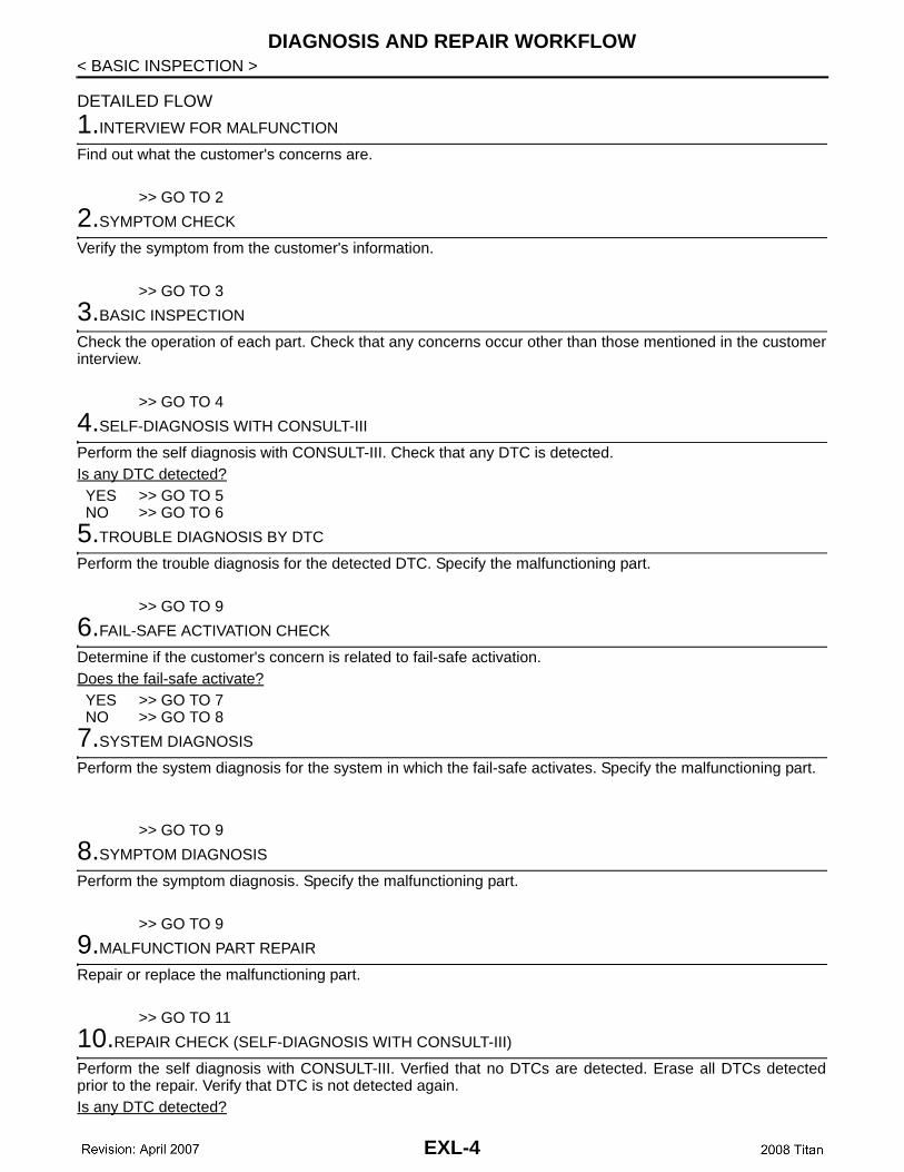
< BASIC INSPECTION >DETAILED FLOW
1.INTERVIEW FOR MALFUNCTION
Find out what the customer's concerns are.
>> GO TO 2
2.SYMPTOM CHECK
Verify the symptom from the customer's information.
>> GO TO 3
3.BASIC INSPECTION
Check the operation of each part. Check that any concerns occur other than those mentioned in the customerinterview.
>> GO TO 4
4.SELF-DIAGNOSIS WITH CONSULT-III
Perform the self diagnosis with CONSULT-III. Check that any DTC is detected.Is any DTC detected?YES >> GO TO 5NO >> GO TO 6
5.TROUBLE DIAGNOSIS BY DTC
Perform the trouble diagnosis for the detected DTC. Specify the malfunctioning part.
>> GO TO 9
6.FAIL-SAFE ACTIVATION CHECK
Determine if the customer's concern is related to fail-safe activation.Does the fail-safe activate?YES >> GO TO 7NO >> GO TO 8
7.SYSTEM DIAGNOSIS
Perform the system diagnosis for the system in which the fail-safe activates. Specify the malfunctioning part.
>> GO TO 9
8.SYMPTOM DIAGNOSIS
Perform the symptom diagnosis. Specify the malfunctioning part.
>> GO TO 9
9.MALFUNCTION PART REPAIR
Repair or replace the malfunctioning part.
>> GO TO 11
10.REPAIR CHECK (SELF-DIAGNOSIS WITH CONSULT-III)
Perform the self diagnosis with CONSULT-III. Verfied that no DTCs are detected. Erase all DTCs detectedprior to the repair. Verify that DTC is not detected again.Is any DTC detected?
EXL-4

DIAGNOSIS AND REPAIR WORKFLOW
C
D
E
F
G
H
I
J
K
M
A
B
XL
N
O
P
< BASIC INSPECTION >
E
YES >> GO TO 5NO >> GO TO 11
11.REPAIR CHECK (OPERATION CHECK)
Check the operation of each part.Does it operate normally?YES >> INSPECTION ENDNO >> GO TO 3
EXL-5
HEADLAMP (HALOGEN TYPE)
< FUNCTION DIAGNOSIS >FUNCTION DIAGNOSISHEADLAMP (HALOGEN TYPE)
System Diagram INFOID:0000000001621594
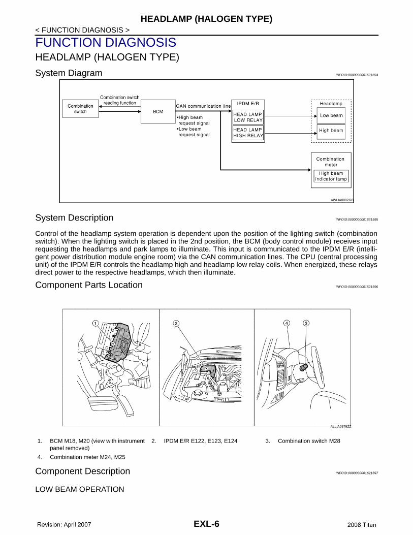
System Description INFOID:0000000001621595
Control of the headlamp system operation is dependent upon the position of the lighting switch (combinationswitch). When the lighting switch is placed in the 2nd position, the BCM (body control module) receives inputrequesting the headlamps and park lamps to illuminate. This input is communicated to the IPDM E/R (intelli-gent power distribution module engine room) via the CAN communication lines. The CPU (central processingunit) of the IPDM E/R controls the headlamp high and headlamp low relay coils. When energized, these relaysdirect power to the respective headlamps, which then illuminate.
Component Parts Location INFOID:0000000001621596
Component Description INFOID:0000000001621597
LOW BEAM OPERATION
AWLIA0002GB
1. BCM M18, M20 (view with instrument panel removed)
2. IPDM E/R E122, E123, E124 3. Combination switch M28
4. Combination meter M24, M25
ALLIA0379ZZ
EXL-6
HEADLAMP (HALOGEN TYPE)
C
D
E
F
G
H
I
J
K
M
A
B
XL
N
O
P
< FUNCTION DIAGNOSIS >
E
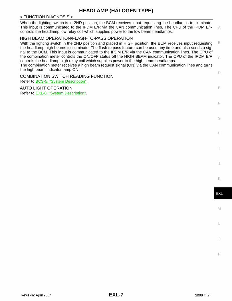
When the lighting switch is in 2ND position, the BCM receives input requesting the headlamps to illuminate.This input is communicated to the IPDM E/R via the CAN communication lines. The CPU of the IPDM E/Rcontrols the headlamp low relay coil which supplies power to the low beam headlamps.
HIGH BEAM OPERATION/FLASH-TO-PASS OPERATIONWith the lighting switch in the 2ND position and placed in HIGH position, the BCM receives input requestingthe headlamp high beams to illuminate. The flash to pass feature can be used any time and also sends a sig-nal to the BCM. This input is communicated to the IPDM E/R via the CAN communication lines. The CPU ofthe combination meter controls the ON/OFF status off the HIGH BEAM indicator. The CPU of the IPDM E/Rcontrols the headlamp high relay coil which supplies power to the high beam headlamps.The combination meter receives a high beam request signal (ON) via the CAN communication lines and turnsthe high beam indicator lamp ON.
COMBINATION SWITCH READING FUNCTIONRefer to BCS-5, "System Description".
AUTO LIGHT OPERATIONRefer to EXL-8, "System Description".
EXL-7
AUTO LIGHT SYSTEM
< FUNCTION DIAGNOSIS >AUTO LIGHT SYSTEM
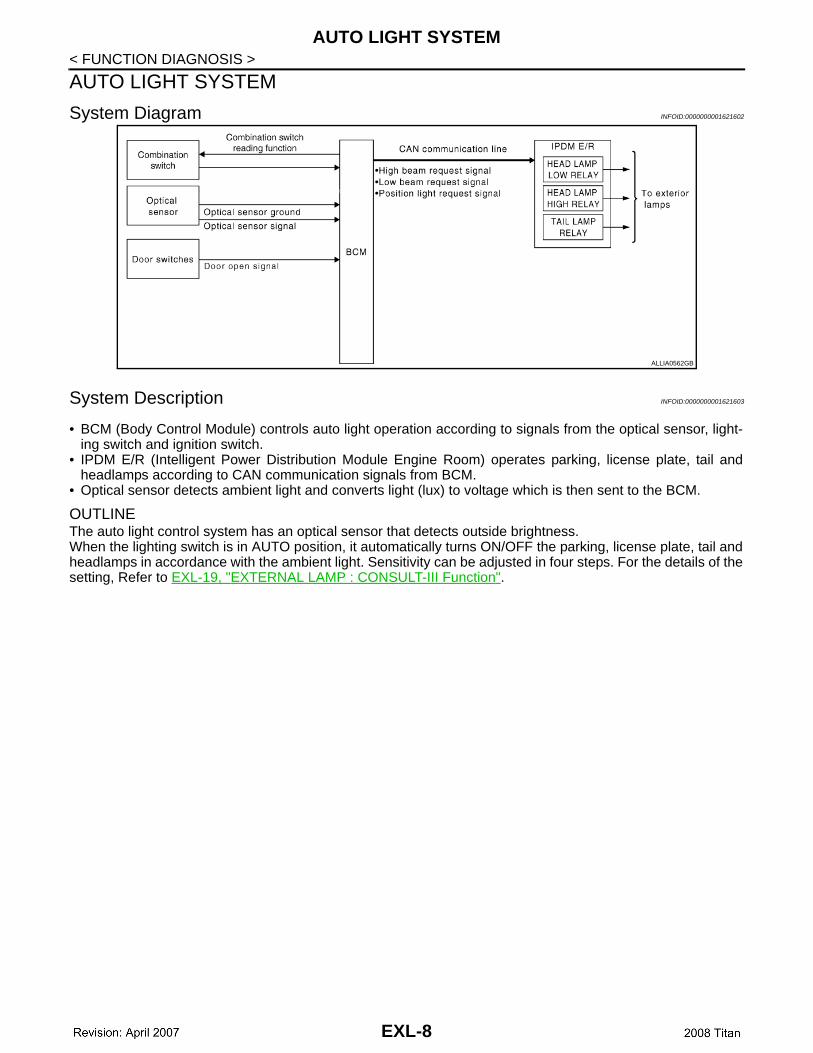
System Diagram INFOID:0000000001621602
System Description INFOID:0000000001621603
• BCM (Body Control Module) controls auto light operation according to signals from the optical sensor, light-ing switch and ignition switch.
• IPDM E/R (Intelligent Power Distribution Module Engine Room) operates parking, license plate, tail andheadlamps according to CAN communication signals from BCM.
• Optical sensor detects ambient light and converts light (lux) to voltage which is then sent to the BCM.
OUTLINEThe auto light control system has an optical sensor that detects outside brightness.When the lighting switch is in AUTO position, it automatically turns ON/OFF the parking, license plate, tail andheadlamps in accordance with the ambient light. Sensitivity can be adjusted in four steps. For the details of thesetting, Refer to EXL-19, "EXTERNAL LAMP : CONSULT-III Function".
ALLIA0562GB
EXL-8
AUTO LIGHT SYSTEM
C
D
E
F
G
H
I
J
K
M
A
B
XL
N
O
P
< FUNCTION DIAGNOSIS >
E
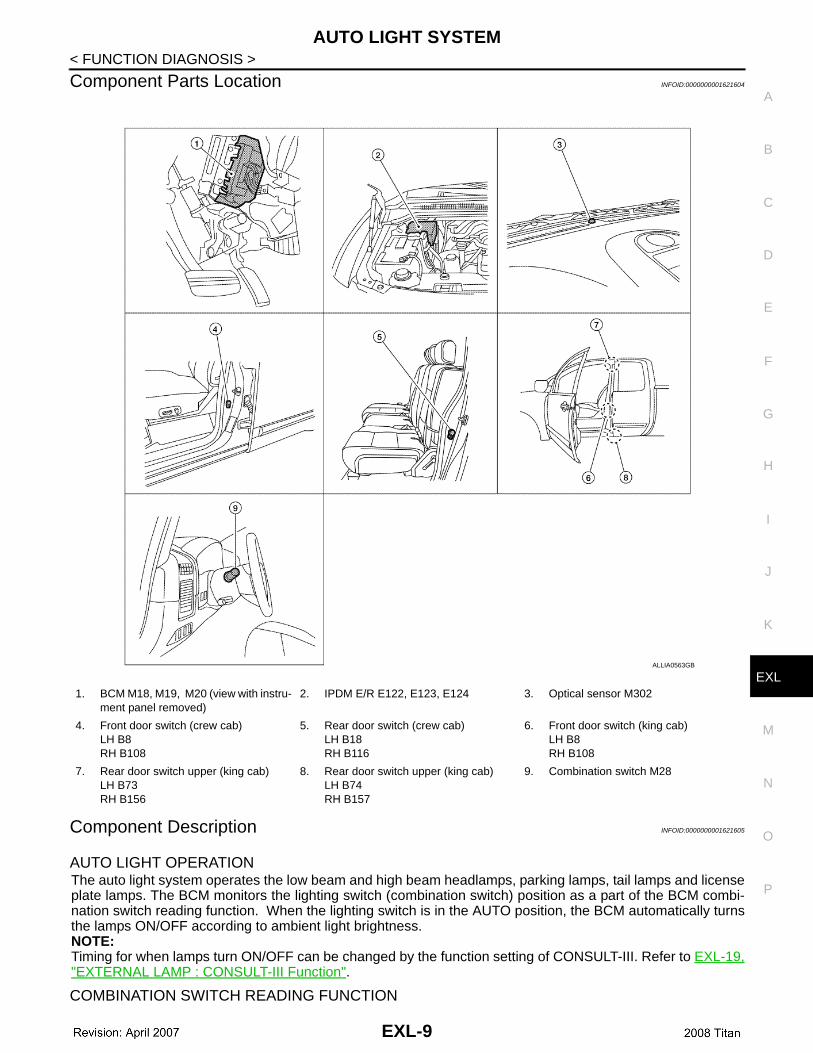
Component Parts Location INFOID:0000000001621604
Component Description INFOID:0000000001621605
AUTO LIGHT OPERATIONThe auto light system operates the low beam and high beam headlamps, parking lamps, tail lamps and licenseplate lamps. The BCM monitors the lighting switch (combination switch) position as a part of the BCM combi-nation switch reading function. When the lighting switch is in the AUTO position, the BCM automatically turnsthe lamps ON/OFF according to ambient light brightness. NOTE:Timing for when lamps turn ON/OFF can be changed by the function setting of CONSULT-III. Refer to EXL-19,"EXTERNAL LAMP : CONSULT-III Function".
COMBINATION SWITCH READING FUNCTION
1. BCM M18, M19, M20 (view with instru-ment panel removed)
2. IPDM E/R E122, E123, E124 3. Optical sensor M302
4. Front door switch (crew cab)LH B8RH B108
5. Rear door switch (crew cab)LH B18RH B116
6. Front door switch (king cab)LH B8RH B108
7. Rear door switch upper (king cab)LH B73RH B156
8. Rear door switch upper (king cab)LH B74RH B157
9. Combination switch M28
ALLIA0563GB
EXL-9
AUTO LIGHT SYSTEM
< FUNCTION DIAGNOSIS >Refer to BCS-7, "System Description".HEADLAMP LOW AND HIGH OPERATION Refer to EXL-6, "System Description".
PARKING, LICENSE PLATE AND TAIL LAMPS OPERATIONRefer to EXL-16, "System Description".
EXL-10
DAYTIME RUNNING LIGHT SYSTEM
C
D
E
F
G
H
I
J
K
M
A
B
XL
N
O
P
< FUNCTION DIAGNOSIS >
E
DAYTIME RUNNING LIGHT SYSTEM
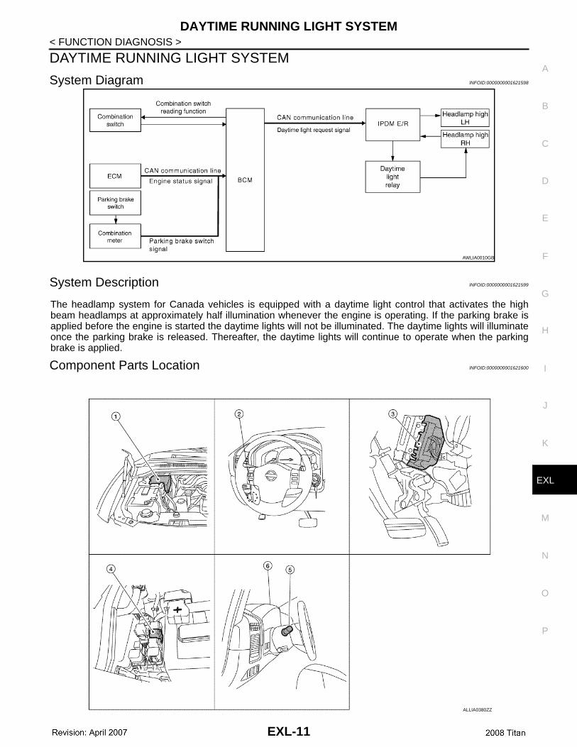
System Diagram INFOID:0000000001621598
System Description INFOID:0000000001621599
The headlamp system for Canada vehicles is equipped with a daytime light control that activates the highbeam headlamps at approximately half illumination whenever the engine is operating. If the parking brake isapplied before the engine is started the daytime lights will not be illuminated. The daytime lights will illuminateonce the parking brake is released. Thereafter, the daytime lights will continue to operate when the parkingbrake is applied.
Component Parts Location INFOID:0000000001621600
AWLIA0010GB
ALLIA0380ZZ
EXL-11
DAYTIME RUNNING LIGHT SYSTEM
< FUNCTION DIAGNOSIS >Component Description INFOID:0000000001621601
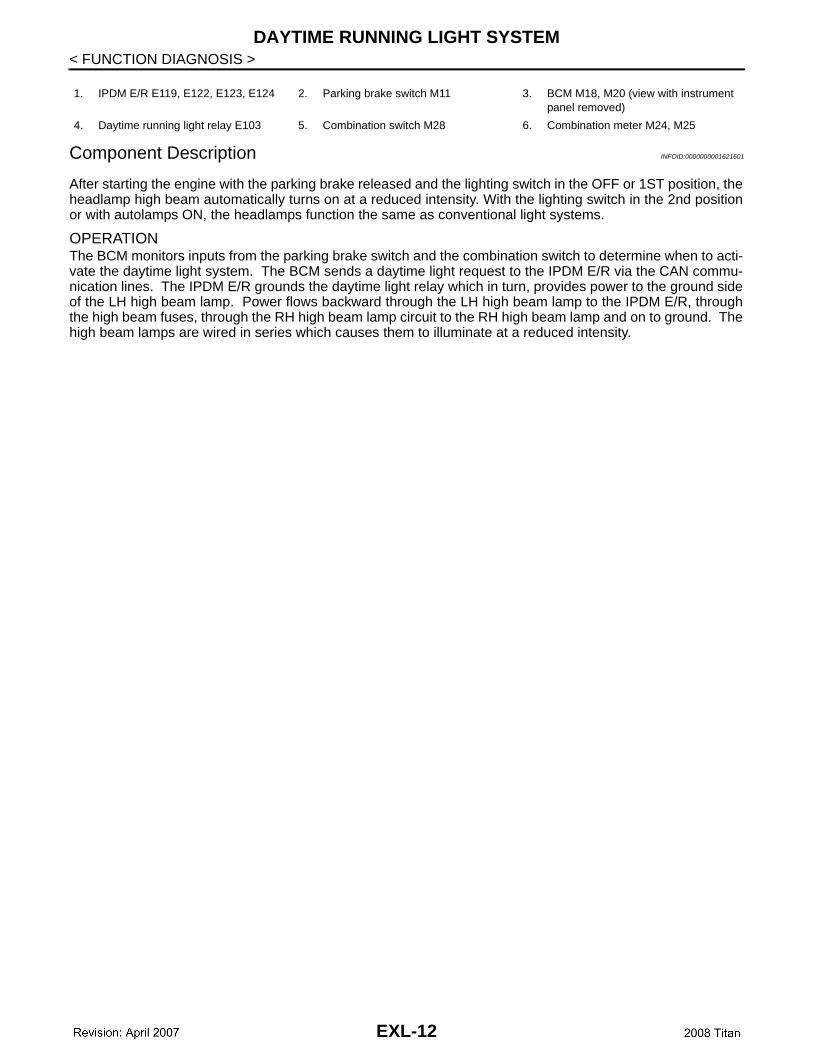
After starting the engine with the parking brake released and the lighting switch in the OFF or 1ST position, theheadlamp high beam automatically turns on at a reduced intensity. With the lighting switch in the 2nd positionor with autolamps ON, the headlamps function the same as conventional light systems.
OPERATIONThe BCM monitors inputs from the parking brake switch and the combination switch to determine when to acti-vate the daytime light system. The BCM sends a daytime light request to the IPDM E/R via the CAN commu-nication lines. The IPDM E/R grounds the daytime light relay which in turn, provides power to the ground sideof the LH high beam lamp. Power flows backward through the LH high beam lamp to the IPDM E/R, throughthe high beam fuses, through the RH high beam lamp circuit to the RH high beam lamp and on to ground. Thehigh beam lamps are wired in series which causes them to illuminate at a reduced intensity.
1. IPDM E/R E119, E122, E123, E124 2. Parking brake switch M11 3. BCM M18, M20 (view with instrument panel removed)
4. Daytime running light relay E103 5. Combination switch M28 6. Combination meter M24, M25
EXL-12
FRONT FOG LAMP
C
D
E
F
G
H
I
J
K
M
A
B
XL
N
O
P
< FUNCTION DIAGNOSIS >
E
FRONT FOG LAMP
System Diagram INFOID:0000000001621606
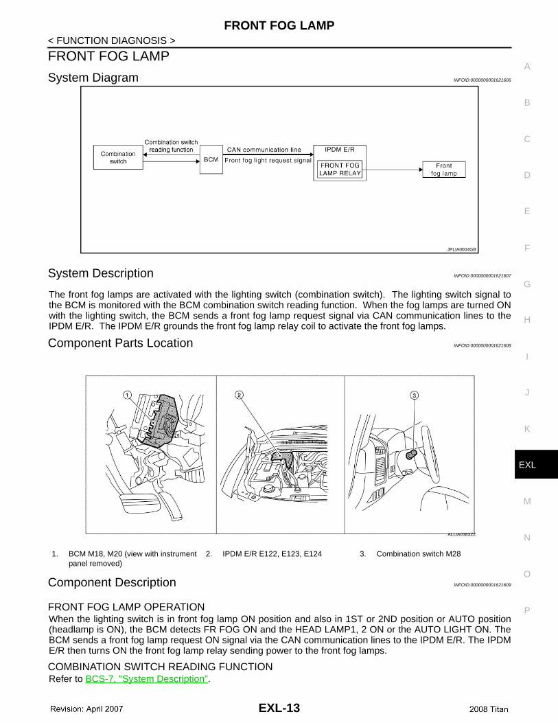
System Description INFOID:0000000001621607
The front fog lamps are activated with the lighting switch (combination switch). The lighting switch signal tothe BCM is monitored with the BCM combination switch reading function. When the fog lamps are turned ONwith the lighting switch, the BCM sends a front fog lamp request signal via CAN communication lines to theIPDM E/R. The IPDM E/R grounds the front fog lamp relay coil to activate the front fog lamps.
Component Parts Location INFOID:0000000001621608
Component Description INFOID:0000000001621609
FRONT FOG LAMP OPERATIONWhen the lighting switch is in front fog lamp ON position and also in 1ST or 2ND position or AUTO position(headlamp is ON), the BCM detects FR FOG ON and the HEAD LAMP1, 2 ON or the AUTO LIGHT ON. TheBCM sends a front fog lamp request ON signal via the CAN communication lines to the IPDM E/R. The IPDME/R then turns ON the front fog lamp relay sending power to the front fog lamps.
COMBINATION SWITCH READING FUNCTIONRefer to BCS-7, "System Description".
JPLIA0004GB
1. BCM M18, M20 (view with instrument panel removed)
2. IPDM E/R E122, E123, E124 3. Combination switch M28
ALLIA0383ZZ
EXL-13

TURN SIGNAL AND HAZARD WARNING LAMPS
< FUNCTION DIAGNOSIS >TURN SIGNAL AND HAZARD WARNING LAMPS
System Diagram INFOID:0000000001621610
System Description INFOID:0000000001621611
TURN SIGNAL OPERATIONWhen the turn signal switch is in LH or RH position with the ignition switch in ON position, the BCM detects theTURN RH or TURN LH ON request. The BCM outputs the flasher signal to the respective turn signal lamp.The BCM also sends a turn indicator signal ON request via the CAN communication lines to the combinationmeter. The combination meter then activates the appropriate turn signal indicator and audible buzzer.
HAZARD LAMP OPERATIONWhen the hazard switch is in ON position, the BCM detects the hazard switch signal ON. The BCM outputs theflasher signal (right and left). The BCM sends a hazard indicator signal ON request via the CAN communica-tion lines to the combination meter. The combination meter then activates the hazard indicator and audiblebuzzer.
REMOTE KEYLESS ENTRY OPERATIONThe remote keyless entry receiver transmits a hazard request signal to the BCM, then BCM controls hazardlamps.Refer to DLK-10, "REMOTE KEYLESS ENTRY : System Description".
COMBINATION SWITCH READING FUNCTIONRefer to BCS-7, "System Description".
AWLIA0006GB
EXL-14
TURN SIGNAL AND HAZARD WARNING LAMPS
C
D
E
F
G
H
I
J
K
M
A
B
XL
N
O
P
< FUNCTION DIAGNOSIS >
E
Component Parts Location INFOID:0000000001621612
Component Description INFOID:0000000001621613
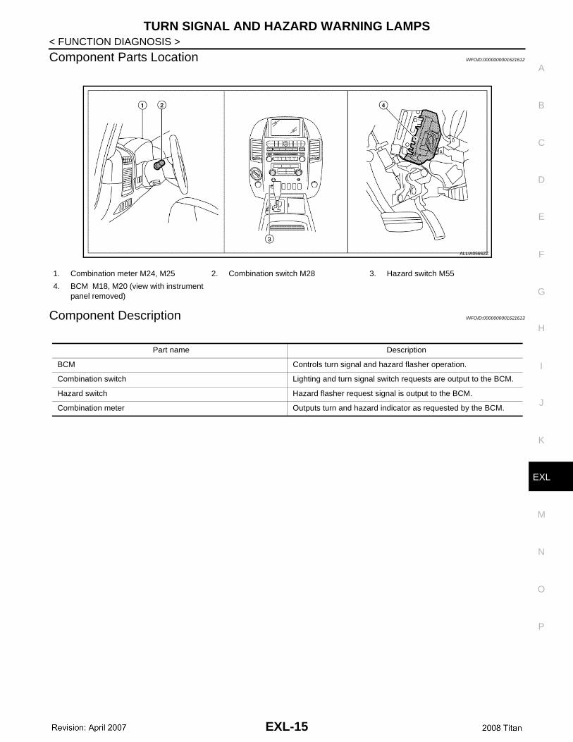
1. Combination meter M24, M25 2. Combination switch M28 3. Hazard switch M55
4. BCM M18, M20 (view with instrument panel removed)
ALLIA0566ZZ
Part name Description
BCM Controls turn signal and hazard flasher operation.
Combination switch Lighting and turn signal switch requests are output to the BCM.
Hazard switch Hazard flasher request signal is output to the BCM.
Combination meter Outputs turn and hazard indicator as requested by the BCM.
EXL-15
PARKING, LICENSE PLATE AND TAIL LAMPS
< FUNCTION DIAGNOSIS >PARKING, LICENSE PLATE AND TAIL LAMPS
System Diagram INFOID:0000000001621614
System Description INFOID:0000000001621615
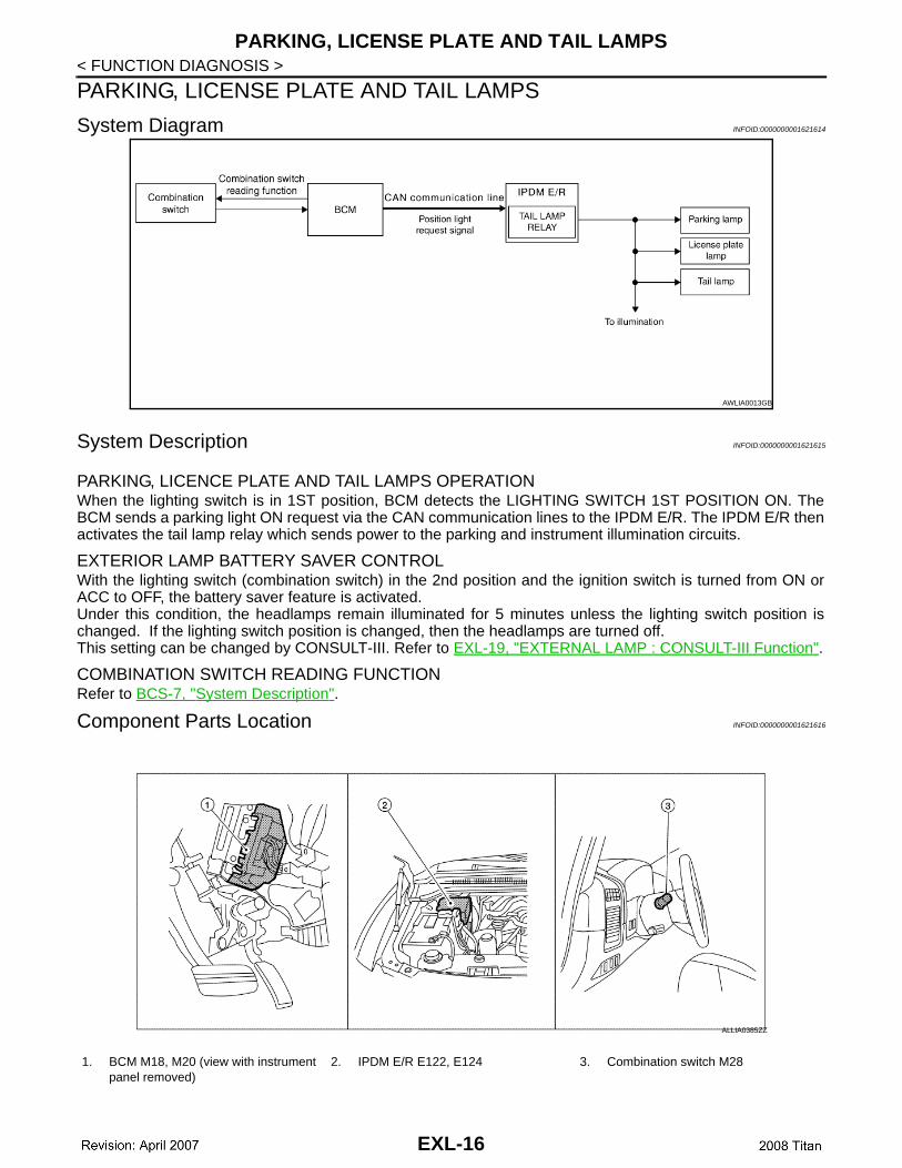
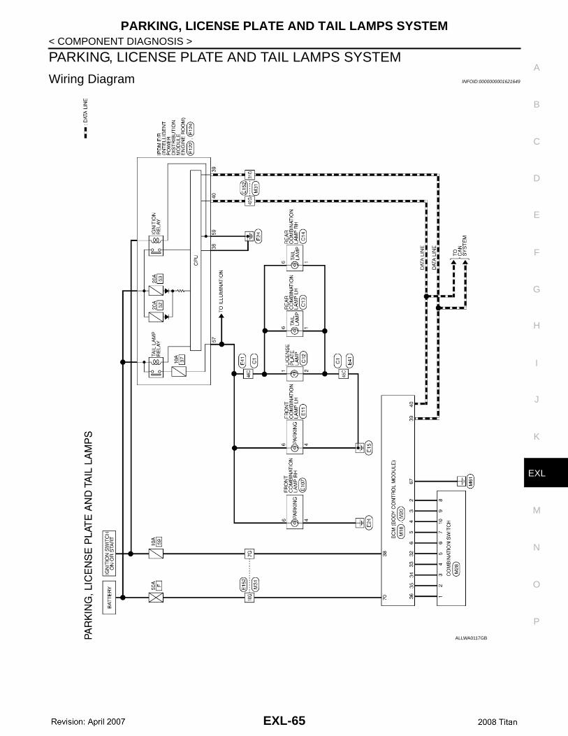
PARKING, LICENCE PLATE AND TAIL LAMPS OPERATIONWhen the lighting switch is in 1ST position, BCM detects the LIGHTING SWITCH 1ST POSITION ON. TheBCM sends a parking light ON request via the CAN communication lines to the IPDM E/R. The IPDM E/R thenactivates the tail lamp relay which sends power to the parking and instrument illumination circuits.
EXTERIOR LAMP BATTERY SAVER CONTROLWith the lighting switch (combination switch) in the 2nd position and the ignition switch is turned from ON orACC to OFF, the battery saver feature is activated.Under this condition, the headlamps remain illuminated for 5 minutes unless the lighting switch position ischanged. If the lighting switch position is changed, then the headlamps are turned off. This setting can be changed by CONSULT-III. Refer to EXL-19, "EXTERNAL LAMP : CONSULT-III Function".
COMBINATION SWITCH READING FUNCTIONRefer to BCS-7, "System Description".
Component Parts Location INFOID:0000000001621616
AWLIA0013GB
1. BCM M18, M20 (view with instrument panel removed)
2. IPDM E/R E122, E124 3. Combination switch M28
ALLIA0385ZZ
EXL-16
PARKING, LICENSE PLATE AND TAIL LAMPS
C
D
E
F
G
H
I
J
K
M
A
B
XL
N
O
P
< FUNCTION DIAGNOSIS >
E
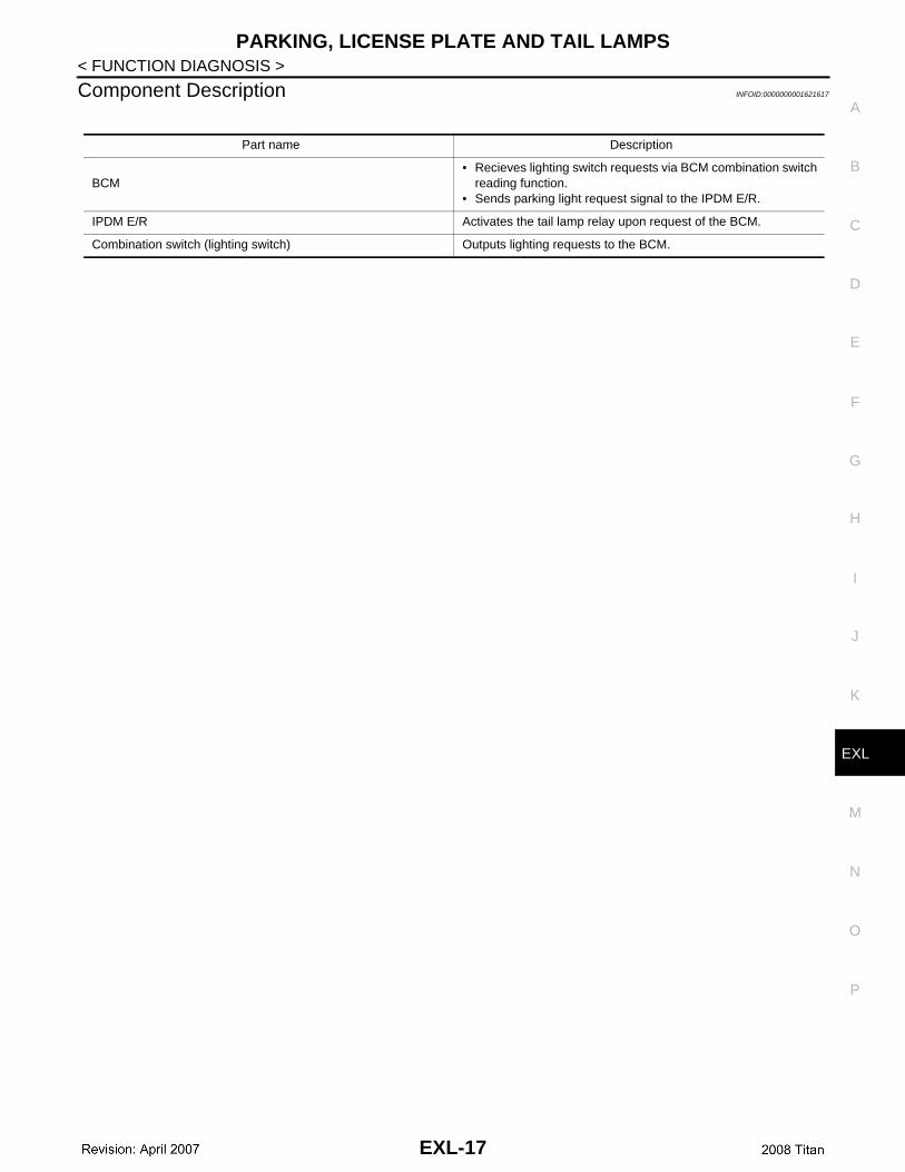
Component Description INFOID:0000000001621617
Part name Description
BCM• Recieves lighting switch requests via BCM combination switch
reading function.• Sends parking light request signal to the IPDM E/R.
IPDM E/R Activates the tail lamp relay upon request of the BCM.
Combination switch (lighting switch) Outputs lighting requests to the BCM.
EXL-17
COMBINATION SWITCH
< FUNCTION DIAGNOSIS >COMBINATION SWITCH
System Description INFOID:0000000001621618
For information regarding the combination switch, refer to EXL-18, "System Description"
EXL-18
DIAGNOSIS SYSTEM (BCM)
C
D
E
F
G
H
I
J
K
M
A
B
XL
N
O
P
< FUNCTION DIAGNOSIS >
E
DIAGNOSIS SYSTEM (BCM)COMMON ITEM
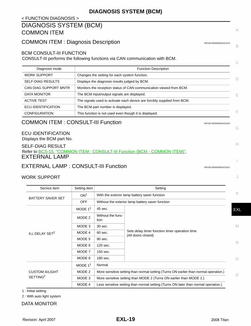
COMMON ITEM : Diagnosis Description INFOID:0000000001621619
BCM CONSULT-III FUNCTIONCONSULT-III performs the following functions via CAN communication with BCM.
COMMON ITEM : CONSULT-III Function INFOID:0000000001621620
ECU IDENTIFICATIONDisplays the BCM part No.
SELF-DIAG RESULTRefer to BCS-15, "COMMON ITEM : CONSULT-III Function (BCM - COMMON ITEM)".EXTERNAL LAMP
EXTERNAL LAMP : CONSULT-III Function INFOID:0000000001621621
WORK SUPPORT
1 : Initial setting
2 : With auto light system
DATA MONITOR
Diagnosis mode Function Description
WORK SUPPORT Changes the setting for each system function.
SELF-DIAG RESULTS Displays the diagnosis results judged by BCM.
CAN DIAG SUPPORT MNTR Monitors the reception status of CAN communication viewed from BCM.
DATA MONITOR The BCM input/output signals are displayed.
ACTIVE TEST The signals used to activate each device are forcibly supplied from BCM.
ECU IDENTIFICATION The BCM part number is displayed.
CONFIGURATION This function is not used even though it is displayed.
Service item Setting item Setting
BATTERY SAVER SETON1 With the exterior lamp battery saver function
OFF Without the exterior lamp battery saver function
ILL DELAY SET2
MODE 11 45 sec.
Sets delay timer function timer operation time(All doors closed)
MODE 2Without the func-tion
MODE 3 30 sec.
MODE 4 60 sec.
MODE 5 90 sec.
MODE 6 120 sec.
MODE 7 150 sec.
MODE 8 180 sec.
CUSTOM A/LIGHT
SETTING2
MODE 11 Normal
MODE 2 More sensitive setting than normal setting (Turns ON earlier than normal operation.)
MODE 3 More sensitive setting than MODE 2 (Turns ON earlier than MODE 2.)
MODE 4 Less sensitive setting than normal setting (Turns ON later than normal operation.)
EXL-19
DIAGNOSIS SYSTEM (BCM)
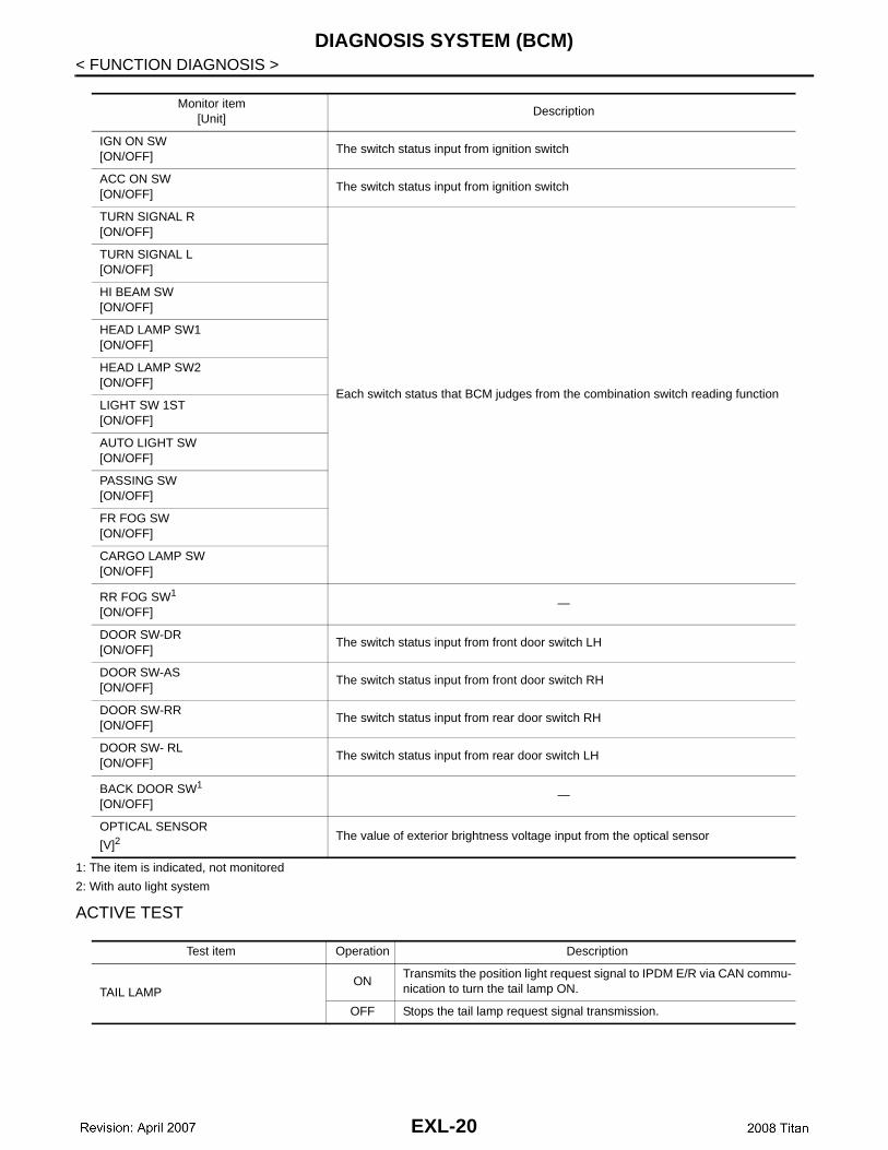
< FUNCTION DIAGNOSIS >1: The item is indicated, not monitored
2: With auto light system
ACTIVE TEST
Monitor item[Unit]
Description
IGN ON SW[ON/OFF]
The switch status input from ignition switch
ACC ON SW[ON/OFF]
The switch status input from ignition switch
TURN SIGNAL R[ON/OFF]
Each switch status that BCM judges from the combination switch reading function
TURN SIGNAL L[ON/OFF]
HI BEAM SW[ON/OFF]
HEAD LAMP SW1[ON/OFF]
HEAD LAMP SW2[ON/OFF]
LIGHT SW 1ST[ON/OFF]
AUTO LIGHT SW[ON/OFF]
PASSING SW[ON/OFF]
FR FOG SW[ON/OFF]
CARGO LAMP SW[ON/OFF]
RR FOG SW1
[ON/OFF]—
DOOR SW-DR[ON/OFF]
The switch status input from front door switch LH
DOOR SW-AS[ON/OFF]
The switch status input from front door switch RH
DOOR SW-RR[ON/OFF]
The switch status input from rear door switch RH
DOOR SW- RL[ON/OFF]
The switch status input from rear door switch LH
BACK DOOR SW1
[ON/OFF]—
OPTICAL SENSOR
[V]2The value of exterior brightness voltage input from the optical sensor
Test item Operation Description
TAIL LAMPON
Transmits the position light request signal to IPDM E/R via CAN commu-nication to turn the tail lamp ON.
OFF Stops the tail lamp request signal transmission.
EXL-20
DIAGNOSIS SYSTEM (BCM)
C
D
E
F
G
H
I
J
K
M
A
B
XL
N
O
P
< FUNCTION DIAGNOSIS >
E
1: The item is indicated, not monitored.
FLASHER
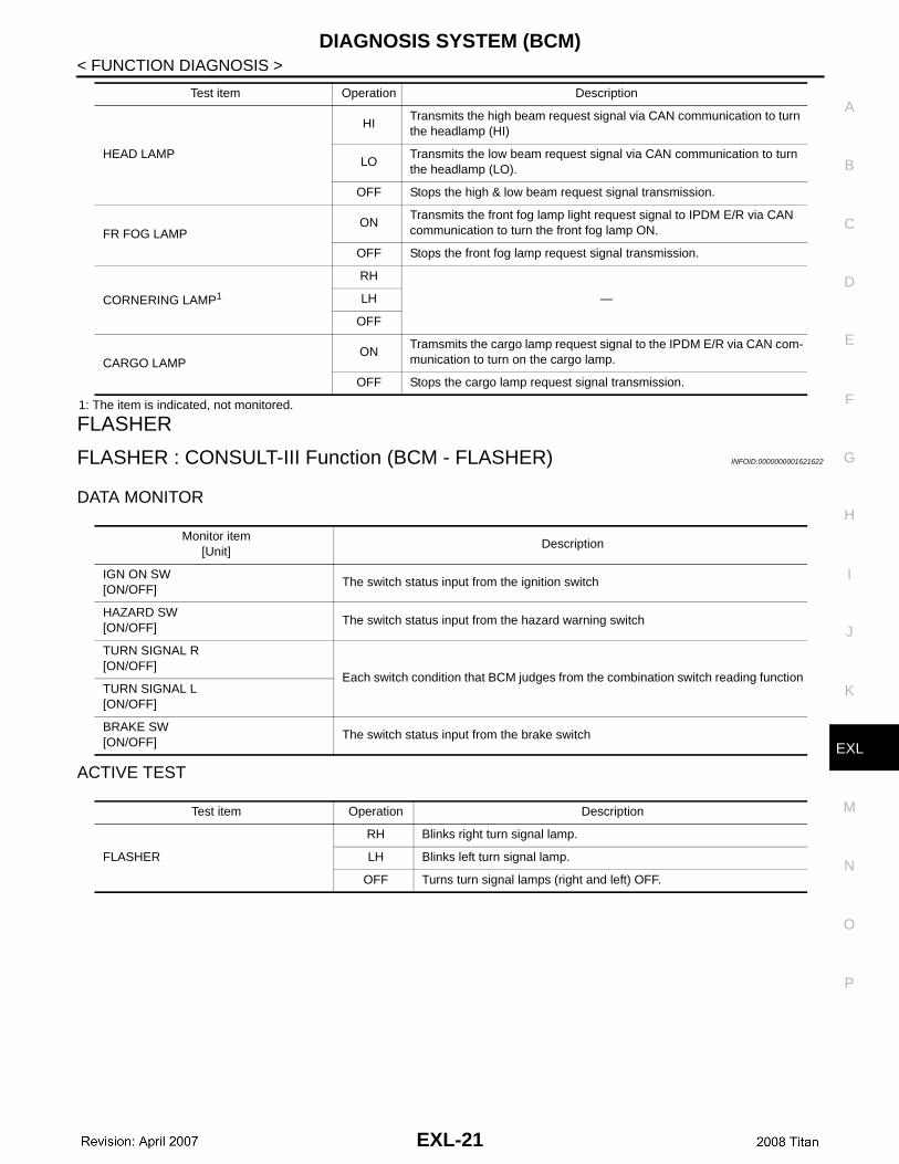
FLASHER : CONSULT-III Function (BCM - FLASHER) INFOID:0000000001621622
DATA MONITOR
ACTIVE TEST
HEAD LAMP
HITransmits the high beam request signal via CAN communication to turn the headlamp (HI)
LOTransmits the low beam request signal via CAN communication to turn the headlamp (LO).
OFF Stops the high & low beam request signal transmission.
FR FOG LAMPON
Transmits the front fog lamp light request signal to IPDM E/R via CAN communication to turn the front fog lamp ON.
OFF Stops the front fog lamp request signal transmission.
CORNERING LAMP1
RH
—LH
OFF
CARGO LAMPON
Tramsmits the cargo lamp request signal to the IPDM E/R via CAN com-munication to turn on the cargo lamp.
OFF Stops the cargo lamp request signal transmission.
Test item Operation Description
Monitor item[Unit]
Description
IGN ON SW[ON/OFF]
The switch status input from the ignition switch
HAZARD SW[ON/OFF]
The switch status input from the hazard warning switch
TURN SIGNAL R [ON/OFF]
Each switch condition that BCM judges from the combination switch reading functionTURN SIGNAL L [ON/OFF]
BRAKE SW[ON/OFF]
The switch status input from the brake switch
Test item Operation Description
FLASHER
RH Blinks right turn signal lamp.
LH Blinks left turn signal lamp.
OFF Turns turn signal lamps (right and left) OFF.
EXL-21
DIAGNOSIS SYSTEM (IPDM E/R)
< FUNCTION DIAGNOSIS >DIAGNOSIS SYSTEM (IPDM E/R)
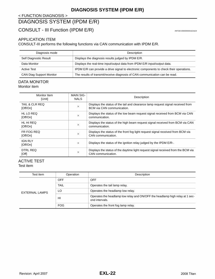
CONSULT - III Function (IPDM E/R) INFOID:0000000001621623
APPLICATION ITEMCONSULT-III performs the following functions via CAN communication with IPDM E/R.
DATA MONITORMonitor item
ACTIVE TESTTest item
Diagnosis mode Description
Self Diagnostic Result Displays the diagnosis results judged by IPDM E/R.
Data Monitor Displays the real-time input/output data from IPDM E/R input/output data.
Active Test IPDM E/R can provide a drive signal to electronic components to check their operations.
CAN Diag Support Monitor The results of transmit/receive diagnosis of CAN communication can be read.
Monitor Item[Unit]
MAIN SIG-NALS
Description
TAIL & CLR REQ[Off/On]
× Displays the status of the tail and clearance lamp request signal received from BCM via CAN communication.
HL LO REQ[Off/On]
× Displays the status of the low beam request signal received from BCM via CAN communication.
HL HI REQ[Off/On]
× Displays the status of the high beam request signal received from BCM via CAN communication.
FR FOG REQ[Off/On]
× Displays the status of the front fog light request signal received from BCM via CAN communication.
IGN RLY[Off/On]
× Displays the status of the ignition relay judged by the IPDM E/R-.
DTRL REQ[Off]
× Displays the status of the daytime light request signal received from the BCM via CAN communication.
Test item Operation Description
EXTERNAL LAMPS
OFF OFF
TAIL Operates the tail lamp relay.
LO Operates the headlamp low relay.
HIOperates the headlamp low relay and ON/OFF the headlamp high relay at 1 sec-ond intervals.
FOG Operates the front fog lamp relay.
EXL-22

POWER SUPPLY AND GROUND CIRCUIT
C
D
E
F
G
H
I
J
K
M
A
B
XL
N
O
P
< COMPONENT DIAGNOSIS >
E
COMPONENT DIAGNOSISPOWER SUPPLY AND GROUND CIRCUITBCM (BODY CONTROL MODULE)
BCM (BODY CONTROL MODULE) : Diagnosis Procedure INFOID:0000000001621624
For BCM power supply and ground circuit information, refer to PCS-37, "BCM : Diagnosis Procedure".IPDM E/R (INTELLIGENT POWER DISTRIBUTION MODULE ENGINE ROOM)
IPDM E/R (INTELLIGENT POWER DISTRIBUTION MODULE ENGINE ROOM) : Di-agnosis Procedure INFOID:0000000001621625
For IPDM E/R power supply and ground circuit information, refer to PCS-37, "IPDM E/R (INTELLIGENTPOWER DISTRIBUTION MODULE ENGINE ROOM) : Diagnosis Procedure" .
EXL-23
HEADLAMP (HI) CIRCUIT
< COMPONENT DIAGNOSIS >HEADLAMP (HI) CIRCUIT
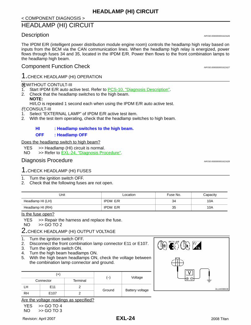
Description INFOID:0000000001621626
The IPDM E/R (intelligent power distribution module engine room) controls the headlamp high relay based oninputs from the BCM via the CAN communication lines. When the headlamp high relay is energized, powerflows through fuses 34 and 35, located in the IPDM E/R. Power then flows to the front combination lamps tothe headlamp high beam.
Component Function Check INFOID:0000000001621627
1.CHECK HEADLAMP (HI) OPERATION
WITHOUT CONTULT-III1. Start IPDM E/R auto active test. Refer to PCS-10, "Diagnosis Description".2. Check that the headlamp switches to the high beam.
NOTE:HI/LO is repeated 1 second each when using the IPDM E/R auto active test.
CONSULT-III1. Select "EXTERNAL LAMP" of IPDM E/R active test item.2. With the test item operating, check that the headlamp switches to high beam.
Does the headlamp switch to high beam?YES >> Headlamp (HI) circuit is normal.NO >> Refer to EXL-24, "Diagnosis Procedure".
Diagnosis Procedure INFOID:0000000001621628
1.CHECK HEADLAMP (HI) FUSES
1. Turn the ignition switch OFF.2. Check that the following fuses are not open.
Is the fuse open?YES >> Repair the harness and replace the fuse.NO >> GO TO 2
2.CHECK HEADLAMP (HI) OUTPUT VOLTAGE
1. Turn the ignition switch OFF.2. Disconnect the front combination lamp connector E11 or E107.3. Turn the ignition switch ON.4. Turn the high beam headlamps ON.5. With the high beam headlamps ON, check the voltage between
the combination lamp connector and ground.
Are the voltage readings as specified?YES >> GO TO 4NO >> GO TO 3
HI : Headlamp switches to the high beam.OFF : Headlamp OFF
Unit Location Fuse No. Capacity
Headlamp HI (LH) IPDM E/R 34 10A
Headlamp HI (RH) IPDM E/R 35 10A
(+)(−) Voltage
Connector Terminal
LH E11 2Ground Battery voltage
RH E107 2ALLIA0386GB
EXL-24

HEADLAMP (HI) CIRCUIT
C
D
E
F
G
H
I
J
K
M
A
B
XL
N
O
P
< COMPONENT DIAGNOSIS >
E
3.CHECK HEADLAMP (HI) CIRCUIT FOR OPEN
1. Turn the ignition switch OFF.2. Disconnect IPDM E/R connector E123.3. Check continuity between the IPDM E/R harness connector (A)
and the front combination lamp harness connector (B).
Does continuity exist?YES >> GO TO 4NO >> Repair the harnesses or connectors.
4.CHECK FRONT COMBINATION LAMP (HI) GROUND CIRCUIT
Check continuity between the front combination lamp harness con-nector terminal and ground.
Does continuity exist?YES >> Inspect the headlamp bulb.NO >> Repair the harness.
A BContinuity
Connector Terminal Connector Terminal
LHE123
55 E11 2Yes
RH 56 E107 2ALLIA0387GB
Connector Terminal — Continuity
LH E11 3Ground Yes
RH E107 3
ALLIA0388GB
EXL-25
HEADLAMP (LO) CIRCUIT
< COMPONENT DIAGNOSIS >HEADLAMP (LO) CIRCUIT
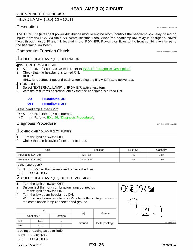
Description INFOID:0000000001621629
The IPDM E/R (intelligent power distribution module engine room) controls the headlamp low relay based oninputs from the BCM via the CAN communication lines. When the headlamp low relay is energized, powerflows through fuses 40 and 41, located in the IPDM E/R. Power then flows to the front combination lamps tothe headlamp low beam.
Component Function Check INFOID:0000000001621630
1.CHECK HEADLAMP (LO) OPERATION
WITHOUT CONSULT-III1. Start IPDM E/R auto active test. Refer to PCS-10, "Diagnosis Description".2. Check that the headlamp is turned ON.
NOTE:HI/LO is repeated 1 second each when using the IPDM E/R auto active test.
CONSULT-III1. Select "EXTERNAL LAMP" of IPDM E/R active test item.2. With the test items operating, check that the headlamp is turned ON.
Is the headlamp turned ON?YES >> Headlamp (LO) is normal.NO >> Refer to EXL-26, "Diagnosis Procedure".
Diagnosis Procedure INFOID:0000000001621631
1.CHECK HEADLAMP (LO) FUSES
1. Turn the ignition switch OFF.2. Check that the following fuses are not open.
Is the fuse open?YES >> Repair the harness and replace the fuse.NO >> GO TO 2
2.CHECK HEADLAMP (LO) OUTPUT VOLTAGE
1. Turn the ignition switch OFF.2. Disconnect the front combination lamp connector.3. Turn the ignition switch ON.4. Turn the low beam headlamps ON.5. With the low beam headlamps ON, check the voltage between
the combination lamp connector and ground.
Is voltage reading as specified?YES >> GO TO 4NO >> GO TO 3
LO : Headlamp ONOFF : Headlamp OFF
Unit Location Fuse No. Capacity
Headlamp LO (LH) IPDM E/R 40 15A
Headlamp LO (RH) IPDM E/R 41 15A
(+)(−) Voltage
Connector Terminal
LH E11 1Ground Battery voltage
RH E107 1ALLIA0389GB
EXL-26
HEADLAMP (LO) CIRCUIT
C
D
E
F
G
H
I
J
K
M
A
B
XL
N
O
P
< COMPONENT DIAGNOSIS >
E
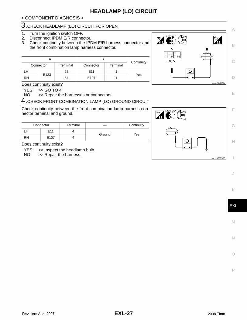
3.CHECK HEADLAMP (LO) CIRCUIT FOR OPEN
1. Turn the ignition switch OFF.2. Disconnect IPDM E/R connector.3. Check continuity between the IPDM E/R harness connector and
the front combination lamp harness connector.
Does continuity exist?YES >> GO TO 4NO >> Repair the harnesses or connectors.
4.CHECK FRONT COMBINATION LAMP (LO) GROUND CIRCUIT
Check continuity between the front combination lamp harness con-nector terminal and ground.
Does continuity exist?YES >> Inspect the headlamp bulb.NO >> Repair the harness.
A BContinuity
Connector Terminal Connector Terminal
LHE123
52 E11 1Yes
RH 54 E107 1ALLIA0390GB
Connector Terminal — Continuity
LH E11 4Ground Yes
RH E107 4
ALLIA0391GB
EXL-27
FRONT FOG LAMP CIRCUIT
< COMPONENT DIAGNOSIS >FRONT FOG LAMP CIRCUIT
Description INFOID:0000000001621632
The IPDM E/R (intelligent power distribution module engine room) controls the front fog lamp relay based oninputs from the BCM via the CAN communication lines. When the front fog lamp relay is energized, powerflows from the front fog lamp relay in the IPDM E/R to the front fog lamps.
Component Function Check INFOID:0000000001621633
1.CHECK FRONT FOG LAMP OPERATION
WITHOUT CONSULT-III1. Activate IPDM E/R auto active test. Refer to PCS-10, "Diagnosis Description".2. Check that the front fog lamp is turned ON.
CONSULT-III1. Select "EXTERNAL LAMP" of IPDM E/R active test item.2. With operating the test items, Check that the front fog lamp is turned ON.
Is the front fog lamp turned ON?YES >> Front fog lamp circuit is normal.NO >> Refer to EXL-28, "Diagnosis Procedure".
Diagnosis Procedure INFOID:0000000001621634
1.CHECK FRONT FOG LAMP FUSE
1. Turn the ignition switch OFF.2. Check that the following fuses are not open.
Is the fuse open?YES >> Repair the harness and replace the fuse.NO >> GO TO 2
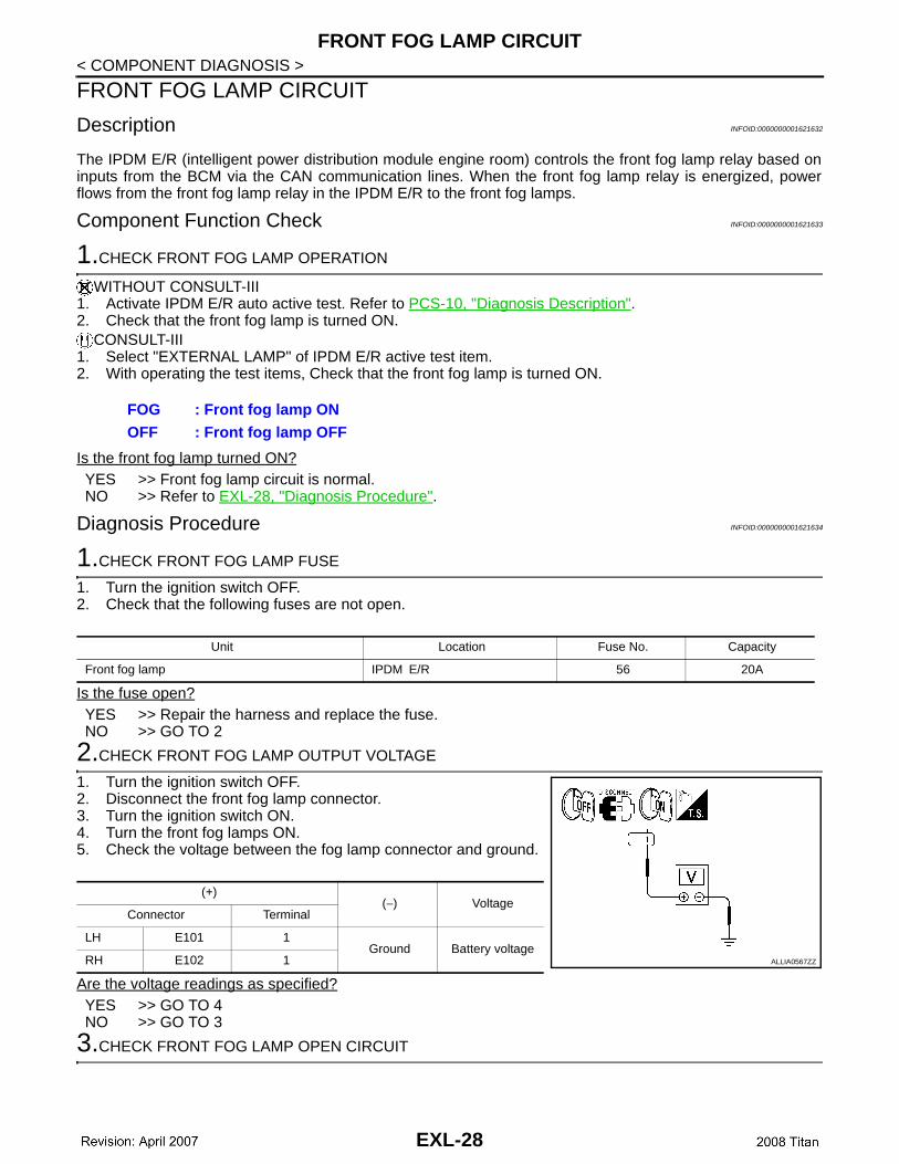
2.CHECK FRONT FOG LAMP OUTPUT VOLTAGE
1. Turn the ignition switch OFF.2. Disconnect the front fog lamp connector.3. Turn the ignition switch ON.4. Turn the front fog lamps ON.5. Check the voltage between the fog lamp connector and ground.
Are the voltage readings as specified?YES >> GO TO 4NO >> GO TO 3
3.CHECK FRONT FOG LAMP OPEN CIRCUIT
FOG : Front fog lamp ONOFF : Front fog lamp OFF
Unit Location Fuse No. Capacity
Front fog lamp IPDM E/R 56 20A
(+)(−) Voltage
Connector Terminal
LH E101 1Ground Battery voltage
RH E102 1 ALLIA0567ZZ
EXL-28
FRONT FOG LAMP CIRCUIT
C
D
E
F
G
H
I
J
K
M
A
B
XL
N
O
P
< COMPONENT DIAGNOSIS >
E
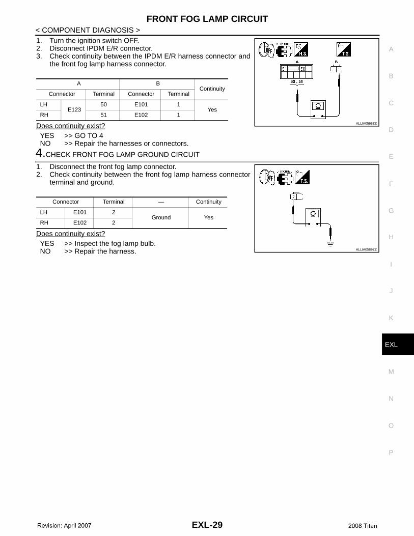
1. Turn the ignition switch OFF.2. Disconnect IPDM E/R connector.3. Check continuity between the IPDM E/R harness connector and
the front fog lamp harness connector.
Does continuity exist?YES >> GO TO 4 NO >> Repair the harnesses or connectors.
4.CHECK FRONT FOG LAMP GROUND CIRCUIT
1. Disconnect the front fog lamp connector.2. Check continuity between the front fog lamp harness connector
terminal and ground.
Does continuity exist?YES >> Inspect the fog lamp bulb.NO >> Repair the harness.
A BContinuity
Connector Terminal Connector Terminal
LHE123
50 E101 1Yes
RH 51 E102 1ALLIA0568ZZ
Connector Terminal — Continuity
LH E101 2Ground Yes
RH E102 2
ALLIA0569ZZ
EXL-29
PARKING LAMP CIRCUIT
< COMPONENT DIAGNOSIS >PARKING LAMP CIRCUIT
Description INFOID:0000000001621635
The IPDM E/R (intelligent power distribution module engine room) controls the tail lamp relay based on inputsfrom the BCM via the CAN communication lines. When the tail lamp relay is energized, power flows throughfuse 37, located in the IPDM E/R. Power then flows to the front and rear combination lamps.
Component Function Check INFOID:0000000001621636
1.CHECK PARKING LAMP OPERATION
WITHOUT CONSULT-III1. Activate IPDM E/R auto active test. Refer to PCS-10, "Diagnosis Description".2. Check that the parking lamp is turned ON.
CONSULT-III 1. Select "EXTERNAL LAMP" of IPDM E/R active test item.2. While operating the test item, check that the parking lamp is turned ON.
Is the parking lamp turned ON?YES >> Parking lamp circuit is normal.NO >> Refer to EXL-30, "Diagnosis Procedure".
Diagnosis Procedure INFOID:0000000001621637
1.CHECK PARKING LAMP FUSES
1. Turn the ignition switch OFF.2. Check that the following fuses are not open.
Is the fuse open?YES >> Repair the harness and replace the fuse.NO >> GO TO 2
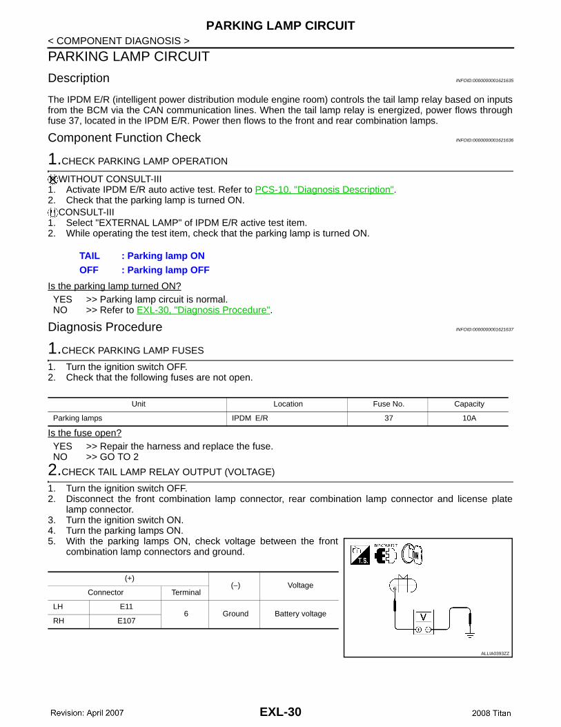
2.CHECK TAIL LAMP RELAY OUTPUT (VOLTAGE)
1. Turn the ignition switch OFF.2. Disconnect the front combination lamp connector, rear combination lamp connector and license plate
lamp connector.3. Turn the ignition switch ON.4. Turn the parking lamps ON.5. With the parking lamps ON, check voltage between the front
combination lamp connectors and ground.
TAIL : Parking lamp ONOFF : Parking lamp OFF
Unit Location Fuse No. Capacity
Parking lamps IPDM E/R 37 10A
(+)(−) Voltage
Connector Terminal
LH E116 Ground Battery voltage
RH E107
ALLIA0393ZZ
EXL-30

PARKING LAMP CIRCUIT
C
D
E
F
G
H
I
J
K
M
A
B
XL
N
O
P
< COMPONENT DIAGNOSIS >
E
6. With the parking lamps ON, check voltage between the rearcombination lamp connectors and ground.
7. With the parking lamps ON, check voltage between the licenseplate lamp connector and ground
Are voltage readings as specified?YES >> GO TO 4NO >> GO TO 3
3.CHECK PARKING, LICENSE PLATE AND TAIL LAMP CIRCUIT (OPEN)
1. Turn the ignition switch OFF.2. Disconnect IPDM E/R connector.3. Check continuity between the IPDM E/R harness connector (A)
and the front combination lamp harness connector (B).
4. Check continuity between the IPDM E/R harness connector (A)and the rear combination lamp harness connector (B).
(+)(−) Voltage
Connector Terminal
LH C136 Ground Battery voltage
RH C14
ALLIA0570ZZ
(+)(−) Voltage
Connector Terminal
C12 1 Ground Battery voltage
ALLIA0571ZZ
A BContinuity
Connector Terminal Connector Terminal
LHE124 57
E116 Yes
RH E107
ALLIA0396ZZ
A BContinuity
Connector Terminal Connector Terminal
LHE124 57
C136 Yes
RH C14
ALLIA0572ZZ
EXL-31
PARKING LAMP CIRCUIT
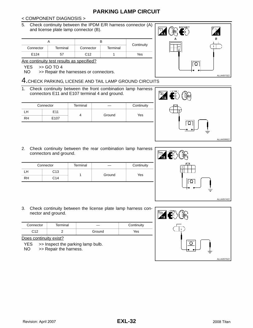
< COMPONENT DIAGNOSIS >5. Check continuity between the IPDM E/R harness connector (A)and license plate lamp connector (B).
Are continuity test results as specified?YES >> GO TO 4NO >> Repair the harnesses or connectors.
4.CHECK PARKING, LICENSE AND TAIL LAMP GROUND CIRCUITS
1. Check continuity between the front combination lamp harnessconnectors E11 and E107 terminal 4 and ground.
2. Check continuity between the rear combination lamp harnessconnectors and ground.
3. Check continuity between the license plate lamp harness con-nector and ground.
Does continuity exist?YES >> Inspect the parking lamp bulb.NO >> Repair the harness.
A BContinuity
Connector Terminal Connector Terminal
E124 57 C12 1 Yes
ALLIA0573ZZ
Connector Terminal — Continuity
LH E114 Ground Yes
RH E107
ALLIA0399ZZ
Connector Terminal — Continuity
LH C131 Ground Yes
RH C14
ALLIA0574ZZ
Connector Terminal — Continuity
C12 2 Ground Yes
ALLIA0575ZZ
EXL-32
TURN SIGNAL LAMP CIRCUIT
C
D
E
F
G
H
I
J
K
M
A
B
XL
N
O
P
< COMPONENT DIAGNOSIS >
E
TURN SIGNAL LAMP CIRCUIT
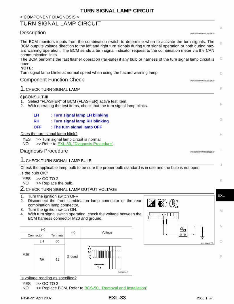
Description INFOID:0000000001621638
The BCM monitors inputs from the combination switch to determine when to activate the turn signals. TheBCM outputs voltage direction to the left and right turn signals during turn signal operation or both during haz-ard warning operation. The BCM sends a turn signal indicator request to the combination meter via the CANcommunication lines. The BCM performs the fast flasher operation (fail-safe) if any bulb or harness of the turn signal lamp circuit isopen.NOTE:Turn signal lamp blinks at normal speed when using the hazard warning lamp.
Component Function Check INFOID:0000000001621639
1.CHECK TURN SIGNAL LAMP
CONSULT-III1. Select "FLASHER" of BCM (FLASHER) active test item.2. With operating the test items, check that the turn signal lamp blinks.
Does the turn signal lamp blink?YES >> Turn signal lamp circuit is normal.NO >> Refer to EXL-33, "Diagnosis Procedure".
Diagnosis Procedure INFOID:0000000001621640
1.CHECK TURN SIGNAL LAMP BULB
Check the applicable lamp bulb to be sure the proper bulb standard is in use and the bulb is not open.Is the bulb OK?YES >> GO TO 2NO >> Replace the bulb.
2.CHECK TURN SIGNAL LAMP OUTPUT VOLTAGE
1. Turn the ignition switch OFF.2. Disconnect the front combination lamp connector or the rear
combination lamp connector.3. Turn the ignition switch ON.4. With turn signal switch operating, check the voltage between the
BCM harness connector M20 and ground.
Is voltage reading as specified?YES >> GO TO 3NO >> Replace BCM. Refer to BCS-50, "Removal and Installation"
LH : Turn signal lamp LH blinking RH : Turn signal lamp RH blinking OFF : The turn signal lamp OFF
(+)(−) Voltage
Connector Terminal
M20
LH 60
GroundRH 61
ALLIA0402ZZ
PKID0926E
EXL-33
TURN SIGNAL LAMP CIRCUIT
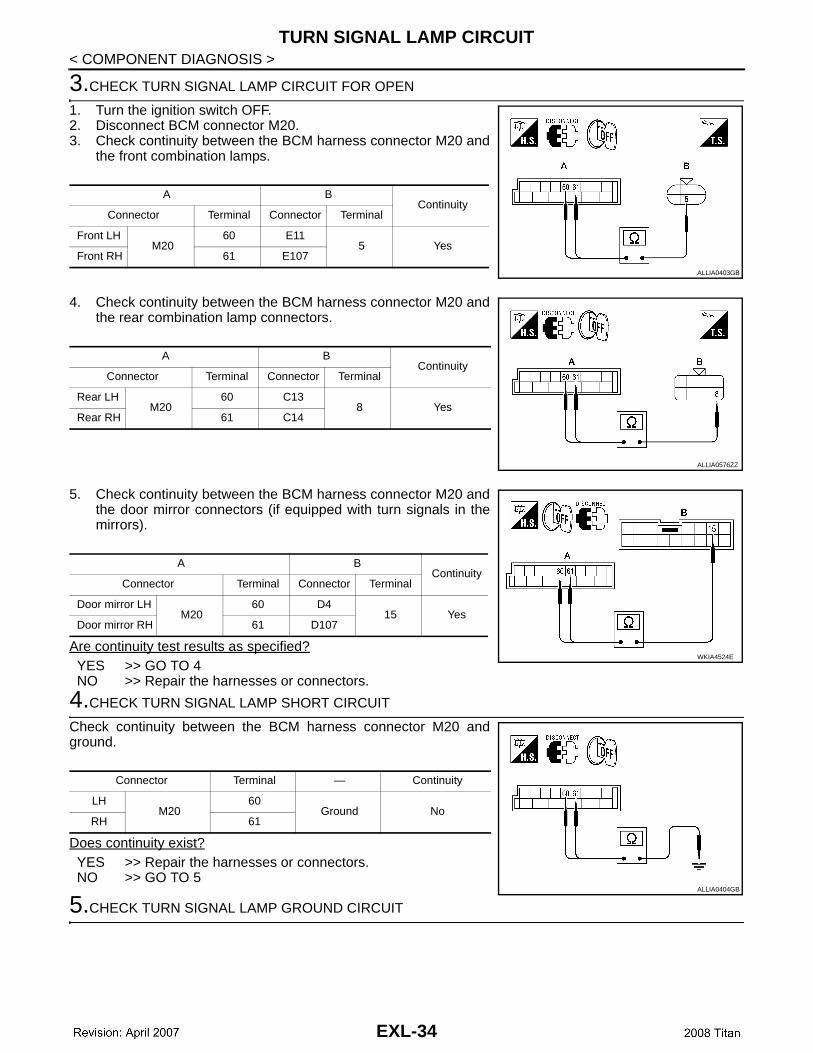
< COMPONENT DIAGNOSIS >3.CHECK TURN SIGNAL LAMP CIRCUIT FOR OPEN
1. Turn the ignition switch OFF.2. Disconnect BCM connector M20.3. Check continuity between the BCM harness connector M20 and
the front combination lamps.
4. Check continuity between the BCM harness connector M20 andthe rear combination lamp connectors.
5. Check continuity between the BCM harness connector M20 andthe door mirror connectors (if equipped with turn signals in themirrors).
Are continuity test results as specified?YES >> GO TO 4NO >> Repair the harnesses or connectors.
4.CHECK TURN SIGNAL LAMP SHORT CIRCUIT
Check continuity between the BCM harness connector M20 andground.
Does continuity exist?YES >> Repair the harnesses or connectors.NO >> GO TO 5
5.CHECK TURN SIGNAL LAMP GROUND CIRCUIT
A BContinuity
Connector Terminal Connector Terminal
Front LHM20
60 E115 Yes
Front RH 61 E107ALLIA0403GB
A BContinuity
Connector Terminal Connector Terminal
Rear LHM20
60 C138 Yes
Rear RH 61 C14
ALLIA0576ZZ
A BContinuity
Connector Terminal Connector Terminal
Door mirror LHM20
60 D415 Yes
Door mirror RH 61 D107
WKIA4524E
Connector Terminal — Continuity
LHM20
60Ground No
RH 61
ALLIA0404GB
EXL-34

TURN SIGNAL LAMP CIRCUIT
C
D
E
F
G
H
I
J
K
M
A
B
XL
N
O
P
< COMPONENT DIAGNOSIS >
E
1. Check continuity between the front combination lamp harnessconnectors and ground.
2. Check continuity between the rear combination lamp harnnessconnectors and ground.
3. Check continuity between the door mirrors and ground (ifequipped with turn signals in the mirrors).
Are continuity test results as specified?YES >> Replace the malfunctioning lamp.NO >> Repair the harnesses or connectors.
Connector Terminal — Continuity
Front LH E114 Ground Yes
Front RH E107
ALLIA0405GB
Connector Terminal — Continuity
Rear LH C131 Ground Yes
Rear RH C14
ALLIA0577ZZ
Connector Terminal — Continuity
Door mirror RH D10711 Ground Yes
Door mirror LH D4
WKIA4525E
EXL-35
OPTICAL SENSOR
< COMPONENT DIAGNOSIS >OPTICAL SENSOR
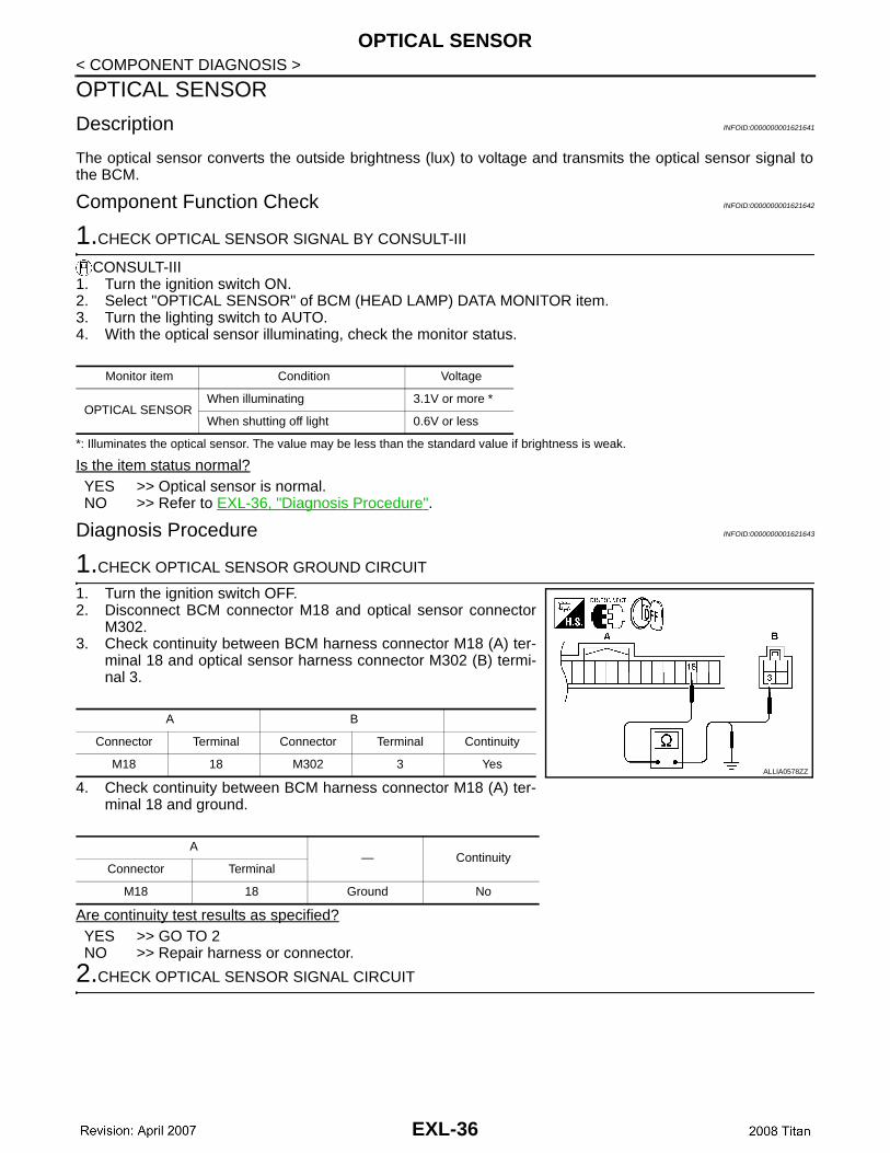
Description INFOID:0000000001621641
The optical sensor converts the outside brightness (lux) to voltage and transmits the optical sensor signal tothe BCM.
Component Function Check INFOID:0000000001621642
1.CHECK OPTICAL SENSOR SIGNAL BY CONSULT-III
CONSULT-III1. Turn the ignition switch ON.2. Select "OPTICAL SENSOR" of BCM (HEAD LAMP) DATA MONITOR item.3. Turn the lighting switch to AUTO.4. With the optical sensor illuminating, check the monitor status.
*: Illuminates the optical sensor. The value may be less than the standard value if brightness is weak.
Is the item status normal?YES >> Optical sensor is normal.NO >> Refer to EXL-36, "Diagnosis Procedure".
Diagnosis Procedure INFOID:0000000001621643
1.CHECK OPTICAL SENSOR GROUND CIRCUIT
1. Turn the ignition switch OFF.2. Disconnect BCM connector M18 and optical sensor connector
M302.3. Check continuity between BCM harness connector M18 (A) ter-
minal 18 and optical sensor harness connector M302 (B) termi-nal 3.
4. Check continuity between BCM harness connector M18 (A) ter-minal 18 and ground.
Are continuity test results as specified?YES >> GO TO 2NO >> Repair harness or connector.
2.CHECK OPTICAL SENSOR SIGNAL CIRCUIT
Monitor item Condition Voltage
OPTICAL SENSORWhen illuminating 3.1V or more *
When shutting off light 0.6V or less
A B
Connector Terminal Connector Terminal Continuity
M18 18 M302 3 Yes
A— Continuity
Connector Terminal
M18 18 Ground No
ALLIA0578ZZ
EXL-36
OPTICAL SENSOR
C
D
E
F
G
H
I
J
K
M
A
B
XL
N
O
P
< COMPONENT DIAGNOSIS >
E
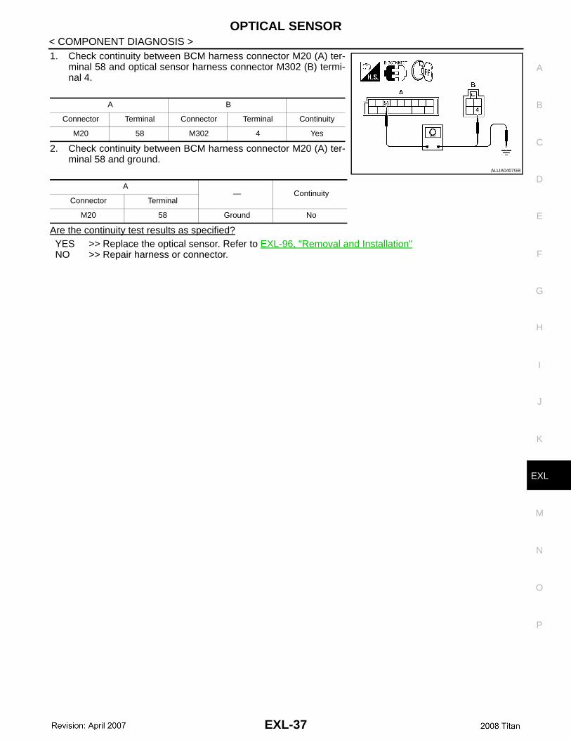
1. Check continuity between BCM harness connector M20 (A) ter-minal 58 and optical sensor harness connector M302 (B) termi-nal 4.
2. Check continuity between BCM harness connector M20 (A) ter-minal 58 and ground.
Are the continuity test results as specified?YES >> Replace the optical sensor. Refer to EXL-96, "Removal and Installation"NO >> Repair harness or connector.
A B
Connector Terminal Connector Terminal Continuity
M20 58 M302 4 Yes
A— Continuity
Connector Terminal
M20 58 Ground No
ALLIA0407GB
EXL-37
HEADLAMP
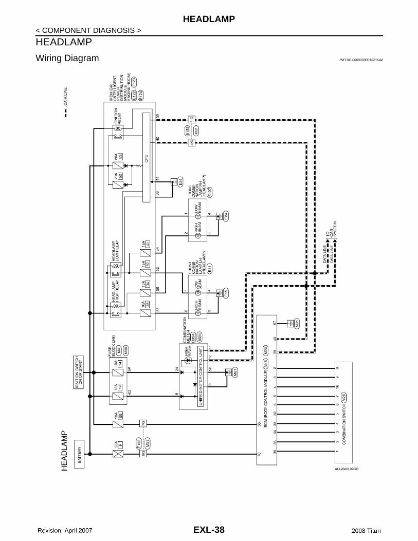
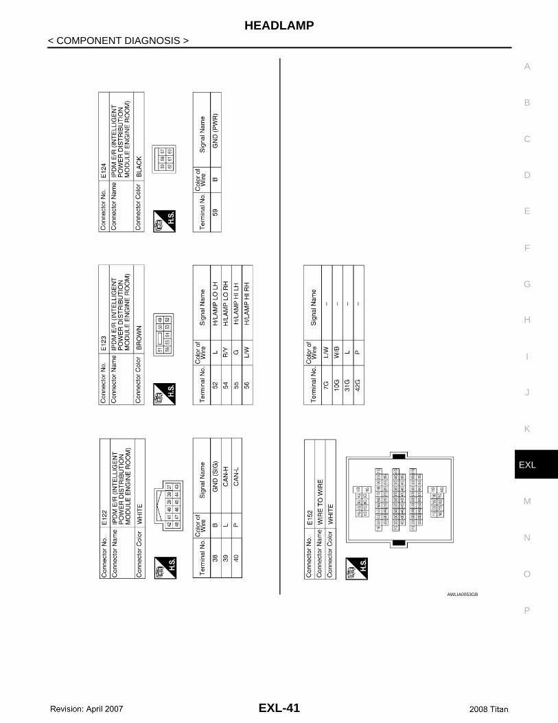
< COMPONENT DIAGNOSIS >HEADLAMP
Wiring Diagram INFOID:0000000001621644
ALLWA0109GB
EXL-38

HEADLAMP
C
D
E
F
G
H
I
J
K
M
A
B
XL
N
O
P
< COMPONENT DIAGNOSIS >
E
AWLIA0051GB
EXL-39

HEADLAMP
< COMPONENT DIAGNOSIS >AWLIA0052GB
EXL-40
HEADLAMP
C
D
E
F
G
H
I
J
K
M
A
B
XL
N
O
P
< COMPONENT DIAGNOSIS >
E
AWLIA0053GB
EXL-41

AUTO LIGHT SYSTEM
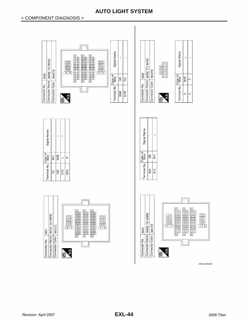
< COMPONENT DIAGNOSIS >AUTO LIGHT SYSTEM
Wiring Diagram INFOID:0000000001621646
ALLWA0110GB
EXL-42

AUTO LIGHT SYSTEM
C
D
E
F
G
H
I
J
K
M
A
B
XL
N
O
P
< COMPONENT DIAGNOSIS >
E
AWLIA0054GB
EXL-43
AUTO LIGHT SYSTEM
< COMPONENT DIAGNOSIS >AWLIA0055GB
EXL-44

AUTO LIGHT SYSTEM
C
D
E
F
G
H
I
J
K
M
A
B
XL
N
O
P
< COMPONENT DIAGNOSIS >
E
AWLIA0056GB
EXL-45
AUTO LIGHT SYSTEM
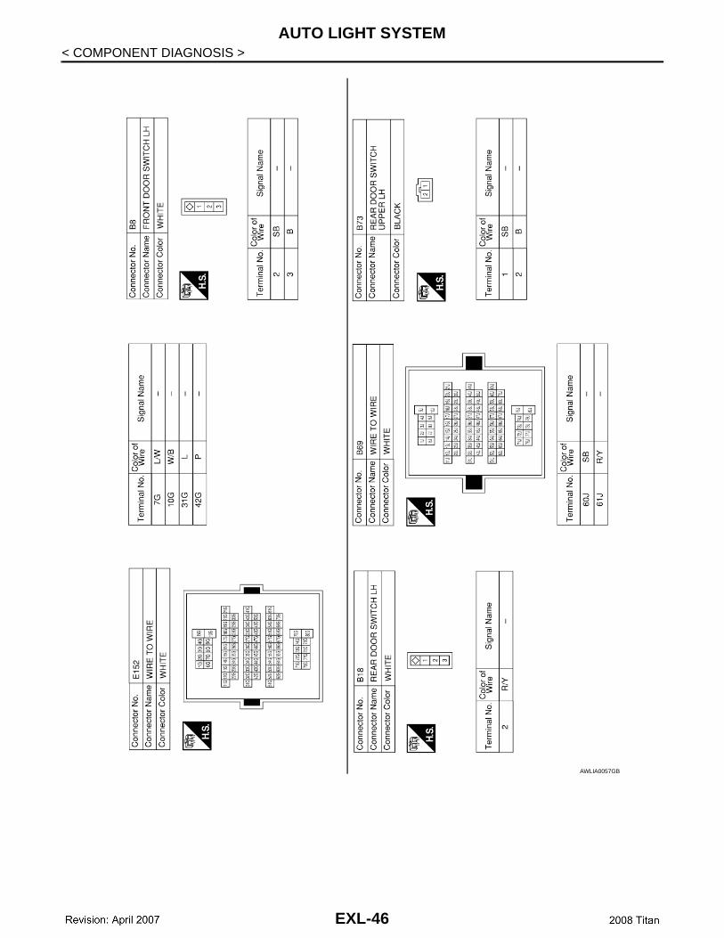
< COMPONENT DIAGNOSIS >AWLIA0057GB
EXL-46

AUTO LIGHT SYSTEM
C
D
E
F
G
H
I
J
K
M
A
B
XL
N
O
P
< COMPONENT DIAGNOSIS >
E
AWLIA0058GB
EXL-47
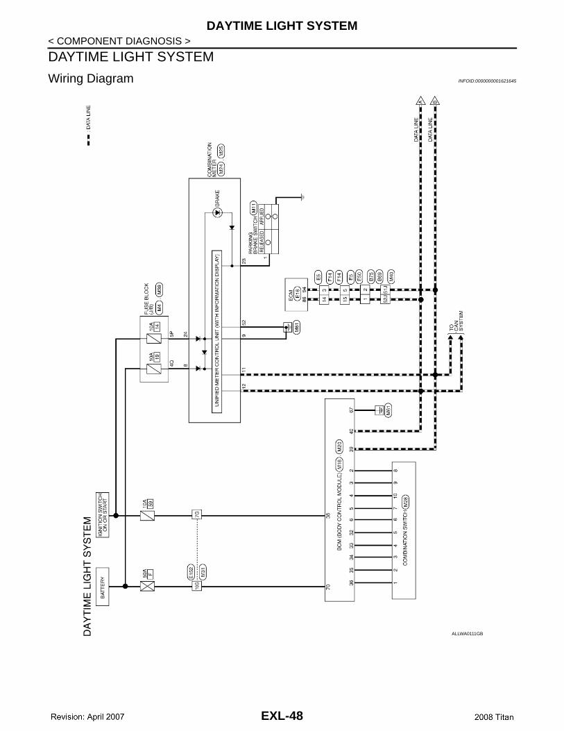
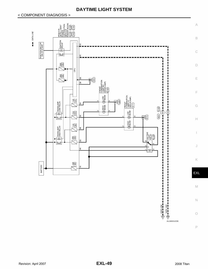
DAYTIME LIGHT SYSTEM
< COMPONENT DIAGNOSIS >DAYTIME LIGHT SYSTEM
Wiring Diagram INFOID:0000000001621645
ALLWA0111GB
EXL-48
DAYTIME LIGHT SYSTEM
C
D
E
F
G
H
I
J
K
M
A
B
XL
N
O
P
< COMPONENT DIAGNOSIS >
E
ALLWA0112GB
EXL-49
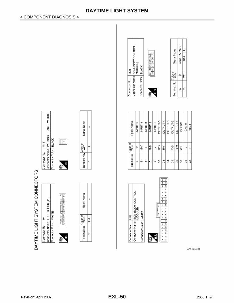
DAYTIME LIGHT SYSTEM
< COMPONENT DIAGNOSIS >AWLIA0060GB
EXL-50
DAYTIME LIGHT SYSTEM
C
D
E
F
G
H
I
J
K
M
A
B
XL
N
O
P
< COMPONENT DIAGNOSIS >
E
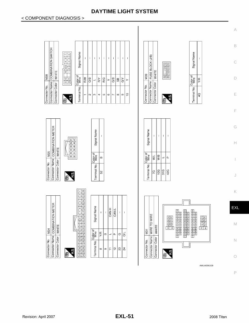
AWLIA0061GB
EXL-51

DAYTIME LIGHT SYSTEM
< COMPONENT DIAGNOSIS >AWLIA0062GB
EXL-52
DAYTIME LIGHT SYSTEM
C
D
E
F
G
H
I
J
K
M
A
B
XL
N
O
P
< COMPONENT DIAGNOSIS >
E
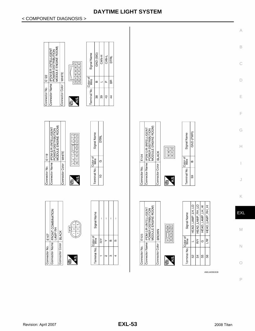
AWLIA0063GB
EXL-53

DAYTIME LIGHT SYSTEM
< COMPONENT DIAGNOSIS >AWLIA0064GB
EXL-54
FRONT FOG LAMP SYSTEM
C
D
E
F
G
H
I
J
K
M
A
B
XL
N
O
P
< COMPONENT DIAGNOSIS >
E
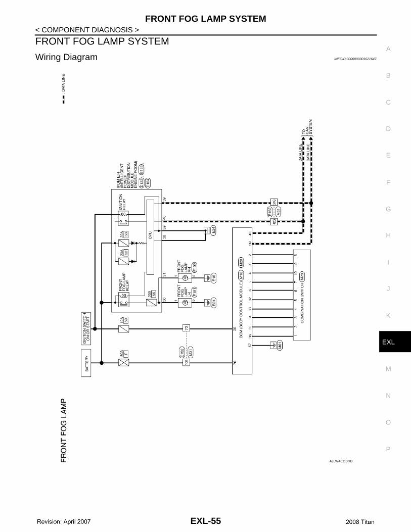
FRONT FOG LAMP SYSTEM
Wiring Diagram INFOID:0000000001621647
ALLWA0113GB
EXL-55
FRONT FOG LAMP SYSTEM
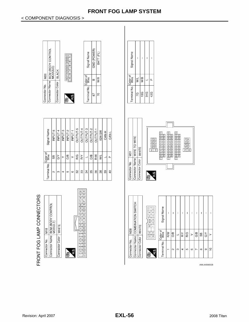
< COMPONENT DIAGNOSIS >AWLIA0065GB
EXL-56
FRONT FOG LAMP SYSTEM
C
D
E
F
G
H
I
J
K
M
A
B
XL
N
O
P
< COMPONENT DIAGNOSIS >
E
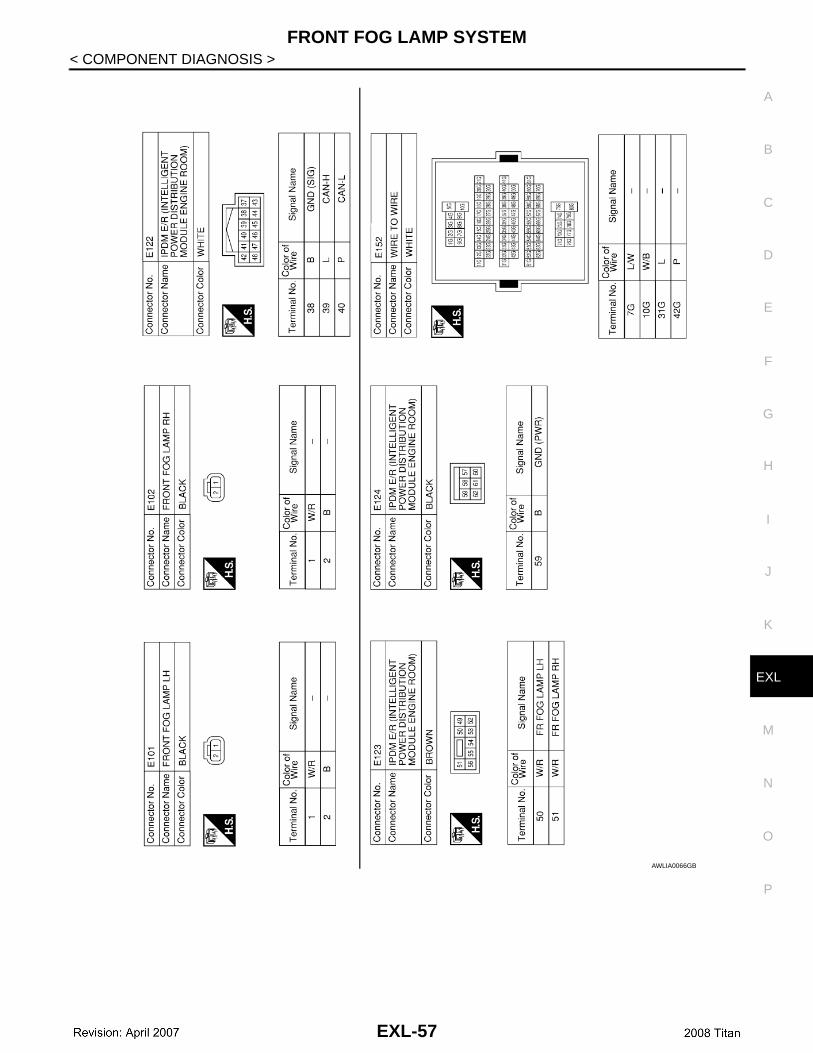
AWLIA0066GB
EXL-57
TURN SIGNAL AND HAZARD WARNING LAMP SYSTEM
< COMPONENT DIAGNOSIS >TURN SIGNAL AND HAZARD WARNING LAMP SYSTEM
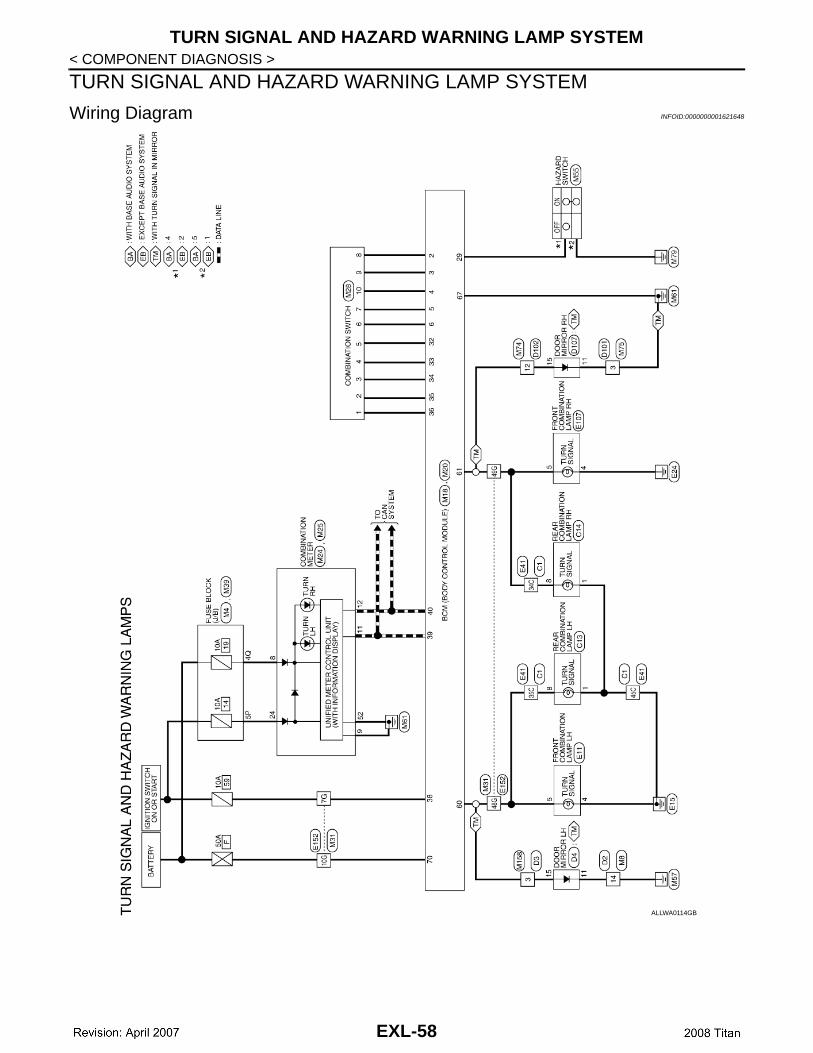
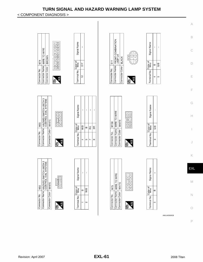
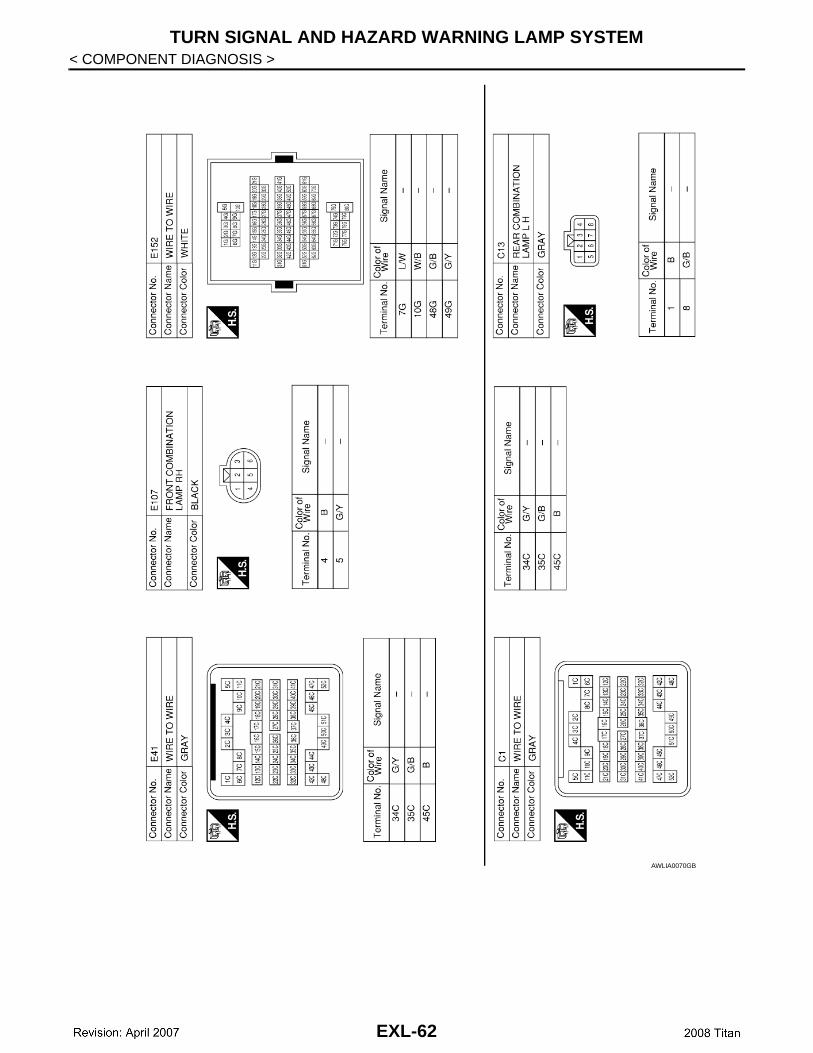
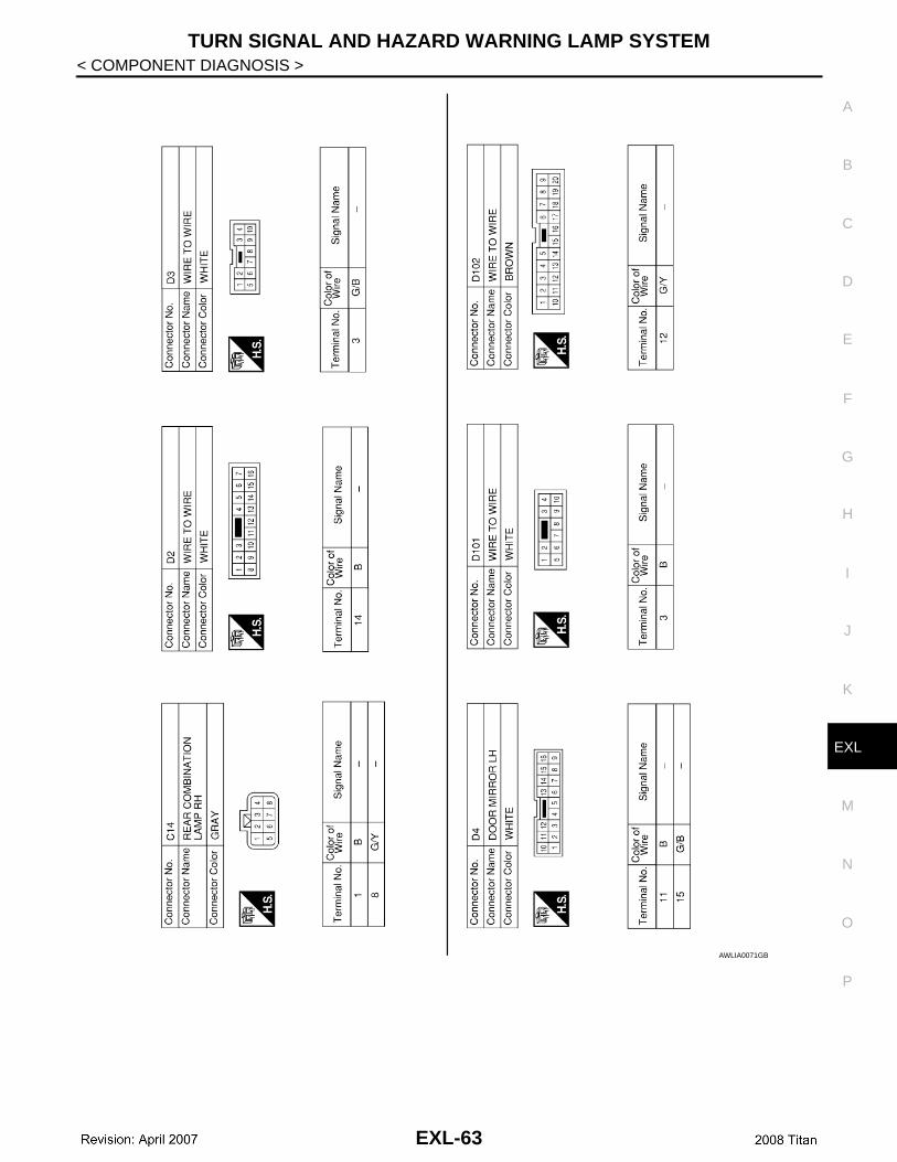
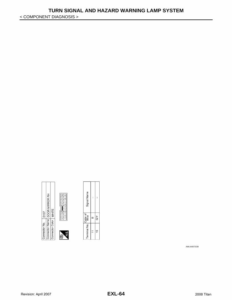
Wiring Diagram INFOID:0000000001621648
ALLWA0114GB
EXL-58
TURN SIGNAL AND HAZARD WARNING LAMP SYSTEM
C
D
E
F
G
H
I
J
K
M
A
B
XL
N
O
P
< COMPONENT DIAGNOSIS >
E
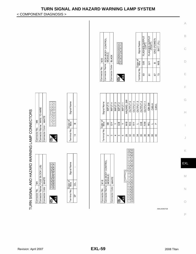
AWLIA0067GB
EXL-59
TURN SIGNAL AND HAZARD WARNING LAMP SYSTEM
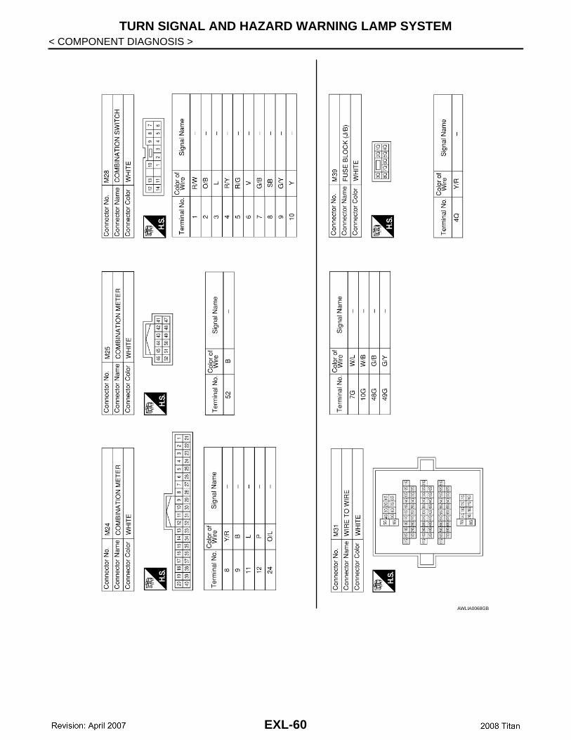
< COMPONENT DIAGNOSIS >AWLIA0068GB
EXL-60
TURN SIGNAL AND HAZARD WARNING LAMP SYSTEM
C
D
E
F
G
H
I
J
K
M
A
B
XL
N
O
P
< COMPONENT DIAGNOSIS >
E
AWLIA0069GB
EXL-61
TURN SIGNAL AND HAZARD WARNING LAMP SYSTEM
< COMPONENT DIAGNOSIS >AWLIA0070GB
EXL-62
TURN SIGNAL AND HAZARD WARNING LAMP SYSTEM
C
D
E
F
G
H
I
J
K
M
A
B
XL
N
O
P
< COMPONENT DIAGNOSIS >
E
AWLIA0071GB
EXL-63
TURN SIGNAL AND HAZARD WARNING LAMP SYSTEM
< COMPONENT DIAGNOSIS >AWLIA0072GB
EXL-64
PARKING, LICENSE PLATE AND TAIL LAMPS SYSTEM
C
D
E
F
G
H
I
J
K
M
A
B
XL
N
O
P
< COMPONENT DIAGNOSIS >
E
PARKING, LICENSE PLATE AND TAIL LAMPS SYSTEM
Wiring Diagram INFOID:0000000001621649
ALLWA0117GB
EXL-65
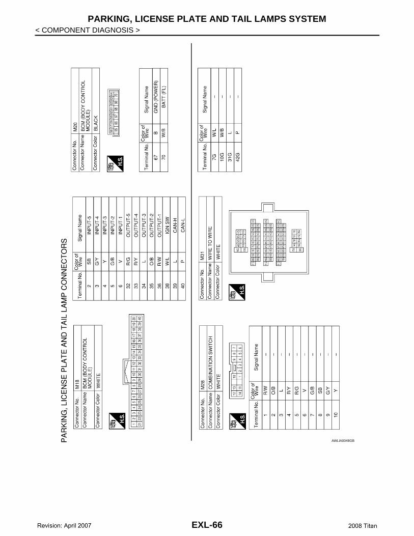
PARKING, LICENSE PLATE AND TAIL LAMPS SYSTEM
< COMPONENT DIAGNOSIS >AWLIA0048GB
EXL-66
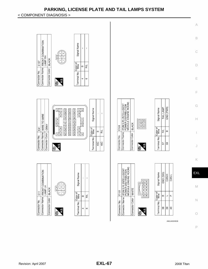
PARKING, LICENSE PLATE AND TAIL LAMPS SYSTEM
C
D
E
F
G
H
I
J
K
M
A
B
XL
N
O
P
< COMPONENT DIAGNOSIS >
E
AWLIA0049GB
EXL-67
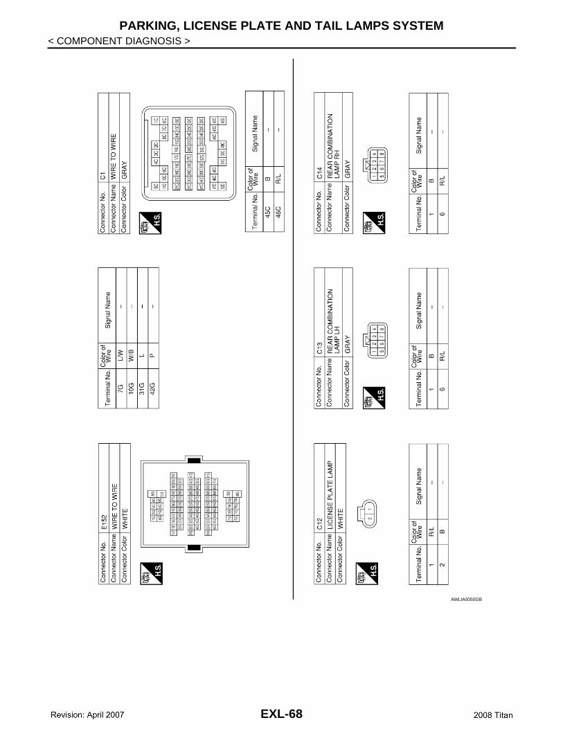
PARKING, LICENSE PLATE AND TAIL LAMPS SYSTEM
< COMPONENT DIAGNOSIS >AWLIA0050GB
EXL-68
STOP LAMP
C
D
E
F
G
H
I
J
K
M
A
B
XL
N
O
P
< COMPONENT DIAGNOSIS >
E
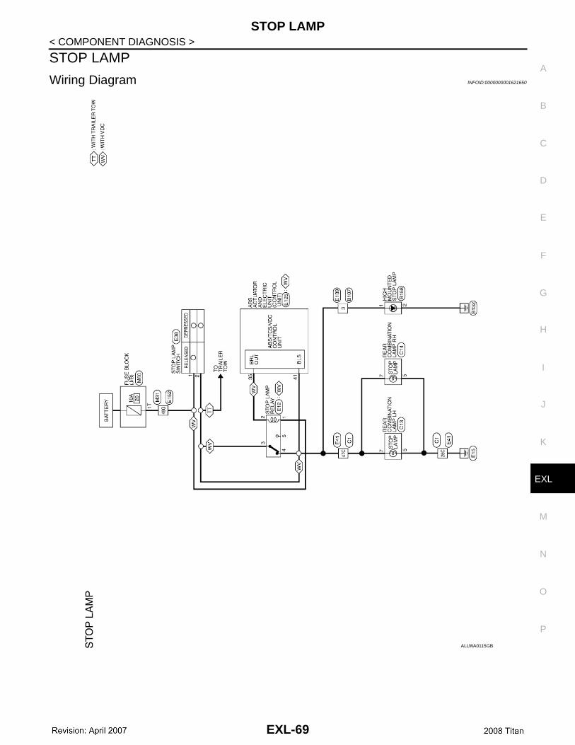
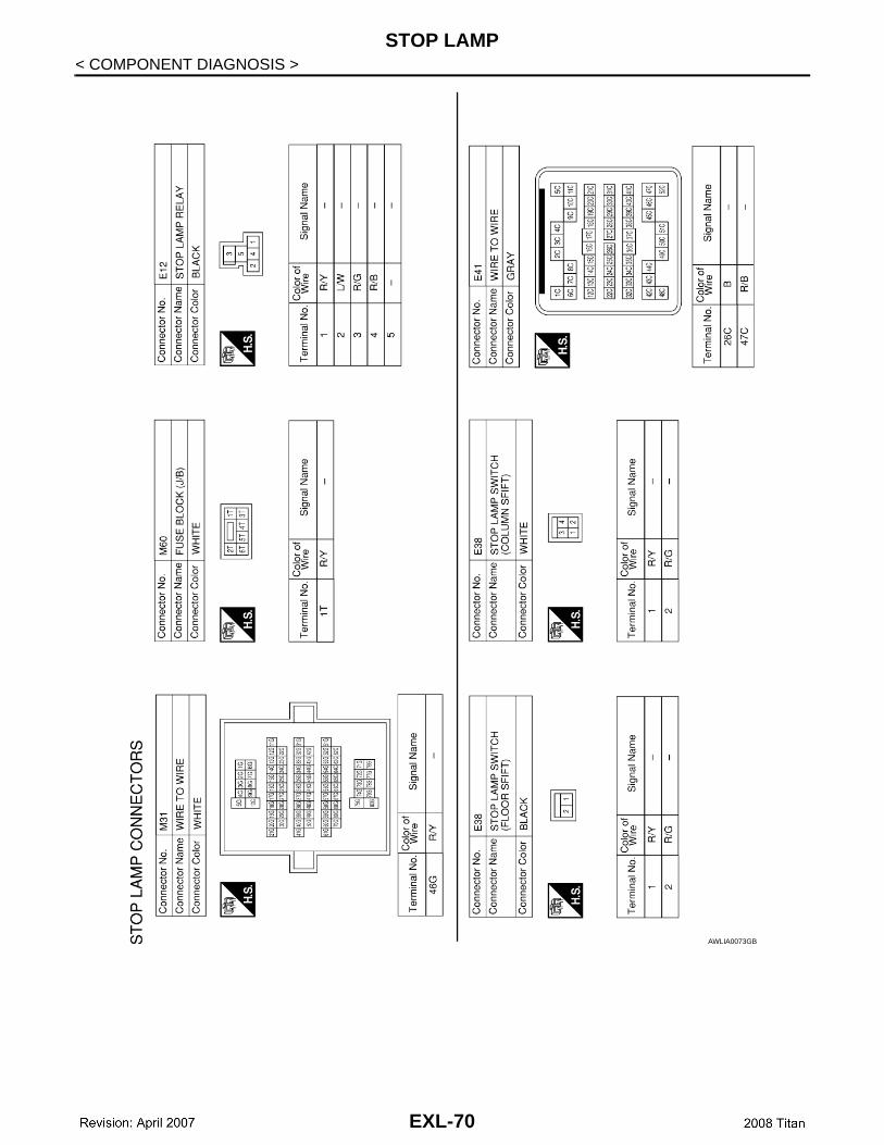
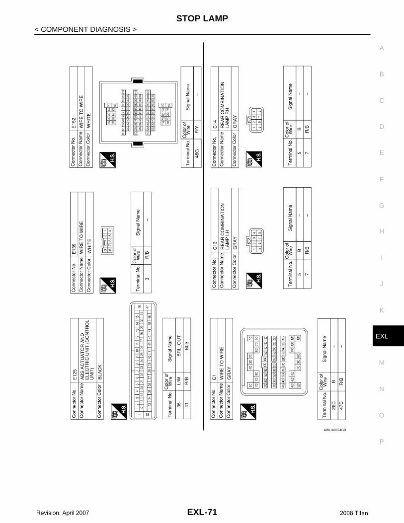
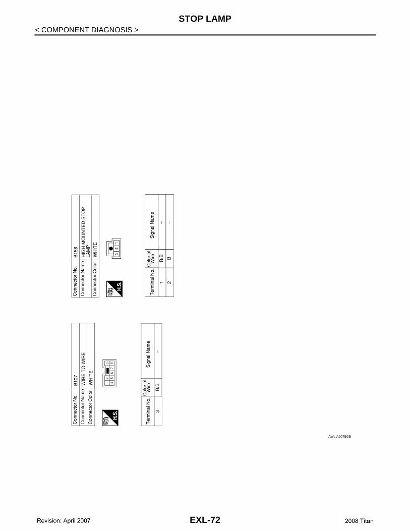
STOP LAMP
Wiring Diagram INFOID:0000000001621650
ALLWA0115GB
EXL-69
STOP LAMP
< COMPONENT DIAGNOSIS >AWLIA0073GB
EXL-70
STOP LAMP
C
D
E
F
G
H
I
J
K
M
A
B
XL
N
O
P
< COMPONENT DIAGNOSIS >
E
AWLIA0074GB
EXL-71
STOP LAMP
< COMPONENT DIAGNOSIS >AWLIA0075GB
EXL-72
BACK-UP LAMP
C
D
E
F
G
H
I
J
K
M
A
B
XL
N
O
P
< COMPONENT DIAGNOSIS >
E
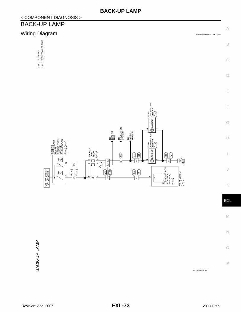
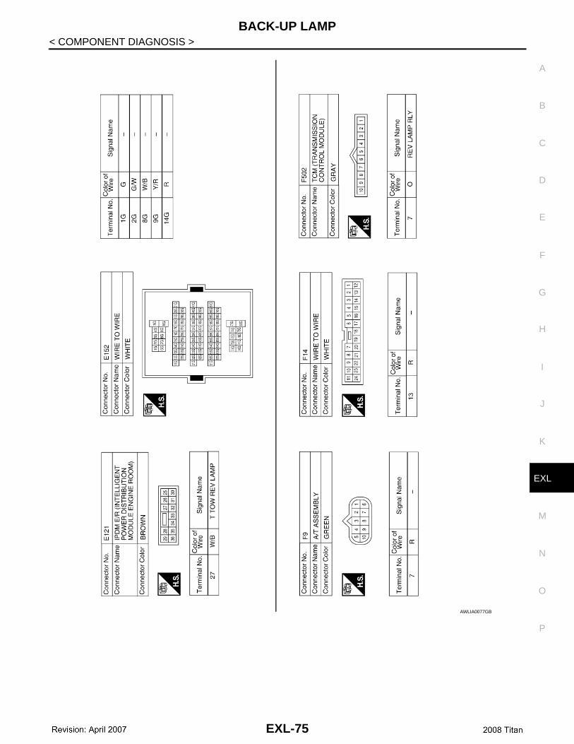
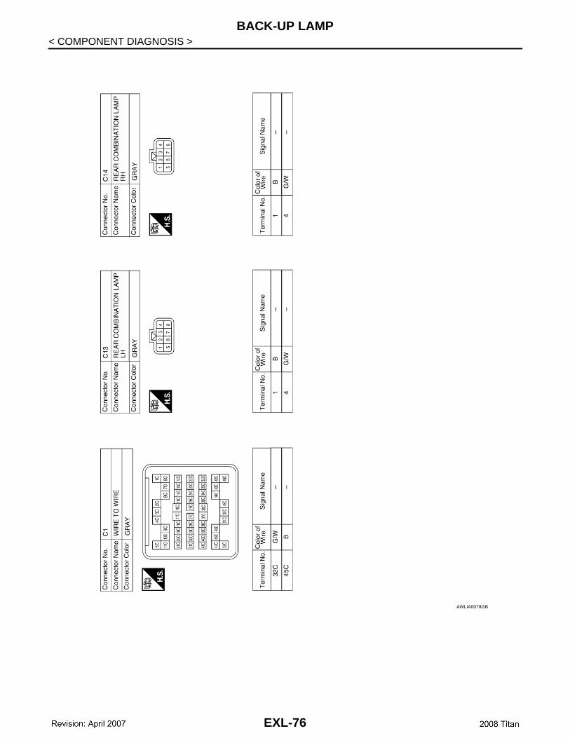
BACK-UP LAMP
Wiring Diagram INFOID:0000000001621651
ALLWA0116GB
EXL-73

BACK-UP LAMP
< COMPONENT DIAGNOSIS >AWLIA0076GB
EXL-74
BACK-UP LAMP
C
D
E
F
G
H
I
J
K
M
A
B
XL
N
O
P
< COMPONENT DIAGNOSIS >
E
AWLIA0077GB
EXL-75
BACK-UP LAMP
< COMPONENT DIAGNOSIS >AWLIA0078GB
EXL-76

TRAILER TOW
C
D
E
F
G
H
I
J
K
M
A
B
XL
N
O
P
< COMPONENT DIAGNOSIS >
E
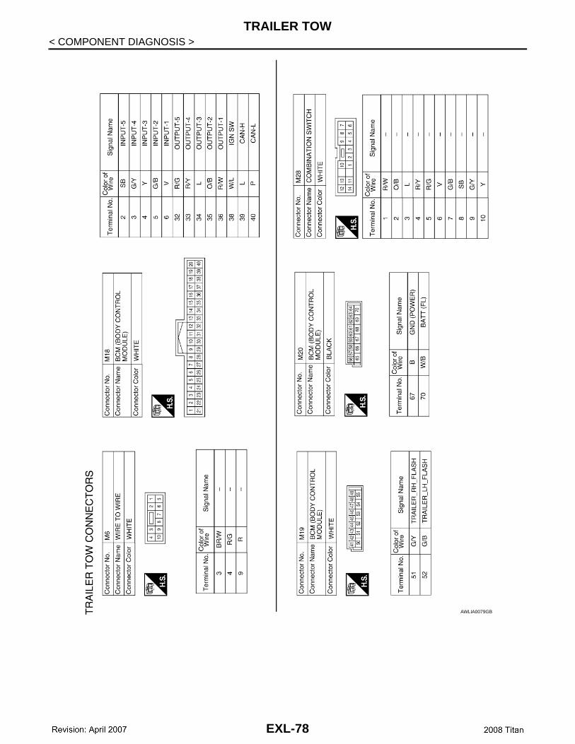
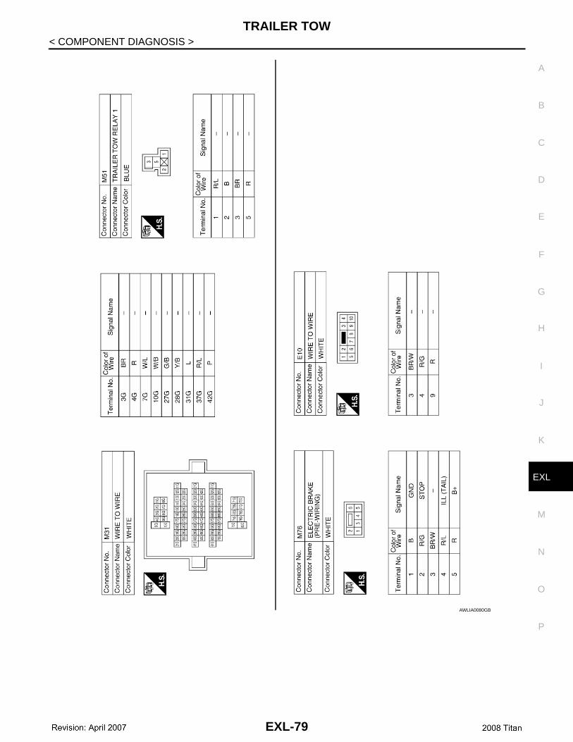
TRAILER TOW
Wiring Diagram INFOID:0000000001621652
ALLWA0118GB
EXL-77
TRAILER TOW
< COMPONENT DIAGNOSIS >AWLIA0079GB
EXL-78
TRAILER TOW
C
D
E
F
G
H
I
J
K
M
A
B
XL
N
O
P
< COMPONENT DIAGNOSIS >
E
AWLIA0080GB
EXL-79
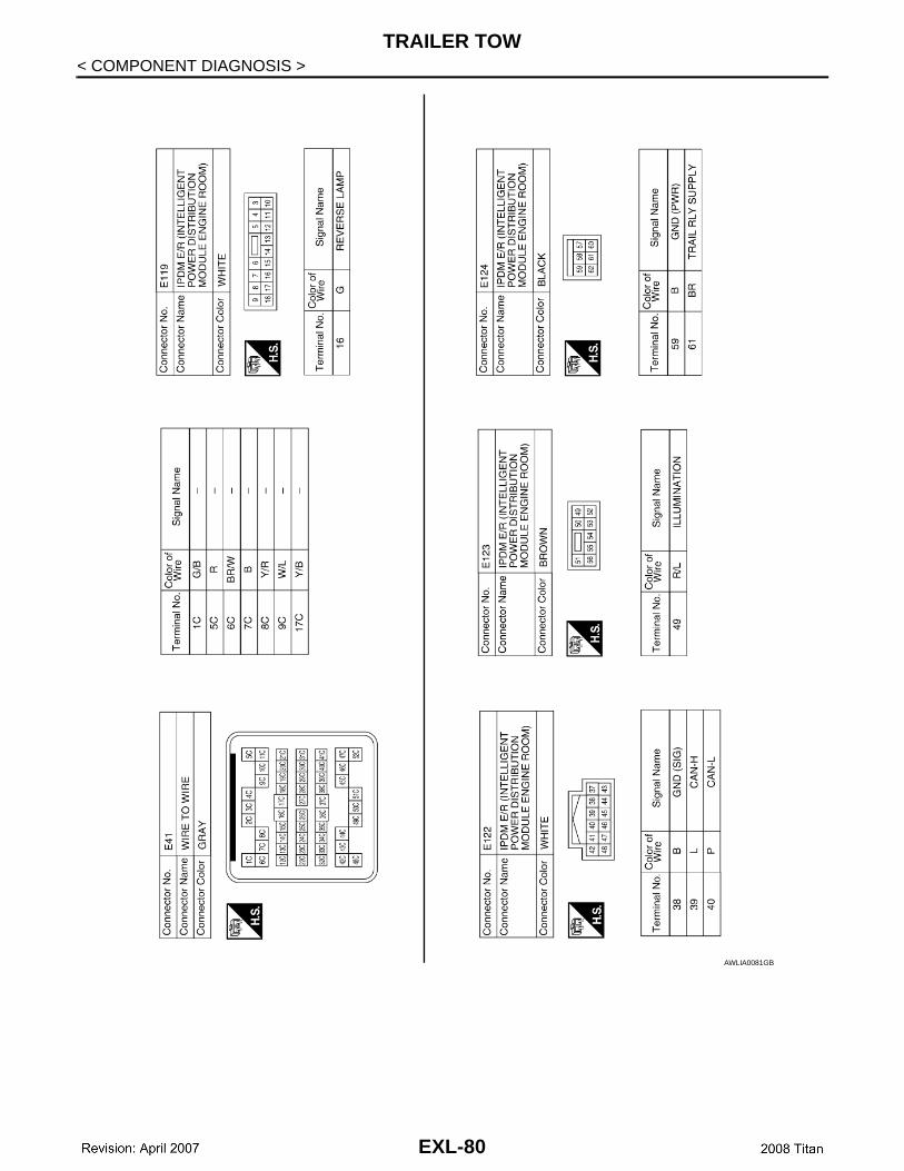
TRAILER TOW
< COMPONENT DIAGNOSIS >AWLIA0081GB
EXL-80
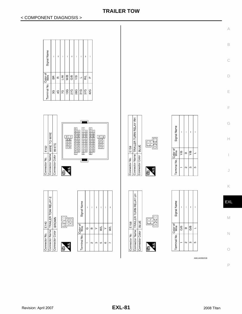
TRAILER TOW
C
D
E
F
G
H
I
J
K
M
A
B
XL
N
O
P
< COMPONENT DIAGNOSIS >
E
AWLIA0082GB
EXL-81
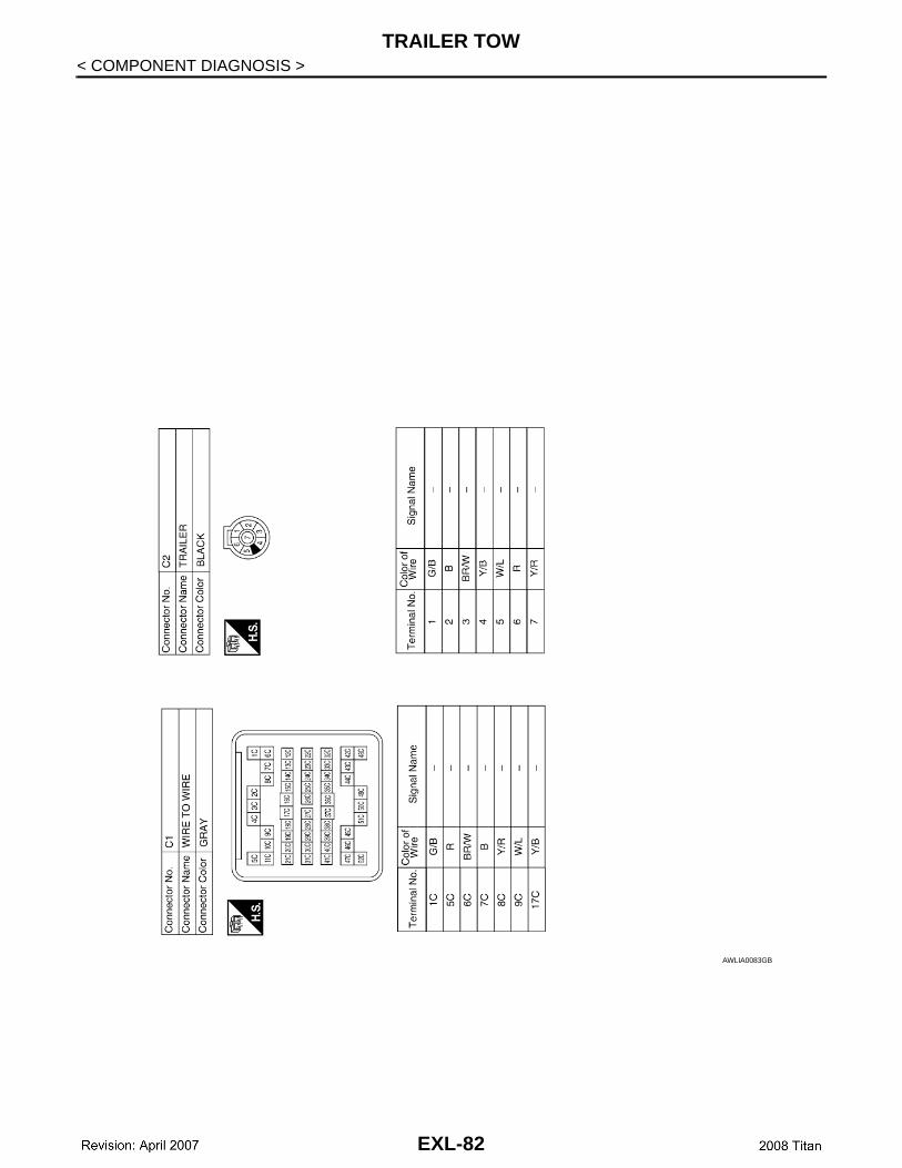
TRAILER TOW
< COMPONENT DIAGNOSIS >AWLIA0083GB
EXL-82
BCM (BODY CONTROL MODULE)
C
D
E
F
G
H
I
J
K
M
A
B
XL
N
O
P
< ECU DIAGNOSIS >
E
ECU DIAGNOSISBCM (BODY CONTROL MODULE)
Description INFOID:0000000001621653
REFERENCE VALUES FOR BCMFor BCM reference values, refer to BCS-35, "Reference Value".
TERMINAL LAYOUT FOR BCMFor the terminal layout for the BCM, refer to BCS-37, "Terminal Layout".
PHYSICAL VALUES FOR BCMFor physical values for the BCM, refer to BCS-37, "Physical Values".
WIRING DIAGRAM - BCMFor the BCM wiring diagram, refer to BCS-43, "Wiring Diagram".
DTC INSPECTION PRIORITY CHART - BCMFor the BCM DTC inspection priority chart, refer to BCS-46, "DTC Inspection Priority Chart".
DTC INDEX - BCMFor the BCM DTC index, refer to BCS-47, "DTC Index".
EXL-83
IPDM E/R (INTELLIGENT POWER DISTRIBUTION MODULE ENGINE ROOM)
< ECU DIAGNOSIS >IPDM E/R (INTELLIGENT POWER DISTRIBUTION MODULE ENGINEROOM)
Description INFOID:0000000001621654
REFERENCE VALUES FOR IPDM E/RFor IPDM E/R reference values, refer to PCS-17, "Reference Value".
TERMINAL LAYOUT FOR IPDM E/RFor the terminal layout for the IPDM E/R, refer to PCS-19, "Terminal Layout".
PHYSICAL VALUES FOR IPDM E/RFor physical values for the IPDM E/R, refer to PCS-19, "Physical Values".
WIRING DIAGRAM - IPDM E/RFor the IPDM E/R wiring diagram, refer to PCS-23, "Wiring Diagram".
FAIL SAFE - IPDM E/RFor IPDM E/R fail safe information, refer to PCS-26, "Fail Safe".
DTC INDEX - IPDM E/RFor the IPDM E/R DTC index, refer to PCS-28, "DTC Index".
EXL-84
EXTERIOR LIGHTING SYSTEM SYMPTOMS
C
D
E
F
G
H
I
J
K
M
A
B
XL
N
O
P
< SYMPTOM DIAGNOSIS >
E
SYMPTOM DIAGNOSISEXTERIOR LIGHTING SYSTEM SYMPTOMS
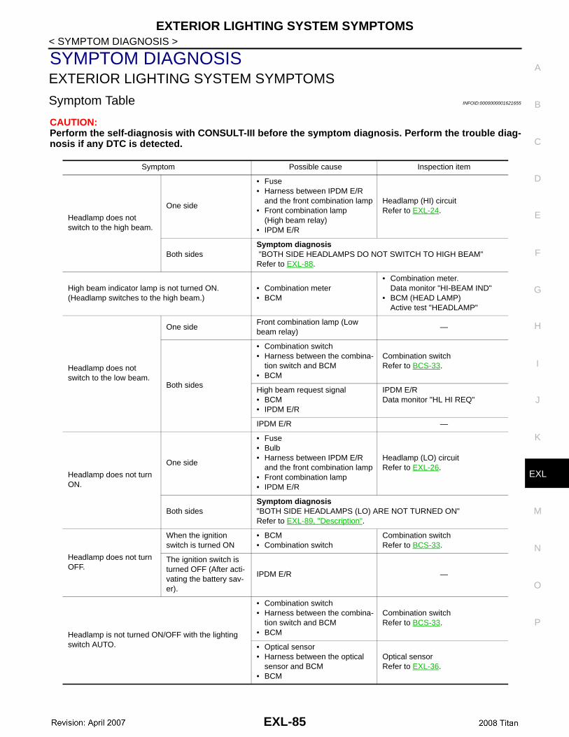
Symptom Table INFOID:0000000001621655
CAUTION:Perform the self-diagnosis with CONSULT-III before the symptom diagnosis. Perform the trouble diag-nosis if any DTC is detected.
Symptom Possible cause Inspection item
Headlamp does not switch to the high beam.
One side
• Fuse• Harness between IPDM E/R
and the front combination lamp• Front combination lamp
(High beam relay)• IPDM E/R
Headlamp (HI) circuitRefer to EXL-24.
Both sidesSymptom diagnosis "BOTH SIDE HEADLAMPS DO NOT SWITCH TO HIGH BEAM"Refer to EXL-88.
High beam indicator lamp is not turned ON.(Headlamp switches to the high beam.)
• Combination meter• BCM
• Combination meter. Data monitor "HI-BEAM IND"
• BCM (HEAD LAMP)Active test "HEADLAMP"
Headlamp does not switch to the low beam.
One sideFront combination lamp (Low beam relay)
—
Both sides
• Combination switch• Harness between the combina-
tion switch and BCM• BCM
Combination switchRefer to BCS-33.
High beam request signal• BCM• IPDM E/R
IPDM E/RData monitor "HL HI REQ"
IPDM E/R —
Headlamp does not turn ON.
One side
• Fuse• Bulb• Harness between IPDM E/R
and the front combination lamp• Front combination lamp• IPDM E/R
Headlamp (LO) circuitRefer to EXL-26.
Both sidesSymptom diagnosis"BOTH SIDE HEADLAMPS (LO) ARE NOT TURNED ON"Refer to EXL-89, "Description".
Headlamp does not turn OFF.
When the ignition switch is turned ON
• BCM• Combination switch
Combination switchRefer to BCS-33.
The ignition switch is turned OFF (After acti-vating the battery sav-er).
IPDM E/R —
Headlamp is not turned ON/OFF with the lighting switch AUTO.
• Combination switch• Harness between the combina-
tion switch and BCM• BCM
Combination switchRefer to BCS-33.
• Optical sensor• Harness between the optical
sensor and BCM• BCM
Optical sensorRefer to EXL-36.
EXL-85

EXTERIOR LIGHTING SYSTEM SYMPTOMS
< SYMPTOM DIAGNOSIS >Daytime light system does not activate.
• Either high beam bulb• Parking brake switch• Combination switch• BCM• IPDM E/R• Daytime light relay• Harness between IPDM E/R
and daytime light relay.
Daytime light system description. Refer to EXL-11, "System Descrip-tion".
Front fog lamp is not turned ON.
One side
• Front fog lamp bulb• Harness between IPDM E/R
and the front combination lamp• Front combination lamp• IPDM E/R
Front fog lamp circuitRefer to EXL-28.
Both sideSymptom diagnosis"BOTH SIDE FRONT FOG LAMPS ARE NOT TURNED ON"Refer to EXL-91.
Parking lamp is not turned ON.
One side
• Fuse• Parking lamp bulb• Harness between IPDM E/R
and the front/rear combination lamp
• Front/rear combination lamp• IPDM E/R
Parking lamp circuitRefer to EXL-30.
Both sides
Symptom diagnosis"PARKING, LICENSE PLATE AND TAIL LAMPS ARE NOT TURNED ON"Refer to EXL-90.
Turn signal lamp does not blink.
Indicator lamp is nor-mal.(The applicable side performs the high flash-er activation).
• Harness between BCM and each turn signal lamp
• Turn signal lamp bulb• Door mirror (if equipped with
turn signals in the door mirrors)
Turn signal lamp circuitRefer to EXL-33.
Turn signal indicator lamp does not blink.
One side Combination meter —
Both sides(Always)
• Turn signal indicator lamp sig-nal
• Combination meter• BCM
• Combination meter. Data monitor "TURN IND"
• BCM (FLASHER)Active test "FLASHER"
Both sides(Does blink when acti-vating the hazard warn-ing lamp with the ignition switch OFF)
• The combination meter power supply and the ground circuit
• Combination meter
Combination meterPower supply and the ground circuitRefer to MWI-32.
Symptom Possible cause Inspection item
EXL-86
NORMAL OPERATING CONDITION
C
D
E
F
G
H
I
J
K
M
A
B
XL
N
O
P
< SYMPTOM DIAGNOSIS >
E
NORMAL OPERATING CONDITION
Description INFOID:0000000001621656
AUTO LIGHT SYSTEMThe auto light system may not turn the headlamp ON/OFF immediately after passing a dark area or a brightarea (short tunnel, sky bridge, shadowed area etc.). This is normal.
EXL-87

BOTH SIDE HEADLAMPS DO NOT SWITCH TO HIGH BEAM
< SYMPTOM DIAGNOSIS >BOTH SIDE HEADLAMPS DO NOT SWITCH TO HIGH BEAM
Description INFOID:0000000001621657
The headlamps (both sides) do not switch to high beam when the lighting switch is in the HI or PASS setting.
Diagnosis Procedure INFOID:0000000001621658
1.COMBINATION SWITCH INSPECTION
Check the combination switch. Refer to BCS-33, "Diagnosis Procedure".Is the combination switch normal?YES >> GO TO 2NO >> Repair or replace the malfunctioning part.
2.CHECK HEADLAMP (HI) REQUEST SIGNAL INPUT
CONSULT-III DATA MONITOR1. Select "HL HI REQ" of IPDM E/R DATA MONITOR item.2. With operating the lighting switch, check the monitor status.
Is the item status normal?YES >> GO TO 3NO >> Replace BCM. Refer to BCS-50, "Removal and Installation" .
3.HEADLAMP (HI) CIRCUIT INSPECTION
Check the headlamp (HI) circuit. Refer to EXL-24, "Description".Is the headlamp (HI) circuit normal?YES >> Replace IPDM E/R. Refer to PCS-30, "Removal and Installation of IPDM E/R" .NO >> Repair or replace the malfunctioning part.
Monitor item Condition Monitor status
HL HI REQLighting switch(2ND)
HI or PASS ON
Except for HI or PASS
OFF
EXL-88
BOTH SIDE HEADLAMPS (LO) ARE NOT TURNED ON
C
D
E
F
G
H
I
J
K
M
A
B
XL
N
O
P
< SYMPTOM DIAGNOSIS >
E
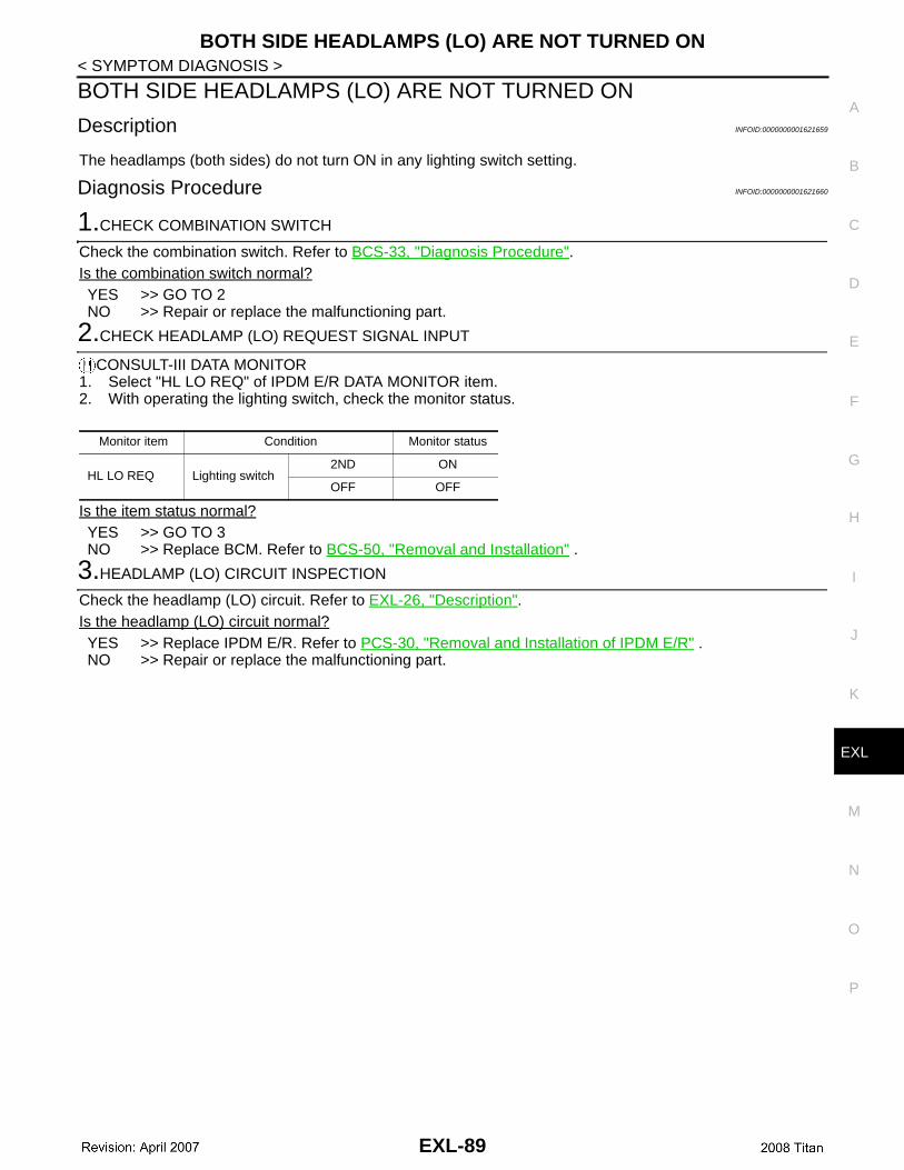
BOTH SIDE HEADLAMPS (LO) ARE NOT TURNED ON
Description INFOID:0000000001621659
The headlamps (both sides) do not turn ON in any lighting switch setting.
Diagnosis Procedure INFOID:0000000001621660
1.CHECK COMBINATION SWITCH
Check the combination switch. Refer to BCS-33, "Diagnosis Procedure".Is the combination switch normal?YES >> GO TO 2NO >> Repair or replace the malfunctioning part.
2.CHECK HEADLAMP (LO) REQUEST SIGNAL INPUT
CONSULT-III DATA MONITOR1. Select "HL LO REQ" of IPDM E/R DATA MONITOR item.2. With operating the lighting switch, check the monitor status.
Is the item status normal?YES >> GO TO 3NO >> Replace BCM. Refer to BCS-50, "Removal and Installation" .
3.HEADLAMP (LO) CIRCUIT INSPECTION
Check the headlamp (LO) circuit. Refer to EXL-26, "Description".Is the headlamp (LO) circuit normal?YES >> Replace IPDM E/R. Refer to PCS-30, "Removal and Installation of IPDM E/R" .NO >> Repair or replace the malfunctioning part.
Monitor item Condition Monitor status
HL LO REQ Lighting switch2ND ON
OFF OFF
EXL-89

PARKING, LICENSE PLATE AND TAIL LAMPS ARE NOT TURNED ON
< SYMPTOM DIAGNOSIS >PARKING, LICENSE PLATE AND TAIL LAMPS ARE NOT TURNED ON
Description INFOID:0000000001621661
The parking, license plate and tail lamps do not turn ON in with any lighting switch setting.
Diagnosis Procedure INFOID:0000000001621662
1.COMBINATION SWITCH INSPECTION
Check the combination switch. Refer to BCS-33, "Diagnosis Procedure".Is the combination switch normal?YES >> GO TO 2NO >> Repair or replace the malfunctioning part.
2.CHECK TAIL LAMP RELAY REQUEST SIGNAL INPUT
CONSULT-III DATA MONITOR1. Select "TAIL & CLR REQ" of IPDM E/R DATA MONITOR item.2. With operating the lighting switch, check the monitor status.
Is the item status normal?YES >> GO TO 3NO >> Replace BCM. Refer to BCS-50, "Removal and Installation".
3.PARK LAMP CIRCUIT INSPECTION
Check the parking lamp circuit. Refer to EXL-30, "Description".Is the tail lamp circuit normal?YES >> Replace IPDM E/R. Refer to PCS-30, "Removal and Installation of IPDM E/R".NO >> Repair or replace the malfunctioning part.
Monitor item Condition Monitor status
TAIL & CLR REQ
Lighting switch1ST ON
OFF OFF
EXL-90

BOTH SIDE FRONT FOG LAMPS ARE NOT TURNED ON
C
D
E
F
G
H
I
J
K
M
A
B
XL
N
O
P
< SYMPTOM DIAGNOSIS >
E
BOTH SIDE FRONT FOG LAMPS ARE NOT TURNED ON
Description INFOID:0000000001621663
The front fog lamps do not turn ON in any setting.
Diagnosis Procedure INFOID:0000000001621664
1.COMBINATION SWITCH INSPECTION
Check the combination switch. Refer to BCS-33, "Diagnosis Procedure".Is the combination switch normal?YES >> GO TO 2NO >> Repair or replace the malfunctioning part.
2.CHECK FRONT FOG LAMP REQUEST SIGNAL INPUT
CONSULT-III DATA MONITOR1. Select "FR FOG REQ" of IPDM E/R DATA MONITOR item.2. With operating the front fog lamp switch, check the monitor status.
Is the item status normal?YES >> GO TO 3NO >> Replace BCM. Refer to BCS-50, "Removal and Installation".
3.FRONT FOG LAMP CIRCUIT INSPECTION
Check the front fog lamp circuit. Refer to EXL-28, "Description".Is the front fog lamp circuit normal?YES >> Replace IPDM E/R. Refer to PCS-30, "Removal and Installation of IPDM E/R".NO >> Repair or replace the malfunctioning part.
Monitor item Condition Monitor status
FR FOG REQFront fog lamp switch(Lighting switch 2ND)
ON ON
OFF OFF
EXL-91
HEADLAMP
< ON-VEHICLE REPAIR >ON-VEHICLE REPAIRHEADLAMP
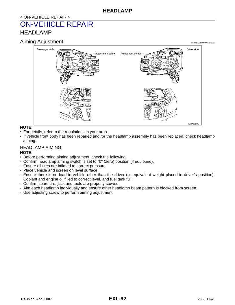
Aiming Adjustment INFOID:0000000001396317
NOTE:• For details, refer to the regulations in your area.• If vehicle front body has been repaired and /or the headlamp assembly has been replaced, check headlamp
aiming.
HEADLAMP AIMINGNOTE:• Before performing aiming adjustment, check the following:- Confirm headlamp aiming switch is set to "0" (zero) position (if equipped).- Ensure all tires are inflated to correct pressure.- Place vehicle and screen on level surface.- Ensure there is no load in vehicle other than the driver (or equivalent weight placed in driver's position).
Coolant and engine oil filled to correct level, and fuel tank full.- Confirm spare tire, jack and tools are properly stowed.- Aim each headlamp individually and ensure other headlamp beam pattern is blocked from screen.- Use adjusting screw to perform aiming adjustment.
WKIA1398E
EXL-92
HEADLAMP
C
D
E
F
G
H
I
J
K
M
A
B
XL
N
O
P
< ON-VEHICLE REPAIR >
E
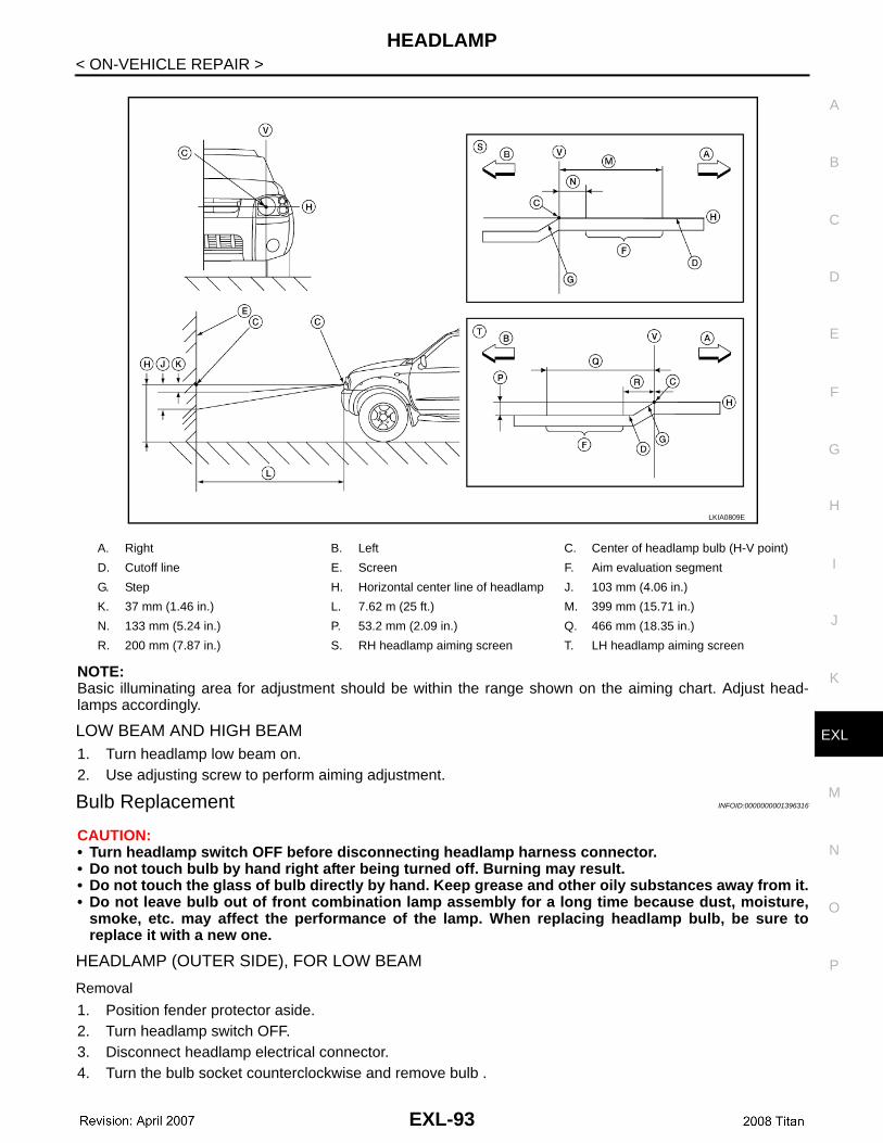
NOTE:Basic illuminating area for adjustment should be within the range shown on the aiming chart. Adjust head-lamps accordingly.
LOW BEAM AND HIGH BEAM1. Turn headlamp low beam on.2. Use adjusting screw to perform aiming adjustment.
Bulb Replacement INFOID:0000000001396316
CAUTION:• Turn headlamp switch OFF before disconnecting headlamp harness connector. • Do not touch bulb by hand right after being turned off. Burning may result.• Do not touch the glass of bulb directly by hand. Keep grease and other oily substances away from it.• Do not leave bulb out of front combination lamp assembly for a long time because dust, moisture,
smoke, etc. may affect the performance of the lamp. When replacing headlamp bulb, be sure toreplace it with a new one.
HEADLAMP (OUTER SIDE), FOR LOW BEAM
Removal
1. Position fender protector aside.2. Turn headlamp switch OFF.3. Disconnect headlamp electrical connector.4. Turn the bulb socket counterclockwise and remove bulb .
A. Right B. Left C. Center of headlamp bulb (H-V point)
D. Cutoff line E. Screen F. Aim evaluation segment
G. Step H. Horizontal center line of headlamp J. 103 mm (4.06 in.)
K. 37 mm (1.46 in.) L. 7.62 m (25 ft.) M. 399 mm (15.71 in.)
N. 133 mm (5.24 in.) P. 53.2 mm (2.09 in.) Q. 466 mm (18.35 in.)
R. 200 mm (7.87 in.) S. RH headlamp aiming screen T. LH headlamp aiming screen
LKIA0809E
EXL-93
HEADLAMP
< ON-VEHICLE REPAIR >InstallationInstallation is in the reverse order of removal.HEADLAMP (INNER SIDE), FOR HIGH BEAM
Removal
1. Turn headlamp switch OFF.2. Disconnect headlamp electrical connector.3. Turn the bulb socket counterclockwise and remove bulb.
InstallationInstallation is in the reverse order of removal.
TURN SIGNAL/PARKING LAMP (FRONT)NOTE:Reach through wheel opening for access.
Removal
1. Turn the bulb socket counterclockwise to unlock.2. Pull the bulb to remove from the socket.
InstallationInstallation is in the reverse order of removal.
SIDE MARKER LAMP (FRONT)
RemovalNOTE:Reach through wheel opening for access.1. Turn the side marker lamp (front) bulb socket counterclockwise and remove side marker lamp (front) bulb
socket.2. Pull to remove side marker lamp (front) from the side marker lamp (front) bulb socket.
InstallationInstallation is in the reverse order of removal.
Removal and Installation INFOID:0000000001396315
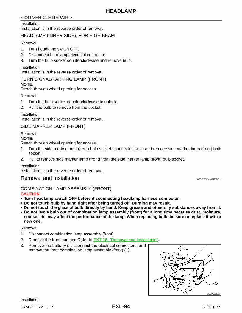
COMBINATION LAMP ASSEMBLY (FRONT)CAUTION:• Turn headlamp switch OFF before disconnecting headlamp harness connector. • Do not touch bulb by hand right after being turned off. Burning may result.• Do not touch the glass of bulb directly by hand. Keep grease and other oily substances away from it.• Do not leave bulb out of combination lamp assembly (front) for a long time because dust, moisture,
smoke, etc. may affect the performance of the lamp. When replacing bulb, be sure to replace it with anew one.
Removal
1. Disconnect combination lamp assembly (front). 2. Remove the front bumper. Refer to EXT-16, "Removal and Installation".3. Remove the bolts (A), disconnect the electrical connectors, and
remove the front combination lamp assembly (front) (1).
Installation
ALLIA0330ZZ
EXL-94
HEADLAMP
C
D
E
F
G
H
I
J
K
M
A
B
XL
N
O
P
< ON-VEHICLE REPAIR >
E
Installation is in the reverse order of removal.
Disassembly and Assembly INFOID:0000000001396318
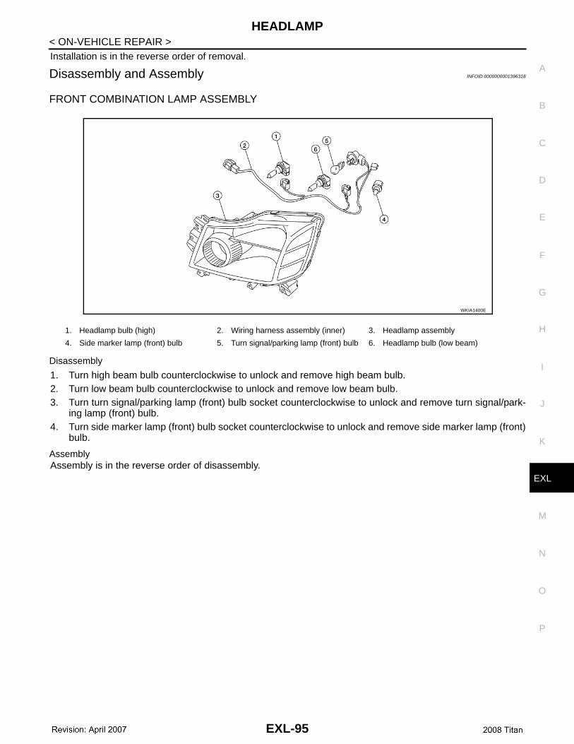
FRONT COMBINATION LAMP ASSEMBLY
Disassembly
1. Turn high beam bulb counterclockwise to unlock and remove high beam bulb.2. Turn low beam bulb counterclockwise to unlock and remove low beam bulb.3. Turn turn signal/parking lamp (front) bulb socket counterclockwise to unlock and remove turn signal/park-
ing lamp (front) bulb.4. Turn side marker lamp (front) bulb socket counterclockwise to unlock and remove side marker lamp (front)
bulb.
AssemblyAssembly is in the reverse order of disassembly.
1. Headlamp bulb (high) 2. Wiring harness assembly (inner) 3. Headlamp assembly
4. Side marker lamp (front) bulb 5. Turn signal/parking lamp (front) bulb 6. Headlamp bulb (low beam)
WKIA1400E
EXL-95
AUTO LIGHT SYSTEM
< ON-VEHICLE REPAIR >AUTO LIGHT SYSTEM
Removal and Installation INFOID:0000000001396319
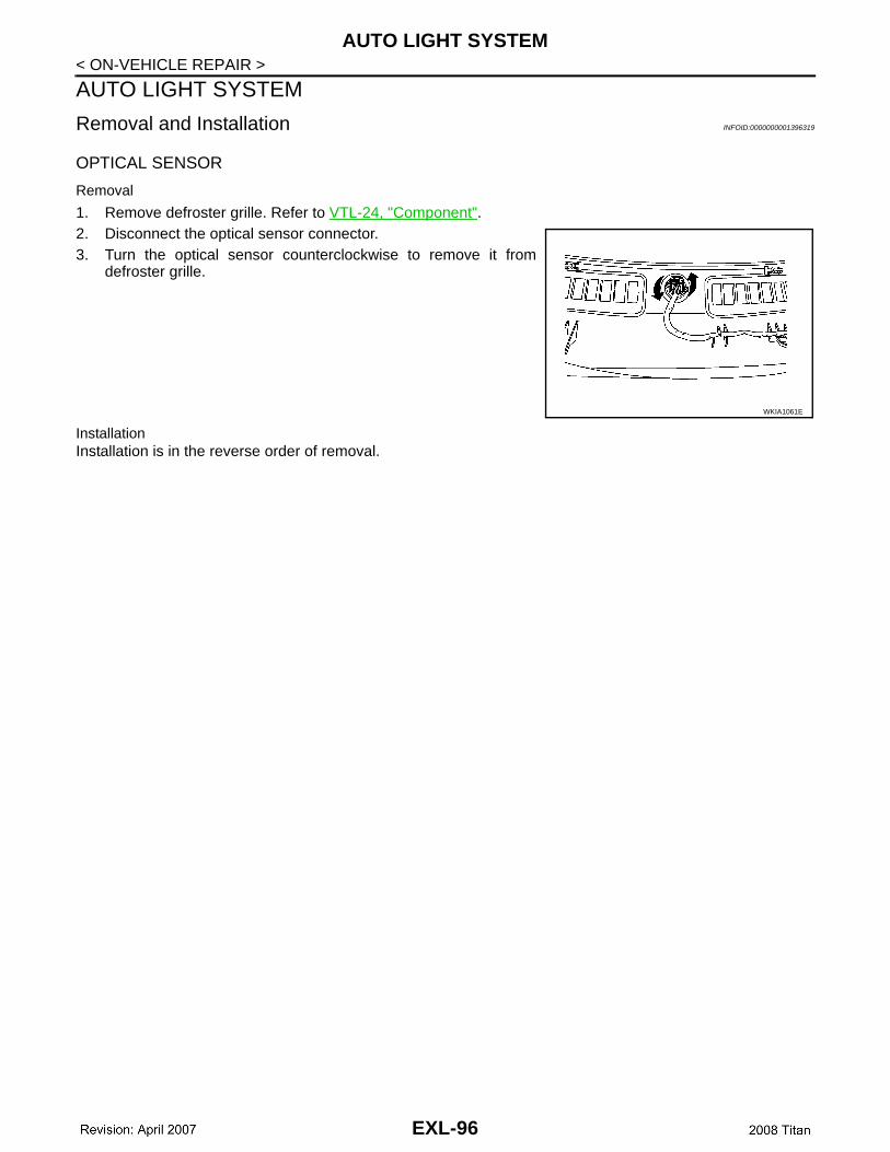
OPTICAL SENSOR
Removal
1. Remove defroster grille. Refer to VTL-24, "Component".2. Disconnect the optical sensor connector.3. Turn the optical sensor counterclockwise to remove it from
defroster grille.
InstallationInstallation is in the reverse order of removal.
WKIA1061E
EXL-96
FRONT FOG LAMP
C
D
E
F
G
H
I
J
K
M
A
B
XL
N
O
P
< ON-VEHICLE REPAIR >
E
FRONT FOG LAMP
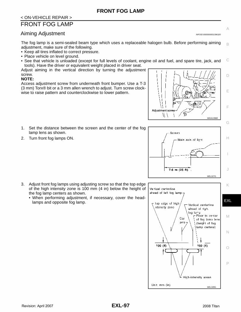
Aiming Adjustment INFOID:0000000001396320
The fog lamp is a semi-sealed beam type which uses a replaceable halogen bulb. Before performing aimingadjustment, make sure of the following.• Keep all tires inflated to correct pressure.• Place vehicle on level ground.• See that vehicle is unloaded (except for full levels of coolant, engine oil and fuel, and spare tire, jack, and
tools). Have the driver or equivalent weight placed in driver seat.Adjust aiming in the vertical direction by turning the adjustmentscrew.NOTE:Access adjustment screw from underneath front bumper. Use a T-3(3 mm) Torx® bit or a 3 mm allen wrench to adjust. Turn screw clock-wise to raise pattern and counterclockwise to lower pattern.
1. Set the distance between the screen and the center of the foglamp lens as shown.
2. Turn front fog lamps ON.
3. Adjust front fog lamps using adjusting screw so that the top edgeof the high intensity zone is 100 mm (4 in) below the height ofthe fog lamp centers as shown.• When performing adjustment, if necessary, cover the head-
lamps and opposite fog lamp.
WKIA1396E
MEL327G
MEL328G
EXL-97
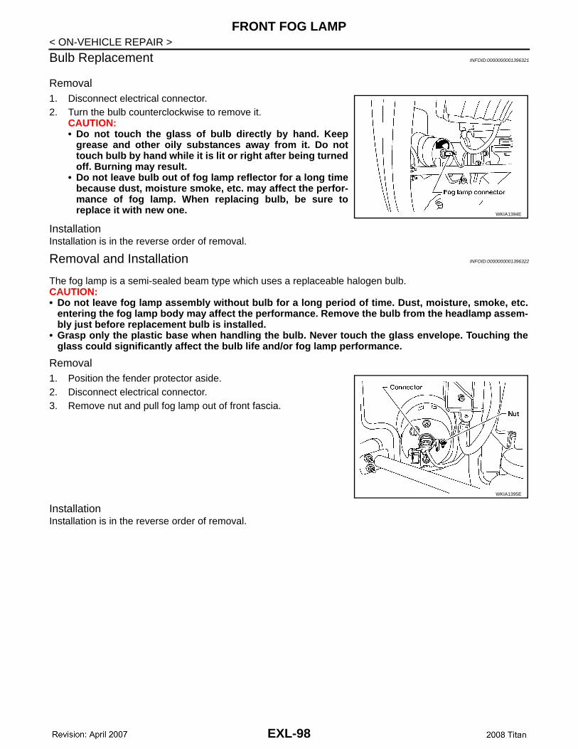
FRONT FOG LAMP
< ON-VEHICLE REPAIR >Bulb Replacement INFOID:0000000001396321
Removal1. Disconnect electrical connector.2. Turn the bulb counterclockwise to remove it.
CAUTION:• Do not touch the glass of bulb directly by hand. Keep
grease and other oily substances away from it. Do nottouch bulb by hand while it is lit or right after being turnedoff. Burning may result.
• Do not leave bulb out of fog lamp reflector for a long timebecause dust, moisture smoke, etc. may affect the perfor-mance of fog lamp. When replacing bulb, be sure toreplace it with new one.
InstallationInstallation is in the reverse order of removal.
Removal and Installation INFOID:0000000001396322
The fog lamp is a semi-sealed beam type which uses a replaceable halogen bulb.CAUTION:• Do not leave fog lamp assembly without bulb for a long period of time. Dust, moisture, smoke, etc.
entering the fog lamp body may affect the performance. Remove the bulb from the headlamp assem-bly just before replacement bulb is installed.
• Grasp only the plastic base when handling the bulb. Never touch the glass envelope. Touching theglass could significantly affect the bulb life and/or fog lamp performance.
Removal1. Position the fender protector aside.2. Disconnect electrical connector.3. Remove nut and pull fog lamp out of front fascia.
InstallationInstallation is in the reverse order of removal.
WKIA1394E
WKIA1395E
EXL-98

LIGHTING & TURN SIGNAL SWITCH
C
D
E
F
G
H
I
J
K
M
A
B
XL
N
O
P
< ON-VEHICLE REPAIR >
E
LIGHTING & TURN SIGNAL SWITCH
Removal and Installation INFOID:0000000001396325
REMOVAL1. Remove steering column cover. Refer to IP-10, "Exploded
View".2. While pressing tabs, pull lighting and turn signal switch toward
driver door and disconnect from the base.
INSTALLATIONInstallation is in the reverse order of removal.
LKIA0013E
EXL-99
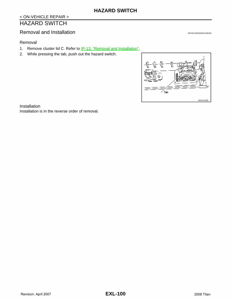
HAZARD SWITCH
< ON-VEHICLE REPAIR >HAZARD SWITCH
Removal and Installation INFOID:0000000001396326
Removal1. Remove cluster lid C. Refer to IP-13, "Removal and Installation".2. While pressing the tab, push out the hazard switch.
InstallationInstallation is in the reverse order of removal.
WKIA1402E
EXL-100
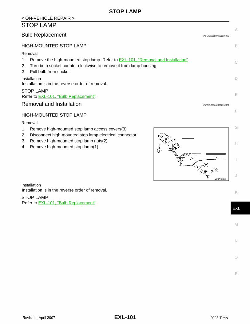
STOP LAMP
C
D
E
F
G
H
I
J
K
M
A
B
XL
N
O
P
< ON-VEHICLE REPAIR >
E
STOP LAMP
Bulb Replacement INFOID:0000000001396328
HIGH-MOUNTED STOP LAMP
Removal
1. Remove the high-mounted stop lamp. Refer to EXL-101, "Removal and Installation".2. Turn bulb socket counter clockwise to remove it from lamp housing.3. Pull bulb from socket.
InstallationInstallation is in the reverse order of removal.
STOP LAMP Refer to EXL-101, "Bulb Replacement".
Removal and Installation INFOID:0000000001396329
HIGH-MOUNTED STOP LAMP
Removal
1. Remove high-mounted stop lamp access covers(3).2. Disconnect high-mounted stop lamp electrical connector.3. Remove high-mounted stop lamp nuts(2).4. Remove high-mounted stop lamp(1).
InstallationInstallation is in the reverse order of removal.
STOP LAMP Refer to EXL-101, "Bulb Replacement".
WKIA4686E
EXL-101
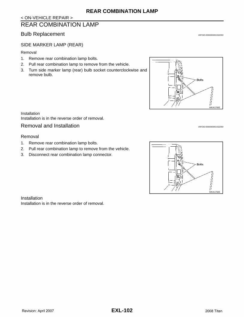
REAR COMBINATION LAMP
< ON-VEHICLE REPAIR >REAR COMBINATION LAMP
Bulb Replacement INFOID:0000000001532093
SIDE MARKER LAMP (REAR)
Removal
1. Remove rear combination lamp bolts.2. Pull rear combination lamp to remove from the vehicle.3. Turn side marker lamp (rear) bulb socket counterclockwise and
remove bulb.
InstallationInstallation is in the reverse order of removal.
Removal and Installation INFOID:0000000001532094
Removal1. Remove rear combination lamp bolts.2. Pull rear combination lamp to remove from the vehicle.3. Disconnect rear combination lamp connector.
InstallationInstallation is in the reverse order of removal.
WKIA1760E
WKIA1760E
EXL-102

SERVICE DATA AND SPECIFICATIONS (SDS)
C
D
E
F
G
H
I
J
K
M
A
B
XL
N
O
P
< ON-VEHICLE REPAIR >
E
SERVICE DATA AND SPECIFICATIONS (SDS)
Headlamp INFOID:0000000001396334
*: Always check with the Parts Department for the latest parts information.
Exterior Lamp INFOID:0000000001396335
*: Always check with the Parts Department for the latest parts information.
Item Wattage (W)*
Low 51/55
High 60/65
Item Wattage (W)*
Front combination lampTurn signal/parking lamp (front) 27/8
Side marker (front) 3.8
Rear combination lamp
Stop/tail lamp 27/7
Turn signal lamp 27
Back-up lamp 16
Cargo lamp (tailgate) 16
Fog lamp 37.5
License plate lamp 5
High-mounted stop lamp 12.8
Side turn signal LED
Puddle lamp 8
EXL-103