drinking water treatment using air · pdf filepresentation overview • us drinking water...
TRANSCRIPT

Drinking Water TreatmentUsing Air Strippers
Dave FischerDave FischerQED Environmental Systems Inc.Ann Arbor, MI / San Leandro, CA
Copyright © QED Environmental Systems, Inc. 2007- 2011; all rights reserved.

Presentation Overview
• US Drinking Water SourcesVOCs in Public Water Supplies• VOCs in Public Water Supplies
• VOC Treatment Methods• Air Stripping and Types of Air StrippersAir Stripping and Types of Air Strippers• QED E-Z Tray®
• The QED Air Stripper Modelerpp• Process Requirements• THM Removal• Ammonia, H2S, Radon and Methane• Case Studies

Drinking Water Sources
• 52,000 of the 156,000 public drinking water systems in thedrinking water systems in the United States are defined as “community water systems” (CWS)community water systems (CWS)
• 92% of the US population receive their water from a CWS
• 40,600 or 80% obtain part or all of their water from groundwater supply wells

VOCs in Public Water SuppliesChloroform
Methyl tert-butyl ether (MTBE)Perchloroethene (PCE)Perchloroethene (PCE)
BromoformDibromochloromethaneTrichloroethene (TCE)
BromodichloromethaneBromodichloromethane1,1,1-Trichloroethane (TCA)
1,1-Dichloroethane (1,1-DCA)Dichlorodifluoromethane (CFC-12)
cis-1,2-Dichloroethene (cis-1,2-DCE), ( , )1,1,-Dichloroethene (1,1-DCE)
Trichlorofluoromethane (CFC-11)Trans-1,2-Dichloroethene (trans-1,2-DCE)
Toluene
DETECTION FREQUENCY IN PERCENT

“Traditional” Treatment Methods
• Filtration with granular activated carbon (GAC)• Chemical treatment systemsChemical treatment systems• Biological treatment methods
R d ti f THMReduction of THMs
• Reducing organic carbon prior to disinfection• Alternate disinfectant (e.g., ozone)• Removal of THMs downstream

Air StrippingA process that removes or “strips” volatile organic compounds from contaminated water by contacting clean air with
t i t d tcontaminated water across a high surface area, causing the volatile compounds to move fromcompounds to move from the water into the air.
Process is governed by H ’ LHenry’s Law.
Driving dissolved volatile organic contaminants fromorganic contaminants from water into air.
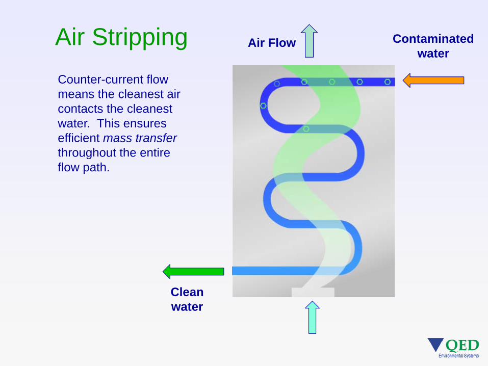
Air Stripping Air Flow Contaminated water
Counter-current flow means the cleanest air
t t th l t
water
contacts the cleanest water. This ensures efficient mass transfer throughout the entire oug ou e e eflow path.
Clean water

Air Stripping
Air water contact happens in the active tray areas. yHigh air to water surface for transfer is created by the turbulent froth mixture.

Air Stripping
The froth in action.

Air Stripping
T t ff t th hi h
Some physical elements
• Temperature affects the process – higher temperature = better stripping
• Process temperature is roughly equal to water• Process temperature is roughly equal to water temperature; air temperature not a big factor
• Freezing is not a concern for continuous operationFreezing is not a concern for continuous operation
• Discharged air is saturated (high humidity) at the process temperature, so consider condensation and thermal impacts if air treatment is planned

Air Stripping Methods
Simple Storage Tank Aeration• Simple Storage Tank Aeration• Tower Strippers• Stacking Tray Strippers• Sliding Tray Stripper (QED E-Z Tray)g y pp ( y)
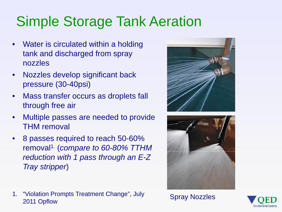
Simple Storage Tank Aeration• Water is circulated within a holding
tank and discharged from spray lnozzles
• Nozzles develop significant back pressure (30-40psi)
• Mass transfer occurs as droplets fall through free air
• Multiple passes are needed to provide p p pTHM removal
• 8 passes required to reach 50-60% removal1. (compare to 60-80% TTHM ( preduction with 1 pass through an E-Z Tray stripper)
Spray Nozzles1. “Violation Prompts Treatment Change”, July 2011 Opflow
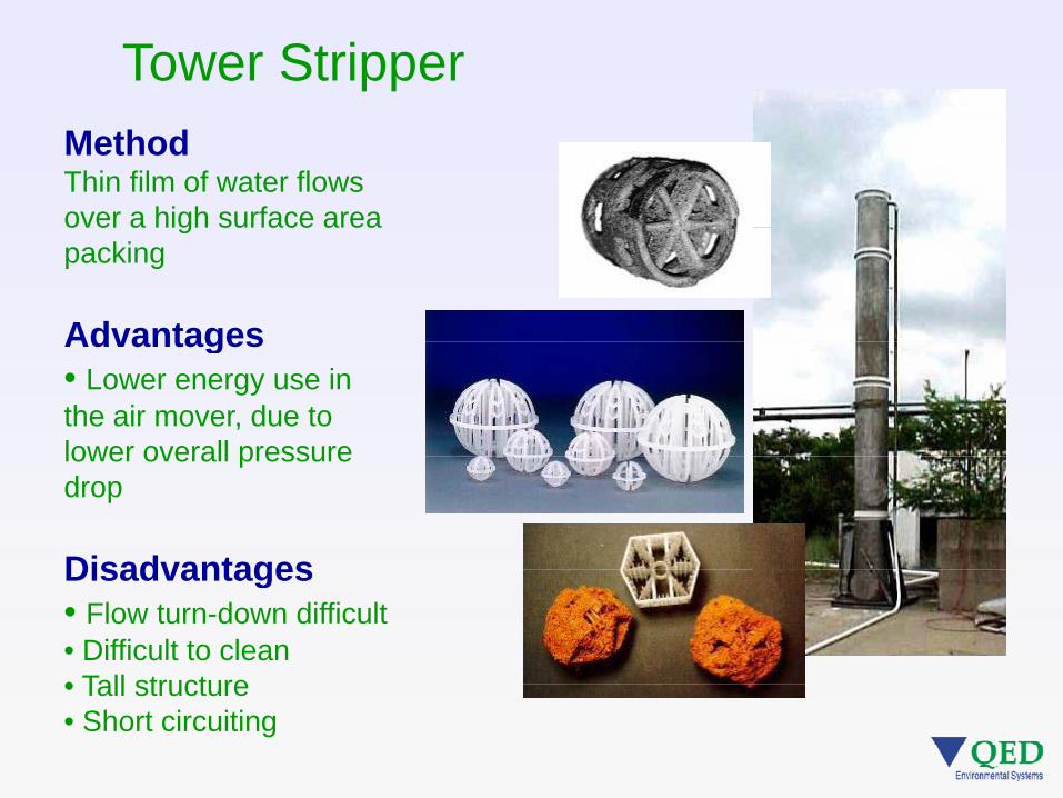
Tower StripperMethodThin film of water flows over a high surface area gpacking
AdvantagesAdvantages• Lower energy use in the air mover, due to lower overall pressurelower overall pressure drop
DisadvantagesDisadvantages• Flow turn-down difficult• Difficult to clean• Tall structure• Tall structure• Short circuiting
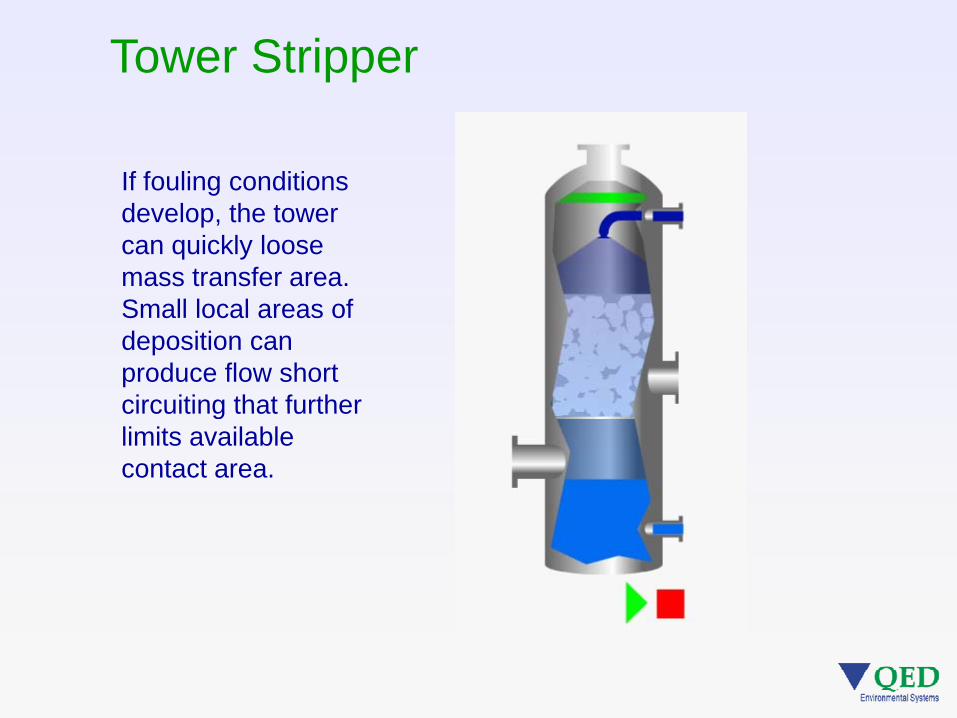
Tower Stripper
If fouling conditions d l th tdevelop, the tower can quickly loose mass transfer area. Small local areas ofSmall local areas of deposition can produce flow short circuiting that furthercircuiting that further limits available contact area.

Tower Stripper vs. Tray Stripper• Biggest issue is cleaning -towers are hard to access and often require flooding with acid solution; high O&M costs• Very tall structure - wind loading, thermal issues, unsightly in some locationsunsightly in some locations• Operating conditions difficult to observe
C l d i• Complex design process due to structural issues• No web based performance pmodel, models harder to use

E-Z Tray® vs. Tower O&M Example• Site in Sturgis, MI treating 250 GPM water containing:
1 1 1 t i hl th1,1,1-trichloroethanec-1,2-dichloroethylenehexachlorobutadienemethylene chlorideynaphthalenetetrachloroethylene (PERC,PCE)trichloroethylene (TCE)
• Oversized tower replaced with a 500 GPM E-Z Tray
• Historical tower cleaning with acid cost about $54 000/year• Historical tower cleaning with acid cost about $54,000/year
• Pressure washing the E-Z Tray every 40-50 days estimated at $8,000/year$ , y
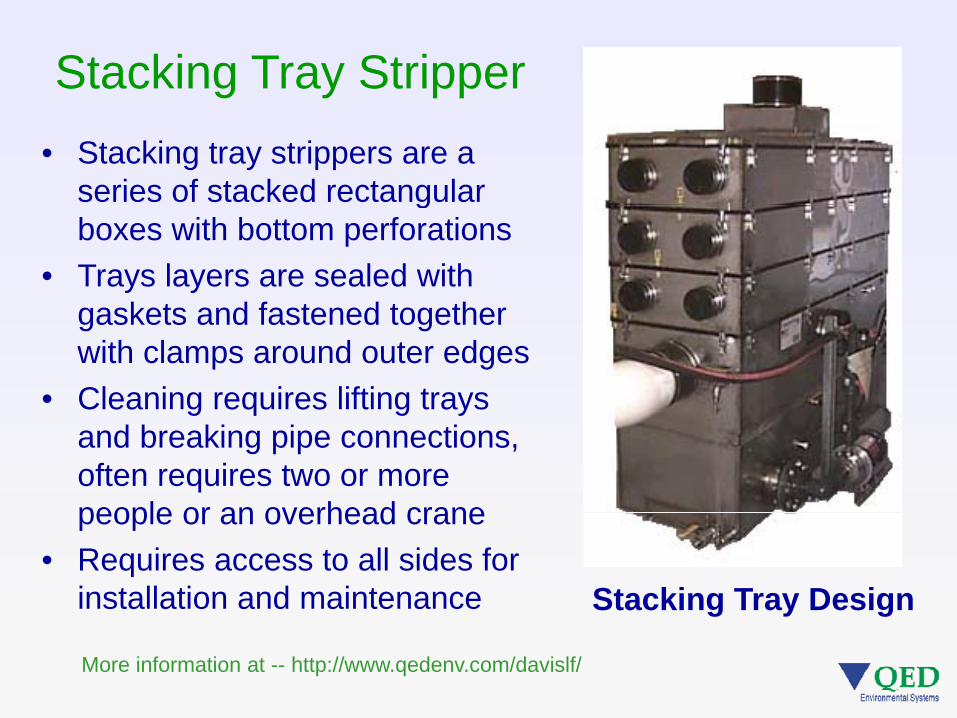
Stacking Tray Stripper• Stacking tray strippers are a
series of stacked rectangular gboxes with bottom perforations
• Trays layers are sealed with k t d f t d t thgaskets and fastened together
with clamps around outer edges• Cleaning requires lifting trays g q g y
and breaking pipe connections, often requires two or more people or an overhead crane
Stacking Tray Design
people or an overhead crane• Requires access to all sides for
installation and maintenance g y g
More information at -- http://www.qedenv.com/davislf/
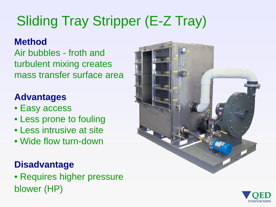
Sliding Tray Stripper (E-Z Tray)MethodAir bubbles - froth and turbulent mixing creates mass transfer surface area
Advantages• Easy access• Less prone to fouling• Less prone to fouling• Less intrusive at site• Wide flow turn-down
Disadvantage• Requires higher pressure• Requires higher pressure blower (HP)

E-Z Tray® Advantages … Cleaning
E-Z Tray Tower Stacking TrayAir Strippers Air Strippers Air Strippers----------------------------------------------------------------------------------------------------
• Single person cleaning(Tray weight is 24 3 lb )
• Packing access and removal is
• Major disassembly and multi person crew
24-73 lbs) difficult needed

E-Z Tray® Advantages … Footprint
E-Z Tray Tower Stacking TrayAir Strippers Air Strippers Air Strippers----------------------------------------------------------------------------------------------------• Reduced footprint
for installation and maintenance
• Small footprint but very tall structure often required
• Lots of space needed for disassembly, lifting from all sides, pipe disconnection anddisconnection and tray stage stacking
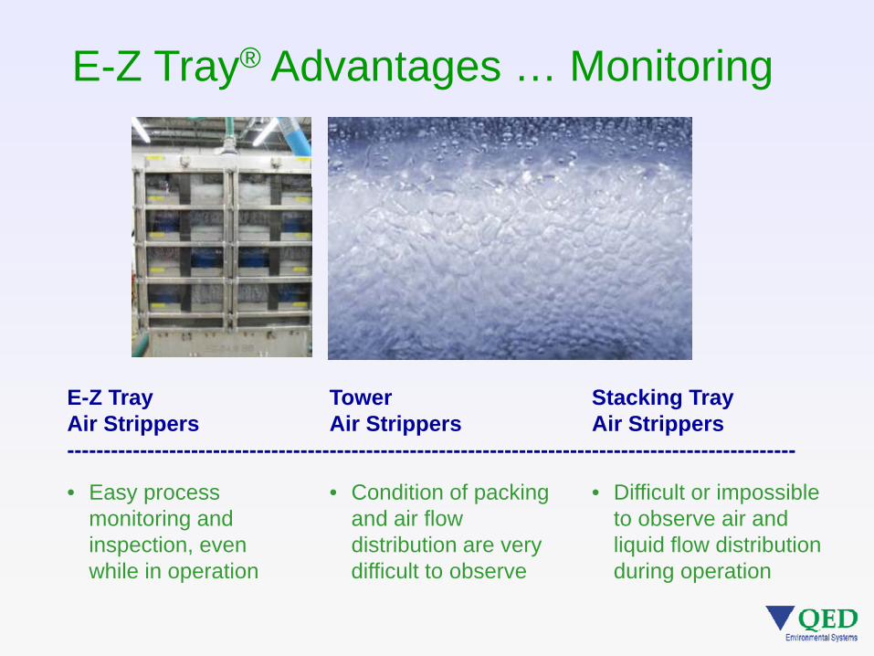
E-Z Tray® Advantages … Monitoring
E-Z Tray Tower Stacking TrayAir Strippers Air Strippers Air Strippers----------------------------------------------------------------------------------------------------
• Easy process monitoring and inspection, even
• Condition of packing and air flow distribution are very
• Difficult or impossible to observe air and liquid flow distribution
while in operation difficult to observe during operation

E-Z Tray® Advantages … Modeling
E-Z Tray Tower Stacking TrayAir Strippers Air Strippers Air Strippers----------------------------------------------------------------------------------------------------
• Easily modeled online by customer to help process
• More complex design process due to structural aspects,
• Online modeler not offered
evaluation assistance normally required

E-Z Tray® Design
One piece shell with single gasketed door cuts down ongasketed door cuts down on possible air leaks
Clear front door gives easy visual check of air stripper performancep
Front access cleaning means piping stays put no need topiping stays put – no need to break connections

Ancillary Equipmenty q p
• Pressure Switch• Skid
• Liquid Flow Meter
• Air Flow Meter
• Blower
• Infeed Pump
• Bag Filters
• Solenoid Valve
• Discharge Pump
• Gravity Drain • Solenoid Valve
• Tank
• Gravity Drain
• Control Panel
• Level Switches

QED Air Strippers
E-Z Tray E-Z Tray E-Z Tray E-Z TrayyModel 6.4
yModel 16.4
yModel 24.4
yModel 96.6

Modeling the ProcessWeb based Modelhttp://www.qedenv.com/modeler
Xin = aqueous concentration entering the air stripperXout = aqueous concentration exiting the air stripperYin = gas concentration entering the air stripperNth = number of theoretical trays in the air stripper The performance modeler is based on the designNth = number of theoretical trays in the air stripperS = stripping factorKh = Henry’s Law constantL = liquid flow rateG = gas flow rate
The performance modeler is based on the designprocedure discussed in -- Kibbey, T. C. G., K. F. Hayes andPennell, K.D., ‘‘Application of Sieve-Tray Air Strippers tothe Treatment of Surfactant-Containing Wastewaters’’,AIChE Journal, Vol. 47, No. 6, June 2001. Also -- Perry, R.H., and D. W. Green, Perry’s Chemical Engineer’s Hand-book, 7th ed., McGraw-Hill, New York 1997.

Henry’s Constant (H)Larger H = more easily stripped (atm/mol frac)Larger H = more easily stripped (atm/mol-frac)
• vinyl chloride - 1245• TCE – 648
• MTBE - 32• acetone - 2 4TCE 648
• benzene - 309acetone - 2.4

2 – Other Information
Process Variables
• Temperatures (air and water)• Altitude (air density)• Flow rates (air and water)• Flow rates (air and water)
- Process impacts- Hydraulic impacts

3 – Pick a Stripper
• First pass – pick the stripper model that matches project flowproject flow
Metric units available on Model Site
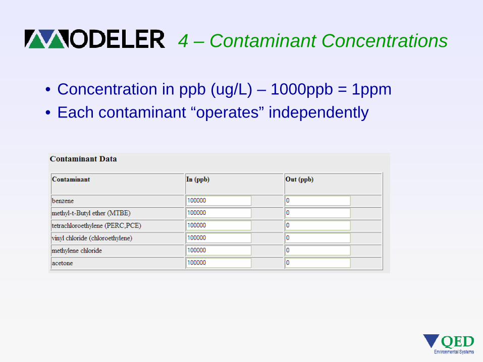
4 – Contaminant Concentrations
• Concentration in ppb (ug/L) – 1000ppb = 1ppm• Each contaminant “operates” independently
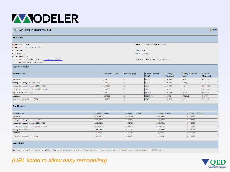
(URL listed to allow easy remodeling)

Successful Process Requirements• Dissolved volatile organics
in a water matrix• No free-phase organics• Clean air (concentration gradient
driven)driven)• High surface area of contact
between air and water• High air to water ratio• Sufficient contact time• No surfactants or other H lowering
Impact of dirty air – less “driving force” for mass transfer
Clean air Contaminated air
• No surfactants or other H lowering factors (dissolved polar organics)
• Stripper is level

Stripper Performance ImpactsStripper Performance Impacts
• Air flow restrictions• Air flow restrictions• Liquid flow issues• Major water/air temperature changes• Major water/air temperature changes• Free phase product or other sorptive
compounds that decrease strippingcompounds that decrease stripping• Surfactants or other polar organic chemicals
that can lower H for target organicsthat can lower H for target organics

Free Phase Product • Coats walls• Residual source in sumpp• Partitioning issues• Interferes with
performance in an unpredictable way

Surfactants / Polar Organics
• Lower effective H for all contaminants due to solubilization of organic compounds by surfactant micelles.C f i• Can cause foaming
– Sometimes subtle (and not required when polar organics are present)
– Demister fouling and blower back-pressure increase– Control = Anti-foam additives (does not recover stripping
effectiveness )– Control = Knock-out tank prior to demister

Surfactants Example
Normal froth Surfactant impacted froth

Types of Tray Air Stripper FoulingTypes of Tray Air Stripper Fouling
• Metal oxides1.Metal oxides• Hardness (scale)• Suspended solidsSuspended solids• Bio solids, slimes• Oils & Greases• Oils & Greases• Free phase non-
aqueous phaseaqueous phase liquids (NAPL)
1. CO2 stripping can cause a slight pH increase, leading to insoluble metal oxide formation

Tray Fouling – Knowing When to Clean
Normal stripper sump pressure = 4-6 inch H2O / tray stage

Tray Fouling - Preventative Measures• Clean trays
– Backup tray set
y g
p y• Sequestering agents
(decrease cleaning frequency)q y)
– inorganic polyphosphates
• Bio-foulingBio fouling– Ozone, etc.
• pH adjustmentI / t– In/out
• Pre-stripper oxidation and filtration for severe cases

Stripper CleaningStripper Cleaning• Cleaning frequency and effort is highly site-g q y g y
specific• Example -
– 1000ppm TDS, 260ppm total hardness, 0.03ppm iron - stripper requires cleaning every 3 weeks
Ti l E Z T i• Time to clean an E-Z Tray stripper– Two 1000gpm, E-Z Tray 96.6 units (8 doors, 48
trays) takes 8-10 minutes/tray to fully removetrays) takes 8-10 minutes/tray to fully remove, pressure wash and reinstall all the trays in this system

THM Removal
• Trihalomethanes (THMs) can form in drinking water h di i f t t ( hl i ) b k dwhen disinfectant (chlorine) breaks down precursor
organic compounds, normally organic solids• Air stripping is an effective way to reduce THMsAir stripping is an effective way to reduce THMs• THMs can re-form after stripping if organic precursors
are still available

THM Removal
Henry’s Law predicts that the THM compounds will strip in the following order:the following order:
Chloroform - easiest to stripBromodichloromethane
Parameter H (atm/mol-frac)benzene 309.2chloroform 225.2Bromodichloromethane
DibromochloromethaneBromoform - hardest to strip
bromodichloromethane 63.1dibromochloromethane 44.4MTBE 32bromoform 29.5
Haloacetic Acids (HAAs) are not removed by air stripping

THM Removal – Some Pilot Data
58.092
Percent THM reduction vs. Water Temperature
QED working with a partner company to
52.0
54.0
56.0
58.0
89909192
mp.
(F)
cent
pconduct THM removal studies at several small
46.0
48.0
50.0
85868788
Wat
er T
em
Percdrinking water
treatment facilities. Results show
11 11 1140.0
42.0
44.0
82838485
consistent THM removal of 85% or more.
11-2 11-3 11-4 11-5 11-9 11-11
11-17
11-23 12-1
% THM Reduction 90 91 90 90 88 86 88 85 84Water temp. 55.4 55.2 54.5 52.8 52.0 52.6 49.6 50.5 42.8

Chloroform Removal
45
THM Removal
30
35
40
20
25
30
CHCl3 in CHCl3 out In – 24 hour Out – 24 hour
Chl
orof
orm
(ppb
)
5
10
15C
0 5 10 15 20 25 30 350
Time (days)

Dibromochloromethane Removal
25
THM Removal
20
25
10
15 DBCM in DBCM out In – 24 hour Out – 24 hour
DB
CM
(ppb
)
5
0 5 10 15 20 25 30 350
Time (days)
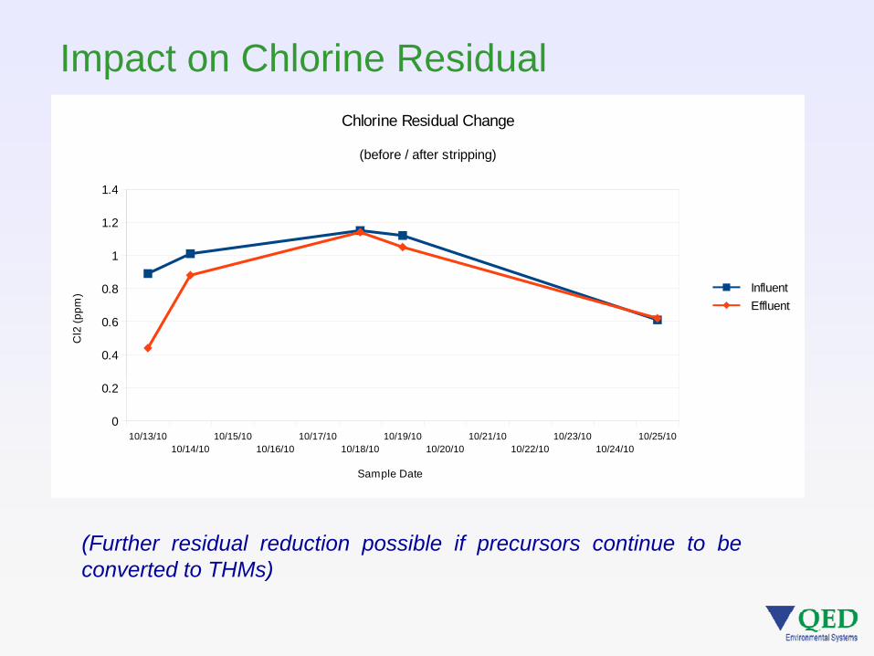
Impact on Chlorine Residual
1 4
Chlorine Residual Change
(before / after stripping)
1
1.2
1.4
0.4
0.6
0.8 Influent Effluent
Cl2
(ppm
)
10/13/1010/14/10
10/15/1010/16/10
10/17/1010/18/10
10/19/1010/20/10
10/21/1010/22/10
10/23/1010/24/10
10/25/100
0.2
Sample Date
(Further residual reduction possible if precursors continue to bet d t THM )converted to THMs)

THM Removal – Process Design
Successful THM removal process design will needsprocess design will needs account for remaining THM precursors, while providing sufficient residual disinfection.
Cl ll l d i tClear well loop design, remote reservoir loop or stripping prior to immediate use may provideto immediate use may provide the best solution.

Pilot Testing
• Prepackaged, just add electricityjust add electricity
• Rental• Used for scale-upUsed for scale up
design• Allows H correction
from results when NAPLs, surfactants, t k t betc. are known to be
presentRental skids available from QED and some equipment contractorsRental skids available from QED and some equipment contractors –contact us for more information.

Additional Site Information for Designg
• Site history of DNAPL and/or LNAPLP t th t h d t t i (DRO t )• Parameters that are hard to strip (DRO, etc.)
• Is O&G above detection limit (is O&G MDL low enough)• Is there air contamination near the blower inlet• Is there air contamination near the blower inlet• Does stable foam form if target water is shaken in a jar• Is there an offset between TOC and the sum of the
target organics• Is there a site history of surfactant use• Are high shear pumps used to capture the water (stable
emulsions of NAPL)

Other Stripper ApplicationsOther Stripper Applications
Ammonia hard to strip• Ammonia – hard to strip • Hydrogen Sulfide – easy to strip
R d l t l t t i• Radon removal – extremely easy to strip• Methane removal – extremely easy to strip

Case Study 1 - NY
• Gasoline spill in high value gresidential area
• Space for process eq ipment limitedequipment limited
• Need for low profile - sound pand appearance
• Strippers housed i t l hi iin metal shipping containers

Case Study 2 - Australia
• Large industrial Li id I
Air Out
chlorinated cleanup • Strippers one component
in a multi-unit / multi-
Liquid In
phase process string• EZ-Tray design allowed
space saving stripper placement
• Strippers used in series for higher removal Liquid Out
Air In
q
Max. plant flow = 4MGD (3000gpm; 15MLD)
Normal operating range = 1.3-1.7MGD (1000-1400gpm)
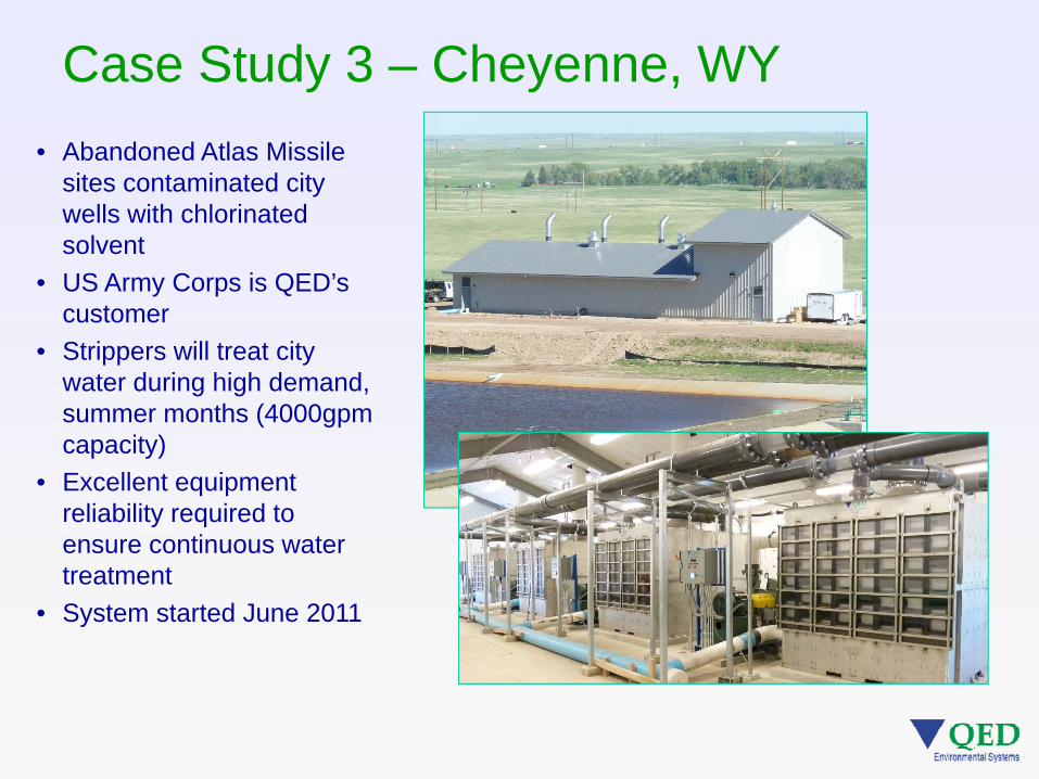
Case Study 3 – Cheyenne, WY• Abandoned Atlas Missile
sites contaminated city wells with chlorinatedwells with chlorinated solvent
• US Army Corps is QED’s customer
• Strippers will treat city water during high demand, summer months (4000gpm capacity)capacity)
• Excellent equipment reliability required to ensure continuous water treatment
• System started June 2011

Summary
• Air strippers are effective at removing dissolved
y
volatile organic compounds from water • The primary process factor is air to water ratio• The process can be modeled using on-line
computer tools -phttp://www.qedenv.com/modeler
• Air stripping equipment needs to be maintained pp g q pto ensure continued design removals

Questions?David Fischer
QED Environmental Systems IncQED Environmental Systems, Inc.
Tel: 800-624-2026E-mail: [email protected]
WEB:WEB:www.qedenv.com