drilling, logging, and sampling of five ... - hmis.hanford.gov
TRANSCRIPT

DOE/RL-2020-26 Rev. 0
5-1
2019 Highlight Retrieval Highlights
• Installed, tested, and began operating the air, water, electrical, and leak detection infrastructure systems required for retrieval of the four AX single-shell tanks (SSTs).
• Completed Tank AX-102 waste retrieval installation and testing in July 2019.
• Single-shell tank AX-102 waste retrieval operations started August 2019, removing 69% (29,000 gal) of the original waste volume (42,000 gal) by calendar year end.
• Removed and disposed of five major long length components to prepare AX-104, AX-103, and AX-101 tanks for waste retrieval system installation, completing equipment removal activities at Tanks AX-104 and AX-103.
• Began installing AX-104 waste retrieval system for planned 2020 operation.
• Removed and disposed of four major long length components to prepare A-Farm tanks for ventilation and waste retrieval system installations.
• Completed A-Farm waste retrieval system design.
• Installed and completed preliminary testing of two new exhausters to ventilate A-Farm SSTs. Final testing and active ventilation of the A-Farm tanks to begin early 2020.
• Using improved equipment and methods, SST C-106 post-retrieval waste volume measured approximately 317 ft3 (9 m3). This meets the Tri Party Agreement (TPA) Appendix H retrieval goal as defined in M-045-00 of 360 cubic feet and provides a path forward for declaring C-106 retrieval completion.
Closure of Waste Management Areas
• Draft DOE O 435.1 Tier 1 (Waste Management Area [WMA] C) and Tier 2 (C-200 Series Tanks) Closure Plans are still under review by the U.S. Department of Energy (DOE).
• Request for Additional Information (RAI) on the Draft Waste Incidental to Reprocessing (WIR) Evaluation for WMA C were received from the Nuclear Regulatory Commission (NRC) in April 2019. A public meeting to review the NRC’s RAIs was conducted in May 2019.
• U.S. Department of Energy, Office of River Protection’s (DOE-ORP) Responses to Requests for
Additional Information on the Draft WIR Evaluation for WMA C were transmitted to NRC in October 2019. A public meeting to review DOE-ORP's responses to the NRC’s RAIs was conducted in October 2019.
• Resolution of Washington State Department of Ecology (Ecology) comments on three of four Hanford Federal Facility Agreement and Consent Order (HFFACO) Performance Assessment (See Appendix I in Attachment 2 – TPA Action Plan) documents related to landfill closure of WMA C has continued while the closure permitting process moves forward.

DOE/RL-2020-26 Rev. 0
5-2
• Resolution of Ecology comments on the Resource Conservation and Recovery Act of 1976 Tier 1 (SST Framework), Tier 2 (WMA C), and Tier 3 (241-C-200 Series Tanks) Closure Plans has continued while the closure permitting process moves forward.
• 241-C-200 Series Tank grout testing resulted in an initial evaluation of grouts used throughout
the DOE complex, the selection and testing of a high-flow grout formula, and initial activities for selection of a bulk fill grout formula.
• Planning for field characterization of the contents of the 241-C-301 Catch Tank continued.
Critical information to support future sampling, retrieval, and closure activities was obtained.
• Drilling, logging, and sampling of five direct push locations for the first WMA A-AX focus area in the area around tanks 241-A-104 and 241-A-105 was completed. Logging of 18 drywells in this focus area were also completed.
• A sampling plan for the second WMA A-AX focus area in the southwestern area of 241 A-Farm was completed and field work was initiated.
Performance Assessments
• The DOE O 435.1 Performance Assessment (RPP-ENV-58782) (i.e., one of the four HFFACO Performance Assessments – See Appendix I in Attachment 2 – TPA Action Plan) for WMA C and the complimentary Draft WIR Evaluation have been undergoing an independent consultative review by the U. S. Nuclear Regulatory Commission as a part of its consultation with DOE on the WIR-related decisions at WMA C.
• The review by the DOE Low-Level Waste Disposal Facility Federal Review Group of (LFRG) the Integrated Disposal Facility Performance Assessment documentation was completed.
• A draft DOE 435.1 Preliminary Performance Assessment (i.e., one of four HFFACO Appendix I
Performance Assessment documents - See Appendix I in Attachment 2 – TPA Action Plan) for WMA A-AX was completed for DOE review.
Interim Surface Barriers • Construction of the three interim surface barrier panel in SX Farm was completed. • Design of an interim surface barrier for TX farm was also completed.
Removal of sludge located at 105-KW Basin.
• Completed transfer of sludge from 105-KW Basin and transported to T-Plant. Plutonium Finishing Plant Demolition
• Low hazard work was completed and final demolition of 234-5Z Building began in 2019.
DOE/RL-2020-26 Rev. 0
5-3
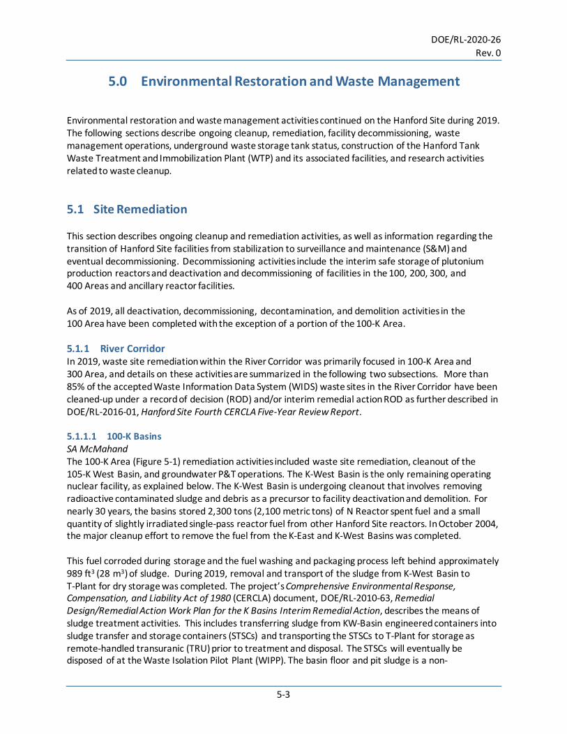
5.0 Environmental Restoration and Waste Management Environmental restoration and waste management activities continued on the Hanford Site during 2019. The following sections describe ongoing cleanup, remediation, facility decommissioning, waste management operations, underground waste storage tank status, construction of the Hanford Tank Waste Treatment and Immobilization Plant (WTP) and its associated facilities, and research activities related to waste cleanup. 5.1 Site Remediation This section describes ongoing cleanup and remediation activities, as well as information regarding the transition of Hanford Site facilities from stabilization to surveillance and maintenance (S&M) and eventual decommissioning. Decommissioning activities include the interim safe storage of plutonium production reactors and deactivation and decommissioning of facilities in the 100, 200, 300, and 400 Areas and ancillary reactor facilities. As of 2019, all deactivation, decommissioning, decontamination, and demolition activities in the 100 Area have been completed with the exception of a portion of the 100-K Area. 5.1.1 River Corridor In 2019, waste site remediation within the River Corridor was primarily focused in 100-K Area and 300 Area, and details on these activities are summarized in the following two subsections. More than 85% of the accepted Waste Information Data System (WIDS) waste sites in the River Corridor have been cleaned-up under a record of decision (ROD) and/or interim remedial action ROD as further described in DOE/RL-2016-01, Hanford Site Fourth CERCLA Five-Year Review Report. 5.1.1.1 100-K Basins SA McMahand The 100-K Area (Figure 5-1) remediation activities included waste site remediation, cleanout of the 105-K West Basin, and groundwater P&T operations. The K-West Basin is the only remaining operating nuclear facility, as explained below. The K-West Basin is undergoing cleanout that involves removing radioactive contaminated sludge and debris as a precursor to facility deactivation and demolition. For nearly 30 years, the basins stored 2,300 tons (2,100 metric tons) of N Reactor spent fuel and a small quantity of slightly irradiated single-pass reactor fuel from other Hanford Site reactors. In October 2004, the major cleanup effort to remove the fuel from the K-East and K-West Basins was completed. This fuel corroded during storage and the fuel washing and packaging process left behind approximately 989 ft3 (28 m3) of sludge. During 2019, removal and transport of the sludge from K-West Basin to T-Plant for dry storage was completed. The project’s Comprehensive Environmental Response, Compensation, and Liability Act of 1980 (CERCLA) document, DOE/RL-2010-63, Remedial Design/Remedial Action Work Plan for the K Basins Interim Remedial Action, describes the means of sludge treatment activities. This includes transferring sludge from KW-Basin engineered containers into sludge transfer and storage containers (STSCs) and transporting the STSCs to T-Plant for storage as remote-handled transuranic (TRU) prior to treatment and disposal. The STSCs will eventually be disposed of at the Waste Isolation Pilot Plant (WIPP). The basin floor and pit sludge is a non-

DOE/RL-2020-26 Rev. 0
5-4
homogenous mixture of debris that includes windblown sand and environmental particulates, concrete fragments from the basin walls, corrosion products from fuel canisters and fuel racks, fuel cladding pieces, tiny pieces of corroded uranium (i.e., uranium oxides, hydrates, and hydrides), ion-exchange resin beads, polychlorinated biphenyls (PCBs), and fission products. Sludge has been defined as any material that is less than or equal to 0.25 in. (0.64 cm) in size.
Figure 5-1. Aerial View of 100-K Area Looking North showing the site as it looked in 2010 on the left
compared to 2019 view on the right.
100-K Area Remediation Progress and Accomplishments (2019) • Completed transfer of sludge from 105-KW Basin engineered containers into 20 STSCs, which were
transported to T-Plant for storage. • An inventory of well-characterized 105-KW Basin sludge samples are being maintained for the site to
enable testing of future treatment options. Conducting alternatives analysis, engineering evaluations, and process development and process/unit operation validation tests will continue these functions as the overall project progresses toward final sludge treatment and disposition.
• The 105-KW Basin floor sample analysis was conducted to help assess the TRU/dose ratio in support of eventual K-West Basin demolition by quantifying the plutonium, americium, and strontium-90 content in K-Basin floor core samples. The cesium is expected to have preferentially exchanged into the concrete/paint layers relative to actinides and strontium. Thus, the high dose of cesium-137 in the concrete/paint surface is not expected to correlate with the TRU content derived from the K-Basin sludge models. The characterization work will generate a new relationship for the concrete floor of K-West Basin between cesium-137, which can be determined from gamma energy analysis and dose correlations, and the TRU and strontium-90 content. These correlations are used to determine the contribution of the concrete walls and floors to the total radioactive material inventory remaining in the basin. This information supports development of waste profiles for the 105-KW basin low-level waste (LLW) demolition rubble that stands to be generated and shipped to Environmental Restoration Disposal Facility (ERDF) for disposal.
• Nuclear Fuel Fragment Specimens (NFFS) were found in the K Basin after containerization of sludge.
This material is expected to be uniquely useful relative to future process testing in phase 2 of the sludge treatment project 2. In fiscal year (FY) 2016, Pacific Northwest National Laboratory (PNNL)

DOE/RL-2020-26 Rev. 0
5-5
developed a plan to receive, repackage, and monitor the NFFS until it is used in Phase 2 testing. Receipt of NFFS is expected to be initiated in FY 2020.
• Continued groundwater pump-and-treat (P&T) operations. In addition to these operations the
following actions were also conducted for the 100-K Area groundwater. ‒ The site completed a study for the 100-K West P&T system and identified a residual hexavalent
chromium source area that is preventing attainment of the groundwater cleanup levels. The P&T system was shut down for a period of time with monitoring of the hexavalent chromium concentration response in the aquifer. Based on the response, an analysis was conducted to estimate source location and strength that would result in the observed increases in chromium(VI) concentration during the rebound period. The results were used to target subsequent source treatment options to minimize the duration of the P&T operations.
‒ Sediments are being analyzed to identify the characteristics of a secondary source to a
chromium plume in the 100-K Area. Collected sediment samples are being analyzed in a suspected chromium source area for a plume in the 100-K Area of the Hanford Site. This analysis will help quantify the geochemical nature of the continuing chromium source and support performance assessment (PA) of soil flushing being applied as a treatability test of potential source treatment. This source characterization and treatment are the remaining elements to be addressed prior to termination of active P&T remediation for this portion of the 100-K Area.
A treatability test was conducted in the 100-K Area at a location that was determined to be a continuing source of hexavalent chromium groundwater contamination. The treatability test used soil flushing, or the application of clean water, to mobilize residual Cr(IV) in the vadose zone, where it continues to produce groundwater contamination above applicable standards, into groundwater where the KWP&T system can remove it to reduce the time required to achieve cleanup goals through mass removal. By the end of calendar year (CY) 2019, the KW infiltration gallery had discharged approximately 43 million gal (163 million L) of water to the soil column near the site of the 183.1-KW Headhouse. • Completed removal of asbestos from the 165-KW Building in preparation for demolition.
• Started removal of the 166-KE fuel oil bunker, which supplied fuel oil to the boilers located
in 165-KE Power Control Building. Removal of the fuel oil bunker will continue into 2020.
• Completed demolition of 1724, 1724-KA, and 167-K Buildings.
• Waste sites 100-K-50:2 and 100-K-94 are interim closed and backfilled.
• Completed excavation and load out of contaminated material for the 100-K-99 waste site. Verification samples have been collected and waiting on results.
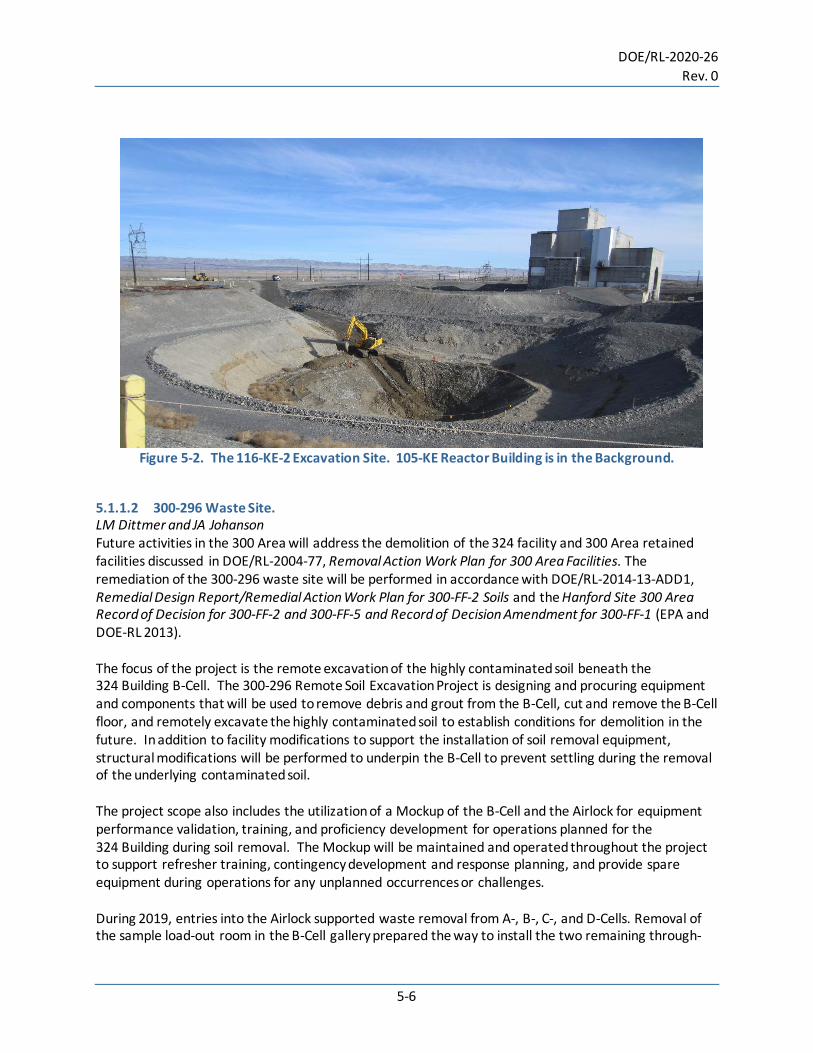
• Excavation of waste sites 116-KE-2 (Figure 5-2) and 100-K-47:1 is ongoing. The overburden soil on the 100-K-47:2 waste site removal was started in 2019 and will continue into 2020. Overburden soil is considered clean and will be used as fill material once the waste sites have been remediated.
DOE/RL-2020-26 Rev. 0
5-6
Figure 5-2. The 116-KE-2 Excavation Site. 105-KE Reactor Building is in the Background.
5.1.1.2 300-296 Waste Site. LM Dittmer and JA Johanson Future activities in the 300 Area will address the demolition of the 324 facility and 300 Area retained facilities discussed in DOE/RL-2004-77, Removal Action Work Plan for 300 Area Facilities. The remediation of the 300-296 waste site will be performed in accordance with DOE/RL-2014-13-ADD1, Remedial Design Report/Remedial Action Work Plan for 300-FF-2 Soils and the Hanford Site 300 Area Record of Decision for 300-FF-2 and 300-FF-5 and Record of Decision Amendment for 300-FF-1 (EPA and DOE-RL 2013). The focus of the project is the remote excavation of the highly contaminated soil beneath the 324 Building B-Cell. The 300-296 Remote Soil Excavation Project is designing and procuring equipment and components that will be used to remove debris and grout from the B-Cell, cut and remove the B-Cell floor, and remotely excavate the highly contaminated soil to establish conditions for demolition in the future. In addition to facility modifications to support the installation of soil removal equipment, structural modifications will be performed to underpin the B-Cell to prevent settling during the removal of the underlying contaminated soil. The project scope also includes the utilization of a Mockup of the B-Cell and the Airlock for equipment performance validation, training, and proficiency development for operations planned for the 324 Building during soil removal. The Mockup will be maintained and operated throughout the project to support refresher training, contingency development and response planning, and provide spare equipment during operations for any unplanned occurrences or challenges. During 2019, entries into the Airlock supported waste removal from A-, B-, C-, and D-Cells. Removal of the sample load-out room in the B-Cell gallery prepared the way to install the two remaining through-
DOE/RL-2020-26 Rev. 0
5-7
support assemblies for the B-Cell remote excavator arms. These entries resulted in the shipment of 8 boxes of mixed LLW, 64 roll off container of LLW, and 32 drums of LLW to ERDF. Cell cleanout continues in A-Cell to make way for equipment installations in the cell, and in B-Cell to access the highly contaminated soil beneath the cell. Debris removal was completed in both C- and D-Cells. Four pilot holes (of 22 micropile borings) were completed in Room 18 adjacent to B-Cell. These borings extend approximately 30 ft (10 m) below the B-Cell floor. They will be filled with grout as part of the structural modifications to provide support to B-Cell during floor removal and remote excavation activities. In November 2019, 324 Building Disposition Project called a Stop Work for the 300-296 Remote Soil Excavation Project due to several contamination events. A Root Cause Analysis was conducted, and a Corrective Action Plan will be developed to provide the project with a path forward to resume project activities. 5.1.1.3 300 Area Waste Sites. Interim stabilization of three waste sites in the 300 Area (300-5, 331-LSLT1, and 331-LSLT2) was completed in 2018. The 300-5 site consists of fuel-contaminated soil from previously removed buried unleaded gasoline and diesel fuel tanks. The 331-LSLT1 and 331-LSLT2 sites are former waste trenches that accepted liquid animal waste. All three of these sites were covered by impermeable barriers to prevent water intrusion into the contaminated soil. These waste sites will be remediated when the remaining 300 Area facilities are deactivated and removed. 5.1.1.4 400 Area SA McMahand and RW Fisher The Fast Flux Test Facility (FFTF) is a formerly operating 400-megawatt (thermal) liquid-metal cooled (sodium) research and test reactor located in the 400 Area (Figure 5-3). Built in the late 1970s, the original mission of the facility was to develop and test advanced fuels and materials and to serve as a prototype facility for future Liquid Metal Fast Breeder Reactor Programs. Other missions were also pursued. FFTF operated from April 1982 to April 1992 and provided the nuclear industry with significant advances in fuel performance, medical isotope production, material performance, and passive and active safety systems testing. The reactor was placed in a standby mode in December 1993. After multiple studies, a decision was made to complete facility deactivation, including removing all nuclear fuel, draining the sodium systems, and deactivating systems and equipment to place the facility in a low-cost, long-term S&M condition, all of which was completed in June 2009. FFTF remains in long-term S&M and routine surveillances are performed annually. The FFTF decommissioning was included in DOE/EIS-0391, Final Tank Closure and Waste Management Environmental Impact Statement for the Hanford Site, Richland, Washington, issued on November 12, 2012. The supplement analysis (DOE/EIS-0391D-SA-01), issued in February 2012, concluded that there were no substantial changes. The DOE issued the final ROD on FFTF decommissioning on December 13, 2013 (78 FR 75913). The decision established that DOE will implement entombment, which will remove all above-grade structures including the reactor building. The below-grade structures, the reactor vessel, piping, and other components would remain in place and be filled with grout to immobilize the remaining radioactive and hazardous constituents. Waste generated from these activities would be disposed at authorized disposal facility. Bulk sodium inventories would be processed at the Hanford Site for use in the WTP.
DOE/RL-2020-26 Rev. 0
5-8
The 437 Building Maintenance and Storage Facility (MASF) is a multi-purpose high bay facility supporting mock-up fabrication, engineering scale testing, and training of operations personnel. The MASF complex consists of a main building and a two-story service wing. The main building is 290 ft (88.4 m) long by 95 ft (29 m) wide and provides approximately 28,000 ft2 (2,604.3 m2) of area for mockup testing and training. Major testing and development that took place in MASF in 2019 included the following: • The Sludge Treatment Project utilized the Engineered Container Retrieval and Transfer System
mockup including K-Basin Test Pool at MASF throughout 2019 to perform training and troubleshooting; the system will remain active until closure of K-Basin.
• K-Basin Garnet Filter Media Retrieval (GFMR) testing, development, and Operations/Construction training. Located at K-Basin are multiple filtration systems that require media removal for final closure. A system was developed, tested, and used for training by Operation and Construction personnel at MASF. Production equipment was then fabricated based on final design from this development effort and is currently being deployed at the K-Basin.
• A Sand Filter system located at the K-Basin will also require media retrieval so similarly, a Sand Filter Media Retrieval System also went through the same process at MASF. The production equipment is currently at MASF for future testing and training.
• The 300-296 (324) Project was supported through tooling development for cell cover block removal.
• The Waste Encapsulation and Storage Facility (WESF) W-135 Project started demolition of existing structure and started assembly of a large mockup cell structure in support of testing and training on remote equipment to support the cesium strontium capsule removal program.
Also at the 400 Area (outside the FFTF Property Protected Area) is a mammoth structure called the Fuels and Materials Examination Facility (FMEF). The FMEF was intended to be a support building for the FFTF and the future Liquid Fast-Breeder Reactor Program, the FMEF was never used in any kind of a nuclear capacity. When the nation abandoned the breeder reactor program, FMEF was also left without a mission and remains unused and largely vacant today. Future activities will address demolition of 400 Area surplus facilities.

DOE/RL-2020-26 Rev. 0
5-9
Figure 5-3. Aerial View of the Fast Flux Test Facility.
5.1.2 Central Plateau MJ Hickey Central Plateau facilities include buildings and waste sites in the 200-East, 200-West, and 200-North Areas. The transition toward decommissioning encompasses surveillance, maintenance, and deactivation activities. The Central Plateau includes about 20 mi2 (52 km2) of land located in the center of the Central Plateau that is designated in the Final Hanford Comprehensive Land-Use Plan Environmental Impact Statement (DOE/EIS-0222-F) and the “Record of Decision for the Hanford Comprehensive Land-Use Plan Environmental Impact Statement” (64 FR 61615) as the Industrial-Exclusive Area. The Industrial-Exclusive Area contains the 200-East and 200-West Areas, used in the past primarily for Hanford Site nuclear fuel processing and currently used for waste management and disposal activities. The Central Plateau also encompasses the CERCLA 200 Area National Priorities List site. The Central Plateau has a large physical inventory of chemical processing and support facilities, tank systems, liquid and solid waste disposal and storage facilities, utility systems, administrative facilities, and groundwater monitoring wells. The DOE/RL-2009-10, Hanford Site Cleanup Completion Framework, defines the path forward for cleanup at the Hanford Site. The framework document defines the main components of cleanup in two main geographic areas — the River Corridor and Central Plateau. Because of the goals established in DOE/RL-2009-10, the Tri Party Agreement (TPA) agencies developed changes to the TPA that reflect the path forward for Central Plateau cleanup. The Central Plateau includes two principal cleanup locations: the Inner and Outer Areas. Table 5-1 shows the crosswalk from 23 source operable units on the central plateau to the 10 source operable units. The Inner Area of the Central Plateau is the projected final footprint region of the Hanford Site. Dedicated to waste management and residual contamination containment, it will remain under federal ownership and control as long as potential hazards exist. Operable units within the Inner Area include those described in the sections below.
DOE/RL-2020-26 Rev. 0
5-10
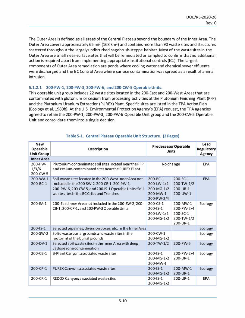
The Outer Area is defined as all areas of the Central Plateau beyond the boundary of the Inner Area. The Outer Area covers approximately 65 mi2 (168 km2) and contains more than 90 waste sites and structures scattered throughout the largely undisturbed sagebrush-steppe habitat. Most of the waste sites in the Outer Area are small near-surface sites that will be remediated or sampled to confirm that no additional action is required apart from implementing appropriate institutional controls (ICs). The largest components of Outer Area remediation are ponds where cooling water and chemical sewer effluents were discharged and the BC Control Area where surface contamination was spread as a result of animal intrusion. 5.1.2.1 200-PW-1, 200-PW-3, 200-PW-6, and 200-CW-5 Operable Units. This operable unit group includes 22 waste sites located in the 200-East and 200-West Areas that are contaminated with plutonium or cesium from processing activities at the Plutonium Finishing Plant (PFP) and the Plutonium Uranium Extraction (PUREX) Plant. Specific sites are listed in the TPA Action Plan (Ecology et al. 1989b). At the U.S. Environmental Protection Agency’s (EPA) request, the TPA agencies agreed to retain the 200-PW-1, 200-PW-3, 200-PW-6 Operable Unit group and the 200-CW-5 Operable Unit and consolidate them into a single decision.
Table 5-1. Central Plateau Operable Unit Structure. (2 Pages)
New Operable
Unit Group Description Predecessor Operable
Units
Lead Regulatory
Agency Inner Area 200-PW-1/3/6 200-CW-5
Plutonium-contaminated soil sites located near the PFP and cesium-contaminated sites near the PUREX Plant
No change EPA
200-WA-1 200-BC-1
Soil waste sites located in the 200-West Inner Area not included in the 200-SW-2, 200-CR-1, 200-PW-1, 200-PW-6, 200-CW-5, and 200-IS-1 Operable Units; Soil waste sites in the BC Cribs and Trenches
200-BC-1 200-LW-1/2 200-MG-1/2 200-MW-1 200-PW-2/4
200-SC-1 200-TW-1/2 200-UR-1 200-UW-1
EPA
200-EA-1 200-East Inner Area not included in the 200-SW-2, 200-CB-1, 200-CP-1, and 200-PW-3 Operable Units
200-CS-1 200-IS-1 200-LW-1/2 200-MG-1/2
200-MW-1 200-PW-2/4 200-SC-1 200-TW-1/2 200-UR-1
Ecology
200-IS-1 Selected pipelines, diversion boxes, etc. in the Inner Area Ecology 200-SW-2 Solid waste burial grounds and waste sites in the
footprint of the burial grounds 200-CW-1 200-MG-1/2
Ecology
200-DV-1 Selected soil waste sites in the Inner Area with deep vadose zone contamination
200-TW-1/2 200-PW-5 Ecology
200-CB-1 B-Plant Canyon; associated waste sites 200-IS-1 200-MG-1/2 200-MW-1
200-PW-2/4 200-UR-1
Ecology
200-CP-1 PUREX Canyon; associated waste sites 200-IS-1 200-MG-1/2
200-MW-1 200-UR-1
Ecology
200-CR-1 REDOX Canyon; associated waste sites 200-IS-1 200-MG-1/2
200-UR-1 EPA
DOE/RL-2020-26 Rev. 0
5-11
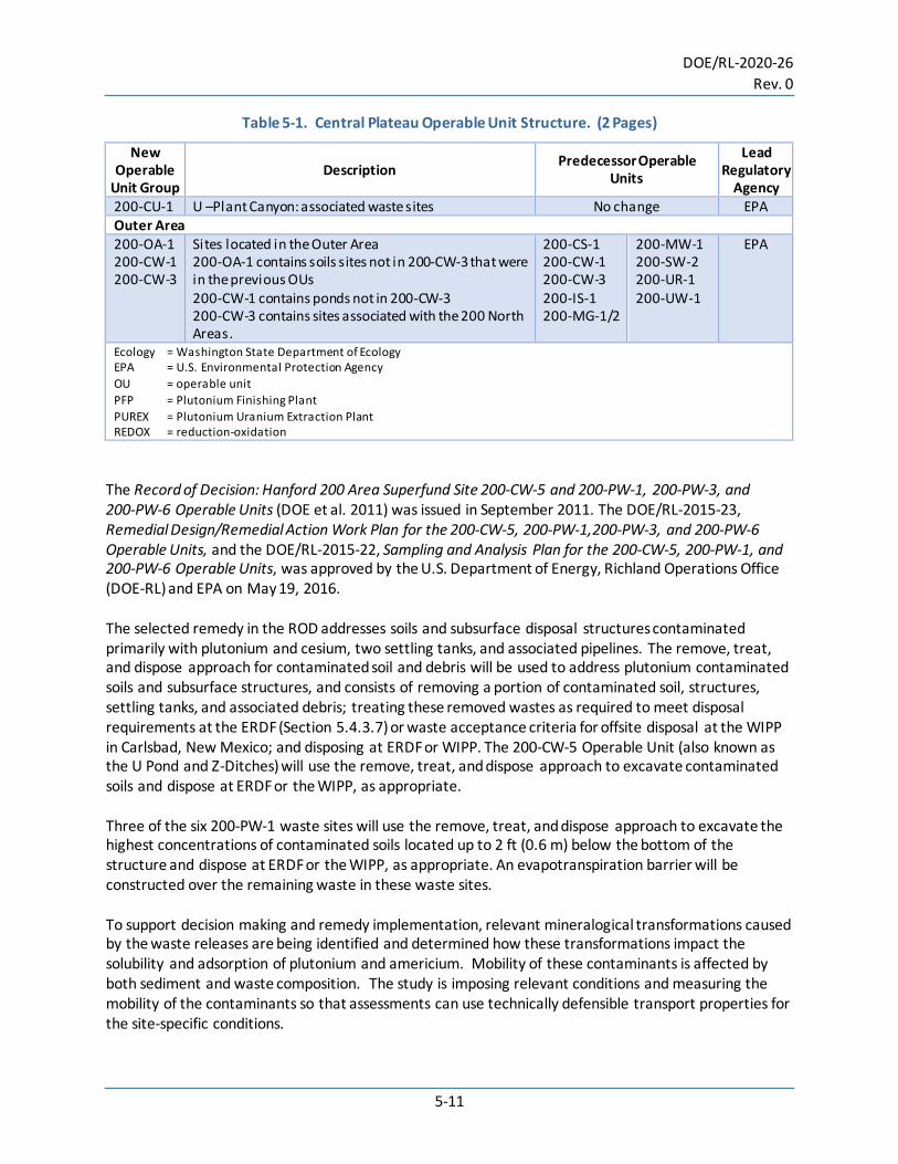
Table 5-1. Central Plateau Operable Unit Structure. (2 Pages)
New Operable
Unit Group Description Predecessor Operable
Units
Lead Regulatory
Agency 200-CU-1 U –Plant Canyon: associated waste sites No change EPA Outer Area 200-OA-1 200-CW-1 200-CW-3
Sites located in the Outer Area 200-OA-1 contains soils sites not in 200-CW-3 that were in the previous OUs 200-CW-1 contains ponds not in 200-CW-3 200-CW-3 contains sites associated with the 200 North Areas.
200-CS-1 200-CW-1 200-CW-3 200-IS-1 200-MG-1/2
200-MW-1 200-SW-2 200-UR-1 200-UW-1
EPA
Ecology = Washington State Department of Ecology EPA = U.S. Environmental Protection Agency OU = operable unit PFP = Plutonium Finishing Plant PUREX = Plutonium Uranium Extraction Plant REDOX = reduction-oxidation
The Record of Decision: Hanford 200 Area Superfund Site 200-CW-5 and 200-PW-1, 200-PW-3, and 200-PW-6 Operable Units (DOE et al. 2011) was issued in September 2011. The DOE/RL-2015-23, Remedial Design/Remedial Action Work Plan for the 200-CW-5, 200-PW-1,200-PW-3, and 200-PW-6 Operable Units, and the DOE/RL-2015-22, Sampling and Analysis Plan for the 200-CW-5, 200-PW-1, and 200-PW-6 Operable Units, was approved by the U.S. Department of Energy, Richland Operations Office (DOE-RL) and EPA on May 19, 2016. The selected remedy in the ROD addresses soils and subsurface disposal structures contaminated primarily with plutonium and cesium, two settling tanks, and associated pipelines. The remove, treat, and dispose approach for contaminated soil and debris will be used to address plutonium contaminated soils and subsurface structures, and consists of removing a portion of contaminated soil, structures, settling tanks, and associated debris; treating these removed wastes as required to meet disposal requirements at the ERDF (Section 5.4.3.7) or waste acceptance criteria for offsite disposal at the WIPP in Carlsbad, New Mexico; and disposing at ERDF or WIPP. The 200-CW-5 Operable Unit (also known as the U Pond and Z-Ditches) will use the remove, treat, and dispose approach to excavate contaminated soils and dispose at ERDF or the WIPP, as appropriate. Three of the six 200-PW-1 waste sites will use the remove, treat, and dispose approach to excavate the highest concentrations of contaminated soils located up to 2 ft (0.6 m) below the bottom of the structure and dispose at ERDF or the WIPP, as appropriate. An evapotranspiration barrier will be constructed over the remaining waste in these waste sites. To support decision making and remedy implementation, relevant mineralogical transformations caused by the waste releases are being identified and determined how these transformations impact the solubility and adsorption of plutonium and americium. Mobility of these contaminants is affected by both sediment and waste composition. The study is imposing relevant conditions and measuring the mobility of the contaminants so that assessments can use technically defensible transport properties for the site-specific conditions.

DOE/RL-2020-26 Rev. 0
5-12
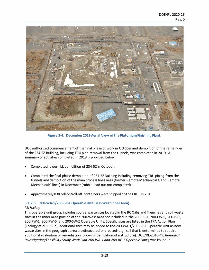
5.1.2.2 200-PW-3 Operable Unit. Also known as the Cesium-137 Waste Group, this operable unit will require additional backfill for three of the five waste sites to achieve coverage of a depth of at least 15 ft (4.57 m). Contamination at the other two waste sites is deeper than 15 ft (4.57 m) from the ground surface and will not require additional backfill. 5.1.2.3 200-PW-6 Operable Unit. This operable unit and three of the six 200-PW-1 waste sites will use the remove, treat, and dispose approach to excavate a significant portion (~90%) of the contaminated soils to a depth of 33 ft (10 m) below ground surface and dispose at ERDF or WIPP, as appropriate. An evapotranspiration barrier will be constructed over the remaining waste at these sites. A soil vapor extraction (SVE) system was used to remove and treat carbon tetrachloride contamination at waste sites in the High-Salt Waste Group. During SVE operations, vapor-phase carbon tetrachloride was extracted through multiple vadose zone wells and adsorbed onto granular activated carbon before the treated, clean vapor was released to the atmosphere. Between 1992 and 2012, the last year of SVE operation, 88.3 tons (80,107 kg) of carbon tetrachloride were removed from the vadose zone. This remedy was evaluated using the process outlined in PNNL-21843, Soil Vapor Extraction System Optimization, Transition, and Closure Guidance, and DOE/RL-2014-18, Path Forward for Future 200-PW-1 Operable Unit Soil Vapor Extraction Operations. In November 2015, EPA concurred that the SVE remedy met the remedial action objectives in the ROD and that SVE activities could be ended. EPA concurrence with the DOE/RL-2014-48, Response Action Report for the 200-PW-1 Operable Unit Soil Vapor Extraction Remediation, in August 2016 closed out the SVE portion of the 200-PW-1 Operable Unit remedy in the ROD and initiated activities to terminate SVE operations and vadose zone monitoring. ICs and long-term monitoring will be required for waste sites in the 200-CW-5, 200-PW-1, 200-PW-3, and 200-PW-6 Operable Units where waste is left in place and unrestricted land use is precluded. 5.1.2.4 Plutonium Finishing Plant Complex. WG Cox The PFP began processing plutonium nitrate solutions into metallic plutonium during 1949 for shipment to nuclear weapons production facilities. Operation of this plant continued into the late 1980s. DOE issued a shutdown order for PFP in 1990. In 1996, DOE-RL authorized the deactivation and transition of plutonium-processing portions of the facility in preparation for decommissioning under a CERCLA non-time critical above-grade removal action. All special nuclear materials and stored fuel elements were removed from the plant and security downgraded by the end of 2009. Work commenced to decommission and demolish the PFP complex to a slab-on-grade condition. Demolition work stopped in December 2017 when contamination was found outside the radiologically controlled area. Stabilization and recovery took the majority of 2018 with lower hazard work authorized to start again in September. Figure 5-4 provides a view of the PFP complex in December 2019.
DOE/RL-2020-26 Rev. 0
5-13
Figure 5-4. December 2019 Aerial View of the Plutonium Finishing Plant.
DOE authorized commencement of the final phase of work in October and demolition of the remainder of the 234-5Z Building, including TRU pipe removal from the tunnels, was completed in 2019. A summary of activities completed in 2019 is provided below: • Completed lower-risk demolition of 234-5Z in October. • Completed the final phase demolition of 234-5Z Building including removing TRU piping from the
tunnels and demolition of the main process lines area (former Remote Mechanical A and Remote Mechanical C lines) in December (rubble load out not completed).
• Approximately 830 roll-on/roll-off containers were shipped to the ERDF in 2019. 5.1.2.5 200-WA-1/200-BC-1 Operable Unit (200-West Inner Area). MJ Hickey This operable unit group includes source waste sites located in the BC Cribs and Trenches and soil waste sites in the Inner Area portion of the 200-West Area not included in the 200-CR-1, 200-CW-5, 200-IS-1, 200-PW-1, 200-PW-6, and 200-SW-2 Operable Units. Specific sites are listed in the TPA Action Plan (Ecology et al. 1989b); additional sites may be added to the 200-WA-1/200-BC-1 Operable Unit as new waste sites in the geographic area are discovered or created (e.g., soil that is determined to require additional evaluation or remediation following demolition of a structure). DOE/RL-2010-49, Remedial Investigation/Feasibility Study Work Plan 200-WA-1 and 200-BC-1 Operable Units, was issued in

DOE/RL-2020-26 Rev. 0
5-14
January 2017. In addition, the U.S. Department of Energy (DOE) obtained approval of DOE/RL-2009-94, 216-U-8 Crib and 216-U-12 Crib Vadose Zone Characterization Sampling and Analysis Plan, which supports the 200-WA-1 Operable Unit remedial investigation. Additionally, the following science and technology efforts were conducted: • Electrical Resistivity Tomography (ERT) to identify waste fluid migration pathways and select
characterization borehole locations at U-Plant site within the 200-WA-1 Operable Unit. ERT is sensitive to changes in subsurface conductivity that are caused by the presence of high ionic strength waste fluids. Thus, the ERT can identify the path of nitrate waste migration in the vadose zone. The identified pathways can then be used to target characterization boreholes to collect contaminated sediment and conduct detailed analyses of contaminant conditions for assessing potential future flux to groundwater.
• An integrated approach for geophysical monitoring and modeling is being established to support implementation and interpretation of characterization data and to design and implement monitoring where needed. Multiple geophysical techniques are available to measure subsurface properties and contamination. New data interpretation approaches (such as E4D) are being applied to improve resolution of data interpretation and to directly link interpretations to computer models. Direct linkage with models enables improved estimates of future contaminant migration and impact to groundwater.
• Future feasibility studies and remedy designs need site-specific guidelines on dust control in the
Central Plateau. A practical guide on selecting and implementing dust control measures is being created as well as an actionable guidance document that clearly outlines the necessary steps in establishing and implementing dust control plans specific to the Central Plateau that comply with federal and state laws.
5.1.2.6 200-EA-1 Operable Unit (200-East Inner Area). This operable unit consolidates the remaining Inner Area source sites in the 200-East Area except for the environmental media underlying tank farm waste management areas (WMAs), landfills in the 200-SW-2 Operable Unit, 200-IS-1 waste sites, PUREX, B-Plant Canyon, and several waste sites with deep vadose zone contamination that are adjacent to WMA environmental media sites. Specific sites are listed in Appendix C to the TPA Action Plan (Ecology et al. 1989b); additional sites may be added to the 200-EA-1 Operable Unit as new waste sites in the geographic area are discovered or created (e.g., soil that is determined to require additional evaluation or remediation following demolition of a structure). The 200-EA-1 Operable Unit uses a comprehensive application of the technical cleanup principles for the Inner Area that is consistent with the 200-WA-1 Operable Unit. Analysis of the waste sites in the 200-EA-1 Operable Unit followed the same pattern as the 200-WA-1 Operable Unit and used the same technical basis documents and comprehensive alternatives evaluation to clearly demonstrate how selected remedies for each waste site fit within the framework of impacts from the entire Inner Area. The unsigned 200-EA-1 work plan was provided to the Washington State Department of Ecology (Ecology) and DOE in September 2019 for signature. The document is waiting for completion of the TPA milestone negotiations so the implementation schedule in 200-EA-1 Chapter 6 can be completed.
DOE/RL-2020-26 Rev. 0
5-15
An evaluation spanning over 20 years of performance for the Prototype Hanford Barrier identified key surface barrier design elements based on this evaluation and identified a cost-effective long-term surface barrier monitoring approach. The barrier monitoring demonstrated effective control of surface water infiltration and identified the key barrier elements important for barrier effectiveness. Based on these data, targeted geophysical techniques were identified that can be cost-effectively used for long-term monitoring of barrier performance. 5.1.2.7 Canyon Disposition Initiative D Singleton The Canyon Disposition Initiative was created to investigate the potential for using the five former chemical separations facilities (B-Plant, T-Plant, U-Plant, PUREX Plant, and Reduction-oxidation [REDOX] Plant) in the 200 Areas as disposal facilities for Hanford Site remediation waste rather than demolishing these canyon buildings. The U-Plant was selected as a pilot project for the Canyon Disposition Initiative. The remaining canyon buildings are to be addressed individually, building on previous canyon disposition work. Due to the concerted effort to remove PFP, no action has been taken on this initiative since 2011. Current CERCLA environmental documents that are being developed are taking in consideration what impacts the scheduled activities will have on the Canyon Disposition Initiative. 5.1.2.8 200-IS-1 Operable Unit. MJ Hickey This operable unit includes select inactive waste transfer pipelines and pipeline components in the 200-IS-1 Operable Unit and soil waste sites in the Inner Area that are not included in the canyon area operable units (i.e., 200-EA-1, 200-WA-1, 200-SW-2) or in the tank farm WMAs. Specific sites are listed in the TPA Action Plan (Ecology et al. 1989b). The TPA agencies agreed to use a coordinated CERCLA remedial action and Resource Conservation and Recovery Act of 1976 (RCRA) corrective action process for cleanup decisions in the pipelines operable unit group. DOE/RL-2010-114, 200-IS-1 Operable Unit Pipeline System Waste Sites RFI/CMS /RI/FS Work Plan, was issued in September 2011. This work plan will be updated to incorporate additional pipelines that have been identified since 2011. 5.1.2.9 200-SW-2 Operable Unit (Burial Grounds). This operable unit includes 24 landfills located in the 200-East and 200-West Areas. Three soil waste sites located within the boundary of one of the burial grounds were added to the 200-SW-2 Operable Unit during restructuring. Specific sites are listed in the TPA Action Plan (Ecology et al. 1989b). Portions of the burial grounds listed in the Hanford Facility Resource Conservation and Recovery Act Permit, Dangerous Waste Portion for the Treatment, Storage, and Disposal of Dangerous Waste (Hanford Site RCRA Permit) (WA7890008967) include treatment, storage, and disposal (TSD) facilities. DOE is working with the Ecology to remove unused areas from the permit scope. The TPA agencies agreed to use a coordinated CERCLA remedial action and RCRA corrective action process for cleanup decisions in the 200-SW-2 Operable Unit. DOE/RL-2004-60, 200-SW-2 Radioactive Landfills Group Operable Unit RCRA Facility Investigation/Corrective Measures Study/Remedial

DOE/RL-2020-26 Rev. 0
5-16
Investigation/Feasibility Study Work Plan, was issued in June 2016. A helicopter radiological survey was completed over the majority of the inner area and a summary report was issued in March 2018. 5.1.2.10 200-DV-1 Operable Unit (Deep Vadose Zone). This operable unit includes 43 soil waste sites located in the Inner Area that were previously located in the 200-TW-1, 200-TW-2, and 200-PW-5 Operable Units. Specific sites are listed in the TPA Action Plan (Ecology et al. 1989b). DOE/RL-2011-102, Remedial Investigation/Feasibility Study and RCRA Facility Investigation/Corrective Measures Study Work Plan for the 200-DV-1 Operable Unit, was approved by Ecology on September 13, 2016. The DOE/RL-2010-89, Long-Range Deep Vadose Zone Program Plan, issued in October 2010, summarizes the state of knowledge about contaminant cleanup challenges faced by the deep vadose zone beneath the Central Plateau and the approach to solving those challenges. Field activities associated with the remedial investigation were completed in 2018. An evaluation of vadose zone remediation technologies was prepared, including a compilation of available site-specific testing information. A thorough review of technologies was conducted, supplementing previous reviews and directly relating technology capabilities to 200-DV-1 Operable Unit contaminant settings. The review specifically considered whether any additional site-specific information was needed prior to consideration of the technology in a feasibility study. Based on this assessment, a number of technologies were identified that need additional laboratory treatability tests. A treatability test plan was prepared and testing has been initiated.
Amendment delivery methods appropriate for Hanford Central Plateau vadose zone sites are being evaluated. Remedy implementation in the vadose zone is difficult because distribution of remedy amendments in an unsaturated setting is more challenging than in aquifers. A review of delivery options examined approaches at other remediation sites and evaluated these delivery options in the context of the Hanford Site vadose zone setting.
Characterization and data interpretation approaches for a contaminated perched water zone were identified by the site. The contaminated perched water zone in the 200-DV-1 Operable Unit is currently being addressed by a P&T approach. However, more information about the perched water zone is needed to optimize the P&T system or to identify supplemental or replacement approaches if P&T cannot meet treatment goals. A sampling and analysis plan was prepared to guide these characterization efforts. Remedy options for Central Plateau sources are limited but are needed to support 200-DV-1 treatability decisions and subsequent feasibility studies for the deep vadose zone and perched water in the Central Plateau, which serve as a long-term contaminant sources to groundwater. The maturation of coupled treatment strategies is being conducted to address the remediation of the complex biogeochemistry of contaminant mixtures in both the vadose and perched water zones. Identification of combined technologies, amendment delivery mechanisms, and combined technology and monitoring approaches are being completed, to provide key indicators for remedy transitions. This information will be used to identify potential treatability tests for the 200-DV-1 Operable Unit. 5.1.2.11 200-CB-1 Operable Unit (B-Plant Canyon). This operable unit includes the B-Plant Canyon Building (221-B) and the WESF (225-B), along with exterior ventilation system components for each structure (e.g., high-efficiency particulate air filters and sand filter) and 17 soil waste sites within the vicinity. Specific sites are listed in the TPA Action Plan

DOE/RL-2020-26 Rev. 0
5-17
(Ecology et al. 1989b); additional sites may be added to the 200-CB-1 Operable Unit as new waste sites in the geographic area are discovered or created (e.g., soil that is determined to require additional evaluation or remediation following demolition of a structure). Waste sites near the B-Plant Canyon currently assigned to the 200-EA-1 and 200-IS-1 Operable Units were reassigned to the 200-CB-1. Cesium and strontium capsules located in the WESF are not included in the scope of the 200-CB-1 Operable Unit. 5.1.2.12 200-CU-1 Operable Unit (U-Plant Canyon). This operable unit includes the U-Plant Canyon Building (221-U) and other structures included in the ROD for the U-Plant Canyon (DOE et al. 2005). The U-Plant Canyon Disposition Initiative is a pilot project for disposition of the five canyon buildings in the 200-East and 200-West Areas. Implementation of the selected remedial action (close in place – partially demolished structure) began in 2009. A final decision is needed for the surrounding waste sites in the 200-WA-1 Operable Unit in order to construct the U-Plant Canyon cap. 5.1.2.13 200-CP-1 Operable Unit (PUREX Canyon). This operable unit includes the PUREX Canyon Building (202-A), PUREX Storage Tunnels (218-E-15 and 218-E-16), exterior components of the ventilation system for each structure (e.g., deep bed filters), and 50 soil waste sites in the vicinity. Specific sites are listed in the TPA Action Plan (Ecology et al. 1989b); additional sites may be added to the 200-CP-1 Operable Unit as new waste sites in the geographic area are discovered or created (e.g., soil determined to require additional evaluation or remediation following demolition of a structure). Sites near PUREX currently assigned to the 200-EA-1 and 200-IS-1 Operable Units have been reassigned to the 200-CP-1 Operable Unit. The 200-CP-1 RI/FS work plan was initiated in February 2020 and is on schedule to submit the Draft A document to Ecology for review in September 2020. 5.1.2.14 200-CR-1 Operable Unit (REDOX Canyon). This operable unit includes the REDOX Canyon Building (202-S), exterior components of the ventilation system (e.g., filters), and 12 soil waste sites located in the vicinity. Specific sites are listed in the TPA Action Plan (Ecology et al. 1989b); additional sites may be added to the 200-CR-1 Operable Unit as new waste sites in the geographic area are discovered or created (e.g., soil that is determined to require additional evaluation or remediation following demolition of a structure). Sites near the REDOX Canyon Building currently assigned to the 200-IS-1 Operable Unit have been reassigned to the 200-CR-1 Operable Unit to facilitate remediation. The 200-CR-1 work plan has not been initiated. 5.1.2.15 200-CW-1, 200-CW-3, and 200-OA-1 Operable Units (Outer Area). Soil waste sites in the Outer Area requiring cleanup are assigned to one of the following three operable units. • 200-CW-1 Operable Unit – Contains ponds used for discharging large volumes of cooling water and
other effluents with low levels of contamination or that were only potentially contaminated. There are 14 sites in the 200-CW-1 Operable Unit including eight ponds and associated sewer lines, control structures, and unplanned releases.
• 200-CW-3 Operable Unit – Contains 16 sites that were associated with operating the 200-North Area, a small complex initially used for temporary storage of spent nuclear fuel and later for storing
DOE/RL-2020-26 Rev. 0
5-18
miscellaneous materials and rail cars. The soil waste sites (e.g., trenches, small ponds, septic tanks, and sewer lines) were cleaned up as part of interim actions conducted from 2005 through 2010.
• 200-OA-1, Operable Unit – Incorporates soil waste sites from several previous operable units (Table 5-1).
DOE/RL-2011-58, 200-CW-3 Operable Unit Interim Remedial Action Report, was issued in September 2011. The summary of waste site remediation activities, cleanup processes, and cost information will support developing a final remedial action for the Outer Area of the 200 Areas’ National Priorities List site. 5.1.2.16 Nonradioactive Dangerous Waste Landfill and Solid Waste Landfill. The Nonradioactive Dangerous Waste Landfill (NRDWL) and Solid Waste Landfill (SWL) are located in the Outer Area and are not included in the operable units described above. The NRDWL is a RCRA-permitted disposal facility for dangerous waste generated at the Hanford Site that was not contaminated with radioactive materials. The NRDWL received dangerous waste from 1975 through 1985, asbestos waste through 1988, and sanitary solid waste in 1976. The SWL is a non-RCRA SWL south of the NRDWL. The SWL received non-dangerous and nonradioactive solid waste including paper, construction debris, asbestos, and lunchroom waste from 1973 to early 1996. The SWL also received up to 1.3 million gal (5 million L) of sewage and 100,000 gal (380,000 L) of garage wash water. Because the NRDWL is a RCRA-permitted TSD site, closure is being managed in accordance with WAC 173-303, “Dangerous Waste Regulations”; the SWL is regulated under WAC 173-350, “Solid Waste Handling Standards.” 5.1.3 Groundwater Remediation Support TM Brouns PNNL is providing scientific and technological contribution to the Hanford Site cleanup mission that enhances credibility and defensibility for cleanup decisions and actions with regulatory and stakeholder acceptance and reduces technical risks to the Hanford Site mission. Overall, PNNL is: • Providing systematic analyses of integrated system and constraints therein to identify and address
technical gaps and operational risks
• Providing scientific and technological solutions to enable the baseline and enabling opportunities for improvement in process efficiency
• Providing independent technical basis for near- and long-term decisions and mission needs
• Reducing technical uncertainties and programmatic/operational risks to support consistency in decision making, technical integration, and resolution of long-term technical issues.
In addition to the waste and source area efforts described above, PNNL is providing scientific and technical support for multiple technical aspects of the groundwater remediation and monitoring efforts for the Hanford Site.

DOE/RL-2020-26 Rev. 0
5-19
5.1.3.1 Remediation Support. Candidate remediation technologies were evaluated in support of the 200-UP-1 Operable Unit ROD-required iodine-129 remedy evaluation. While other contaminants in the 200-UP-1 Operable Unit could be addressed with an existing remedial technology, the iodine-129 contamination required additional evaluation to identify an appropriate remedy. The results are being used to support proceeding with a technical impracticability waiver application for the iodine-129 plume in the 200-UP-1 Operable Unit. A technical basis for a technical impracticability waiver for iodine-129 was provided by PNNL. Relevant parameters and information were compiled to support the TI waiver process, including integrating geochemical process descriptions relevant at the field-scale to identify potential risks for leaving iodine-129 in place. Technical defensibility for assessing attenuation mechanisms for the carbon tetrachloride plume in the 200-ZP-1 Operable Unit is provided by PNNL. A rigorous review was conducted of carbon tetrachloride degradation mechanisms and the types of conditions where these may be relevant to natural attenuation in the 200-ZP-1 Operable Unit aquifer. This review also examined the 200-ZP-1 Operable Unit monitoring data and identified indicators of degradation in the aquifer. Analysis of this information included developing a range of carbon tetrachloride degradation rates that are consistent with the monitoring data. This information is being used by the operable unit to plan remedy optimization activities with respect to the transition from active to passive remediation components. Biofouling constituents were analyzed in new 200-West P&T injection wells being installed in the 200-ZP-1 Operable Unit. Aquifer sediment samples were analyzed for microbial and chemical constituents associated with well fouling in an effort to determine the potential for fouling in the new injection wells. Injection wells returning treated groundwater from the Hanford 200-West P&T facility are becoming fouled over time, decreasing overall injection capacity, which adversely affects operation of the 200-West P&T facility. Potential short- and long-term system performance effects of the 200-West P&T effluent injection impacts to the 200-West aquifer were identified. The development of quantitative conceptual models will determine the impacts of the P&T system on the aquifer and provide performance evaluations of operational changes and aquifer-system injection limits. This work supports remedy optimization efforts and short- and long-term remedy decisions related to multiple operable units within the Hanford Central Plateau. Performance assessment of enhanced remediation being implemented for a uranium source zone in the 300-FF-5 Operable Unit was supported. Real-time monitoring was provided of amendment injection using ERT to assess distribution of phosphate in the targeted portion of the periodically rewetted zone of the 300-FF-5 Operable Unit aquifer. This information supported operational decisions during implementation and provided data used as part of a remedy PA. PNNL conducted the laboratory assessment of sediment samples to quantify the uranium mobility change induced by the phosphate treatment. This information is a key aspect of the PA and role of the enhanced attenuation portion within the overall passive attenuation approach for the plume. 5.1.3.2 Monitoring and Data Analysis Support. Innovative approaches are being identified for using geophysical methods to identify key stratigraphic features that create preferential flow paths impacting contaminant transport and remedy applications. High-transmissivity paleo-channels and the configuration of mud units affect contaminant transport in
DOE/RL-2020-26 Rev. 0
5-20
the 200 Areas of the Hanford Central Plateau, but geologic boreholes only provide data at a single location and the geology in the large distances between boreholes can only be estimated. The geophysical methods identified more continuous subsurface geologic information, providing pertinent input to predictive models of contaminant transport used for decision making. ERT was also demonstrated to be a viable geophysical approach for monitoring potential remediation activities within the perched water aquifer. The effectiveness of subsurface electrodes emplaced within a horizontal well was demonstrated through simulation. The use of horizontal subsurface electrodes, in combination with surface electrodes, significantly improved the ability of ERT to image deep subsurface features and monitor remediation activities, even in the presence of buried metallic pipes and tanks. In support of 100-HR-3 Area plume assessments and remedy closure, a characterization approach is being demonstrated for identifying chromium transport between the upper and lower aquifers. The characterization approach identifies the hydraulic connection between the upper, unconfined aquifer and the lower Ringold Upper Mud because it impacts the selection of an optimal P&T strategy and an appropriate closure strategy for the 100-HR-3 remedy. The approach includes the use of data from existing wells, tracer tests, and geophysical monitoring of the tracer test to identify remediation needs associated with chromium in the lower aquifer. PNNL-Hanford Online Environmental Information Exchange (PHOENIX) continues to provide easy access to a suite of public-facing web-GIS applications that inform decision-making. PHOENIX continues to support monthly updates to the Remediation Dashboard to visually represent the remediation progress of the Hanford Site’s groundwater treatment systems. This tool provides open and transparent access to and visualization of data to facilitate evaluation and communication, furthering public trust and engaging the regulatory and stakeholder communities. PHOENIX enables DOE to communicate cleanup progress and risk reduction as a direct result of cleanup activities. Online decision-support tools (SOCRATES) were created to meet DOE needs for groundwater assessments, real-time remedy support, and P&T exit strategies. The tools provide rapid online access to data and data analytics relevant to contaminant transport and remedy decisions, enabling identification of transition points from active to passive remediation. An additional tool within SOCRATES enables access to real-time geophysical imaging of in situ subsurface amendment delivery, providing critical feedback to field operators to optimize remedy performance. The new tools also enable users to visualize remotely-sensed data and identify elevation changes relevant to waste site management and early response to potential structural collapses. This is accomplished through an automated data acquisition process that provides data at regular frequencies and analytical tools that provide decision support. In addition, remotely sensed data provides seasonal estimates of groundwater base flow to the Columbia River, which can improve predictive simulations that are used to make decisions on waste site remedies, site closure, and long-term protectiveness of human health and the environment. Use of remote sensing data is cost-effective and eliminates the need for manual flux measurements at the groundwater-surface water interface.

DOE/RL-2020-26 Rev. 0
5-21
5.2 Waste Management Activities WE Toebe, KL Chase, SR Myrick, JR Hultman This section provides information regarding Hanford Site liquid and solid waste management. Hanford Site cleanup operations result in the generation of solid wastes that must be evaluated for proper management. Solid wastes are reviewed as required by WAC 173-303-070(3), “Designation of Dangerous Waste,” and are considered dangerous (i.e., hazardous) when the criteria for this classification are met. The radionuclides in solid waste are exempt from evaluation under WAC 173-303-070(3) but are subject to evaluation and categorization as TRU, high-level waste (HLW), or LLW under the Atomic Energy Act of 1954 (AEA). Wastes that contain constituents regulated under both WAC 173-303 and the AEA are classified as mixed wastes. Radioactive and/or mixed wastes are managed in several ways. HLW is stored in large underground single-shell and double-shell tanks (DSTs). LLW typically is stored in tanks or containers. The method used to store LLW depends on the source, composition, and waste concentration. TRU waste is stored in vaults, in storage buildings, on aboveground storage pads, and retrievably buried cribs and vaults. DOE/RL-2018-12, Hanford Site Annual Dangerous Waste Report, lists the dangerous and mixed wastes that are generated, treated, and disposed of onsite or shipped offsite. Dangerous and mixed wastes are treated, stored, and prepared for disposal at several Hanford Site facilities. Dangerous waste generated at the site is shipped offsite for treatment and/or disposal. Some types of dangerous waste, such as used lead–acid batteries and aerosol products (e.g., spray paint), are shipped offsite for recycling. Waste that does not contain hazardous or radioactive substances is non-regulated waste. Historically, non-regulated waste generated at the Hanford Site was disposed onsite. Beginning in 1999, non-regulated waste (e.g., refuse and drummed nonhazardous waste) has been disposed of at municipal or commercial solid waste disposal facilities. Non-regulated waste originates at several areas across the Hanford Site. Examples include construction debris, office trash, cafeteria waste, and packaging materials. Other materials and items classified as non-regulated waste include solidified filter backwash and sludge from the treatment of Columbia River water, failed and broken equipment and tools, air filters, uncontaminated used gloves and other clothing, and certain chemical precipitates (e.g., oxalates). Non-regulated demolition waste from the 100 Area decommissioning projects was buried in situ (in place) or in designated disposal locations on the Hanford Site. Unregulated medical waste is similar to typical household waste consisting of papers and plastics that are categorized as non-infectious. Regulated medical waste is waste that may transmit infection from a virus, bacteria, or parasite to humans. Since 1996, medical waste found at the Hanford Site has been shipped to a commercial medical waste treatment and disposal facility. The Solid Waste Information and Tracking System is a computer database used to track a portion of mixed and radioactive waste at the Hanford Site, primarily non-CERCLA containerized waste managed by CH2M Plateau Remediation Company, Mission Support Alliance, and Washington River Protection Solutions, LLC (WRPS). The database includes all waste necessary for all annual reporting requirements from DOE. The database does not include high-level radioactive waste volumes managed at Hanford Site tank farms. As of December 31, 2019, quantities for both mixed and radioactive wastes generated onsite or received from offsite sources and disposed at the Hanford Site as tracked by the Solid Waste Information and

DOE/RL-2020-26 Rev. 0
5-22
Tracking System database are shown in Tables 5-2 and 5-3. Quantities of dangerous waste shipped offsite as tracked by the database are shown in Table 5-4. All data is current as of December 31, 2019. Solid waste management includes treatment, storage, and disposal of solid waste and nuclear material produced during Hanford Site operations or received back from offsite sources authorized by DOE to ship waste to the Hanford Site (e.g., Perma-Fix Northwest, U.S. Navy). These facilities are operated and maintained in accordance with state and federal regulations and facility permits. The following sections describe specific waste management locations at the Hanford Site.
Table 5-2. Solid Wastea Quantities Generated on the Hanford Site.
Waste Category 2014 2015 2016 2017 2018 2019
Mixed Tons 140 657 609 452 523 571 Metric tons 127 596 552 410 474 518
Radioactive Tons 572 1550 665 828 2680 658 Metric tons 519 1408 603 751 2434 597
a Solid waste includes containerized liquid waste.
Table 5-3. Solid Wastea Quantities Received on the Hanford Site from Offsite Sources.
Waste Categoryb 2014 2015 2016 2017 2018 2019
Mixed Tons 38.4 97.9 105 83.3 118 120
Metric tons
35 88.9 95.3 76 107 109
Radioactive Tons 57 91.4 113 133 130 187
Metric tons
52 82.9 102 121 118 170
a Solid waste includes containerized liquid waste. Solid waste quantities do not include U.S. Navy reactor compartments.
b Total includes Hanford Site-generated waste treated by an offsite contractor and returned as newly generated waste. Includes both low-level radioactive and transuranic waste.

DOE/RL-2020-26 Rev. 0
5-23
Table 5-4. Dangerous Wastea Quantities Shipped Off the Hanford Site.
Waste Category 2014 2015 2016 2017 2018 2019 Containerized (DW Only)
Tons 103 76.8 69.4 68.5 84.5 67.9 Metric
tons 93.4b 69.7b 63.0b 62 76.6 61.6
Containerized (MW Only)
Tons 33.7 65.7 69.7 90.4 56.9 36.6 Metric
tons 30.6c 59.6c 63.2c 82 51.6 33.2
Bulk Solids (DW Only)
Tons 22.1 — 0 0 0 Metric
tons 20.1 — 0 0 0
Bulk Solids (Non-Rad/Non-DW)
Tons — — 0 0 0 Metric
tons — — 0 0 0
Bulk Liquids (DW Only)
Tons 22 — 1 0 0 0 Metric
tons 20 — 1.36 0 0 0
Bulk Liquids (Non-Rad/Non-DW)
Tons — — 0 0 0 Metric
tons — — 0 0 0
Totals Tons 181 142 140 158.9 141.4 104.5
Metric tons
164 129 127 144 128.2 94.8
a Does not include Toxic Substances Control Act waste b Dangerous waste only c Mixed waste (radioactive and dangerous) — = no data met the criteria DW = dangerous waste MW = mixed waste
Facilities are operated on the Hanford Site to store, treat, reduce, and dispose of various types of liquid effluent generated by site cleanup activities. These facilities are operated and maintained in accordance with federal and state regulations and facility permits. The Hanford Site’s waste management facilities are primarily located on the Central Plateau. The 2019 updates for each of these facilities (listed below) are provided in the subsections that follow. • Tank Farms • 222-S Laboratory • Central Waste Complex (CWC) • Waste Receiving and Processing Facility (WRAP) • T-Plant Complex • Canister Storage Building (CSB) • Low Level Burial Grounds • WESF • Integrated Disposal Facility (IDF) • ERDF • Effluent Treatment Facility (ETF) • Liquid Effluent Retention Facility (LERF) • 200 Area Treated Effluent Disposal Facility (TEDF)

DOE/RL-2020-26 Rev. 0
5-24
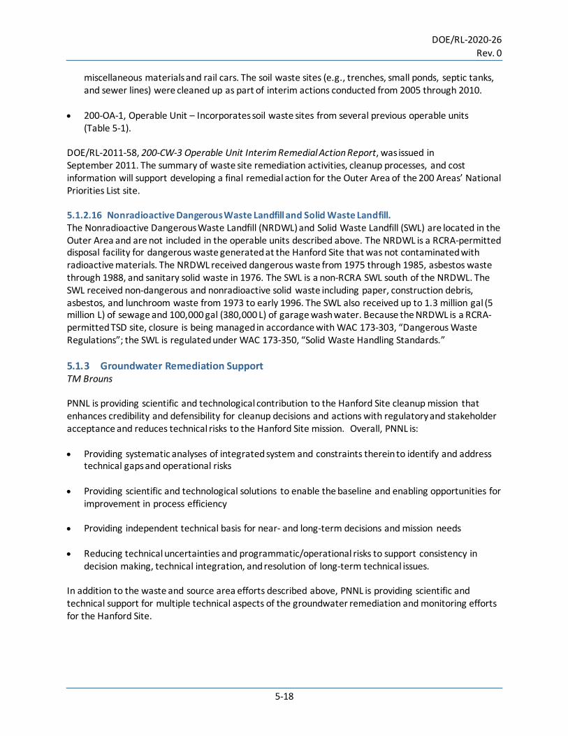
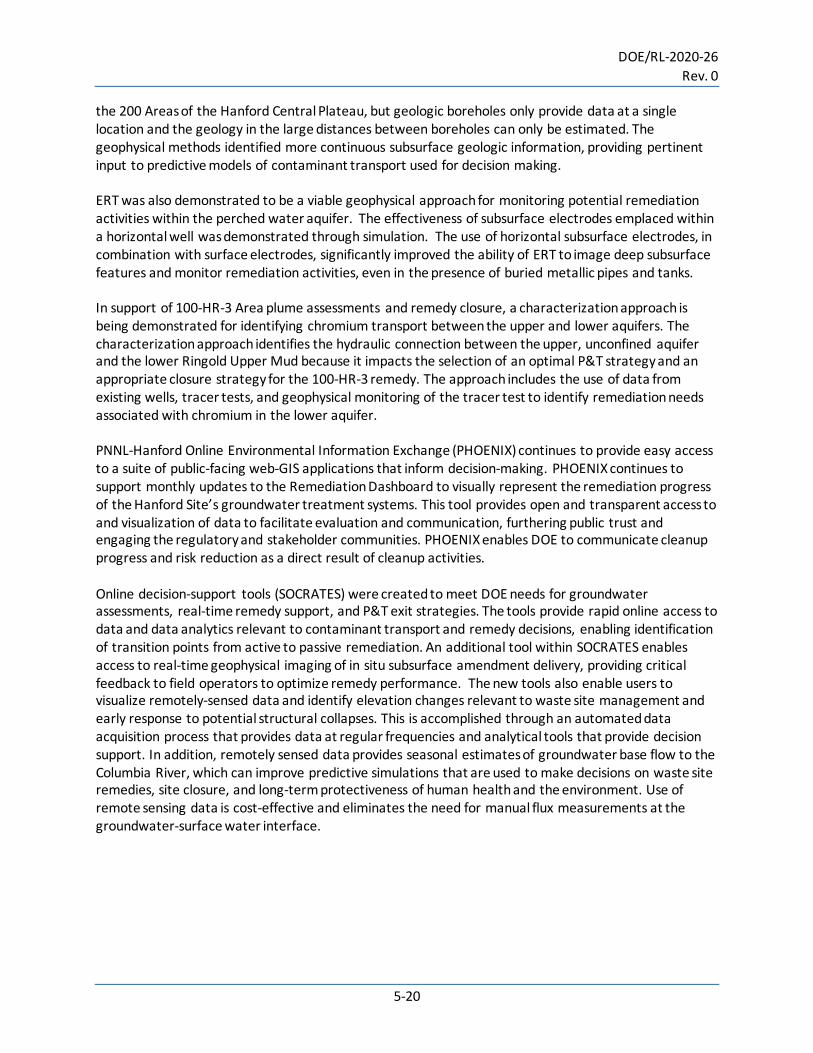
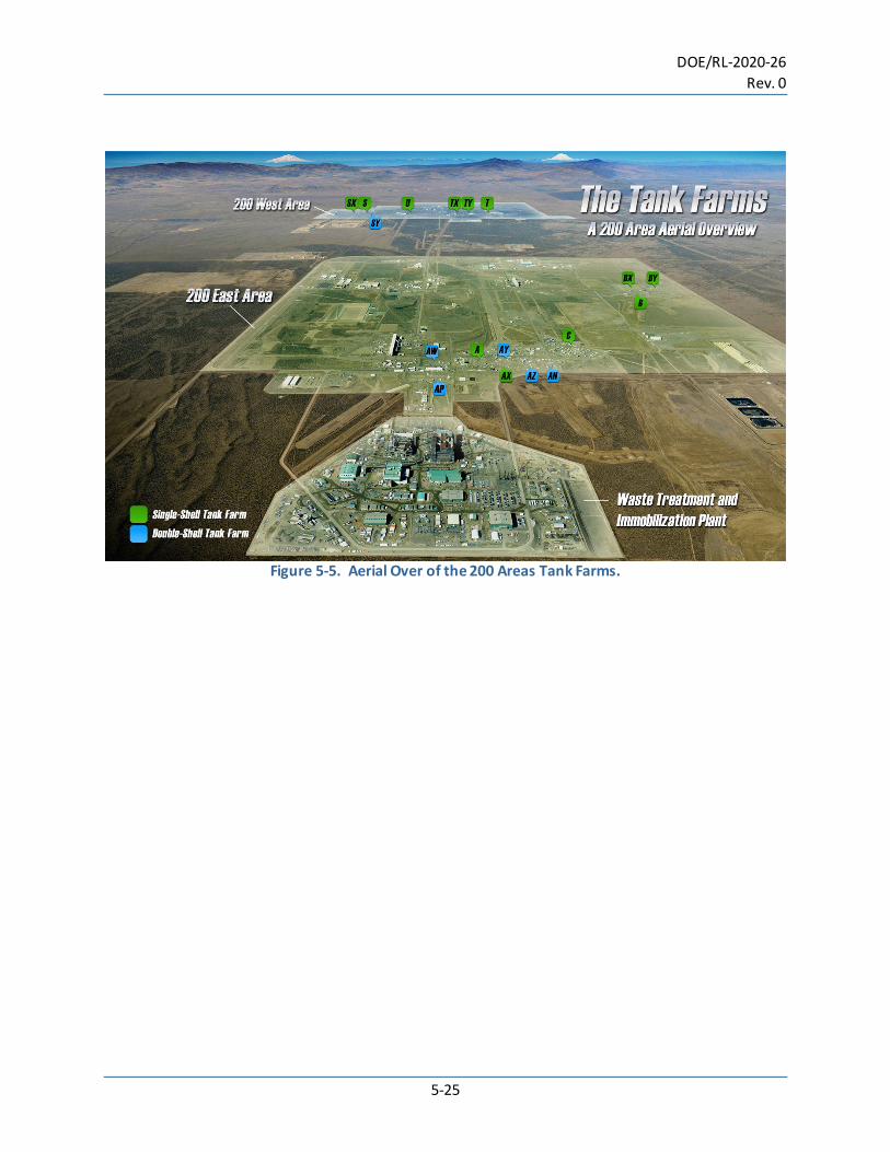
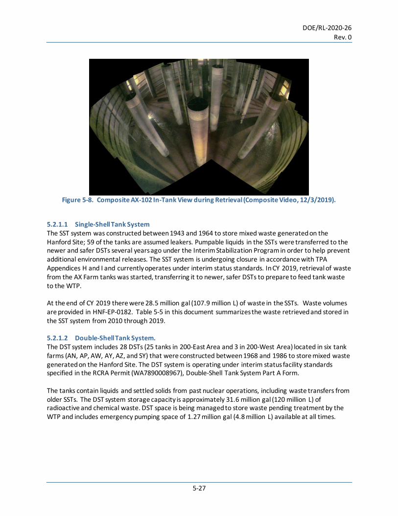
• 242-A Evaporator • WTP. 5.2.1 Tank Farms S Scott, T Brouns Hanford’s 54.1million gal (205.5 million L) of highly radioactive and chemical waste is stored in 177 underground tanks until it is prepared for disposal (Figure 5-5). The tank waste is material left over from years of World War II and post-war production of nuclear weapons. There are 149 single-shell tanks (SSTs) of which retrieval of waste from 16 tanks was declared completed by the end of CY 2019: 15 C-Farm tanks and S-112. At the end of CY 2019 tank C-106 retrieval status was “complete and in review.” S-102 was never declared complete; status is interim stabilized. AY-102 is a DST and was retrieved, inspected and staged for closure per a Settlement Agreement that does not fall under the TPA or Consent Decree for SST retrievals. The SST and DST tanks are grouped into 18 farms in the 200-East and 200-West Areas. This section provides information about the SSTs and DSTs and activities that occurred in CY 2019 related to their operation and closure. The 1998 Hanford Federal Facility Agreement and Consent Order (HFFACO or TPA) established milestones for the retrieval of residual waste solids and interstitial liquids from the 149 aging single-shell tank systems by 2018. In 2010, having completed retrieval of only seven tanks, the DOE and the state of Washington entered into a Consent Decree (Washington v. DOE, Case No. CV-08-5085-FVS (E.D. Wa. October 25, 2010). The Consent Decree established discrete milestones for retrieving 10 C-Farm tanks, and the selection and retrieval of an additional 9 SST. As of FY 2019, 16 tanks have been retrieved under the TPA and Consent Decree: C-101, C-102, C-103, C-104, C-105, C-107, C-108, C-109, C-110, C-111, C-112, C-201, C-202, C-203, C-104, and S-112. Retrieval of tank C-106 has not been declared complete. In 2019, using improved equipment and methods, the C-106 post-retrieval waste volume measured approximately 317 ft3 (9 m3). This meets the TPA Appendix H retrieval goal as defined in milestone M-045-00 of 360 ft3 (9 m3) and provides a path forward for declaring C-106 retrieval completion. Four AX-Farm and five A-Farm SST were selected as the next nine tanks to be retrieved under the Consent Decree (Figure 5-6). Building on C-Farm retrieval lessons learned, an integrated infrastructure system (air, water, electrical, and leak detection) has been installed in AX Farm that will be expanded into A Farm (Figure 5-7). To prepare tanks for installation of waste retrieval equipment, obsolete equipment is removed. Removal efforts are complete for three of the four AX Farm tanks. Installation of the AX-102 waste retrieval system was completed in July 2019 and retrieval operations started in August 2019 (Figure 5-8). By calendar year end, an estimated 69% (~29,000 gal [110,000 L]) of the starting waste volume (~42,000 gal [159,000 L]) had been removed from AX-102 using sluicing and high-pressure water technologies. Installation of the AX-104 waste retrieval system remains ongoing with retrieval operations scheduled to start in mid-2020. The A Farm waste retrieval system design was completed in 2019 and removal of obsolete equipment continues. Two new exhausters were installed and preliminary testing completed in 2019. Final testing and active ventilation of the A Farm tanks will begin in early 2020 improving work and environmental safety.
DOE/RL-2020-26 Rev. 0
5-25
Figure 5-5. Aerial Over of the 200 Areas Tank Farms.
DOE/RL-2020-26 Rev. 0
5-26
Figure 5-6. AX-Farm (Aerial Photograph, January 2020).
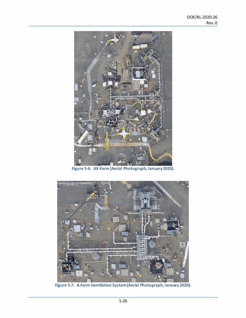
Figure 5-7. A-Farm Ventilation System (Aerial Photograph, January 2020).
DOE/RL-2020-26 Rev. 0
5-27
Figure 5-8. Composite AX-102 In-Tank View during Retrieval (Composite Video, 12/3/2019).
5.2.1.1 Single-Shell Tank System The SST system was constructed between 1943 and 1964 to store mixed waste generated on the Hanford Site; 59 of the tanks are assumed leakers. Pumpable liquids in the SSTs were transferred to the newer and safer DSTs several years ago under the Interim Stabilization Program in order to help prevent additional environmental releases. The SST system is undergoing closure in accordance with TPA Appendices H and I and currently operates under interim status standards. In CY 2019, retrieval of waste from the AX Farm tanks was started, transferring it to newer, safer DSTs to prepare to feed tank waste to the WTP. At the end of CY 2019 there were 28.5 million gal (107.9 million L) of waste in the SSTs. Waste volumes are provided in HNF-EP-0182. Table 5-5 in this document summarizes the waste retrieved and stored in the SST system from 2010 through 2019. 5.2.1.2 Double-Shell Tank System. The DST system includes 28 DSTs (25 tanks in 200-East Area and 3 in 200-West Area) located in six tank farms (AN, AP, AW, AY, AZ, and SY) that were constructed between 1968 and 1986 to store mixed waste generated on the Hanford Site. The DST system is operating under interim status facility standards specified in the RCRA Permit (WA7890008967), Double-Shell Tank System Part A Form. The tanks contain liquids and settled solids from past nuclear operations, including waste transfers from older SSTs. The DST system storage capacity is approximately 31.6 million gal (120 million L) of radioactive and chemical waste. DST space is being managed to store waste pending treatment by the WTP and includes emergency pumping space of 1.27 million gal (4.8 million L) available at all times.
DO
E/RL-2020-26 Rev. 0
5-28
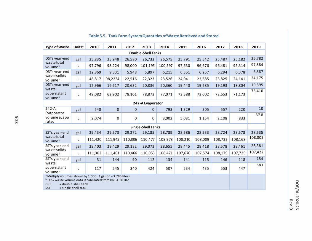
Table 5-5. Tank Farm System Quantities of Waste Retrieved and Stored.
Type of Waste Unitsa 2010 2011 2012 2013 2014 2015 2016 2017 2018 2019 Double-Shell Tanks
DSTs year-end waste total volume b
gal 25,835 25,948 26,580 26,733 26,575 25,791 25,542 25,487 25,182 25,782
L 97,796 98,224 98,000 101,195 100,597 97,630 96,676 96,481 95,314 97,584
DSTs year-end waste solids volume b
gal 12,869 9,331 5,948 5,897 6,215 6,351 6,257 6,294 6,378 6,387
L 48,817 98,2234 22,516 22,323 23,526 24,041 23,685 23,825 24,141 24,175
DSTs year-end waste supernatant volume b
gal 12,966 16,617 20,632 20,836 20,360 19,440 19,285 19,193 18,804 19,395
L 49,082 62,902 78,101 78,873 77,071 73,588 73,002 72,653 71,173 73,410
242-A Evaporator 242-A Evaporator volume evaporated
gal 548 0 0 0 793 1,329 305 557 220 10
L 2,074 0 0 0 3,002 5,031 1,154 2,108 833 37.8
Single-Shell Tanks SSTs year-end waste total volume b
gal 29,434 29,573 29,272 29,185 28,789 28,586 28,533 28,724 28,578 28,535
L 111,420 111,945 110,806 110,477 108,978 108,210 108,009 108,732 108,168 108,005
SSTs year-end waste solids volume b
gal 29,403 29,429 29,182 29,073 28,655 28,445 28,418 28,578 28,461 28,381
L 111,302 111,401 110,466 110,053 108,471 107,676 107,574 108,179 107,725 107,422
SSTs year-end waste supernatant volume b
gal 31 144 90 112 134 141 115 146 118 154
L 117 545 340 424 507 534 435 553 447 583
a Multiply volumes shown by 1,000. 1 gallon = 3.785 liters. b Tank waste volume data is calculated from HNF-EP-0182 DST = double-shell tank SST = single-shell tank
DOE/RL-2020-26 Rev. 0
5-29
A routine visual inspection of the tank AY-102 annulus conducted in August 2012 revealed accumulation of solids in the annular space. It was determined solids were present in the annulus as the result of a leak from the primary tank (RPP-ASMT-53793, Tank 241-AY-102 Leak Assessment Report). AY-102 retrieval operations began in March 2016 with supernatant removal and Sluice Cannon operation (RPP-RPT-59728, Retrieval Completion Status Report for Tank 241-AY-102). On February 15, 2017, following water flushes of the transfer equipment, WRPS notified Ecology “sludge retrieval from 241-AY-102 was completed in accordance with the AY-102 Recovery Project Waste Retrieval Work Plan.” Notification of retrieval completion was provided by letter 17-TF-0021, dated February 23, 2017. At the end of CY 2019, there were 25.8 million gal (97.7 million L) of waste in the DSTs. Waste volumes are provided in HNF-EP-0182. Table 5-5 summarizes the waste retrieved and stored in the DST system from 2010 through 2019. Safe storage, retrieval, and transfer of radioactive waste liquids, salts, and sludge are the primary focus of WRPS. This includes safeguarding the overall integrity of the tanks and tank infrastructure, leak detection, tank life extension, structural analysis, and vapors detection/monitoring, management, and action plan guidance. PNNL is providing technical support for baseline processing, risk reduction, and/or alternative management strategies in a number of key areas. Highlights of 2019 achievements are provided below. • Subsurface Transport Over Multiple Phases – Water-Air-Energy (STOMP-WAE) modeling was
conducted to understand possible pathways for water intrusion into the leak detection system in order to better understand potential causes of secondary liner corrosion. The STOMP-WAE simulator was used to determine the effects of the DST ventilation system on potential water intrusion through construction joints and possible cracks in the concrete dome. The leak detection pits on the DSTs were designed to detect waste leaks in the event of failure of both the primary tank and secondary liners. Many of the leak detection pits are subject to constant ingress of water that shows no evidence of tank waste. The ingress water likely exposes portions of the bottom of the secondary liner to either continuous water exposure or high ambient humidity, both of which increase the risk of corrosion of the bottom of the secondary liner of the DSTs. Identification of temperature effects and seasonal variation in recharge rates provide the technical basis for assessing DST corrosion and risks associated with extending their service life.
• Under-tank nondestructive examination technology capable of delivery to the primary tank bottom of Hanford’s DSTs is being pursued. 2019 achievements included expansion of tank bottom visual inspection deployments through DST refractory air slots as well as continued development of several volumetric inspection technologies. Visual inspections of the primary tank bottom in DSTs was incorporated as a programmatic activity following successful development efforts in 2019. Approximately 3 to 4 inspections are being conducted each year now in parallel to planned ultrasonic testing equipment deployments. Robotic tools built for tank bottom visual inspection underwent design modifications and upgrades through 2019 to accommodate newly developed volumetric inspection sensor packages. These designs are intended to progress through fabrication, testing, and qualification in the 2020/2021 years and be ready for field trials.
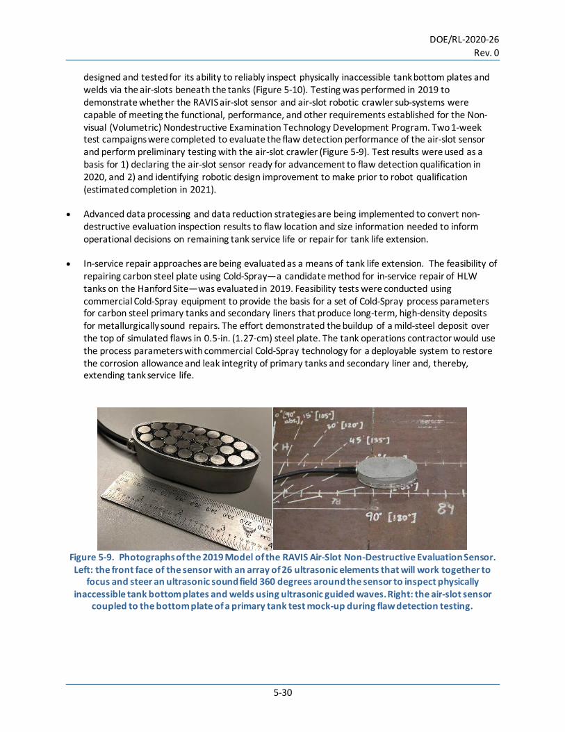
• The robotic air-slot volumetric inspection system (RAVIS) that is being engineered for Hanford tank bottom inspections (Figure 5-9) underwent design reviews and site acceptance testing (requirement verification testing). The RAVIS is a robotic ultrasonic guided wave inspection system that is being
DOE/RL-2020-26 Rev. 0
5-30
designed and tested for its ability to reliably inspect physically inaccessible tank bottom plates and welds via the air-slots beneath the tanks (Figure 5-10). Testing was performed in 2019 to demonstrate whether the RAVIS air-slot sensor and air-slot robotic crawler sub-systems were capable of meeting the functional, performance, and other requirements established for the Non-visual (Volumetric) Nondestructive Examination Technology Development Program. Two 1-week test campaigns were completed to evaluate the flaw detection performance of the air-slot sensor and perform preliminary testing with the air-slot crawler (Figure 5-9). Test results were used as a basis for 1) declaring the air-slot sensor ready for advancement to flaw detection qualification in 2020, and 2) and identifying robotic design improvement to make prior to robot qualification (estimated completion in 2021).
• Advanced data processing and data reduction strategies are being implemented to convert non-destructive evaluation inspection results to flaw location and size information needed to inform operational decisions on remaining tank service life or repair for tank life extension.
• In-service repair approaches are being evaluated as a means of tank life extension. The feasibility of
repairing carbon steel plate using Cold-Spray—a candidate method for in-service repair of HLW tanks on the Hanford Site—was evaluated in 2019. Feasibility tests were conducted using commercial Cold-Spray equipment to provide the basis for a set of Cold-Spray process parameters for carbon steel primary tanks and secondary liners that produce long-term, high-density deposits for metallurgically sound repairs. The effort demonstrated the buildup of a mild-steel deposit over the top of simulated flaws in 0.5-in. (1.27-cm) steel plate. The tank operations contractor would use the process parameters with commercial Cold-Spray technology for a deployable system to restore the corrosion allowance and leak integrity of primary tanks and secondary liner and, thereby, extending tank service life.
Figure 5-9. Photographs of the 2019 Model of the RAVIS Air-Slot Non-Destructive Evaluation Sensor. Left: the front face of the sensor with an array of 26 ultrasonic elements that will work together to
focus and steer an ultrasonic sound field 360 degrees around the sensor to inspect physically inaccessible tank bottom plates and welds using ultrasonic guided waves. Right: the air-slot sensor
coupled to the bottom plate of a primary tank test mock-up during flaw detection testing.
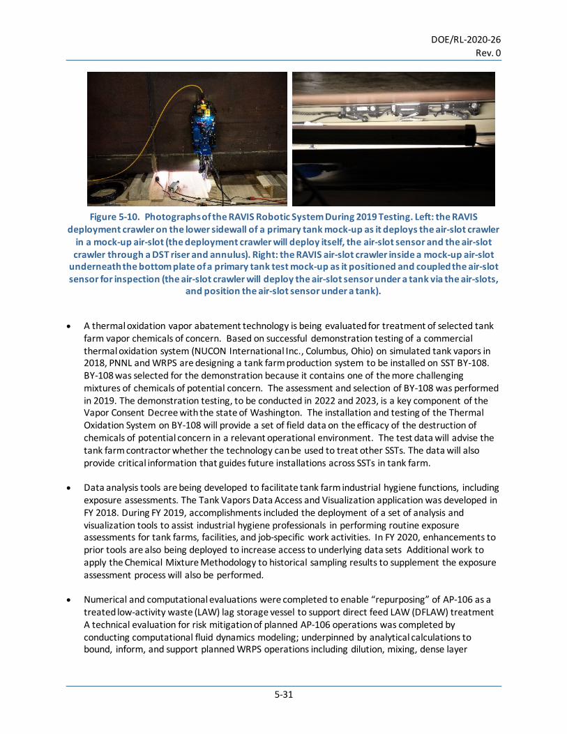
DOE/RL-2020-26 Rev. 0
5-31
Figure 5-10. Photographs of the RAVIS Robotic System During 2019 Testing. Left: the RAVIS
deployment crawler on the lower sidewall of a primary tank mock-up as it deploys the air-slot crawler in a mock-up air-slot (the deployment crawler will deploy itself, the air-slot sensor and the air-slot crawler through a DST riser and annulus). Right: the RAVIS air-slot crawler inside a mock-up air-slot
underneath the bottom plate of a primary tank test mock-up as it positioned and coupled the air-slot sensor for inspection (the air-slot crawler will deploy the air-slot sensor under a tank via the air-slots,
and position the air-slot sensor under a tank).
• A thermal oxidation vapor abatement technology is being evaluated for treatment of selected tank
farm vapor chemicals of concern. Based on successful demonstration testing of a commercial thermal oxidation system (NUCON International Inc., Columbus, Ohio) on simulated tank vapors in 2018, PNNL and WRPS are designing a tank farm production system to be installed on SST BY-108. BY-108 was selected for the demonstration because it contains one of the more challenging mixtures of chemicals of potential concern. The assessment and selection of BY-108 was performed in 2019. The demonstration testing, to be conducted in 2022 and 2023, is a key component of the Vapor Consent Decree with the state of Washington. The installation and testing of the Thermal Oxidation System on BY-108 will provide a set of field data on the efficacy of the destruction of chemicals of potential concern in a relevant operational environment. The test data will advise the tank farm contractor whether the technology can be used to treat other SSTs. The data will also provide critical information that guides future installations across SSTs in tank farm.
• Data analysis tools are being developed to facilitate tank farm industrial hygiene functions, including exposure assessments. The Tank Vapors Data Access and Visualization application was developed in FY 2018. During FY 2019, accomplishments included the deployment of a set of analysis and visualization tools to assist industrial hygiene professionals in performing routine exposure assessments for tank farms, facilities, and job-specific work activities. In FY 2020, enhancements to prior tools are also being deployed to increase access to underlying data sets Additional work to apply the Chemical Mixture Methodology to historical sampling results to supplement the exposure assessment process will also be performed.
• Numerical and computational evaluations were completed to enable “repurposing” of AP-106 as a treated low-activity waste (LAW) lag storage vessel to support direct feed LAW (DFLAW) treatment A technical evaluation for risk mitigation of planned AP-106 operations was completed by conducting computational fluid dynamics modeling; underpinned by analytical calculations to bound, inform, and support planned WRPS operations including dilution, mixing, dense layer

DOE/RL-2020-26 Rev. 0
5-32
additions, and decanting of the cesium-rich supernatant layer. Results informed baseline operations changes and additional analytical and computational evaluations were conducted to evaluate these changes and establish tolerable risk levels for AP- 106 “repurposing” operations. The AP-106 retrieval and mixing operations were successfully completed as predicted by the technical evaluation.
• Structural integrity analysis of record was completed to qualify the AN and AW DSTs for increased storage volume. Since 2003, PNNL has performed the structural integrity analyses of record for the DSTs and SSTs at the Hanford Site. These analyses dictate the maximum waste level allowed in the DSTs. In 2008, PNNL completed a structural analysis that demonstrated that the AP tanks could safely store an additional 38 in. (96.5 cm) of waste, representing 720,000 gal (2.7 million L) of additional storage volume in the eight AP tanks. In 2017, a similar analysis was performed to qualify the AN and AW tanks for increased waste height. In 2019, the seismic spectra are being updated to the 2014 probabilistic seismic hazard analysis and the analysis is on schedule for completion in 2020. Conclusions similar to those of the AP analysis are expected, which could increase the storage capacity of the 13 AN and AW tanks by 1,170,000 gal (4.3 million liters). Verified tank structural models were used to assess the addition of new tank dome risers for increased access during waste retrieval. These models were also used in 2019 to evaluate the current as-built condition of the AX SSTs.
• Online configured sensors are being developed for in situ, real-time chemical analysis of Hanford Site waste in tanks and pipes. Laboratory testing was performed with an online configured Raman spectroscopy system to detect and quantify Raman-active analytes in a Hanford tank waste sample. Measurements on waste simulants were performed to populate the training data set of a chemometric model that will be used to automate the interpretation of Raman spectra in tank waste for chemical analyte identification and quantification, both of which are ultimately necessary to support tank farm and WTP waste management and processing operations. An online Raman spectroscopy system and other complementary online instruments could be qualified and configured for field deployment (tank farms) in the future to provide real-time chemical analysis results, offset the demand for traditional sampling and offline analysis, and drive worker exposure hazards as low as reasonably achievable.
• An online configured Raman spectroscopy system is also being tested to support the measurements of very low concentration Raman-active analytes in the Low Activity Waste Facility off gas streams and Effluent Management Facility (EMF) waste streams. By using alternate wavelength laser systems combined with enhance chemometrics, Raman sensitivities are greatly improved and can monitor low concentration chemical flow streams in real-time. This can improve process monitoring and significantly lower laboratory sampling costs and operational costs. This effort is evaluating long term process improvements for DFLAW operations.
• WRPS worked with the Tank Integrity Expert Panel Corrosion Subgroup to develop new DST waste chemistry limits to prohibit stress corrosion cracking and minimize pitting corrosion. The technical basis for the new waste chemistry limits utilized a statistically designed test matrix and subsequent corrosion testing to develop a pitting factor relating inhibitive and aggressive waste constituents. The proposed controls were validated against historical testing results to ensure that they were appropriately conservative. The new DST waste chemistry limits better protect the tanks from

DOE/RL-2020-26 Rev. 0
5-33
halide-induced pitting corrosion while remaining protective against stress corrosion cracking. The controls were implemented into WRPS requirements documents in October 2019.
• WRPS obtained core samples of tank 241-AY-101 and 241-AN-107 during FY 2019 Core samples collect solids material and oftentimes provide a full vertical compositional profile. They are an integral part of understanding the current condition of the DSTs and evaluating any potential corrosion risks associated with the waste.
5.2.2 Single-Shell Tank Closure and Interim Measures Program P Rutland The SST Closure and Interim Measures Program is responsible for the closure of SST WMAs, conducting PAs, and performing agreed upon interim measures in and around SST WMAs. Current efforts are focused on: • Reaching agreement with regulatory agencies on the content of closure plans to allow closure of the
241-C-200 Series Tanks to proceed.
• Developing closure documents for other WMA C components.
• Completing field work required to retrieve 241-C-301 Catch Tank.
• Evaluating the conditions of 244-CR Vault and seven WMA C diversion boxes.
• Completing the U.S. Nuclear Regulatory Commission (NRC) and public review of the Waste Incidental to Reprocessing (WIR) Evaluation and the DOE O 435.1 PA for WMA C and finalizing both documents for public release.
• Completing resolution of comments received from Ecology on three of the four HFFACO initial drafts of PA-related documents (see Appendix I in Attachment 2 – Action Plan of TPA) for WMA C (RPP-ENV-58806, Rev 0; RPP-RPT-58329, Rev 2; RPP-RPT-59197, Rev 1)
• Performing maintenance on the completed DOE O 435.1 PA for WMA C.
• Completing initial drafts of two of the four HFFACO PA-related documents (See Appendix I in Attachment 2 – Action Plan of TPA) for WMA A-AX.
• Developing a WMA A-AX Closure Conceptual Design.
• Performing field work at WMA A-AX to support characterization and closure efforts.
• Designing interim surface barriers and planning for future interim measures.
• Monitoring the performance of implemented interim measures.
• Conducting soil characterization to support interim measures.

DOE/RL-2020-26 Rev. 0
5-34
Closure activities in CY 2019 included performing field and engineering activities to support WMA C closure, conducting and planning characterization activities at WMA A-AX, planning for WMA A-AX Closure, and continuing to develop and get approval of WMA C closure documents. All closure documents requiring regulatory approvals for the first phase of closure of WMA C were with the approving organizations in CY 2019. By the end of CY2019: • The draft WMA C WIR Evaluation had undergone a public review and review by the U.S. Nuclear
Regulatory Commission was underway.
• Resolution of comments received from Ecology on the RCRA Tiers 1 (SST System), 2 (WMA C), and 3 (241-C-200 Series Tanks) Closure Plans was underway.
• Resolution of comments received from Ecology on three of the four HFFACO PA documents (See Appendix I of Attachment 2 – Action Plan) for WMA C was underway.
• The DOE Order 435.1 Tier 1 (WMA C) and Tier 2 (241-C-200 Series Tanks) Closure Plans were under review by DOE.
• Grout formulas for closure of the 241-C- Series tanks and associated pipe encasements were
developed and initial testing completed. • Drilling, logging, and sampling of five direct push locations for WMA A-AX Focus Area 1, the area
around tanks 241-A-104 and 241-A-105 (per RPP-PLAN-62041) was completed. Logging of 18 drywells in this focus area were also completed.
• RPP-PLAN-63020, Sampling and Analysis Plan for WMA A-AX Focus Area 2 (Southwestern Area of A Farm) was developed and field work was initiated.
• RPP-PLAN-63022, Field Sampling and Analysis Plan for Soil Sampling Between Tanks T-102 and T-105, was developed. Field work to support characterization for interim measures is anticipated to be initiated in CY 2020.
5.2.2.1 Performance Assessments. Work was conducted during CY 2019 to support ongoing PA development and documentation updates associated with WMA C, the IDF, and WMA A-AX. The WMA C and WMA A-AX PAs support closure of WMA C and WMA A-AX, respectively, while the IDF PA supports operations of the IDF. Resolution of comments received from Ecology on three of the four HFFACO initial drafts of PA analysis documents (Appendix I in Attachment 2 – TPA Action Plan) for WMA C (RPP-ENV-58806; RPP-RPT-58329; RPP-RPT-59197) have continued. The fourth HFFACO analysis document, the DOE Order 435.1 PA, is outside of Ecology’s regulatory oversight. In addition, Maintenance and Monitoring Plans and an Unresolved Waste Management Question procedure were maintained in support of the WMA C PA maintenance effort. This work is being
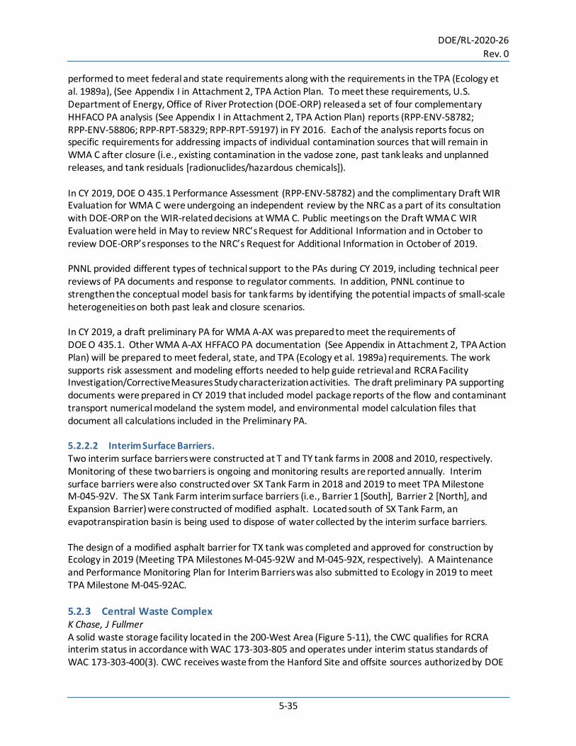
DOE/RL-2020-26 Rev. 0
5-35
performed to meet federal and state requirements along with the requirements in the TPA (Ecology et al. 1989a), (See Appendix I in Attachment 2, TPA Action Plan. To meet these requirements, U.S. Department of Energy, Office of River Protection (DOE-ORP) released a set of four complementary HHFACO PA analysis (See Appendix I in Attachment 2, TPA Action Plan) reports (RPP-ENV-58782; RPP-ENV-58806; RPP-RPT-58329; RPP-RPT-59197) in FY 2016. Each of the analysis reports focus on specific requirements for addressing impacts of individual contamination sources that will remain in WMA C after closure (i.e., existing contamination in the vadose zone, past tank leaks and unplanned releases, and tank residuals [radionuclides/hazardous chemicals]). In CY 2019, DOE O 435.1 Performance Assessment (RPP-ENV-58782) and the complimentary Draft WIR Evaluation for WMA C were undergoing an independent review by the NRC as a part of its consultation with DOE-ORP on the WIR-related decisions at WMA C. Public meetings on the Draft WMA C WIR Evaluation were held in May to review NRC’s Request for Additional Information and in October to review DOE-ORP’s responses to the NRC’s Request for Additional Information in October of 2019. PNNL provided different types of technical support to the PAs during CY 2019, including technical peer reviews of PA documents and response to regulator comments. In addition, PNNL continue to strengthen the conceptual model basis for tank farms by identifying the potential impacts of small-scale heterogeneities on both past leak and closure scenarios. In CY 2019, a draft preliminary PA for WMA A-AX was prepared to meet the requirements of DOE O 435.1. Other WMA A-AX HFFACO PA documentation (See Appendix in Attachment 2, TPA Action Plan) will be prepared to meet federal, state, and TPA (Ecology et al. 1989a) requirements. The work supports risk assessment and modeling efforts needed to help guide retrieval and RCRA Facility Investigation/Corrective Measures Study characterization activities. The draft preliminary PA supporting documents were prepared in CY 2019 that included model package reports of the flow and contaminant transport numerical modeland the system model, and environmental model calculation files that document all calculations included in the Preliminary PA. 5.2.2.2 Interim Surface Barriers. Two interim surface barriers were constructed at T and TY tank farms in 2008 and 2010, respectively. Monitoring of these two barriers is ongoing and monitoring results are reported annually. Interim surface barriers were also constructed over SX Tank Farm in 2018 and 2019 to meet TPA Milestone M-045-92V. The SX Tank Farm interim surface barriers (i.e., Barrier 1 [South], Barrier 2 [North], and Expansion Barrier) were constructed of modified asphalt. Located south of SX Tank Farm, an evapotranspiration basin is being used to dispose of water collected by the interim surface barriers. The design of a modified asphalt barrier for TX tank was completed and approved for construction by Ecology in 2019 (Meeting TPA Milestones M-045-92W and M-045-92X, respectively). A Maintenance and Performance Monitoring Plan for Interim Barriers was also submitted to Ecology in 2019 to meet TPA Milestone M-045-92AC. 5.2.3 Central Waste Complex K Chase, J Fullmer A solid waste storage facility located in the 200-West Area (Figure 5-11), the CWC qualifies for RCRA interim status in accordance with WAC 173-303-805 and operates under interim status standards of WAC 173-303-400(3). CWC receives waste from the Hanford Site and offsite sources authorized by DOE
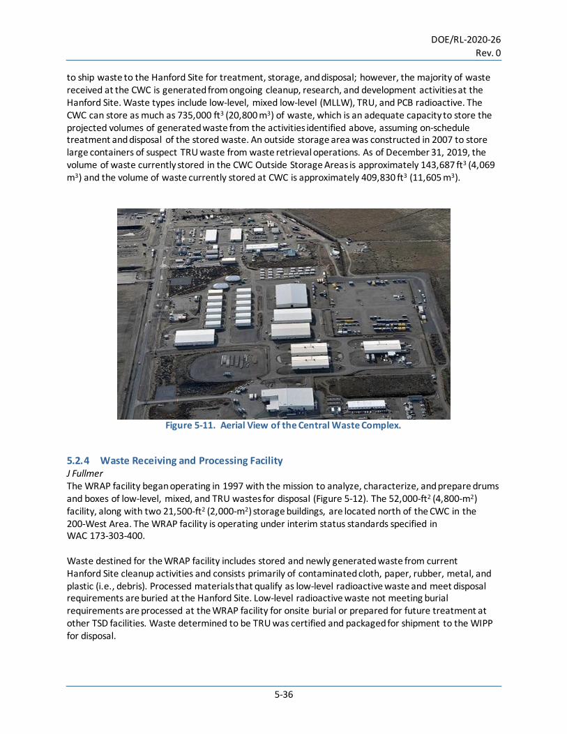
DOE/RL-2020-26 Rev. 0
5-36
to ship waste to the Hanford Site for treatment, storage, and disposal; however, the majority of waste received at the CWC is generated from ongoing cleanup, research, and development activities at the Hanford Site. Waste types include low-level, mixed low-level (MLLW), TRU, and PCB radioactive. The CWC can store as much as 735,000 ft3 (20,800 m3) of waste, which is an adequate capacity to store the projected volumes of generated waste from the activities identified above, assuming on-schedule treatment and disposal of the stored waste. An outside storage area was constructed in 2007 to store large containers of suspect TRU waste from waste retrieval operations. As of December 31, 2019, the volume of waste currently stored in the CWC Outside Storage Areas is approximately 143,687 ft3 (4,069 m3) and the volume of waste currently stored at CWC is approximately 409,830 ft3 (11,605 m3).
Figure 5-11. Aerial View of the Central Waste Complex.
5.2.4 Waste Receiving and Processing Facility J Fullmer The WRAP facility began operating in 1997 with the mission to analyze, characterize, and prepare drums and boxes of low-level, mixed, and TRU wastes for disposal (Figure 5-12). The 52,000-ft2 (4,800-m2) facility, along with two 21,500-ft2 (2,000-m2) storage buildings, are located north of the CWC in the 200-West Area. The WRAP facility is operating under interim status standards specified in WAC 173-303-400. Waste destined for the WRAP facility includes stored and newly generated waste from current Hanford Site cleanup activities and consists primarily of contaminated cloth, paper, rubber, metal, and plastic (i.e., debris). Processed materials that qualify as low-level radioactive waste and meet disposal requirements are buried at the Hanford Site. Low-level radioactive waste not meeting burial requirements are processed at the WRAP facility for onsite burial or prepared for future treatment at other TSD facilities. Waste determined to be TRU was certified and packaged for shipment to the WIPP for disposal.
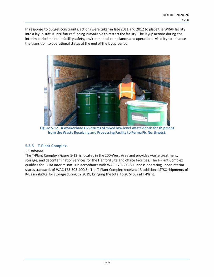
DOE/RL-2020-26 Rev. 0
5-37
In response to budget constraints, actions were taken in late 2011 and 2012 to place the WRAP facility into a layup status until future funding is available to restart the facility. The layup actions during the interim period maintain facility safety, environmental compliance, and operational viability to enhance the transition to operational status at the end of the layup period.
Figure 5-12. A worker loads 65 drums of mixed low-level waste debris for shipment
from the Waste Receiving and Processing Facility to Perma Fix Northwest.
5.2.5 T-Plant Complex. JR Hultman The T-Plant Complex (Figure 5-13) is located in the 200-West Area and provides waste treatment, storage, and decontamination services for the Hanford Site and offsite facilities. The T-Plant Complex qualifies for RCRA interim status in accordance with WAC 173-303-805 and is operating under interim status standards of WAC 173-303-400(3). The T-Plant Complex received 13 additional STSC shipments of K-Basin sludge for storage during CY 2019, bringing the total to 20 STSCs at T-Plant.

DOE/RL-2020-26 Rev. 0
5-38
Figure 5-13. Aerial View of the T-Plant Complex.
5.2.6 Canister Storage Building DJ Watson The CSB is a large 42,000-ft2 (3,902-m2) facility located in the 200-East Area. The facility stores approximately 2,300 tons (2,086 metric tons) of spent nuclear fuel packaged in 412 multi-canister overpacks from the 100-K Basins, 100-N Reactor, and T-Plant. The multi-canister overpacks are stored in 220 carbon-steel tubes in a below-grade concrete vault. The irradiated fuel was cleaned, packaged, dried, and relocated to the CSB beginning in 2004 to provide safe interim storage in a consolidated location, allowing for cleanup of older facilities, which reduces the cleanup footprint of the Hanford Site and risk. The CSB has a design life of 40 years and will safely store the multi-canister overpacks until they can be placed in the National Repository. The CSB was originally planned to be used for the storage of glass logs of vitrified tank wastes. Per the National Environmental Policy Act ROD to the DOE/EIS-0245F, Final Environmental Impact Statement Management of Spent Nuclear Fuel from the K Basins at the Hanford Site, Richland, Washington, it was decided to store spent nuclear fuel in the CSB. Construction of CSB was completed in May 2000 and commenced receiving K Basin spent nuclear fuel in December 2000. Adjacent to the CSB is the Interim Storage Area, which also contains spent nuclear fuel from other sources packaged in various containers. This spent nuclear fuel will be subsequently repackaged and sent to the National Repository. 5.2.7 Low-level Burial Grounds JR Hultman, KL Chase, SR Myrick The low-level burial grounds (LLBG) consist of eight separate burial areas regulated under the AEA: two are located in the 200-East Area and six are located in the 200-West Area. Two of the burial grounds are used for disposal of LLW and mixed waste (i.e., low-level radioactive waste with a dangerous waste component regulated by WAC 173-303). Located in the 200-West Area, the 218-W-5 Burial Ground contains Trenches 31 and 34; in the 200-East Area, the 218-E-12B Burial Ground contains Trench 94,
DOE/RL-2020-26 Rev. 0
5-39
which is dedicated for disposal of defueled U.S. Navy reactor compartments. Trenches that contain mixed LLW are regulated under RCRA. Five burial grounds in the 200-West Area were used to dispose of LLW and/or retrievable storage of TRU waste, as were portions of the 218-E-12B Burial Ground. The 218-W-6 Burial Ground has never received waste. The LLBGs are operating under interim status standards specified in applicable sections of WAC 173-303, “Dangerous Waste Regulations.” In addition, the remedial investigation/feasibility study work plan (DOE/RL-2004-60) supports remediation of the CERCLA areas within the LLBG and coordinates with the RCRA TSDs closure. 5.2.7.1 Low-level Waste Burial Ground 218-W-5, Trenches 31 and 34. Trenches 31 and 34 (Figure 5-14) are rectangular landfills with approximate base dimensions of 250 by 100 ft (76 by 30 m), with a variable depth of 30 to 40 ft (9 to 12 m). The trenches comply with WAC 173-303 requirements for double liners and leachate removal/collection systems. These lined disposal units were originally designated for mixed LLW; however, disposal of LLW in the unlined trenches ceased on June 23, 2004. Since that date, Trenches 31 and 34 have accepted LLW and mixed LLW for disposal. Disposal in Trench 31 began in May 2005, and disposal in Trench 34 began in September 1999. The first operational layer of waste containers in both trenches have been covered with compacted gravel and soil, and waste is currently being placed on the second waste layer in both trenches. As of December 31, 2019, Trench 31 contains approximately 250,960 ft3 (7,106 m3) of waste in approximately 4,082 waste containers. Trench 34 contains approximately 191,019 ft3 (5,409 m3) of waste in 5,341 waste containers. In 2019, 149 containers totaling 14,593 ft3 (413 m3) of waste were disposed of in Trenches 31 and 34. 5.2.7.2 Low-Level Waste Burial Ground, Trench 94. The LLBG Trench 94 received two defueled U.S. Navy reactor compartments in 2019. The total number of reactor compartments received into Trench 94 (218-E-12B Burial Ground) is 135 as of December 31, 2019. All U.S. Navy reactor compartments shipped to the Hanford Site for disposal in trench 94 originated from decommissioned, defueled nuclear-powered submarines or cruisers. Decommissioned submarine reactor compartments are approximately 33 ft (10 m) in diameter, 47 ft (14.3 m) long, and weigh between 1,000 and 1,500 tons (900 and 1,362 metric tons). Decommissioned cruiser reactor compartments are approximately 33 ft (10 m) in diameter, 42 ft (12.8 m) high, and weigh approximately 1,500 tons (1,362 metric tons).

DOE/RL-2020-26 Rev. 0
5-40
Figure 5-14. Trenches 31 (Bottom Trench) and 34 (Top Trench) are Used to Store and Dispose
of Low-Level Waste and Mixed Low-Level Waste from Hanford Site Work.
5.2.8 Waste Encapsulation and Storage Facility DJ Watson Located in the 200-East Area, the WESF was constructed in 1970 and 1971 on the west end of B-Plant and became active in 1974. The WESF qualifies for RCRA interim status in accordance with WAC 173-303-805 and is operating under interim status standards of WAC 173-303-400(3). The WESF is a storage only unit for strontium- and cesium- salts encapsulated in double-containment stainless-steel capsules in underwater pool cells. The water provides cooling and shielding for the capsules, which are considered sealed sources. The mission of the WESF was encapsulation and storage of cesium chloride and strontium fluoride salts that had been separated from the Hanford Site’s high-level radioactive tank waste. The current mission of WESF is safe storage of the cesium and strontium capsules. The facility is a two-story, 20,000-ft2 (1,860-m2) building that is 157-ft (48-m) long and 40-ft (12-m) high. The facility is constructed of steel-reinforced concrete and partitioned into seven hot cells, a hot cell service area, operating areas, building service areas, and a pool cell area. The hot cells are labeled A through G. Initial RCRA closure of Hot Cells A through F was achieved on April 10, 2017, through grouting the hot cells to fix any radioactive materials present. Only Cell G remains active for supporting cesium and strontium capsule storage and eventual removal. Other building areas for instrumentation, monitoring, utility support, and manipulator repair associated with Cell G and the pool cells remain in service. In May 2018 DOE issued an amended Record of Decision (ROD) to the Final Tank Closure and Waste Management Environmental Impact Statement for the Hanford Site, Richland, Washington

DOE/RL-2020-26 Rev. 0
5-41
(DOE/EIS-0391) for the management of cesium and strontium capsules at the Hanford Site. This amended ROD is found in the 83 FR 23270. The decision was to transfer the capsules in storage at WESF to a new interim dry storage facility. In CY 2019 Ecology prepared and issued for public comment a draft RCRA Part B permit for WESF including provisions for removal and packaging the capsules for dry storage. In CY 2019, Ecology also prepared and issued for public comment a draft RCRA Part B permit for the Capsule Storage Area for the interim storage of the capsules. Permits are planned to be issued in CY 2020 for both facilities as a precursor to commencement of construction associated with capsule removal from WESF and interim storage at the Capsule Storage Area. 5.2.9 Integrated Disposal Facility WA Borlaug, BL Lawrence, L Dittmer The IDF (Figure 5-15) is an unused landfill located in the south-central part of the 200-East Area. The IDF is an expandable lined landfill (i.e., a double high-density polyethylene (HDPE)-lined trench with leachate collection and a leak detection system). The landfill is divided lengthwise (north to south) into two distinct cells: the east cell (cell 2) was originally intended for disposal of low-level radioactive waste (non-RCRA permitted) and the west cell (cell 1) was for disposal of MLLW (radioactive and RCRA-regulated hazardous waste). The west cell is currently a permitted TSD facility under the Hanford Site RCRA Permit (WA7890008967). A Permit Modification Request was submitted in 2019 to Ecology to allow disposal of MLLW in both cells (e.g., vitrified LAW from the WTP). The permit modification adds non-CERCLA waste from Hanford projects, secondary waste from WTP, and mixed waste generated by IDF operations to be disposed of in IDF. The IDF has a process design capacity of 2.89 million ft3 (82,000 m3). The IDF is referenced in DOE/EIS-0391 as a future disposal option for Hanford Site wastes.
Figure 5-15. Aerial View of the Integrated Disposal Facility.
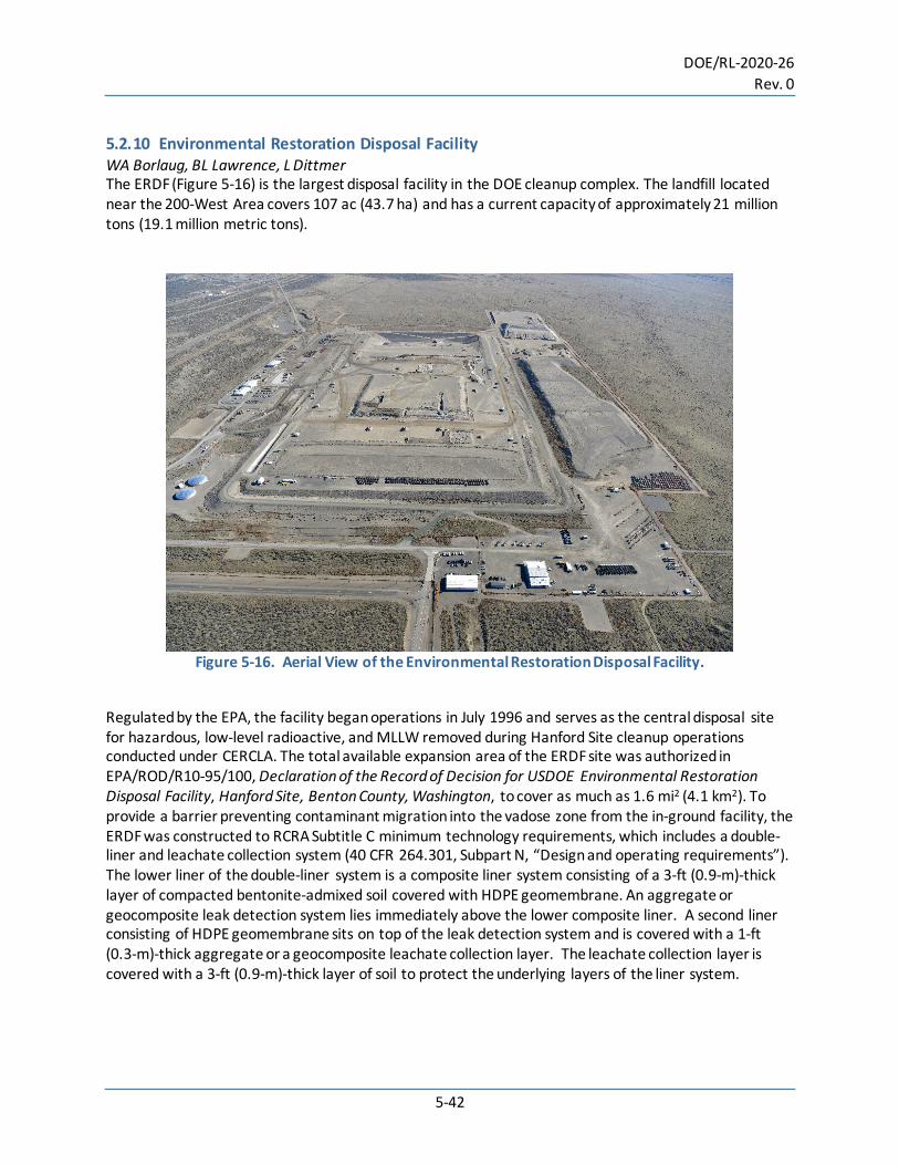
DOE/RL-2020-26 Rev. 0
5-42
5.2.10 Environmental Restoration Disposal Facility WA Borlaug, BL Lawrence, L Dittmer The ERDF (Figure 5-16) is the largest disposal facility in the DOE cleanup complex. The landfill located near the 200-West Area covers 107 ac (43.7 ha) and has a current capacity of approximately 21 million tons (19.1 million metric tons).
Figure 5-16. Aerial View of the Environmental Restoration Disposal Facility.
Regulated by the EPA, the facility began operations in July 1996 and serves as the central disposal site for hazardous, low-level radioactive, and MLLW removed during Hanford Site cleanup operations conducted under CERCLA. The total available expansion area of the ERDF site was authorized in EPA/ROD/R10-95/100, Declaration of the Record of Decision for USDOE Environmental Restoration Disposal Facility, Hanford Site, Benton County, Washington, to cover as much as 1.6 mi2 (4.1 km2). To provide a barrier preventing contaminant migration into the vadose zone from the in-ground facility, the ERDF was constructed to RCRA Subtitle C minimum technology requirements, which includes a double-liner and leachate collection system (40 CFR 264.301, Subpart N, “Design and operating requirements”). The lower liner of the double-liner system is a composite liner system consisting of a 3-ft (0.9-m)-thick layer of compacted bentonite-admixed soil covered with HDPE geomembrane. An aggregate or geocomposite leak detection system lies immediately above the lower composite liner. A second liner consisting of HDPE geomembrane sits on top of the leak detection system and is covered with a 1-ft (0.3-m)-thick aggregate or a geocomposite leachate collection layer. The leachate collection layer is covered with a 3-ft (0.9-m)-thick layer of soil to protect the underlying layers of the liner system.

DOE/RL-2020-26 Rev. 0
5-43
Designed to be expanded as needed, ERDF consists of disposal areas called cells. There are currently 10 cells at ERDF. After completion of waste disposal operations, a 15-ft (4.6-m)-thick enhanced RCRA Subtitle-C final cover will be placed over the cells. As of December 31, 2019, DOE and its contractors have disposed of 18.5 million tons (16.8 million metric tons) of contaminated material at the ERDF since the facility began operations in 1996. The majority of cleanup waste disposed at ERDF is from the 220 mi2 (570 km2) River Corridor located along the banks of the Columbia River. The waste consists mainly of soil contaminated during operation of the Hanford Site’s nine plutonium production reactors and support facilities from 1943 to 1987, as well as contaminated rubble from building demolition. In addition, ERDF receives cleanup waste from other Hanford Site locations. 5.2.11 200 Area Effluent Treatment Facility. S Scott The 200 Area ETF (Figure 5-17) is located in the 200-East Area. The 200 Area ETF stores and treats liquid effluent to remove toxic metals, radionuclides, and ammonia, in addition to destroying organic compounds. The treatment process constitutes best available technology and includes pH adjustment, filtration, ultraviolet light and peroxide oxidation to destroy organic compounds, reverse osmosis to remove dissolved solids, and ion exchange to remove the last traces of contaminants. The facility began operating in December 1995 and has a maximum treatment capacity of 150 gal (570 L) per minute. The 200 Area ETF operates in accordance with the RCRA Permit. The effluent discharges from the 200 Area ETF are managed in accordance with limitations set forth in the State Waste Discharge Permit ST-4500 (ST0004500) and the 200 Area ETF Delisting Petition approval conditions. The treated effluent is stored in tanks, sampled and analyzed, and discharged via a dedicated pipeline to the State-Approved Land Disposal Site (also known as the 616-A Crib), an underground drain field located just north of the 200-West Area. Percolation rates for the field were established by site testing and evaluation of soil characteristics. Tritium in the liquid effluent from the ETF cannot be practically removed. The location of the disposal site maximizes the time for migration of tritium to the Columbia River to allow for radioactive decay (the half-life of tritium is 12.35 years). The 200 Area ETF processed 4.45 million gal (16.8 million L) of wastewater from LERF in CY 2019.

DOE/RL-2020-26 Rev. 0
5-44
Figure 5-17. The Effluent Treatment Facility Receives Liquids from
the Liquid Effluent Retention Facility.
5.2.12 Liquid Effluent Retention Facility. South of the ETF, the LERF (Figure 5-18) consists of three RCRA-compliant surface impoundments to store process condensate from the 242-A Evaporator, groundwater from various operable unit P&T systems, leachate from ERDF and LLBG Trenches 31 and 34, and other aqueous waste. The LERF provides a steady flow and consistent pH for the 200 Area ETF feed. Each basin has a maximum permitted capacity of 7.8 million gal (29.5 million L) and is constructed of two flexible HDPE membrane liners. A system is provided to detect, collect, and remove leachate from between the primary and secondary liners. Beneath the secondary liner is a soil and bentonite clay barrier, should the other liners fail. Each basin has a floating membrane cover constructed of very low-density polyethylene or chlorosulfonated polyethylene to keep out windblown soil and weeds and minimize evaporation of organic compounds and tritiated water that may be present in the basin contents. The facility began operating in April 1994 and receives liquid waste resulting from RCRA- and CERCLA-regulated cleanup activities. The volume of wastewater received for the LERF basin storage in CY 2019 was approximately 2.34 million gal (8.87 million L). The largest single contributor to wastewater received into LERF was approximately 0.41 million gal (1.56 million L) of mixed waste burial trench leachate. Approximately 4.45 million gal (16.8 million L) of wastewater in LERF was treated at ETF in CY 2019. Treated effluent wastewater is discharged to the State-Approved Land Disposal Site. The volume of wastewater being stored in the LERF at the end of CY 2019 was approximately 9.82 million gal (37.2 million L).
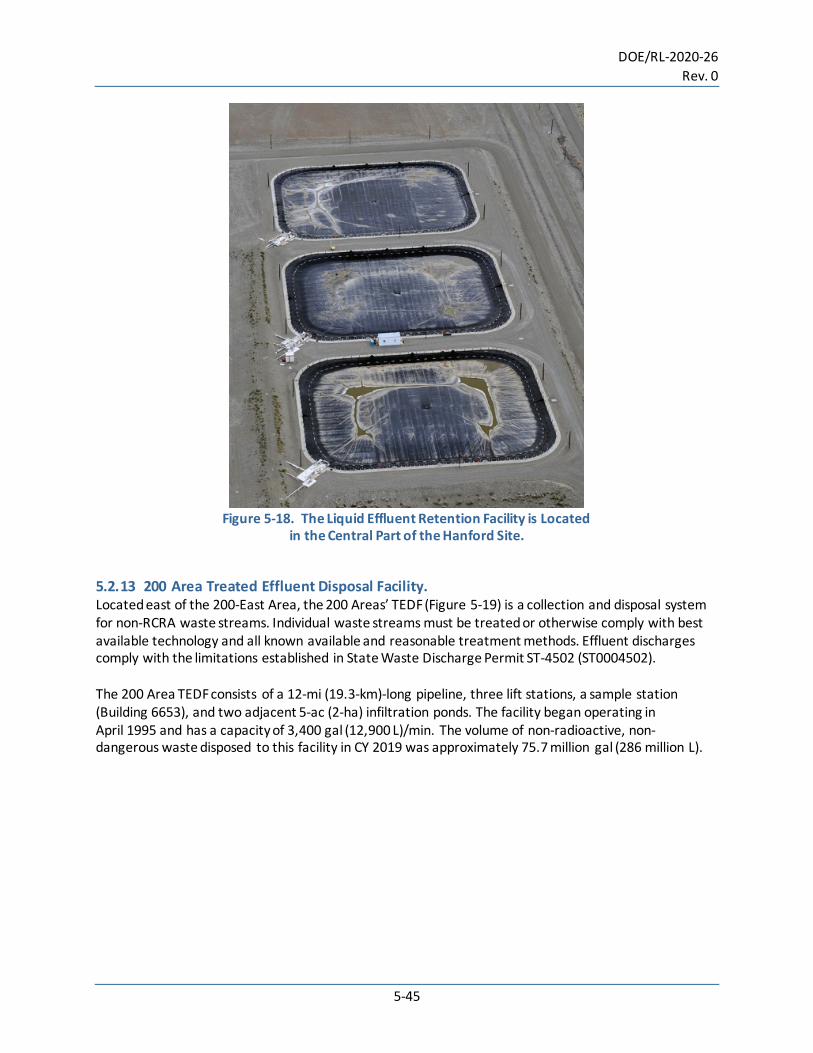
DOE/RL-2020-26 Rev. 0
5-45
Figure 5-18. The Liquid Effluent Retention Facility is Located
in the Central Part of the Hanford Site.
5.2.13 200 Area Treated Effluent Disposal Facility. Located east of the 200-East Area, the 200 Areas’ TEDF (Figure 5-19) is a collection and disposal system for non-RCRA waste streams. Individual waste streams must be treated or otherwise comply with best available technology and all known available and reasonable treatment methods. Effluent discharges comply with the limitations established in State Waste Discharge Permit ST-4502 (ST0004502). The 200 Area TEDF consists of a 12-mi (19.3-km)-long pipeline, three lift stations, a sample station (Building 6653), and two adjacent 5-ac (2-ha) infiltration ponds. The facility began operating in April 1995 and has a capacity of 3,400 gal (12,900 L)/min. The volume of non-radioactive, non-dangerous waste disposed to this facility in CY 2019 was approximately 75.7 million gal (286 million L).
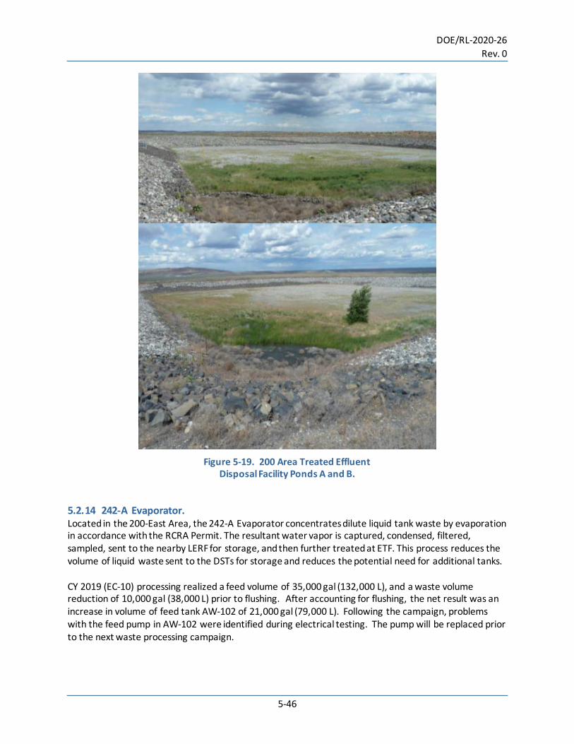
DOE/RL-2020-26 Rev. 0
5-46
Figure 5-19. 200 Area Treated Effluent
Disposal Facility Ponds A and B.
5.2.14 242-A Evaporator. Located in the 200-East Area, the 242-A Evaporator concentrates dilute liquid tank waste by evaporation in accordance with the RCRA Permit. The resultant water vapor is captured, condensed, filtered, sampled, sent to the nearby LERF for storage, and then further treated at ETF. This process reduces the volume of liquid waste sent to the DSTs for storage and reduces the potential need for additional tanks. CY 2019 (EC-10) processing realized a feed volume of 35,000 gal (132,000 L), and a waste volume reduction of 10,000 gal (38,000 L) prior to flushing. After accounting for flushing, the net result was an increase in volume of feed tank AW-102 of 21,000 gal (79,000 L). Following the campaign, problems with the feed pump in AW-102 were identified during electrical testing. The pump will be replaced prior to the next waste processing campaign.
DOE/RL-2020-26 Rev. 0
5-47
5.2.15 Hanford Tank Waste Treatment and Immobilization Plant D Faulk The WTP is being built on 65 ac (26 ha) in the 200-East Area to treat radioactive and hazardous waste stored in 177 underground tanks on the Central Plateau. The WTP comprises four major facilities (Pretreatment Facility, HLW Facility, LAW Facility, and Analytical Laboratory) along with support buildings and associated infrastructure (Balance of Facilities [BOF]). Construction of the WTP is managed in accordance with the RCRA Permit. In 2019, Bechtel National Inc. (BNI) continued executing against its new contract modifications, signed in December 2016 with DOE, that prioritize finishing the LAW Facility, BOF, and Analytical Laboratory to feed waste directly from the Hanford Tank Farms to the LAW facility under an approach called DFLAW. The DFLAW approach calls for the treatment of tank waste in the LAW facility by the end of 2023. As construction is completed, the plant systems and buildings are transferred to a startup and testing phase to perform testing to verify the systems and equipment functions as intended. After the startup phase, a commissioning phase ensures the utilities and process systems are integrated and ready to support future plant operations. A description of the WTP facilities and the progress at each facility in 2019 is provided in the following sections. 5.2.15.1 Pretreatment Facility. The Pretreatment Facility is where waste will be received from the Tank Farms and separated into low-activity and HLW streams for transport to the LAW and HLW facilities for processing. In 2019, DOE and BNI, along with an independent review team, completed an extensive collaborative effort to resolve a series of technical questions related to the Pretreatment and HLW facilities. In June 2019, the last of eight technical decisions for the Pretreatment Facility was resolved. Four years of both small and large-scale testing confirmed that pulse jet mixers can properly mix tank waste to ensure there are no flammable gas buildups inside the facilities’ vessels. This concluded BNI’s work requested by the DOE to successfully resolve the technical decisions for the Pretreatment and HLW facilities identified by an industry expert panel and DOE Secretary of Energy in 2012. 5.2.15.2 High-Level Waste Facility. At this facility, HLW is combined with materials in glass forming high temperature melters and poured into waste container canisters to form a solid, immobilized glass form. In 2018 and 2019, resumption and progress of HLW design engineering activities resumed and has been a primary focus; progress continued to deliver active facility procurements. Limited construction has progressed since 2016. In 2019, equipment such as a thermal catalytic oxidizer, ammonia dilution skid, and radioactive liquid disposal vessel were received for future installation. The catalytic oxidizer and ammonia dilution skid are used to safely destroy organics and nitrogen oxides, the liquid disposal vessel stores recycle generated from off gas processing. Design review was successfully completed for radioactive liquid disposal and melter feed systems and the Facility Preliminary Documented Safety Analysis was also submitted. 5.2.15.3 Low-Activity Waste Facility. In 2019, DOE and BNI opened the doors to a commissioning workforce at a 20,000-ft2 (-m2) two-story annex connected to the LAW Facility. The annex houses the plant’s control room and is key to controlling Direct-Feed Low-Activity Waste operations. The LAW Facility alone contains 93 systems. By
DOE/RL-2020-26 Rev. 0
5-48
the end of 2019 nearly 90% of the Facility systems had finished construction and transitioned into the startup and testing phase while 38% had completed startup and entered the commissioning phase. 5.2.15.4 Analytical Laboratory. Once operational, the Analytical Laboratory will process about 3,000 waste samples annually to support glass formulation and waste-form compliance for the DFLAW approach. In 2019, the Laboratory realized several significant accomplishments. The first team chemists began performing the first scientific work taking place inside the Laboratory. The chemists prepared for their transition to the Hanford Site by first honing their skills and instruments at a smaller-scale offsite lab at Columbia Basin College in Pasco, Washington. During 2018 and 2019, while at the offsite lab, the laboratory team collaborated with WTP engineers to analyze glass made from a slurry of low-activity waste simulant and glass-forming materials. This same analytical method will verify the glass vitrified in the Low-Activity Waste Facility meets DOE standards. During 2019, scientific instruments were installed in the Laboratory and by the end of the year, startup and testing was nearly finished. A majority of systems were handed over to the commissioning phase during the year. 5.2.15.5 Balance of Facilities. The WTP’s BOF is made up of 14 non-nuclear infrastructure support buildings necessary for the plant’s DFLAW operation. The support utilities include electrical power distribution system; backup power systems; compressed air; chilled, process, potable, and fire water systems; steam systems; and communication and control systems. By mid-2019, workers had transitioned all buildings into the startup and testing phase; and by the end of 2019 completed handovers for nearly 83% of a total of 54 BOF systems to the commissioning phase. Final grading, earthwork, and roadway construction also progressed. Of these accomplishments, startup efforts included work for a standby diesel generator building, a steam plant, cooling tower building, and final earthwork and grading surrounding fuel oil and water treatment facilities. 5.2.15.6 Effluent Management Facility. During low-activity waste vitrification, secondary liquid waste is generated from the melter off-gas system and during waste transfer pipe flushing. These liquids will go to the WTP EMF where excess water is evaporated, and the remaining concentrate is sent back into the vitrification process. EMF has four structures: the main processing facility, a utility building, an electrical distribution building, and the low point drain building. In 2019, EMF piping and electrical work progressed, main roofing structural steel was installed, and the building was enclosed with siding and roofing. The team also installed all remaining major vessels inside the facility. A prefabricated 13.8-kilovolt electrical distribution building was also received, assembled and energized. The work involved installing nearly 5,800 ft (1,768 m) of assorted electrical cables and 11,900 ft (3,627 m) of fiber optic cable to the EMF electrical building. 5.3 Long-Term Stewardship J. Shoemake, G Berlin The Hanford Site’s Long-Term Stewardship (LTS) Program is responsible for managing over 220 mi2 (570 km2) of the Hanford Site, an area that includes more than 1,700 WIDS waste sites and six Manhattan Project Era production reactors that have been placed in interim safe storage. The LTS
DOE/RL-2020-26 Rev. 0
5-49
Program works to the direction of the DOE/RL-2010-35, Hanford Long-Term Stewardship Program Plan, to manage the post-cleanup requirements specified in the associated cleanup decision documents. As cleanup is completed (i.e., remedial action objectives are achieved as defined in the applicable decision documents) in a geographic area of the Hanford Site, the area’s mission transitions from cleanup to LTS. Accordingly, contractual responsibilities are transitioned from DOE-RL’s cleanup contractor to the mission support contractor. Since 2010, through collaborative efforts with DOE-RL and its prime contractors, cleaned-up waste sites and other facilities in 14 geographic areas and six cocooned reactor facilities were transitioned from the River Corridor Closure Contractor to Mission Support Alliance’s LTS program via contract modification, which included the preparation of a transition and turnover package. This documentation was prepared for each segment or area transitioned to LTS. The LTS program maintains an internal library of documents referenced in the turnover packages and additional information that may be relevant to the closure history. More than 25,000 cleanup and historic documents have been identified, indexed, and tagged as LTS records that are associated with LTS-managed land areas and WIDS waste sites (Figure 5-20). The LTS Program manages post-cleanup obligations to ensure continued protection of human health and the environment. The LTS Program routinely assesses waste sites with ICs as defined in CERCLA decision documents. ICs are designed to be protective of human health and the environment, and are used to protect the integrity of a response action and minimize the potential for exposure to residual contamination. The Program is also responsible for coordinating with other Hanford Site contractors and leading the preparation and publication of the Hanford Site CERCLA Five-Year Review. The Hanford Site’s fourth CERCLA 5-year review was completed in 2017 (DOE/RL-2016-01) and the next review is due in 2022.
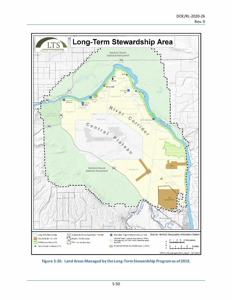
DOE/RL-2020-26 Rev. 0
5-50
Figure 5-20. Land Areas Managed by the Long-Term Stewardship Program as of 2019.

DOE/RL-2020-26 Rev. 0
5-51
The LTS Program also manages post-cleanup obligations, including S&M of interim-stabilized reactor facilities (i.e., safe storage enclosures [SSEs]), WIDS sites, ICs, radiological control posted areas, and revegetated site areas as well as managing other post-cleanup obligations. The LTS Program is also responsible for coordinating Hanford Site CERCLA Five-Year Reviews. In 2019, the following activities included: • S&M activities of the six cocooned reactors (i.e., SSEs), which included conducting an annual exterior
visual inspection; annual radiological monitoring around the outside of the SSEs and inside the vestibules, as required; preventing activities in proximity to the SSEs from affecting the final hazard categorization of the SSEs; conducting exterior visual assessments after off-normal events; upgrading signage on each SSE; sealing gaps in vestibule doorways and siding; and maintaining areas free of vegetation around the SSEs to reduce the potential for fire. Note: The SSEs are designed to protect the reactor for 75 years while radioactive decay continues, ultimately making the structures safe for demolition and removal. The next reactor entries and internal assessments will be conducted in 2025 to ensure that the SSEs are maintained in a safe, environmentally secure, and cost-effective manner until subsequent closure during the final disposition phase of decommissioning.
• S&M of WIDS sites, which included annual inspections of 38 accepted WIDS sites and active WIDS sites, as required; assessing 221 waste sites with ICs as defined in CERCLA decision documents; and managing inactive WIDS sites in accordance with their hazard categorization. These activities support the CERCLA 5-year review assessments for waste sites where hazardous substances, pollutants, or contaminants remain at the site above levels that allow for unlimited use and unrestricted exposure.
• S&M of 26 remaining radiological posted areas, which included inspections of proper postings, conducted annual contamination surveys and implemented biological controls, as needed, to maintain radiation protection.
• S&M of controls for bat habitats, which included ensuring access controls and signage were in place. S&M of revegetated sites including revegetation monitoring of representative sites, reporting on revegetation monitoring results, management of noxious weeds, and conducting rectification and other plantings, as needed. This resulted in a total of 95 ac (38.4 ha) in 2018 and 2019 that either needed complete rework of the site or supplemental work with shrubs and/or forb plugs. New revegetation approaches are being implemented on the Hanford Site to help sites meet their success criteria within their five-year monitoring window.
• Management and decommissioning of underground injection control (UIC) wells. This included
maintaining the Hanford Sitewide list of UIC wells, supporting UIC reports to Ecology, and decommissioning inactive UICs as resources and priorities allow. In 2019, the LTS Program decommissioned 11 underground injection wells within the 100-B/C, 100-N, 100-D, 100-H, and 100-F Areas.

DOE/RL-2020-26 Rev. 0
5-52
• Management and maintenance of the Hanford Site’s LTS Records Library. As of late 2019, over 25,000 records were captured and stored in the LTS electronic records database. These records include historical cleanup information, as well as records created during the execution of LTS activities.
• Updated and issued revision 9 DOE/RL-2001-41, Sitewide Institutional Controls Plan for the Hanford
Site CERCLA Response Actions and RCRA Corrective Actions, to include the additional ICs required by Record of Decision: Hanford Area Superfund Site 100-DR-1, 100-DR-2, 100-HR-1, 100-HR-2, and 100-HR-3 Operable Units (DOE et al. 2018).
Note: The LTS Program continuously maintains current information regarding IC requirements specified in RCRA and CERCLA decision documents, and will update DOE/RL-2001-41, Sitewide Institutional Controls Plan for the Hanford CERCLA Response Actions and RCRA Corrective Actions, as the EPA approves/published new CERCLA records of decision. 5.4 References 40 CFR 264. “Standards for Owners and Operators of Hazardous Waste Treatment, Storage, and
Disposal Facilities,” Subpart N, “Landfills.” Code of Federal Regulations, as amended. Online at http://www.ecfr.gov/cgi-bin/text-idx?SID=3b040000a8b4287717f64e1d13e7b3d8&mc=true&node=pt40.28.264&rgn=div5#se40.28.264_1301.
64 FR 61615. 1999. “Record of Decision: Hanford Comprehensive Land-Use Plan Environmental Impact
Statement “HCP/EIS).” Federal Register, Washington, D.C. Online at https://www.govinfo.gov/content/pkg/FR-1999-11-12/pdf/99-29325.pdf.
78 FR 75913. 2013. “Final Tank Closure and Waste Management Environmental Impact Statement for
the Hanford Site, Richland, Washington.” Federal Register, Washington, D.C. Online at https://www.govinfo.gov/content/pkg/FR-2013-12-13/pdf/2013-29734.pdf.
83 FR 23270. 2018. “Amended Record of Decision for the Management of Cesium and Strontium
Capsules at the Hanford Site, Richland, Washington.” Federal Register, Washington, D.C. Online at https://www.govinfo.gov/app/details/FR-2018-05-18/2018-10643.
Atomic Energy Act of 1954. 42 U.S.C. 2011 et seq. Online at
https://www.nrc.gov/docs/ML1327/ML13274A489.pdf. Comprehensive Environmental Response, Compensation, and Liability Act of 1980, 42 U.S.C. 9601 et
seq., Public Law 107-377. Online at https://www.govinfo.gov/content/pkg/USCODE-2017-title42/pdf/USCODE-2017-title42-chap103.pdf.
DOE, EPA, Ecology. 2005. Record of Decision: 221-U Facility (Canyon Disposition Initiative) Hanford Site
Washington. U.S. Department of Energy, Richland Operations Office, the U.S. Environmental Protection Agency, Region 10, and Washington State Department of Ecology, Richland, Washington. Online at https://pdw.hanford.gov/document/DA01060264.

DOE/RL-2020-26 Rev. 0
5-53
DOE, EPA, Ecology. 2011. Record of Decision: Hanford 200 Area Superfund Site 200-CW-5 and 200-PW-1,
200-PW-3, and 200-PW-6 Operable Units. U.S. Department of Energy, Richland Operations Office, the U.S. Environmental Protection Agency, Region 10, and Washington State Department of Ecology, Richland, Washington. Online at https://pdw.hanford.gov/document/0093644 .
DOE, EPA, Ecology. 2018. Record of Decision Hanford 100 Area Superfund Site 100-DR-1, 100-DR-2, 100-
HR-1, 100-HR-2, 100-HR-3 Operable Units. U.S. Department of Energy, Richland Operations Office, the U.S. Environmental Protection Agency, Region 10, and Washington State Department of Ecology, Richland, Washington. Online at https://pdw.hanford.gov/document/0065047H.
DOE O 435.1, Chg. 1. 2001. Radioactive Waste Management. U.S. Department of Energy,
Washington, D.C. DOE/EIS-0222-F. 1999. Final Hanford Comprehensive Land-Use Plan Environmental Impact Statement.
U.S. Department of Energy, Washington, D.C. Online at http://www.hanford.gov/files.cfm/final_hanford_comprehensive_land-use_plan_eis_september_1999_.pdf.
DOE/EIS-0245F. 1996. Final Environmental Impact Statement Management of Spent Nuclear Fuel from
the K Basins at the Hanford Site, Richland, Washington. U.S. Department of Energy, Washington, D.C. Online at https://www.energy.gov/sites/prod/files/EIS-0245-FEIS-1996.pdf.
DOE/EIS-0391. 2012. Final Tank Closure and Waste Management Environmental Impact Statement for
the Hanford Site, Richland, Washington (78 FR 75913–75919). U.S. Department of Energy, Washington, D.C. Online at http://energy.gov/nepa/downloads/eis-0391-final-environmental-impact-statement.
DOE/EIS-0391D-SA-01. 2012. Supplemental Analysis of the Draft Tank Closure and Waste Management
Environmental Impact Statement for the Hanford Site, Richland WA. U.S. Department of Energy, Washington, D.C. Online at http://energy.gov/sites/prod/files/EIS-0391-SA01-2012.pdf.
DOE/RL-2004-60. 2004. 200-SW-1 Nonradioactive Landfills and Dumps Group and 200-SW-2 Radioactive
Landfills and Dumps Group Operable Unit Remedial Investigation/Feasibility Study Work Plan. Draft A. U.S. Department of Energy, Richland Operations Office, Richland, Washington. Online at http://pdw.hanford.gov/arpir/index.cfm/viewDoc?accession=D7030512.
DOE/RL-2004-77. 2016. Removal Action Work Plan for 300 Area Facilities. Rev. 3. U.S. Department of
Energy, Richland Operations Office, Richland, Washington. Online at https://pdw.hanford.gov/document/0077562H.
DOE/RL-2006-21. 2008. Remedial Design/Remedial Action Work Plan for the 221-U Facility. Rev. 0
U.S. Department of Energy, Richland Operations Office, Richland, Washington. Online at https://pdw.hanford.gov/document/0902180737.
DOE/RL-2020-26 Rev. 0
5-54
DOE/RL-2009-10. 2013. Hanford Site Cleanup Completion Framework. Rev. 1. U.S. Department of Energy, Richland Operations Office, Richland, Washington. Online at https://pdw.hanford.gov/document/0076744%20H.
DOE/RL-2009-94. 2010. 216-U-8 Crib and 216-U-12 Crib Vadose Zone Characterization Sampling and
Analysis Plan. U.S. Department of Energy, Richland Operations Office, Richland, Washington. Online at https://pdw.hanford.gov/document/0084738.
DOE/RL-2010-35. 2012. Hanford Long-Term Stewardship Program Plan. Rev. 1. U.S. Department of
Energy, Richland Operations Office, Richland, Washington. Online at https://www.hanford.gov/files.cfm/DOE_RL-2010-35_Rev1_LTS_Program_Plan_Apr_2012.pdf.
DOE/RL-2010-49. 2011. Remedial Investigation/Feasibility Study Work Plan 200-WA-1 and 200-BC-1
Operable Units. U.S. Department of Energy, Richland Operations Office, Richland, Washington. Online at https://pdw.hanford.gov/document/0093514 .
DOE/RL-2010-63. 2016. Remedial Design/Remedial Action Work Plan for the K Basins Interim Remedial
Action. Rev. 1. U.S. Department of Energy, Richland Operations Office, Richland, Washington. Online at https://pdw.hanford.gov/arpir/index.cfm/viewDoc?accession=0077152H.
DOE/RL-2010-89. 2010. Long-Range Deep Vadose Zone Program Plan. Rev. 0. U.S. Department of
Energy, Richland Operations Office, Richland, Washington. Online at https://pdw.hanford.gov/document/0084131.
DOE/RL-2010-114. 2011. 200-IS-1 Operable Unit Pipeline System Waste Sites RFI/CMS and RI/FS Work
Plan. Draft A. U.S. Department of Energy, Richland Operations Office, Richland, Washington. Online at http://pdw.hanford.gov/arpir/index.cfm/viewDoc?accession=0093547.
DOE/RL-2011-58. 2011. 200-CW-3 Operable Unit Interim Remedial Action Report. Rev. 0.
U.S. Department of Energy, Richland Operations Office, Richland, Washington. Online at https://pdw.hanford.gov/document/0093638.
DOE/RL-2011-102. 2015. Remedial Investigation/Feasibility Study and RCRA Facility
Investigation/Corrective Measures Study Work Plan for the 200-DV-1 Operable Unit. Draft A. U.S. Department of Energy, Richland Operations Office, Richland, Washington. Online at http://pdw.hanford.gov/arpir/index.cfm/viewDoc?accession=0081657H.
DOE/RL-2014-13-ADD1. 2016. Remedial Design Report/Remedial Action Work Plan for 300-FF-2 Soils.
Rev. 1. U.S. Department of Energy, Richland Operations Office, Richland, Washington. Online at https://pdw.hanford.gov/arpir/pdf.cfm?accession=0076809H.
DOE/RL-2014-18. 2014. Path Forward for Future 200-PW-1 Operable Unit Soil Vapor Extraction
Operations. Rev. 0. U.S. Department of Energy, Richland Operations Office, Richland, Washington. Online at http://pdw.hanford.gov/arpir/index.cfm/viewDoc?accession=0082285H.
DOE/RL-2020-26 Rev. 0
5-55
DOE/RL-2014-48. 2016. Response Action Report for the 200-PW-1 Operable Unit Soil Vapor Extraction Remediation. Rev. 0. U.S. Department of Energy, Richland Operations Office, Richland, Washington. Online at http://pdw.hanford.gov/arpir/index.cfm/viewDoc?accession=0074963H.
DOE/RL-2015-22. 2016. Sampling and Analysis Plan for the 200-CW-5, 200-PW-1, and 200-PW-6
Operable Units. Rev. 0. U.S. Department of Energy, Richland Operations Office, Richland, Washington. Online at http://pdw.hanford.gov/arpir/index.cfm/viewDoc?accession=0076382H.
DOE/RL-2015-23. 2016. Remedial Design/Remedial Action Work Plan for the 200-CW-5, 200-PW-1,
200-PW-3, and 200-PW-6 Operable Units. Rev. 0. U.S. Department of Energy, Richland Operations Office, Richland, Washington. Online at http://pdw.hanford.gov/arpir/index.cfm/viewDoc?accession=0076381H.
DOE/RL-2016-01. 2017. Hanford Site Fourth CERCLA Five-Year Review Report. Rev. 0. U.S. Department of
Energy, Richland Operations Office, Richland, Washington. Online at https://pdw.hanford.gov/arpir/index.cfm/viewDoc?accession=0071636H.
DOE/RL-2018-12. 2018. Hanford Site Annual Dangerous Waste Report Calendar Year 2017. Rev. 0.
U.S. Department of Energy, Richland Operations Office, Richland, Washington. Online at https://pdw.hanford.gov/document/0066089H.
Ecology, EPA, DOE. 1989a. Hanford Federal Facility Agreement and Consent Order, as amended.
Washington State Department of Ecology, U.S. Environmental Protection Agency, and U.S. Department of Energy. Richland, Washington. Online at http://www.hanford.gov/?page=81.
Ecology, EPA, DOE. 1989b. Hanford Federal Facility Agreement and Consent Order Action Plan,
Appendix C., Listing by Operable Unit, Washington State Department of Ecology, U.S. Environmental Protection Agency, and U.S. Department of Energy. Richland, Washington. Online at http://www.hanford.gov/files.cfm/ap-App-C.pdf.
EPA and DOE-RL. 2013. Hanford Site 300 Area Record of Decision for 300-FF-2 and 300-FF-5 and Record
of Decision Amendment for 300-FF-1. U.S. Environmental Protection Agency, Region 10 and U.S. Department of Energy, Richland Operations Office, Richland, Washington. Online at https://pdw.hanford.gov/document/0087180.
EPA/ROD/R10-95/100. 1995. Declaration of the Record of Decision for USDOE Environmental
Restoration Disposal Facility, Hanford Site, Benton County, Washington, U.S. Environmental Protection Agency, Washington State Department of Ecology, and U.S. Department of Energy, Olympia, Washington. Online at https://nepis.epa.gov/Exe/ZyPDF.cgi?Dockey=9100NW77.PDF.
HNF-EP-0182. 2019. Waste Tank Summary Report for Month Ending December 31, 2019. Rev. 384.
Washington River Protection Solutions, Richland, Washington. Online at https://pdw.hanford.gov/document/AR-03504.
DOE/RL-2020-26 Rev. 0
5-56
PNNL-21843. 2013. Soil Vapor Extraction System Optimization, Transition, and Closure Guidance. Pacific Northwest National Laboratory, Richland, Washington. Online at http://www.pnl.gov/main/publications/external/technical_reports/PNNL-21843.pdf.
Resource Conservation and Recovery Act of 1976, 42 U.S.C. 6901, et seq. Online at
https://www.epa.gov/laws-regulations/summary-resource-conservation-and-recovery-act. RPP-ENV-58782. 2016. Performance Assessment of Waste Management Area C, Hanford Site,
Washington. Rev. 0. Washington River Protection Solutions, Richland, Washington. Online at https://pdw.hanford.gov/document/0072363H.
RPP-ENV-58806. 2016. RCRA Closure Analysis of Tank Waste Residuals Impacts at Waste Management
Area C, Hanford Site, Washington. Rev. 0. Washington River Protection Solutions, Richland, Washington. Online at https://pdw.hanford.gov/arpir/index.cfm/viewDoc?accession=0072360H.
RPP-PLAN-63020. 2019. Sampling and Analysis Plan for WMA A-AX Focus Area 2 (Southwestern Area of
A Farm). Rev. 0. Washington River Protection Solutions, Richland, Washington. Online at https://pdw.hanford.gov/document/AR-02797.
RPP-PLAN-63022. 2019. Field Sampling and Analysis Plan for Soil Sampling Between Tanks T-102 and T-
105. Rev. 0. Washington River Protection Solutions, Richland, Washington. Online at https://pdw.hanford.gov/document/AR-03130.
RPP-PLAN-62041. 2018. Sampling and Analysis Plan for WMA A-AX Focus Area 1 (Tanks 241-A-104 and
241-A-105. Rev. 0. Washington River Protection Solutions, Richland, Washington. Online at https://pdw.hanford.gov/document/0065003H.
RPP-RPT-58329. 2016. Baseline Risk Assessment for Waste Management Area C. Rev 2. Washington
River Protection Solutions, Richland, Washington. Online at https://pdw.hanford.gov/arpir/index.cfm/viewDoc?accession=0072361H.
RPP-RPT-59197. 2016. Analysis of Past Tank Waste Leaks and Losses in the Vicinity of Waste
Management Area C at the Hanford Site, Southeast Washington. Rev. 1. Washington River Protection Solutions, Richland, Washington. Online at https://pdw.hanford.gov/arpir/index.cfm/viewDoc?accession=0072362H.
ST0004500. 2014. State Waste Discharge Permit Number ST0004500. Washington State Department of
Ecology, Olympia, Washington. Online at https://fortress.wa.gov/ecy/nwp/permitting/WWD/PDF/ST4500/ST0004500.pdf.
ST0004502. 2012. State Waste Discharge Permit Number ST0004502. Washington State Department of
Ecology, Olympia, Washington. Online at https://fortress.wa.gov/ecy/nwp/permitting/WWD/PDF/ST4502/st4502.pdf.

DOE/RL-2020-26 Rev. 0
5-57
Toxic Substances Control Act. 1976. Public Law 94-469, as amended, 15 U.S.C. 2601 et seq. Online at https://uscode.house.gov/view.xhtml?req=granuleid%3AUSC-prelim-title15-chapter53-subchapter1&saved=%7CZ3JhbnVsZWlkOlVTQy1wcmVsaW0tdGl0bGUxNS1jaGFwdGVyNTMtc3ViY2hhcHRlcjEtZnJvbnQ%3D%7C%7C%7C0%7Cfalse%7Cprelim&edition=prelim.
WAC 173-303. “Dangerous Waste Regulations.” Washington Administrative Code, Olympia, Washington.
Online at http://apps.leg.wa.gov/wac/default.aspx?cite=173-303. WAC 173-303-070(3). “Designation of Dangerous Waste.” Washington Administrative Code, Olympia,
Washington. Online at http://apps.leg.wa.gov/wac/default.aspx?cite=173-303-070. WAC 173-303-400(3). “Interim Status Facility Standards.” Washington Administrative Code, Olympia,
Washington. Online at https://apps.leg.wa.gov/wac/default.aspx?cite=173-303-400. WAC 173-303-805. “Interim Status Permits.” Washington Administrative Code, Olympia, Washington.
Online at https://apps.leg.wa.gov/wac/default.aspx?cite=173-303-805. WAC 173-350. “Solid Waste Handling Standards.” Washington Administrative Code, Olympia,
Washington. Online at http://apps.leg.wa.gov/WAC/default.aspx?cite=173-350.
DOE/RL-2020-26 Rev. 0
5-58
This Page Intentionally Left Blank