drilling, geological and safety contingency plan of …
TRANSCRIPT

2004OC127-04DRILLING, GEOLOGICAL AND SAFETY CONTINGENCY PLAN OF THE WELL HYDRO-QUEBEC, PETROLE ETGAZ-MIGUASHA NO 1

BISSETT RESOURCE CC JLTANTS LTD. 0,
J
Hydro Québec
HYDRO-QUEBEC PETROLE ET GAZ
HQPG-MIGUASHA No. 1
DRILLING, GEOLOGICAL AND
SAFETY CONTINGENCY PLAN
DRAFT 2
SEPTEMBER 30, 2004
Latest Revision:

CrISSETT RESOURCE CC ,ULTANTS LTD.
I
HQPG-MIGUASHA No.1 DRILLING, GEOLOGICAL AND SAFETY CONTINGENCY PLAN
CONTENTS
1.0 GENERAL WELL INFORMATION
1.1 General Well Data
1.2 Survey Plan
1.3 Well Data Requirements
1.4 Approvals
1
2 - 3
4
4
2.0 DRILLING PLAN
2.1 Introduction 1
2.2 Conductor Hole - 444.5 mm x ±20.0 m GL 1
2.3 Surface Hole - 311.2 mm x ±300.0 m To ±350.0 m KB 2
2.4.1 Option 1: Without Intermediate Casing 3
2.4.2 Option 2: With Intermediate Casing 4 - 5
2.5 Air Drilling Equipment 6
2.6 Air Drilling Procedures 6 - 7
2.7 Miscellaneous Requirements 8 - 10
2.8.1 Drilling Curve - Option 1: Without Intermediate Casing 11
2.8.2 Drilling Curve - Option 2: With Intermediate Casing 12
2.9.1 Stick Diagram- Option 1: Without Intermediate Casing 13
2.9.2 Stick Diagram- Option 2: With Intermediate Casing 14
3.0 GEOLOGICAL PROGNOSIS
3.1 Elevations 1
3.2 Projected Geological Markers 1
4.0 EVALUATIONS
4.1 Geological Supervision 1
4.2 Chip Samples 1
4.3 Mud Logging 2
4.4 Coring 2
04 09 30 HQPG-MIGUASHA No. 1 Page i

CI BISSETT RESOURCE CC. .,ULTANTS LTD.
4.5 Drillstem Testing 2
4.6 Open Hole Logging 3
4.7 Flow Test Procedures While Air Drilling 4
4.8 Drillstem Testing Services Inspection Checklist 5
5.0 DRILLING BITS AND HYDRAULICS PROGRAM
5.1 General 1
5.2 Surface Hole - 311.2 mm to ±350.0 m KB 1
5.3 Intermediate/Main Hole - 222.3 mm To ±950.0 m Or ±1 800.0 m KB 1
5.4 Main Hole - 155.6 mm From ±950.0 m To ±1 800.0 m KB 2
6.0 DEVIATION
6.1 Target Area 1
7.0 CASING AND CEMENTING
7.1 General Procedures 1
7.2 Surface Casing - 244.5 mm OD x ±300.0 to ±350.0 m KB ..._ 2 - 3
7.3 Production Casing - 139.7 mm OD x ±1 800.0 m KB
(Option 1: Without Intermediate Casing) 4 - 5
7.4 Intermediate Casing - 177.8 mm OD x ±950.0 m KB
(Option 2: With Intermediate Casing) 6 - 7
7.5 Production Liner - 114.3 mm OD x ±850.0 m to ±1 800.0 m KB
(Option 2: With Intermediate Casing) 8 - 9
7.6 Surface Casing Design 10 - 12
7.7 Production Casing Design (Option 1: Without Intermediate Casing) 13 - 15
7.8 Intermediate Casing Design (Option 2: With Intermediate Casing) 16 - 18
7.9 Production Liner Design (Option 2: With Intermediate Casing) 19 - 21
7.10 Primary Cementing Proposal 22 - 30
8.0 DRILL STRING SPECIFICATIONS
8.1 Drillpipe, Drill Collar and Downhole Tool Inspections 1
8.2 Bottomhole Drilling Assemblies 2
9.0 WELLHEAD AND WELL CONTROL EQUIPMENT
9.1 General 1
04 09 30 HQPG-MIGUASHA No. 1 Page ii %

BISSETT RESOURCE CO, ULTANTS LTD.
CONTENTS - CONTINUED
1 9.2 Wellhead
9.3 BOP Stack Arrangement 2 - 4
9.4 Choke Manifold System 5
9.5 Pressure Testing 5 - 6
9.6 Degassing System 6
9.7 Auxiliary Equipment 6
10.0 WELL CONTROL STANDARDS
10.1 Well Control Procedures 1 - 3
10.2 Special Safety considerations While air Drilling 4 - 5
10.3 Recommended Wellsite Layout 5 - 18
11.0 DRILLING FLUID PROGRAM
11.1 General 1
11.2 Drilling Fluid Program 3 - 15
12.0 CONTRACT SERVICES
12.1 Contractors/Suppliers 1 - 2
13.0 DRILLING RIG CONTRACTOR
13.1 Drilling Rig Inventory 1 - 6
04 09 30 HQPG-MIGUASHA No. 1 Page iii i

1
r"--
"00......

Ct2ISSETT RESOURCE CC, .SULTANTS LTD.
1.0 GENERAL WELL INFORMATION
1.1 INTRODUCTION
Hydro-Québec Pétrole et gaz is planning to drill an exploratory well, HQPG-MIGUASHA No.1.
It is anticipated that about 1 800.0 m KB will be drilled to adequately test the primary objectives,
the Lagarde, Indian Point and the La Vielle or White Head formations. These formations are
thought to contain sweet natural gas. However, these formations have not been tested in the
Miguasha area and therefore will be treated as if hydrogen sulphide (H2S) is present in the
natural gas.
1.2 GENERAL WELL DATA
Operator
Well Name and Number
Bottom Hole Location
Province
Field
Terminating Formation
Well Classification
Drilling Contractor
Elevations'
Projected Total Depths
Primary Objectives
Secondary Objectives
20.0 m GL 20.0 m CF
1 795.5 m GL 1 795.5 m CF
Hydro-Québec Pétrole et gaz
HQPG-MIGUASHA No.1
No control required
Québec
Undefined
La Vielle or West Head
Exploration (Wildcat)
Doubil Inc. Rig No. 2
24.5 m KB
1 804.5 m KB
Lagarde, Indian Point, La Vielle or White Head
None
'Estimated
04 09 30 HQPG-MIGUASHA No.1 Section 1.0, Page 1 J

CstsBISSETT RESOURCE CG..JULTANTS LTD.
1.3 SURVEY PLAN
04 09 30 HQPG-MIGUASHA No.1 Section 1.0, Page 2 ~

aBISSETT RESOURCE CC....iULTANTS LTD.
1.4 WELL DATA REQUIREMENTS
The Drilling Supervisor will send in a daily drilling report to Dick Bissett at Bissett Resource
Consultants Ltd. detailing the previous 24-hour operation. Reports to be in by 0600 hours
Calgary time.
Drilling and geological wellsite personnel will instruct service companies to provide the following
number of service reports:
Field: Five Final: Five
1.5 APPROVALS
Prepared By: ktuok Peter Liu, B.Sc. Bissett Resource Consultants Ltd.
Approved By:
Dick Bissett Bissett Resource Consultants Ltd.
Approved By:
Bill Wolff, P. Eng. Bissett Resource Consultants Ltd.
Approved By:
Peter K. Dorrins Manager - Oil and Gas Exploration Hydro-Québec Pétrole et gaz
04 09 30 HQPG-MIGUASHA No.1 Section 1.0, Page 4

2
•
A
1

aBISSETT RESOURCE C. .SULTANTS LTD.
2.0 DRILLING PLAN
2.1 INTRODUCTION
This drilling, geological and safety contingency plan provides guidelines for drilling procedures
and a description of items such as casing, cementing, logging, testing and well control.
However, this program is only a guideline and the Drilling Supervisor should be aware of
operations that could be improved such as safety, cost and penetration rate.
The well is an exploratory type well and the formations to be penetrated are expected to be
sweet, however, the primary objectives Lagarde, Indian Point and La Vielle or White Head
formations could contain H2S of unknown quantity. Read and adhere to Hydro-Quebec's
Safety-Environmental Manual and all other standard safety practices.
Conduct a prespud meeting to review the program with contractor personnel, service
company representatives, Welisite Geologist and other personnel involved in the operation.
Ensure that everyone involved with this project is aware of the stringent safety standards that
must be maintained throughout this operation.
2.2 CONDUCTOR HOLE - 444.5 mm x ±20.0 m GL
Move in and rig up the drilling tools and auxiliary equipment in compliance with Quebec
regulations, Hydro-Quebec requirements and recognized oilfield standards.
Ensure that all materials, supplies, equipment and services for this project are available and
have been visually inspected for condition and compatibility.
Conventionally drill an 444.5 mm conductor hole with gel / lime drilling fluid to 20.0 m GL or as
dictated by rock or soil conditions.
Run a 339.7 mm OD, API GDE J55, 81.10 kg/m Range 3 ST&C casing to the bottom of the
hole. Pressure cement full length.
Drill the rat and mouse holes. Run liner(s) if required.
04 09 30 HQPG-MIGUASHA No.1 Section 2.0, Page 1 J

aBISSETT RESOURCE C(,,.SULTANTS LTD.
2.3 SURFACE HOLE - 311.2 mm x ±300.0 To ±350.0 m KB
Conventionally drill 311.2 mm hole to ±300.0 m to ±350.0 m KB or a minimum of 20 m into a
competent casing landing section with a gel slurry drilling fluid system. Trip out and double
strap the drill string. Trip out. Rig to run the casing.
Run 244.5 mm OD casing and cement full length (Subsection 7.2).
Wait on the cement at least six hours. Cut off the conductor barrel and 244.5 mm OD surface
casing. Install the casing bowl (Subsection 9.2).
Install intermediate hole BOP equipment, including the control manifold, kill lines, flare lines,
etc (Subsection 9.3).
Pressure test well control equipment (Subsection 9.5). Do not drill out until all equipment
passes the pressure test. The installation and operation of all BOP equipment, including the
control manifold, kill lines, flare lines, etc. will comply with Quebec regulations and Hydro-
Quebec standard.
Hold safety meetings, BOP drills and H2S drills with crews before drilling out.
04 09 30 HQPG-MIGUASHA No.1 Section 2.0, Page 2

aBISSETT RESOURCE CL .SULTANTS LTD.
2.4.1 OPTION 1: WITHOUT INTERMEDIATE CASING
MAIN HOLE - 222.3 mm x ±1 800.0 m KB
Conventionally drill out the 244.5 mm OD surface casing float collar, cement and float shoe
using clear water with a maximum of 1 500 daN WOB and 40 to 50 RPM. When drilling out,
periodically raise and lower the drill string to assist in cleaning debris from around the bit.
Drill at least 5 m below the casing shoe and run a formation leak-off test (Subsection 10.1).
Install two high-speed centrifuges capable of processing maximum circulation rate plus 20%
excess.
Conventionally drill 222.3 mm main hole with a PHPA drilling fluid system to total depth at
±1 800.0 m KB.
Run conventional drift, DMT or Teledrift surveys (Subsection 2.6).
Condition the mud and dummy trip to the 244.5 mm surface casing shoe. Circulate at least
two bottoms up. Trip out and run openhole logs as described in Subsection 4.6.
If the well is productive, run and cement if required a 139.7 mm OD production casing as
specified in Subsection 7.3.
If the well is non-productive, abandon the well per Quebec Ministry of Natural Resource
requirement.
04 09 30 HQPG-MIGUASHA No.1 Section 2.0, Page 3 J

0.13ISSETT RESOURCE CG. ,SULTANTS LTD.
2.4.2 OPTION 2: WITH INTERMEDIATE CASING
INTERMEDIATE HOLE - 222.3 mm x ±950.0 m KB
Conventionally drill out the 244.5 mm OD surface casing float collar, cement and float shoe
using clear water with a maximum of 1 500 daN WOB and 40 to 50 RPM. When drilling out,
periodically raise and lower the drill string to assist in cleaning debris from around the bit.
Drill at least 5 m below the casing shoe and run a formation leak-off test (Subsection 10.1).
Install two high-speed centrifuges capable of processing maximum circulation rate plus 20%
excess.
Conventionally drill 222.3 mm intermediate hole with a PHPA drilling fluid system to
intermediate casing depth of ±950.0 m KB. Evaluate wellbore conditions, if hole stability,
deviation, rate of penetration or other conditions be problematic, consideration will be given to
running intermediate casing.
Run conventional drift, DMT or Teledrift surveys (Subsection 2.6).
Condition the mud and dummy trip to the 244.5 mm surface casing shoe. Circulate at least
two bottoms up. Trip out and run openhole logs as described in Subsection 4.6.
Run and cement a 177.8 mm OD intermediate casing as specified in Subsection 7.4.
Land the 177.8 mm OD casing in slips. Split the BOP stack above the casing bowl and cut off
the 177.8 mm OD casing at the appropriate height. Nipple up the BOP stack (Subsection 9.3).
Pressure test the well control equipment (Subsection 9.5). Do not drill out until the equipment
passes the pressure test.
Hold safety meetings, BOP drills, ignition drills and H2S drills with crews before drilling out.
MAIN HOLE - 155.6 mm x ±1 800.0 m KB
Conventionally drill out the intermediate casing float collar, cement and float shoe with a
maximum of 1 500 daN WOB and 40 to 50 RPM. When drilling out, periodically raise and
04 09 30 HQPG-MIGUASHA No.1 Section 2.0, Page 4 ~

aBISSETT RESOURCE CUNSULTANTS LTD.
lower the drill string to assist in cleaning debris from around the bit.
Drill at least 5 m below the casing shoe and run a formation leak-off test (Subsection 10.1).
Trip out and lay down the conventional BHA.
Pick up and trip in the air hammer drilling assembly with 155.6 mm hammer bit, unload water
from the intermediate casing using air and blow until dry, air drill 155.6 mm main hole to total
depth at ±1 800 m KB. Adjust the air volume to the drilling rate, hole cleaning and other
down hole conditions necessary for stable hole conditions.
Trip out and lay down air hammer.
Trip in with a 152.4 mm tri-cone bit, slick bottomhole assembly and jars.
Fill the hole with PHPA drilling fluid system as hole conditions dictate each 10 stands on the
way out of the hole.
Install high-speed centrifuge capable of processing maximum circulation rate
plus 20% excess.
Ream/clean to bottom, dummy trip to the 177.8 mm OD intermediate casing shoe, circulate at
least two bottoms up, trip out.
Run open hole logs (Subsection 4.6).
If the well is productive, trip in and circulate at least two bottoms up, trip out, rig to run 114.3
mm OD production liner (Subsection 7.5).
If the well is nonproductive, abandon the well per Quebec Ministry of Natural Resource
requirements.
04 09 30 HQPG-MIGUASHA No.1 Section 2.0, Page 5 J

aBISSETT RESOURCE CC...iULTANTS LTD.
2.5 AIR DRILLING EQUIPMENT
Primary Air Equipment Specifications
Main Hole -155.6 mm x ±950.0 m to ±1 800.0 m KB
Compressor(s) capable of continuously supplying 25 - 40 m3/min depends on water influx.
Booster compressor rated to 10 300 kPa maximum discharge pressure
Auxiliary Air Equipment Specifications
1 - Single-stage Triplex hydraulic drive mist pump, rated capacity of140 L/min at 7 000 kPa
- 152.4 mm OD flanged blouie Line, terminating at least 50 to 60 m from the substructure
to the flare pit.
- Standpipe air manifold complete with necessary valve to allow: 1) drill string to be blown
down on connections and 2) air to be diverted to primary or secondary jets while tripping
1 - Rotating head as follows:
> 346.1 mm Washington rotating head with 346.1 mm/279.4 mm 21 000 kPa lower flange,
with 108.0 mm square Kelly drive brushing and 152.4 mm 21 000 kPa side outlet flange.
• pressurized lubricating system complete with necessary pressure gauges, hoses and
connections to tie in the rotating head and rig air supply.
2.6 AIR DRILLING PROCEDURES
General
s Run light bit weights to limit deviation.
• Use flat bottom air hammer bits with diamond enhanced gauge protection to reduce the
risk of undergauge bits.
• As required, increase air volume with depth. Monitor and record air volumes.
> If water is encountered, start misting and carefully monitor torque and hole drag. Consider
wiper trips to the shoe.
• There must be good communication between the mud engineer, the air drilling personnel,
the drilling supervisor and the drilling contractor when mudding up after air drilling.
04 09 30 HQPG-MIGUASHA No.1 Section 2.0, Page 6 �

IC BISSETT RESOURCE CONSULTANTS LTD.
• When the percussion hammer is being used to drill, maintain table rotation between 20
and 30 RPM.
> Run a drill string float (dart-type) with a proper sub in the drill string to prevent backflow
during connections. Reposition float at the top of the drill string after every 100 m of new
hole.
• If a hammer bit is 4.0 mm or more undergauge, run a tri-cone rock air with diamond-
enhanced gauge inserts and current drilling assembly (minus the hammer drill). Run the bit
with open nozzles and ream to bottom. Trip out and rerun the normal air drilling assembly.
> Select a hammer drill choke with the size based on the circulation rate, surface pressure
and weight required to close the hammer drill.
> When tripping during air drilling operations, crew members will apply thread compound to
only the drillpipe and drill collar pin ends. This will alleviate plugging the hammer drill,
avoiding an additional trip. Dump 20 L of diesel fuel in the drillpipe after each trip to remove
any buildup of thread compound on the internal connections.
> Do not run drillpipe opposite the surface casing with tool joints that are hard-banded.
However, drillpipe with a worn hard-banding should be kept rotating opposite the surface
casing.
> Begin continuous injection of rock oil to the air stream once dusting is achieved. Use
±1.0 L/h of Shell Drill 68 or Esso Arox EP100 or equivalent.
• If deviation becomes excessive, consider running one full gauge 3-point string reamer
above the bit, with the distance determined by drill collar size, angle of deviation, weight on
bit and bed dip.
• If dusting is terminated because of damp hole conditions, air/mist drilling will be started.
Recommended Mist Water Treatment:
< foaming agent, Air Foam B or suitable alternate at 0.25% by volume (if mist water is
recycled, decrease to 0.01% by volume)
< chemical specifications must be environmentally acceptable
04 09 30 HQPG-MIGUASHA No.1 Section 2.0, Page 7 ~

CBISSETT RESOURCE CL, ,SULTANTS LTD.
2.7 MISCELLANEOUS REQUIREMENTS
Ensure the blocks hang true over the hole and that the rotating head is in proper alignment to avoid
excessive wear to the drilling head rubbers and to achieve a seal on the Kelly.
If natural gas is present in the wellbore when tripping, use the primary jet to assist in removing the
gas from the wellbore. If gas volumes are large, the drill string will be stripped through the drilling
head equipment.
Ensure the pilot light is lit and continually burns at the end of the blouie line.
Inspect the downhole floats on all trips to ensure proper operation. Repair if required.
Use the optimum volume of air while drilling, because excessive air will create hole erosion.
Closely monitor decreases or increases in air pressure, with the hi-low alarm so that downhole
problems are quickly identified and corrected. Failure to react quickly to changes in air pressure will
result in unnecessary problems and time delays.
Clean the inside of the drillpipe with a high-pressure washer to ensure hardened drilling mud is
washed clear.
Use a 40 to 60 m3 flare tank.
Install a flare line from the manifold to the flare tank with a 60.3 mm OD test riser. Store on location
a 50.8 mm critical flow prover with an assortment of orifice plates before the surface casing is drilled
out.
All operations will be accurately recorded in daily tour reports.
The BOP stack and well control equipment will be kept clean, free of mud and checked daily for
operating efficiency. Record all checks in tour records.
The Drilling Supervisor will pick up the deviation surveys, tour reports, etc. each day and file the data
chronologically.
04 09 30
~
HQPG-MIGUASHA No.1 Section 2.0, Page 8

aBISSETT RESOURCE CL SULTANTS LTD.
Field personnel will communicate and cooperate with Government personnel.
Drilling and geological information is CONFIDENTIAL. Only rig personnel and service personnel
directly involved in drilling operations will be allowed on the wellsite.
All crew members will be familiar with BOP operations, well kick control procedures and their duties
during any well control operation. Crew members will be kept informed of current operations,
potential dangers and other information concerning personnel safety and well control.
Any operations not outlined in this program will comply with existing Quebec govemment regulations
and Hydro-Quebec corporate safety program.
Surface Hole Deviation
< Conventional drift surveys will be run at least every 100 m.
< Maximum permissible change of angle will be 0.5°/30 m.
< Maximum deviation allowance at surface casing point will be 1.0°.
Intermediate Hole Deviation
< Run conventional draft surveys at least every 50 m or more frequently if deviation
becomes troublesome.
< Maximum permissible change of angle will be 1.00/30 m.
< Maximum deviation allowance at intermediate casing point will be 3.0°.
< A magnetic multishot directional survey will be run if drift exceed 10.0°.
Main Hole Deviation
< Run conventional draft surveys at least every 100 m or more frequently if deviation
becomes troublesome.
< Maximum permissible change of angle will be 1.0°/30 m.
< Maximum deviation allowance at intermediate casing point will be 3.0°.
< A magnetic multishot directional survey will be run if drift exceed 10.0°.
04 09 30 HQPG-MIGUASHA No.1 Section 2.0, Page 9 ~

aBISSETT RESOURCE Cu .SULTANTS LTD.
Surface Hole Tallies
< The drill string will be tallied on all trips and double tallied before the surface casing is
run.
Intermediate Hole Tallies
< The drill string will be tallied on trips every 500 m of penetration and on trips after any
drill string changes.
< The drill string will be double tallied, before testing, logging and running the casing.
Main Hole Tallies
< The drill string will be tallied on trips every 500 m and on trips after any drill string
change.
< The drill string will be double tallied, before testing, logging and running the casing.
Drilling Recorder
< Drilling times will be recorded from the surface to total depth.
< A Electronic Drilling Recorder will be used to record WOB, RPM, torque, penetration
rate, pump pressure and instantaneous pump strokes.
< Information regarding connections, depth, drilling breaks, downtime, change of pump
strokes, WOB, etc. and all data regarding operations or changes to operations will be
documented by the Drillers on the recorder charts.
< The Drilling Supervisor will pick up the recorder charts each day and file the charts
chronologically.
Hole conditions
< Dick Bissett at Bissett must be notified immediately if poor hole conditions develop, drill
string becomes stuck, a well control problem occurs, etc.
04 09 30 HQPG-MIGUASHA No.1 Section 2.0, Page 10 i

CBISSETT RESOURCE CG,,SULTANTS LTD.
2.8.1 DRILLING CURVE - OPTION 1: WITHOUT INTERMEDIATE CASING
Spud: October 2004 o
100 I3 Dril tole urface
200
300 .5 en and cem t 244
11.1 mm
Ru mm OD casing and nipp e up
400
500
600
700
800
900
1000
1100
hole main Drill 222.3 mm
E 1200
ÿ 1300
1400
1500
1600
1700
1800 test Log, LigR r pl un cas nr o r
1900
2000
2100
2200
2400
2300
2500 0 1 2 3 4 5 6 7 8 9 10 11 12 13 14 15 16 17 18 19 20 21 22 23 24 25 26 27 28 29 30 31 32 33 34
Days From Spud RR November 2004
04 09 30 HQPG-MIGUASHA No.1 Section 2.0, Page 11

04 09 30
~
HQPG-MIGUASHA No.1 Section 2.0, Page 12
aBISSETT RESOURCE CL..SULTANTS LTD.
2.8.2 DRILLING CURVE - OPTION 2: WITH INTERMEDIATE CASING
Spud: October 2004
Drill 311,2 su ace ole El luid system Ill Ill
in im ni 1 ril 2 2. m I terme ia e ho e yid h
L. '11111 III 1111 Illk set a d ement full I n1277.8 in 611 lei asi g.
OEM
Eli 1111
iimikkik m amid
Ill I Ili Ill
Ill P. III 1111 II IIII
111 Ilk
111
1111 III III
0 1 2 3 4 5 6 7 8 9 10 11 12 13 14 15 16 17 18 19 20 21 22 23 24 25 26 27 28 29 30 31 32 33 34
RR November 2004 Days From Spud
o
100
200
300
400
500
600
700
800
900
1000
1100
~ 1200 t
1300 0
1400
1500
1600
1700
1800
1900
2000
2100
2200
2300
2400
2500

WELL: HQPG-MIGUASHA No.1
SURFACE LOCATION:
DATE PREPARED: 04 09 28
ELEVATIONS: GL: 20.0 m* KB: 24.5 m'
INFORMATION STATUS: Confidential
04 09 30 HQPG-MIGUASHA No.1 Section 2.0, Page 13
CBISSETT RESOURCE CC JULTANTS LTD.
2.9.1 STICK DIAGRAM - OPTION 1: WITHOUT INTERMEDIATE CASING
~
311.2 Retip Gel Chemical
MD: 1080 - 1140
Kg/m 3
VIS: 45 - 60 Sec/L
PH: 9.0 - 9.5
Press. Grad.
(kPa/m)
10 15 20
Deviation
(degrees)
0 1 2
Logging
Suite Mud Type Properties
Hole
Size
(mm)
Est.
Depth
(m KB)
Drill 222.3 mm main hole to the total
depth ±1800 m KB.
Perform directional survey
every 100 m.
Indian Point Formation might contain
gas.
take side wall cores as required.
DST's may be run after logging
Set 139.7 mm OD production tubing
and cement full length with plug and
pump method or abandon by placing
plugs in the wellbore.
222.3
V 0 ~
J z U
Tri-Cone Gel Chemical
MD: 1080 - 1140
Kg/m3
VIS: 45 - 60 Sec/L
PH: 9.0 - 9.5
' estimated
1 - Primary Zone
2 - Secondary Zone
Drill 311.2 mm, set 244.5 mm OD
surface casing at±300 m KB and
cement full length with plug and
pump method.
A total gas detector will be run
from the surface to total depth.
50.0
150.0
300.0
Conductor
Drill 444.5 mm hole and set
339.7 mm OD conductor pipe
to ±20 m KB.
Bonaventure FM
Escuminac FM
conglomerate-sandstone-clay
Lagarde FM
conglomerate-sandstone-clay
Lagarde FM'
conglomerate-sandstone-clay
SURFACE CASING POINT
450.0
915.0
1420.0
1800.0
Indian Point FM1
West point FM?
chalk/limestone-siltstone
volcanic?
Gascon or Mann FM
sandstone-siltstone
La Vielle or White Head FM'
chalk/limestone-siltstone
TOTAL DEPTH
Bit Type Program Highlights Formations
1111111 11I
=11

i
CBISSETT RESOURCE CC ..iULTANTS LTD.
ELEVATIONS: GL: 20.0 m* KB: 24.5 m*
INFORMATION STATUS: Confidential
2.9.2 STICK DIAGRAM - OPTION 1: WITH INTERMEDIATE CASING WELL: HQPG-MIGUASHA No.1
SURFACE LOCATION:
DATE PREPARED: 04 09 28
04 09 30 Section 2.0, Page 14 HQPG-MIGUASHA No.1
Tri-Cone Gel Chemical
MD: 1080 - 1140
Kg/m3
VIS: 45 - 60 Sec/L
PH: 9.0 - 9.5
1800.0 TOTAL DEPTH
1420.0
155.6 Air
Bits
Air Drilling
Press. Grad.
(kPa/m)
10 15 20
Deviation
(degrees)
0 1 2
Logging
Suite Mud Type Properties
Hole
Size
(mm)
Est.
Depth
(m KB)
Bit Type
Conductor
Drill 444.5 mm hole and set
339.7 mm OD conductor pipe
to ±20 m KB.
Bonaventure FM
Gel Chemical
MD: 1080 - 1140
Kg/m3
VIS: 45 - 60 Sec/L
PH: 9.0 - 9.5
Drill 311.2 mm, set 244.5 mm OD
surface casing at ±300 m KB and
cement full length with plug and
pump method.
Retip 311.2
Escuminac FM 11
conglomerate-sandstone-clay
Lagarde FM 11
conglomerate-sandstone-clay
Lagarde FM' 11
conglomerate-sandstone-clay
SURFACE CASING POINT
A total gas detector will be run
from the surface to total depth.
Indian Point FM'
West point FM?
chalk/li mestone-siltsto ne
volcanic?
Drill 222.3 m intermedioate hole to
the depth ±950 m KB.
Set and cementfull length 177.8 mm
OD intermediate casing.
Perform directional survey
every 100 m.
222.3
* estimated
1 - Primary Zone
2 - Secondary Zone
50.0
150.0
300.0
11
11 Take side wall cores as required.
DST's may be run after logging
Gascon or Mann FM
sandstone-siltstone
INTERMEDIATE CASING
450.0
915.0
950.0
La Vielle or White Head FM1
chalkllim estone-siltsto ne
Air drill to total depth at ±1800 m KB.
Set 114.3 mm OD production liner
1800 m x 850 m KB and cement
full length with plug and pump
method or abandon by placing
plugs in the wellbore
Program Highlights Formations

3

aBISSETT RESOURCE CO. LJLTANTS LTD.
3.0 GEOLOGICAL PROGNOSIS
3.1 ELEVATIONS
Estimated: 20.0 m GL 20.0 m CF 24.5 m KB
Actual: m GL m CF m KB
3.2 PROJECTED GEOLOGICAL MARKERS
Formation
Projected Depth Sample Tops
Lithology Subsea
Elevation m KB Subsea
Elevation m KB
Bonaventure FM 0 24.5
Escuminac FM -25.5 50.0 Cong-SS-Clay
Lagarde Fm * -125.5 150.0 Cong-SS-Clay
Indian Point FM * -425.5 450.0 Chalk-LS-Silts
Gascon or Mann FM -891.0 915.5 SS-Silts
La Vielle or
White Head FM *
-1 395.5 1420.0 Chalk-LS-Silts
TOTAL DEPTH -1 775.5 1 800.0
* Primary objective
04 09 30 HQPG-MIGUASHA No.1 Section 3.0, Page 1
J

i
4

aBISSETT RESOURCE Ca SULTANTS LTD.
4.0 EVALUATIONS
4.1 GEOLOGICAL SUPERVISION
A Wellsite Geologist will be on location from spud until production casing is set or
abandonment plugs are run.
4.2 CHIP SAMPLES
Two sets of clean, washed and bagged ditch samples (one for Quebec Minister of Natural
Resource and one for Hydro-Quebec) will be taken in 5-m intervals from surface to total depth.
Take two cuts, from the Minister set of samples and put into 10 millilitre flasks, put the rest of
samples into a 500-gram bags.
Take one cut, from the Hydro-Quebec set of samples and put into 10 millilitre flasks, put the
rest of samples into a 500-gram bags.
Sample lag time will be determined by a bottom up time test.
The well name and section of the well sampled will be indicated on all the samples.
Identified samples will be submitted to Quebec Ministry of Natural Resource not later than one
month after drilling is completed.
Bagged samples will be tied in 30-m lots and hang in the light plant or similar facility to dry
before shipping.
The Wellsite Geologist will distribute the bagged samples and flasks.
04 09 30 HQPG-MIGUASHA No.1 Section 4.0, Page 1 J

aBISSETT RESOURCE CC JLTANTS LTD.
4.3 MUD LOGGING
A total gas detector (Infrared or Hot Wire) will be operational from surface casing shoe to final
total depth.
4.4 CORING
Sidewall coring equipment will be on location while running openhole logs. Samples will be
taken based upon wellbore evaluation. Actual sample depths will be provided by the Wellsite
Geologist.
4.5 DRILLSTEM TESTING
Testing will be based on the geological evaluation of wellbore parameters. The testing
procedures should be determined after consultation with wellsite personnel about reservoir
characteristics and hole conditions.
All gas and fluid samples are to be labelled properly, showing: test number, date, sample
point, well name and location.
Gas samples are to be taken in proper containers with all information marked as mentioned
above and pressure and temperature clearly recorded.
Gas and fluid samples are to be forwarded to the appropriate laboratory for analysis, the
Wellsite Geologist will give the instructions on what analyses should be undertaken.
Refer to Subsection 4.8 - Drillstem Testing Services Inspection Checklist.
04 09 30 \.
HQPG-MIGUASHA No.1 Section 4.0, Page 2

BISSETT RESOURCE CC ULTANTS LTD.
4.6 OPEN HOLE LOGGING
The following open hole logs will be run:
Log Intermediate Hole Main Hole
BHCS Yes Yes
DIL-SFL Yes Yes
FDC-CNL Yes Yes
MICROLOG Yes Yes
Logging instructions and specifications will be provided by the Wellsite Geologist.
Miscellaneous
• LAS floppy to be generated for all logs run.
• TVD log prints to be generated for all directional sections.
• Run a 60-m repeat section for all logs.
• Run all logging tools at the appropriate speed.
• Where possible and in consultation with the Wellsite Geologist, run standard tool
combinations.
• Use standard logging presentations. Consult Wellsite Geologist for changes in scales or
matrix specifications.
04 09 30 \..
HQPG-MIGUASHA No.1 Section 4.0, Page 3

aBISSETT RESOURCE a SULTANTS LTD.
4.7 FLOW TESTING PROCEDURES WHILE AIR DRILLING
Because the main hole section will be possibly drilled with air or air/mist, it will be necessary
to continually monitor for gas in the openhole sections. The following testing procedure
should be conducted.
• Maintain detailed, accurate gas flow records while air or air/mist drilling.
• Stop air drilling operations at the first indication of a gas flow. Accurately measure the flow
rate using a 50.4 mm critical flow prover until the flowing pressure and rate are stabilized.
Conduct subsequent flow tests every 24 hours or when gas rate increases because of
opening additional gas-bearing sections. By closely monitoring flow rate increases,
intervals for completion can be decided with greater confidence and cost savings.
• Conduct tests with the annular preventer closed and the flow directed through the well
control manifold. Install a 50.4 mm critical flow prover on the end of the flare line or on a
test riser. Flow tests should not exceed 30 minutes.
• When conducting a flow test, clear the Kelly, open the flow through the manifold to the flare
pit or 60.3 mm riser. Close the pipe rams, diverting the flow to the flare pit. Estimate the
quantity of gas and select the orifice size that will safely handle the flow rate. Install the flow
prover orifice and cap assembly. Divert the flow through the flow prover.
• The Drilling Supervisor must maintain detailed, accurate records of the flow
rates/pressures and depths when the flow rates increase and information that will be
beneficial when selection completion intervals.
• Before air or air/mist drilling operations are suspended, carefully collect and label two gas
and water samples and forward them to the laboratory for analysis.
04 09 30
HQPG-MIGUASHA No.1 Section 4.0, Page 4 J

aBISSETT RESOURCE C( ULTANTS LTD.
4.8 DRILL STEM TESTING SERVICES INSPECTION CHECKLIST
Drill Stem Testing Services inspection Checklist
prepared by
Bissett Resource Consultants Ltd.
.04 09 30
HQPG-MIGUASHA No.1 Section 4.0, Page 5

Well Name & No.
aBISSETT RESOURCE COi.JULTANTS LTD.
DRILL STEM TESTING SERVICES INSPECTION CHECKLIST
Operator Sweet ❑ Sour ❑ Critical sour Service Company Rep.
Date
Contractor ❑
Service Company Inspected by Time Well Activity
ADEQ / INADEQ ADEQ / INADEQ
Contractor Representative
Owner Representative Signature
Signature
Signature Service Company Representative
Check if adequate or inadequate or " - " if not applicable (NOTE: Any INADEQUATE must have an explanation and be corrected)
A. 01 02 03 04 05
SIGNS No Smoking ❑ Designated Smoking Areas ❑
No Vehicles or Unauthorized Persons ❑
Danger High Pressure ❑ H2S (if required) ❑
❑ ❑
❑
❑ ❑
17 18 19
C.
H2S gas detector (manual) SCBAs checked SCBAs checked
GENERAL 20 Motor kills checked
B. PERSONAL SAFETY 21 Motor exhaust water manifolds operational 06 Emergency response plan complete ❑ 22 Safety valve connection checked 07 Prestart-up safety meeting ❑ 23 Control valve actuated 08 CSA-approved hard hats ❑ 24 Flowline including head to manifold, to flare 09 Safety footwear ❑ line, hydro-tested 10 Eye protection ❑ 25 BOP operation tests 11 Ear protection ❑ 26 Well-kill fluid adequate 12 First aid supplies ❑ 27 Pumping/tripping practices observed 13 Certificates according to government regulations
a. H2S ❑ 28 Emergency lighting b. WHMIS ❑ 29 Rig floor ventilation system c. First Aid ❑ 30 Equipment integrity for HZS d. Transportation of Dangerous Goods ❑ 31 Manifold valves set for flow
14 Fire-resistant clothing ❑ 32 Flare pit properly dug 50 m from wellbore 15 Personnel clean shaven ❑ 33 Flare ignition system 16 Fire extinguishers
D. COMMENTS/EXPLANATIONS
NOTE: 1. If separation equipment and oil storage is used, refer to production testing inspection list
2. For rig safety, refer to drilling rig inspection checklist.
Rev. #3, 96 0515
DD
DD
DD
D
❑

5
h

CBISSETT RESOURCE CC ,ULTANTS LTD.
5.0 DRILLING BITS AND HYDRAULICS PROGRAM
5.1 GENERAL
The 311.2 mm surface hole and 222.3 mm intermediate/main hole will be conventionally
drilled with tri-cone rock bits or PDC bits if possible. If 177.8 mm OD intermediate casing has
to be set, the 155.6 mm main hole will be air drilled with air hammer bits provided by the
drilling contractor.
This is a wildcat well, the following bit program is only a general guideline:
5.2 SURFACE HOLE - 311.2 mm to ±350.0 m KB
This section will be conventionally drilled, two to three retips will be used. This portion of the
wellbore will be drilled quickly and should not take over 35 to 50 rotating hours.
Interval (m KB)
Bit Type Pump
Nozzles (mm)
WOB (103daN)
ROP (m/h)
RPM Rate (m8/min)
Pressure (kPa)
0 - ±350 (2 bits)
Retip 8 - 12 10.0 100 - 160
5.3 INTERMEDIATE/MAIN HOLE - 222.3 mm TO ±950.0 m or ±1 800.0 m KB
If intermediate casing is not necessary, this section will be conventionally drilled as main hole
to final total depth of ±1 800.0 m KB. If drilling operation become problematic and 177.8 mm
OD intermediate casing has to be set, this section will be conventionally drilled as
intermediate hole to estimated intermediate casing point of ±950.0 m KB. The initial rate of
penetration for this section of the wellbore is estimated to be ±6 m/h and will steadily decrease
until reaching total depth, three to four bits and 700 to 250 rotating hours will be required.
Interval (m KB)
Bit Type Pump
Nozzles (mm)
WOB (10 daN)
ROP (m/h)
RPM Rate (m3/min)
Pressure (kPa)
±350 - ±1 800 (3 or 4 bits)
5:2:7 6 - 12 2 - 6 50 - 120
04 09 30 HQPG-MIGUASHA No.1 Section 5.0, Page 1 ~

C BISSETT RESOURCE CC JU LTA NTS LTD.
5.4 MAIN HOLE -155.6 mm From ±950.0 m TO ±1 800.0 m KB
If the 177.8 mm OD intermediate casing has to be set at ±950.0 m KB. The 155.6 mm main
hole will be air drilled with air hammer system. 155.6 mm OD air hammer bits will be supplied
by the drilling contractor.
Interval (m KB)
Bit Type Pump
Nozzles (mm)
WOB (103daN)
ROP (m/h)
RPM Rate (m'/min)
Pressure (kPa)
±950 - ±1 800 (3 bits)
Air hammer bit 2 - 3 10 - 20 16 - 32
04 09 30
HQPG-MIGUASHA No.1 Section 5.0, Page 2

MM.
6
1

aBISSETT RESOURCE CC JULTANTS LTD.
6.0 DEVIATION
6.1 TARGET AREA
Bottom hole target area control is not required, the maximum allowed inclination are 1.0° at
surface casing shoe, 3.0° at intermediate casing shoe and 3.0° at total depth.
If the deviation control is problematic, air drilling is proposed in the 155.6 mm main hole
section.
Directional surveys will be run if wellbore drift exceeds 10.0° (Subsection 2.6).
04 09 30 HQPG-MIGUASHA No.1 Section 6.0, Page 1 ~

7

0.BISSETT RESOURCE CG, .JULTANTS LTD.
7.0 CASING AND CEMENTING
7.1 GENERAL PROCEDURES
Visually inspect the casing on the racks for obvious damage in transportation.
Double tally the casing with threads off.
Clean and brush the threads using a fast evaporating solvent. If holding time is excessive,
clean thread protectors will be installed.
Use API-modified thread compound on all casing string connections.
Forward cement mixing water samples to the cementing company for compatibility testing.
L
04 09 30 HQPG-MIGUASHA No.1 Section 7.0, Page 1 I

Cs:ISSETT RESOURCE CC. JULTANTS LTD.
7.2 SURFACE CASING - 244.5 mm OD x ±300.0 m To ±350.0 m KB
General
The 244.5 mm OD casing will be run and cemented full length. A formation leak-off test will
be run to check the cement and determine the formation integrity.
Running and Cementing Procedures
After the 311.2 mm hole is drilled to ±300 m or ±350 m KB, dummy trip to surface and
circulate at least two bottoms up or as dictated by hole conditions.
Dress and run the following casing string:
< one 244.5 mm OD ST&C float shoe
< one joint 244.5 mm OD 53.57 kg/m API Grade J55 Range 3 8RD ST&C new casing
< one 244.5 mm OD ST&C float collar
< ±285 m - 244.5 mm OD 53.57 kg/m API Grade J55 Range 3 8RD ST&C new casing
The surface casing design parameters are outlined in Subsection 7.5.
Drift the casing full length when picking up. Use an API 222.6 mm OD drift mandrel.
Threadlock the float shoe, first casing coupling, float collar and second casing coupling (top
and bottom). Do not tack weld.
Recommended make-up torque:
53.57 kg/m
Minimum 4 010 N•m
Optimum 5 340 N•m
Maximum 6 680 N•m
Install six 244.5 mm cable wall scratchers across joint 1 at 2-m intervals.
Install eight 244.5 mm bow spring centralizers at the centre of joint 1, CC 2, CC 4, CC 8,
04 09 30 HQPG-MIGUASHA No.1 Section 7.0, Page 2 i

CBISSETT RESOURCE CC JULTANTS LTD.
CC 12, CC 16, CC 20 and CC 25.
Install cement basket above closest loss circulation zone to surface if necessary.
Install one 244.5 mm x 311.2 mm Solid centralizer inside the conductor pipe.
Tag total depth with the casing for depth control. Reciprocate in 5-m strokes and circulate a
minimum of two bottoms up.
Spearhead the cement with fresh water. Cement, using sufficient (gauge hole volume ±100%
excess) Class "G" + 2% CaCl2 + 0.75 kg/m3 Celloflake. Excess volume may have to be
adjusted based on hole conditions. Heat mixing water to 15 - 20°C before cementing. Refer to
Subsection 7.8 - Primary Cementing Proposal.
Use top plug, displace with fresh water and bump the plug with 3 500 kPa over final pump
pressure. Release pressure and check for backflow. If the floats fail, pressure up the casing to
final pump pressure and maintain for 6 hours.
Before slacking off, hold 90% of string weight for 6 hours. Cut off the casing. Do not drill out
before standing the cement at least 12 hours.
If cement returns to surface are not achieved, run 25.4 mm OD pipe in the annular area
between the hole and casing and recement to surface.
04 09 30 HQPG-MIGUASHA No.1 Section 7.0, Page 3

a3ISSETT RESOURCE CG. JULTANTS LTD.
7.3 PRODUCTION CASING -139.7 mm OD x ±1 800.0 m KB (OPTION 1: WITHOUT
INTERMEDIATE CASING)
General
Conventionally drill 222.3 mm main hole to total depth at±1 800.0 m KB and set the 139.7 mm
OD production casing if hole conditions allow. The production casing string will be cemented
full length.
Running and Cementing Procedures
After logging, run in to casing point and circulate to condition the mud and hole. Circulating
time will be determined by hole conditions. Trip out and rig to run casing.
Dress and run the following 139.7 mm casing string:
1 - 139.7 mm OD 8RD ST&C float shoe
1 - joint 139.7 mm OD, 20.83 kg/m API Grade K55 RGE 3 8RD ST&C new casing
1 - 139.7 mm OD 8RD ST&C float collar
- ±1 785 m 139.7 mm OD 20.83 kg/m API Grade K55 RGE 3 8RD ST&C new casing
Design parameters are detailed in Subsection 7.6.
Drift the casing full length before picking up. Use API 124.1 mm OD standard size drift
mandrel.
Threadlock the float shoe, first casing coupling, float collar and second casing coupling. Do
not tack weld.
Recommended make-up torque:
20.83 kg/m l
Minimum 1 930 N•m
Optimum 2 560 N•m
Maximum 3 200 N•m
Select cementing hardware based on hole conditions and potential productive intervals.
04 09 30 HQPG-MIGUASHA No.1 Section 7.0, Page 4 ~

CrISSETT RESOURCE CG. .JULTANTS LTD.
Fill every fifth joint when running the casing. Break circulation at 1 000 m KB at least one
bottom up or until the cuttings over the shaker screen are minimal. Reciprocate the casing
while circulating.
Finalize the volumes and type of cement as well as the additives after the prodiction casing
point is reached and the well information is examined. Refer to Subsection 7.8 - Primary
Cementing Proposal. The cement volume will be based on caliper log measurement plus 30%
excess.
Request the cementing company to provide a second pumper and supervisor during cement
operations. Manifold both trucks to facilitate mixing and pumping with either pumper if
mechanical problems are encountered. A plug loading cement head will be used.
Heat the mix water to 15°C to 20°C if required.
Reciprocate the casing while placing the cement; use a top rubber wiper plug and bump with 3
500 kPa over final pumping pressure.
NOTE: Use a plug loading head. Do not stop to pump the cement out of the surface lines.
Drop the top plug on the fly.
After bumping the plug, hold pressure for three minutes, then bleed off the pressure and
check to ensure the float is holding. Land the casing in slips holding 90% string weight. If the
floats do not hold, land the casing in slips and maintain 2 000 kPa shut-in surface pressure for
at least eight hours.
04 09 30 HQPG-MIGUASHA No.1 Section 7.0, Page 5
.1

i
BISSETT RESOURCE CC .SULTANTS LTD.
7.4 INTERMEDIATE CASING - 177.8mm OD x±950.0 m KB (OPTION 2: WITH INTERMEDIATE
CASING
General
If the 222.3 mm hole stability, deviation, rate of penetration or other conditions be problematic,
consideration will be given to running 177.8 mm OD intermediate casing.
Running and Cementing Procedures
After the open hole logs are run, trip in to total depth with an 222.3 mm bit, circulate a
minimum of two bottoms up or as dictated by hole conditions. Trip out, rig to run casing:
Dress and run the following intermediate casing:
1 - 177.8 mm OD 8RD LT&C PDC drillable float shoe
1 - joint 177.8 mm OD, 38.69 kg/m API Grade K55 RGE 3 8RD LT&C new casing
1 - 177.8 mm OD 8RD LT&C PDC drillable landing float collar
- ±935 m 177.8 mm OD 38.69 kg/m API Grade K55 RGE 3 8RD LT&C new casing
Design parameters are detailed in Subsection 7.7.
Drift the casing full length before picking up. Use API 156.2 mm OD size drift mandrel.
Recommended make-up torque:
38.69 kg/m
Minimum 4 080 N•m
Optimum 5 440 N•m
Maximum 6 790 N•m
Select the cementing hardware after the hole conditions and open hole logs have been
evaluated.
Fill every fifth joint when running the casing. Circulate at least two bottoms up or until the
cuttings over the shaker screen are minimal. Reciprocate the casing while circulating.
04 09 30 HQPG-MIGUASHA No.1 Section 7.0, Page 6 J

CIBISSETT RESOURCE CL .SULTANTS LTD.
Finalize the volumes and type of cement as well as the additives after the intermediate casing
point is reached and the well information is examined. Refer to Subsection 7.8 - Primary
Cementing Proposal. The cement volume will be based on caliper log measurement plus 30%
excess.
Request the cementing company to provide a second pumper and supervisor during cement
operations. Manifold both trucks to facilitate mixing and pumping with either pumper if
mechanical problems are encountered. A plug loading cement head will be used.
Heat the mix water to 15°C to 20°C if required.
Reciprocate the casing while placing the cement; use a top rubber wiper plug and bump with 3
500 kPa over final pumping pressure.
NOTE: Use a plug loading head. Do not stop to pump the cement out of the surface lines.
Drop the top plug on the fly.
After bumping the plug, hold pressure for three minutes, then bleed off the pressure and
check to ensure the float is holding. Land the casing in slips holding 90% string weight. If the
floats do not hold, land the casing in slips and maintain 2 000 kPa shut-in surface pressure for
at least eight hours.
04 09 30 HQPG-MIGUASHA No.1 Section 7.0, Page 7
J

CrISSETT RESOURCE CC....iULTANTS LTD.
7.5 PRODUCTION LINER -114.3mm OD x ±850.0 m To KB ±1 800.0 m KB (OPTION 2: WITH
INTERMEDIATE CASING)
General
If the 177.8 mm OD intermediate casing is set to ±950.0 m KB, a 155.6 mm main hole will be
air drilled to final total depth and a 114.3 mm OD production liner will be set depending on well
evaluation results.
Running and Cementing Procedures
After the open hole logs are run, trip in to total depth with an 155.6 mm tri-cone rock bit,
circulate a minimum of two bottoms up or as dictated by hole conditions. Trip out.
Dress and run the following production liner:
1 - 114.3 mm OD 8RD LT&C float shoe
1 - joint 114.3 mm OD, 17.26 kg/m API Grade K55 RGE 3 8RD LT&C new casing
1 - 114.3 mm OD 8RD LT&C landing float collar
- ±930 m 114.3 mm OD 17.26 kg/m API Grade K55 RGE 3 8RD LT&C new casing
1 - 177.8 mm x 114.3 mm mechanical liner hanger
- 88.9 mm drillpipe to surface
Design parameters are detailed in Subsection 7.7.
Drift the casing full length before picking up. Use API 98.4 mm OD size drift mandrel.
Recommended make-up torque:
17.26 kg/m
Minimum 1 830 N•m
Optimum 2 440 N•m
Maximum 3 050 N•m
Select the cementing hardware after the hole conditions and open hole logs have been
evaluated.
04 09 30 HQPG-MIGUASHA No.1 Section 7.0, Page 8

aBISSETT RESOURCE CG ..)ULTANTS LTD.
Maintain a 30 000 daN overpull margin on the drillpipe when running the liner.
Limit trip speed with the liner to 75 seconds per stand of drillpipe.
Break circulation at the intermediate casing shoe. Circulate the last two joints to bottom.
Carefully tag bottom while conditioning the mud. Circulate for a minimum of two bottoms up.
Use mud funnel viscosity of 60 to 80 s/L (or as hole conditions indicate) to place the liner.
Determine the volume and type of cement as well as additives after total depth is reached.
Refer to Subsection 7.8 - Primary Cementing Proposal. The cement volume will be based on
caliper log measurements plus 30% excess.
Heat the mix water to 15° to 20°C if required.
Place the cement, use a top rubber wiper plug and bump 3 500 kPa over final pumping
pressure. Set the liner hanger. Release off the liner, trip out and lay down liner setting tools.
(Do not backwash the excess cement, the cement plug will be drilled out with
completion rig and then be pressure tested at that time).
04 09 30 HQPG-MIGUASHA No.1 Section 7.0, Page 9 ~

aBISSETT RESOURCE CC..SULTANTS LTD.
7.6 SURFACE CASING DESIGN
- GENERAL INFORMATION
Well name & location: HQPG - MIGUASHA No.1
Bottom Depth 350.0 m. Top Depth .0 m. Next Casing Depth 1800.0 m. Hole size 311.2 mm Casing size 244.5 mm Casing Data Base CASING.DAT Casing File Name Type of String SURFACE Design Mode SPECIAL
- DESIGN CRITERIA
Collapse Pressure Gradient... 12.000 kPa/m. Collapse Fluid Density. 1223.6 kg/m3 Burst Pressure Grad (@ bot).. 25.714 kPa/m. Formation Pressure kPa Burst Pressure Grad (Q ref).. kPa/m. Reference Depth m. Collapse Safety Factor 1.000 Range of Pipe 3 (12.2) m. Burst Safety Factor 1.000 Minimum Section Length. 85.3 m. Tension Safety Factor 1.600 Inventory considered?.. No
- AVAILABLE CASINGS
Casing
Special Section Grade - Wt - Coupling Cost
Inventory Base Top
1. J-55 53.57 ST&C 60.70 .0
2. J-55 59.53 ST&C 67.59 .0
04 09 30 HQPG-MIGUASHA No.1 Section 7.0, Page 10

aBISSETT RESOURCE CC. JULTANTS LTD.
- SELECTED CASINGS
String Design Safety Factors
Casing
Grade - Wt - Coupling
J-55 53.57 ST&C
Length Collapse Tension Burst
(m.)
Base 350.0 350.0 3.32 ******** 2.70
Top .0 ******** 9.53
04 09 30 HQPG-MIGUASHA No.1 Section 7.0, Page 11

CrISSETT RESOURCE CG. JULTANTS LTD.
- ENGINEERING
Section Weight Max Overpull Section
Interval Casing in air S.F. = 1.0 Approximate Cost
(m.) Grade - Wt - Coupling
Base 350.0 J-55 53.57 ST&C
Top .0
Total
(daN) (daN) # of joints ($)
18387. 156913. 29 21243
18387. 156913. 29 21243
- OPERATIONS
Make-up Torque Displace
Interval Casing Optimum Minimum Maximum Capacity ment
(m.) Grade - Wt - Coupling (N-m) (N-m) (N-m) (m3/m) (m3/m)
Base 350.0 J-55 53.57 ST&C 5340. 4010. 6680. .04032 .00682
Top .0
04 09 30 HQPG-MIGUASHA No.1 Section 7.0, Page 12 J

Cst,BISSETT RESOURCE CG..JULTANTS LTD.
7.7 PRODUCTION CASING DESIGN - OPTION 1: WITHOUT INTERMEDIATE CASING
- GENERAL INFORMATION
Well name & location: HQPG-MIGUASHA No.1
Bottom Depth 1800.0 m. Top Depth .0 m. Hole size 222.2 mm Casing size 139.7 mm Casing Data Base CASING.DAT Casing File Name Type of String PRODUCTION Design Mode SPECIAL
- DESIGN CRITERIA
Collapse Pressure Gradient... 11.278 kPa/m. Collapse Fluid Density. 1150.0 kg/m3 Burst Pressure Grad (@ bot).. 11.000 kPa/m. Formation Pressure kPa Burst Pressure Grad (@ ref).. kPa/m. Reference Depth m. Collapse Safety Factor 1.000 Range of Pipe 3 (12.2) m.
Burst Safety Factor 1.000 Minimum Section Length. 85:3 m. Tension Safety Factor 1.600 Inventory considered?.. No
- AVAILABLE CASINGS
Casing
Special Section
Grade - Wt - Coupling
Cost
Inventory Base Top
1. K-55 20.83 ST&C 25.59 .0
2. K-55 23.07 ST&C 27.89 .0
3. K-55 25.30 ST&C 30.84 .0
04 09 30 HQPG-MIGUASHA No.1 Section 7.0, Page 13

0..BISSETT RESOURCE CC ,SULTANTS LTD.
- SELECTED CASINGS
String Design Safety Factors =
Casing Length Collapse Tension Burst
Grade - Wt - Coupling (m.)
K-55 20.83 ST&C Base 1800.0 1800.0 1.06 ******** 1.49
Top .0 ******** 2.29
04 09 30 HQPG-MIGUASHA No.1 Section 7.0, Page 14 J

aBISSETT RESOURCE CG. .ULTANTS LTD.
- ENGINEERING
Section Weight Max Overpull Section Interval Casing in air S.F. = 1.0 Approximate Cost (m.) Grade - Wt - Coupling (daN) (daN) # of joints ($)
Base 1800.0 K-55 20.83 ST&C
Top .0
36769. 47331. 148 46062
Total 36769. 47331. 148 46062
- OPERATIONS
Make-up Torque Displace Interval Casing Optimum Minimum Maximum Capacity ment
(m.) Grade - Wt - Coupling (N-m) (N-m) (N-m) (m3/m) (m3/m)
Base 1800.0 K-55 20.83 ST&C 2560. 1930. 3200. .01273 .00266 Top .0
04 09 30 HQPG-MIGUASHA No.1 Section 7.0, Page 15

aBISSETT RESOURCE CG...>ULTANTS LTD.
7.8 INTERMEDIATE CASING DESIGN - OPTION 2: WITH INTERMEDIATE CASING
- GENERAL INFORMATION
Well name & location, HQPG-MIGUASHA No.1
Bottom Depth 950.0 m. Top Depth .0 m.
Next Casing Depth 1800.0 m.
Hole size 222.2 mm Casing size 177.8 mm
Casing Data Base CASING.DAT Casing File Name
Type of String INTERMEDIATE Design Mode SPECIAL
- DESIGN CRITERIA
Collapse Pressure Gradient... 11.278 kPa/m. Collapse Fluid Density. 1150.0 kg/m3
Burst Pressure Grad (® bot).. 11.000 kPa/m. Formation Pressure kPa
Burst Pressure Grad (® ref).. kPa/m. Reference Depth m.
Collapse Safety Factor 1.000 Range of Pipe 3 (12.2) m.
Burst Safety Factor 1.000 Minimum Section Length. 85.3 m.
Tension Safety Factor 1.600 Inventory considered?.. No
- AVAILABLE CASINGS
Casing Special Section
Grade - Wt - Coupling
Cost
Inventory Base Top
1. K-55 38.69 LT&C 46.23 .0
04 09 30 HQPG-MIGUASHA No.1 Section 7.0, Page 16

aBISSETT RESOURCE CC ..5ULTANTS LTD.
- SELECTED CASINGS
String Design =____ ___= Safety Factors =
Grade - Wt - Coupling
K-55 38.69 LT&C
Length Collapse Tension Burst
(m.)
Base 950.0 950.0 2.78 ******** 1.73
Top .0 ******** 4.95
04 09 30
~
HQPG-MIGUASHA No.1 Section 7.0, Page 17

aBISSETT RESOURCE CC. .DULTANTS LTD.
- ENGINEERING
Section Weight Max Overpull Section
Interval =____= Casing == in air S.F. = 1.0 Approximate Cost
(m.) Grade - Wt - Coupling (daN) (daN) # of joints ($)
Base 950.0 K-55 38.69 LT&C 36045. 142355. 78 43918
Top .0
Total
36045. 142355. 78 43918
- OPERATIONS
Make-up Torque Displace
Interval ====== Casing Optimum Minimum Maximum Capacity ment
(m.) Grade - Wt - Coupling (N-m) (N-m) (N-m) (m3/m) (m3/m)
Base 950.0 K-55 38.69 LT&C
Top .0
5440. 4080. 6790. .01996 .00493
04 09 30 HQPG-MIGUASHA No.1 Section 7.0, Page 18 ~

CBISSETT RESOURCE CL .. ULTANTS LTD.
7.9 PRODUCTION LINER DESIGN - OPTION 2: WITH INTERMEDIATE CASING
- GENERAL INFORMATION
Well name & location: HQPG-MIGUASHA No.1
Bottom Depth 1800.0 m. Top Depth 850.0 m. Hole size 155.6 mm Casing size 114.3 mm Casing Data Base CASING.DAT Casing File Name
Type of String LINER Design Mode SPECIAL
- DESIGN CRITERIA
Collapse Pressure Gradient... 11.278 kPa/m. Collapse Fluid Density. 1150.0 kg/m3 Burst Pressure Grad (@ bot).. 11.000 kPa/m. Formation Pressure kPa Burst Pressure Grad (@ ref).. kPa/m. Reference Depth m.
Collapse Safety Factor 1.000 Range of Pipe 3 (12.2) m.
Burst Safety Factor 1.000 Minimum Section Length. 85.3 m.
Tension Safety Factor 1.600 Inventory considered?.. No
- AVAILABLE CASINGS
Casing
Special Section
Grade - Wt - Coupling
Cost
Inventory Base Top
1. K-55 17.26 LT&C
27.89 .0
04 09 30 HQPG-MIGUASHA No.1 Section 7.0, Page 19 ~

aBISSETT RESOURCE CG. JULTANTS LTD.
- SELECTED CASINGS
String Design Safety Factors
Casing Length Collapse Tension Burst
Grade - Wt - Coupling (m.)
K-55 17.26 LT&C Base 1800.0 950.0 1.68 ******** 1.86
Top 850.0 3.16 4.98
04 09 30 HQPG-MIGUASHA No.1 Section 7.0, Page 20
J

CrISSETT RESOURCE CG. ,ULTANTS LTD.
- ENGINEERING
Section Weight Max Overpull Section
Interval Casing in air S.F. = 1.0 Approximate Cost
(m.) Grade - Wt - Coupling
Base 1800.0 K-55 17.26 LT&C
Top 850.0
Total
(daN) (daN) # of joints ($)
16080. 64020. 78 26492
16080. 64020. 78 26492
- OPERATIONS
Make-up Torque Displace
Interval Casing Optimum Minimum Maximum Capacity ment
(m.) Grade - Wt - Coupling (N-m) (N-m) (N-m) (m3/m) (m3/m)
Base 1800.0 K-55 17.26 LT&C 2440. 1830. 3050. .00811 .00220
Top 850.0
04 09 30 HQPG-MIGUASHA No.1 Section 7.0, Page 21

BISSETT RESOURCE CO. .JULTANTS LTD. CII
7.10 PRIMARY CEMENTING PROPOSAL
Cementing Proposal
Prepared by
Schlumberger
04 09 30 HQPG-MIGUASHA No:1 Section 7.0, Page 22 J

Schlumberger
CEMENTING PROPOSAL HQPG Miguasha No 1
Quebec
for
Bissett Resources HydroQuebec
Andy Clarke Well Services Cell Leader St Johns, Newfoundland Off: 709-748-7910 Cell: 709-682-7144
Service District: Dartmouth, Nova Scotia
Oct 4, 2004

Schlumberger SURFACE CASING
Well Data:
Hole Size: 311.2 mm/ 12'/4'
Casing Size: 244.5 mm / 9 5/8", 36 ppf
Depth: 300 metres
B.H.S.T: 25°C (assumed)
B.H.C.T: 25°C (assumed)
Casing Volume Factor: 0.0403 m3/metre
OH Annular Volume Factor: 0.0291 m3/metre gauge
Cement Slurry:
Class G Cement + 2.0% CaCl2 (= 36 S053/D077 L/tonne) + 0.437 m3/tonne Fresh Water
Density: 1900 kg/m3
Yield: 0.77 m /tonne
Thickening Time: 2 hr: 00 min
Slurry Volume Required:
Tonnage Required:
Preflush/Spacer: 3 m3 fresh water ahead
Other Items: C&A pump unit Bulk Trailer
(300 m X 0.0291 m3/m + 100% XS) = 17.5m3 (13 m X 0.0403 m3/m) = 0.5 m3 Total = 18.0 m3
(18.0 m3 - 0.77 m3/tonne) = 23.4 MT
Oct 4, 2004

Schlumberger COST ESTIMATE
SURFACE CASING
Cementing - Area 73 Mobilization Point : Dartmouth, N.S. Description Quantity List Price Disc ' Net Price Net Amount
Service Charges Pumping Unit to 410 meters (first 4 hrs) 1 Job 2,820.00 30% 1,974.00 1,974.00 Travel Charge, Pump truck, estimate 900 km 8.10 30% 5.67 5,103.00 Travel Charge, Pick-up truck, estimate 900 km 3.60 30% 2.52 2,268.00 Blending Charge 24.0 MT 92.00 30% 64.40 1,545.60 Delivery Charge 21,600 MT-kn 1.84 84% 0.30 6,557.76 Data Acquisition Service 1 Job 920.00 30% 644.00 644.00
Sub-Total Services $18,092.36
Casing Cement Products Class G 23,400 kg 0.76 30% 0.53 12,44.8.80 S001, Calcium Chloride 468 kg 2.95 30% 2.07 966.42 D047, Antifoam 20 I 26.70 30% 18.69 373.80
Sub-Total Tail Products $13,789.02
TOTALJOB COST, DISCOUNTED $31,881.38
Wooden plug Per unit 230.00 30% 161.00 Ribber plug Per unit 555.00 30% 388.50 CemNET, Lost Circulation Material Per kg 48.65 0% 48.65
Oct 4, 2004

Schlumberger LONGSTRING
Well Data:
Hole Size:
Casing Size:
Depth:
Previous Casing:
B.H.S.T:
B.H.C.T:
Casing Volume Factor:
OH Annular Volume Factor:
Csg-Csg Annular Volume Factor:
Cement Tail Slurry: RFC
Density: Yield:
Thickening Time: Compressive Strength:
Slurry Volume Required:
Tonnage Required:
Cement Lead Slurry: RFC Lite
Density: Yield:
Thickening Time: Compressive Strength:
Slurry Volume Required:
Tonnage Required:
222.3 mm/8 3/4»
177.8 mm l 7", 26 ppf
1800 metres
244.5 mm/ 95/8"@410m
45°C (assumed)
30°C (assumed)
0.0200 m3/metre
0.0139 m3/metre gauge
0.0155 m3/metre
1740 kg/m3
0.92 m /tonne 3 hr: 00 min 2000 psi @ 24 hrs
(400 m X 0.0139 m3/m + 30% XS) = 7.2 m3 (13 m X 0.0200 m3/m) = 0.3 m3 Total = 7.5 m3
(7.5 m3 _ 0.92 m3/tonne) = 8.2 MT
1530 kg/m3 1.29 m /tonne 4 hr: 00 min 500 psi @ 24 hrs
(1400 m X 0.0139 m3/m + 30% XS) = 25.3 m3 (300 ni X 0.0155 m3/m) = 4.7 m3 Total = 30.0 m3
(30.0 m3 _ 1.29 m3/tonne) = 23.3 MT
Preflush/Spacer: fresh water or chemical wash ahead
Oct 4, 2004

Schlumberger Other Items: 2 x Air Bulk Trailers
Depending on well objectives, fluid loss and dispersant may be required in the tail system
Oct 4, 2004

Schlumberger COST ESTIMATE
LONGSTRING
Cementing - Area 73 Mobilization Point : Dartmouth, N.S. Description Quantity List Price Disc Net Price Net Amount
Service Charges Pumping Unit to 1801 meters (first 4 hrs) 1 Job 5,500.00 30% 3,850.00 3,850.00 Travel Charge, Pump truck, estimate 900 km 8.10 30% 5.67 5,103.00 Travel Charge, Pick-up truck, estimate 900 km 3.60 30% 2.52 2,268.00 Blending Charge 32 MT 92.00 30% 64.40 2,060.80 Delivery Charge 28,800 MT-kn 1.84 84% 0.30 8,743.68 Data Acquisition Service 1 Job 920.00 30% 644.00 644.00
Sub-Total Services $22,669.48
Casing Cement Products RFC Lite 8,200 kg 0.95 30% 0.67 5,453.00 RFC 23,300 kg 0.80 30% 0.56 13,048.00 D047, Antifoam 20 I 26.70 30% 18.69 373.80
Sub-Total Tail Products $18,874.80
TOTALJOB COST, DISCOUNTED $41,544.28
Wooden plug Per unit 160.00 30% 112.00 Rubber plug Per unit 305.00 30% 213.50 CemNET, Lost Circulation Material Per kg 48.65 0% 48.65 D168, Fluid Loss Additive(Liquid) Per kg 22.15 30% 15.51 D167, Fluid Loss Additive(Dry) Per kg 132.2 30% 92.54 D013, Retarder Per kg 8.10 30% 5.67
Oct 4, 2004

Schlumberger SAFETY CONSIDERATIONS
SAFE HANDLING OF CHEMICALS
Chemicals vary greatly in hazardous properties. Some chemicals can be handled safely without any special
protective equipment, while others do require such equipment. Of the materials to be used on this
treatment, special considerations should be given to the following:
RFC / RFC Lite
D47 Liquid Antifoam
S1 Calcium Chloride
D167/D168 FLAC
For further information regarding safe handling guidelines and potential health hazards, please refer to "A
Guide of the Hazardous Properties of Schlumberger Products", a Schlumberger safety publication, and/or to
Schlumberger's Material Safety Data Sheets.
STANDARD HOOK-UP
In addition to the safe handling of chemicals, proper procedures for on-location operations must be followed
to ensure a safely conducted treatment. Schlumberger's publication "Safety & Loss Prevention Standards
5, 9, 11" provides specific information regarding job planning, hook-up, pressure testing, preparation of
fluids, pumping flammable and combustible fluids, emergency shutdown, flowback procedures and other
pertinent information.
Oct 4, 2004

Schlumberger
Cementing - Area 73 Mobilization Point : Dartmouth, N.S.
Quantity -1 List Price
Additional/Optional Products & Services Disc Net Price
Stand-by time, manned, on Pump truck per hour Stand-by time, unmanned, on Pump truck per hour Stand-by time on bulker (after 4 hours) per hour Cement pump unit, additional pumping time per hour subsistence, per day away from Dartmouth per man
Third Party Recharges Discount for service or products not specifically quoted
975.00 30% 682.50 740.00 30% 518.00 340.00 30% 238.00
1,175.00 30% 822.50 335.00 0% 335.00
cost + 30% 30%
This quotation is valid for 60 days and is subject tot the General Terms and Conditions of Schlumberger Canada Limited or to the terms and conditions of a Master Service Agreement if oneis in force between Customer and Schlumberger.
Product volumes and mileage charges are best estimations only. Actual charges based on field report. Applicable Provincial and Federal taxes are not included in the above quotation.
Oct 4, 2004

i
4
h
8
I

aBISSETT RESOURCE CO..JULTANTS LTD.
8.0 DRILL STRING SPECIFICATIONS
8.1 DRILLPIPE, DRILL COLLAR AND DOWNHOLE TOOL INSPECTIONS
Drillpipe
When the intermediate/main hole is being drilled, 114.3 mm 24.70 kg/m Grade E drillpipe will
be used.
If the intermediate casing is necessary to be set, 88.9 mm 19.79 kg/m X95 drillpipe will be
used to drill the 155.6 mm main hole.
It is recommended that the 88.9 mm and 114.3 mm drillpipe will have undergone API
inspections, meeting specifications of RP 7G, Section 10, within the last 90 operating days.
Drill Collars/HWDP
The drill collars/HWDP will be inspected before the start of drilling operations, unless an
inspection was conducted when the rig finished drilling the previous well. Magnetic particle or
ultrasonic inspection may be used for the collar connections. Threads with minor cracks will
be rejected before they can increase in size and pose a serious risk. Drill collars will be
inspected every 200 to 300 rotating hours.
Downhole Tools
Rental downhole tools will be inspected by the rental company before delivery. Subsequent
inspections will be done every 200 to 300 rotating hours.
04 09 30 HQPG-MIGUASHA No.1 Section 8.0, Page 1

Main Hole
(Air Drilling)
155.6 mm x (±950m - ±1 800 m KB)
155.6 mm hammer bit
Bit sub, bored for dart float
2-121.0mmRDC
1 - 155.6 mm 3 point string reamer
6-121.0mmRDC
88.9 mm X95 19.79 kglm drillpipe
aBISSETT RESOURCE CG, .JULTANTS LTD.
8.2 BOTTOMHOLE DRILLING ASSEMBLIES
Surface Hole
(Conventional Drilling)
311.2 mm x ±300 m KB
Main Hole
(Conventional Drilling)
222.3 mm x (±300 m -±1 800 m KB)
Intermediate Hole
(Conventional Drilling)
222.3 mm x (±300 m -±950 m KB)
311.2 mm tri-cone bit 222.3 mm tri-cone bit mm 222.3 mm tri-cone bit mm
Bit sub Bit sub Bit sub
2 - 254.0 mm RDC 1 - 222.3 mm combination 3 point reamer /stabilizer
1 - 222.3 mm combination 3 point reamer /stabilizer
1 - 311.2 mm non-rotating stabilizer
1 - 177.8 mm short RDC (3 m) 1 - 177.8 mm short RDC (3 m)
1 - 254.0 mm RDC 1 - 215.9 mm integral-blade stabilizer 1 - 215.9 mm integral-blade stabilizer
3-215.9mmRDC 1-177.8mmRDC 1-177.8mmRDC
1 - 215.9 mm integral-blade stabilizer 1 - 215.9 mm integral-blade stabilizer
1-177.8mmRDC 1-177.8mmRDC
1 - 177.8 mm drilling jar 1 - 177.8 mm drilling jar
Crossover sub 18 - 177.8 mm RDC 18 - 177.8 mm RDC
Crossover sub Crossover sub
114.3 mm 24.70 kg/m Grade E drillpipe
114.3 mm 24.70 kg/m Grade E drillpipe 114.3 mm 24.70 kg/m Grade E drillpipe
04 09 30
HQPG-MIGUASHA No.1 Section 8.0, Page 2

9

CBISSETT RESOURCE CG ,ULTANTS LTD.
9.0 WELLHEAD AND WELL CONTROL EQUIPMENT
9.1 GENERAL
The BOP stack is a 279 mm, 21 000 kPa BOP stack configurations assembly consisting of a
drilling spool with lower kill and choke lines, double gate blind/pipe ram, annular preventer and
rotating head.
9.2 WELLHEAD
The casing bowl is an 279.4 mm x 244.5 mm nominal, 21 000 kPa PSL 1 slip-on casing bowl
(with locking screws). The bowl will have 2 - 52.4 mm x 21 000 kPa studded side outlets,
equipped with 1 - 52.4 mm x 21 000 kPa blind flange on one side and 1 - 52.4 mm x 21 000
kPa gate valve on another side.
After the production casing/liner is run and the blowout preventer stack is removed, the
following wellhead/christmas tree assembly will be installed:
1 - 279.4 mm 21 000 kPa x 179.4 mm 34 500 kPa tubing head with 2 - 52.4 mm studded
side outlets, equipped with 1 - 52.4 mm 21 000 kPa PSL-1 flanged gate valve on each
outlet
1 - 179.4 mm 34 500 kPa x 52.4 mm 34 500 kPa PSL-1 double studded tubing
bonnet with 60.3 mm EUE suspension thread
1 - 52.4 mm 34 500 kPa PSL-1 flanged gate valves
1 - 52.4 mm 34 500 kPa x 52.4 mm 34 500 kPa x 60.3 mm EUE internal thread PSL-1
flow tee
1 - 12.7 mm 69 000 kPa straight needle valve
04 09 30
HQPG-MIGUASHA No.1 Section 9.0, Page 1

aBISSETE- RESOURCE CG. ,ULTANTS LTD.
9.3 BOP STACK ARRANGEMENT
Intermediate/Main Hole - 222.3 mm From ±300.0 m KB to ±950.0 m or ±1 800.0 m KB
The initial stack configuration for conventional drilling the intermediate/Main hole will be as
follows from the bottom up:
279.4 mm x 244.5 mm 21 000 kPa slip-on casing bowl (Subsection 9.2)
279.4 mm 21 000 kPa drilling spool complete with flanged side outlets with 2 - 76.2 mm 21
000 kPa full opening gate valves on the kill line side, and 1 - 76.2 mm 21 000 kPa full opening
gate valve plus 76.2 mm 21 000 kPa full opening HCR valve on the manifold side
279.4 mm 21 000 kPa 114.3 rnm double gate pipe/blind ram
279.4 mm 14 000 kPa annular preventer
04 09 30 HQPG-MIGUASHA No.1 Section 9.0, Page 2 ~

C BISSETT RESOURCE CG..JULT ANT S LTD.
Main Hole -155.6 mm From ±950.0 m to ±1 800.0 m KB
If a 177.8 mm OD intermediate casing is set, then use the following BOP configuration to air
drill the 155.6 mm main hole from the bottom up:
279.4 mm x 244.5 mm 21 000 kPa slip-on casing bowl (Subsection 9.2)
279.4 mm 21 000 kPa drilling spool complete with flanged side outlets with 2 - 76.2 mm 21
000 kPa full opening gate valves on the kill line side, and 1 - 76.2 mm 21 000 kPa full opening
gate valve plus 76.2 mm 21 000 kPa full opening HCR valve on the manifold side
279.4 mm 21 000 kPa 114.3 mm double gate pipe/blind ram
279.4 mm 14 000 kPa annular preventer
346.1 mm 21 000 kPa rotating head with 152.4 mm OD flanged blouie line
04 09 30 HQPG-MIGUASHA No.1 Section 9.0, Page 3

aBISSETT RESOURCE CO, .JULTANTS LTD.
Miscellaneous
The accumulator master controls for the BOP stack will be installed at a remote location from
the rig floor.
Controls on the BOP closing unit should be in neutral position and not in the open position
with pressure on the hydraulic lines.
The ability to tie-in an auxiliary hydraulic power source will be provided. For this reason, the
accumulator bottles and pump must be isolated from the tie-in point.
The accumulator will have enough capacity to open the HCR valve, close the annular
preventer on the drillpipe and close, open and close one ram preventer. The final accumulator
pressure will be 8 400 kPa or greater.
Equipment through which the bit must pass will be as large as the inside diameter of casing
that is being drilled through.
The BOP stack will be kept free of mud and ice and will be stabilized in position using turn
buckles attached to the substructure.
04 09 30 HQPG-MIGUASHA No.1 Section 9.0, Page 4 ~

aBISSETT RESOURCE CC. JULTANTS LTD.
9.4 CHOKE MANIFOLD SYSTEM
• 101.6 mm nominal 34 500 kPa choke and kill line manifold.
• 101.6 mm choke block with 5 outlets
• two 19.1 mm 34 500 kPa manual chokes
• five 50.8 mm 34 500 kPa gate valves
• two 101.6 mm 34 500 kPa gate valves
• 101.6 mm 40 m vent line.
9.5 PRESSURE TESTING
General
The mechanical working condition of the blowout prevention system must be verified every 24
hours (Q.C.1539-88, s. 30.)
Surface Casing/BOP Stack/Manifold
Pressure test the surface casing (water filled) to 1 400 kPa low and 7 000 kPa high for 10
minutes each before the cement is drilled out.
Set the test plug; pressure test the BOP stack, well control lines, kill lines and manifold to
1 400 kPa low and 21 000 kPa high for 10 minutes each. Pressure test the annular preventer
to 7 000 kPa maximum.
If the intermediate/main hole requires more than 30 days, set a retrievable bridge plug at
±280 m KB and pressure test the surface casing(waterfilled) to 1 400 kPa low and 7 000 kPa
high for 10 minutes each.
Pressure test the flare lines (manifold to flare pit) to 1 400 kPa low and 3 500 kPa high for 10
minutes each.
04 09 30 HQPG-MIGUASHA No.1 Section 9.0, Page 5 ~

aBISSETT RESOURCE CG, .JULTANTS LTD.
Intermediate/Production Casing/BOP Stack/Manifold
Pressure test the intermediate casing (water filled), BOP stack, well control lines, kill lines and
manifold to 1 400 kPa low and 21 000 kPa high for 10 minutes each before the cement is
drilled out.
Pressure test the annular preventer to 7 000 kPa maximum.
Intermediate Casing/Wellhead
After production casing/liner is set and cemented, the BOP stack is removed and the well
suspension capping assembly is installed, pressure test the intermediate casing, wellhead
and christmas tree to 21 000 kPa for 10 minutes (water filled).
9.6 DEGASSING SYSTEM
A 660.4 mm remote degasser unit will be available after converting the air drilling to
conventional drilling operation. The degasser is NACE certified with 88.9 mm OD inlet, 273.1
mm OD overflow outlet and 168.3 mm OD x 45 m vent line.
9.7 AUXILIARY EQUIPMENT
Inside BOPs
Upper and lower kelly cocks will be used for the entire well.
A dart float will be used for the entire well.
04 09 30 HQPG-MIGUASHA No.1 Section 9.0, Page 6

10

4 BISSETT RESOURCE CO, .JULTANTS LTD.
10.0 WELL CONTROL AND SAFETY
10.1 GENERAL WELL CONTROL AND SAFETY PROCEDURES
Well control procedures will utilize the methods and procedures taught by the Petroleum
Industry Training Service (PITS) in their First Line Supervisor's Blowout Prevention and the
Second Line Supervisor's Well Control Training programs. The Drilling Foreman and the Rig
Managers must have valid PITS second line well control tickets.
The Drilling Supervisor will ensure that all the following procedures are completed
when necessary.
Minimum Certification
Position PITS
2 nd Line PITS
1 st Line First Aid & CPR
H2S Alive
WHMIS TDG
Drilling Supervisor X X X X X X
Rig Managers X X X X X X
Drillers X X X
Derrickmen X X
Motormen X X
Floorhands X X
Mud Loggers X X
Wellsite Geologist X X
Drilling Fluid Super. X X X X
All Support Personnel X X
FORMATION LEAK-OFF PRESSURE TESTING
Perform a low rate casing shoe integrity test after 5.0 m of new hole is drilled below the
surface casing shoe and intermediate casing shoe. Ensure that accurate pressure gauges
with good sensitivities are used. Do not exceed a maximum pressure gradient at the surface
casing shoe of 22.6 kPa/m and 18.1 kPa/m at the intermediate casing shoe during the test
(water filled).
04 09 30 \.
HQPG-MIGUASHA No.1 Section 10.0, Page 1 i

41BISSETT RESOURCE CO, _,ULTANTS LTD.
DRILLS
Regularly conduct BOP drills to ensure that all crew members are familiar with their positions,
duties and responsibilities during a kick.
Fill out the appropriate forms for all drills.
The On-duty Rig Manager, and the On-duty Drilling Supervisor will be present at all drills.
SAFETY MEETINGS
Regularly conduct safety meetings to familiarize crew members with general drilling
operational safety. Fully document each safety meeting on the Jobsite Health and Safety
Meeting Report form.
DRILLING RIG INSPECTIONS
Each Rig Manager and each Drilling Supervisor will conduct daily walk-around rig inspections.
Record information in the tour book and initial.
The Day Drilling Supervisor and the Day Rig Manager will conduct a weekly rig inspection.
Record on the Weekly Drilling Rig Check Guide form and sign into the tour book. Conduct a
detailed rig inspection before drilling out below the surface casing.
TRIPPING PROCEDURES
Use a ±3.0 m3 trip tank equipped with a readout that can be seen from the Driller's console for
measuring hole fill on trips. The trip tank will be designed so that a level change of 25.0 mm is
equivalent to a volume change of no more than 0.075 m3. The measuring device will be
sensitive to a volume change of less than 0.10 m3.
04 09 30 HQPG-MIGUASHA No.1 Section 10.0, Page 2

BISSETT RESOURCE CC ,ULTANTS LTD.
Flow Checks
A five-minute flow check will be conducted while drilling with liquid and recorded in the Tour
Report as follows:
• Trip Out
after pulling the first 5% of the drillpipe
at mid-point depth of the wellbore
before the drill collars are pulled
after the drill string is out of the hole
• Trip In
upon reaching the surface casing shoe with the drill string
at mid-point of the wellbore
KICK DETECTION
Position Pit Volume Totalizer to monitor the mud volume (Provide warning at driller's position
of a change of mud tank level).
Visually check tank levels to detect any early signs of a kick.
Conduct flow checks.
Visually check tank levels to detect any early signs of a kick.
Maintain accurate trip records and current Well Control Work Sheets.
Post prerecorded data in the doghouse and control manifold house using the Well Control
Data Report form. Prerecorded data will include reduced rate pump pressure and speed,
maximum allowable casing pressure, mud density, pit volume and gauge hole volumes.
04 09 30
HQPG-MIGUASHA No.1 Section 10.0, Page 3

l
BISSETT RESOURCE CC JULTANTS LTD.
10.2 SPECIAL SAFETY CONSIDERATIONS WHILE AIR DRILLING
A safety program similar to the programs for conventional mud drilling will minimize potential
hazards during air drilling operations. The absence of a mud column in the wellbore and the
constant possibility of flammable mixtures of air and natural gas necessitates the following
safety procedures while air drilling.
• Illuminate wellheads, BOP and cellars with flood lights. Locate the flood lights as far away
as possible while still maintaining good illumination.
• Maintain 1.5 times hole volume of water or drilling fluid for immediate use if well killing
becomes necessary.
• Ensure all chain guards are solidly built and oil-bathed.
• Use only spark-resistant tools when gas is encountered. Keep tool joints and Kelly
bushings lubricated. Keep all clutches properly adjusted to eliminate sparks.
• Do not enclose the substructure and maintain adequate ventilation to prevent the
accumulation of natural gas.
• Have available on location an adequate amount of well maintained fire protection
equipment.
• Post air drilling warning signs at each approach to the location, at least 100 m from the well
centre. Ensure visitors are aware of the fire rules.
• If possible, place a trailer or small shack at a safe distance from the rig where personnel
can leave matches, cigarettes, cigars and so on. Smoking will only be permitted in this
building.
• Park vehicles and equipment at least 25 m from the well centre.
• If possible, use a fluted annular preventer to prevent solids accumulation on top of the
element. If not available, blow the solids accumulation of the top of the element, once a
tour.
• Ensure the choke manifold is constructed so that the two chokes can be put into operation
without shutting in the flow. Equip the choke manifold with appropriate pressure gauges for
recording the casing pressure. Ensure drillpipe pressure readings are available at the
choke manifold and casing pressure readings are available at the remote choke panel on
the rig floor.
• Ensure the kill lines and well control lines are flanged and constructed of steel. Screwed
fittings are not acceptable. Ensure all direction changes are right-angle connections
constructed of running tees and crosses blocked on fluid turns.
• Stake or weigh down all flare lines and lay lines in a straight line.
04 09 30 HQPG-MIGUASHA No.1 Section 10.0, Page 4 J

0,BISSETT RESOURCE CC JULTANTS LTD.
• Install the accumulator/master controls for the BOP stack at a location that is remote from
the rig floor. Ensure all BOP lines and connections are constructed of steel. Ensure
hydraulic hoses under the substructure are fire-resistant.
• Equip the drill string with duplicate bottomhole floats and one vented string float. Check the
floats on each trip. Repair if necessary.
• Ensure the air drilling equipment is equipped with all normal safety features
• Size the blouie line to ensure discharge of cuttings, air, foam, water and gas. Anchor for
safety and extend at least 50 to 60 m from the wellbore. Place at a right-angle to the
prevailing downwind side of the location if possible and equip with a pilot light that remains
lit during drilling and tripping.
• Establish an education program, safety routine and inspection checklist to acquaint all
personnel with air drilling operations.
10.3 RECOMMENDED WELLSITE LAYOUT
Regional wind data indicates that the winds are most prevalent from the west and southwest
during the year. Therefore, all wellsite trailers will be located on the southwest portion of the
lease and flare pit will be located on the Northeast portion of the lease. The prevailing wind
data for the Charlo NB areas on the following pages has been provided by Environmental
Canada - Commercial Weather Services.
04 09 30 \.
HQPG-MIGUASHA No.1 Section 10.0, Page 5 .1

JANUARY
CHARLO A NB
1974 - 2003 P1 Envinanment Environnement E Canada Canada
WINDROSE
pIR FREO % SPEED km/h N 0.7 9.0 NE 1.2 12.9 E 12.8 17.2 SE 2.2 10.1 S 1.2 8.0 SW 15.7 12.3
W 48.6 19.6 NW 4.6 17.3
%CALM 13
Page 1

FEBRUARY
CHARLO A NB
1974 - 2003 pi Environment Environnement Canada Canada
WINDROSE
pIR FREQ $ ,SPEED km/h N 1.3 8.6 NE 2.1 10.4 E 15.4 17.2 SE 2.1 9.0 S 1.3 8.4 SW 14.7 11.9
W 45.8 19.6 NW 6.4 19.0
%CALM 11
Page 2

1974 - 2003 MARCH CHARLO A NB
WINDROSE
AIR FREO % BPEED km/h N 2.7 11.7 NE 3.8 11.6 E 22.0 16.7 SE 2.7 11.5 S 1.2 7.8 SW 11.3 11.4 W 36.1 20.2 NW 9.1 19.3
%CALM 11.1
tai Environment Environnement Canada Canada
~
Page 3

▪ FREQ -4J—SPEED km/h
S
APRIL
CHARLO A NB 1974 - 2003
WINDROSE
PIE FRRO % SPEED km/h N 3.1 12.5 NE 4.7 11.0 E 28.1 17.6 SE 3.7 12.2 S 1.6 8.5 SW 10.3 10.3 W 27.5 17.7 NW 10.1 17.8
%CALM 11.0
VI Environment Environnement Canada Canada
Page 4

II H Environment Environnement
Canada Canada
SW 10.8 10.8
MAY CHARLO A NB 1974 — 2003
/ , , 1
59, .----- -
--- 40 .-- .....- ------
30. , - --- 20- , - A:0
P'•:„.._ 4.4 e -;.,...
N
.
-
-
. ,,,,........-
v..—__.
--- NE
. \ ,
WINDROSE
DXR FEED % SPEED km/h N 4.2 11.1 NE 7.8 11.3 E 29.9 16.9 SE 4.9 13.1 S 2.2 9.0
W 21.2 16.1 NW 9.0 17.7
%CALM 10.1
-.9......FREQ %
...O.-SPEED km/h , .
' , . ,
-, ,',2iTZZT-
.
''---
s
, --
,-- .---"-
,
/
, : E
Page 5

1,00 Environment Envimnnement Canada Canada
JUNE CHARLO A NB 1974 - 2003
WINDROSE N 5Q. ..
NW40,- ,,
_, NE
DIR FREO % SPEED km/h 30.._,
N 3.6 10.4 NE 6.8 10.6
20,- ,
E 24.3 15.4 ! ;Vb~ FREQ~ % SE 3.9 10.9
W ' ~,~~
E S 2.2 8.4 ~ ~ -♦~~~~ . ~
~SPEED km/h SW 13.6 11.2 4r1ri' W 24.8 15.1 NW 8.5 16.4 "
%CALM 12.5 Sw -'SE
s
Page 6

JULY
CHARLO A NB
1974 - 2003 IA Environment Environnement Canada Canada
WINDROSE
PIE FREO % SPEED km/h N 3.1 8.7 NE 6.8 9.7
E 19.2 13.5 SE 2.7 9.2 S 2.2 8.2 SW 16.7 10.9 W 29.4 14.4 NW 6.8 15.6
%CALM 13.2
Page 7

AUGUST
CHARLO A NB
1974 - 2003 I
en Environment Environnement II Canada Canada
WINDROSE
DIR FREO % BPEED km/h N 3.0 8.8 NE 5.3 9.2 E 15.6 13.4 SE 2.5 9.9 S 2.0 8.1 SW 19.2 10.3
W 31.5 13.9 NW 7.0 15.4
%CALM 13.8
Page 8

SEPTEMBER
CHARLO A NB
1974 - 2003 114,1Environment Environnement Canada Canada
WINDROSE
PIE FREO $ ,SPEED km/t} N 2.2 8.4 NE 4.4 9.9 E 14.9 13.2 SE 2.9 9.0 S 2.3 8.0 SW 18.8 10.9 W 34.3 15.4 NW 7.2 16.0
%CALM 12.9
Page 9

14611 Environment Environnement -r E Canada Canada
%CALM 11.9
OCTOBER CHARLO A NB 1974 - 2003
'------",
% ,
SW
N 5g„
40 _„---
30. ----- 20,
11100
,
NE
AL ' , '' E
WINDROSE
PIE FREQ % $PEED km/h N 2.3 11.5 NE 3.5 11.8 E 15.6 14.9 SE 2.8 9.4 S 2.5 8.2
SW 167 11 5
. . W 36.6 16.8 NW 8.2 18.1
.... FREQ % —43--SPEED km/h
• ,.
--"14041V:774 '..4111111111106 ,,,,_•21tr -4.17 •
-.. ..,_ ...,...,__
S
---
Page 10

I~ Environment Environnement
~ Canada Canada
41.6 18.1
NOVEMBER CHARLO A NB 1974 - 2003
W
50..
NW 40.-
30. .-
20,"
; ~~., ; '~~
~1 • —~r0~~~
~
SW-
S
N .-
•.
•'
_
■
NE
,
3E
E =.r..—SPEED km/h
DIR N
NE E SE S SW W NW
%CALM
WINDROSE
FREO % SPEED km/k} 1.4 9.9 2.5 13.9
15.3 16.2 3.2 9.5 2. 1 6. 9 14.9 11.5
6.9 18.9
12.4
~4~FREQ %
1
Page 11

1974 - 2003 CHARLO A NB DECEMBER
WINDROSE
PIR FRED % SPEED km/h N 1.6 12.0 NE 1.7 16.3
E 12.0 17.4 SE 2.1 10.2
S 1.7 7.2
SW 16.5 11.6
W 47.1 18.7 NW 5.8 18.8
%CALM 11.6
I 0 Environment Environnement
Canada Canada
Page 12

ANNUAL
CHARLO A NB
1974 - 2003 tfri Environment Environnement • Canada Canada
WINDROSE
DIE FREO % SPEED km/h N 2.4 10.4 NE 4.2 11.0 E 18.8 15.9 SE 3.0 10.6 S 1.9 8.1 SW 14.9 11.2 W 35.4 17.5 NW 7.5 17.6
%CALM 12.0
Page 13

h

C.BISSETT RESOURCE CG. JULTANTS LTD.
11.0 DRILLING FLUID PROGRAM
11.1 GENERAL
The 311.2 mm surface hole will be conventionally drilled with a gel slurry drilling fluid system.
If the intermediate casing is not necessary, the 222.3 mm main hole will be conventionally
drilled with a PHPA drilling fluid system to final total depth.
If 222.3 mm hole encounter problematic situations during the conventional drilling operation
and a 177.8 mm OD intermediate casing has to be set at ±950.0 m KB, conventionally drill
out the intermediate casing float equipment, conduct formation leak-off test, unload well and
air drill 155.6 mm main to final total depth.
Drilling fluids and cuttings will be disposed at a remote sump.
The relationship of the drilling fluid system to well control activities is very important. The
following items will be available when this well is being drilled:
< Two independent drilling rig mud pumps will be used, each capable of delivering kill
rate fluid volumes and pressures.
< Maintain 1.5 times hole volume of water or drilling fluid for immediate use if well killing
becomes necessary when air drilling.
< Enough weight material will be on location to increase the density of the entire main
hole mud system by 150 kg/m3 if required. Assuming a 1100 kg/m3 starting density,
there will be 370 sxs of barite stockpiled on location.
[ (4 250 kg/ m3) (150 kg/ m3)] [70.0 m3] 4250kg/m3 -1250 kg/ m3 Barite — — 370 sxs
40 kg/sx
04 09 30 HQPG-MIGUASHA No.1 Section 11.0, Page 1 J

0,BISSETT RESOURCE CG JULT ANTS LTD.
Enough lost circulation material will be on location to treat 150% of the active drilling fluid
system. The amount will depend on the type of LCM selected.
Refer to Subsection 11. 2 - Drilling Fluid Proposal.
04 09 30 HQPG-MIGUASHA No.1 Section 11.0, Page 2

CrISSETT RESOURCE CG. ,ULTANTS LTD.
11.2 DRILLING FLUID PROGRAM
PROPOSED DRILLING FLUID PROGRAM
prepared by
XL FLUIDS SYSTEM
04 09 30 HQPG-MIGUASHA No.1 Section 11.0, Page 3

Hydro-Quebec
Petrole at Gaz
HQPG -Miguasha
EXPOLRATION WELL MUD DRILLING 222MM HOLE TO 1800M
Prepared For Dick Bissett Zenon Pylypec
October 1, 2004
]cLFidterns

Technical Program
Contents
1 Statement of objectives, issues, expectations 2 A well typical profile with inclination, casing depths etc 3 Contacts 4 Materials / Cost estimate 5 Technical Program - by interval
5.1 Surface Hole — 311.15 mm hole / 244.5mm casing 5.1.1 Engineering parameters 5.1.2 Lithological description 5.1.3 Problems / Issues 5.1.4 Fluids System description 5.1.5 Chemical concentrations 5.1.6 Mixing procedures 5.1.7 Required fluid properties 5.1.8 Volume estimate 5.1.9 Solids control recommendations 5.1.10 Mud Rings 5.1.11 Gravel / Boulders
5.2 Main Hole — 222.3 mm hole / 139.7 mm casing 5.2.1 Engineering parameters 5.2.2 Lithological description 5.2.3 Problems / Issues 5.2.4 Fluids System description 5.2.5 Chemical concentrations of whole mud system 5.2.6 Mixing Procedures 5.2.7 Required fluid properties 5.2.8 Volume estimate — 5.2.9 Solids control recommendations 5.2.10 Hydraulics recommendations
6 Appendix
6.1 Communication plan 6.2 Procedures and directives from regulatory agencies. 6.3 Comments from Miguasha Quest #1 and Spud Report

1 Statement of Objectives, Issues, Expectations
• Maximize penetration rates while drilling with mud.
• Control potential formation pressures.
• Avoid environmental damage as this program is been undertaken close to an important environmental area.
• Minimize fluid volumes as waste disposal is costly and all waste must be transported off-site.
• Drill in a safe and efficient manner.
• Maintain an adequate supply of Zinc carbonate and SAF-KOTE to treat any potential H2S influx.
• Monitor for potential H2S below 450 m.

2 Well Profile
Hydro-Quebec jlaFluidSysiems Petrole at Gaz
Miguasha #2 UTM NAD 83 Zone 19
FORMATION/PROCEDURE DEPTHS DRILLING FLUID PROCEDURE DAYS / COST
SURFACE HOLE Drill 311.2 mm hole to 300 mMD
Set 244.5 mm Casing
Escuminac FM (Conglom, ss, clay)
Lagarde FM (agglorrnates, wlcanics, clay)
SURFACE CASING PT
mMD KB
50
300
150 JUL
GEL / CAUSTIC Spud with a viscous Gel Chem slurry having an initial viscosity of 60 s/L. Increase if hole cleaning becomes a problem
Keep density below 1150 kg/m3
5 I —
MAIN HOLE Drill 222.3 mm hole
Indian point (chalk,calcareous mst)
West Point (1st, wlcanics, ss)
Gascon or Man FM Sandstone , Siltstone
La Vielle or Whitehead FM chalk/limestone-siltstone
TD
450
915
1420
1800
MUD SYSTEM Drill out and ahead with mud
Possible gas in Indian Point FM and potential for losses between
300m and 950m
Contingency considerations: Water Flow / Losses Pressures 11 kPa/m
Wellbore Stability 1-12S is possible
Gel / PHPA System Density: as low as possible - not
less than 1120 kg/m3 Viscosity: 45 s/I initially. Raise
as required to clean. Yield Point: Initially 5 - 7 Pa
Fluid Loss: Maintain at 10 cc's with PAC
PHPA: Maintain a slight excess (0.4 - 0.5 kg/m3) -
pH: Maintain pH at 10 — 1.5 .
15/—
log and run pipe 5 / —
TOTAL
25 days
Drilling Fluid - Federal Supply Dartmouth - Dave Rose - 1-902-463-8015 Technical - Jim Masikewich 1-403-819-0204

3 Contacts
Technical Support Jim Masikewich — Calgary 1-403-819-0204 Shaun Mesher - Calgary - 1-403-875-7645
Mud Engineers Alan Pippard — Calgary 1-403-804-4863 (cell) 1-403-251-3570 (res)
Don Beaton — Calgary 1-403-863-4450
Udo Zeidler— Calgary 1-403-561-9895 (cell) 1-403-241-9895 (res)
Mud Materials — Dave Rose - Dartmouth 1-902-463-8015 1-902-478-3610(cell)
Sylvan Lacombe Intragaz 1-819-377-8080
Foreman James Shulson 1-403-504-6430 (rig)
Construction Jaques Perron 1-418-571-0144 (cell)

4 Materials I Cost Estimate
Hydro-Quebec Petrole at Gaz Miguasha #1-b Interval 1 Interval 1 Interval 2 Interval 2
Selling Estimated Estimated Estimate Estimated Total Estimated Contingen Contingency Total kg/sack Price List Discount Price Units Cost d Units Cost Units Total Cost cy Cost Loadout kg
Poly Plus (ALCOMER 120L) 20 $426.80 0.36 273.15 BARITE 40 $27.20 0.36 17.41 CAUSTIC SODA BEADS 25 $120.00 0.36 76.80 BACTRON K54 (BACTERIACIDE 208 $777.50 0.36 497.60 CITRIC ACID 25 $173.23 0.36 110.86 DRILL THIN 11.4 $245.03 0.36 156.82 CALCIUM NITRATE 36.4 $87.50 0.36 56.00 KELZAN XCD 25 $859.65 0.36 550.18 BENTONITE 50 $31.83 0.36 20.37 KWICK-SEAL MEDIUM (BAG) 18.14 $79.15 0.36 50.66 SAF-COAT 20 $252.23 0.36 161.42 SAPP 22.7 $244.83 0.36 156.69 SAWDUST (BAG)* 12 $16.65 0.36 10.66 SODA ASH 25 $53.58 0.36 34.29 SODIUM BICARBONATE 22.7 $73.78 0.36 47.22 FIBER FLUID 11.4 $198.00 0.36 126.72 DEFOAM X 20 $384.78 0.36 246.26 POLYPAC UL / DRISPAC 22.7 $511.55 0.36 327.39 LIME (HYDRATED) 20 $21.90 0.36 14.02 ZINC CARBONATE 25 $125.58 0.36 80.37
30 $8,194.50 30 $8,194.50 2 $546.30 32 640
600 $10,446.00 600 24000
2 $153.60 10 $768.00 12 $921.60 5 $384.00 17 425
5 $2,488.00 5 1040
15 $1,662.90 15 375
14 $2,192.28 14 $2,192.28 20 $3,136.40 34 386
30 $1,680.00 30 $1,680.00 10 $560.00 40 1455
25 $13,754.50 25 $13,754.50 5 $2,750.90 30 750
250 $5,092.50 150 $3,055.50 400 $8,148.00 200 $4,074.00 600 30000
30 $1,519.80 30 544
4 $641.08 4 $641.08 32 $5,165.44 36 719
5 $783.45 5 114
15 $159.90 30 $319.80 45 $479.70 50 $533.00 95 1140
10 $342.90 10 $342.90 20 $685.80 5 $171.45 25 625
5 $236.10 5 114
50 $6,336.00 50 568
5 $1,231.30 5 100
25 $8,184.75 25 $8,184.75 5 $1,636.95 30 681
10 $140.20 10 200
30 $2,411.10 30 750
$46,213.29 64625 $5,748.90
$39,133.31 $44,882.21 Estimated Price Terms of Sale: At date of invoice. Products not quoted here will be subject to same discount - 36% Trucking, pallets and shrink wrap charged and returned to operator at cost Restock - Note there will be a 15% restocking charge producte - this does not include re-bagging and re-palletizing Mud engineering service rate is $700.00 / day and $500.00 / day for second man Airfare / Rental Vehicle / Fuel at cost Accomidation on Transfer at cost Technical Support - Jim Masikewich 403-819-0204

5 Technical Program - by interval
5.1 Surface Hole — 311.15 mm hole / 244.5 mm casing
5.1.1 Engineering parameters
Set 20 m of 339 mm conductor. An initial survey of the site shows sand to past a depth of 5 meters, therefore it will be necessary to drill the mouse hole, rat hole and conductor hole with mud. Make up mud to at least 100 s/L viscosity with Gel.
Spud into Tertiary and drill 311 mm hole to 300m then set 244.4mm surface casing. Spud with mud having a minimum viscosity of 60 s/L. Maintain adequate hole cleaning characteristics throughout this hole section.
Miguasha #1 experience significant caving through this section causing stuck pipe. Fishing efforts were difficult due to the continued sloughing. A mud density increase to 1200 kg/m3 was used alongside viscosity increases to over 180 s/L to halt sloughing and allowing a successful casing run.
5.1.2 Lithological description
Typical Tertiary Sequences. Pirate Cove / la Garde (ss, mst, ss, conglomerate), Archibald Settlement (agglormates, volcanics, mst)
5.1.3 Problems / Issues
Water Flow: Significant water flow was encountered at 90m on Miguasha #1 while air drilling. Normal water gradient prevented further influx and no problems were encountered once mud was placed in the hole.
Borehole Stability — Possible gravel sequences be prepared to increase viscosity with Xanthan Gum to provide needed hole cleaning.
Lost Circulation - Ensure there is a reasonable selection of Lost Circulation material available on location. Raise viscosity to 70 - 80 s/L with Bentonite, mix Sawdust: and Kwik Seal (or Prima Seal) 10:1 at 60 - 100 kg/m3.
Pressures - Normal.
Torque / Drag - No problems anticipated.
Differential Sticking - No problems anticipated.
5.1.4 Fluids System description
Initially make up a Bentonite based mud system having a minimum viscosity of 80 s/L to drill the mouse hole, rat hole and conductor hole.
Drill out with a Bentonite system and drill ahead to casing depth. The initial viscosity should be at least 60 s/L. The viscous mud from the conductor hole can be diluted to start as a base. Note: treat the system for cement contamination prior to drilling out of the conductor.
5.1.5 Chemical concentrations
Bentonite: 60 - 80 kg/m3 Caustic: To pH = 8.5

5.1.6 Mixing procedures
Note: We will use water from the sump on the Miguasha Quest #1 site to reduce liquid volumes that need to be dealt with on the disposal. The sump water has been treated with Calcium Nitrate to flocculate solids and it will be necessary to treat out the excess Calcium with Soda Ash prior to mixing Bentonite.
Check make-up water - reduce calcium concentration to below 40 mg/I. Add gel to build viscosity as required. If gravel & boulders or lost circulation is encountered, increase the funnel viscosity with gel alone.
Keep volumes used on surface low, if possible.
5.1.7 Required fluid properties
Viscosity - as required, raise to 80 -100 s/L to log or run casing pH: neutral.
5.1.8 Volume estimate
Interval 1 Bit Size 311 m3/m 0.076 Wash 1.5 m3/m 0.114 Depth 300 Hole 35 Tank 30 Volume @ TD 65 Dump per day 5 Days 4 TTL Dump 20 Volume on interval 85
5.1.9 Solids control recommendations
Solids Control: Run available solids control equipment as soon as possible after mudding up Bentonite. Use 140 - 175 mesh screens.
5.1.10 Mud Rings
Mud Rings: Not anticipated. Suggest that because no additives other than Bentonite are to be added, rising viscosity or tripping to surface will be the best method of controlling mud rings.
5.1.11 Gravel / Boulders
Gravel/Boulders: Suggest raising viscosity to 80+ s/L with Bentonite alone.

5.2 Main Hole — 222.3 mm hole / 139.7 mm casing
5.2.1 Engineering parameters
Drill with a Gel/Polymer system to a total depth of 1800 m. The system will contain an excess of PHPA to inhibit the swelling of clays in the section below 950m. Mud losses are possible in the limestone of the first 650 m of this hole section. If losses occur use as much water from the Miguasha Quest #1 sump to reduce volumes. Note that the sump has been flocculated with Calcium Nitrate and it will be necessary to treat out the excess Calcium with Soda Ash prior to mixing Bentonite.
5.2.2 Lithological description
Indian point (calcareous mst), Harrisson, (1st, volcanics, ss), La Vielle or West point (reef complex with basic volcanics)
5.2.3 Problems / Issues
Solids buildup — Run the centrifuges as required, maintaining the mud weight below 1080 kg/m3 in an effort to maximize the penetration rate.
Lost Circulation - Wildcat well — lost circulation is possible. Maintain a reasonable supply of lost circulation material on location. This would include Sawdust, Kwick Seal, Calcium Carbonate and Fibers.
Abnormal Pressures — Assume 11 kPa/m throughout. As with any Wildcat well, a stockpile of Barite should be maintained on location as a standard, safe drilling practice. Enough barite should be available to densify all the active system drilling mud to 1200 kg/m3 at 222.3 mm TD.
Well bore Stability and Cleaning - Wildcat well — stability and cleaning problems are possible if especially if well bore becomes filled with water. If problems are encountered cleaning, consider running viscosity sweeps. Make sweep large enough to cover 100 -150 m of the annulus - YP as high as can be pumped. If cleaning problems are sustained, consider increasing viscosity of the drilling fluid with additions of Xanvis. If sloughing is encountered, Increase transport ratio to 75 — 80%.
Corrosion - Not anticipated.
Differential Sticking - No problems anticipated.
H2S — possible from Indian point (450 m) — Maintain pH at 10 — 10.5 — Hach test kit available — 30 sacks of ZnCO3 on location as well a 1 pallet of Filming Amine — Safecote. Maintain a concentration of 2 I/m3 in the system after mud up.
5.2.4 Fluids System description
A Gel / PHPA system will be used through to casing point. This system was chosen specifically to provide moderate shale inhibition. Enhanced inhibition will be attained if an excess (.2 - .4 kg/m3) of PHPA is maintained while drilling.
5.2.5 Chemical concentrations of whole mud system:
Natural Bentonite: 35 kg/m3 Caustic: 0.5 kg/m3 PHPA: (0.4 - 0.5 kg excess) PAC: 2.5 kg/m3 Kelzan XCD: "Low end rheology" modification as required

5.2.6 Mixing Procedures
a. Prepare an initial volume of 42m3 in the premix tank. b. Adjust pH with Caustic to 10 —10.5 if required. c. Add Natural Gel to a viscosity of 40 s/I (±30 kg/m3). d. Lower fluid loss with PAC polymer to 10 cc's. e. Control flow properties with appropriate amounts of Xanvis or Desco.
5.2.7 Required fluid properties
Density: 1120 kg/m3 to provide for 11 kPa / m gradient
Viscosity: Maintaining the viscosity at 45 s/I initially. Raise as required to clean. Use prehydrated Bentonite if possible.
Yield Point: Initially 5 - 7 Pa with additions of Bentonite and Kelzan XCD.
Fluid Loss: Maintain at 10 cc's with PAC additions. Observe and record cake characteristics.
PHPA: Once clear of the cement add sufficient Alcomer 120L to achieve a PHPA concentration of 0.5 kg/m3. Maintain a slight excess (0.2 - 0.4 kg/m3) - monitor and record concentrations with each mud check.
pH: Maintain pH at 10 —10.5 throughout the interval.
5.2.8 Volume estimate
Bit Size 222.3 m3/m 0.0388 Wash 1.2 m3/m 0.0466 Depth 1800 Hole 107 Tank 60 Volume @ TD 167 Dump per day 10 Days TTL Dump 150 Volume on interval 317
5.2.9 Solids control recommendations
Solids Control: Run available solids control equipment as soon as possible after drilling out. Suggest using 150 - 200 mesh initially.
5.2.10 Hydraulics recommendations
Transport Ratio: 75% Annular Velocity DP: 42 — 47 m/min Annular Velocity DC: 65 — 75 m/ min Nozzle Velocity: Nozzle Velocity: less than 80 m/s

6 Appendix
6.1 Communication Plan
Mud Reports - Daily reports to be emailed to XL Fluid Systems Inc. office daily.
Inventory Tracking - Inventory to be emailed to XL Fluid Systems Inc. Calgary office every Sunday evening.
Telephone Communication - Monday morning 09:00 MST.
Safety - Safety meetings to be conducted and documented weekly
Unscheduled Meetings - as directed by Bissett or when deviation from program occurs
End of Well Reporting - to be submitted with invoice within 3 weeks of rig release.
By Interval: Explanation of variance to plan Drilling Parameters / bits / lithology review Fluid System review - Performance Fluid System review - Volumes built Fluid System review - Material Concentrations Solids Equipment Review - Workshares where possible Reconcile material usage Include data - lab reports, pilot tests, memos Include / discuss incident reports Recommendations
6.2 Procedures and directives from regulatory agencies
All wastes are to be contained on site throughout the drilling of the well making sure there is no run off on the lease, which could contaminate adjacent land or ground water.
All waste is to be disposed of off-site in approved disposal locations.

6.3 SPUD REPORT & COMMENTS MIGUASHA #1
COMMENTS
• Mud guns in rig tanks must be serviced on the rig move. Make sure they can be moved around the tank and that the jets are all in place prior to putting any water in the tanks.
• Building of a 1m3 tank with hand mixer and hose coupling to attach to mud pump suction is highly recommended. This will enable us to make sweeps using the SUN SWEEP product.
• Use of sweeps would be helpful as this may avoid the need to run real high viscosities while drilling. Once the mud viscosity exceeds 60 s/L the tanks will not gun efficiently and direct mixing to the system is difficult.
• Use water from the main sump on the Miguasha Quest #1 lease for the conductor and surface hole mud systems. There has been a treatment of Calcium Nitrate and Alcomer 120L added to this sump. It will be necessary to treat out excess Calcium with Soda Ash.
• Disposal costs for the fluids are very high as all must be transported off location and passed through a sewage treatment facility. Therefore, the more fluid that can be used from the first sump the better the cost savings.
• A mud order has been placed with Federal Wholesale in Dartmouth NS. Once the new well is spudded and all products have been transferred to the new site this order can be shipped.
• Andre Laundry will organize the trucking of the mud from Dartmouth and we need to give him 36 hours notice.
• Significant, large sized caving occurred on surface hole on the previous well. If was eventually necessary to raise the mud weight to 1200 kg/m3 and the viscosity to 200 s/L to hold the well bore stable and get casing in the hole. Use Kelzan XCD to raise yield point as required.
• Use of liquid Kelzan would be of benefit on this rig due to the poor quality mixing system.

SPUD REPORT
• Fill premix tank with water from sump on previous location and add one sack of Soda Ash. If the mud engineer is on-site he will provide a more accurate amount of Soda Ash required.
• Note: Premix tank holds 2.5m3 for each 0.1 meters of liquid height. At a level that is 0.2 m below the grating the tank holds a volume of 42 m3.
• Add one-half sack of Caustic Soda and mix Natural Gel ( Bentonite) no faster than 5 minutes per sack until a viscosity of 80 s/L is reached.
• Allow mixing for 2 hours then transfer to the active mud tanks.
• Repeat the procedure to fill the premix tank as back up. Transfer mud to active system to build volume as required.
• Use this fluid to drill conductor hole, rat hole and mouse hole.
• Note that if additional viscosity is required for hole cleaning then increase the viscosity in the premix tank to 200 s/L then add to active system.
• Use the same fluid to drill out the conductor and proceed ahead with drilling of the surface hole. Once 10 —15 meters below the conductor the viscosity can be diluted back to 60 s/L if only minimal caving occurs.
• Hole Volume at 300m, assuming a 30% washout is 30 m3.
• Suggest that the Vac Truck following the drilling of the conductor and rat hole/mouse hole clean the shaker tank.
• Run centrifuge periodically to keep mud weight below 1100 kg/m3.

12

aBISSETT RESOURCE CC,..JULTANTS LTD.
12.0 CONTRACT SERVICES
12.1 CONTRACTORS/SUPPLIERS
Service Company Contact City/Location Telephone Number
Drilling Doubil Inc. Bill Falls Beachville, ON (519) 423-9429
Lease Construction Talk to Jacques Perron
Cementing Schlumberger Andy Clarke Mount Pearl, NL (709) 748-7910
Drilling Fluid XL Fluid Systems Jim Masikewich Calgary, AB (403) 265-4344
Premix Tank To be decided
Logging Schlumberger Robert Harries Dartmouth, NS (902) 481-6419
Mud Logging (gas detector) Chimo Equipment Barry Lakusta Calgary, AB (403) 264-2245
Sidewall Cores Schlumberger Robert Harries Dartmouth, NS (902) 481-6419
Core Analysis To be decided
Fluid Analysis To be decided
Safety Flint Safety Tyler Johnson Red Deer, AB (403) 342-8019
PVT Gear Chimo Equipment Barry Lakusta Calgary, AB (403) 264-2245
Directional Surveys To be decided
Centrifuge MI Swaco Jamie Yakimishyn Calgary, AB (403) 290-5312
Shock Sub/Jars To be decided
Casing Hunting Services Kathy Gerone Calgary, AB (403) 543-4477
Cementing Equipment Use Best In Area James Shulson
Liner Equipment Weatherford Ken Johnson Dartmouth, NS (902) 497-3542
Tongs/Lay Down Weatherford Albert Dorner Dartmouth, NS (902) 497-1564
Wellhead Equipment Ruston Supply Larry Ruston Leamington, ON (519) 326-8884
Supply Company Use best in area
Fishing Tools Weatherford Albert Dorner Dartmouth, NS (902) 497-1564
Trucking (long distance) Trans-Logic Greg Becker Leduc, AB (780) 980-0606
Trucking (local) Use best in area
General Rentals Weatherford
Rainbow Supplies
Ken Johnson
Dave Peter
Dartmouth, NS
Dartmouth, NS
(902) 497-3542
(902) 468-5591
Conductor/Rat Hole Doubil Inc. Bill Falls Beachville, ON (519) 423-9429
Wellsite Trailers Rainbow Supplies Dave Peter Dartmouth, NS (902) 468-5591
Testing - Conventional Baker Hughes Ken Soderberg Calgary, AB (403) 537-3419
Testing - Inflate Baker Hughes Ken Soderberg Calgary, AB (403) 537-3419
Welding AM&S Wafer Inc. Hanley Wafer Nouvelle, QC (418) 794-2672
04 09 30 HQPG-MIGUASHA No.1 Section 12.0, Page 1

aBISSETT RESOURCE CG. JULTANTS LTD.
Service Company Contact City/Location Telephone
Number
Air Drilling Hammer Numa Ron Leonard / Thompson, CT (860) 923-9551
Stabilizers Weatherford Ken Johnson Dartmouth, NS (902) 497-3542
Rental Drill Pipe and Collars Doubil Inc. Bill Falls Beachville, ON (519) 423-9429
Casing Accessories Use Best In Area James Shulson
Shale Tanks / Sump Tanks MI Swaco Jamie Yakimishyn Calgary, AB (403) 290-5312
The Drilling Supervisor will approve all field work orders, delivery tickets and invoices, at the
time the service is rendered. Payment of invoices will be delayed if field work has not been
approved.
Instruct service companies to submit invoices that reference full well name and number and
send to:
Hydro-Québec Pétrole et gaz do Bissett Resource Consultants Ltd. 250, 839 - 5 Avenue, SW Calgary, AB T2P 3C8 (403) 294-1888 (24 hours) (403) 263-0073 (Fax)
Attention: Dick Bissett
04 09 30 HQPG-MIGUASHA No.1 Section 12.0, Page 2
~

13

aBISSETT RESOURCE CC JULTANTS LTD.
13.0 DRILLING RIG CONTRACTOR
13.1 DRILLING RIG INVENTORY
CONTRACTOR: DOUBIL INC.
RIG NO: Riq 2
04 09 30 HQPG-MIGUASHA No.1 Section 13.0, Page 1
i

DUUBIL INC. RIG 2
20 Rig Skytop Brewster RR600, double drum drawworks, 22" hydromatic brake, 110 ft mast, 275,000 # API rating, 8 line crown, mounted on 5 axle crane carrier, CBLT 5860 transmission, Rebuilt 12V-71 power installed in Nov of 2000.
21 Rig Mat Approx. 42' x 10', pinned to bottom floor sub, rig sits on it to spread out weight, also used to carry small pieces when moving
22 Top Floor Sub (top section of double box sub) Rig Floor/work area with 4' hinged wings, Skytop Brewster RSH 18" rotary table or Ideco 23" rotary table.
23 Bottom Floor Sub (bottom section of double box sub) Approx. 16' x 8' x 5', pinned to rig mat around wellhead, solid plated beams to spread the load of the drilling operation
24 Catwalk Tub Approx. 38' x 8' x 4', approx. weight 16,000 lbs, has centre walk built down the centre for the entire length, storage of tubulars under walk, gratings that fit into the top to make walkway full length both sides 12' hinged V-door with stairs built in
25 Generator House Approx. 40' x 8' x 8', shelves for storage, work bench with 6" vise and bench grinder, Two 208V 3 phase diesel generators mounted inside, a) - 60 kw Sommers with Cummins engine, b) - 60 kw Sommers , with Cummins engine, complete 200 amp service panel, separate dry storage at back of building approx. 6' x 8'
26 Doghouse (sits atop Doghouse Water Tank) Approx. 32' x 8' x 8', insulated house 20' x 8' with lockers, workbench along one wall, two 4' benches with storage underneath, 2" Myers centrifugal water pump, separate 1,900 US gal ULC certified fuel tank. Satellite automatic driller.. mounted to wall
Web Site: www.doubil.com E-mail: [email protected]

DOUBIL INC. RIG 2
27 Doghouse Water Tank Approx. 40' x 10' x 8', 300 bbl capacity fresh water only with 3" heating coil, one 3" suction at back, two 4" suctions at front, hinged 4' walkway full length rig side, 6' x 8' junk rack on tank top in front of doghouse for subs and misc. items.
28 Soap Tank and Fuel Tank skid 60 bbl open top soap tank, 12 bbl trip tank at end of soap tank, hydraulic powered Myers triplex soap pump, hinged 4 ft. walkway along rig side of tank, bbl rack for 2 soap bbls, skidded removable 3,100 US gal fuel tank with ULC certificate, electric fuel transfer pump mounted on tank
53 Mud Tank 3 compartment ( 300 bbl), 2 - 8" pump suctions with air unions, able to suck from any compartment with either pump, mixing guns in each tank, equalizers between tanks, Brandt High 'G' Linear Shaker mounted on one end.
57 Brine Tank Skidded 300 bbl round tank, heater tube inside, 3" discharge on front, 2 open manholes on top with ladders into tank
61 Wilson 600 Mud Pump - 6 %2" by 14" Powered by 60 Series Detroit Diesel (new), 8" suction with Wilson suction flow equalizer, cw selection of liners and pistons, 6 1/2",'6", 5 1/2", 5" and 4".
6. 0 Wilson 600 Mud Pump 6 1/2" by 14" Powered by D 353 Cat (rebuilt), 8" suction with Wilson suction flow equalizer, see 61 above for selection of liners and pistons.
85 Pipe Tubs - three For transporting tubulars, approx. 38' x 8' x 4' - Wt. 10,000 #, plated bottom with 3' plated sides, dp box one end to unload tubulars
Junk Tub For transporting miscellaneous rig equipment Similar to pipe tubs
Web Site: www.doubil.com E-mail: [email protected]

DOUBIL INC. RIG 2
Pipe Racks
2 sets, to store casing or drill pipe at well site
97 Accumulator Trailer Approx. 20' x 8', 6 station 3 M Koomey with nitrogen backup, 11 (of 14 possible) 11 gal bottles, 2 air pumps & 1 electric triplex pump, remote unit, Mounted in a 45 foot trailer with change room in the front.
91 Toolpusher's Trailer 1996, 10' x30' single ended wheeled Rapid Camp unit
Gas Separator 26" remote degasser unit, NACE certified, approx. 12' x 6' x 8.5, connected to choke manifold, 3" inlet, 10" overflow outlet, 6" vent line by 150' long
Choke Manifold 4" - 5,000 psi 4" choke block with 5 outlets, two 3/4" 5,000 psi manual chokes, five 2" 5000 psi gate valves, two 4" 5000 psi gate valves, 120' of 4" vent line
OTHER EQUIPMENT
Blocks: Skytop Brewster HB 154 - 150 ton, 8 line
Drilling Line: Spool of 3,000 ft of 1 1/8" cable
Swivel: Skytop Brewster 6SX - 220 ton
Kelly: 4 1/4" square x 40'
Kelly Hose: 4" x 55', 10,000 psi rating
Kelly Spinner: Foster look-a-like Hydraulic Kelly Spinner
Drill Pipe Spinner: Finn P-700 2 7/8" to 7" Hydraulic Pipe Spinner
Web Site: www.doubil.com E-mail: [email protected]
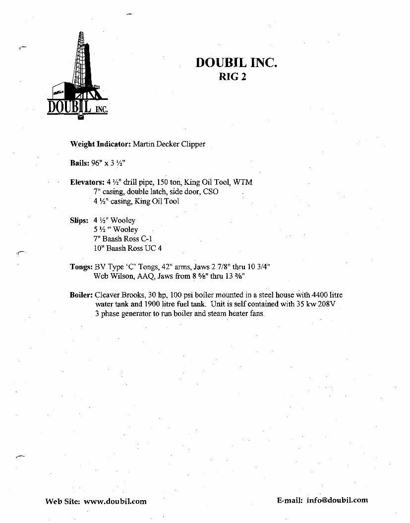
DOUBIL INC. RIG2
Weight Indicator: Martin Decker Clipper
Bails: 96" x 3 1/2"
Elevators: 4 '/2" drill pipe, 150 ton, King Oil Tool, WTM 7" casing, double latch, side door, CSO 4 '/2" casing, King Oil Tool
Slips: 4 '/z" Wooley 5 '/2 " Wooley 7" Baash Ross C-1 10" Baash Ross UC 4
Tongs: BV Type 'C' Tongs, 42" arms, Jaws 2 7/8" thru 10 3/4" Web Wilson, AAQ, Jaws from 8 5/8" thru 13 3/8"
Boiler: Cleaver Brooks, 30 hp, 100 psi boiler mounted in a steel house with 4400 litre water tank and 1900 litre fuel tank. Unit is self contained with 35 kw 208V 3 phase generator to run boiler and steam heater fans.
Web Site: www.doubil.com E-mail: [email protected]

`riI• WT 300. BBL
• DOGI•iOl15E
rÎ YAicA c Let cost ~ o.J Sr24
KA) /i1 M
•
•
.44
i
1
1 1 1
1
-41
CASING RACKS CA,14.1-44 Rovr, .0/0
N.~c,~.w~~•c 7R.9ikRrt ► '
NORTii
v ~ 1
~ L].1
~ O
LJ 17~
RIG #2 SCALE I "= 20'0'
jjc?et'u. rT•tC —77kA rt. Edri ia Tr/rC /4+QE.A CUPIAJAR. rpo1.
• RIG
SOAP TANK
FUEL TANK
▪ SUB ',FLOOR
I I0' Typical
1
CENTRE TUB
MILD PUMP #2
BOOSTER
PRIMARY AIR
RAMP I-
MUD TANK 300 BBL
53' Typical ~------•~{
levy* Qom ae,40.,y-AA
RINK TUB'
COLLAR TUB
BRINE TANK 300 BBL ~
MUD PUMP if • i
PIPE TUB, (41h)
PIPE TUB (4'h)
PRIMARY AIR
:Gal HOUSE