drill bit operation manual for the oil and gas industry
TRANSCRIPT

vbm.ru Page 1
Oil and gas industry
DRILL BIT
OPERATION MANUAL
FOR THE OIL AND GAS INDUSTRY
Oil and gas industry
vbm.ru Page 2
OPERATING PROCEDURE
Of using Volgaburmash and Uralburmash drill bits at different stages from drilling through casing elements to pulling the bit to the surface, including optimizing bit operational parameters and troubleshooting.
PACKING AND TRANSPORTATION
Reasonable precautions should be taken in the course of transportation of the bits. At the plant, the bit is packed into a wooden or cardboard box to prevent its damage during transportation process. The bit has to remain packed until it is used. Dropping packaged bits is prohibited. When a bit is moved without package, it is necessary to place a wooden or rubber pad under the bit face. It is also necessary to avoid hitting thread connection. Remember that PDC bits weight more than roller cone bits of the same diameter.
BITS STORAGE
• Bits should be kept in conditions preventing immediate contact of the package and the product in it with any moisture sources, including atmosphere precipitation. If bits are kept indoors, control of relative air humidity and temperature is required.
• It is not recommended to keep sealed bearing bits at low temperatures. You should also avoid sudden changes in temperature as it can affect seal life.
• Drill bits must be stored and transported in factory package strictly observing correct vertical orientation of the package (bits should be kept with their pins upwards). Stowing and fastening of goods as well as loading and unloading should ensure safety of the package during transportation and relocation.
• On the drill rigs, drill bits must be stored in factory packaging. If kept without original package, bits should be kept with their pins upwards in line with measures to ensure mechanical protection of the thread and protection of bits against humidity and atmosphere precipitation.

Oil and gas industry
vbm.ru Page 3
PRE-OPERATIONAL PHASE
• Preparation of a bit is carried out on the drill site, after the previous bit is pulled out. When pulling out a bit, check if there are tight sections in the borehole. If a tight section is revealed, ream the borehole to avoid problems further on.
• After pulling out the bit, describe its wear. Pay special attention to the broken or lost teeth (cutters), broken or lost nozzles, broken blades, broken or lost cones, any mechanical damages. If there are any metal fragments in the well, there is a danger of damaging a new bit when it starts therefore it is recommended to use the tool for cleaning the bottom-hole.
• When a new bit is prepared, the rotary table should be covered. For a roller cone bit, you may use a bit breaker, for a PDC bit, you may use a wood panel or screen fully covering the well mouth. Fix the bit breaker to a PDC bit before placing it to the table. Take precautions when lifting a bit.
• Make sure that connecting thread is covered with grease.
• Make-up torque should be selected according to the thread size and type.
Lifting heavy objects
RECOMMENDED TORQUE
Connecting thread Torque recommended, kN/m GOST API
З-50 - 2,1 – 2,4
З-66 2 3/8 4,0 – 4,8
3-76 2 7/8 6,0 – 7,5
З-86 NC 31 9,6 – 11,6
З-88 3 1/2 9,5 – 12,0
З-117 4 1/2 16,0 – 22,0
З-133 NC 50 15,0 – 17,0
З-152 6 5/8 38,0 – 43,0
З-177 7 5/8 46,0 – 54,0

Oil and gas industry
vbm.ru Page 4
OPERATIONAL PHASE
RUN-IN-HOLE OPERATION
• when the bit is made up, carefully, avoiding shocks run the bit through rotary table into the umbrella and assembly of blow-out preventers. Remember that hole rugosity and shoulders are dangerous for PDC cutters. Inside the casing such places are the conductor and drilled out casing shoe, in the open hole there can be shoulders, sharp variations of the hole trajectory, tight sections. BHA stiffness is also important.
• Smoothly run the drill string into the open hole without slacking off or relief more than 5 tons. Ream the tight sections and hole shoulders if necessary.
• If a significant part of the borehole should be reamed, it is recommended to use a roller cone bit instead of a PDC bit.
• The last drill pipe stand should be run in the hole at limited speed. If BHA relief is more than 5 tons you should lift up the bit, start the mud pump, clean the well for 10-15 minutes and with normal mud circulation run the bit to the bottom hole while reaming bottom hole area.
• You should remember that when reaming, a PDC bit is apt to lateral vibrations which may result in the damage of cutters.
REAMING AND HOLE-OPENING IN PREVIOUSLY DRILLED SECTIONS
• Ream the bore hole at low WOB and RPM.
• Circulation rate should be maximal allowed.
• When reaming in the sections with hard and abrasive formations, RPM should be reduced.
• For rotary drilling, use WOB = 0.5-2.5 tons and RPM = 40 – 60rpm.
• When drilling with downhole motors, use similar mode of minimal WOB and minimal circulation rate allowed.
• When drilling the bore hole, WOB is not recommended to be higher than 2 tons to avoid damaging the cutting structure.
• Control the torque when reaming in sections with abrasive formations. The torque mainly increases when PDC cutters on the gauge are seriously worn or a roller cone bit loses its diameter which results in bit body or BHA elements contacting the bore hole walls.
DRILLING OUT
Methods of drilling out shoe tracks (ST) and casing hardware with PDC or roller cone bits do not differ a lot. To prevent bit damage, please follow the recommendations below:
• Shoe tracks (ST) and cement plugs are drilled out with maximal circulation rate possible and minimal WOB.
• During ST drilling out, drill string is reciprocated from time to time which facilitates bit cleaning from cuttings.
Reciprocation should take place every 5-10 minutes of drilling or every 5-10 cm drilled per 1-1.5 m of the kelly. If ROP suddenly drops, repeat this procedure until the bottom hole and the bit are fully cleaned.
• Monitor pipe pressure to avoid plugged nozzles.
• Modify RPM if vibrations occur or torque suddenly leaps.

Oil and gas industry
vbm.ru Page 5
• If a cement plug turns over, try to relieve the drill string onto it without rotation. Increase WOB or circulation rate (pipe pressure should increase by 15-20 atm.). Start rotating the drill string at 40 – 60 rpm. Repeat this procedure till you are sure that the plug is broken.
FORMING NEW BOTTOM HOLE PROFILE AND BIT BREAKING IN
• When starting work with a new bit, it is important to form the new bottom hole profile according to the bit geometry. The bit efficiency and ROP depend on this quality of this procedure.
• You should be especially careful when forming the bottom hole profile, if geometry and type of the new bit differ essentially from the previous one – a PDC bit after a roller cone bit or vice versa.
• You should remember that a roller cone bit usually makes a larger hole diameter than a PDC bit
• 1.5 – 2 meters above the estimated bottom hole, start mud circulation with a predetermined optimal rate. Recommended RPM = 40 – 60.
• Increase of counter torque and WOB indicates reaching the bottom hole. WOB should be limited to 2 tons.
• After reaching the bottom hole, the tool should be lifted up to 15 – 30 cm above the bottom hole and the bottom hole should be cleaned for 5 minutes to remove the pad of cuttings.
• Then return to the bottom hole and start drilling with WOB not exceeding 2 tons. Maintain this load while drilling the distance equal to the length of the bit.
• Maintain minimal and steady torque of the bit.
• Continue the part load mode chosen to form the new bottom-hole profile till the bit runs the distance equal to the length of the bit. Then you may switch to the mode with optimal parameters.

Oil and gas industry
vbm.ru Page 6
DRILLING
Operating parameters and drilling modes of roller cone and PDC bits are indicated in the bit passports. Particular operating parameters of the bits are always defined according to lithology information and well engineering data.
• In soft formations, the highest possible RPM and relatively low WOB are recommended.
• In medium formations, medium WOB should be maintained at medium RPM. With wear of the cutters, it is recommended to increase WOB.
• In hard formations, the most efficient is the drilling mode with medium to high WOB and low to medium RPM.
• It is not recommended to apply the top values of all drilling parameters at the same time. Drilling parameters are indicated in a bit specification.
• Avoid WOB drops as supplying the load jerkily by 3-5 tons results in steep increase of torque on the bit which in turn leads to pipe pressure jumps and motor shutdown, it may also result in bit balling.
• To determine WOB in the vertical bore hole, before you start drilling, you should measure the bit’s hook weight with pumps on. In high ROP applications, the bit’s hook weight should be measured while the drill string is being run down to the bottom hole with estimated ROP. This is because the true WOB may be lower than the measured weight of the bit by the value of hydraulic lift (with pumps on) applied from under the bit. Hydraulic lift has an effect on any bit type which creates differential pressure due to fluid flow between the tool face and the rock.
• For directional or horizontal bore hole optimum WOB is defined by differential pressure (injection pressure difference when the bit is “on bottom hole” and “above bottom hole”). Recommended minimum differential pressure is 20 atm. When drilling remember to control WOB by means of stand pipe differential pressure maintenance.
• When using downhole motors, all other things being equal, bit performance indicators are governed by the technical condition of the motor. That is why before BHA is run down the hole, please check the actual technical parameters of the motor which are defined by means of benchmark tests after each repair work. Benchmark test results are indicated in the bit certificate, including moment of force at the output shaft (in operating mode and in full power condition); output speed (in no-operation mode, in operation mode and at maximum feed allowed); differential pressure of the motor (in no-operation mode, in operation mode and in braking mode).
OPTIMIZING DRILLING PARAMETERS
Two test requirements:
• Conducting a test is only possible after the bit breaking in;
• The formation is relatively homogeneous.
Passive test:
• Haul WOB to zero, to avoid hanging up of the tool.
• With medium RPM, create maximum WOB allowed and fix the travelling block.
• Constantly register changes of WOB, write down the time it takes to reduce WOB (hook weight increases) by a certain value (for example, by 2 tons) depending on bit diameter and type.
• Continue record of time periods it takes to decrease WOB by identical values until ROP doesn’t become considerably less in comparison with the beginning of the test.

Oil and gas industry
vbm.ru Page 7
• Evaluate WOB, changing of which by the set value took the shortest time. This WOB is optimum for this RPM.
• Repeat the test for other RPM values up to the maximum allowed (for the bit and the drive).
• Values at which time to reduce WOB by a certain value will be the smallest will be an optimum combination of RPM and WOB.
• The passive test can be stopped if after WOB is applied it does not decrease. It can be indicative of insufficient WOB supply.
Active test:
• Set the average optimum bit RPM.
• Set the lower level of WOB based on the optimum range and record ROP during 5 minute interval.
• Record ROPs several times, each time applying greater WOB.
• Repeat this till you reach the upper level of optimum range of WOB.
• Identify the range of parameters at with maximum ROP.
• Repeat the test several times with various WOB values.
• After optimum WOB value is identified by means of its increase and decrease, ROP can be optimized.
TROUBLESHOOTING
Bit life directly depends on compliance with the recommended operational modes indicated in the bit specification, nevertheless, for a number of reasons, the bit can fail before the estimated run life, therefore it is very important to assess the problem in due time and to make recommendations on its solution, i.e. to carry out troubleshooting.
On the surface, the following parameters can be indicative of a failure:
• Pressure
• Torque
• RPM
• Axial loading
• Flow rate
• ROP
• Vibration
• Rock samples
Each of the listed signs of malfunction can be caused by several factors. Some factors are very specific. Carefully study the issue and pass to stage-by-stage elimination of its reasons.
Change of working pressure
PDC bit
• Bit balling
• Mud ring in the annulus
• Flow rate change
Roller cone bit
• Bit balling
• Flow rate change
Oil and gas industry
vbm.ru Page 8
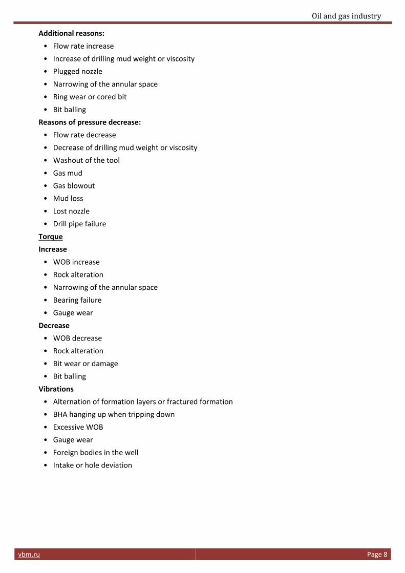
Additional reasons:
• Flow rate increase
• Increase of drilling mud weight or viscosity
• Plugged nozzle
• Narrowing of the annular space
• Ring wear or cored bit
• Bit balling
Reasons of pressure decrease:
• Flow rate decrease
• Decrease of drilling mud weight or viscosity
• Washout of the tool
• Gas mud
• Gas blowout
• Mud loss
• Lost nozzle
• Drill pipe failure
Torque
Increase
• WOB increase
• Rock alteration
• Narrowing of the annular space
• Bearing failure
• Gauge wear
Decrease
• WOB decrease
• Rock alteration
• Bit wear or damage
• Bit balling
Vibrations
• Alternation of formation layers or fractured formation
• BHA hanging up when tripping down
• Excessive WOB
• Gauge wear
• Foreign bodies in the well
• Intake or hole deviation

Oil and gas industry
vbm.ru Page 9
ROP
Rop increase
• Rock alteration
• Mud weight decrease or properties improvement
• Pore pressure increase
• WOB optimization
• RPM optimization
• Cleaning (hydraulics) optimization
Rop decrease
• Rock alteration
• Mud weight increase or properties deterioration
• WOB is not optimized
• RPM is not optimized
• Poor bit cleaning (hydraulics)
• Worn cutting structure
Rop variations
• Alternation of formation layers or fractured formation
• Bit balling
• Lack of BHA movement
FLOW RATE
Flow rate increase at constant pump pressure
• Washout of the tool
• Gas mud
• Gas blowout
• Mud loss
• Decrease of drilling mud weight or viscosity
Flow rate decrease at constant pump pressure
• Narrowing of the annular space
• Plugged nozzle or washing groove
• Bit balling
• Increase of drilling mud weight or viscosity
• Ring wear or cored bit
REMOVAL OF BIT BALLING AND STICKING CLAY
In soft hydrophilic clay when using water based mud, clay hydration and sticking to the bit are likely to occur which results in drop of drilling efficiency.
Balling symptoms are:
• significant drop of torque,
• significant drop of ROP,
• increase of pipe pressure.

Oil and gas industry
vbm.ru Page 10
For cleaning the bit the following steps should be taken:
• Lift the bit by 5 cm (2in) above the bottom hole.
• Inject the mud at maximum rate allowed for 5 – 15 minutes.
• While doing that, increase bit RPM to the maximum possible for 1 minute, repeat this step a 1 minute intervals.
• After the specified procedure, set new drilling parameters:
1. Set maximum possible RPM.
2. Set maximum possible flow rate.
3. Set WOB value at 80% of the value at which bit balling occurred.
Remember that to identify the main reason of a failure it is necessary to check several parameters.
DRILL BIT PULL OUT
Drill bit pull out is caused by several reasons:
• Reaching the target depth
• Specified section
• Changing the bit or other downhole tools with the change of formations
• In case of directional drilling, reaching severe dog leg or change of formations
• In case of core sampling – reaching the target depth or formation
• Sudden increase or decrease of torque for no apparent cause
• Lateral or torsional vibrations
• Sudden drop of ROP.
DRILL BITS DULL GRADING
Evaluation parameters
Cutting structure Bearing Bit
diameter Comments
Inner rows Outer rows Dull
characteristics Location Bearings / Seals
Gauge wear 1/16
Other dull characteristics
Reason pulled
(I) (o) (D) (L) (B) (G) (O) (R)

Oil and gas industry
vbm.ru Страница 11
(I) Inner rows (2/3 of the bit diameter)
(o) Outer row
Columns (I) and (o) describe cutting structure condition linear scale 0 - 8
For milled teeth bits:
Measuring tooth height reduction due to abrasive wear or chipping
0 – tooth is not worn
8 – wear out
For TCI bits:
Counting lost, worn out or chipped inserts
0 – no lost, worn out or chipped inserts
8 – all inserts are worn out, chipped or lost
For PDC bits:
Counting lost, worn out or chipped cutters
0 – no lost, worn out or chipped cutters
8 – all cutters are worn out, chipped or lost
(D) Dull characteristics
Only applied to cutting structure
*BC – Broken Cone
BF – Bond Failure
BT – Broken cutters/Teeth
BU – Balled Up
*CC – Cracked Cone
*CD – Cone Dragged
CI – Cone Interference
CR – Cored
CT – Chipped Cutters
ER – Erosion
FC – Flat Crests of Steel Teeth
HC – Heat Checking
JD – Junk Damage
*LC – Lost Cone
LN – Lost Nozzle
LT – Lost Cutters
OC – Off-Center Wear
PB – Pinched Bit
PN – Plugged Nozzle/Flow Passage
RG – Rounded Gauge
RO – Ring Out
SD – Shirttail Damage
SS – Self-Sharpening
TR – Tracking
WO – Washed Out
WT – Worn Cutters
NO – No Wear
Oil and gas industry
vbm.ru Страница 12
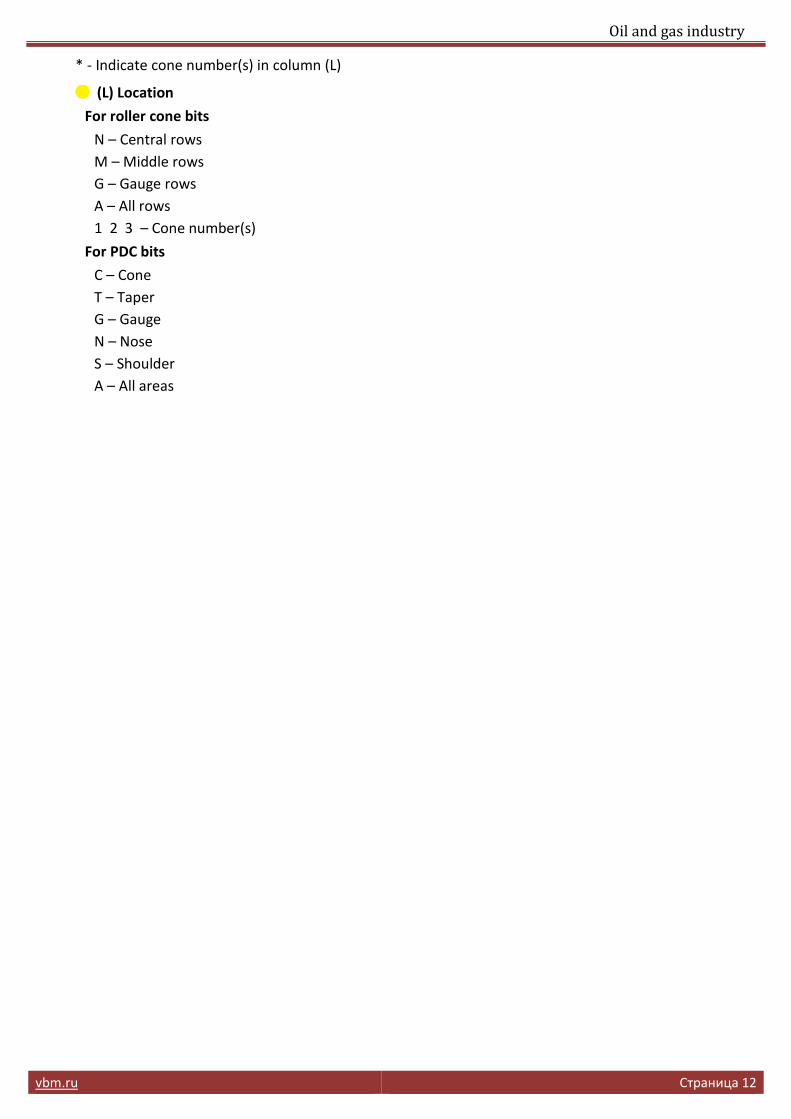
* - Indicate cone number(s) in column (L)
(L) Location
For roller cone bits
N – Central rows
M – Middle rows
G – Gauge rows
A – All rows
1 2 3 – Cone number(s)
For PDC bits
C – Cone
T – Taper
G – Gauge
N – Nose
S – Shoulder
A – All areas

Oil and gas industry
vbm.ru Страница 13
(B) Bearings/seals
Open bearing – linear scale from 0 to 8 describes bearing service life
0 – bearing capacity is not used
8 – bearing capacity is fully used
Sealed bearing
E – Seals are not damaged
F - Seals damaged
N – it is not possible to assess wear
X – PDC bit, no bearing
(G) Gauge
I – In Gauge
1/16 – 1/16” Out of Gauge
1/8 – 1/8” Out of Gauge
1/4 – 1/4” Out of Gauge
(О) Other dull characteristics (See column D)
(R) Reason pulled
BHA – Change Bottom Hole Assembly
DMF – Downhole Motor Failure
DTF – Downhole Tool Failure
DSF – Drill String Failure
DST – Drill Stem Test
DP – Drill Plug
CM – Condition Mud
CP – Core Point
FM – Formation Change
HP – Hole Problems
LIN – Left in Hole
HR – Hours on Bit
LOG – Run Logs
PP – Pump Pressure
PR – Penetration Rate
RIG – Rig Repair
TD – Total Depth
TW – Twist Off
TQ – Torque
WC – Weather Conditions