dredging & reclamation management plan · dredging & reclamation management plan . project...
TRANSCRIPT

Dredging & Reclamation Management Plan Project Name : Design and Construction of Onslow Marine Supply Base
Project Location : Onslow, Western Australia
Client : Onslow Marine Support Base (OMSB)
Contract No : DnC OMSB Contract 20161116
Internal No. : MCE.0455
Prepared by:
Document No. MCE0455_PMP_011
Document Title Dredging & Reclamation Management Plan
Rev. Date Issue type Originator Review Approval
A 25.08.2016 Issued For Review S Watkins S Fielder I Lambay
B 21.09.2016 Issued For Review S Watkins BMTO I Lambay
C 23.11.2016 Issued for Approval S Watkins BMTO BMT JFA
I Lambay
0 07.12.2016 Issued for Construction S Watkins I Lambay I Lambay

Document Number MCE0455_PMP_011 Document Name Dredging & Reclamation Mgmt Plan
Project Onslow Marine Support Base Date of Issue 07 December 2016
Client OMSB Revision 0
2 of 31
Table of Contents 1 Introduction .............................................................................................................................................. 4
1.1 General ............................................................................................................................................ 4
1.2 Project Background ......................................................................................................................... 4
2 References ............................................................................................................................................... 5
2.1 Client and/or Contract specific procedures, documents, standards ............................................... 5
2.2 Maritime Constructions’ (project specific) procedures, documents, standards .............................. 5
2.3 Acts, Regulations, Codes of Practice and Australian Standards .................................................... 6
3 Definitions & Abbreviations ...................................................................................................................... 7
4 Outline of Project ..................................................................................................................................... 8
4.1 Project Identification ........................................................................................................................ 8
4.2 Milestones ....................................................................................................................................... 8
4.3 Construction Program ..................................................................................................................... 9
4.4 Site Lay-Out .................................................................................................................................... 9
4.4.1 Marine Activity Zone .................................................................................................................... 9
4.4.2 Land Operations ........................................................................................................................ 10
5 Project Setup ......................................................................................................................................... 11
5.1 General .......................................................................................................................................... 11
5.2 Mobilisation ................................................................................................................................... 12
5.3 Site Setup ...................................................................................................................................... 12
5.3.1 Construction of Swale and Bund Walls ..................................................................................... 13
5.3.2 Pipeline ...................................................................................................................................... 13
6 Detailed Method of Working .................................................................................................................. 14
6.1 Dredging by Cutter Suction Dredge .............................................................................................. 14
6.1.1 Cutter Suction Dredge (CSD) General Process ........................................................................ 14
6.1.2 Dredge Area and CSD Sequencing .......................................................................................... 16
6.1.3 Bulk Dredging ............................................................................................................................ 16
6.1.4 Dredging of Low Concentration TBT’s ...................................................................................... 17
6.1.5 Dredging of High Concentration TBT’s ..................................................................................... 19
6.2 Reclamation Activities ................................................................................................................... 22
6.2.1 Spreading Area-A Dredged Material ......................................................................................... 22
6.3 Clean-up Dredging ........................................................................................................................ 24
6.3.1 Dragflow Dredge ....................................................................................................................... 25
6.3.2 Long Reach Excavator .............................................................................................................. 25
6.4 Process Control ............................................................................................................................. 27
6.5 Tolerances / Acceptance Criteria .................................................................................................. 27
6.6 Demobilisation ............................................................................................................................... 28
7 Resources .............................................................................................................................................. 29
7.1 Assigned Equipment ..................................................................................................................... 29

Document Number MCE0455_PMP_011 Document Name Dredging & Reclamation Mgmt Plan
Project Onslow Marine Support Base Date of Issue 07 December 2016
Client OMSB Revision 0
3 of 31
8 Risk Management .................................................................................................................................. 30
8.1 Project Management Plans ........................................................................................................... 30
8.2 Environmental Management ......................................................................................................... 30
8.3 Quality Control............................................................................................................................... 30
8.3.1 Non-conformance ...................................................................................................................... 31
8.4 Reporting ....................................................................................................................................... 31
Table of Figures Figure 1 - OMSB Proposed Development Area .............................................................................................. 4 Figure 2 Marine Activity Zone ....................................................................................................................... 10 Figure 3 : Land activity zone ......................................................................................................................... 10 Figure 4 : Overview of Sit – showing Dredge Area (Red) and Reclaim area (Green) .................................. 11 Figure 5 : Site Layout Plan for commencement of CSD Dredging ............................................................... 12 Figure 6: Principles of bund construction ...................................................................................................... 13 Figure 7: Schematic overview of a Cutter Suction Dredge ........................................................................... 14 Figure 8 : Typical Dredge and Anchor Layout (in Plan) ................................................................................ 14 Figure 9: Graphical presentation of the movements of a CSD ..................................................................... 15 Figure 10: Dredge and Disposal Area for bulk dredging ............................................................................... 17 Figure 11 : Dredging Area B ......................................................................................................................... 18 Figure 12 : Dredging Area C and D .............................................................................................................. 19 Figure 13: Dredge and Disposal Area for TBT identified spoil ...................................................................... 20 Figure 14 : Geobag Laydown and water containment pond ......................................................................... 20 Figure 15: Site Plan during land reclamation phase ..................................................................................... 22 Figure 16 : Spreading and Placing Area-A materials, within the reclamation area and above HAT ............ 23 Figure 17: Site Plan during clean up dredging phase ................................................................................... 24 Figure 18: Submersible Dragflow Cutter/Pump ............................................................................................ 25 Figure 19: Long Reach Excavator Kobelco SK260 ...................................................................................... 26 Figure 20: Wharf and lay down area, after clean up dredging ...................................................................... 26 Figure 21: Sample Screen Print of Dredgepack software ............................................................................. 27

Document Number MCE0455_PMP_011 Document Name Dredging & Reclamation Mgmt Plan
Project Onslow Marine Support Base Date of Issue 07 December 2016
Client OMSB Revision 0
4 of 31
1 Introduction 1.1 General This document describes the intended working method for the dredging and reclamation of Beadon Creek river sediments for the Onslow Marine Support Base (OMSB) Project in Onslow (WA) as further described in the Contract between Onlsow Marine Support Base Pty Ltd and Maritime Constructions Pty Ltd. 1.2 Project Background Beadon Creek is a tidal inlet on the eastern side of the coastal town of Onslow, 1,390km north of Perth. The current Beadon Creek maritime facility is located approximately 550m south of the entrance to Beadon Creek and provides boating facilities for commercial fishing vessels, charter vessels, tugs, barges and recreational vessels. The Beadon Creek Maritime Facility is also regionally important for providing cyclone refuge for vessels along the Pilbara coast. The maritime facility in Onslow was originally designed for recreational, fishing and charter operations. However, extensive growth of the resources sector in the Pilbara region has led to increased demand for maritime support services and industries. As a result, the Department of Transport (DoT) released more land at the facility for development. The Onslow Marine Support Base will include the construction of a 204m of new wharf frontage, a single heavy lift crane-pad, laydown and car park facilities and the capital dredging of a berth pocket and turning basin immediately west of the existing channel. The dredged material will be used to create an additional land-backed wharf area immediately north of the existing lots. This capital dredging requires approximately 55,000 m3 of material to be reclaimed.
Figure 1 - OMSB Proposed Development Area

Document Number MCE0455_PMP_011 Document Name Dredging & Reclamation Mgmt Plan
Project Onslow Marine Support Base Date of Issue 07 December 2016
Client OMSB Revision 0
5 of 31
2 References Reference in this Management Plan is made to the latest revision of the following documents: 2.1 Client and/or Contract specific procedures, documents, standards
REFERENCE DOCUMENT DESCRIPTION
LOI Letter of Intent – Agreement for the Design and Construction of the Onslow Marine Supply Base, Lot 13 Beadon Creek, Onslow, Western Australia, dated 04 July 2016
CONTRACT Contract No. Design and Construction of Onslow Marine Support Base 20161116 – including the Principal’s Project Requirements
DEIA Beadon Creek Maritime Facility, Capital Dredging Environmental Impact Assessment; BMT Oceania, 365_01_004/1_Rev6, April 2014
OEPA Notice EPA Public Advice ref 13-283104 dated 28 April 2014
Notification of Dredging Department of Transport Memorandum to the Office of the EPA notifying the commencement of capital dredging in Beadon Creek, dated 31/10/2016
2.2 Maritime Constructions’ (project specific) procedures, documents, standards
REFERENCE DOCUMENT DESCRIPTION
MCE0455_PMP_001 Construction Management Plan
MCE0455_PMP_002 Safety Management Plan
MCE0455_PMP_003 Environment Management Plan
MCE0455_PMP_004 Water Quality Monitoring Plan
MCE0455_PMP_005 Vessel Safety Management Plan (Ngurunderi)
MCE0455_PMP_006 Vessel Safety Management Plan (Carter)
MCE0455_PMP_007 Cyclone Management Plan
MCE0455_PMP_008 Employee Relations Management Plan
MCE0455_PMP_009 Site Organisation Chart
MCE0455_PMP_010 Site Induction
MCE0455_PMP_011 Dredging and Reclamation Management Plan
MCE0455_PMP_012 Communication Management Plan
MCE0455_WMS_001 Wharf Construction (Work Method Statement)
MCE0455_ITP_001 Inspection and Test Plan - Wharf Construction
MCE0455_ITP_002 Inspection and Test Plan - Dredging and Land Reclamation
MCE0455_PRM_001 Project Construction Program
MCE0455_PRA_001 Project Risk Assessment

Document Number MCE0455_PMP_011 Document Name Dredging & Reclamation Mgmt Plan
Project Onslow Marine Support Base Date of Issue 07 December 2016
Client OMSB Revision 0
6 of 31
2.3 Acts, Regulations, Codes of Practice and Australian Standards
Occupational Health and Safety
Western Australian Occupational, Health and Safety Act, 1984 (WA)
Occupational, Health and Safety Regulations, 1996 (WA)
Dangerous Goods Safety Act, 2002 (WA)
Australian Maritime Safety Authority Act, 1990 (Commonwealth)
Workers Compensation and Injury Management Act, 1982
Workers Compensation and Injury Management Regulations, 1982 (WA)
Western Australia Marine (Cert of Competency & Safety Manning) Regulations, 1983 (WA)
Building & Construction Industry Training Fund & Levy Collection Act, 1990 (WA)
Industrial Relations Act, 1979 (WA)
Environmental
Environmental Protection Act, 1986 (WA)
Environment Protection and Biodiversity Conservation Act, 1999 (Commonwealth)
Environmental Protection (Sea Dumping) Act, 1981 (Commonwealth)
Environmental Protection Regulations, 1987 (WA)
Environmental Protection (Unauthorized Discharges) Regulations, 2004 (WA)
Environmental Protection (Clearing of Native Vegetation) Regulations, 2004 (WA)
Western Australia Marine (Sea Dumping) Regulations, 1982 (WA)
Harbours and Jetties Act, 1928 (WA)
West Australian Marine Act, 1982 (WA)
Navigable Waters Regulations, 1958 (WA)
Aboriginal Heritage Act, 1972 (WA)
Conservation and Land Management Regulations, 2002 (WA)
Australian Standards
AS4997-2005 Guidelines for the Design of Maritime Structures
AS1657-1992 Fixed Platforms, Walkways, Stairways & Ladders – Design, Const. & Installation
AS2159-1995 Piling – Design and Installation
AS1554-2004 Structural Steel Welding (Parts 1 to 5) Maritime Constructions operates in accordance with Laws, Regulations and Australian Standards at all times.
Document Number MCE0455_PMP_011 Document Name Dredging & Reclamation Mgmt Plan
Project Onslow Marine Support Base Date of Issue 07 December 2016
Client OMSB Revision 0
7 of 31
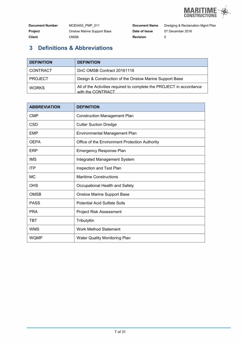
3 Definitions & Abbreviations DEFINITION DEFINITION
CONTRACT DnC OMSB Contract 20161116
PROJECT Design & Construction of the Onslow Marine Support Base
WORKS All of the Activities required to complete the PROJECT in accordance with the CONTRACT
ABBREVIATION DEFINITION
CMP Construction Management Plan
CSD Cutter Suction Dredge
EMP Environmental Management Plan
OEPA Office of the Environment Protection Authority
ERP Emergency Response Plan
IMS Integrated Management System
ITP Inspection and Test Plan
MC Maritime Constructions
OHS Occupational Health and Safety
OMSB Onslow Marine Support Base
PASS Potential Acid Sulfate Soils
PRA Project Risk Assessment
TBT Tributyltin
WMS Work Method Statement
WQMP Water Quality Monitoring Plan

Document Number MCE0455_PMP_011 Document Name Dredging & Reclamation Mgmt Plan
Project Onslow Marine Support Base Date of Issue 07 December 2016
Client OMSB Revision 0
8 of 31
4 Outline of Project 4.1 Project Identification Project
Name Design & Construction of Onslow Marine Support Base
Location Onslow, Western Australia
Contract No. DnC OMSB Contract 20161116
Contract Manager Imran Lambay
Project Manager Sam Watkins Engineering Consultant
Name Aztec Analysis Pty Ltd
Design Manager David McKay Client
Name Onslow Marine Support Base (OMSB)
Client’s Representative Andrew Natta 4.2 Milestones
Task Name Start Finish
Design and Construction of OMSB Mon 4/07/16 Mon 18/09/17
LOI Award Mon 4/07/16 Mon 4/07/16
Contract Negotiations Mon 4/07/16 Mon 14/11/16
Contract Award Wed 16/11/16 Wed 16/11/16
Preliminaries Mon 4/07/16 Fri 9/09/16
Design Mon 4/07/16 Fri 18/11/16
Procurement Wed 16/11/16 Wed 5/04/17
Mobilisation Wed 26/10/16 Fri 24/02/17
Execution Mon 5/12/16 Tue 22/08/17
Early Works Mon 5/12/16 Tue 14/02/17
Construction E - Dredging Mon 12/12/16 Fri 23/06/17
Construction A - Sheet Piling Fri 24/02/17 Mon 19/06/17
Construction B - Laydown Area Tue 20/06/17 Fri 21/07/17
Construction C - Crane Pads Fri 19/05/17 Thu 15/06/17
Construction D - LCT Ramp Wed 31/05/17 Fri 21/07/17
Construction F - Office Area Mon 24/07/17 Tue 8/08/17
Construction G - Miscellaneous Tue 20/06/17 Tue 22/08/17
Practical Completion Tue 22/08/17 Tue 22/08/17

Document Number MCE0455_PMP_011 Document Name Dredging & Reclamation Mgmt Plan
Project Onslow Marine Support Base Date of Issue 07 December 2016
Client OMSB Revision 0
9 of 31
4.3 Construction Program A Construction Program / Timeline has been prepared in Microsoft GANTT chart format. This program is a standalone document (MCE0455_PRM_001) and will be regularly updated during the course of the project. Each identified task has been defined in terms of duration and interdependencies, as well as the resources allocated to that task. Public holidays are included in the timeline as non-working days. Construction works will be performed on 21 days on 7 days off roster. Normal working times shall be Monday to Friday 7am – 7pm and Saturday & Sunday 7am – 6pm. All dredging and reclamation activities will be carried out on a full-continuous roster (24/7). 4.4 Site Lay-Out The overall site layout, to execute the works under this contract, will comprise of a Contractor’s site office and laydown area, a location for marine plant storm mooring and an on-water activity zone demarcating the areas that the floating plant will be operating, as detailed in the following sections. 4.4.1 Marine Activity Zone
The proposed on-water activity zone shown in Figure 2 below outlines the footprint of the on-water construction. Details of this proposed activity zone will be provided to Marine Safety, the Pilbara Port Authority and Maritime Constructions will issue a Notice to Mariners advising other Port users of works that may affect the safe navigation of vessels. Maritime Constructions will request Marine Safety to implement temporary vessel speed restrictions of 5 knots around this activity zone for the duration of these works for the safety of both construction crew and the general public. The purpose of the Marine Activity Zone (MAZ) will allow free and safe movement of construction floating plant during the course of the works. The MAZ is slightly larger than the dredging area footprint to allow for anchor positioning outside of the dredging area when dredging close to the boundaries of the footprint. The MAZ provides the pubic and all port users a clearly defined area to avoid, reducing navigational risks during the term of this project. However the MAZ will not be entirely occupied by floating plant during the works and only when navigational hazards such as anchors need to be located when operating close to the channel. This marine activity zone will be occupied by floating plant for a period of approximately 6-8 weeks, comprising of dredging activities performed by a cutter suction dredge, as well as during setup and demobilisation activities. An agreed VHF radio channel will be reserved for on-water marine works communication, based on standard marine communication protocols and alerts in case of emergencies. The station will serve as the means of communication between vessels. Other facility users, such as commercial and charter boat operators will also be provided with this VHF channel for communication with Maritime Constructions’ dredge operator and project supervisor should the need arise. The position of the cutter suction dredge will be controlled by anchors placed on the seafloor, comprising of a single stern anchor and 2 forward anchors. The planned position of all floating plant and anchors will be reported to the Harbour Master each day. Anchors will be clearly marked by ‘Special Marker’ buoys. The dredge anchors and pipeline will be marked with Norwegian buoys and white strobe lights. The cutter suction dredge will be operated and crewed 24 hours per day 7 days per week.

Document Number MCE0455_PMP_011 Document Name Dredging & Reclamation Mgmt Plan
Project Onslow Marine Support Base Date of Issue 07 December 2016
Client OMSB Revision 0
10 of 31
Figure 2 Marine Activity Zone
4.4.2 Land Operations
The land-based Contractor Activity Zone will be established on land, covering the entire site included in the works. The site is shown in Figure 3 below.
Figure 3 : Land activity zone

Document Number MCE0455_PMP_011 Document Name Dredging & Reclamation Mgmt Plan
Project Onslow Marine Support Base Date of Issue 07 December 2016
Client OMSB Revision 0
11 of 31
5 Project Setup 5.1 General The dredging and disposal works for the OMSB project consist of the capital dredging of a berth pocket to a declared depth of -2.6m CD. The materials will be removed by two methods of dredging at two distinct phases of the project;
Primary Dredging Phase; Using a Cutter Suction Dredge and hydraulically transported through a pipeline to the reclamation site.
Clean-up Dredging Phase; using Dragflow pump suspended from crane and/or by Longreach excavator
In general the project characteristics are as follows:
Characteristic Cutter Suction Dredging Campaign Clean Up Dredging Campaign
Activity Duration Approximately 2 months Approximately 1 month
Quantity to be dredged
Approximately 55,000m3 (including over-dredge quantity)
Approximately 15,000m3
(including over-dredge quantity)
Type of materials to be dredged
Silty sand
Silty sand
Main equipment CSD Ngurunderi, Carter AHV Kobelco Long Reach Excavator, Dragflow Pump suspended by crawler crane
Total length of pipeline
Approximately 800m (floating and landline combined)
Figure 4 below shows a schematic overview of the site.
Figure 4 : Overview of Sit – showing Dredge Area (Red) and Reclaim area (Green)
Document Number MCE0455_PMP_011 Document Name Dredging & Reclamation Mgmt Plan
Project Onslow Marine Support Base Date of Issue 07 December 2016
Client OMSB Revision 0
12 of 31
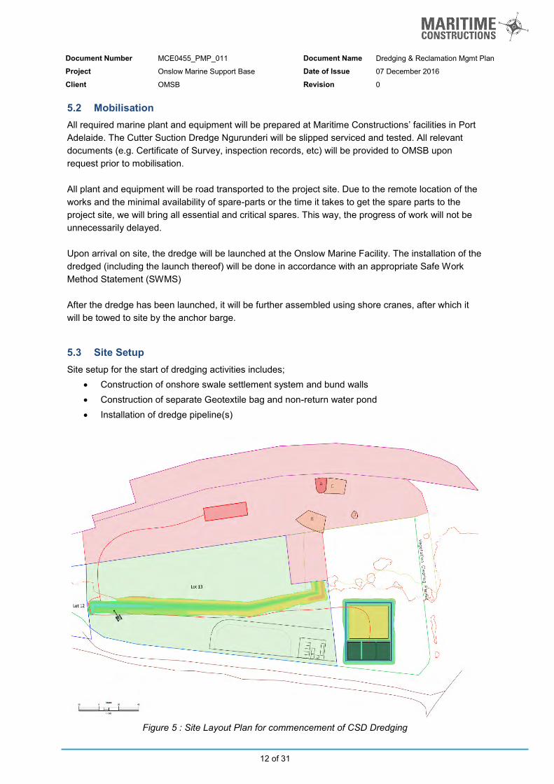
5.2 Mobilisation All required marine plant and equipment will be prepared at Maritime Constructions’ facilities in Port Adelaide. The Cutter Suction Dredge Ngurunderi will be slipped serviced and tested. All relevant documents (e.g. Certificate of Survey, inspection records, etc) will be provided to OMSB upon request prior to mobilisation. All plant and equipment will be road transported to the project site. Due to the remote location of the works and the minimal availability of spare-parts or the time it takes to get the spare parts to the project site, we will bring all essential and critical spares. This way, the progress of work will not be unnecessarily delayed. Upon arrival on site, the dredge will be launched at the Onslow Marine Facility. The installation of the dredged (including the launch thereof) will be done in accordance with an appropriate Safe Work Method Statement (SWMS) After the dredge has been launched, it will be further assembled using shore cranes, after which it will be towed to site by the anchor barge. 5.3 Site Setup Site setup for the start of dredging activities includes;
Construction of onshore swale settlement system and bund walls Construction of separate Geotextile bag and non-return water pond Installation of dredge pipeline(s)
Figure 5 : Site Layout Plan for commencement of CSD Dredging

Document Number MCE0455_PMP_011 Document Name Dredging & Reclamation Mgmt Plan
Project Onslow Marine Support Base Date of Issue 07 December 2016
Client OMSB Revision 0
13 of 31
5.3.1 Construction of Swale and Bund Walls
Inside the perimeter of the reclamation area, a swale system and bund walls will be constructed. Material for the bunds wall will be taken from within the reclamation footprint. The swale type design has been selected as this type of construction provides a large length for the flow of the dredge slurry to maximise the retention time of dredged spoil. This allows for heavy material to drop out to aid in dredge material harvesting, while still allowing the material to dry out for land reclamation by providing an opened end outflow at the downstream point of the bunds, without extensive ponding throughout the system. An outer bund wall will be constructed approximately at the existing HAT mark on the site, for secondary containment and for future stockpile protection. The swale and internal bund walls will be constructed from existing material on site, and the principles of the construction of the bund wall are shown in Figure 6 below.
Figure 6: Principles of bund construction
The construction of the reclamation bund walls will be by onsite excavator and done in accordance with a SWMS for Bund Wall Construction. 5.3.2 Pipeline
A pipeline with a diameter of 315mm will be used to transport the dredged material from the dredge to the reclamation area. The pipeline will partially be floating and land based, depending on the final alignment. These are approximately 400m in total length, as measured from the dredge.

Document Number MCE0455_PMP_011 Document Name Dredging & Reclamation Mgmt Plan
Project Onslow Marine Support Base Date of Issue 07 December 2016
Client OMSB Revision 0
14 of 31
6 Detailed Method of Working
6.1 Dredging by Cutter Suction Dredge
6.1.1 Cutter Suction Dredge (CSD) General Process
The bulk of the dredging works will be carried out by means of the CSD Ngurunderi. This is a stationary pontoon and consists of a U-shaped pontoon with a central ladder and is held in position by means of a 3-point mooring system.
Figure 7: Schematic overview of a Cutter Suction Dredge
The soil is loosened by rotating a cutting head (the “cutter”). The cutter head, which is hydraulically driven, encloses the suction intake of a centrifugal dredge pump. The cutter head is mounted at the extremity of the ‘ladder’, which is attached to the main hull by heavy hinges, enabling rotation in the vertical plane. The ladder assembly is lowered and raised by means of a hoisting winch controlled from the operator’s cabin. By means of winches, the cutter (and therefore the whole pontoon), is pulled in turns to the port and starboard side-anchor. In this way (part of) a circular movement is made. Forward movement of the dredge is controlled by releasing length of wire on the rear anchor, while simultaneously heaving wire in on the two forward anchors.
Figure 8 : Typical Dredge and Anchor Layout (in Plan)
Document Number MCE0455_PMP_011 Document Name Dredging & Reclamation Mgmt Plan
Project Onslow Marine Support Base Date of Issue 07 December 2016
Client OMSB Revision 0
15 of 31
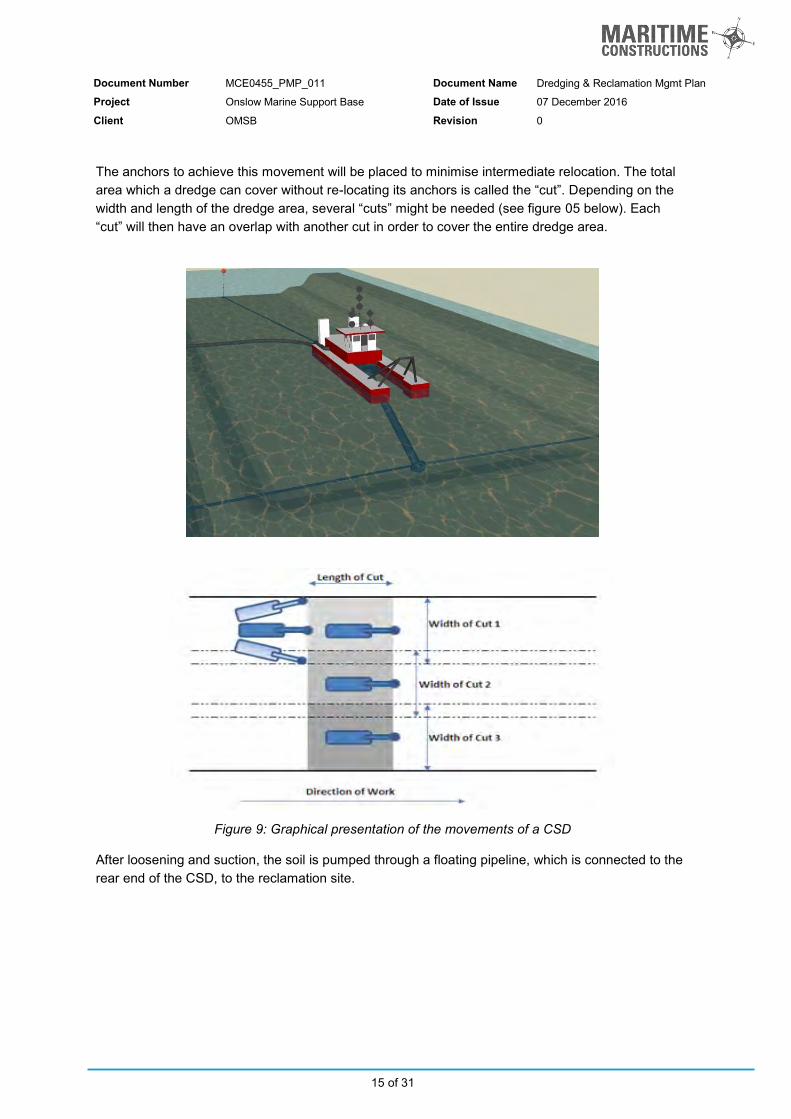
The anchors to achieve this movement will be placed to minimise intermediate relocation. The total area which a dredge can cover without re-locating its anchors is called the “cut”. Depending on the width and length of the dredge area, several “cuts” might be needed (see figure 05 below). Each “cut” will then have an overlap with another cut in order to cover the entire dredge area.
Figure 9: Graphical presentation of the movements of a CSD
After loosening and suction, the soil is pumped through a floating pipeline, which is connected to the rear end of the CSD, to the reclamation site.

Document Number MCE0455_PMP_011 Document Name Dredging & Reclamation Mgmt Plan
Project Onslow Marine Support Base Date of Issue 07 December 2016
Client OMSB Revision 0
16 of 31
6.1.2 Dredge Area and CSD Sequencing
For the purposes of this Dredging and Land Reclamation Management Plan, the dredging footprint has been divided into 5 key areas, as defined by the table below. Table 1 : Dredging Area Definition
Area Label Contamination Description Approx. Volume
A High TBT 75m3
B Low – Medium TBT 207m3
C Low – Medium TBT 292m3
D Low – Medium TBT 53m3
Undefined No identified TBT– remainder of dredging footprint 50,000m3
*volumes specified above are calculated based on contamination depth (A= 0.5m, B = 0.5m, C = 1.0m, D = 1.5m). Dredging will initially commence in the undefined ‘clean material’ zone to start the works. Water Quality Sampling will commence at the start of dredging works and will be performed daily for the first 14 days, as per the stand-alone Water Quality Monitoring Plan (MCE0455_PMP_004). Generally the sequence of the dredging by CSD will be;
1. Dredging undefined area – approx. 2 to 5 days 2. Dredging Low-Medium TBT contamination areas B, C, D (dredged to depth of contamination only)
– approx. 3 days 3. Dredging High TBT contamination area A (dredged to depth of contamination only) – approx. 1
days 4. Recommence dredging remaining undefined area – approx.3-4 weeks
6.1.3 Bulk Dredging
The bulk dredging will all be performed by means of the CSD. Both the dredging of the turning basin and the Berth Box will be done to achieve a depth of -2.6m CD with a maximum volume to be removed of not more than 55,000m3. The bulk dredging of the undefined dredging areas will be performed as and when required throughout the dredging campaign. As above, the first dredging activities will be the performed in bulk dredge area and, after the removal of contamination risk material, the remainder of the dredging will be performed by the method described in below. These activities are described generally and will be further detailed as per a specific Cut Plan and further described in a Safe Work Method Statement for Dredging by CSD.

Document Number MCE0455_PMP_011 Document Name Dredging & Reclamation Mgmt Plan
Project Onslow Marine Support Base Date of Issue 07 December 2016
Client OMSB Revision 0
17 of 31
Figure 10: Dredge and Disposal Area for bulk dredging
Dredged material will be dredged and pumped into the start of the swale bund and an excavator will maintain bund-walls and progressively install additional lengths of shore pipeline to allow for continuous dredging and sand harvesting As above, the swale bund area will not be closed and will allow water to free-flow out from the south-eastern end of the site and such that ponding cannot occur. This will allow sand material to drop out from the discharge slurry close to the outfall point. Sand will then be harvested from close to the outfall point by excavator and placed in a high sand stockpile to mass store the material and to allow it to sufficiently dry out. The swale will be a dynamic system and manipulation by excavator or other mechanical plant will allow the flow to be directed to suit the reclamation process, continue to maximise the flow path and material settlement, and minimise turbidity throughout the dredging campaign. 6.1.4 Dredging of Low Concentration TBT’s
Three areas within the dredging footprint, Areas B, C and D, have been identified as containing TBT contamination with a concentration that is acceptable to be managed by dilution from the dredging process. As with the undefined areas, these areas will be dredged by CSD into the onsite swale, however the dredge will pump at a fixed low solids concentration to sufficiently dilute any potential contamination in the dredge slurry. The target depth and solids concentration in the dredge slurry for each area will be per the following;
Area B to be dredged to 0.5m from natural level at 5% or less (sediments in dredge slurry)
Area C to be dredged to 1.0m from natural level at 10% or less (sediments in dredge slurry)
Area D to be dredged to 1.5m from natural level at 16% or less (sediments in dredge slurry)

Document Number MCE0455_PMP_011 Document Name Dredging & Reclamation Mgmt Plan
Project Onslow Marine Support Base Date of Issue 07 December 2016
Client OMSB Revision 0
18 of 31
The material that is dredged from these areas will be harvested and placed as part of the reclamation process. This is described below by Figure 11 and Figure 12.
Figure 11 : Dredging Area B
The control of the dredge solids concentration will be by using the dredge-pump flow rate and volume of in-situ material removed.
Pumping flow rate, and hence total slurry volume for a given time frame, will be determined by the on-board flowrate monitoring equipment. The solids volume will be calculated by determining dredged volume from the CSD Dredgepack software. The Dredgepack software creates a real-time bed surface profile during dredging, and using the pre-dredge survey the volume of in-situ material removed can be determined. Using the in-situ volume calculation and total flow over a given timeframe, an average slurry concentration will be determined, recorded and provided as part of the Water Quality Monitoring report to DoT on a weekly basis.
This process will also be performed and calibrated at the start of dredging onsite in the undefined ‘clean material’ areas (bulk dredging).

Document Number MCE0455_PMP_011 Document Name Dredging & Reclamation Mgmt Plan
Project Onslow Marine Support Base Date of Issue 07 December 2016
Client OMSB Revision 0
19 of 31
Figure 12 : Dredging Area C and D 6.1.5 Dredging of High Concentration TBT’s
Reference is made to the Department of Transport Memorandum to the Office of the EPA notifying the commencement of capital dredging in Beadon Creek, dated 31/10/2016 and the original DEIA for the Capital Dredging of Beadon Creek (BMTO and BMTJFA, 2014) with respect to the Beadon Creek Capital Dredging and Construction of Land-Backed Wharf, which describes the advice to dredge and discharge the materials from the area identified to have possible remnants of Tributyltin (TBT) as a separate priority The top 0.5m of the Area-A dredging area is considered to be at risk to contain remnants of TBT and as such, MC will develop a dredge Cut-Plan to control the dredging of this the identified area. A method of dredging into Geotextile bags (for containing the solid material) and separating the supernatant water (into a containment pond) has been selected due to its benefits, namely;
Separation of potentially contaminated solids and return-water for testing and later disposal
Drying and convenient storage of solid material removed from Area-A for later spreading into the reclaim area. Area A sediments will be spread into the laydown above HAT level, but also below finished level – i.e. capped with a clean material layer.
Maximising the water-holding capacity of the containment pond by removing the solid component of the dredged slurry – and storing ‘dry’ with a minimum footprint

Document Number MCE0455_PMP_011 Document Name Dredging & Reclamation Mgmt Plan
Project Onslow Marine Support Base Date of Issue 07 December 2016
Client OMSB Revision 0
20 of 31
Figure 13: Dredge and Disposal Area for TBT identified spoil
Figure 13 shows the dredge area for the Berth Box as well as the area identified to contain high risk levels of TBTs – Area A - and only this area will be dredged with full containment of return water. The Area A material will be dredged and pumped into Geotextile Bags in the specially designed and constructed containment pond and GeoBag laydown area, located in Lot 14 Beadon Creek, to the South of the OMSB development site. The material will be dewatered and stored in the GeoBags for containment and future spreading as a capped layer in the laydown area.
Figure 14 : Geobag Laydown and water containment pond
Document Number MCE0455_PMP_011 Document Name Dredging & Reclamation Mgmt Plan
Project Onslow Marine Support Base Date of Issue 07 December 2016
Client OMSB Revision 0
21 of 31
The GeoBag laydown (shown in Dark Red) and the water containment pond (shown in Yellow) will be set up high on the site on Lot 14. The walls of the containment pond will be lined with a bentonite-impregnated geotextile fabric liner to prevent seepage of water back into the creek. The toe of the lower (eastern) bund wall is set above HAT and will be constructed as 1.5m high. This is to ensure that during normal environmental conditions, the bund walls will be kept ‘dry’ from creek waters, and in extreme cyclonic conditions, with a storm surge of +4.5m Chart Datum (Ref: Beadon Creek Maritime Facility Cyclone Management Plan) will also be sufficient elevation to keep the creek water from over-topping and mixing the supernatant water with back into Beadon Creek. The pond has been sized to hold enough capacity to contain all of the water dewatered from the slurry in the GeoBags after dredging the volume of material from Area A. During the Area A dredging the pond will be monitored while dredging and operations will be stopped if the pond is nearing nominally 60% capacity, as measured from the top of the bund walls. It is also of note the lag time from water entering the dewatering bags and flowing into the containment pond will be considered. Water contained in the bunded area will be sampled and tested. This water will not be released back into the creek until test results indicate that TBT concentrations are below levels as specified in the Water Quality Monitoring Plan (MCE0455_PMP_004).

Document Number MCE0455_PMP_011 Document Name Dredging & Reclamation Mgmt Plan
Project Onslow Marine Support Base Date of Issue 07 December 2016
Client OMSB Revision 0
22 of 31
6.2 Reclamation Activities An excavator and dump trucks, and/or bulldozer will distribute the temporarily stockpiled reclaimed materials. Material will be progressively spread Eastward toward and beyond the final wharf berthing line, to reclaim land. The reclaimed ‘bank’ will form the construction pad for the construction phase of the works, as well as the base of the final lay down area. The swale area may also be backfilled with the bund wall material, and additionally topped up or brought to near finished grade with the dredged materials. All of the reclamation activities will be in accordance with a project specific SWMS.
Figure 15: Site Plan during land reclamation phase
After the completion of dredging and land reclamation, the construction of the main wharf will commence on the newly constructed sand bank / laydown area. 6.2.1 Spreading Area-A Dredged Material
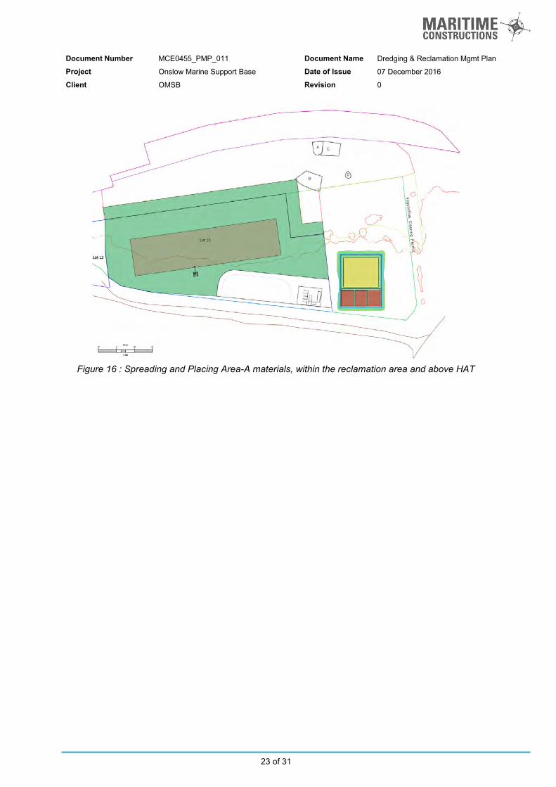
The material dredged from Area-A that was identified as the ‘high concentration TBT contamination area’ will be dewatered and stored in Geotextile bags. The material will be stored until the reclamation pad has been laid and raised above HAT (Highest Astronomical Tide). After the construction pad, and final laydown sub-base, has been raised above HAT the Area-A material may then be excavated out of the storage and containment bags and spread and placed throughout the reclaim area and capped with clean material.
Document Number MCE0455_PMP_011 Document Name Dredging & Reclamation Mgmt Plan
Project Onslow Marine Support Base Date of Issue 07 December 2016
Client OMSB Revision 0
23 of 31
Figure 16 : Spreading and Placing Area-A materials, within the reclamation area and above HAT

Document Number MCE0455_PMP_011 Document Name Dredging & Reclamation Mgmt Plan
Project Onslow Marine Support Base Date of Issue 07 December 2016
Client OMSB Revision 0
24 of 31
6.3 Clean-up Dredging After the dredging and land reclamation by the process described in the sections above, the construction team will cease dredging activities and commence the wharf construction, starting with sheet pile construction from the reclaimed construction pad. The method of construction is described in detail in the document, MCE0455_WMS_001 – Wharf Construction.
Figure 17: Site Plan during clean up dredging phase
The final dredging event will occur after the construction of the two sheet pile walls (main wall and anchor wall), installation of the tie rods and tensioning of the wall. The toe of the construction pad, which extends past the front sheet pile wall and encroaches into the berth pocket, will be dredged after the tensioning of the sheet pile wall system. This remaining toe volume, as well as the final ‘clean up’ volume will be dredged and placed to back fill the excavation between the front and anchor sheet pile walls, top up the rear laydown base, or stockpiled for relocation and use elsewhere.
Dredging of the toe of the construction pad, and the clean-up dredging will be performed by a combination of two dredging methods;
1. Dragflow dredging, suspended front a crane, and;
2. Dredging by Long Reach excavator (LRE)
Both methods are performed ‘from shore’ and are described in further detail below. After verification by hydrographic survey of the berth pocket, a final dredge plan for the clean-up dredging campaign will be made and included in the relevant SWMS.
Document Number MCE0455_PMP_011 Document Name Dredging & Reclamation Mgmt Plan
Project Onslow Marine Support Base Date of Issue 07 December 2016
Client OMSB Revision 0
25 of 31
6.3.1 Dragflow Dredge
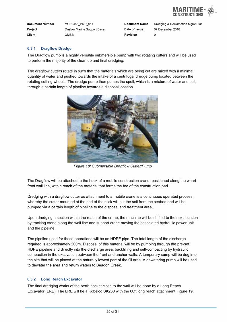
The Dragflow pump is a highly versatile submersible pump with two rotating cutters and will be used to perform the majority of the clean up and final dredging. The dragflow cutters rotate in such that the materials which are being cut are mixed with a minimal quantity of water and pushed towards the intake of a centrifugal dredge pump located between the rotating cutting wheels. The dredge pump then pumps the spoil, which is a mixture of water and soil, through a certain length of pipeline towards a disposal location.
Figure 18: Submersible Dragflow Cutter/Pump
The Dragflow will be attached to the hook of a mobile construction crane, positioned along the wharf front wall line, within reach of the material that forms the toe of the construction pad. Dredging with a dragflow cutter as attachment to a mobile crane is a continuous operated process, whereby the cutter mounted at the end of the stick will cut the soil from the seabed and will be pumped via a certain length of pipeline to the disposal and treatment area. Upon dredging a section within the reach of the crane, the machine will be shifted to the next location by tracking crane along the wall line and support crane moving the associated hydraulic power unit and the pipeline. The pipeline used for these operations will be an HDPE pipe. The total length of the discharge required is approximately 200m. Disposal of this material will be by pumping through the pre-set HDPE pipeline and directly into the discharge area, backfilling and self-compacting by hydraulic compaction in the excavation between the front and anchor walls. A temporary sump will be dug into the site that will be placed at the naturally lowest part of the fill area. A dewatering pump will be used to dewater the area and return waters to Beadon Creek. 6.3.2 Long Reach Excavator
The final dredging works of the berth pocket close to the wall will be done by a Long Reach Excavator (LRE). The LRE will be a Kobelco SK260 with the 60ft long reach attachment Figure 19.

Document Number MCE0455_PMP_011 Document Name Dredging & Reclamation Mgmt Plan
Project Onslow Marine Support Base Date of Issue 07 December 2016
Client OMSB Revision 0
26 of 31
Figure 19: Long Reach Excavator Kobelco SK260
The LRE is used for the final works as the machine has the ability to work the closest to the newly constructed wall, with the minimal risk of damage to the steel and paint system. The LRE, combined with the installed DredgePack positioning system, also provides the ability to form an accurate dredged seabed profile, which is confirmed by the final site survey. After the final survey to confirm the completion of the dredging, the remainder of the wharf and lay down area construction, as described in MCE0455_WMS_001, will continue.
Figure 20: Wharf and lay down area, after clean up dredging

Document Number MCE0455_PMP_011 Document Name Dredging & Reclamation Mgmt Plan
Project Onslow Marine Support Base Date of Issue 07 December 2016
Client OMSB Revision 0
27 of 31
6.4 Process Control The control of the dredging process is done by means of the dredging computer and the positioning system. The dredge software package we currently use on our dredges is the DREDGEPACK Dredge Operations Software. This software and hardware package is specifically designed to monitor the exact position and depth of the cutter head and keeps track of the computed “as dredged” surface.
Figure 21: Sample Screen Print of Dredgepack software
The positioning system will be Differential Global Positioning System, DGPS in combination with a tidal receiver. The output of this positioning system will be X, Y and Z co-ordinates of the vessel. With the ship’s bearing, provided by the gyro-compass, a fully determined position of the vessel is available. Cutter position is determined relative to the ship by means of an angle transducer, measuring the angle of the cutter ladder. The x, y, and z of the cutter position is calculated by the dredger computer. A sample screen print is given in Figure 21 above. With this software package and in combination with a mass-flow meter, it is possible to accurately calculate the quantity of materials moved during a shift. Regular hydrographic surveys will be performed in co-ordination with the Client to check the actual progress of the dredge, which will be used for reporting purposes. 6.5 Tolerances / Acceptance Criteria Specified depth is to be achieved at all locations. Maximum permitted tolerances to achieve design depth for the different dredge areas will be as follows: Vertical: +0m / -0.5m All dredged areas +0m / -1.0m All other areas Horizontal: -1.0m / +0.0m Toe lines adjacent to any structures (existing or proposed); -0m / +5.0m All other areas

Document Number MCE0455_PMP_011 Document Name Dredging & Reclamation Mgmt Plan
Project Onslow Marine Support Base Date of Issue 07 December 2016
Client OMSB Revision 0
28 of 31
6.6 Demobilisation Upon completion of works, demobilisation activities will begin with and include;
Dredge retrieval and transport off site (in accordance with document MCE.0455.SWMS04 Dredge Demobilisation);
Deconstruct all pipelines and transport off site (in accordance with document MCE.0455.SWMS04 Dredge Demobilisation);
The monitoring of the water quality will continue as per the water quality monitoring plan (Document MCE0450_PMP_004).

Document Number MCE0455_PMP_011 Document Name Dredging & Reclamation Mgmt Plan
Project Onslow Marine Support Base Date of Issue 07 December 2016
Client OMSB Revision 0
29 of 31
7 Resources 7.1 Assigned Equipment The following Equipment has been assigned to the works: Type of Equipment Name/Model Owner Purpose
Cutter Suction Dredge Ngurunderi MC Dredging activities
Anchor Handling Barge Carter MC Anchor Handling, Floating pipeline management
Construction Crane Manitowoc 90t Crawler MC Dragflow dredging and equipment
movements
Long Reach Excavator Kobelco 26T MC Berth Pocket Clean-up
500m CSD Pipeline Polyethylene Ø350-400mm
MC Discharge of dredged materials by CSD
100m Dragflow Pipeline Polyethylene Ø250mm MC Discharge of dredged materials by
Dragflow
Bulldozer CAT D6 3rd Party Spreading of dredged materials
Excavator CAT 320 3rd Party Bundwall maintenance and stockpiling of materials
Document Number MCE0455_PMP_011 Document Name Dredging & Reclamation Mgmt Plan
Project Onslow Marine Support Base Date of Issue 07 December 2016
Client OMSB Revision 0
30 of 31
8 Risk Management
8.1 Project Management Plans
The following additional and related management will be prepared as stand-alone documents in accordance with this Method Statement. The latest revision of each should be read in conjunction with this Construction Management Plan:
REFERENCE DOCUMENT DESCRIPTION
MCE0455_PMP_001 Construction Management Plan
MCE0455_PMP_002 Safety Management Plan
MCE0455_PMP_003 Environment Management Plan
MCE0455_PMP_004 Water Quality Monitoring Plan
MCE0455_PMP_005 Vessel Safety Management Plan (Ngurunderi)
MCE0455_PMP_006 Vessel Safety Management Plan (Carter)
MCE0455_PMP_007 Cyclone Management Plan
MCE0455_PMP_008 Employee Relations Management Plan
MCE0455_PMP_009 Site Organisation Chart
MCE0455_PMP_010 Site Induction
MCE0455_PMP_011 Dredging and Reclamation Management Plan
MCE0455_PMP_012 Communication Management Plan
MCE0455_WMS_001 Wharf Construction (Work Method Statement)
MCE0455_ITP_001 Inspection and Test Plan - Wharf Construction
MCE0455_ITP_002 Inspection and Test Plan - Dredging and Land Reclamation
MCE0455_PRM_001 Project Construction Program
MCE0455_PRA_001 Project Risk Assessment 8.2 Environmental Management Reference is made to the following documents for detailed Environmental Management, with respect to the dredging and construction activities for this project.
MCE0450_PMP_003 - Environment Management Plan
MCE0450_PMP_004 - Water Quality Monitoring Plan 8.3 Quality Control The following Inspection & Test Plans will be prepared in connection to this Work Method Statement:
REFERENCE DOCUMENT DESCRIPTION
MCE0450_ITP_001 Inspection and Test Plan - Construction
MCE0450_ITP_002 Inspection and Test Plan - Dredging and Spoil Management

Document Number MCE0455_PMP_011 Document Name Dredging & Reclamation Mgmt Plan
Project Onslow Marine Support Base Date of Issue 07 December 2016
Client OMSB Revision 0
31 of 31
8.3.1 Non-conformance
This section is applicable for all Non Conformances having direct effect on the progress and/or quality of the project works. It is also applicable for the corrective and/or preventive actions taken. The following procedures from the IMS of Maritime Constructions are applicable in these circumstances:
MC-IMSPR15C Non-conformance reporting;
MC-IMSPR16A Corrective and preventive actions register; and
MC-IMSPR16B Corrective and preventive actions.
These procedures describe the instructions for dealing with non-conformities when reported to ensure that:
non-conformities are identified, documented and reported;
the cause of the non-conformance will be investigated;
corrective and/or preventive action is taken to prevent re-occurrence; 8.4 Reporting The following reporting will be done in connection with this Work Method Statement;
IMS Form Title Responsible Interval Distribution
Daily Production Report Cutter Suction Dredge
Project Supervisor (Dredging)
Daily MC
Daily WQMP Checklist Water Quality Monitor
Daily MC
MCF-015 Daily Site Report Project Manager / Project Engineer
Daily MC
MCF-071 Weekly Toolbox Meeting Project Supervisor Weekly MC
MCF-028 Weekly Environmental Reporting
Project Supervisor Weekly MC/OMSB/DoT
Weekly (Dredging) Environmental Summary Progress and Report
Project Manager / Project Engineer
Weekly MC/OMSB/DoT
MCF-022 Incident Report Form Project Supervisor Procedural MC/ OMSB