drc travel drive control replaces: 02.04 application software · the electronic drive control is...
TRANSCRIPT
Linear Motion andAssembly Technologies ServicePneumaticsHydraulics
Electric Drives and Controls
DRC Travel Drive Control Application Software
Electronic travel drive control fortravel management of hydraulic drives
RE 95 320/06.06replaces: 02.04
FeaturesThe electronic travel drive control is an application-specifi c, adaptable software package for travel management of hydrau-lic drives. With its integrated reversing functions and hydro-static braking, it allows soft start-up, acceleration and reversing operations.
Variants DRCD and DRCE also include functions for speed limiting, diesel-engine overheating protection (via CAN), diesel-engine overspeed protection, automotive travel, load limiting control, CAN-bus interface (SAE-J 1939) and three parameter-izable travel modes which can be selected by the driver.
The integrated, adjustable inch function enables infi nite limiting of the pump control.
Variants A, B and C:
– Travel drives with simple pump control in combination with fi xed displacement motors
Variants D and E:
– Complex travel drives with pump and motor control
The DRC travel drive control is designed foroperation with Rexroth pumps A4VG and A10VG with electric control (proportional solenoid).
The software can be parameterized by the user.
Diagnostics and parameterization are possible with the BO-DEM PC software.
The control offers diagnostic capabilities via the CAN bus.
Contents
Ordering code 2
Variant overview 3
Variants DRCA through DRCC 4Functional description 4Parameterization and diagnostics 6DRCA connection diagram 7DRCB connection diagram 8DRCC connection diagram 9Required components 10
Variants DRCD and DRCE 11Functional description 12Parameterization and diagnostics 15DRCD connection diagrams 16DRCE connection diagrams 18Required components 20
Safety instructions 20
Technical data sheet
2/20 Bosch Rexroth AG DRC Travel Drive Control RE 95 320/06.06
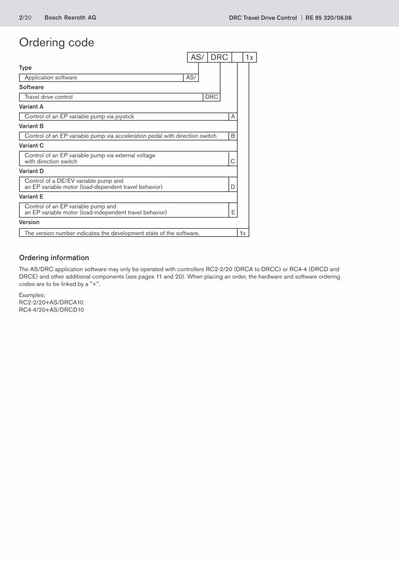
Ordering informationThe AS/DRC application software may only be operated with controllers RC2-2/20 (DRCA to DRCC) or RC4-4 (DRCD and DRCE) and other additional components (see pages 11 and 20). When placing an order, the hardware and software ordering codes are to be linked by a "+".
Examples: RC2-2/20+AS/DRCA10RC4-4/20+AS/DRCD10
Ordering code AS/ DRC 1xType
Application software AS/
Software
Travel drive control DRC
Variant A
Control of an EP variable pump via joystick A
Variant B
Control of an EP variable pump via acceleration pedal with direction switch B
Variant C
Control of an EP variable pump via external voltage with direction switch C
Variant D
Control of a DE/EV variable pump and an EP variable motor (load-dependent travel behavior) D
Variant E
Control of an EP variable pump and an EP variable motor (load-independent travel behavior) E
Version
The version number indicates the development state of the software. 1x
Bosch Rexroth AGRE 95 320/06.06 DRC Travel Drive Control 3/20
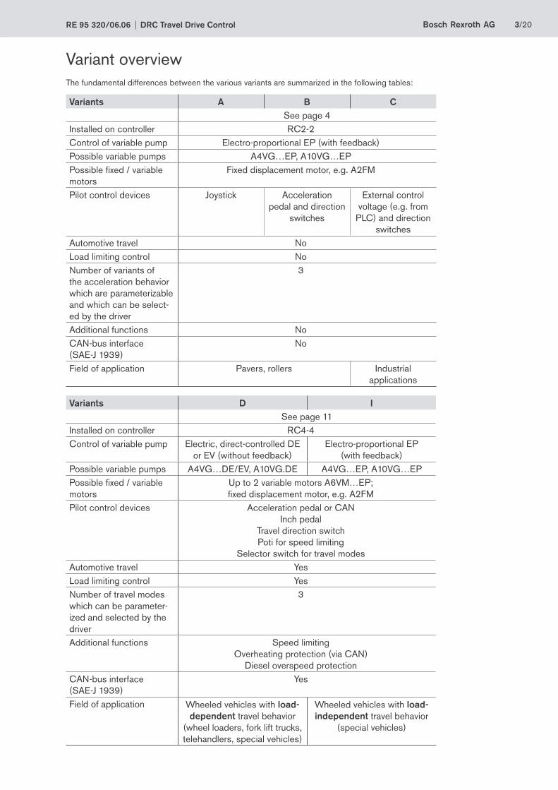
Variant overviewThe fundamental differences between the various variants are summarized in the following tables:
Variants A B CSee page 4
Installed on controller RC2-2Control of variable pump Electro-proportional EP (with feedback)Possible variable pumps A4VG…EP, A10VG…EPPossible fi xed / variable motors
Fixed displacement motor, e.g. A2FM
Pilot control devices Joystick Acceleration pedal and direction
switches
External control voltage (e.g. from
PLC) and direction switches
Automotive travel NoLoad limiting control NoNumber of variants of the acceleration behavior which are parameterizable and which can be select-ed by the driver
3
Additional functions NoCAN-bus interface (SAE-J 1939)
No
Field of application Pavers, rollers Industrial applications
Variants D ISee page 11
Installed on controller RC4-4Control of variable pump Electric, direct-controlled DE
or EV (without feedback)Electro-proportional EP
(with feedback)Possible variable pumps A4VG…DE/EV, A10VG.DE A4VG…EP, A10VG…EPPossible fi xed / variable motors
Up to 2 variable motors A6VM…EP; fi xed displacement motor, e.g. A2FM
Pilot control devices Acceleration pedal or CAN Inch pedal Travel direction switch Poti for speed limiting Selector switch for travel modes
Automotive travel YesLoad limiting control YesNumber of travel modes which can be parameter-ized and selected by the driver
3
Additional functions Speed limiting Overheating protection (via CAN) Diesel overspeed protection
CAN-bus interface (SAE-J 1939)
Yes
Field of application Wheeled vehicles with load-dependent travel behavior
(wheel loaders, fork lift trucks, telehandlers, special vehicles)
Wheeled vehicles with load-independent travel behavior
(special vehicles)

4/20 Bosch Rexroth AG DRC Travel Drive Control RE 95 320/06.06
Variants DRCA, DRCB and DRCCThe electronic drive control is designed to actuate a variable pump in a closed hydraulic circuit.
Control is based on the following hydraulic concept:
• An A4VG or A10VG variable pump with electro-proportional EP control combined with one or more A2FM, A2FE, A4FM or A10FM fi xed displacement motors.
The following diesel engine confi guration can be used:
• Diesel engine with or without CAN-bus interfaceThe travel drive control receives the actual speed value via a speed sensor.
Functional descriptionThe software is used for the realization of easily reversible hydraulic drives. Figure 1 shows a typical confi guration for the travel drive control.
Setpoint specifi cationThe desired vehicle speed and travel direction are specifi ed via the setpoint specifi cation. This can be performed in three different ways:
Figure 1: Typical configuration for the DRC travel drive control, variants A-C (DRCA to DRCC)
• Variant A: Joystick
If the drive is controlled via a joystick, the setpoint and travel direction are specifi ed via this lever. The potentiometer of the joystick is monitored for wire break and short circuit.
• Variant B: Acceleration pedal
If the drive is controlled via an acceleration pedal, two direction switches (for forwards/backwards travel) must also be connected. The setpoint is specifi ed via the pedal, the travel direction via the direction switches. The potentiometer connected to the acceleration pedal is monitored for wire break and short circuit.
• Variant C: External control voltage
If the drive is controlled via an external voltage, for example via a PLC, two direction switches (for forwards/backwards travel direction ) can also be connected. The setpoint is specifi ed via the external control voltage, the travel direction via a control signal or the direction switches.
Where setpoint specifi cation occurs via an external control voltage, no monitoring is carried out by the travel drive control. Undefi ned states at the inputs can cause the drive to start unintentionally.
Safety monitoring must be guaranteed by the connected signal source (e.g. PLC).
Powersupply Ignition lock
RC2-2controller with DRC software
Diagnosticssocket
CAN-bus interface
Speed limiting
Start release signalfor starter
HG joystick valve
Two optionaldirection switches
Two optional switches for acceleration
behavior
Optionalspeed sensor
Engine Variable pumpA4VG...EP orA10VG...EP
Fixed displacement motorA2FM orA2FE orA4FM orA10FM
BODEM PC softwareRS232
Bosch Rexroth AGRE 95 320/06.06 DRC Travel Drive Control 5/20
Inch functionA second potentiometer can be connected for infi nitely variable setpoint limitation.
For variants A and B, the inching potentiometer is monitored for wire break and short circuit.
For variant C, the values at the input for the inching potentiom-eter are specifi ed by an external control voltage. In this case safety must be guaranteed by the connected signal source.
Travel behaviorTravel behavior is controlled by three variables.
• The setpoint is specifi ed via the joystick, the acceleration pedal or the external control voltage (depending on the vari-ant).
• The control of the PWM output for the specifi ed setpoint is defi ned in the travel behavior characteristic.
• The acceleration behavior selected by the position of the time ramp switch determines how quickly the control at the PWM output changes.
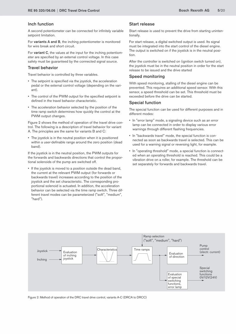
Figure 2 shows the method of operation of the travel drive con-trol. The following is a description of travel behavior for variant A. The principles are the same for variants B and C:
• The joystick is in the neutral position when it is positioned within a user-defi nable range around the zero position (dead band).
If the joystick is in the neutral position, the PWM outputs for the forwards and backwards directions that control the propor-tional solenoids of the pump are switched off.
• If the joystick is moved to a position outside the dead band, the current at the relevant PWM output (for forwards or backwards travel) increases according to the position of the joystick and the set characteristic. The corresponding pro-portional solenoid is actuated. In addition, the acceleration behavior can be selected via the time ramp switch. Three dif-ferent travel modes can be parameterized ("soft", "medium", "hard").
Start releaseStart release is used to prevent the drive from starting uninten-tionally.
For start release, a digital switched output is used. Its signal must be integrated into the start control of the diesel engine. The output is switched on if the joystick is in the neutral posi-tion.
After the controller is switched on (ignition switch turned on), the joystick must be in the neutral position in order for the start release to be issued and the drive started
Speed monitoringWith speed monitoring, stalling of the diesel engine can be prevented. This requires an additional speed sensor. With this sensor, a speed threshold can be set. This threshold must be exceeded before the drive can be started.
Special functionThe special function can be used for different purposes and in different modes:
• In "error lamp" mode, a signaling device such as an error lamp can be connected in order to display various error warnings through different fl ashing frequencies.
• In "backwards travel" mode, the special function is con-nected as soon as backwards travel is selected. This can be used for a warning signal or reversing light, for example.
• In "operating threshold" mode, a special function is connect-ed when an operating threshold is reached. This could be a vibration drive on a roller, for example. The threshold can be set separately for forwards and backwards travel.
Figure 2: Method of operation of the DRC travel drive control, variants A-C (DRCA to DRCC)
Joystick
Inching
Evaluationof inchingjoystick
Characteristics Time ramps
Ramp selection("soft", "medium", "hard")
Evaluationof direction
Evaluationof special switching functions,error lamp
Pumpcontrol(electr. current)
Specialswitching functions0V/12V(24V)
6/20 Bosch Rexroth AG DRC Travel Drive Control RE 95 320/06.06
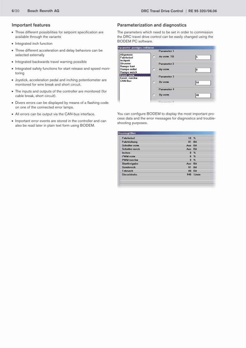
Parameterization and diagnosticsThe parameters which need to be set in order to commission the DRC travel drive control can be easily changed using the BODEM PC software.
You can confi gure BODEM to display the most important pro-cess data and the error messages for diagnostics and trouble-shooting purposes.
Important features• Three different possibilities for setpoint specifi cation are
available through the variants
• Integrated inch function
• Three different acceleration and delay behaviors can be selected externally
• Integrated backwards travel warning possible
• Integrated safety functions for start release and speed moni-toring
• Joystick, acceleration pedal and inching potentiometer are monitored for wire break and short circuit.
• The inputs and outputs of the controller are monitored (for cable break, short circuit).
• Divers errors can be displayed by means of a fl ashing code on one of the connected error lamps.
• All errors can be output via the CAN-bus interface.
• Important error events are stored in the controller and can also be read later in plain text form using BODEM.

Bosch Rexroth AGRE 95 320/06.06 DRC Travel Drive Control 7/20
Figure 3: Inputs and outputs on controller for DRC, variant A (DRCA)
DRCA connection diagram
Ignition lock with starter non-repeat unit
Supply voltage of the electronics
Powerinput
Supply of the power outputs
Pro
port
iona
lou
tput
sS
witc
hed
outp
uts
Freq
uenc
y in
puts
Sen
sor
supp
ly v
olta
geVo
ltage
inpu
tsC
urre
nt in
puts
Sw
itche
d in
puts
GroundSpeed sensor 1
Joystickpotentiometer 1(1 to 5k)
Inchingpotentiometer 2(1 to 5k)
Pump forwards
Pump backwards
Start release
Special function
Travel behavior 1
Travel behavior 2
Diagnostics plugfor BODEM
CAN bus 4)
Ground connection for case
Reserved
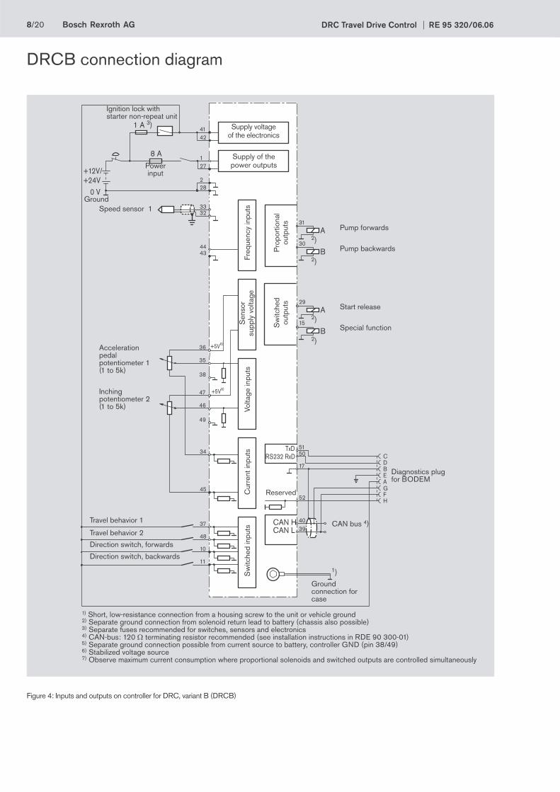
1) Short, low-resistance connection from a housing screw to the unit or vehicle ground2) Separate ground connection from solenoid return lead to battery (chassis also possible)3) Separate fuses recommended for switches, sensors and electronics4) CAN-bus: 120 Ω terminating resistor recommended (see installation instructions in RDE 90 300-01)5) Separate ground connection possible from current source to battery, controller GND (pin 38/49)6) Stabilized voltage source7) Observe maximum current consumption where proportional solenoids and switched outputs are controlled simultaneously
8/20 Bosch Rexroth AG DRC Travel Drive Control RE 95 320/06.06
Figure 4: Inputs and outputs on controller for DRC, variant B (DRCB)
DRCB connection diagram
Direction switch, forwards
Direction switch, backwards
Ignition lock with starter non-repeat unit
Supply voltage of the electronics
Powerinput
Supply of the power outputs
Pro
port
iona
lou
tput
sS
witc
hed
outp
uts
Freq
uenc
y in
puts
Sen
sor
supp
ly v
olta
geVo
ltage
inpu
tsC
urre
nt in
puts
Sw
itche
d in
puts
GroundSpeed sensor 1
Acceleration pedalpotentiometer 1(1 to 5k)
Inchingpotentiometer 2(1 to 5k)
Pump forwards
Pump backwards
Start release
Special function
Travel behavior 1
Travel behavior 2
Diagnostics plugfor BODEM
CAN bus 4)
Ground connection for case
Reserved
1) Short, low-resistance connection from a housing screw to the unit or vehicle ground2) Separate ground connection from solenoid return lead to battery (chassis also possible)3) Separate fuses recommended for switches, sensors and electronics4) CAN-bus: 120 Ω terminating resistor recommended (see installation instructions in RDE 90 300-01)5) Separate ground connection possible from current source to battery, controller GND (pin 38/49)6) Stabilized voltage source7) Observe maximum current consumption where proportional solenoids and switched outputs are controlled simultaneously

Bosch Rexroth AGRE 95 320/06.06 DRC Travel Drive Control 9/20
Figure 5: Inputs and outputs on controller for DRC, variant C (DRCC)
DRCC connection diagram
Ext
. set
poin
t sp
ecifi
catio
nE
xt. s
etpo
int
spec
ifi ca
tion
Direction switch, forwards
Direction switch, backwards
Ignition lock with starter non-repeat unit
Supply voltage of the electronics
Powerinput
Supply of the power outputs
Pro
port
iona
lou
tput
sS
witc
hed
outp
uts
Freq
uenc
y in
puts
Sen
sor s
uppl
y vo
ltage
Volta
ge in
puts
Cur
rent
inpu
tsS
witc
hed
inpu
ts
GroundSpeed sensor 1
Pump forwards
Pump backwards
Start release
Special function
Travel behavior 1
Travel behavior 2
Diagnostics plugfor BODEM
CAN bus 4)
Ground connection for case
Reserved
1) Short, low-resistance connection from a housing screw to the unit or vehicle ground2) Separate ground connection from solenoid return lead to battery (chassis also possible)3) Separate fuses recommended for switches, sensors and electronics4) CAN-bus: 120 Ω terminating resistor recommended (see installation instructions in RDE 90 300-01)5) Separate ground connection possible from current source to battery, controller GND (pin 38/49)6) Stabilized voltage source7) Observe maximum current consumption where proportional solenoids and switched outputs are controlled simultaneously
10/20 Bosch Rexroth AG DRC Travel Drive Control RE 95 320/06.06
Required componentsThe following electronic components are required:
• RC2-2/20 controller with 52-pin mating connector (RE 95200)
• Software AS/DRCA, AS/DRCB or AS/DRCC
• HG104 joystick (RE 95041)
• Optional: IDR speed sensor (RE 95130) with mating con-nector
• Optional: acceleration and inch pedals
• Optional: time-ramp switch for the acceleration behavior
• Optional: direction switch
The following hydraulic components are required:
• Variable pump with electro-proportional control A4VG…EP (RE 92003) orA10VG…EP (RE 92750)
• Fixed displacement motorA2FM (RE 91001) orA2FE (RE 91008) orA4FM (RE 91120) orA10FM (RE 91172)
The following items are required for commissioning and ser-vice:
• Diagnostics socket (RE 95085)
• BODEM PC software with BODEM connecting cable (RE 95085)
Bosch Rexroth AGRE 95 320/06.06 DRC Travel Drive Control 11/20
Variants DRCD and DRCEHydraulic systemThe electronic travel drive control is designed to actuate a variable pump in a closed hydraulic circuit with electric, direct-controlled DE / EV control (DRCD) or electric, proportional EP control (DRCE) and a variable motor with electric, proportional EP control.
The following Rexroth hydraulic pumps are supported:
DRCD:
• A4VG.DE, A4VG.EV (see catalog RE 92003)
• A10VG.DE (see catalog RE 92750)
DRCE:
• A4VG.EP (see catalog RE 92003)
• A10VG.EP (see catalog RE 92750)
In combination with the variable pump, multiple fi xed or up to two variable motors can be used.
The following Rexroth fi xed displacement motors are sup-ported:
• A2FM (see catalog RE 91001)
• A2FE (see catalog RE 91008)
• A4FM (see catalog RE 91120)
• A10FM (see catalog RE 91172)
The following Rexroth variable motor is supported:
• A6VM.EP (see catalog RE 91 604)
The electronic travel drive control can be used with a diesel engine with or without a CAN bus interface.
InterfacesComprehensive information on interfaces and technical data for the RC4-4 controller can be found in the catalog entitled "Controller RC" (RE 95 200). The most important interfaces for the DRCD and DRCE electronic travel drive control are:
• Analog input signals (from potentiometers or angle sensors)
Analog voltages in the range from 0 - 5 V are received as input signals by the DRCD and DRCE.
• Digital input signals (from switches)
DRCD and DRCE receive digital input signals from the travel direction switch, from the switch for determining the travel mode, from the seat switch and, if applicable, from the switch contacts on the acceleration and inch pedals.
The "teach function" input can be used to activate calibration of the potentiometers and the plotting of the teach curve without BODEM.
• Frequency inputs (from the speed sensor)
The DRCD and DRCE can receive frequency signals from speed sensors for the purpose of monitoring the speed of the diesel engine and of the hydraulic motor.
• Proportional outputs (PWM currents)
The DRCD and DRCE supply regulated pulse-width modulated currents for direct control of proportional solenoids. The dither frequency optimizes these outputs for accuracy and minimum hysteresis for the electrical control of pumps and hydraulic motors.
• Switched outputs
The DRCD and DRCE supply digital output signals for direct control of on/off solenoids. These outputs control the directional valve of the pump for travel direction pre-selection.
The DRCD and DRCE supply a digital output signal for connecting an error lamp.
• CAN-bus interface
The CAN-bus interface CAN1 is available for transmitting the speed and the temperature of the diesel engine. In addition, the position of the acceleration pedal can be determined by the diesel engine. Diagnostic messages can be transmitted on CAN2 by the RC controller.
• Diagnostics interface
To communicate with the parameterization and diagnostic tools, the tool in question must be connected to the controller via a special diagnostics socket.This diagnostics socket needs to be part of the cable harness. This enables the connection of a laptop with the BODEM PC software (RE 95 085).BODEM can be used for communicating with a variety of controllers available in the Rexroth line.

12/20 Bosch Rexroth AG DRC Travel Drive Control RE 95 320/06.06
Functional descriptionAutomotive travelThe hydrostatic drive with travel drive control facilitates com-fortable driving, such as that experienced in an automobile. The variable pump is controlled by the defl ection of the acceleration pedal. The variable motor follows after the pump is fully swiv-eled out.
DRCDThe travel behavior of the DRCD drive control is load de-pendent, as with all cars or trucks. With increasing load, the vehicle slows or becomes sluggish. Examples here include be-ginning to climb after traveling on a fl at stretch or the difference between a loaded and an empty vehicle. The load dependence has the advantage that the driver has a better feel for the driv-ing status and conditions.
DRCEThe travel behavior of the DRCE drive control is load indepen-dent if suffi cient drive power is present. It is therefore particu-larly well suited for applications in which it is important that fi xed speeds be maintained.
Inch functionA potentiometer can be used to infi nitely limit the pump and, therefore, the fl ow from the pump. Thus, the vehicle speed can be decoupled from the diesel engine speed.
As a result, the vehicle can be driven slowly while at the same time maintaining maximum diesel speed to provide maximum fl ow for the working hydraulics.
The inch function can be activated or deactivated via param-eters.
Powersupply
Ignition lock
RC4-4 controllerwith DRCD and DRCE software
BODEM PC software
RS
232
Dia
gnos
tics
sock
et
Spe
ed li
miti
ng
Acc
el. p
edal
Tem
pera
ture
of d
iese
l eng
ine
via
CA
N
Die
sel e
ngin
e sp
eed
via
spee
d se
nsor
or v
ia
CA
N
Engine Variable pump A4VG...DE/EV/EPor A10VG...DE/EP
Variable motor A6VM...EP or fi xed displacement motor A2FM or A2FE, or A4FMor A10FM
Spe
ed s
enso
r
Inch
ped
al
Spe
ed li
miti
ng
Inch
ped
al
Trav
el d
irect
ion
Teac
h fu
nctio
n
Spe
cial
func
tion
Sea
t sw
itch
Spe
cial
func
tion
Figure 6: Typical configuration for the DRC travel drive control, variants D-E (DRCD and DRCE)

Bosch Rexroth AGRE 95 320/06.06 DRC Travel Drive Control 13/20
Evaluation
Direction switch
Control of variable pump
Accel. pedal
Inch pedal
Control of variable motors
Time rampsTravel behavior
Pre-position Time ramps
Diesel engine speed
Diesel temperature
Output speed
• Load limiting control• Overheating pro-
tection• Diesel protection• Speed limiting
Travel behavior("soft", "medium", "hard")
Evaluation
Teach curve
Inch function
Figure 7: Method of operation of the DRC travel drive control, variants D-E (DRCD and DRCE)
Travel behaviorTravel behavior is controlled by the following variables.
• The travel mode ("soft", "medium", "hard") is defi ned with one switch and two digital inputs. This determines, among other properties, how quickly the control of the proportional outputs is changed.
• The setpoint value for the pump and motor is specifi ed by the acceleration pedal and the teach curve. The direction is specifi ed by the direction switch.
• The control of the variable pump for the specifi ed diesel-engine-speed setpoint value is defi ned in the travel behavior characteristic.
A separate characteristic with the corresponding ramps can be parameterized for each travel mode ("soft", "medium", "hard").
• The output speed at the hydraulic motor and the acceleration pedal defi ne the behavior of the variable motors.
If the acceleration pedal is pressed:
• If a fi xed displacement motor is connected (only the variable pump is controlled), the current value of the pump control increases.
The current value increases with increasing defl ection of the acceleration pedal. The pump swivels out further and the vehicle speed increases.
The fi xed displacement motor reaches its maximum speed at maximum pump fl ow.
• If a variable motor is connected (both variable pump as well as variable motors are controlled):
With increasing defl ection of the acceleration pedal, the swivel angle of the pump is initially increased. If the pump is completely swiveled out, the swivel angle of the variable motor is also reduced and, as a result, so too is the displacement. The variable motor is guided by the measured output speed (hydraulic-motor speed-guided behavior). The output speed continues to increase.
With the acceleration pedal fully pushed down, the pump control is at a maximum and the motor is swiveled back to a minimum displacement Vg min determined by the hydraulic travel drive control. The variable motor has reached the maximum output speed.
The travel behavior is defi ned via two switched inputs. The selected travel mode determines:
• The characteristic for the travel behavior
• The characteristic for the pre-position
• The reaction behavior during reversing
14/20 Bosch Rexroth AG DRC Travel Drive Control RE 95 320/06.06
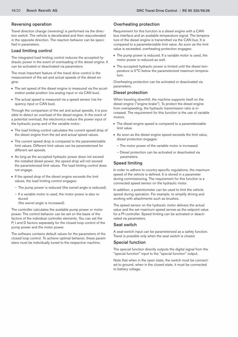
Reversing operationTravel direction change (reversing) is performed via the direc-tion switch. The vehicle is decelerated and then reaccelerated in the opposite direction. The reaction behavior can be speci-fi ed in parameters.
Load limiting controlThe integrated load limiting control reduces the accepted hy-draulic power in the event of overloading of the diesel engine. It can be activated or deactivated via parameters.
The most important feature of the travel drive control is the measurement of the set and actual speeds of the diesel en-gine.
• The set speed of the diesel engine is measured via the accel-eration pedal position (via analog input or via CAN bus).
• The actual speed is measured via a speed sensor (via fre-quency input or CAN bus).
Through the comparison of the set and actual speeds, it is pos-sible to detect an overload of the diesel engine. In the event of a potential overload, the electronics reduce the power input of the hydraulic pump and of the variable motor:
• The load limiting control calculates the current speed drop of the diesel engine from the set and actual speed values.
• The current speed drop is compared to the parameterizable limit values. Different limit values can be parameterized for different set speeds.
• As long as the accepted hydraulic power does not exceed the installed diesel power, the speed drop will not exceed the parameterized limit values. The load limiting control does not engage.
• If the speed drop of the diesel engine exceeds the limit values, the load limiting control engages:
– The pump power is reduced (the swivel angle is reduced).
– If a variable motor is used, the motor power is also re-duced (the swivel angle is increased).
The controller calculates the available pump power or motor power. The control behavior can be set on the basis of the factors of the individual controller elements. You can set the P, I and D factors separately for the closed loop control of the pump power and the motor power.
The software contains default values for the parameters of the closed loop control. To achieve optimal behavior, these param-eters must be individually tuned to the respective machine.
Overheating protection Requirement for this function is a diesel engine with a CAN-bus interface and an available temperature signal. The tempera-ture of the diesel engine is transmitted via the CAN bus. It is compared to a parameterizable limit value. As soon as the limit value is exceeded, overheating protection engages:
• The pump power is reduced. If a variable motor is used, the motor power is reduced as well.
• The accepted hydraulic power is limited until the diesel tem-perature is 5 °C below the parameterized maximum tempera-ture.
Overheating protection can be activated or deactivated via parameters.
Diesel protection When traveling downhill, the machine supports itself on the diesel engine ("engine brake"). To protect the diesel engine from overspeeding, the hydraulic transmission ratio is in-creased. The requirement for this function is the use of variable motors.
• The diesel engine speed is compared to a parameterizable limit value.
• As soon as the diesel engine speed exceeds the limit value, diesel protection engages:
– The motor power of the variable motor is increased.
– Diesel protection can be activated or deactivated via parameters.
Speed limiting In order to adhere to country-specifi c regulations, the maximum speed of the vehicle is defi ned. It is stored in a parameter during commissioning. The requirement for this function is a connected speed sensor on the hydraulic motor.
In addition, a potentiometer can be used to limit the vehicle speed during operation. For example, to simplify driving and working with attachments such as brushes.
The speed sensor on the hydraulic motor delivers the actual value and the set maximum speed serves as the setpoint value for a PI controller. Speed limiting can be activated or deacti-vated via parameters.
Seat switch A seat-switch input can be parameterized as a safety function. Travel is possible only when the seat switch is closed.
Special function The special function directly outputs the digital signal from the "special function" input to the "special function" output.
Note that when in the open state, the switch must be connect-ed to ground; when in the closed state, it must be connected to battery voltage.

Bosch Rexroth AGRE 95 320/06.06 DRC Travel Drive Control 15/20
Important features• Automotive travel
• Selectable travel modes
• Integrated load limiting control
• Reversing operation
• Integrated inch function
• Three different acceleration and delay behaviors can be selected externally
• Parameterizable speed limiting
• Integrated overheating protection of the diesel engine
• Integrated safety functions for start release
• Analog inputs and proportional outputs are monitored for wire break and short circuit.
• Divers errors can be displayed by means of a fl ashing code on one of the connected error lamps.
• All errors can be output via the CAN-bus interface.
• Important error events are stored in the controller and can also be read later in plain text form using BODEM.
Parameterization and diagnosticsThe parameters which need to be set in order to commission the DRC travel drive control can be easily changed using the BODEM PC software.
You can confi gure BODEM to display the most important pro-cess data and the error messages for diagnostics and trouble-shooting purposes.
16/20 Bosch Rexroth AG DRC Travel Drive Control RE 95 320/06.06
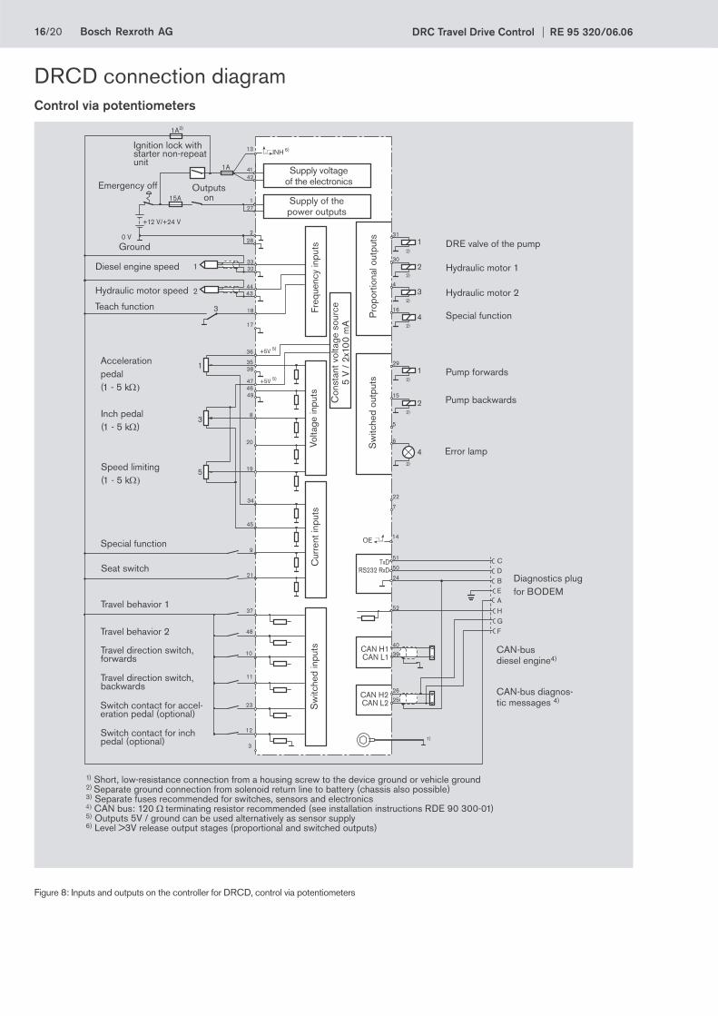
Figure 8: Inputs and outputs on the controller for DRCD, control via potentiometers
DRCD connection diagramControl via potentiometers
22
7
51
50
24
40
39
26
25
TxDRS232 RxD
CAN H1CAN L1
CAN H2CAN L2
CDBEA
1
2
3
1
3
5
15A
1A3)
27
4241
2
1
28
+12 V/+24 V
0 V
1A
37
48
10
11
23
14
12
3332
4443
18
17
H52
GF
1
2
3
31
30
4
16
1
4
4
29
15
5
6
OE
35
36
38
47
49
8
20
19
+5V 5)
+5V 5)
45
34
9
21
1)
2)
22)
2)
2)
2)
2)
2)
3
INH13Ignition lock with starter non-repeat unit
Emergency off Outputs on
Ground
Diesel engine speed
Hydraulic motor speed
Seat switch
Acceleration pedal(1 - 5 kΩ)
Inch pedal(1 - 5 kΩ)
Speed limiting (1 - 5 kΩ)
Special function
Teach function
Supply voltage of the electronics
Supply of the power outputs
Pro
port
iona
l out
puts
Sw
itche
d ou
tput
s
Freq
uenc
y in
puts
Volta
ge in
puts
Cur
rent
inpu
tsS
witc
hed
inpu
ts
Con
stan
t vol
tage
sou
rce
5 V
/ 2
x100
mA
CAN-busdiesel engine4)
Diagnostics plugfor BODEM
Pump forwards
Pump backwards
Special function
Error lamp
Hydraulic motor 1
DRE valve of the pump
Hydraulic motor 2
1) Short, low-resistance connection from a housing screw to the device ground or vehicle ground2) Separate ground connection from solenoid return line to battery (chassis also possible)3) Separate fuses recommended for switches, sensors and electronics4) CAN bus: 120 Ω terminating resistor recommended (see installation instructions RDE 90 300-01)5) Outputs 5V / ground can be used alternatively as sensor supply6) Level >3V release output stages (proportional and switched outputs)
Travel behavior 1
Travel behavior 2
Travel direction switch, forwards
Travel direction switch, backwards
Switch contact for accel-eration pedal (optional)
Switch contact for inch pedal (optional)
CAN-bus diagnos-tic messages 4)

Bosch Rexroth AGRE 95 320/06.06 DRC Travel Drive Control 17/20
Figure 9: Inputs and outputs on the controller for DRCD, control via angle sensors
22
7
51
50
24
40
39
26
25
TxDRS232 RxD
CAN H1CAN L1
CAN H2CAN L2
CDBEA
1
2
3
15A
1A3)
27
4241
2
1
28
+12 V/+24 V
0 V
1A
37
48
10
11
23
3
13
14
12
3332
4443
18
17
H52
GF
1
2
3
31
30
4
16
1
2
4
4
29
15
5
6
OE
135 36
38
474649
8
20
19
+5V 5)
+5V 5)
45
34
9
21
1)
2)
2)
2)
2)
2)
2)
2)
5
4
6
15
5
4
6
WS 1
WS 1
+
+–
–
INH
Ignition lock with starter non-repeat unit
Emergency off Outputs on
Ground
Diesel engine speed
Hydraulic motor speed
Seat switch
Special function
Teach function
Supply voltage of the electronics
Supply of the power outputs
Pro
port
iona
l out
puts
Sw
itche
d ou
tput
s
Freq
uenc
y in
puts
Volta
ge in
puts
Cur
rent
inpu
tsS
witc
hed
inpu
ts
Con
stan
t vol
tage
sou
rce
5 V
/ 2
x100
mA
CAN-busdiesel engine 4)
Diagnostics plugfor BODEM
Pump forwards
Pump backwards
Special function
Error lamp
Hydraulic motor 1
DRE valve of the pump
Hydraulic motor 2
1) Short, low-resistance connection from a housing screw to the device ground or vehicle ground2) Separate ground connection from solenoid return line to battery (chassis also possible)3) Separate fuses recommended for switches, sensors and electronics4) CAN bus: 120 Ω terminating resistor recommended (see installation instructions RDE 90 300-01)5) Outputs 5V / ground can be used alternatively as sensor supply6) Level >3V release output stages (proportional and switched outputs)
Travel behavior 1
Travel behavior 2
Travel direction switch, forwards
Travel direction switch, backwards
Accel. pedal
Inch pedal
Speed limiting (1 - 5 kΩ)
CAN-bus diagnos-tic messages 4)
DRCD connection diagramControl via angle sensors
18/20 Bosch Rexroth AG DRC Travel Drive Control RE 95 320/06.06
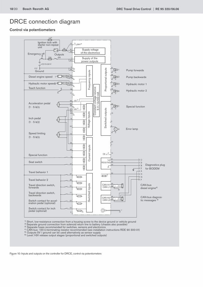
Figure 10: Inputs and outputs on the controller for DRCE, control via potentiometers
22
7
51
50
24
40
39
26
25
TxDRS232 RxD
CAN H1CAN L1
CAN H2CAN L2
CDBEA
1
2
3
1
3
5
15A
1A3)
27
4241
2
1
28
+12 V/+24 V
0 V
1A
37
48
10
11
23
14
12
3332
4443
18
17
H52
GF
1
2
3
31
30
4
16
1
4
4
29
15
5
6
OE
35
36
38
47
49
8
20
19
+5V 5)
+5V 5)
45
34
9
21
1)
2)
2)
2)
2)
2)
2)
3
INH13Ignition lock with starter non-repeat unit
Emergency off Outputs on
Ground
Diesel engine speed
Hydraulic motor speed
Seat switch
Acceleration pedal(1 - 5 kΩ)
Inch pedal (1 - 5 kΩ)
Speed limiting (1 - 5 kΩ)
Special function
Teach function
Supply voltage of the electronics
Supply of the power outputs
Pro
port
iona
l out
puts
Sw
itche
d ou
tput
s
Freq
uenc
y in
puts
Volta
ge in
puts
Cur
rent
inpu
tsS
witc
hed
inpu
ts
Con
stan
t vol
tage
sou
rce
5 V
/ 2
x100
mA
CAN-busdiesel engine4)
Diagnostics plugfor BODEM
Special function
Hydraulic motor 2
Error lamp
Pump backwards
Pump forwards
Hydraulic motor 1
1) Short, low-resistance connection from a housing screw to the device ground or vehicle ground2) Separate ground connection from solenoid return line to battery (chassis also possible)3) Separate fuses recommended for switches, sensors and electronics4) CAN bus: 120 Ω terminating resistor recommended (see installation instructions RDE 90 300-01)5) Outputs 5V / ground can be used alternatively as sensor supply6) Level >3V release output stages (proportional and switched outputs)
Travel behavior 1
Travel behavior 2
Travel direction switch, forwards
Travel direction switch, backwards
Switch contact for accel-eration pedal (optional)
Switch contact for inch pedal (optional)
CAN-bus diagnos-tic messages 4)
DRCE connection diagramControl via potentiometers
Bosch Rexroth AGRE 95 320/06.06 DRC Travel Drive Control 19/20
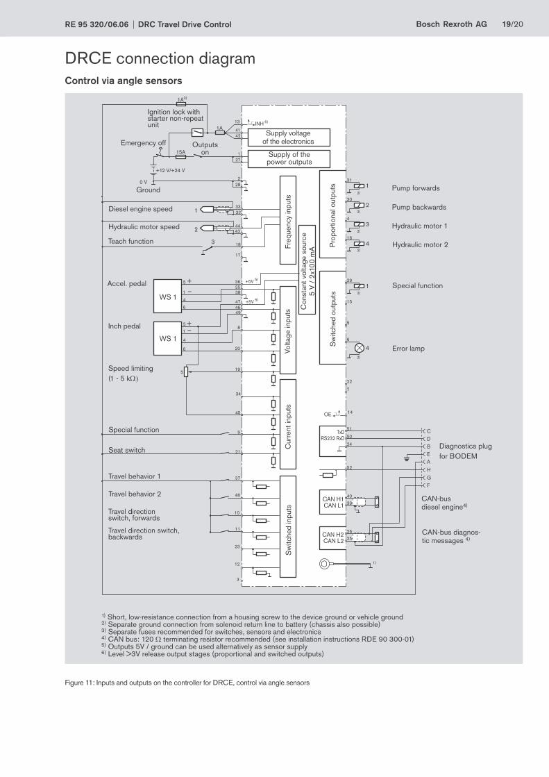
Figure 11: Inputs and outputs on the controller for DRCE, control via angle sensors
22
7
51
50
24
40
39
26
25
TxDRS232 RxD
CAN H1CAN L1
CAN H2CAN L2
CDBEA
1
2
3
15A
1A3)
27
4241
2
1
28
+12 V/+24 V
0 V
1A
37
48
10
11
23
3
13
14
12
3332
4443
18
17
H52
GF
1
2
3
31
30
4
16
1
4
4
29
15
5
6
OE
135 36
38
474649
8
20
19
+5V 5)
+5V 5)
45
34
9
21
1)
2)
2)
2)
2)
2)
2)
5
4
6
15
5
4
6
WS 1
WS 1
+
+–
–
INH
Ignition lock with starter non-repeat unit
Emergency off Outputs on
Ground
Diesel engine speed
Hydraulic motor speed
Seat switch
Special function
Teach function
Supply voltage of the electronics
Supply of the power outputs
Pro
port
iona
l out
puts
Sw
itche
d ou
tput
s
Freq
uenc
y in
puts
Volta
ge in
puts
Cur
rent
inpu
tsS
witc
hed
inpu
ts
Con
stan
t vol
tage
sou
rce
5 V
/ 2
x100
mA
CAN-busdiesel engine4)
Diagnostics plugfor BODEM
Special function
Hydraulic motor 2
Error lamp
Pump backwards
Pump forwards
Hydraulic motor 1
1) Short, low-resistance connection from a housing screw to the device ground or vehicle ground2) Separate ground connection from solenoid return line to battery (chassis also possible)3) Separate fuses recommended for switches, sensors and electronics4) CAN bus: 120 Ω terminating resistor recommended (see installation instructions RDE 90 300-01)5) Outputs 5V / ground can be used alternatively as sensor supply6) Level >3V release output stages (proportional and switched outputs)
Travel behavior 1
Travel behavior 2
Travel direction switch, forwards
Travel direction switch, backwards
Accel. pedal
Inch pedal
Speed limiting (1 - 5 kΩ)
CAN-bus diagnos-tic messages 4)
DRCE connection diagramControl via angle sensors

20/20 Bosch Rexroth AG DRC Travel Drive Control RE 95 320/06.06
© This document, as well as the data, specifi cations and other information set forth in it, are the exclusive property of Bosch Rexroth AG. It may not be reproduced or given to third parties without its consent.The data specifi ed above only serve to describe the product. No statements concerning a certain condition or suitability for a certain application can be derived from our information. The information given does not release the user from the obligation of own judgment and verifi cation. It must be remembered that our products are subject to a natural process of wear and aging.
Subject to change.
Bosch Rexroth AG HydraulicsProduct Unit Mobile ElectronicsElchingen PlantGlockeraustraße 4 89275 Elchingen, GermanyTelephone +49 (0) 73 08 82-0Fax +49 (0) 73 08 [email protected] www.boschrexroth.com/mobile-electronics
Safety instructions• The suggested circuits do not imply any technical liability for
the system on the part of Rexroth.
• To switch off the system in emergencies, the power supply to the electronics must be disconnected by an emergency off switch. The emergency off switch must be installed in an easily accessible position for the operator. Safe braking must be ensured when the emergency off function is activated.
• The vehicle must be equipped with suffi ciently dimensioned, separate mechanical service brake and parking brake.
• Lines to the electronics must not be routed close to other power conducting lines in the machine or vehicle.
• Radio equipment and mobile telephones must not be used inside the driver’s cab without a suitable outside antenna and nowhere near the control electronics. A suffi ciently large distance to radio systems must be maintained.
• All connectors must be unplugged from the electronics dur-ing electrical welding operations.
• The electronics may only be tested with the proportional solenoids connected.
• The proportional solenoids must not be connected to spark suppression diodes.On/off solenoids at the outputs of the RC electronics do not need to be connected to spark suppression diodes.Other inductive consumers that are in the system but not connected to the RC must be connected to spark suppres-sion diodes.
• In order to preserve the warranty, any installation or replace-ment of the RC software (fl ash EPROM) must be performed by Rexroth staff.
• Cables/wires must be sealed individually to prevent water from entering the unit.
• Dangerous malfunctions may result if the control electronics are opened or modifi ed or the wiring repaired without autho-rization.
• A risk analysis according to IEC 61508 is to be performed for the travel drive. For classifi cations greater than "SIL a", please consult Rexroth.
• Please observe operating instructions RE 95320-B (DRCA, DRCB, DRCC), RE 95321-B (DRCD) and RE 95322-B (DRCE).
Required componentsThe following electronic components are required:
• RC4-4 controller with 52-pin mating connector (RE 95200) and installed AS/DRCD or DRCE software
• Travel direction switch
• Selector switch for travel modes
• Speed sensor for recording the vehicle speed (can be inte-grated in the hydraulic motor)
• Acceleration pedal with angle sensor and mating connector (alternately via CAN)
• Inch pedal with angle sensor and mating connector
• Optional: error lamp
• Multi-circuit switch as input for teach function
The following hydraulic components are required:
• Variable pump with electro-proportional control
DRCD:A4VG…DE or EV (RE 92003) orA10VG…DE (RE 92750)
DRCE:A4VG…EP (RE 92003) orA10VG…EP (RE 92750)
• Fixed displacement motorA2FM (RE 91001) orA2FE (RE 91008) orA4FM (RE 91120) orA10FM (RD 91172)
The following items are required for commissioning and ser-vice:
• Diagnostics socket (RE 95085)
• BODEM PC software with BODEM connecting cable (RE 95085)