draught
DESCRIPTION
draughtTRANSCRIPT

7/17/2019 Draught
http://slidepdf.com/reader/full/draught-568e9a7cbe0b6 1/45
Performance Analysis of Draught Systems
Proper combustion requires sufficient Breathing…..
P M V Subbarao
Associate Professor
Mechanical Engineering Department
II Delhi

7/17/2019 Draught
http://slidepdf.com/reader/full/draught-568e9a7cbe0b6 2/45
Draft !equire" to Establish Air #lo$
Air in
#lue as out

7/17/2019 Draught
http://slidepdf.com/reader/full/draught-568e9a7cbe0b6 3/45
%atural Draft
&chimney
atmgas
AB
pA ' pref (∆ p
)* z T
dz
R
pg dp
−=
Zref
∫ −
+= A
ref
Z
Z air air
ref A z T
dz
R
pg p p
)* ∫
−+=
B
ref
Z
Z gas gas
ref B z T
dz
R
pg p p
)*

7/17/2019 Draught
http://slidepdf.com/reader/full/draught-568e9a7cbe0b6 4/45
%atural Draft
• %atural Draft across the furnace+
• ∆ pnat ' pA , pB
The difference in pressure will drive the exhaust.
•Natural draft establishes the furnace breathing by
– Continuous exhalation of flue gas
– Continuous inhalation of fresh air.
• The amount of flow is limited by the strength of the draft.

7/17/2019 Draught
http://slidepdf.com/reader/full/draught-568e9a7cbe0b6 5/45
Mechanical *Artificial)Draft - In"uce" Draft
&chimney
atm
gasA
B
pB ' pfan+s
pA ' patm ( ρatm g &chimney
B
Essential $hen %atural Draft cannot generate require" amount of breathing

7/17/2019 Draught
http://slidepdf.com/reader/full/draught-568e9a7cbe0b6 6/45
Mechanical *Artificial)Draft - #orce" Draft
&chimney
atmgas
A
B
pB ' patm ( ρgas g &chimney
pA ' pfan
7/17/2019 Draught
http://slidepdf.com/reader/full/draught-568e9a7cbe0b6 7/45
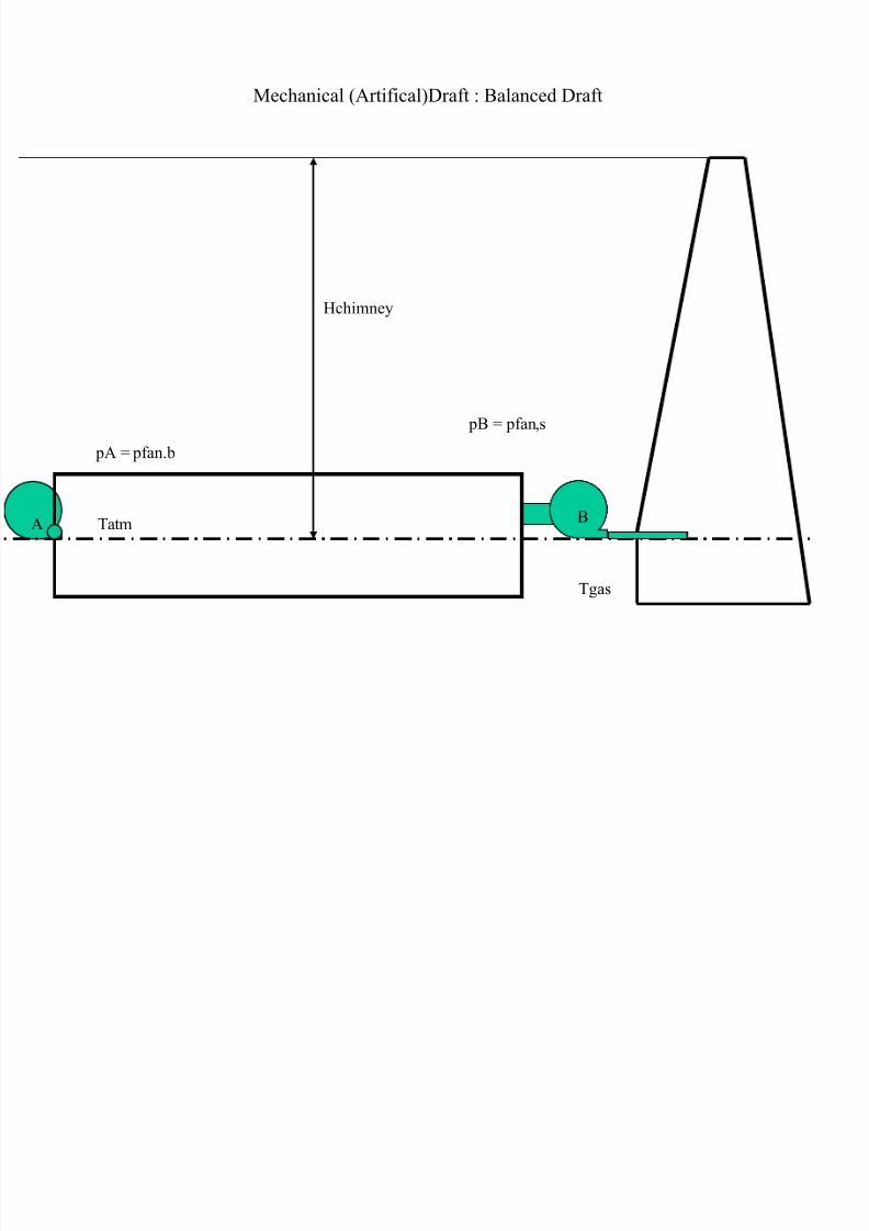
Mechanical *Artifical)Draft - Balance" Draft
&chimney
atm
gas
A B
pB ' pfan+s
pA ' pfan.b
B

7/17/2019 Draught
http://slidepdf.com/reader/full/draught-568e9a7cbe0b6 8/45
!esistance to Air / 0as #lo$ hrough Steam
0enerator System

7/17/2019 Draught
http://slidepdf.com/reader/full/draught-568e9a7cbe0b6 9/45
(1e
21e

7/17/2019 Draught
http://slidepdf.com/reader/full/draught-568e9a7cbe0b6 10/45
Platen Super heater
!eheater
#inal Super heater
3S&
Economi4er
#urnace
5in" Bo6
7oal Pul1eri4er
# D #an
Secon"ary air "uct
P A #an
PA "uct
AP&
#lue gas "uct
7oal bun8er
7oal fee"er
Boiler "rum
9:; M5 P<5E! P3A% S0

7/17/2019 Draught
http://slidepdf.com/reader/full/draught-568e9a7cbe0b6 11/45
Pressure drop in Air and Gas uct !ystems
"ernoulli e#uation $ pressure drop across a flow passage
9
9
9
9
9
9
:
9
:
:
:
99 ρ ρ ρ
P gZ
u P
m
W gZ
u P ∆+++=
∆
∆+++
Paud L f pdl 9
9 ρ =∆%rictional resistance along flow path&
$here f ' coefficient of friction
L ' length of the "uct+ m
d dl ' equi1alent "iameter of the "uct+ m
ρ ' "ensity of air or gas calculate" at the mean gas temperature+ 8g=m>
u ' cross section a1erage 1elocity of air or gas in the "uct+ m=sec

7/17/2019 Draught
http://slidepdf.com/reader/full/draught-568e9a7cbe0b6 12/45
'#uivalent diameter for rectangular duct is given as
( )
( ) 9?.;
@9?.;
>.:ba
abd
dl +
=
9
.;
!e
C.?
.>
log
;@9?.;
+
=
dl d
k
f
where a and b are sides of the duct( mm.
The coefficient of friction for flow through tubes can be approximated as shown below(
for )*** + ,e+-*
(
-*/0
+ 123ddl4+*.*-

7/17/2019 Draught
http://slidepdf.com/reader/full/draught-568e9a7cbe0b6 13/45
5inor 6osses
Calculation of 6ocal pressure drops&
where 7p 8 local pressure drop
9 8 local resistance factor(
ρ 8 density of air or gas at the position of the pressure drop calculated( 2g3m
:
u 8 velocity of air through the fittings m3s.
Pau
K pl 9
9 ρ
=∆

7/17/2019 Draught
http://slidepdf.com/reader/full/draught-568e9a7cbe0b6 14/45
Pressure drop across a burner
pa
9 8 -.) for tangential burner
:.* for swirl burner
9
9u K P ρ
=∆

7/17/2019 Draught
http://slidepdf.com/reader/full/draught-568e9a7cbe0b6 15/45
Pressure drop across heating surfaces
Pressure drop across tube bundles&
;nline arrangement& 9 8 n 9*
<here n 8 number of tube rows along the flow direction
9* 8 loss coefficient for one row of tubes
9* depends on =- 8 s-3d( => 8 s>3d ( ? 8 1s- / d 4
<here s- is lateral pitch @ s> is longitudinal pitch
;f =- +8 => &
9* 8 -.)> 1=- $-4 $ *.)
? $*.>
,e $*.>
;f =- => &
9* 8 *.:> 1=- $-4 $ *.)
1? $ *.B4 $*.>
,e $*.>3?
Pau
K p bt 9
9 ρ
=∆
S:
S9

7/17/2019 Draught
http://slidepdf.com/reader/full/draught-568e9a7cbe0b6 16/45
!taggered Arrangement
The loss coefficient is obtained as
9 8 9* 1n-4
<here 9* is the coefficient of frictional resistance of one row of tubes
9* depends on =- 8 s-3d( ? 8 1s- / d 4 3 1s>
l / d 4
<here s> l is the diagonal tube pitch given by
s>l 8 D 1 *.>) s-
> s>
>4
and 9* can be written as(
9* 8 Cs ,e/*.>E
Cs is design parameter of the staggered ban2s
S:
S9

7/17/2019 Draught
http://slidepdf.com/reader/full/draught-568e9a7cbe0b6 17/45
%or *.-E +8 ? +8 -.E and =- 8 >.*( Cs 8 :.>
;f =- + >.*(then Cs given as
Cs 8 :.> 1F.0 $ >.E ?41> / =-4
%or ? 8 -.E $ ).>( Cs 8 *.FF1?-4>

7/17/2019 Draught
http://slidepdf.com/reader/full/draught-568e9a7cbe0b6 18/45
Cross/%low over %inned Tubes
;nline arrangement
for round fins
where =-l 8 1pitch of fin( Pf 3 diamter of tube( d4
=>ll 8 1height of fin( hf 3 diamter of tube( d4
,e 8 1 u pf 3 4
%or s#uare fine with 8 *.::
( )[ ] :9.;
:
9C.: !e:
@;@.;*C@C.;DB.9 −−−+=
σ
σ σ n
K f ll
f l
[ ] :9.;
:
!e:B?.9D;.: −−+=σ
σ n K f ll
f ll
σ

7/17/2019 Draught
http://slidepdf.com/reader/full/draught-568e9a7cbe0b6 19/45
-4 !taggered Arrangement
for round fins s-8s>8d>hf
for round fins s-8s>8>d
[ ] 9C.;B9.;
!e;.9 −−
= f l n K σ
[ ] C?.;
9C.;B9.;
!eB.9 −
−−
= f ll f l n K σ σ

7/17/2019 Draught
http://slidepdf.com/reader/full/draught-568e9a7cbe0b6 20/45
Gas side pressure drop in finned/tube economiHers
Pau
K pmc9
9 ρ
=∆
7/17/2019 Draught
http://slidepdf.com/reader/full/draught-568e9a7cbe0b6 21/45
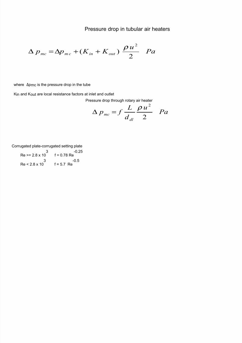
Pressure drop in tubular air heaters
where Δpmc is the pressure drop in the tube
9in and 9out are local resistance factors at inlet and outlet
Pau
K K p p out incmmc9
)*9
ρ ++∆=∆
Pressure drop through rotary air heater
Corrugated plate/corrugated setting plate
,e 8 >. x -*:
f 8 *.E ,e/*.>)
,e + >. x -*:
f 8 ).E ,e/*.)
Pau
d
L f p
dl
mc9
9 ρ
=∆

7/17/2019 Draught
http://slidepdf.com/reader/full/draught-568e9a7cbe0b6 22/45
Corrugated plate/ plane setting plate
,e 8 -.F x -*: f 8 *.0 ,e
/*.>)
,e + -.F x -*:
f 8 :: ,e/*.
Plane plate/ plane setting plate
,e 8 -.F x -*: f 8 *. :: ,e
/*.>)
,e + -.F x -*:
f 8 B*3 ,e

7/17/2019 Draught
http://slidepdf.com/reader/full/draught-568e9a7cbe0b6 23/45
Pressure "rop in "ucts oining air heater an" "ust collector
The volume flow rate of gases at the induced draft fan is determined by (
where Igf 8 volume flow rate of gases at the exit of the duct( m:
3s
Tg 8 temperature of flue gas leaving the duct(*
C
∆α 8 lea2age air ratio behind the air heater
( )
+∆+= 9B>
9B>; g g f g T V V BV α
" 8 fuel firing rate( 2g3s
where αe is the excess air ratio in the flue gas at the duct exit
; is the col" air temperature+;
7
α α
α α
∆+
∆+=
e
g e
f g
T T T
;

7/17/2019 Draught
http://slidepdf.com/reader/full/draught-568e9a7cbe0b6 24/45
Pressure drop through convective section
5ass conservation for unchanged density(
u A 8 u- A- 8 u> A>
local pressure loss( ∆p- 8
total loss( ∆p 8 ∆p- ∆p> JJJJJJJ.∆pn 8 12-- 2>
> JJJJ.. 2n
n4
where 2-- 8 2- 1A3A-4
>( 2
-> 8 2> 1A3A-4
>
999
9:
:
9
:
9
:
9
:::
u K
u
A
A K
u K p ===∆
9
9u

7/17/2019 Draught
http://slidepdf.com/reader/full/draught-568e9a7cbe0b6 25/45
Ash 7ollectors
• #ollo$ing able is use" to estimate the pressure "rop in Ash
collectors.
• 7yclone- :? , 9; m=s ; , ;F ?;; , :;;; Pa
• ESP- :, 9 m=s F :;; , 9;; Pa

7/17/2019 Draught
http://slidepdf.com/reader/full/draught-568e9a7cbe0b6 26/45
Pressure rop through !tac2
where ∆pst 8 stac2 pressure drop( Pa
f 8 friction factor
6st 8 height of the chimney( m
8 diamter of the chimney ( m
9c 8 resistance factor at the stac2 outlet
ρ 8 gas density in the stac2( 2g3m:
uc8 gas velocity at the chimney outlet( m3s
9
9cc
st
syu K
L f p ρ
++=∆

7/17/2019 Draught
http://slidepdf.com/reader/full/draught-568e9a7cbe0b6 27/45
Total gas side pressure drop
Pa
where Σ∆p- 8 total pressure drop from the furnace outlet to the
dust collector( Pa
Σ∆p> 8 pressure drop after the dust collector( Pa
µ 8 ash content in the glue gas( 2g32g
pa v 8 average pressure of the gas( Pa
pg o 8 flue gas density at standard conditions( 2g3Nm:
[ ]
Σ∆++Σ∆=∆
a!
o g
sy P
p p p :;:>9?9A>.:
):* 9:
ρ µ

7/17/2019 Draught
http://slidepdf.com/reader/full/draught-568e9a7cbe0b6 28/45
The ash fraction of the flue gas calculated as(
where αf h 8 ratio of fly ash in flue gas to total ash in the fuel
A 8 ash content of wor2ing mass( K
Ig 8 average volume of gas from furnace to dust collector calculated from the average excess air ratio( Nm :32g of
fuel
g o g
" f
V
A
ρ
α µ
:;;
=

7/17/2019 Draught
http://slidepdf.com/reader/full/draught-568e9a7cbe0b6 29/45
The pressure drop from the balance point of the furnace to the chimney base is
∆prest 8 ∆pexit ∆pgas $∆ pnd
where ∆pexit 8 pressure drop up to the boiler outlet

7/17/2019 Draught
http://slidepdf.com/reader/full/draught-568e9a7cbe0b6 30/45
otal losses
∆ p
Percent Boiler !ating
Burner 3osses
AP& 3osses
Ducts / "ampers losses
Air Pressure 3osses

7/17/2019 Draught
http://slidepdf.com/reader/full/draught-568e9a7cbe0b6 31/45
otal losses
∆ p
Percent Boiler !ating
#urnace+ S& / !& 3osses
Economi4er 3osses
Ducts / "ampers losses
Draught 3osses

7/17/2019 Draught
http://slidepdf.com/reader/full/draught-568e9a7cbe0b6 32/45
#D
#an
Duct AP& Duct #urnace Duct AP&Bac8
pass
ESPID
#an
7himney D u c t
D u c t
Mo"eling of 9:; M5 Draught System
•
Pressure "rop calculation in air / gas path an" itscomparison $ith "esign 1alue.• Assessment of ID an" #D fan po$er as a function of
furnace pressure.• Assessment of effecti1e 8inetic rate coefficient as a
function of furnace pressure.

7/17/2019 Draught
http://slidepdf.com/reader/full/draught-568e9a7cbe0b6 33/45
Pressure Variation
Duct#D #an Duct S7AP& AP& Duct5in"
Bo6
Boiler AP& ESP ID #an

7/17/2019 Draught
http://slidepdf.com/reader/full/draught-568e9a7cbe0b6 34/45
<ff Design Pressure Variation
Pressure Variation in Air & Gas Path at Part Load
/>***
/-)**
/-***
/)**
*
)**
-***
-)**
>***
>)**
- > : F ) 0 E B -* -- ->
Path Element
P r e s s u r e
( P a )
Calculated (168 MW) Desin (168 MW)
ID #anESPBoiler AP&5in"
Bo6
DuctAP&DuctS7AP&Duct#D #an

7/17/2019 Draught
http://slidepdf.com/reader/full/draught-568e9a7cbe0b6 35/45
Draught 7ontrol
7/17/2019 Draught
http://slidepdf.com/reader/full/draught-568e9a7cbe0b6 36/45
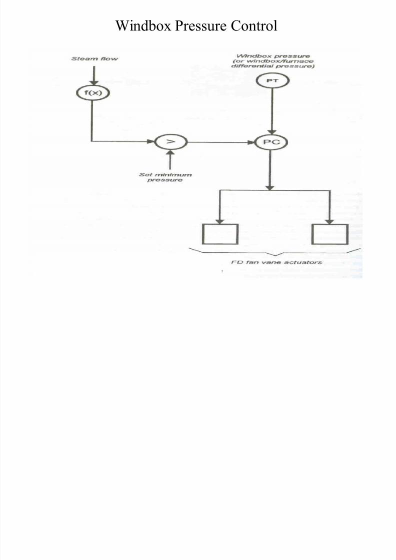
5in"bo6 Pressure 7ontrol

7/17/2019 Draught
http://slidepdf.com/reader/full/draught-568e9a7cbe0b6 37/45
7ombustion Pre"iction / 7ontrol

7/17/2019 Draught
http://slidepdf.com/reader/full/draught-568e9a7cbe0b6 38/45
7ombustion an" Draught 7ontrol
• he control of combustion in a steam generator is e6tremely critical.
• Ma6imi4ation of operational efficiency requires accurate combustion.
• #uel consumption rate shoul" e6actly match the "eman" for steam.
• he 1ariation of fuel flo$ rate shoul" be e6ecute" safely.
• he rate of energy release shoul" occur $ithout any ris8 to the plant+
personal or en1ironment.

7/17/2019 Draught
http://slidepdf.com/reader/full/draught-568e9a7cbe0b6 39/45
he Mo"el for 7ombustion 7ontrol

7/17/2019 Draught
http://slidepdf.com/reader/full/draught-568e9a7cbe0b6 40/45
Parallel 7ontrol of #uel / Air #lo$ !ate

7/17/2019 Draught
http://slidepdf.com/reader/full/draught-568e9a7cbe0b6 41/45
#lo$ !atio 7ontrol - #uel 3ea"
#l ! i 7 l # l 3 "

7/17/2019 Draught
http://slidepdf.com/reader/full/draught-568e9a7cbe0b6 42/45
#lo$ !atio 7ontrol - #uel 3ea"
G
Σ

7/17/2019 Draught
http://slidepdf.com/reader/full/draught-568e9a7cbe0b6 43/45
7ross2limite" 7ontrol System

7/17/2019 Draught
http://slidepdf.com/reader/full/draught-568e9a7cbe0b6 44/45
<6ygen rimming of #uel=air ratio 7ontrol

7/17/2019 Draught
http://slidepdf.com/reader/full/draught-568e9a7cbe0b6 45/45
7ombine" 7< / <9 rimming of #uel=Air !atio 7ontrol