draining water past radon fan motors installed outsidewpb-radon.com/pdf/radon fan drainage...
TRANSCRIPT

WPB 610 346-8004 - Draining water past outside installed radon fans 1 of 21
DRAINING WATER PAST RADON FAN MOTORS INSTALLED OUTSIDE
Presented at the 2004 – AARST – 14th Annual International Radon Symposium in Newport, RI
Bill Brodhead
WPB Enterprises, Inc., 2844 Slifer Valley Rd., Riegelsville, PA USA [email protected] www.wpb-radon.com
Detail photos of installing By-Pass drains when replacing a radon fan at:
http://wpb-radon.com/radon_fan_repair.html
Lots of Radon Info at: http://wpb-radon.com/Radon_Information.html
ABSTRACT Radon fans installed on the outside have typically had shorter life spans than fans installed in attics. This shortened life has been attributed to the condensation of water in the ducting installed above the fan that drains back past the fan motor. This paper reviews the failure rates for WPB installed radon fans from 1996 to 2004. The author evaluated six different by-pass drain designs to determine their effectiveness, reduction in airflow, cost and practicality. The draining of condensation water to the outside rather than back into the system was also reviewed.
INTRODUCTION Radon fans fail prematurely from bearing failure, failure of the windings in the motor or capacitor failure. It has been speculated that water intrusion into the fan motor and bearings causes many of these failures. Early failure of radon fans was first noted in a paper presented by the author in 2002 at the AARST National Radon Conference in Reno, Nevada. The paper, titled “Performance of Low Wattage Fans & Small Pipe Sizes with ASD Systems”, noted that 14 RP145 fans out of 315 (4.4%) installed by WPB in 2001 and 2002 went bad and required replacement. There was an initial series of 8 bad HP2133 fans out of the 90 (8.9%) that also went bad. There were no failures with the 95 RP140s fans that were put in service at that time even though they have a similar motor as the HP2133. Since that time the fan failures have continued to be a problem for WPB. In November of 2003 WPB began installing by-pass drains on all exterior mounted fans to reduce this failure rate. No outside fans installed with by-pass drains have had failures yet.
WPB OUTSIDE SYSTEM INSTALLATION WPB installs radon systems using 4” schedule 20 PVC piping from the fan to the first suction point. In attic systems, the exhaust above the fan is typically 4” schedule 20 PVC. If the radon
WPB 610 346-8004 - Draining water past outside installed radon fans 2 of 21
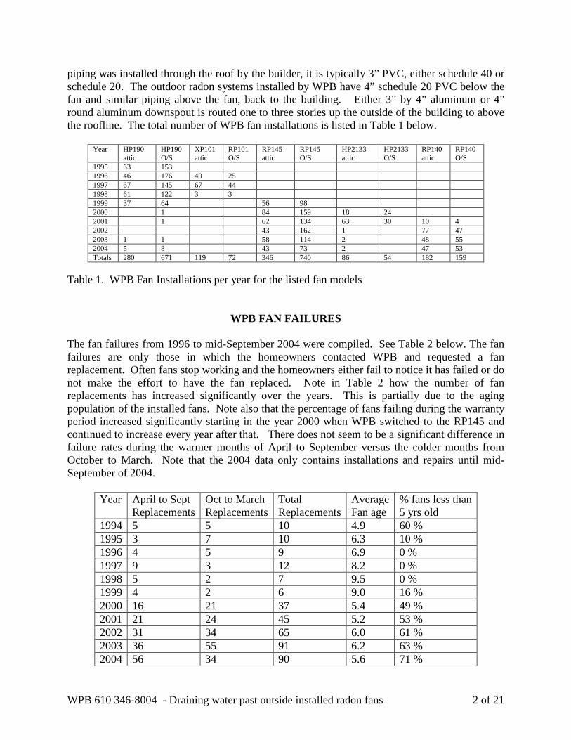
piping was installed through the roof by the builder, it is typically 3” PVC, either schedule 40 or schedule 20. The outdoor radon systems installed by WPB have 4” schedule 20 PVC below the fan and similar piping above the fan, back to the building. Either 3” by 4” aluminum or 4” round aluminum downspout is routed one to three stories up the outside of the building to above the roofline. The total number of WPB fan installations is listed in Table 1 below.
Year HP190 attic
HP190 O/S
XP101 attic
RP101 O/S
RP145 attic
RP145 O/S
HP2133 attic
HP2133 O/S
RP140 attic
RP140 O/S
1995 63 153 1996 46 176 49 25 1997 67 145 67 44 1998 61 122 3 3 1999 37 64 56 98 2000 1 84 159 18 24 2001 1 62 134 63 30 10 4 2002 43 162 1 77 47 2003 1 1 58 114 2 48 55 2004 5 8 43 73 2 47 53 Totals 280 671 119 72 346 740 86 54 182 159
Table 1. WPB Fan Installations per year for the listed fan models
WPB FAN FAILURES The fan failures from 1996 to mid-September 2004 were compiled. See Table 2 below. The fan failures are only those in which the homeowners contacted WPB and requested a fan replacement. Often fans stop working and the homeowners either fail to notice it has failed or do not make the effort to have the fan replaced. Note in Table 2 how the number of fan replacements has increased significantly over the years. This is partially due to the aging population of the installed fans. Note also that the percentage of fans failing during the warranty period increased significantly starting in the year 2000 when WPB switched to the RP145 and continued to increase every year after that. There does not seem to be a significant difference in failure rates during the warmer months of April to September versus the colder months from October to March. Note that the 2004 data only contains installations and repairs until mid-September of 2004.
Year April to Sept Replacements
Oct to March Replacements
Total Replacements
Average Fan age
% fans less than 5 yrs old
1994 5 5 10 4.9 60 % 1995 3 7 10 6.3 10 % 1996 4 5 9 6.9 0 % 1997 9 3 12 8.2 0 % 1998 5 2 7 9.5 0 % 1999 4 2 6 9.0 16 % 2000 16 21 37 5.4 49 % 2001 21 24 45 5.2 53 % 2002 31 34 65 6.0 61 % 2003 36 55 91 6.2 63 % 2004 56 34 90 5.6 71 %
WPB 610 346-8004 - Draining water past outside installed radon fans 3 of 21
Table 2. Warm versus Cold Season replacements
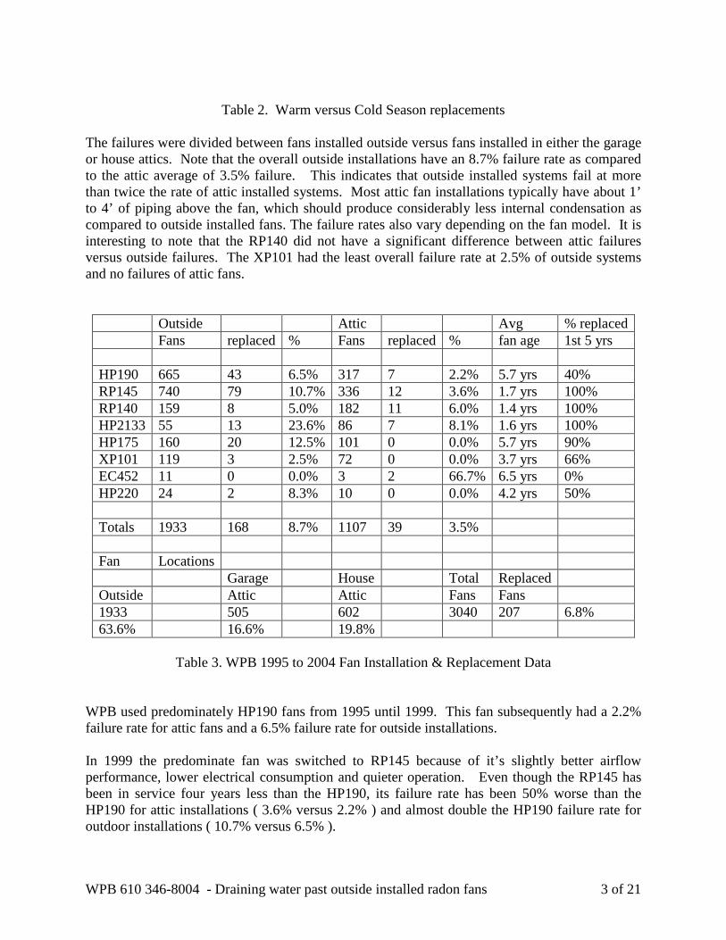
The failures were divided between fans installed outside versus fans installed in either the garage or house attics. Note that the overall outside installations have an 8.7% failure rate as compared to the attic average of 3.5% failure. This indicates that outside installed systems fail at more than twice the rate of attic installed systems. Most attic fan installations typically have about 1’ to 4’ of piping above the fan, which should produce considerably less internal condensation as compared to outside installed fans. The failure rates also vary depending on the fan model. It is interesting to note that the RP140 did not have a significant difference between attic failures versus outside failures. The XP101 had the least overall failure rate at 2.5% of outside systems and no failures of attic fans.
Outside Attic Avg % replaced Fans replaced % Fans replaced % fan age 1st 5 yrs HP190 665 43 6.5% 317 7 2.2% 5.7 yrs 40% RP145 740 79 10.7% 336 12 3.6% 1.7 yrs 100% RP140 159 8 5.0% 182 11 6.0% 1.4 yrs 100% HP2133 55 13 23.6% 86 7 8.1% 1.6 yrs 100% HP175 160 20 12.5% 101 0 0.0% 5.7 yrs 90% XP101 119 3 2.5% 72 0 0.0% 3.7 yrs 66% EC452 11 0 0.0% 3 2 66.7% 6.5 yrs 0% HP220 24 2 8.3% 10 0 0.0% 4.2 yrs 50% Totals 1933 168 8.7% 1107 39 3.5% Fan Locations Garage House Total Replaced Outside Attic Attic Fans Fans 1933 505 602 3040 207 6.8% 63.6% 16.6% 19.8%
Table 3. WPB 1995 to 2004 Fan Installation & Replacement Data
WPB used predominately HP190 fans from 1995 until 1999. This fan subsequently had a 2.2% failure rate for attic fans and a 6.5% failure rate for outside installations. In 1999 the predominate fan was switched to RP145 because of it’s slightly better airflow performance, lower electrical consumption and quieter operation. Even though the RP145 has been in service four years less than the HP190, its failure rate has been 50% worse than the HP190 for attic installations ( 3.6% versus 2.2% ) and almost double the HP190 failure rate for outdoor installations ( 10.7% versus 6.5% ).

WPB 610 346-8004 - Draining water past outside installed radon fans 4 of 21
In 2000 and 2001 the HP2133 was used for new houses with good gravel base. This fan had a high failure rate of 8.1% with attic installations and 23.6% with outdoor installations. In 2002 WPB began using the RP140 in place of the HP2133 in order to allow easy switching between the RP140 and RP145 fans outside. The RP140 exhibited a lower failure rate at 6.0% in the attic and 5.0% outside as compared to the similar HP2133. Note that the RP140 is the only fan that has a higher failure rate for attic installations versus outside systems. The motor on this fan is considerably smaller than the RP145 and HP190 fans. This fan may not be influenced by moisture. Future comparisons of its performance in attics versus outdoor installations using a by-pass drain and comparing this to its past performance may reveal whether this is the case.
AIRFLOW VERSUS FAN FAILURE The author has speculated that there may be a correlation between high or low system airflow and fan failure. WPB began recording the u-tube pressure of each job in the database starting in January 2001. This data was then sorted to determine how many high flow versus low flow attic and outside systems were installed. These numbers were then compared with all the fan replacement data that included u-tube readings to get a percentage of failures depending on the fans location and the airflow. The division between high airflow and low airflow was made at the mid-point of the suction range of each fan. If the u-tube read less than the mid-point the fan was classified as high flow. If the u-tube reading read greater than the mid-point it was classified as low flow. See Table 4 below.
Fan Type Low Flow Outside
High Flow Outside
Low flow Attic
High Flow Attic
HP2133 29.4 % 7.7 % 8.6 % 7.5 % RP140 4.3 % 5.2 % 4.9 % 6.1 % RP145 7.8 % 7.5 % 1.6 % 2.7 %
Table 4 - Fan failures divided between flow rates and location
The RP140 and RP145 do not show a significant difference in failure rates depending upon airflow rates for fan locations outside or in attics. The HP2133 does show a big difference in failure rates outside depending on flow rates. The author has no plausible explanation for this difference.
SHIPPING FAILURES In June of 2004 WPB made a bulk purchase of 100 - RP145 fans and 100 - RP140 fans. During the fan performance evaluation it was discovered that one of the new fans had loud bears. All the fans remaining from this shipment were evaluated by hand spinning the motor and listening carefully to the bearing noise. Fan bearing noise was then used to separate suspicious fans. These fans were then bench tested for bearing noise. See the results in Table 5 below.

WPB 610 346-8004 - Draining water past outside installed radon fans 5 of 21
Fan Type Bad Bearings Good Bearings % Bad RP145 21 80 20.8% RP140 11 62 15.1%
Table 5 - New Fans with Bad Bearings
These fans were returned to the manufacturer. The manufacturer tested several fans to determine if shipping could cause bearing failure. It was found that the RP140 fans if dropped on their side on to a concrete floor from three or four feet could cause bearings to become loud. The manufacturer is still trying to determine the reason for shipping caused failures for the RP145 fans. FanTech had discovered the same problem a few years previously and began shipping their fans in double layered cardboard boxes to correct this problem. It should be noted that the HP2133 fans were only shipped in standard single layer boxes which may explain their excessive failure rate. RadonAway claims that they have now redesigned their shipping box for the RP140’s to minimize this problem.
PDS - HYDRO-SEP BY-PASS DRAIN
There are two commercially available by-pass drains. The oldest commercial by-pass drain is manufactured by PDS and called the “Hydro-Sep”. This drain is actually a 2” to 3” schedule 40 PVC adaptor glued into a schedule 40 - 4” PVC pipe. Holes are drained around the perimeter of the 4” pipe to allow water to drain out directly over the fan. The velocity of the air flow actually prevents sub-slab exhaust air from escaping out the drain holes. The water, however, drains out directly onto the fan below it. WPB has not installed this by-pass drain because in the winter this drain would likely cause large icicles to hang from the fan housing. Although this would not harm the fan, it would appear as a malfunction to the homeowner. In addition the 2” inner chamber would reduce the fan capacity to move air in high flow situations.
2” pipe inside 4”
Drain holes” 12”
Figure 1 - PDS Hydro-Sep

WPB 610 346-8004 - Draining water past outside installed radon fans 6 of 21
RADONAWAY BY-PASS DRAIN A by-pass drain design is recommended in the RadonAway RP Series Installation Instructions. The instructions recommend installing a by-pass drain if there is the possibility for excessive condensation in the exhaust duct above the fan. The installation instructions explain that excessive internal condensation is due to a combination of sub-slab moisture, cold climate, long lengths of duct and duct materials that conduct heat easily, such as thin PVC piping and aluminum. A description and drawing of a fan drainage assembly is included in the instructions. See Figure 2 below. The RadonAway drain uses a reverse Y fitting above the fan to capture exhaust condensation and rain water intrusion. The water is drained back into the piping below the fan. The literature mentions that the drain may need to be insulated to prevent freezing. The aesthetic draw- back with this design is that it holds the fan assembly about 3 1/2” or more away from the building as compared to other designs.
Solid Cap with 3/4” coupling threaded into
bottom
PVC Y-Fitting
3/4” rigid PVC
Figure 2 - RadonAway Drain
WPB 610 346-8004 - Draining water past outside installed radon fans 7 of 21
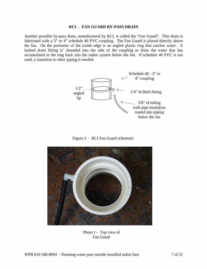
RCI - FAN GUARD BY-PASS DRAIN Another possible by-pass drain, manufactured by RCI, is called the “Fan Guard”. This drain is fabricated with a 3” or 4” schedule 40 PVC coupling. The Fan Guard is placed directly above the fan. On the perimeter of the inside edge is an angled plastic ring that catches water. A barbed drain fitting is` threaded into the side of the coupling to drain the water that has accumulated in the ring back into the radon system below the fan. If schedule 40 PVC is not used, a transition to other piping is needed.
1/2” angled
lip
Schedule 40 - 3” or 4” coupling
1/4” id Barb fitting
3/8” id tubing with pipe insulation routed into piping
below the fan
Figure 3 - RCI Fan Guard schematic
Photo 1 - Top view of Fan Guard

WPB 610 346-8004 - Draining water past outside installed radon fans 8 of 21
WPB - 3 TO 4 BY-PASS DRAIN A fourth possible by-pass drain is a cross between the Hydro-sep and the Fan Guard that I call the WPB 3 to 4 Drain. This drain can be made on site by gluing a schedule 20 - 4” to 3” coupling into a 4” schedule 40 straight coupling. A 1/4” id barb fitting is then threaded into the 4” schedule 40 coupling to catch water that accumulates between the 3” and 4” portions of the coupling. A drill and tap combination is available from RCI to easily create a threaded hole in the coupling. The brass barbed fitting is a 3/8” barb with a 1/4” male NPT thread. The tubing can be clear 3/8” vinyl tubing since it will be covered by the pipe insulation. The pipe insulation needs to be rated for outdoor use and is 1/2” id with 3/8” wall thickness. Common interior pipe insulation is not suitable because it will degrade in sunlight.
1/4” id Barb fitting
Schedule 40 - 4” coupling with schedule 20 4” to 3”
coupling 4” coupling
3/8” id tubing with pipe insulation that is routed into
piping below the fan
Figure 4 - WPB 3 to 4 Drain
Photo 2 - Top view of 3 to 4 drain

WPB 610 346-8004 - Draining water past outside installed radon fans 9 of 21
DILTS BY-PASS DRAIN
A fifth by-pass drain, designed by WPB system installer Mark Dilts, uses a small piece of flashing to create a water trap inside a 45° elbow. The flashing is held in place with urethane caulking. A 1/4” id barbed fitting is threaded into the elbow just above the dam. Insulated tubing is used to drain the collected water back into the system below the fan.
Figure 5 - Dilts Drain schematic
1/4” id Barb fitting
3/8” id tubing with pipe insulation routed to
piping below fan
45° elbow
45° street elbow with street facing
down
1/2” high dam caulked
in place
Water dam made from aluminum
flashing
7/8” height
Photo 3 - Dilts water dam Photo 4 - System with Dilts by pass drain

WPB 610 346-8004 - Draining water past outside installed radon fans 10 of 21
FANTECH HP SERIES BY-PASS DRAIN The Fantech HP190 and HP175 fans have a reducer from 4 7/8” to 3 7/8” on the inlet and outlet side of the fan. If a 4” to 5” rubber boot is used, a 1/2” drain lip is created inside the boot. A 1/2” hole drilled into the side of the rubber boot, just above the lower hose clamp allows a 1/4” id barb fitting to be threaded into the boot. Insulated tubing can then be routed from the barb fitting into the PVC piping below the fan. WPB uses the HP190 for outside fan replacements so that a drain by-pass can be added without changing the original piping.
Figure 6 - FanTech HP190 Drain
3/8” id tubing with pipe insulation
routed to piping below the fan
1/4” id Barb fitting in rubber boot
4” to 5” rubber boot
Photo 5
Top view of HP190 drain
in the rubber boot

WPB 610 346-8004 - Draining water past outside installed radon fans 11 of 21
TEE FITTING AND DRAIN An alternative drain location used by some mitigators is to install a tee fitting under the fan to capture condensation and then draining this condensation by drilling a drain hole in the cap. This design does not by-pass condensation around the fan motor but it does drain the moisture collected in the exhaust piping out of the system. The concept is that this approach will dry out the moisture under the slab rather than allowing the moisture to return back to the sub-slab as the previous drainage systems do. This drying out may help maintain better communication under the slab.
WPB now uses the Dilts by-pass drain with the insulated tubing routed into the lower section of a Tee fitting installed below the fan with four 1/8” drain holes in the bottom of the cap. See photo 4 above.
GURGLE DRAIN HOLE TEST The size and location of drain holes in the cap were tested under two airflow/vacuum conditions, high flow-low pressure (113 cfm & negative 83 pascals or almost 3/8” water column) and low flow – high pressure (31 cfm & negative 387 pascals or a bit more than 12/8” water column). An RP145 radon fan was used for the test. See photo 6 below. In each case water was sprayed into the exhaust piping above the fan. See Photo 7 below. A portion of the water was blown up and out of the exhaust pipe but most of the water ran down the exhaust pipe, past the fan motor and then collected in the bottom of the tee. A damper was installed on the piping intake to control
Figure 7 - Below Fan Drain
Drain holes in cap
Tee under fan

WPB 610 346-8004 - Draining water past outside installed radon fans 12 of 21
the airflow and negative pressure in the tee. Different holes were drilled in the solid cap below the tee to determine if gurgling would occur. The negative pressure under the fan causes air to be sucked into drain holes causing a bothersome gurgling noise. See photo 8 below.
Photo 7 - Nozzle spray into exhaust
Photo 6 – Drainage test setup
Photo 8 – Drain hole test Photo 9 – Flow grid
WPB 610 346-8004 - Draining water past outside installed radon fans 13 of 21
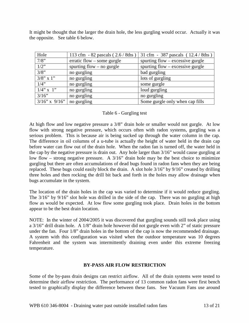
It might be thought that the larger the drain hole, the less gurgling would occur. Actually it was the opposite. See table 6 below.
Hole 113 cfm - 82 pascals ( 2.6 / 8ths ) 31 cfm - 387 pascals ( 12.4 / 8ths ) 7/8” erratic flow – some gurgle spurting flow – excessive gurgle 1/2” spurting flow – no gurgle spurting flow – excessive gurgle 3/8” no gurgling bad gurgling 3/8” x 1” no gurgling lots of gurgling 1/4” no gurgling some gurgle 1/4” x 1” no gurgling loud gurgling 3/16” no gurgling no gurgling 3/16” x 9/16” no gurgling Some gurgle only when cap fills
Table 6 - Gurgling test
At high flow and low negative pressure a 3/8” drain hole or smaller would not gurgle. At low flow with strong negative pressure, which occurs often with radon systems, gurgling was a serious problem. This is because air is being sucked up through the water column in the cap. The difference in oil columns of a u-tube is actually the height of water held in the drain cap before water can flow out of the drain hole. When the radon fan is turned off, the water held in the cap by the negative pressure is drain out. Any hole larger than 3/16” would cause gurgling at low flow – strong negative pressure. A 3/16” drain hole may be the best choice to minimize gurgling but there are often accumulations of dead bugs found in radon fans when they are being replaced. These bugs could easily block the drain. A slot hole 3/16” by 9/16” created by drilling three holes and then rocking the drill bit back and forth in the holes may allow drainage when bugs accumulate in the system. The location of the drain holes in the cap was varied to determine if it would reduce gurgling. The 3/16” by 9/16” slot hole was drilled in the side of the cap. There was no gurgling at high flow as would be expected. At low flow some gurgling took place. Drain holes in the bottom appear to be the best drain location. NOTE: In the winter of 2004/2005 it was discovered that gurgling sounds still took place using a 3/16” drill drain hole. A 1/8” drain hole however did not gurgle even with 2” of static pressure under the fan. Four 1/8” drain holes in the bottom of the cap is now the recommended drainage. A system with this configuration was visited when the outdoor temperature was 10 degrees Fahrenheit and the system was intermittently draining even under this extreme freezing temperature.
BY-PASS AIR FLOW RESTRICTION Some of the by-pass drain designs can restrict airflow. All of the drain systems were tested to determine their airflow restriction. The performance of 13 common radon fans were first bench tested to graphically display the difference between these fans. See Vacuum Fans use around

WPB 610 346-8004 - Draining water past outside installed radon fans 14 of 21
120 watts of power and produce around 4” of static pressure but their maximum airflow can actually be less than the 20 watt High Efficiency Fans. Using a Strong Vacuum Fan when high airflow is need could give no better performance than a 20 watt High Efficiency Fan, and it adds the material cost, operating cost and system noise. The High Efficiency Fans are well suited to houses with good gravel base. High Flow Fans move 50% more air than the Middle Performance Fans while using twice as much power. High Flow Fans use about 120 watts of power and tend to be considerably noisier than the Middle Performance Fans and High Efficiency Fans. The Middle Performance Fans typically use 40 to 90 watts of power. They produce 1.5 to over 2 inches of static pressure while still being capable of moving up to 150 cfm of airflow. The middle performance fans are typically used by most radon mitigators.
Fan Test with 10 feet of 4" pipe
0.0
0.5
1.0
1.5
2.0
2.5
3.0
3.5
4.0
4.5
0.0 50.0 100.0 150.0 200.0 250.0
CFM
Inch
es o
f W
ater
HP220
LegendMaverick
RP145RP140
HP2133
HP2190HP190
Eagle
GP501
RP265
XP151
XP201
Graph 1 - Fan Performance of 13 common radon fans.
High Efficiency Fans Middle Performance Fans
High Flow Fans
Strong Vacuum Fans
WPB 610 346-8004 - Draining water past outside installed radon fans 15 of 21
Hydro-Sep
WPB 3 to 4 Dilts
No By-Pass Drain
Fan Guard 0.2
0.4
0.8
1.0
1.2
1.4
1.6
25 50 75 100 125 150 175 200 0 0.0
0.6
CFM
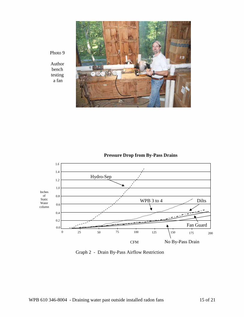
Pressure Drop from By-Pass Drains
Inches of
Static Water column
Graph 2 - Drain By-Pass Airflow Restriction
Photo 9
Author bench testing a fan
WPB 610 346-8004 - Draining water past outside installed radon fans 16 of 21
Graph 2 above displays the reduction in airflow caused by the different by-pass drains. The Hydro-Sep produces a very pronounced air flow reduction because of it’s internal 2” size. The WPB 3 to 4 by-pass starts to show some flow restriction above 50 cfm. The restriction is double the restriction of normal 4” piping at 125 cfm which is approaching the maximum airflow of most radon systems because of the other system restrictions. The Dilts and Fan Guard produce only a small pressure difference even at an airflow of 125 cfm. The HP190/HP175 by-pass created no pressure loss.
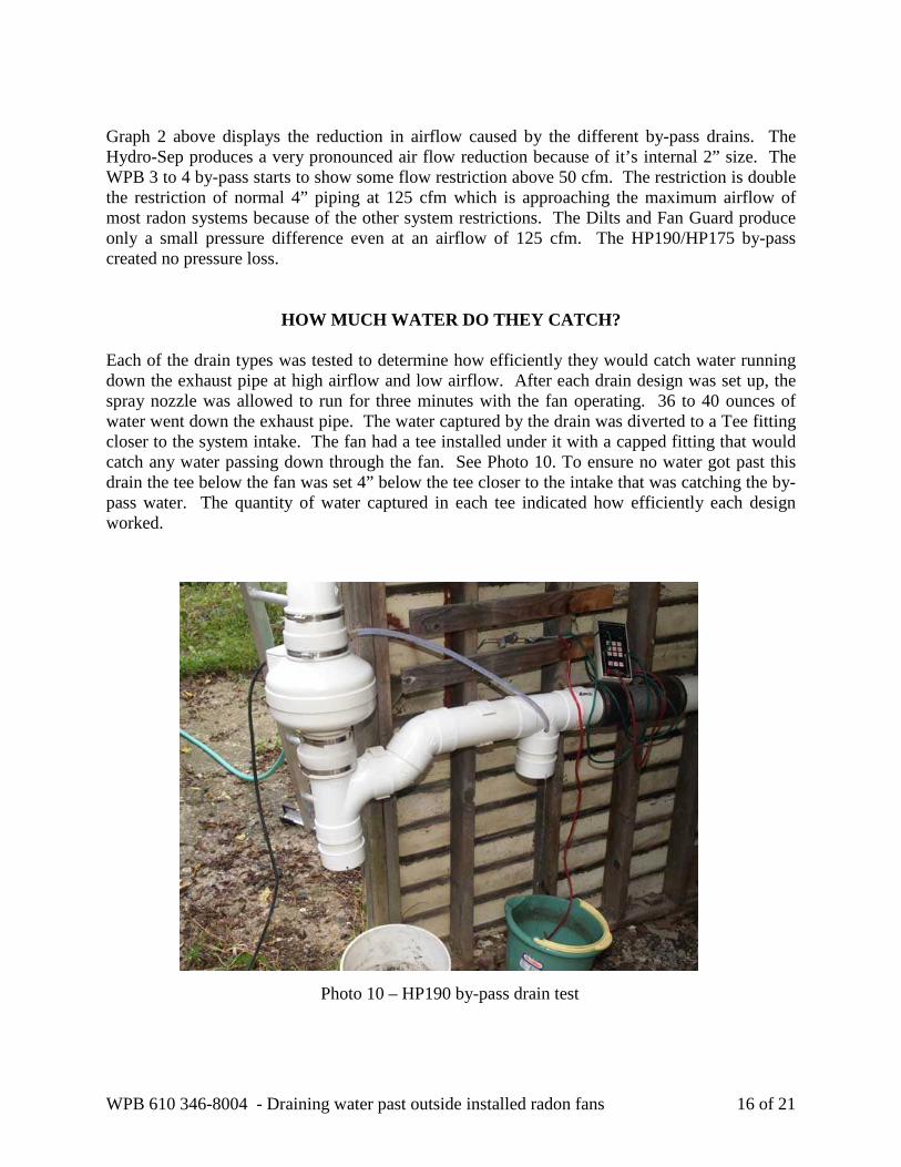
HOW MUCH WATER DO THEY CATCH? Each of the drain types was tested to determine how efficiently they would catch water running down the exhaust pipe at high airflow and low airflow. After each drain design was set up, the spray nozzle was allowed to run for three minutes with the fan operating. 36 to 40 ounces of water went down the exhaust pipe. The water captured by the drain was diverted to a Tee fitting closer to the system intake. The fan had a tee installed under it with a capped fitting that would catch any water passing down through the fan. See Photo 10. To ensure no water got past this drain the tee below the fan was set 4” below the tee closer to the intake that was catching the by-pass water. The quantity of water captured in each tee indicated how efficiently each design worked.
Photo 10 – HP190 by-pass drain test

WPB 610 346-8004 - Draining water past outside installed radon fans 17 of 21
The RCI Fan Guard, WPB 3 to 4 and the HP190 captured all the water coming down the pipe for both high and low flow. Surprisingly, the Dilts drain also capture 100% of the water at both flow rates. The RadonAway drain did well at low flow ( 97% diverted at 33 cfm ) but at high flow ( 114 cfm ) it only captured 22 oz out of 42 oz ( 52% ). An additional test was run to determine the efficiency of the RadonAway by-pass design at an in-between flow rate of 71 cfm. This time it captured 95% of the water coming down the exhaust pipe. Since most radon systems have flow rates below 100 cfm this design is still a good method for diverting water around the fan motor.
Table 7 - Percentage of water that by-passes around the fan motor
Drain Type High flow ( 112 cfm )
Oz of water
Low Flow ( 28 cfm )
Oz of water
RadonAway 52% 38 97% 33 Fan Guard 100% 38 100% 44 WPB 3to4 100% 47 100% 49 Dilts 100% 36 100% 40 HP190 100% 44 100% 46

WPB 610 346-8004 - Draining water past outside installed radon fans 18 of 21
DOES BY-PASS WATER DRAIN BACK INTO THE SUB-SLAB?
The by-pass drain systems recommended by RCI and RadonAway have the captured water routed back into the piping below the fan. A system was set up to test whether the water is actually draining back into the sub-slab or is being carried back up into the fan and out the exhaust. If the reason for installing these systems is to minimize water intrusion into the fan motor, then water moving up through the fan may be as important to control as water moving down through the fan. A measured amount of water ( 40 oz ) was placed into a 6” tall 4” pvc pipe container with a drain tube attached to the bottom. See photo 11. The water was allowed to slowly drain into the pipe just under the radon fan. The flow was restricted so that it took over an hour for all the water to drain into the pipe. The pipe had a 1/4” to the foot slope to a tee fitting, 13 inches away. The water collected in the tee was carefully measured after the draining had completed. There was exactly the same amount of water collected in the tee as when the water was drained directly into another container for both the high flow test ( 139 cfm ) and the low flow test ( 64 cfm ). This indicates that all the water appears to be draining back into the sub-soil.
HOW MUCH PITCH IS REQUIRED TO DRAIN WATER? In the RadonAway RP Series Fan Installation guide there is a recommendation for the amount of pitch required to drain water in a pipe that varies depending on pipe size and airflow rate. See Table 8 below. Notice that the requirement for 3” piping is double that of 4” piping. This has to do with airflow velocity. The velocity of air needed to move 50 cfm down a 4” round pipe is approximately the same velocity in a 3” pipe moving 25 cfm or half as much airflow. The reduction in water drainage inside a pipe is not influenced by the vacuum created by the fan but by the velocity the air is traveling at inside the piping. More important is the fact that the same amount of water in a 3” pipe will create much greater resistance than the same amount of water in a 4” pipe.
Photo 11 – Drainage test

WPB 610 346-8004 - Draining water past outside installed radon fans 19 of 21
Table 8 - RadonAway recommended pipe pitch depending upon airflow rate A test was set up to determine how much water would accumulate in 4” PVC piping under different airflows and different pitches. See the Figure 8 below. The spray nozzle was turned on with the airflow adjusted for high flow or low flow. When water would stream out of the intake opening, the nozzle would be shut off. Once there was no more water draining out of the intake opening, the fan would be turned off. Any water draining into the empty bucket under the intake opening would be the amount of water being held by the velocity of the fan. Table 9 lists all the results.
Ten feet of 4” round pipe will hold 835 ounces of water. Even with a level pipe and airflow of 143 cfm, which is a velocity of 1640 feet per minute, there was only 57 ounces of water held in the pipe. If you assume the water was equally tapering up towards the fan which would put twice the average height towards the fan it would equal 114 ounces or 14% of the volume or 1/2” of water. Once the air velocity drops below 100 cfm the water accumulation is insignificant.
Pipe Diameter
@ 25 cfm @ 50 cfm @100 cfm
3” 1/4” 3/8” 1 1/2” 4” 1/8” 1/4” 3/8” 3” 510 fpm 1019 fpm 2038 fpm 4” 286 fpm 573 fpm 1147 fpm
Figure 8 - Slope test
Pitot Tube to measure airflow
10 feet of 3” or 4” pvc piping with different pitches
Water spray nozzle sealed in top of pipe
Bucket to catch and measure system water
Damper to control airflow
Angled Intake
opening

WPB 610 346-8004 - Draining water past outside installed radon fans 20 of 21
Notice in the 4” columns of Table 9 below that the maximum airflow of around 170 cfm is able to be achieved with even 1/8” pitch. Only when the pipe is level does the maximum airflow get reduced to 143 cfm. Notice in the 3” pipe columns the maximum airflow starts off at 108 cfm and only drops about 10 to 15 % to 92 and 96 cfm at the 1/4” and 1/8” pitch levels. When the pipe is level however the airflow has dropped to a maximum of 66 cfm which is a 40% loss. Ten feet of 3” round pipe will hold 470 ounces which is almost half the volume of 4” piping. The 78 ounces held in the level pipe at 66 cfm equals about an inch of pipe loss or the downsizing of the pipe size from 3” to 2”. At high air flow this is equivalent to installing a Hydro-Sep in the pipe, with it’s two inch internal diameter.
Pipe Size
Pitch Cfm Airflow
FPM Oz of Water
Pipe Size
Pitch Cfm Airflow
FPM Oz of Water
4” 3/8” 58 665 0.5 3” 3/8” 65 1326 0.5 4” 3/8” 100 1147 1.0 3” 3/8” 79 1612 1.5 4” 3/8” 127 1456 1.5 3” 3/8” 90 1836 3 4” 3/8” 170 1949 8 3” 3/8” 108 2204 17 4” 1/4” 85 977 0.5 3” 1/4” 64 1306 0.5 4” 1/4” 103 1181 1.5 3” 1/4” 77 1571 2 4” 1/4” 126 1445 3 3” 1/4” 92 1877 5 4” 1/4” 162 1857 15 3” 1/4” 111 2265 23 4” 1/8” 61 699 0.5 3” 1/8” 40 816 0.5 4” 1/8” 85 975 2 3” 1/8” 51 1040 1 4” 1/8” 100 1147 3.5 3” 1/8” 62 1265 3 4” 1/8” 134 1537 8 3” 1/8” 75 1530 12 4” 1/8” 173 1983 20 3” 1/8” 96 1959 51 4” Level 56 642 0 3” Level 19 387 4 4” Level 84 963 5 3” Level 27 551 6 4” Level 101 1158 9 3” Level 40 816 14 4” Level 143 1640 57 3” Level 52 1061 22 3” Level 66 1346 78
Table 9 - water collected in 4” & 3” piping depending on airflow

WPB 610 346-8004 - Draining water past outside installed radon fans 21 of 21
COST OF BY-PASS DRAINS
The material cost for each by-pass drain was figured based on cost during the summer of 2004. There are no labor costs included. The commercial drains are obviously the most costly because of both the drain cost and shipping cost. Although these costs seem moderate, if a company installs 200 out door systems a year and uses the RCI drain it will add an additional cost of $2656 per year. This buys a lot of return postage for fans. If you are presently installing a FanTech HP fan then there is only $1.35 cost to drain it. The Dilts drain is a similar cost. The additional cost of draining the water to the outside with the tee fitting under the fan only adds an additional $1.42 in material costs.
Hydro-Sep RadonAway RCI WPB HP Drain Dilts Tee Drain $ 23.68 $ 4.34 $ 13.28 $ 4.29 $ 1.35 $ 1.63 $ 1.42
CONCLUSION The obvious conclusion is that outside fans have a shorter life as compared to attic installations and by-pass drains work. The by-pass drains are also not difficult or costly to install. Whether the water by-passed around the fan will extend the life of the radon fan is still to be determined. In most cases the fan is still operating in a very humid condition. Some fan failure is due to the quality of the fan motor and it’s design shape. Another factor is how much abuse the fan motor received before it was installed. Draining the by-passed water outside the fan system may reduce overall sub-slab moisture and therefore extend fan life or it may have little effect because of the constant replacement of moisture in the sub-soil from rainfall or other sources. The fan performance test indicates that there are groups of fans that are very close in performance and can be interchanged if one particular fan model is not giving the expected fan life. Pitching all radon pipes back to the suction holes although recommended may not be necessary, especially for 4” piping. It would still be recommended to slope 1/8” to 1/4” per foot to the first suction hole. Any reverse pitches are still not recommended. Note: By-pass drains have been installed on WPB outdoor radon fans for since the fall of 2003. As of July 2005, WPB has not had a single radon fan failure with a fan that has a by-pass drain. The only fan installed outside without a by-pass drain during this period failed. Failed fans installed outside are now routinely replaced with by-pass drains.
Table 10 - Additional material cost using 4” schedule 20 pvc