drainage report - garfield county, colorado · drainage analysis and design criteria ... this...
TRANSCRIPT
760 Horizon Drive, Suite 102 | Grand Junction, CO 81506 | TEL 970.263.7800 | FAX 970.263.7456
Drainage Report
PDC Energy Metcalf Soil Treatment Facility
OA Project No. 013-0036


DRAINAGE REPORT
PDC METCALF
CENTRALIZED SOIL TREATMENT FACILITY GARFIELD COUNTY, COLORADO
PREPARED FOR: PDC ENERGY, INC
1775 SHERMAN ST, STE 3000 DENVER, CO 80203 PH: (303) 860-5800
CONTACT: ED WINTERS
PREPARED BY: OLSSON ASSOCIATES
826 21 ½ ROAD GRAND JUNCTION, CO 81505
PH: (970) 263-7800 CONTACT: WYATT E. POPP, PE
APRIL 15, 2013
OLSSON ASSOCIATES PROJECT NO. 013-0036


DRAINAGE REPORT
TABLE OF CONTENTS I. INTRODUCTION ...................................................................................................................... 1
A. Background ........................................................................................................................... 1
B. Project Location ..................................................................................................................... 1
C. Property Description .............................................................................................................. 2
D. Previous Investigations .......................................................................................................... 2
II. DRAINAGE SYSTEM DESCRIPTION ...................................................................................... 2
A. Existing Drainage Conditions ................................................................................................. 2
B. Master Drainage Plan ............................................................................................................ 2
C. Offsite Tributary Area ............................................................................................................ 2
D. Proposed Drainage System Description ................................................................................ 2
E. Drainage Facility Maintenance .............................................................................................. 3
III. DRAINAGE ANALYSIS AND DESIGN CRITERIA ................................................................. 3
A. Regulations ........................................................................................................................... 3
B. Development Criteria ............................................................................................................. 3
C. Hydrologic Criteria ................................................................................................................. 4
D. Hydraulic Criteria ................................................................................................................... 4
IV. POST-CONSTRUCTION STORMWATER MANAGEMENT .................................................. 4
A. Stormwater Quality Control Measures ................................................................................... 4
B. Calculations ........................................................................................................................... 4
V. CONCLUSIONS ........................................................................................................................ 4
A. Compliance ........................................................................................................................... 4
B. Design Effectiveness ............................................................................................................. 4
C. Areas in Flood Hazard Zone .................................................................................................. 4
VI. REFERENCES ...................................................................................................................... 4
APPENDIX A: MAPS AND EXHIBITS ............................................................................................. 1
APPENDIX B: HYDROLOGIC CALCULATIONS ............................................................................. 2
APPENDIX C: HYDRAULIC CALCULATIONS ................................................................................ 3
PDC Metcalf Centralized Soil Treatment Facility Garfield County, CO 013-0036


1
I. INTRODUCTION
A. Background This Drainage Report has been prepared for PDC Energy’s (PDC) Centralized Soil Treatment Facility (the SITE) by Olsson Associates. This report evaluates the SITE’s historic drainage patterns, analyzes the change in stormwater quantity/quality associated with proposed development, and provides design to alleviate the impacts of increased stormwater runoff due to the proposed development. This report and plans are designed to bring the SITE into compliance with the COGCC rule stating, “Surface water diversion structures, including, but not limited to berms and ditches, shall be constructed to accommodate a one hundred (100) year, twenty-four (24) hour event. The facility shall be designed and constructed with a run-on control system to prevent flow onto the facility during peak discharge and a run-off control system to contain the water volume from a twenty-five (25) year, twenty-four (24) hour storm.” The design of proposed structures and associated recommendations presented herein are intended to satisfy SITE-specific storm water regulations of the COGCC.
B. Project Location The SITE is located in Section 24, Township 7 South, Range 96 West of the Sixth Principal Meridian, County of Garfield, State of Colorado. Refer to Figure 1 for project location. The SITE is located between Parachute and De Beque, southwest of the Parachute exit, on the south side of I-70, along CR 300 (Stone Quarry Rd).
Figure 1: Vicinity Map
PROJECT LOCATION
PDC Metcalf Centralized Soil Treatment Facility Garfield County, CO 013-0036

2
C. Property Description The west boundary of the SITE is the 30-foot buffer zone of an existing underground pipeline. The east boundary is formed by the toe of the steep slope on the east side of the site. Other project boundaries are formed by site constraints.
D. Previous Investigations
To our knowledge, no previous drainage studies have been approved for the SITE.
II. DRAINAGE SYSTEM DESCRIPTION
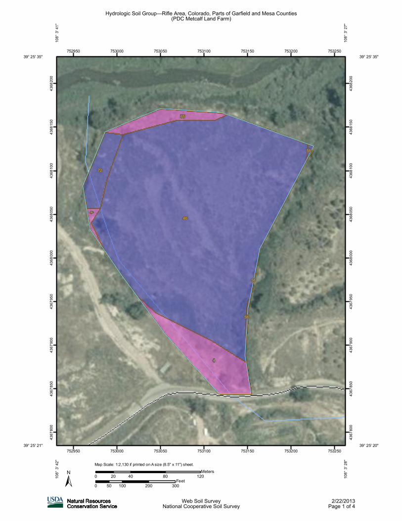
A. Existing Drainage Conditions The SITE drains to the Colorado River on the north side of the SITE via swales. Refer to the Location Map in Appendix A for the SITE location relative to major tributary drainage ways. The existing SITE consists of natural swales and mountainous terrain. The SITE generally slopes from east to the west with slopes varying from 2% up to 50%. The existing ground cover is primarily bare ground. The soils in the drainage area belong to the Hydrologic Soils Group B, soil that is moderately drained and has a moderate runoff potential. The Hydrologic Soils Map is in the Appendix B. The SITE consists of a total area of approximately 6.4 acres. Stormwater appears to sheet-flow across the SITE to existing swales exiting the SITE un-detained.
B. Master Drainage Plan To our knowledge, no master drainage studies have analyzed the SITE.
C. Offsite Tributary Area
For the purposes of this study, all adjacent land was assumed to remain undeveloped in the foreseeable future. In existing conditions, the area east of the SITE contributes to the flow across the site. This area is approximately 20.01 acres of undisturbed land (to be known as Basin OS1).
D. Proposed Drainage System Description
The proposed drainage system was designed to divert existing off-site flows around the SITE in a diversion swale and to capture and contain all rainfall within the SITE. All flow from the off-site area will be conveyed in a diversion channel along the east edge of the SITE. This swale will be sized to convey the 100-year runoff from Basin OS1. New channels will be graded into the proposed SITE to convey flow to a retention pond at the north corner of the SITE. The channel along the access road at the south end of the
PDC Metcalf Centralized Soil Treatment Facility Garfield County, CO 013-0036
3
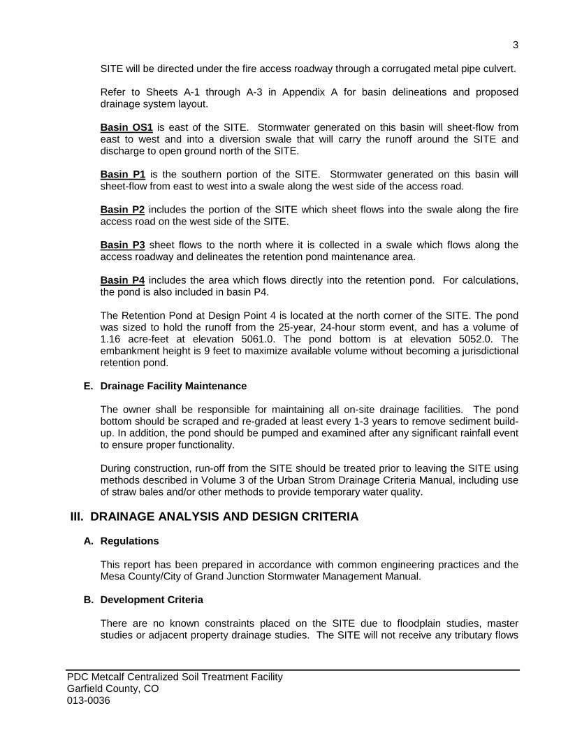
SITE will be directed under the fire access roadway through a corrugated metal pipe culvert. Refer to Sheets A-1 through A-3 in Appendix A for basin delineations and proposed drainage system layout. Basin OS1 is east of the SITE. Stormwater generated on this basin will sheet-flow from east to west and into a diversion swale that will carry the runoff around the SITE and discharge to open ground north of the SITE. Basin P1 is the southern portion of the SITE. Stormwater generated on this basin will sheet-flow from east to west into a swale along the west side of the access road. Basin P2 includes the portion of the SITE which sheet flows into the swale along the fire access road on the west side of the SITE. Basin P3 sheet flows to the north where it is collected in a swale which flows along the access roadway and delineates the retention pond maintenance area. Basin P4 includes the area which flows directly into the retention pond. For calculations, the pond is also included in basin P4. The Retention Pond at Design Point 4 is located at the north corner of the SITE. The pond was sized to hold the runoff from the 25-year, 24-hour storm event, and has a volume of 1.16 acre-feet at elevation 5061.0. The pond bottom is at elevation 5052.0. The embankment height is 9 feet to maximize available volume without becoming a jurisdictional retention pond.
E. Drainage Facility Maintenance
The owner shall be responsible for maintaining all on-site drainage facilities. The pond bottom should be scraped and re-graded at least every 1-3 years to remove sediment build-up. In addition, the pond should be pumped and examined after any significant rainfall event to ensure proper functionality. During construction, run-off from the SITE should be treated prior to leaving the SITE using methods described in Volume 3 of the Urban Strom Drainage Criteria Manual, including use of straw bales and/or other methods to provide temporary water quality.
III. DRAINAGE ANALYSIS AND DESIGN CRITERIA
A. Regulations This report has been prepared in accordance with common engineering practices and the Mesa County/City of Grand Junction Stormwater Management Manual.
B. Development Criteria
There are no known constraints placed on the SITE due to floodplain studies, master studies or adjacent property drainage studies. The SITE will not receive any tributary flows
PDC Metcalf Centralized Soil Treatment Facility Garfield County, CO 013-0036

4
from upstream land or adjacent development after development.
C. Hydrologic Criteria Hydrologic calculations have been prepared in accordance with common engineering practices. Refer to Appendix B for all hydrologic calculations.
D. Hydraulic Criteria Hydraulic calculations have been prepared in accordance with common engineering practices and the Mesa County/City of Grand Junction Stormwater Management Manual. Refer to Appendix C for all hydraulic calculations.
IV. POST-CONSTRUCTION STORMWATER MANAGEMENT
A. Stormwater Quality Control Measures The proposed riprap lined drainage swales will provide a means for stormwater to be routed around and through the SITE during all post-construction storm events. In this manner, stormwater quality control measures will not be needed because developed run-off rates are equivalent to existing condition run-off rates with little change in impervious area.
B. Calculations
Refer to Appendix B for developed condition hydrologic calculations.
V. CONCLUSIONS
A. Compliance
This report has been prepared in accordance with common engineering practices and the Mesa County/City of Grand Junction Stormwater Management Manual.
B. Design Effectiveness Proper implementation of the proposed measures outlined in this report will alleviate the direct impacts of stormwater run-off on adjacent, downstream lands.
C. Areas in Flood Hazard Zone The SITE is not within a FEMA-designated flood hazard zone and is designated as Zone D.
VI. REFERENCES
1) Mesa County/City of Grand Junction Stormwater Management Manual, December 2007. 2) Urban Storm Drainage Criteria Manual, Urban Drainage and Flood Control District,
November 2010.
PDC Metcalf Centralized Soil Treatment Facility Garfield County, CO 013-0036
APPENDIX A: MAPS AND EXHIBITS
PDC Metcalf Centralized Soil Treatment Facility Garfield County, CO 013-0036


24
2322
19 20
2930252627
131415
121110
1817
87
7S 96W7S 95W
SHEET
RE
VIS
ION
S
NO
.R
EV
.D
ATE
RE
VIS
ION
S D
ES
CR
IPTI
ON
project no.:
approved by:checked by:drawn by:
drawing no.:
QA/QC by:
date:
ww
w.o
lsso
nass
ocia
tes.
com
TEL
303
.237
.207
2FA
X 3
03.2
37.2
659
4690
Tab
le M
ount
ain
Driv
e, S
uite
200
Gol
den,
CO
804
03
OLSSON ASSOCIATES ASSUMESNO RESPONSIBILITY FOREXISTING UTILITY LOCATIONS(HORIZONTAL OR VERTICAL).THE EXISTING UTILITIES SHOWNON THIS DRAWING HAVE BEENPLOTTED FROM THE BESTAVAILABLE INFORMATION. IT ISHOWEVER THE RESPONSIBILITYOF THE CONTRACTOR TO FIELDVERIFY THE LOCATION OF ALLUTILITIES PRIOR TO THECOMMENCEMENT OF ANYCONSTRUCTION ACTIVITIES.
R
PD
C E
NE
RG
Y
ME
TCA
LF C
EN
TRA
LIZE
D S
OIL
TR
EA
TME
NT
FAC
ILIT
Y
GA
RFI
ELD
CO
UN
TY, C
OLO
RA
DO
2013
7
MOWPWPWP
013-0036
04.15.13
of
PROJECT SITE
LOC
ATI
ON
MA
P
3

P10.50 0.26
0.36
P21.73 0.26
0.36
P33.50 0.26
0.36
P40.63 0.26
0.36
1
2
3
4
SHEET
RE
VIS
ION
S
NO
.R
EV
.D
ATE
RE
VIS
ION
S D
ES
CR
IPTI
ON
project no.:
approved by:checked by:drawn by:
drawing no.:
QA/QC by:
date:
ww
w.o
lsso
nass
ocia
tes.
com
TEL
303
.237
.207
2FA
X 3
03.2
37.2
659
4690
Tab
le M
ount
ain
Driv
e, S
uite
200
Gol
den,
CO
804
03
OLSSON ASSOCIATES ASSUMESNO RESPONSIBILITY FOREXISTING UTILITY LOCATIONS(HORIZONTAL OR VERTICAL).THE EXISTING UTILITIES SHOWNON THIS DRAWING HAVE BEENPLOTTED FROM THE BESTAVAILABLE INFORMATION. IT ISHOWEVER THE RESPONSIBILITYOF THE CONTRACTOR TO FIELDVERIFY THE LOCATION OF ALLUTILITIES PRIOR TO THECOMMENCEMENT OF ANYCONSTRUCTION ACTIVITIES.
R
PD
C E
NE
RG
Y
ME
TCA
LF C
EN
TRA
LIZE
D S
OIL
TR
EA
TME
NT
FAC
ILIT
Y
GA
RFI
ELD
CO
UN
TY, C
OLO
RA
DO
2013
7
MOWPWPWP
013-0036
04.15.13
of
LEGEND
YP1
1
X Z
DR
AIN
AG
E P
LAN
SIT
E P
LAN
A-1

OS120.010.26
0.36
SHEET
RE
VIS
ION
S
NO
.R
EV
.D
ATE
RE
VIS
ION
S D
ES
CR
IPTI
ON
project no.:
approved by:checked by:drawn by:
drawing no.:
QA/QC by:
date:
ww
w.o
lsso
nass
ocia
tes.
com
TEL
303
.237
.207
2FA
X 3
03.2
37.2
659
4690
Tab
le M
ount
ain
Driv
e, S
uite
200
Gol
den,
CO
804
03
OLSSON ASSOCIATES ASSUMESNO RESPONSIBILITY FOREXISTING UTILITY LOCATIONS(HORIZONTAL OR VERTICAL).THE EXISTING UTILITIES SHOWNON THIS DRAWING HAVE BEENPLOTTED FROM THE BESTAVAILABLE INFORMATION. IT ISHOWEVER THE RESPONSIBILITYOF THE CONTRACTOR TO FIELDVERIFY THE LOCATION OF ALLUTILITIES PRIOR TO THECOMMENCEMENT OF ANYCONSTRUCTION ACTIVITIES.
R
PD
C E
NE
RG
Y
ME
TCA
LF C
EN
TRA
LIZE
D S
OIL
TR
EA
TME
NT
FAC
ILIT
Y
GA
RFI
ELD
CO
UN
TY, C
OLO
RA
DO
2013
7
MOWPWPWP
013-0036
04.15.13
of
LEGEND
YP1
X Z
EX
ISTI
NG
DR
AIN
AG
E B
AS
IN P
LAN
OFF
-SIT
E D
RA
INA
GE
A-2

SHEET
RE
VIS
ION
S
NO
.R
EV
.D
ATE
RE
VIS
ION
S D
ES
CR
IPTI
ON
project no.:
approved by:checked by:drawn by:
drawing no.:
QA/QC by:
date:
ww
w.o
lsso
nass
ocia
tes.
com
TEL
303
.237
.207
2FA
X 3
03.2
37.2
659
4690
Tab
le M
ount
ain
Driv
e, S
uite
200
Gol
den,
CO
804
03
OLSSON ASSOCIATES ASSUMESNO RESPONSIBILITY FOREXISTING UTILITY LOCATIONS(HORIZONTAL OR VERTICAL).THE EXISTING UTILITIES SHOWNON THIS DRAWING HAVE BEENPLOTTED FROM THE BESTAVAILABLE INFORMATION. IT ISHOWEVER THE RESPONSIBILITYOF THE CONTRACTOR TO FIELDVERIFY THE LOCATION OF ALLUTILITIES PRIOR TO THECOMMENCEMENT OF ANYCONSTRUCTION ACTIVITIES.
R
PD
C E
NE
RG
Y
ME
TCA
LF C
EN
TRA
LIZE
D S
OIL
TR
EA
TME
NT
FAC
ILIT
Y
GA
RFI
ELD
CO
UN
TY, C
OLO
RA
DO
2013
7
MOWPWPWP
013-0036
04.15.13
of
DR
AIN
AG
E P
LAN
TRA
PE
ZOID
AL
CH
AN
NE
L A
ND
CU
LVE
RT
PLA
N
LEGEND
F-1
C-1
C-1
D-1
F-1
F-2F-3
A-3

APPENDIX B: HYDROLOGIC CALCULATIONS
PDC Metcalf Centralized Soil Treatment Facility Garfield County, CO 013-0036

46
4
72
65
458
58
58
752950
752950
753000
753000
753050
753050
753100
753100
753150
753150
753200
753200
753250
753250
4367
800
4367
800
4367
850
4367
850
4367
900
4367
900
4367
950
4367
950
4368
000
4368
000
4368
050
4368
050
4368
100
4368
100
4368
150
4368
150
4368
200
4368
200
0 100 200 30050Feet
0 40 80 12020Meters
39° 25' 35''
108°
3' 27
''
39° 25' 20''
108°
3' 28
''
39° 25' 21''
39° 25' 35''10
8° 3'
42''
108°
3' 41
''
Map Scale: 1:2,130 if printed on A size (8.5" x 11") sheet.
Hydrologic Soil Group—Rifle Area, Colorado, Parts of Garfield and Mesa Counties(PDC Metcalf Land Farm)
Natural ResourcesNatural ResourcesNatural ResourcesNatural ResourcesConservation ServiceConservation ServiceConservation ServiceConservation Service
Web Soil SurveyNational Cooperative Soil Survey
2/22/2013Page 1 of 4

MAP LEGEND MAP INFORMATION
Area of Interest (AOI)Area of Interest (AOI)
SoilsSoil Map Units
Soil RatingsA
A/D
B
B/D
C
C/D
D
Not rated or not available
Political FeaturesCities
Water FeaturesStreams and Canals
TransportationRails
Interstate Highways
US Routes
Major Roads
Local Roads
Map Scale: 1:2,130 if printed on A size (8.5" × 11") sheet.
The soil surveys that comprise your AOI were mapped at 1:24,000.
Warning: Soil Map may not be valid at this scale.
Enlargement of maps beyond the scale of mapping can causemisunderstanding of the detail of mapping and accuracy of soil lineplacement. The maps do not show the small areas of contrastingsoils that could have been shown at a more detailed scale.
Please rely on the bar scale on each map sheet for accurate mapmeasurements.
Source of Map: Natural Resources Conservation ServiceWeb Soil Survey URL: http://websoilsurvey.nrcs.usda.govCoordinate System: UTM Zone 12N NAD83
This product is generated from the USDA-NRCS certified data as ofthe version date(s) listed below.
Soil Survey Area: Rifle Area, Colorado, Parts of Garfield and MesaCountiesSurvey Area Data: Version 6, Mar 25, 2008
Date(s) aerial images were photographed: 8/8/2005
The orthophoto or other base map on which the soil lines werecompiled and digitized probably differs from the backgroundimagery displayed on these maps. As a result, some minor shiftingof map unit boundaries may be evident.
Hydrologic Soil Group–Rifle Area, Colorado, Parts of Garfield and Mesa Counties(PDC Metcalf Land Farm)
Natural ResourcesConservation Service
Web Soil SurveyNational Cooperative Soil Survey
2/22/2013Page 2 of 4

Hydrologic Soil Group
Hydrologic Soil Group— Summary by Map Unit — Rifle Area, Colorado, Parts of Garfield and Mesa Counties (CO683)
Map unit symbol Map unit name Rating Acres in AOI Percent of AOI
4 Arvada loam, 6 to 20 percent slopes D 1.1 8.5%
46 Nihill channery loam, 1 to 6 percent slopes B 10.6 84.3%
58 Potts-Ildefonso complex, 12 to 25 percentslopes
B 0.0 0.4%
65 Torrifluvents, nearly level D 0.4 3.1%
72 Wann sandy loam, 1 to 3 percent slopes B 0.5 3.7%
Totals for Area of Interest 12.6 100.0%
Description
Hydrologic soil groups are based on estimates of runoff potential. Soils areassigned to one of four groups according to the rate of water infiltration when thesoils are not protected by vegetation, are thoroughly wet, and receive precipitationfrom long-duration storms.
The soils in the United States are assigned to four groups (A, B, C, and D) andthree dual classes (A/D, B/D, and C/D). The groups are defined as follows:
Group A. Soils having a high infiltration rate (low runoff potential) when thoroughlywet. These consist mainly of deep, well drained to excessively drained sands orgravelly sands. These soils have a high rate of water transmission.
Group B. Soils having a moderate infiltration rate when thoroughly wet. Theseconsist chiefly of moderately deep or deep, moderately well drained or well drainedsoils that have moderately fine texture to moderately coarse texture. These soilshave a moderate rate of water transmission.
Group C. Soils having a slow infiltration rate when thoroughly wet. These consistchiefly of soils having a layer that impedes the downward movement of water orsoils of moderately fine texture or fine texture. These soils have a slow rate of watertransmission.
Group D. Soils having a very slow infiltration rate (high runoff potential) whenthoroughly wet. These consist chiefly of clays that have a high shrink-swellpotential, soils that have a high water table, soils that have a claypan or clay layerat or near the surface, and soils that are shallow over nearly impervious material.These soils have a very slow rate of water transmission.
If a soil is assigned to a dual hydrologic group (A/D, B/D, or C/D), the first letter isfor drained areas and the second is for undrained areas. Only the soils that in theirnatural condition are in group D are assigned to dual classes.
Hydrologic Soil Group–Rifle Area, Colorado, Parts of Garfield and MesaCounties
PDC Metcalf Land Farm
Natural ResourcesConservation Service
Web Soil SurveyNational Cooperative Soil Survey
2/22/2013Page 3 of 4

Rating Options
Aggregation Method: Dominant Condition
Component Percent Cutoff: None Specified
Tie-break Rule: Higher
Hydrologic Soil Group–Rifle Area, Colorado, Parts of Garfield and MesaCounties
PDC Metcalf Land Farm
Natural ResourcesConservation Service
Web Soil SurveyNational Cooperative Soil Survey
2/22/2013Page 4 of 4

PDC Landfarm3/4/20134:21 PM
DESCRIPTION PDC Metcalf Land FarmULTIMATE OR INITIAL Draft Drainage StudyDESIGNER MEOCITY OR COUNTY Garfield County
1 HOUR DESIGN POINT RAINFALL VALUES-NOAA ATLAS FOR COLORADO
2 YR 0.655 YR 0.85
10 YR 1.0025 YR 1.2550 YR 1.40
100 YR 1.66
24 HOUR DESIGN POINT RAINFALL VALUES-NOAA ATLAS FOR COLORADO
2 YR 1.205 YR 1.50
10 YR 1.8025 YR 2.1050 YR 2.40
100 YR 2.60

PDC Metcalf Soil Treatment Facility
2-yr 5-yr 10-yr 25-yr 50-yr 100-yr6-hr 0.90 2.00
24-hr 1.20 1.50 1.80 2.10 2.40 2.601-hr 0.65 0.85 1.00 1.25 1.40 1.66
Return Period
Dura
tion

Olsson Associates3/4/2013
PDC Metcalf Soil Treatment Facility 013-0036_Hydrology and Pond Vol Calcs.xlsx
COMPOSITE 'C' FACTORS (DEVELOPED)LOCATION: Garfield County Draft Drainage Study BY: MEO Soil Type: B DATE:
BASIN UNDEVELOPED DEVELOPED COMPOSITE C FACTOR % IMPERVIOUS
DESIGNATION UNDEV DEV TOTAL 2YR 5 YR 10 YR 25 YR 100 YR 2YR 5 YR 10 YR 25 YR 100 YR 2YR 5 YR 10 YR 25 YR 100 YR
Imperviousness = 2 10
P1 0.50 0.00 0.50 0.00 0.08 0.17 0.26 0.36 0.06 0.14 0.22 0.31 0.40 0.00 0.08 0.17 0.26 0.36 2.00
P2 1.73 0.00 1.73 0.00 0.08 0.17 0.26 0.36 0.06 0.14 0.22 0.31 0.40 0.00 0.08 0.17 0.26 0.36 2.00
P3 3.50 0.00 3.50 0.00 0.08 0.17 0.26 0.36 0.06 0.14 0.22 0.31 0.40 0.00 0.08 0.17 0.26 0.36 2.00
.
P4 0.63 0.00 0.63 0.00 0.08 0.17 0.26 0.36 0.06 0.14 0.22 0.31 0.40 0.00 0.08 0.17 0.26 0.36 2.00
OS1 20.01 0.00 20.01 0.00 0.08 0.17 0.26 0.36 0.06 0.14 0.22 0.31 0.40 0.00 0.08 0.17 0.26 0.36 2.00
COMPOSITE I, %
2.00
3/4/2013
TOTAL A, ac
6.36

Olsson Associates3/4/2013
PDC Metcalf Soil Treatment Facility 013-0036_Hydrology and Pond Vol Calcs.xlsx
TIME OF CONCENTRATION (DEVELOPED) REMARKS
LOCATION: Garfield County Draft Drainage Study BY: MEO DATE: 3/4/2013 FORMULAS:
SUB-BASIN DATA INIT./OVERLAND TIME (Ti) TRAVEL TIME (Tt) TOTAL Tc Check (Urbanized Basins) FINAL Tc * Ti = 1.8 (1.1-C5)L^0.5/(S^1/3)
DESIGNATION C5 AREA (AC) LENGTH (FT) SLOPE % Ti (Min.)*LAND
SURFACE LENGTH (FT) SLOPE % VEL. (FPS)** Tt(Min.) Ti+Tt(Min.) LGTH. (FT) Tc = (L/180) + 10 (minutes) ** V=Cv*(S/100)^0.5
P1 0.08 0.50 50 5.00 7.62 BARE 435 15.30 3.91 1.85 9.47 485.00 12.69 9.47
P2 0.08 1.73 20 33.00 2.57 BARE 700 4.40 2.10 5.56 8.13 720.00 14.00 8.13
P3 0.08 3.50 50 5.00 7.62 BARE 580 4.83 2.20 4.40 12.01 630.00 13.50 12.01
P4 0.08 0.63 25 2.00 7.31 BARE 165 3.30 1.82 1.51 8.82 190.00 11.06 8.82
OS1 0.08 20.01 100 3.00 12.77 BARE 2030 8.00 2.83 11.96 24.73 2130.00 21.83 24.73 Approx slope based on USGS Quad map
STANDARD FORM SF-2

Olsson Associates3/4/2013
PDC Metcalf Soil Treatment Facility 013-0036_Hydrology and Pond Vol Calcs.xlsx
STORM DRAINAGE SYSTEM DESIGN(RATIONAL METHOD PROCEDURE, STANDARD FOR SF-3)
DESIGN STORM: 25-YEAR DEVELOPED Calc. by: MEO Chk'd by: WEP
PDC Metcalf Land Farm Draft Drainage Study Garfield County Date: 3/4/2013DIRECT RUNOFF TOTAL RUNOFF DITCH TRAVEL TIME REMARKS
DE
SIG
N P
OIN
T
BA
SIN
AR
EA
(AC
)
CO
EFF
. (C
)
Tc (M
in.)
C*A
I (in
./ hr
.)
Q (
cfs)
Sum
Are
a
Tc (m
in)
I (in
./hr.)
Sum
C*A
Tota
l Q (
cfs)
SLO
PE
%
FLO
W (C
FS)
LEN
GTH
(FT)
VE
L. (F
PS
)
TRA
VE
L TI
ME
Tt
1 P1 0.50 0.26 9.47 0.13 3.50 0.45 2.8 0.45 535 1.7 5.3 Tt from DP1 to DP22 P2 1.73 0.26 8.13 0.45 3.70 1.662 2.23 14.80 2.90 0.58 1.67 Design point 2, P1+P23 P3 3.50 0.26 12.01 0.91 3.18 2.884 P4 0.63 0.26 8.82 0.16 3.60 0.584 6.36 14.80 2.90 1.65 4.77 Design point 4, P1+P2+P3+P4
OS1 20.01 0.26 24.73 5.18 2.22 11.52

Olsson Associates3/4/2013
PDC Metcalf Soil Treatment Facility 013-0036_Hydrology and Pond Vol Calcs.xlsx
STORM DRAINAGE SYSTEM DESIGN(RATIONAL METHOD PROCEDURE, STANDARD FOR SF-3)
DESIGN STORM: 100-YEAR DEVELOPED Calc. by: MEO Chk'd by: WEP
PDC Metcalf Land Farm Draft Drainage Study Garfield County Date: 3/4/2013DIRECT RUNOFF TOTAL RUNOFF DITCH TRAVEL TIME REMARKS
DE
SIG
N P
OIN
T
BA
SIN
AR
EA
(AC
)
CO
EFF
. (C
)
Tc (M
in.)
C*A
I (in
./ hr
.)
Q (
cfs)
Sum
Are
a
Tc (m
in)
I (in
./hr.)
Sum
C*A
Tota
l Q (
cfs)
SLO
PE
%
FLO
W (C
FS)
LEN
GTH
(FT)
VE
L. (F
PS
)
TRA
VE
L TI
ME
Tt
1 P1 0.50 0.36 9.47 0.18 4.64 0.84 2.8 0.84 535 1.7 5.3 Tt from DP1 to DP22 P2 1.73 0.36 8.13 0.63 4.91 3.073 2.23 14.80 3.84 0.81 3.10 Design point 2, P1+P23 P3 3.50 0.36 12.01 1.27 4.21 5.344 P4 0.63 0.36 8.82 0.23 4.76 1.08
6.36 14.80 3.84 2.30 8.83 Design point 4, P1+P2+P3+P4
OS1 20.01 0.36 24.73 7.25 2.94 21.33

Olsson Associates3/4/2013
PDC Metcalf Soil Treatment Facility 013-0036_Hydrology and Pond Vol Calcs.xlsx
Volume for Retention PondPrismoidal Method
Required VolumeV=IA ELEV. AREA VOLUME ACCUM.VOL. ACCUM.VOL. ACCUM.VOL. ACCUM. VOL.
(FT) (FT2) (FT3) (FT3) (AC.-FT.) (GAL) (BBL)5052.00 2,704 0 0 0.000 0 05053.00 3,273 2,984 2,984 0.069 22,323 5325054.00 3,877 3,571 6,555 0.150 49,036 1,1685055.00 4,515 4,192 10,747 0.247 80,396 1,9145056.00 5,183 4,845 15,592 0.358 116,642 2,7775057.00 5,877 5,526 21,118 0.485 157,985 3,762
Basin I A V 5058.00 6,596 6,233 27,351 0.628 204,615 4,872(in) (AC) (AC-FT) 5059.00 7,340 6,965 34,316 0.788 256,717 6,112
P1 2.10 0.50 0.09 5060.00 8,109 7,721 42,037 0.965 314,481 7,488P2 2.10 1.73 0.30 5061.00 8,903 8,503 50,540 1.160 378,091 9,002P3 2.10 3.50 0.61P4 2.10 0.63 0.11
Total 2.10 6.36 1.11


APPENDIX C: HYDRAULIC CALCULATIONS
PDC Metcalf Centralized Soil Treatment Facility Garfield County, CO 013-0036


Project:Channel ID:
Design Information (Input)
Channel Invert Slope So = 0.0050 ft/ftManning's n n = 0.035 Bottom Width B = 0.00 ft Left Side Slope Z1 = 3.00 ft/ftRight Side Slope Z2 = 3.00 ft/ftFreeboard Height F = 0.00 ftDesign Water Depth Y = 3.33 ft
Normal Flow Condtion (Calculated) Discharge Q = 136.26 cfsFroude Number Fr = 0.56Flow Velocity V = 4.09 fpsFlow Area A = 33.35 sq ftTop Width T = 20.00 ftWetted Perimeter P = 21.09 ftHydraulic Radius R = 1.58 ftHydraulic Depth D = 1.67 ftSpecific Energy Es = 3.59 ftCentroid of Flow Area Yo = 1.10 ftSpecific Force Fs = 3.37 kip
Normal Flow Analysis - Trapezoidal Channel
PDC CENTRALIZED SOIL TREATMENT FACILITYDiversion Swale (Maximum Discharge at Minimum Slope)
013-0036_UD-Channels_v1.04_Diversion Swale.xls, Basics 3/4/2013, 3:27 PM

Project:Channel ID:
Design Information (Input)Bottom Width B = 0.00 ft Left Side Slope Z1 = 3.00 ft/ftRight Side Slope Z2 = 3.00 ft/ftDesign Discharge Q = 21.33 cfs
Critical Flow Condition (Calculated)Critical Flow Depth Y = 1.26 ftCritical Flow Area A = 4.73 sq ftCritical Top Width T = 7.53 ftCritical Hydraulic Depth D = 0.63 ftCritical Flow Velocity V = 4.51 fpsFroude Number Fr = 1.00Critical Wetted Perimeter P = 7.94 ftCritical Hydraulic Radius R = 0.60 ftCritical (min) Specific Energy Esc = 1.57 ftCentroid on the Critical Flow Area Yoc = 0.21 ftCritical (min) Specific Force Fsc = 0.25 kip
Critical Flow Analysis - Trapezoidal Channel
PDC CENTRALIZED SOIL TREATMENT FACILITYDiversion Swale (100yr Water Depth at Minimum Slope)
013-0036_UD-Channels_v1.04_Diversion Swale.xls, Basics 3/4/2013, 3:27 PM

Project:Channel ID:
Design Information (Input)
Channel Invert Slope So = 0.0050 ft/ftManning's n n = 0.035 Bottom Width B = 0.00 ft Left Side Slope Z1 = 3.00 ft/ftRight Side Slope Z2 = 3.00 ft/ftFreeboard Height F = 0.00 ftDesign Water Depth Y = 1.67 ft
Normal Flow Condtion (Calculated) Discharge Q = 21.46 cfsFroude Number Fr = 0.50Flow Velocity V = 2.57 fpsFlow Area A = 8.34 sq ftTop Width T = 10.00 ftWetted Perimeter P = 10.54 ftHydraulic Radius R = 0.79 ftHydraulic Depth D = 0.83 ftSpecific Energy Es = 1.77 ftCentroid of Flow Area Yo = 0.55 ftSpecific Force Fs = 0.39 kip
Normal Flow Analysis - Trapezoidal Channel
PDC CENTRALIZED SOIL TREATMENT FACILITYSite Swale (Maximum Discharge at Minimum Slope)
013-0036_UD-Channels_v1.04_Site Swales.xls, Basics 3/4/2013, 3:28 PM

Project:Channel ID:
Design Information (Input)Bottom Width B = 0.00 ft Left Side Slope Z1 = 3.00 ft/ftRight Side Slope Z2 = 3.00 ft/ftDesign Discharge Q = 5.34 cfs
Critical Flow Condition (Calculated)Critical Flow Depth Y = 0.72 ftCritical Flow Area A = 1.56 sq ftCritical Top Width T = 4.32 ftCritical Hydraulic Depth D = 0.36 ftCritical Flow Velocity V = 3.43 fpsFroude Number Fr = 1.01Critical Wetted Perimeter P = 4.55 ftCritical Hydraulic Radius R = 0.34 ftCritical (min) Specific Energy Esc = 0.90 ftCentroid on the Critical Flow Area Yoc = 0.12 ftCritical (min) Specific Force Fsc = 0.05 kip
Critical Flow Analysis - Trapezoidal Channel
PDC CENTRALIZED SOIL TREATMENT FACILITYSite Swale (100yr Water Depth at Minimum Slope)
013-0036_UD-Channels_v1.04_Site Swales.xls, Basics 3/4/2013, 3:28 PM
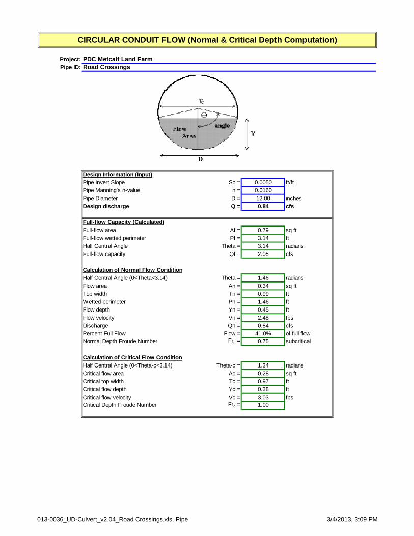
Project:Pipe ID:
Design Information (Input)Pipe Invert Slope So = 0.0050 ft/ftPipe Manning's n-value n = 0.0160Pipe Diameter D = 12.00 inchesDesign discharge Q = 0.84 cfs
Full-flow Capacity (Calculated) Full-flow area Af = 0.79 sq ftFull-flow wetted perimeter Pf = 3.14 ftHalf Central Angle Theta = 3.14 radiansFull-flow capacity Qf = 2.05 cfs
Calculation of Normal Flow Condition Half Central Angle (0<Theta<3.14) Theta = 1.46 radiansFlow area An = 0.34 sq ftTop width Tn = 0.99 ftWetted perimeter Pn = 1.46 ftFlow depth Yn = 0.45 ftFlow velocity Vn = 2.48 fpsDischarge Qn = 0.84 cfsPercent Full Flow Flow = 41.0% of full flowNormal Depth Froude Number Frn = 0.75 subcritical
Calculation of Critical Flow ConditionHalf Central Angle (0<Theta-c<3.14) Theta-c = 1.34 radiansCritical flow area Ac = 0.28 sq ftCritical top width Tc = 0.97 ftCritical flow depth Yc = 0.38 ftCritical flow velocity Vc = 3.03 fpsCritical Depth Froude Number Frc = 1.00
CIRCULAR CONDUIT FLOW (Normal & Critical Depth Computation)
PDC Metcalf Land FarmRoad Crossings
013-0036_UD-Culvert_v2.04_Road Crossings.xls, Pipe 3/4/2013, 3:09 PM

Channel ReportHydraflow Express Extension for AutoCAD® Civil 3D® 2013 by Autodesk, Inc. Tuesday, Feb 26 2013
<Name>
TriangularSide Slopes (z:1) = 3.00, 3.00Total Depth (ft) = 3.34
Invert Elev (ft) = 100.00Slope (%) = 0.50N-Value = 0.030
CalculationsCompute by: Known DepthKnown Depth (ft) = 3.33
HighlightedDepth (ft) = 3.33Q (cfs) = 158.06Area (sqft) = 33.27Velocity (ft/s) = 4.75Wetted Perim (ft) = 21.06Crit Depth, Yc (ft) = 2.81Top Width (ft) = 19.98EGL (ft) = 3.68
0 5 10 15 20 25 30 35
Elev (ft) Depth (ft)Section
99.00 -1.00
100.00 0.00
101.00 1.00
102.00 2.00
103.00 3.00
104.00 4.00
Reach (ft)