dragonfly 1000 · dragonfly 1000 trimaran owner’s manual uscg doc#1032257 . 0 table of contents...
TRANSCRIPT

Dragonfly 1000
Trimaran Owner’s Manual
USCG Doc#1032257

0
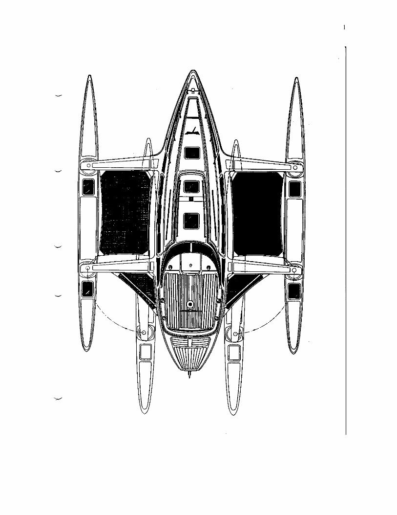
TABLE OF CONTENTS 1. Diagram
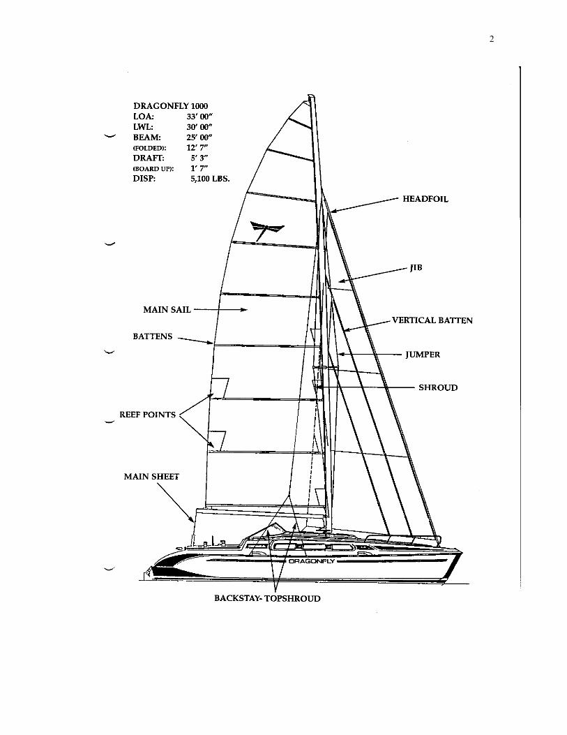
a. Deck layout b. Side view
2. Loading
a. Payload b. Storage advise
3. Swing Wing System
a. Use, advice 4. Sail Handling
a. Main, Backstays, reefing b. Genoa c. Barberhauler d. Hoisting the Genoa e. Wind speed general
guidelines 5. Kick-up Centerboard and Rudder
a. Purpose b. Use, Access c. Diagrams
6. Electrical System
a. DC and AC systems b. Charging c. AC 110V shore power d. General Advice e. Diagram of system
7. Fresh Water system
a. Tank b. Electric pump c. Sinks d. Shower e. Water heater
f. Diagram of system
8. Waste System
a. Toilet b. Y Valve c. Holding Tank d. Using the head e. General tips f. Diagram
9. Fuel System
a. Diagram 10. Interior
a. Galley b. Cabin Heater
c. Lighting d. Berths
11. Miscellaneous
a. Bilge pumps b. Folding propeller c. Stuffing box d. Diagram
12. Launching and Storage 13. Maintenance
a. Rinse, Wash and Wax b. Rig c. Wood work d. Engine e. Manufacturers materials f. Waterstay g. Checklist
14. 1000 Specifications
1
2

3
2. LOADING
There are two basic rules for loading multihulls:
1. Keep the boat as light as possible 2. Concentrate heavy items in the center of the boat.
It is important not to carry unnecessary gear. We recommend that you go through the storage lockers several times per year to look for and remove unnecessary gear, preventing the build-up of unnecessary weight. The ama storage areas are ideal for big, bulky light items such as fenders, sails, extra life jackets etc. Heavy items must not be carded in the amas. The maximum payload for the Dragonfly 1000 is 500kg. (1100 lb.). The maximum payload in each ama is 100kg. (220lbs). Overloading the Dragonfly 1000 can effect performance and safety.

4
3. THE SWING WING SYSTEM
Operating The Swing Wing system: Important The unique swing-wing system is designed for use only in protected areas, such as marinas, to fit into a normal slip (berth). The sails must never be hoisted when the floats are folded in. Always stow the sails before you start operating the swing-wing system. Operating the swing-wing system: Folding in the wings. 1. Pull out and prepare the endless swing-wing line. This line is found underneath the cockpit coaming and exits the coaming through a stainless steal cover situated in front of the big genoa winch. As already marked, the outhaul line, marked OUT is used for swinging the ama out and the inner line marked IN is for folding the ama in. 2. Remove the big spinnaker pole brace, without stepping onto the aft trampoline. Put the spinnaker pole into the stainless ring aft on the hull and secure it by fastening it to the eyebolt on the aft beam near the centerhull. (This eyebolt is also used as a lifting eye.) 3. Release the backstays on both sides. 4. Release the double-halyard stopper in the cockpit coaming. 5. Now crank the winch (3-4 turns of rope on the winch) on the AMA-IN line and the amas fold in. No persons are allowed on the trampoline, the wings or the floats while operating the swing-wing system. Do not force the swing if you have too much resistance. Checklist
• Double-halyard stopper open? • Line kinked, fouled or twisted in coaming? • Backstays released? • Barberhauler lines released? • Swing-wing line. Is there a kink? Is it fouled under the cockpit coaming? • Double-check your steps. Never force.
5
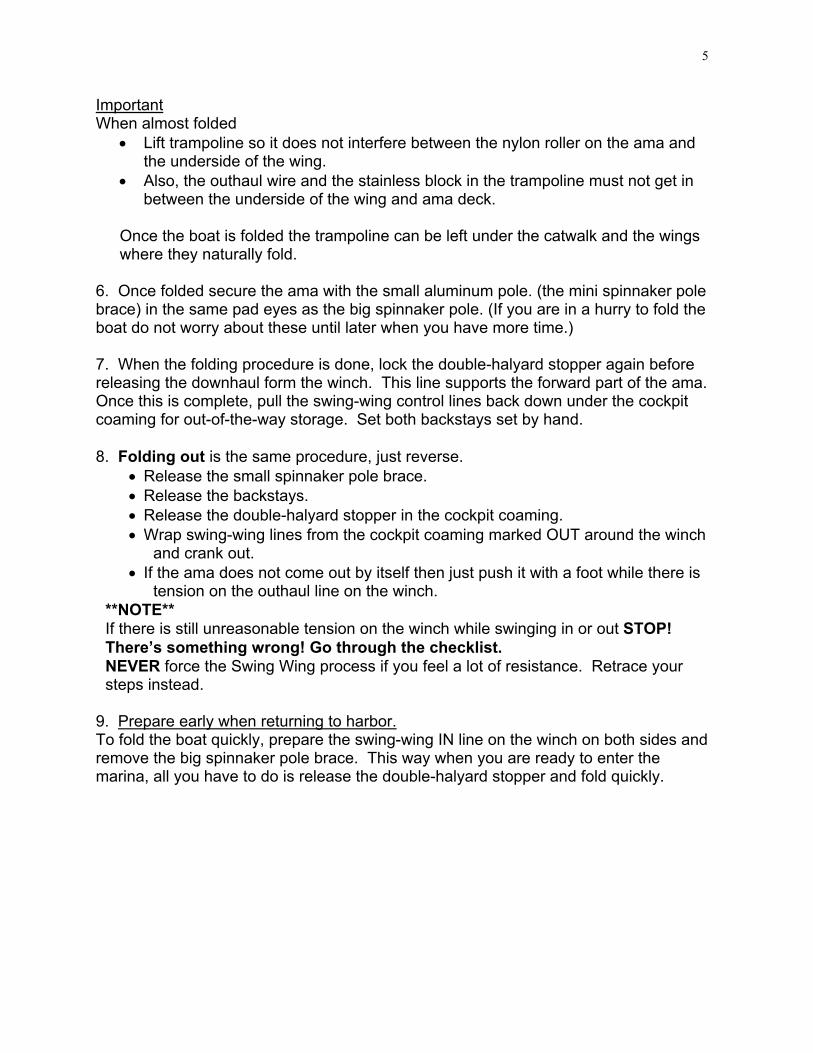
Important When almost folded
• Lift trampoline so it does not interfere between the nylon roller on the ama and the underside of the wing.
• Also, the outhaul wire and the stainless block in the trampoline must not get in between the underside of the wing and ama deck.
Once the boat is folded the trampoline can be left under the catwalk and the wings where they naturally fold.
6. Once folded secure the ama with the small aluminum pole. (the mini spinnaker pole brace) in the same pad eyes as the big spinnaker pole. (If you are in a hurry to fold the boat do not worry about these until later when you have more time.) 7. When the folding procedure is done, lock the double-halyard stopper again before releasing the downhaul form the winch. This line supports the forward part of the ama. Once this is complete, pull the swing-wing control lines back down under the cockpit coaming for out-of-the-way storage. Set both backstays set by hand. 8. Folding out is the same procedure, just reverse.
• Release the small spinnaker pole brace. • Release the backstays. • Release the double-halyard stopper in the cockpit coaming. • Wrap swing-wing lines from the cockpit coaming marked OUT around the winch
and crank out. • If the ama does not come out by itself then just push it with a foot while there is
tension on the outhaul line on the winch. **NOTE** If there is still unreasonable tension on the winch while swinging in or out STOP! There’s something wrong! Go through the checklist. NEVER force the Swing Wing process if you feel a lot of resistance. Retrace your steps instead.
9. Prepare early when returning to harbor. To fold the boat quickly, prepare the swing-wing IN line on the winch on both sides and remove the big spinnaker pole brace. This way when you are ready to enter the marina, all you have to do is release the double-halyard stopper and fold quickly.

6
4. SAIL HANDLING
1. MAINSAIL: The main will require a lot of trimming if you want to get maximum performance at all times. The mainsheet will be your key control for mainsail trimming as the boat has many speed potentials in difference wind speeds. A general rule: The leach of your main must always be straight no matter what the wind force. By standing at the end of the boom in the cockpit and looking up the leach to the mast top you will have the proper position to best judge the sail shape. From this position you will note that the leach of the sail must not be twisted off unless the boat is being pressed to hard. 2. MAINSAIL LUFF TENSION: In light air you tighten the main halyard only until the wrinkles in the sail are gone. In medium air the main halyard is tightened to remove wrinkles and be sure the luff is straight. In heavy air the main halyard is tightened hard to flatten the sail while at the same time the mainsheet should also be pulled in hard. * If you are at anchor for a short time with the mainsail up, loosen the main halyard to release the tension in the mainsail to quiet the boat. 3. MAINSHEET CAR: Multihulls have a rule: The mainsheet car must never pass the centerline of the boat to windward ... not even in light air. If the wind is increasing when sailing up wind and you find the main has too much power, try sheeting the traveler approximately 4-6" to leeward instead of slacking the mainsheet, therefore hollowing the main. Of course, don't rule out easing off the sheet in heavy air as well when you feel you are overpowered. 4. BACKSTAYS: The combined top shroud-backstay has been developed for the swing-wing system and to enable easy and quick trimming of the top shrouds. When sailing, always set the backstays the same on both sides to obtain even tension on the topshrouds.
1) Light wind, set them by hand without using a winch handle. 2) Medium wind, use the winch handle lightly to add tension. 3) Heavy wind, set the backstays on the self tailing winch as hard as you can,
turning the winch handle with only one hand. **NOTE** Double-handed grinding on winch for backstay tension can be too much strain on the rigging and the boat in general. Be careful not to "over tension" the backstays. By following the simple rules above and limiting your tensioning to the strength of one hand, you will have good control.

7
5. REEFING THE MAINSAIL: In order to reef the main release the main halyard to allow the sail to drop to the selected reef point, we recommend that you mark the main halyard for the reef one and reef two positions. Then winch in the reef line until the reef points are 10" above the boom. It is not necessary to bring the reefing points on the sail any closer to the boom. Doing so will only put excess tension on the reefing lines. The reefing lines automatically reef the luff first and then the leach. 6. TRIMMING THE GENOA: The genoa is the easiest sail to trim. Under normal conditions the genoa car on the cabin top should be positioned aft on the track. If the slot between the main and jib closes, move the genoa car aft. If the slot opens, pull the genoa car forward. The genoa cars are operated from the double-halyard stopper rope clutches on the cabin top marked outhaul. Reefing the Genoa:
• Pull the genoa car forward so that when the genoa is reefed it will be in better position for correct trim.
• For reef 1, the genoa car is placed approximately in the middle of the track. • For reef 2, car is pulled almost all the way forward.
7. BARBERHAULER: The barberhauler should not be used on the genoa when sailing close-hauled. During all other points of sail you should treat the barberhauler as you would a boom on a main. There are an infinite number of ways to trim the genoa with the barberhauler. Enjoy! 8. HOISTING THE GENOA: Before hoisting the genoa, make sure to roll some line on the drum. Turn the headfoil clockwise until you have approx. 3 feet of line left in the cockpit. This way you are able to unfurl genoa as soon as it is hoisted. There is no genoa halyard on the Dragonfly 1000. You will find an S-hook attached to a long white feeder line. This will be used to assist the spinnaker halyard in hoisting the genoa and safely bringing the spinnaker halyard back down.
• Attach the genoa to the sliding headfoil fitting. • Be sure to attach the release wire from the genoa onto the small wire strap on
the sliding headfoil fitting. • Attach the spinnaker halyard to the upper closed end of the S-hook. • Place the open end of the S-hook inside the open hole of the sliding headfoil
fitting. • Hoist the spinnaker halyard while someone feeds the genoa sail into its track. • When the halyard is all the way at the top of the headfoil, listen carefully for a
“click” letting you know the sliding headfoil fitting has just locked into place. • Release the spinnaker halyard and try to pull down on the genoa to make sure
the lock on top is actually in place. • Take the white feeder line and pull the S-hook attached to the spinnaker halyard
back down. (Sometimes you might have to step out a little to the side in order to release the S-hook.)

8
To lower the genoa, pull the release wire that is in the luff of the genoa. This will release the lock on top and allow the genoa to be pulled back down. Genoa Battens: Once the genoa is hoisted, put in the Elvstrom vertical battens. Put the battens into their corresponding pockets from the bottom, long one forward, short one aft. Close them in by fastening the Velcro seal to the sail. ***DANGER*** When unpacking the rolled up battens for the first time, BE CAREFUL! They have a tendency to explode out of their coiled position with great force.
9
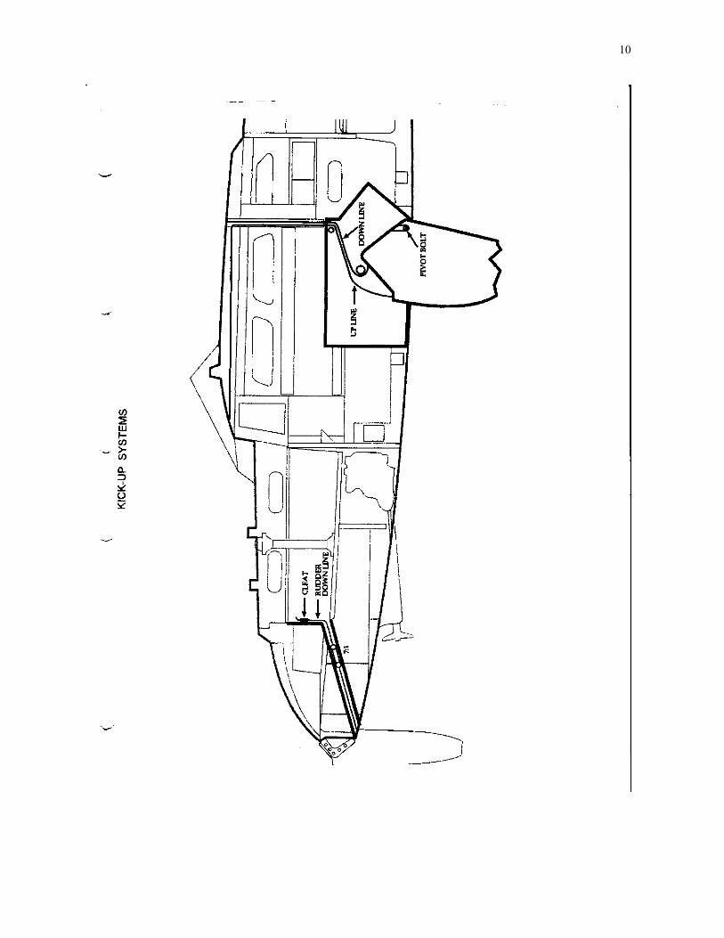
5. KICK-UP CENTERBOARD AND RUDDER
Centerboard: When maneuvering in the harbor always make sure the centerboard is down. You have much better steerage under power with the centerboard down. For optimum performance while sailing follow these guidelines:
1) Sailing to windward, keep the centerboard all the way down. 2) On a beam reach bring the centerboard half way up. 3) Downwind bring the centerboard all the way up.
Be sure that when you lower the centerboard completely, the knot on the centerboard line is all the way to the easylock rope clutch to starboard. The centerboard easylock rope clutch should be closed at all times. If the board hits ground while sailing, the tension release cleat will pop up releasing the centerboard line so that the centerboard can swing back into its case. (It really works great!!) If you detect a jam of the centerboard line, there is great easy access. Unscrew the cabin table from the centerboard trunk for easy access to the lines. To remove centerboard: To remove the centerboard the boat must be out of the water while the board is folded up into the centerboard trunk. First, unscrew the hex head screw on the centerboard which is exposed under the boat. The centerboard can then be lowered slowly using the control lines from the cockpit. Be careful when lowering the centerboard. It weighs approximately 80lbs (40kgs). Rudder: When the rudder touches the ground while sailing, the tension release cleat opens up and the board kicks up automatically. To reset the tension release cleat, lift the locking lever on top of the cleat casing and snap the cleat back into its case. The bottom portion of the rudder and centerboard are both solid fiberglass.
10

11
6. ELECTRICAL SYSTEM
The Dragonfly 1000 has a 12V DC electrical system with a 110V AC system (shore power). The DC system is based on three 65 amp 12V batteries. These batteries are located under the bottom step in the companionway. The batteries are controlled by the switch panel above the step. Of the three batteries, one is designated for the Engine only and the other two are both used for auxiliary power. All three batteries can be connected through the emergency switch on the battery control panel. The control ports have three switches, Engine, Emergency, and Auxiliary The engine battery is connected only to the engine The auxiliary battery is connected only to the auxiliary system. The emergency battery can be sent to the engine or auxiliary panel by switching on the on the emergency battery switch. Charging the batteries: There are three possible ways to charge the batteries: 1. Run the engine: The engine has a 55 amp alternator which will charge the engine battery until it is full. Once it is full, it will then switch to the auxiliary batteries. 2. Solar Panels: The two 50w panels put out a total of 8 amps. They are linked to a regulator, which is located behind the auxiliary panel. The regulator then sends the power to the auxiliary battery. 3. Shore power: The shore power system comes with a 10 amp charger located behind the refrigerator. It charges the two auxiliary batteries. The charger has an automatic shut-off switch which will prevent the batteries from being over charged, but if the boat will be left unattended for several weeks, we do not recommend having the system on. **NOTE** Shore power will charge only the auxiliary batteries, unless the emergency switch is on then it will charge all three batteries.

12
AC System: The AC system is 110VAC (same as what is in your house). This power is only available when the boat is 'plugged-in" at the dock. The system consists of a 20m cable which plugs into the 110V outlet on the dock and into the boat through the anchor well. Power runs to the 110 circuit breakers located in the locker under the sink in the head. There are 3 circuit breakers: 1. Main. (shuts off the 110 system). When the 110 system is on, a small yellow light will come on in the galley. 2. Outlet and charger: These control the power to the outlets. There is one outlet in the galley and one in the head. Through these outlets you can run your hair dryer, TV etc. This switch also controls the power to the battery charger, which is located behind the refrigerator. 3. Hot water heater: This controls the power to an outlet in the engine compartment to which the hot water heater is plugged in. (Located in the engine compartment on the port side). **DANGER** Hot water circuit breaker must be off if how water tank or fresh water tank is empty. Otherwise you will burn out the hot water heater! As a rule, you should always be aware of the state of your batteries and how much electricity is being used. It is always advisable to conserve your power while cruising. We recommend running the engine for 1 hour in the morning and 1 hour in the evening. Marine Electronmcs: The electronics are mounted above the companionway. The on/off switch is labeled on the electrical panel as 'Navigation instruments". The sending unit for the depth sounder and the paddle wheel for the knot meter are located under the v-berth.
13
14
7. Fresh Water System
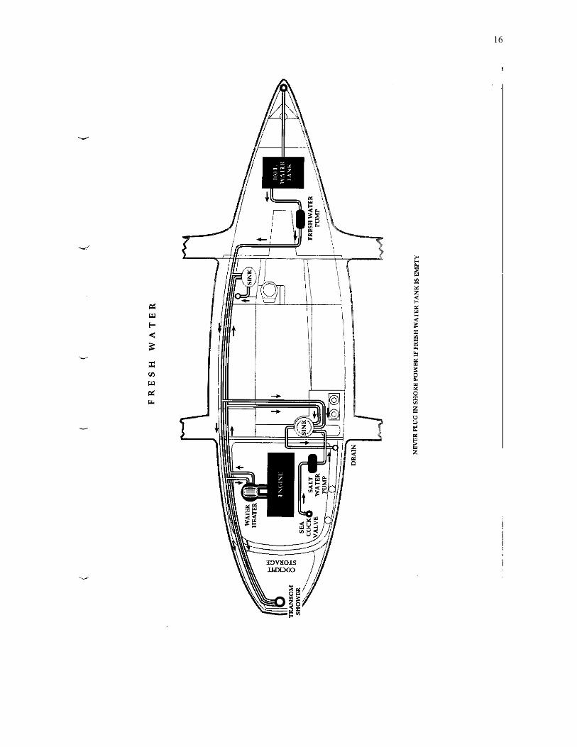
The fresh water system consists of a 100 liter (26.4 gallons) fresh water tank, a fresh water pump, two sinks, two showers and an optional water heater. 1. The fresh water tank: The fresh water tank is located under the V berth. It has a clear cover, which makes it very easy to check the amount of fresh water available. The fresh water deck fitting is located on the bow (labeled water). The tank is vented by a hose running to the port topsides near the bow. A person used to sailing cruising monohulls might be surprised that the Dragonfly 1000 does not carry more water. Unlike monohulls, multihulls are very sensitive to increases in weight. Therefore, the size of the water tank was kept small. 2. Fresh water pump: This 12V electric pump is located just aft of the fresh water tank. This pump pressurizes the entire fresh water system (hot and cold). The on/off switch is located on the main auxiliary panel. When the pump is turned on it should run for 10-15 seconds and then stop. If it continues to run or keeps turning on and off, the system is leaking. One of the faucets was probably left slightly open. Check all faucets and make sure they are closed (including transom shower). Do not let the pump run continuously or you will deplete your water supply and the pump will burn out. All pressurized water systems make it very easy to use up your entire fresh water supply quickly. It is important to remember to conserve so that your water supply lasts as long as necessary. 3. Sinks: There are two sinks. One is located in the galley, the other in the head. The sink in the head has hot and cold pressurized fresh water. It drains to a through hull fitting (above the water line) below and aft of the sink. The sink in the galley has both hot and cold pressurized fresh water and pressurized sea water. This sink drains to a through hull fitting (above the water line) just aft of the sink, in the engine compartment.

15
4. Showers: There are two showers. One of the showers is located in the head the other is located on the transom. In the head, the faucet used for the sink pulls out and becomes a hand held shower head. There is a shower curtain, which should be used to keep the lockers and their contents dry. Below the head floor is the shower's sump pump "bilge pump". The switch for the sump pump is on the front of the locker, below the sink. The pump will only go on if the water pressure is on. The discharge through hull fitting (above water line) for the sump pump is located on the port side, just below and aft of the sink. The transom shower consists of a retractable hand held shower head and hot and cold pressurized water. 5. Water Heater: The water heater provides hot water for the pressurized water system. The heater holds 20 liters (5.3 gallons), increasing the fresh water system's holding capacity to 120 liters (31.7 gallons). It heats the water in two ways.
• when the engine is running. The engine cooling water flows through a set of tubing in the heater (heating the fresh water) and then back into the engine. The engine cooling water never mixes with the fresh water.
• The heater has a 110V heating element, which can only be used when the shore power is plugged into the dock. The on/off switch is located on the 110V circuit breaker under the sink in the head.
**Caution** If the fresh water tank is empty, make sure the electric water heater switch is off at the circuit breaker or the unit will bum out!
16
17
8.
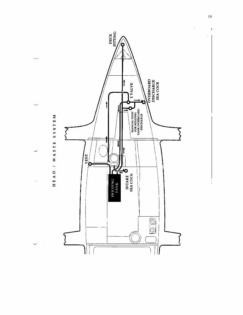
Head / Waste System There are three basic components to the Dragonfly 1000's waste system: The toilet, the Y valve and the holding tank with it's discharge pump. Use the system properly and it will work efficiently for years. 1. The toilet: The head has its own built in pump, which is used to flush the waste through the system. The pump has two controls:
1. The pump handle (to the port of the bowl) which both pumps water in and flushes water and waste out.
2. The intake control lever ( to starboard of the bowl) which allows you to shut off incoming water (up position) to pump the bowl dry.
The intake seacock is located to port of the centerboard trunk under the floor. The outlet seacock is located under the V berth on the starboard side (both easily accessible). 2. The Y valve: The Y valve (located in the V berth) enables you to discharge waste directly overboard (be careful of local regulations) or into the holding tank. The short end of the handle on the Y valve indicates the flow of waste. 3. Holding Tank: The holding tank provides temporary waste storage. It is constructed of stainless steel and holds 55 liters (14.5 gallons). The holding tank is located to port of the centerboard trunk under the cabin floor. There is access to the hose connections through the cut out section of the floor. To use the holding tank, simply switch the Y valve to holding tank. It is recommended not to pump the toilet too many times when flushing into the tank otherwise you will quickly fill the tank with sea water. Waste is removed from the holding tank in two ways.
1. A pump out station hose connected to the waste fitting on the bow will suck out the waste.
2. The manual pump (located above the Y valve) will pump out the holding tank directly overboard.
18
4. Using the head: Only put human waste and marine toilet paper into the head. All marine heads are very sensitive to clogging and it is a horrible job to unclog. Follow these steps to use the head:
1. Open the seacocks. 2. Put Y valve in appropriate position. 3. Wet bowl by flushing with intake lever in down position. (toe on the pedal) 4. Use bowl. 5. Flush with intake lever down until waste is out of bowl, then
a. if discharging overboard - another 15 times. b. if discharging into the holding tank - 7 times.
6. Pump bowl dry. Flush with intake lever up. (toe off the pedal) 5. General Tips:
1. The holding tank is made out of stainless steel to minimize odors but we recommend keeping the holding tank empty whenever possible.
2. The seacock should be closed if the boat is going to be left unattended for extended periods.
3. Never try to force a pump. This will result in destroying a seal and possibly causing a leaky head.
19
20
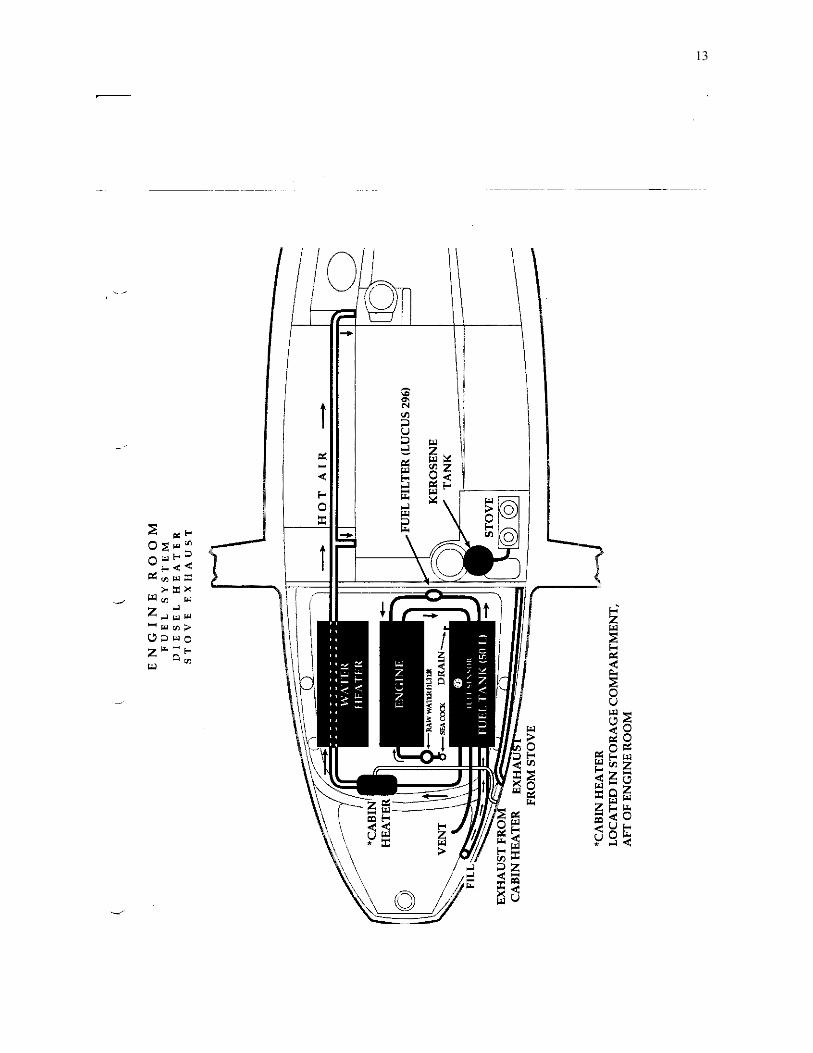
9. Fuel System
The Dragonfly 1000 has a diesel engine and only diesel fuel can be used. The fuel tank (50 liters, 13 gallons) is located in the engine room on the starboard side. The fuel system has two fuel filters.
• The primary (a Lucas 296) is located on the forward engine room bulkhead
• The secondary is located on the engine. The filters should be changed twice a year.
The fuel tank has a drain on the bottom to remove any water. To use: 1. Loosen nut 2. Open valve 3. Let drain until only diesel is coming out.
The fill deck fitting is located on the transom, starboard side. The fuel tank vent is also mounted transom, but facing the step area. The diesel tank also provides fuel for the cabin heater. The fuel gauge is located on the main auxiliary panel in the main salon and will only register when the engine battery is on.

21

22
10. Interior
1. The Galley The Stove - The Dragonfly 1000 has a kerosene 2 burner stove. The stove has a ceramic top which is heated by an internal flame. The exhaust is completely vented overboard (see engine room diagram). Use only a mix of quality smokeless lamp oil and alcohol (9:1) as stated in the stove's manual. The control switch is located just above the stove. The Refrigerator - The refrigerator, located to port of galley, runs on 12V DC. The on/off switch and breaker are on the main auxiliary electrical panel just above the refrigerator. Sink - The galley sink has both pressurized hot and cold fresh water and sea water. It is recommended to use the sea water whenever practical (washing dishes) to preserve your fresh water supply. Galley storage - There are three lockers in the galley for storing food. The locker aft of the stove and accessed through the counter top is a dry locker (never use as ice box). Cabin Heater - The control switch and breaker are located on the main auxiliary panel. The cabin heater burns diesel fuel, which is taken directly from the main tank and the exhaust is vented overboard. The heater is located on the forward bulkhead of the aft storage locker under the cockpit floor. A diagram of the system is included in the engine room diagram (previous page). Lighting - There are two sets of cabin lighting. The main set has high, low and off settings. The second set is for background lighting. Berths - The 1000 sleeps 5 swingers comfortably. The V berth sleeps 2. The port settee folds out to become a double berth and the starboard settee extends forward to become a full length, single berth.
23
Miscellaneous 1. Bilge pumps and Shower sump pump- There are two bilge pumps (see following diagrams). Both with automatic float switches and manual switches. The manual switches are located on the main auxiliary panel. The automatic switches are wired directly to the auxiliary batteries and have a fuse located in the battery panel. The aft bilge pump is located underneath the engine. The forward bilge pump is located under the cockpit sole port side, just forward of the holding tank. The shower sump pump is located under the floor of the head and is accessible by lifting the drain cover. This pump can only be turned on if the fresh water pump is on. The switch for the sump pump is in the head on the port locker. 2. Folding Propeller - The Dragonfly 1000 has a Gori, two bladed, folding propeller. This propeller was chosen due to its extremely low drag. While motoring, the propeller automatically unfolds into the power mode. To fold the propeller for sailing, first shut the engine off, put the engine in gear and then back into neutral. 3. Stuffing Box - The stuffing box (accessible through the aft locker) is a dripless type made by Deep Sea Seals. The stuffing box should be bled (as per its' instruction manual) every time the boat is returned to water or when the boat has not been used for a long time. 4. Steering Cables - See following diagram.

24
25
12. LAUNCHING & STORAGE
When launching the boat or lifting it out of the water always use the lifting pad eyes. A lifting bridle is supplied by the factory. These wires are two different lengths. The two long ones should connect to the forward lifting pad eyes on the boat and the two shorter ones should connect to the aft lifting pad eyes. They are designed to meet equally in front of and above the windshield to keep the boat in proper balance. All four wires are then secured to the caribeaner (provided). A crane can then lift the boat by attaching directly to the caribeaner. **CAUTION WHEN USING TRAVEL LIFT** Never use lift straps beneath the folded hulls. Instead remove the travel lift straps and connect each of the 4 corner cables on the travel lift to the 4 lifting eyes. ***NOTE*** IF THESE LAUNCHING OR LIFTING ALTERNATIVES ARE NOT AVAILABLE, PLEASE CONTACT DRAGONFLY SAILBOATS IMMEDIATELY BEFORE PROCEEDING. A PROPER LIFTING METHOD WILL BE DESIGNED TO SUIT YOUR SITUATION. Storage: The boat should be folded when in storage. When the boat is originally delivered it comes with a long 4x4X12’ beam that is placed across the cockpit directly behind the binnacle. This should be used to support the amas while the boat is in storage. Place a strap underneath the amas and up around the 4x4 beam to take extra pressure off of the folded amas. *** We suggest the beam be put in place and the amas strapped to it before the boat comes out of the water. Be sure to store the boat on her original shipping cradle. This was designed to carry the boat across the ocean and is perfect for winter storage.

26
13. MAINTENANCE
1. Rinse, wash and wax: each time the Dragonfly 1000 is sailed, the boat should be rinsed off with fresh water. Pay special attention to rinsing the ball bearings on the hardware as well as the swing-wing system. The boat should be washed at least once a month and waxed at least 2 times per year. Waxing the boat provides and important protective barrier between the gelcoat and the elements. Keeping the Dragonfly 1000 clean and waxed will help keep the boat looking new for years. Recommended cleaner: Shaklee Basic-H can be used to clean the entire boat. (it is environmentally safe and extremely economical and efficient). If you are unable to find this cleaner locally, Dragonfly Sailboats, Inc. can supply it for you. (DO NOT use Soft Scrub with bleach!! it will yellow the gelcoat). Recommended wax: Fiberglass gelcoat wax. We especially like the "NauticEase". Again, Dragonfly Sailboats can supply this for you as well. 2. Rig - The shrouds, backstays and fittings should be continuously checked for corrosion, cracks, and broken wire strands. If any damage is found, the fitting should be replaced immediately. All standing rigging should be thoroughly inspected by a professional rigger and possibly replaced every 4 years. 3. Woodwork - The wood work in the cabin should be oiled at least once a year with oil for furniture. Internal wood only. 4. Engine - Check the oil and coolant level before each use. The boat comes complete with a diagram of the engine room and an engine owners manual. Be sure to read these thoroughly and become familiar with your engine.
27
5. Manufacturers materials - The following is used in the construction of the Dragonfly 1000. Should any repairs need to be made, it is best to match these materials:
HULL COLOR: Gelcoat # White 200(2000) or International RAL # 9010
INTERIOR COLOR: Top coat no. 5022 from JOTUN, Norway
RED STRIPING: 3m # 3650 - 176
ANTIFOULING: International VC 17M The Dragonfly 1000 is manufactured using hand laid, reinforced fiberglass polyester combined with 15mm PVC sandwich foam core. ** For eventual repairs use ONLY products of polyester base. Epoxy can be used in an emergency, but cannot be cosmetically improved later with gelcoat as you can with polyester products. 6. Waterstay - The waterstays are the cables running from the main hull out to the amas underneath each wing arm. They should be checked for damage or corrosion before each use. Replace immediately if there is any damage found and contact our office immediately. 7. Checklist - Here are a few critical areas that should be checked periodically:
a. Amas: check for any water in the bilges b. Engine room: check that all clamps are on tight from the water heater c. Waterstays Always keep an extra eye on them d. inspection plates on the wing arms - Periodically open and check e. Ama bolts - Check the condition and tightness. f. Turning sheaves on trampoline nettings - Lubricate. g. rigging - Keep an eye on. h. Swing-wing system lines - Periodically check the lines. Look for chafe.
28
14. 1000 SPECIFICATIONS
1. General
LOA 33ft. (10m) LWL 30ft. (9.2m) Beam 25ft. (7.6m) (folded) 12.6ft. (3.8m) Draft 5.3ft. (1.6m) (board up) 1.6ft. (.5m) Disp. 5,100lbs.
2. Sail Area
Main Std. 377sqft. (35m2) Rac. 398sqft. (37m2) Genoa 226sqft. (21 m2) Spin 969sqft. (9Om2) Spin-Asym 883sqft. (82m2)
3. Capacities Fuel (diesel) 13.2gal. (50L) Water tank 26.4gal. (100L) Holding tank 14.5gal. (55L)
4) Rig Dimensions Standard Racing I 44.2ft (13.5m) 49.2 ft (1 5m) P 40.5ft (12.35m) 45.4 ft (1 3.85m) E 13.lft (4m) 13.1 ft (4m) J 11.3ft (3.45m) 11.3ft (3.45m) 5. Payload
Total 1100 lbs (500k) Each Ama 220 lbs (100K)
29
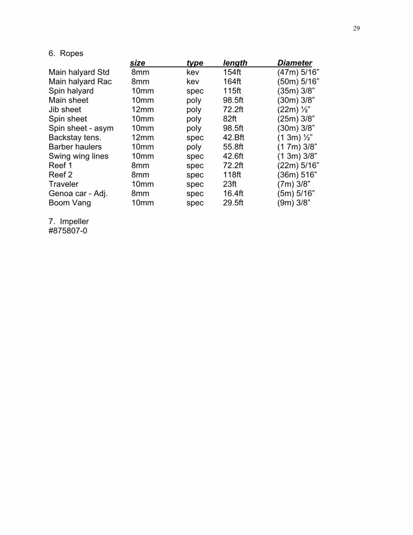
6. Ropes size type length Diameter Main halyard Std 8mm kev 154ft (47m) 5/16” Main halyard Rac 8mm kev 164ft (50m) 5/16” Spin halyard 10mm spec 115ft (35m) 3/8” Main sheet 10mm poly 98.5ft (30m) 3/8” Jib sheet 12mm poly 72.2ft (22m) ½” Spin sheet 10mm poly 82ft (25m) 3/8” Spin sheet - asym 10mm poly 98.5ft (30m) 3/8” Backstay tens. 12mm spec 42.Bft (1 3m) ½” Barber haulers 10mm poly 55.8ft (1 7m) 3/8” Swing wing lines 10mm spec 42.6ft (1 3m) 3/8” Reef 1 8mm spec 72.2ft (22m) 5/16” Reef 2 8mm spec 118ft (36m) 516” Traveler 10mm spec 23ft (7m) 3/8” Genoa car - Adj. 8mm spec 16.4ft (5m) 5/16” Boom Vang 10mm spec 29.5ft (9m) 3/8” 7. Impeller #875807-0

30
Extras on DFIOOO Hull #17 VC-17 bottom paint Refrigerator 12V Isotherm Heating Unit - Wallas 3000 - Diesel (Furnace) ARDIC 4 gal Hot water heater Stern Pulpit (with ladder) Anchor fitting with rollers Cockpit Dodger (New) - Full enclosure Zip Sleeve jib cover Shower w/ curtain & sump pump Shore power - 15 amp, cable & charger Holding Tank system Fuel Gauge Water Gauge Bowsprit/Stainless steel & teak ST50 Plus Wind System ST50 Plus Speed System ST50 Depth System ST50 Plus Multirepeater ST50 Plus GPS System ST 4000w Autopilot ST 4000 Remote Control Solar Vent in head Shower on transom w/ Y valve Solar Panels (2) 50Waft Pioneer 12 changer CD Player, Radio Cabin Speakers Cockpit Speakers Cradle for Winter Storage Canvas Cover for Winter Storage Roller Furler for Bowsprit Screecher (Light Wind Sail) VHF - Shipmate 8300 Lightning Grounding strap Leather Upgrade Upgraded fabric