drafts in document despatch advice wide circulationbis.org.in/sf/mhd/mhd12_(0332).pdf ·...
TRANSCRIPT

DRAFTS IN WIDE CIRCULATION TECHNICAL COMMITTEE: MHD 12 ADDRESSED TO: 1. All members of Hospital Equipment, Sectional Committee, MHD 12 2. All Members of Medical Equipment and Hospital Planning Division Council (MHDC) 3. All others interested Dear Madam(s)/Sir(s), Please find enclosed the following documents: Doc No.: MHD 12(0331)/ISO 11135-1:2007 TITLE: Sterilization of health care products —Ethylene oxide — Part 1: Requirements for
development, validation and routine control of a sterilization process for medical devices Doc No.: MHD 12(0332)/ ISO/TS 11135-2:2008 TITLE: Sterilization of health care products —Ethylene oxide — Part 2: Guidance on the application
of ISO 11135-1 Doc No.: MHD 12(0333)/ISO 11138-1:2006 TITLE: Sterilization of health care products —Biological indicators — Part 1: General requirements Doc No.: MHD 12(0334)/ISO 11138-2:2006 TITLE: Sterilization of health care products —Biological indicators — Part 2: Biological indicators
or ethylene oxide sterilization processes Doc No.: MHD 12(0335)/ISO 11138-3:2006 TITLE: Sterilization of health care products —Biological indicators — Part 3: Biological indicators
for moist heat sterilization processes Doc No.: MHD 12(0336)/ISO 11138-4:2006 TITLE: Sterilization of health care products —Biological indicators — Part 4: Biological indicators
for dry heat sterilization processes Doc No.: MHD 12(0337)/ISO 11138-5:2006 TITLE: Sterilization of health care products —Biological indicators — Part 5: Biological indicators
for low-temperature steam and formaldehyde sterilization processes
DOCUMENT DESPATCH ADVICE Ref Date
MHD 12/T- 64, 65, 66, 67, 68, 69 & 70 26-03-2014

Kindly examine these draft standards and forward your views stating any difficulties, which you are likely to experience in your business or profession, if these are finally adopted as National Standard. Last date for comments: 25-6-2014 Comments if any, may please be made in the format indicated and mailed to the undersigned at the above address. In case no comments are received or comments received are of editorial nature, you will kindly permit us to presume your approval for the above document as finalized. However, in case comments of technical nature are received then it may be finalized either in consultation with the Chairman, Sectional Committee or referred to the Sectional committee for further necessary action if so desired by the Chairman, Sectional Committee. Thanking you, Yours sincerely, (S Kishore Kumar) Scientist ‘F’ & Head (MHD) Encl: As above email:1) [email protected] 2) [email protected] Telefax: 011-23230910

FORMAT FOR SENDING COMMENTS ON BIS DOCUMENTS
(Please use A4 size sheet of paper only and type within fields indicated. Comments on each clauses/sub-clauses/table/fig. etc be started on a fresh box. Information in Column 4 should include reasons for the comments and suggestions for modified wording of the clauses when the existing text is found not acceptable. Adherence to this format facilitates Secretariat’s work) Doc No.: MHD 12(0332)/ ISO/TS 11135-2:2008 TITLE: Sterilization of health care products —Ethylene oxide — Part 2: Guidance On the application of ISO 11135-1’ LAST DATE OF COMMENTS: 25-06-2014 NAME OF THE COMMENTATOR/ORGANIZATION: _____________________________________________________________________ Sl. No.
Clause/Sub-clause/
para/table/fig. No. commented
Commentator/ Organization/ Abbreviation
Type of Comments (General/Editorial/
Technical)
Justification Proposed change
Doc: MHD 12 (0332) /ISO/TS 11135-2:2008
FOR BIS USE O
NLY

Draft for Comments only (Not to be reproduced without permission of BIS or used as standard) Last date of receipt of comments is 25-6-2014
Doc No.: MHD 12(0332) ISO/TS 11135-2:2008
Draft Indian Standard
STERILIZATION OF HEALTH CARE PRODUCTS —ETHYLENE OXIDE
PART 2: GUIDANCE ON THE APPLICATION OF ISO 11135-2: GUIDANCE ON THE APPLICATION OF ISO 11135-1
ICS
© BIS 2014
B U R E A U O F I N D I A N S T A N D A R D S MANAK BHAWAN, 9 BAHADUR SHAH ZAFAR MARG
NEW DELHI 110002 March 2014 Price Group
Doc: MHD 12 (0332) /ISO/TS 11135-2:2008
FOR BIS USE O
NLY
Hospital Equipment Sectional Committee, MHD 12
NATIONAL FOREWORD
This draft Indian Standard (Part 2) which is identical with ISO/TS 11135-2:2008 ‘Sterilization of health care products —Ethylene oxide — Part 2: Guidance on the application of ISO 11135-1’ issued by the International Organization for Standardization (ISO) will be adopted by the Bureau of Indian Standards on the recommendation of the Hospital Equipment, Sectional Committee and approval of the Medical Equipment and Hospital Planning Division Council.
ISO 11135 consists of the following parts, under the general title Sterilization of health care products — Ethylene oxide:
Part 1: Requirements for development, validation and routine control of a sterilization process for medical devices
Part 2: Guidance on the application of ISO 11135-1
This Technical Specification describes some of the methods that may be employed to achieve the requirements contained in IS/ISO 11135-1. This document is not intended as a checklist for assessing compliance with IS/ISO 11135-1, rather it is intended to promote a uniform understanding and implementation of IS/ISO 11135-1 by providing explanations and possible methods for achieving compliance with specified requirements. It highlights important aspects and provides examples.
This Technical Specification addresses ethylene oxide (EO) sterilization in both the industrial and health care facility settings, and it acknowledges the similarities and differences between the two applications.
Among the similarities are the common need for quality systems, staff training, and proper safety measures. The major differences relate to the unique physical and organizational conditions in health care facilities, and to the initial condition of re-usable devices being presented for sterilization.
Health care facilities differ from medical device manufacturers in the physical design of processing areas, in the equipment used, and in the availability of personnel with adequate levels of training and experience. The primary function of the health care facility is to provide patient care; medical device reprocessing is just one of a myriad of activities that are performed to support that function.
In terms of the initial condition of medical devices, medical device manufacturers generally sterilize large numbers of similar devices that have been produced from virgin material. Health care facilities, on the other hand, must handle and process both new medical devices and re-usable medical devices of different descriptions and with varying levels of bioburden.
i
FOR BIS USE O
NLY
Doc: MHD 12 (0332) /ISO/TS 11135-2:2008

They are therefore faced with the additional challenges of cleaning, evaluating, preparing and packaging a medical device prior to sterilization. In this document, alternative approaches and guidance specific to health care facilities are identified as such.
In general, moist heat sterilization (also known as steam sterilization) is the method of choice for medical devices and supplies that are sterilized in health care facilities. However, EO gas and its mixtures are effective sterilants that are primarily used for heat- and moisture-sensitive medical devices that cannot be steam sterilized.
For ease of reference, the numbering in this technical specification corresponds to that in IS/ISO 11135-1.
The text of the ISO standard has been approved as suitable for publication as Indian Standard without deviations. Certain conventions are, however, not identical to those used in the Indian Standards. Attention is particularly drawn to the following:
a) Wherever the words ‘International Standard’ appears referring to this standard, theyshould be read as ‘Indian Standard’.
b) Comma (,) has been used as a decimal marker while in Indian Standards, the currentpractice is to use a point (.) as the decimal marker.
The following referenced documents are indispensable for the application of this document. For dated references, only the edition cited applies. For undated references, the latest edition of the referenced document (including any amendments) applies.
In this adopted standard, reference appears to certain International Standards for which Indian Standards also exist. The corresponding Indian Standards which are to be substituted in their place are listed below along with their degree of equivalence for the editions indicated:
International Standard
ISO 11135-1:2007 Sterilization of health care products — Ethylene oxide — Part 1: Requirements for development, validation and routine control of a sterilization process for medical devices
Corresponding Indian Standard
IS/ISO 11135-1:2007 [Doc: MHD 12 (0331) Sterilization of health care products — Ethylene oxide — Part 1: Requirements for development, validation and routine control of a sterilization process for medical devices (Under preparation)
ii
Degree of equivalence
Identical
Doc: MHD 12 (0332) /ISO/TS 11135-2:2008
FOR BIS USE O
NLY

International Standard
ISO 11138-2:2006 Sterilization of health care products — Biological indicators — Part 2: Biological indicators for ethylene oxide sterilization processes
ISO 13485:2003 Medical devices — Quality management systems — Requirements for regulatory purposes
Corresponding Indian Standard
IS/ISO 11138-2:2006 [Doc: MHD 12 (0334)] Sterilization of health care products — Biological indicators — Part 2: Biological indicators for ethylene oxide sterilization processes (Under preparation)
IS/ISO 13485:2003 Medical devices — Quality management systems — Requirements for regulatory purposes
Degree of equivalence
Identical
Identical
The technical committee has reviewed the provisions of the following International Standards referred in this adopted standard and has decided that they are acceptable for use in conjunction with this standard:
International Standard Title
ISO 11140-1:2005 Sterilization of health care products — Chemical indicators — Part 1: General requirements
ISO 11737-1 Sterilization of medical devices — Microbiological methods — Part 1: Determination of a population of microorganisms on products
ISO 17664 Sterilization of medical devices — Information to be provided by the manufacturer for the processing of resterilizable medical devices
For the purpose of deciding whether a particular requirement of this standard is complied with, the final value, observed or calculated, expressing the result of a test shall be rounded off in accordance with IS 2:1960 ‘Rules for rounding off numerical values (revised)’. The number of significant places retained in the rounded off value should be the same as that of the specified value in this standard.
iii FOR BIS USE O
NLY
Doc: MHD 12 (0332) /ISO/TS 11135-2:2008

Contents Page
1 Scope ..................................................................................................................................................... 1 2 Normative references ........................................................................................................................... 1 3 Terms and definitions........................................................................................................................... 2 4 Quality management systems ............................................................................................................. 2 4.1 Documentation...................................................................................................................................... 2 4.2 Management responsibility ................................................................................................................. 2 4.3 Product realization................................................................................................................................ 3 4.4 Measurement, analysis and improvement — Control of non-conforming product ....................... 3 5 Sterilizing agent characterization ....................................................................................................... 3 5.1 Sterilizing agent .................................................................................................................................... 3 5.2 Microbicidal effectiveness ................................................................................................................... 3 5.3 Materials effects.................................................................................................................................... 3 5.4 Environmental considerations ............................................................................................................ 3 6 Process and equipment characterization .......................................................................................... 4 6.1 Process characterization ..................................................................................................................... 4 6.2 Equipment characterization................................................................................................................. 4 7 Product definition ................................................................................................................................. 5 7.1 General................................................................................................................................................... 5 7.2 Product safety and performance......................................................................................................... 8 7.3 Microbiological quality......................................................................................................................... 9 7.4 Documentation...................................................................................................................................... 9 8 Process definition................................................................................................................................. 9 9 Validation............................................................................................................................................. 12 9.1 Installation qualification..................................................................................................................... 13 9.2 Operational qualification.................................................................................................................... 14 9.3 Performance qualification.................................................................................................................. 15 9.4 Varying load configurations .............................................................................................................. 19 9.5 Review and approval of validation.................................................................................................... 19 10 Routine monitoring and control ........................................................................................................ 20 10.1 General................................................................................................................................................. 20 10.2 Parametric release .............................................................................................................................. 21 11 Product release from sterilization..................................................................................................... 22 12 Maintaining process effectiveness ................................................................................................... 23 12.1 General................................................................................................................................................. 23 12.2 Maintenance of equipment ................................................................................................................ 23 12.3 Requalification .................................................................................................................................... 24 12.4 Assessment of change....................................................................................................................... 25 Annex A (informative) Guidance on ISO 11135-1:2007 Annex A Determination of process
lethality — Biological indicator/bioburden approach ..................................................................... 26 Annex B (informative) Guidance on ISO 11135-1:2007 Annex B Conservative determination of
lethal rate of the sterilization process — Overkill approach.......................................................... 36 Bibliography ..................................................................................................................................................... 38
Doc: MHD 12 (0332) /ISO/TS 11135-2:2008
FOR BIS USE O
NLY

1
Sterilization of health care products — Ethylene oxide —
Part 2: Guidance on the application of ISO 11135-1
1 Scope
This Technical Specification provides guidance for the requirements in ISO 11135-1:2007. It does not repeat the requirements and is not intended to be used in isolation.
The exclusions in ISO 11135-1 apply also to this Technical Specification.
For ease of reference, the clause numbering in this Technical Specification corresponds to that in ISO 11135-1:2007. Further guidance for the requirements given in ISO 11135-1 is also included in Annex C of ISO 11135-1:2007 and should be used in conjunction with this Technical Specification.
This guidance document is intended for people who have a basic knowledge of the principles of EO sterilization but may need help in determining how to best meet the requirements contained in ISO 11135-1. This document is not intended for people lacking a basic knowledge of the principles of EO sterilization.
2 Normative references
The following referenced documents are indispensable for the application of this document. For dated references, only the edition cited applies. For undated references, the latest edition of the referenced document (including any amendments) applies.
ISO 11135-1:2007, Sterilization of health care products — Ethylene oxide — Part 1: Requirements for development, validation and routine control of a sterilization process for medical devices
ISO 11138-2:2006, Sterilization of health care products — Biological indicators — Part 2: Biological indicators for ethylene oxide sterilization processes
ISO 11140-1:2005, Sterilization of health care products — Chemical indicators — Part 1: General requirements
ISO 11737-1, Sterilization of medical devices — Microbiological methods — Part 1: Determination of a population of microorganisms on products
ISO 13485:2003, Medical devices — Quality management systems — Requirements for regulatory purposes
ISO 17664, Sterilization of medical devices — Information to be provided by the manufacturer for the processing of resterilizable medical devices
FOR BIS USE O
NLY
Doc: MHD 12 (0332) /ISO/TS 11135-2:2008

2
3 Terms and definitions
For the purposes of this document, the terms and definitions in ISO 11135-1 and the following apply.
3.1 dunnage material used to mimic all or part of a sterilization load
3.2 health care facility set of physical infrastructure elements intended to support the delivery of specific health-related services
3.3 processing group collection of products or product families that can be sterilized in the same EO sterilization process
NOTE All products within the group have been determined to present an equal or lesser challenge to the sterilization process than the challenge device for that group.
3.4 EO product family collection of products that are determined to be similar or equivalent for validation purposes
3.5 re-usable medical device medical device designated or intended by the manufacturer as suitable for reprocessing and re-use
NOTE This is not a medical device that is designated or intended by the manufacturer for single use only.
3.6 single use medical device medical device that is designated or intended by the manufacturer for one-time use only
3.7 sterilization specialist person with knowledge of the sterilization technology being utilized and its effects upon materials and microorganisms
NOTE This level of knowledge has been obtained by both practical and theoretical means and the person does not require guidance on the basic principles of the technology involved.
4 Quality management systems
4.1 Documentation
4.1.1 No guidance offered.
4.1.2 No guidance offered.
4.2 Management responsibility
4.2.1 Each organization should establish procedures for identifying training needs and ensure that all personnel are trained to adequately perform their assigned responsibilities.
4.2.2 No guidance offered.
Doc: MHD 12 (0332) /ISO/TS 11135-2:2008
FOR BIS USE O
NLY

3
4.3 Product realization
4.3.1 Purchasing procedures in a health care facility should ensure that re-usable medical devices are supplied with validated instructions for cleaning, disinfection, sterilization and aeration as specified in ISO 17664.
4.3.2 For those facilities that do not fully comply with ISO 13485, such as health care facilities, procedures for identification of product and maintenance of traceability, should include the labelling of each item or package prior to sterilization with a lot control identifier that includes the following information:
a) the sterilizer ID or code;
b) the date of sterilization;
c) the cycle number (i.e. the cycle run of the day or sterilizer).
It is recommended that the identity of the person who assembled the pack also be included on the identifier, to allow for further investigation if a problem should arise.
Lot identification information enables personnel to retrieve items in the event of a recall and to trace problems to their source.
4.3.3 No guidance offered.
4.4 Measurement, analysis and improvement — Control of non-conforming product
No guidance offered.
5 Sterilizing agent characterization
5.1 Sterilizing agent
EO is a highly penetrative gas that will permeate most packaging materials and polymeric materials. Widely recognized compositions include 100 % EO and blends with carbon dioxide or nitrogen. The storage conditions for EO should be in accordance with the EO manufacturer’s recommendations and all applicable regulations.
5.2 Microbicidal effectiveness
No guidance offered.
5.3 Materials effects
No guidance offered.
5.4 Environmental considerations
5.4.1 EO is toxic, flammable and explosive; therefore, extreme caution should be used during its storage, handling and use.
5.4.2 Effluent gas should be discharged through an EO-gas treatment system, such as a catalytic oxidiser, wet acid scrubber or thermal oxidiser.
When choosing a diluent, its ozone depleting potential should be taken into consideration.
FOR BIS USE O
NLY
Doc: MHD 12 (0332) /ISO/TS 11135-2:2008

4
6 Process and equipment characterization
In health care facilities, process and equipment characterization are generally the responsibility of the sterilizer manufacturer. The management of the health care facility should have controls in place to ensure that its equipment purchases conform to national, regional and local regulations and are suitable for the products intended to be sterilized. The management of the health care facility should ensure the facility has the infrastructure necessary to operate the sterilizing equipment and to achieve sterilization of medical devices.
6.1 Process characterization
No guidance offered.
6.2 Equipment characterization
6.2.1 The following factors should be considered when characterizing the equipment.
Preconditioning equipment characterization
Preconditioning may be performed in a separate preconditioning area (chamber, cell or room). The preconditioning area (if used) should have the following performance and monitoring capabilities:
⎯ air circulation system: adequate air circulation to ensure the uniformity of temperature and humidity in the usable space, and to ensure that uniformity is maintained in a fully loaded room or chamber;
⎯ airflow detection equipment, alarm systems or indicators monitoring the circulation system to ensure conformance to predetermined tolerances;
⎯ means of monitoring temperature and humidity;
⎯ means of controlling temperature and humidity;
NOTE Temperature and humidity sensor control systems may utilize redundant sensors for temperature and humidity determination in the room.
⎯ a time clock or other means of recording time of load entry into and removal from the preconditioning area, if applicable.
Sterilization chamber equipment characterization
The sterilization chamber should have the following performance and monitoring capabilities:
⎯ means of monitoring chamber pressure, temperature and humidity (if humidity additions are controlled by sensor readings);
⎯ means of controlling chamber pressure, temperature and humidity, if humidity additions are controlled by sensor readings [when sensors are fixed on the equipment, ensure that a correlation is made during installation qualification (IQ) or operational qualification (OQ) at the coldest location];
⎯ if parametric release is used, instrumentation for the direct analysis of humidity during conditioning and EO concentration during sterilant exposure time;
⎯ a system controlling that gaseous EO was admitted to the chamber. This can be done by measuring the temperature of the EO gas flowing from the vaporizer to the sterilizer chamber or monitoring the pressure rise during EO injection. This system may control EO concentration during sterilant exposure time.
Doc: MHD 12 (0332) /ISO/TS 11135-2:2008
FOR BIS USE O
NLY

5
Aeration equipment characterization
An aeration area (chamber, cell or room) may be used to remove EO residuals from product/packaging. Temperature uniformity, fresh air make-up and air re-circulation throughout the area are important to ensure consistent and reproducible results. The aeration area should have the following:
⎯ airflow detection equipment, alarm systems or indicators monitoring the air handling system to ensure that it operates within specified parameters and maintains adequate airflow in a fully loaded room or chamber;
⎯ equipment to re-circulate air;
⎯ means of monitoring room temperature;
⎯ means of controlling room temperature.
Prior to removing product from a sterilizer, precautions should be taken to ensure that operators are not exposed to high levels of EO due to the outgassing of the load.
The equipment specification should be reviewed to ensure that regulatory and safety requirements are met, technical specifications are appropriate, and services and infrastructure necessary to operate the equipment are available.
6.2.2 Humidification by steam injection is required in ISO 11135-1, because humidifiers that operate by dispersion of unheated water as an aerosol (e.g. spinning disc humidifiers and nebulizers) can be potent sources of microbial contamination.
6.2.3 No guidance offered.
6.2.4 If there is an undetected failure of a control or monitoring function, a sterilization load could be released without having met its required processing parameters. To prevent this from happening, it is general practice to have redundant sensors for many critical process parameters. The common options for utilizing these redundant sensors include:
a) use one sensor for control, and another sensor for monitoring and reporting;
b) use two sensors, or their average value, for both monitoring and control; this system needs to generatean automatic fault condition if the difference between the two sensors exceeds a defined value;
c) use dual element sensors for both monitoring and control; this system needs to generate an automaticfault condition if the difference between the two elements exceeds a defined value.
7 Product definition
7.1 General
Product definition involves documentation of essential information about the medical device to be sterilized (i.e. the new or modified product).
7.1.1 Product definition for a medical device includes the medical device itself, the primary package containing the device, and any accessories, instructions, or other items included in the primary package. It also includes a description of the intended functionality of the medical device, and the available manufacturing and sterilization processes. The product definition process should also consider whether this is a new design, or whether it is part of an existing EO product family.
The following should be considered as part of product definition:
a) physical description of the medical device (composition and configuration);
b) intended use of the medical device;
FOR BIS USE O
NLY
Doc: MHD 12 (0332) /ISO/TS 11135-2:2008

6
c) whether the medical device is intended for single use or for multiple use;
d) design characteristics that would affect the choice of sterilization process (e.g. batteries, fibre-optics,computer chips);
e) raw materials/manufacturing conditions that could affect microbiological quality (e.g. materials of naturalorigin);
f) required sterility assurance level (SAL);
g) packaging;
h) loading pattern; requirements for a specific load or mixed loading patterns, or range of acceptable loadingpatterns;
i) compatibility with the sterilant gas or gas mixture and EO processing conditions (preconditioning,sterilization and aeration processes).
7.1.2 A technical review should be performed to compare the new or modified product to the validated product and/or process challenge device (PCD) that was used to validate the existing EO process. The construction and configuration of the new or modified product should be carefully examined for any features that could present obstacles to the penetration of EO, heat or humidity. For medical device manufacturers, this comparison should also involve an examination of factors that could affect the initial bioburden on the product, including the location of the manufacturing facilities, the types of raw material used, the sources of these materials and production methods. For new re-usable products, this comparison should include the evaluation of the cleaning efficacy for this product.
If a new or modified product is demonstrated to be equivalent to an existing medical device or PCD for which sterilization characteristics are already known, the new or modified product might be considered to be part of an EO product family or a processing group.
NOTE AAMI TIR28[10] is a useful guide for minimizing the risk of introducing a new or modified product that presents a greater challenge to the sterilization cycle than was previously validated.
As part of the technical review the following questions should be considered. If the answer to any of the following questions is “yes,” further evaluation of the new or modified product might be necessary to determine if it is more difficult to sterilize than the previously validated product:
a) With respect to the previously validated product, does the new or modified product:
1) have more restricted passageways or inner chambers;
2) have fewer openings;
3) have more internal surfaces;
4) have more mated surfaces;
5) have more closures;
6) have longer or narrower lumens;
7) include changes or differences that could reduce the transfer of heat, moisture or sterilant gas;
8) have a bioburden number or resistance significantly higher than that of the reference product (due tomanufacturing conditions, handling, cleaning process or materials used) or
9) contain materials or structures that could be adversely affected by the proposed processing orsterilization method?
Doc: MHD 12 (0332) /ISO/TS 11135-2:2008
FOR BIS USE O
NLY
7
b) With respect to the previously validated product, does the packaging of the new or modified product:
1) have any changes in packaging elements, including instructions or protective barriers;
2) have any additional impermeable protective barriers, e.g. container, case, template, that wouldrestrict or interfere with sterilant or humidity penetration or removal;
3) have a change in the porosity of the packaging material (e.g. basis weight, coating, treatment –adhesive or coating on paper);
4) have a decrease in the surface area of the venting material or underlying opening, e.g. application oftape or secondary label, change in size of label;
5) increase the bioburden level of the product or
6) change the number of barrier layers?
c) With respect to the previously validated product, does the load configuration of the new or modifiedproduct:
1) differ significantly from the validated load configuration of the reference load;
2) differ significantly in the amount of absorptive materials;
3) differ significantly in density from that of the reference load or
4) differ significantly in total load volume?
7.1.3 No guidance offered.
7.1.4 No guidance offered.
7.1.5 A means of demonstrating equivalence is the comparison of the relative rates of inactivation of BIs placed in the most difficult-to-sterilize location within the new or modified product and previously validated product when both are exposed to a fractional cycle.
A PCD is a device or test pack into which a microbiological challenge is located. Examples of ways to develop PCDs for use in the demonstration of equivalence include, but are not limited to:
a) placement of a microbiological challenge between rings, lands, grommets or ribs of a syringe stopper;
b) placement of a microbiological challenge in the middle of the lumen of a tube that is then reconnectedusing a solvent bond agent or a connector to restore product integrity;
c) placement of a microbiological challenge in an interface;
d) placement of a microbiological challenge in a series of envelopes or packages.
Several PCD designs have been recommended for use in health care facilities.
NOTE 1 For further information see EN 1422[13], ANSI/AAMI ST41[11] and AS/NZS 4187[12].
To prepare the PCD, the microbiological challenge can be inoculated on the product either directly or indirectly. Direct inoculation is accomplished by applying a liquid suspension of the spores on the product. Indirect inoculation is accomplished by placing an inoculated carrier either within the package or in/on the product.
FOR BIS USE O
NLY
Doc: MHD 12 (0332) /ISO/TS 11135-2:2008

8
Listed below are various ways to prepare a PCD.
⎯ Inoculated product: the product to be sterilized is used to prepare the PCD and is inoculated directly or indirectly.
⎯ Inoculated simulated product: a simulated product is used to prepare the PCD and is inoculated directly or indirectly. The simulated product consists of portions of a medical device or a combination of components that are known to represent the greatest challenge to the process while still adequately representing all products within an EO product family.
⎯ Inoculated carrier: a carrier such as a paper strip, disc or other substrate is used to prepare the PCD and is directly inoculated. The resistance of the inoculated carrier should be correlated with the resistance of the inoculated product, simulated product or natural product to use the inoculated carrier for the determination of process lethality.
NOTE 2 Inoculation with a spore suspension can result in variable resistance of the inoculated product because of surface phenomena, other environmental factors and the occlusion of the spores on or in the product. Therefore, it is important to provide scientific rationale or validation for this practice to ensure that the resistance of the inoculated simulated product is reasonably correlated to the natural product. The inoculum recovery must also be validated if resistance is measured by plate count techniques. See Gillis and Schmidt[14], West[22], and ISO 11737-1 for additional information.
7.2 Product safety and performance
7.2.1 The demonstration that the specified sterilization process does not affect the correct functioning of the product may be accomplished by performing functionality tests, or other appropriate tests, on the medical device and packaging following sterilization. These tests may range from a simple visual inspection to a battery of specialized tests.
Elements that could affect safety, quality or performance include:
a) cycle pressure changes that could affect seal integrity;
b) effects of EO exposure time, temperature, humidity and, if applicable, any inert gases present in theintended sterilization blend;
c) inclusion of new materials known to retain higher EO residuals;
d) packaging characteristics;
e) the presence of lubricants, especially within mated surface areas;
f) whether the medical device requires disassembly or cleaning;
g) safety hazards (e.g. leachable materials, or batteries or sealed liquids that could leak or explode);
h) number of sterilization cycles.
Medical devices containing a potential source of ignition (e.g. a battery) should be sterilized using a process that does not contain an explosive mixture of EO in any part of the cycle.
7.2.2 When multiple sterilization cycles are permitted, the evaluation of the product should include biological safety.
For re-usable medical devices, the manufacturer’s reprocessing instructions should be available and followed. The instructions should include the recommended sterilization parameters and the limits to the number of sterilization cycles. If applicable, testing and inspection should be performed to assess functionality of the re-usable medical device following sterilization. The medical device manufacturer’s claims for the number of allowable cycles should be considered to be the maximum. A system should be in place which will provide notification if the maximum number of cycles is reached.
NOTE See ISO 17664 for more information.
Doc: MHD 12 (0332) /ISO/TS 11135-2:2008
FOR BIS USE O
NLY

9
7.2.3 No guidance offered.
7.2.4 Proper aeration is essential to control EO residues in medical devices after EO processing. If information regarding aeration time for a medical device is not available from the manufacturer, the health care facility should establish the aeration time for that device. Using either data or knowledge of the product and its material and design, the aeration time should be established based upon the most difficult-to-aerate product or medical device. It is not feasible to test residues on each individual item that has been sterilized.
NOTE See ISO 10993-7[1] for more information.
7.3 Microbiological quality
7.3.1 No guidance offered.
7.3.2 In health care facilities, attention to microbiological quality will comprise having strict procedures for collection and handling of used, re-usable medical devices, and for validation and control of the cleaning processes for re-usable medical devices in accordance with the medical device manufacturer’s instructions.
NOTE See ISO 17664 and the ISO 15883[5],[6],[7],[8] series of documents for more information.
7.4 Documentation
Upon completion of the product definition the following should be documented.
a) The sterilization specification for the product. This specification should fully describe the productconfiguration and how it is to be presented to the EO process (packaging and load configuration). Thespecification should also include or reference the required SAL, as well as evidence for, or assessment of,the compatibility of the product with the process.
b) The result of the comparison between the new or modified product and the existing validated product(s).This result should clearly demonstrate that product complexity, materials, packaging and loadconfiguration were assessed.
c) Evidence or assessment of the bioburden of the product and its resistance relative to the biologicalindicator (BI).
d) The documented conclusion that the new or modified product is suitable for adoption into the EO productfamily/processing group specifically referenced in the current validation study to achieve the specifiedSAL. This conclusion should include or reference any results from additional tests performed tosupplement the existing validation study and any further testing performed for confirmation/qualificationfor routine release of product from the existing validated cycle (i.e. residual testing, functional testing).
This documentation should be:
1) approved by the sterilization specialist and other individuals as required by the normal change controlpractices within the organization;
2) retained for at least as long as the medical device is in use, or for at least as long as required byregulatory agencies or facility policies, whichever is longer;
3) retrievable.
8 Process definition
8.1 During process definition, a manufacturer will use microbiological testing and other analytical tools to help establish an appropriate sterilization process for a medical device. For re-usable medical devices that will be reprocessed in the health care facility, the manufacturer is expected to provide validated reprocessing
FOR BIS USE O
NLY
Doc: MHD 12 (0332) /ISO/TS 11135-2:2008
10
instructions, which are based in part on the process definition. It is then the health care facility’s responsibility to review this documentation and confirm that it can follow the medical device manufacturer’s instructions using its own equipment and sterilization cycles. The health care facility's purchasing procedures should require that, prior to the purchase of an EO-sterilizable medical device, the reprocessing instructions be evaluated to confirm that the device is compatible with the equipment and sterilization processes that are in use at the facility. See also ISO 17664.
If the medical device or packaging manufacturer supplies instructions for reprocessing that are not specific enough or not appropriate (e.g. an EO process with 100 % EO, where the health care facility uses a blend), the facility should either perform a validation or assess the appropriateness of its own reprocessing method, based on materials effect data and reprocessing instructions for other devices. If the health care facility is not able to validate the product or assess the appropriateness of its own reprocessing method, it should not reprocess the medical device.
8.2 A research sterilizer/developmental chamber is usually a smaller vessel than the production sterilizer, and is used to perform studies to support validation.
Process definition may be performed in a research sterilizer/developmental chamber as long as this equipment has undergone IQ and OQ activities. This does not preclude the confirmation by a performance qualification (PQ) in a production chamber to verify that the cycle achieves satisfactory product in terms of safety, quality and performance.
8.3 The sterilization process parameters to be established may include (see also C.8 of ISO 11135-1:2007):
a) temperature set point and range within the preconditioning room (if used);
b) relative humidity set point and range within the preconditioning room (if used);
c) temperature set point and range within the sterilization chamber;
d) relative humidity set point and range within the sterilization chamber;
e) temperature and relative humidity range within the load;
f) gas concentration set point and range within the sterilization chamber (if gas analysis equipment isavailable on the developmental chamber);
g) gas dwell time;
h) temperature set point and range within the aeration room (if used);
i) air flow parameters;
j) setting for the in-chamber air washes prior to removal of load from the sterilization chamber (if used).
NOTE For reference in the development of sterilization processes, Annexes A and B of ISO 11135-1:2007 provide requirements for determination of cycle lethality.
8.4 No guidance offered.
8.5 No guidance offered.
8.6 A number of approaches may be used for determining the appropriateness of the BI.
a) One approach is to use the rationale that most of the microorganisms found on product are less resistantthan Bacillus atrophaeus. This approach can be used in situations where
1) a BI in accordance with Clause 5 and 9.5 of ISO 11138-2:2006 is used;
Doc: MHD 12 (0332) /ISO/TS 11135-2:2008
FOR BIS USE O
NLY
11
2) the product bioburden is consistent, and is not likely to contain highly resistant microorganisms.
In this approach, the estimation and assessment of the bioburden should be performed inaccordance with ISO 11737-1. Trending data should be available and should demonstrate theconsistency of the bioburden regarding the number and types of organism.
b) Another approach for demonstrating the appropriateness of the BI is to ensure that the BI presents anequal or greater challenge to the sterilization process than that of the bioburden. This can bedemonstrated by a test of sterility of the product and BI, using a fractional cycle. The results of this studyshould provide a means of lethality comparison using survival data from the tests of sterility.
c) A third approach can be applied in cases where the bioburden is considered to present an equal orgreater challenge than the BI being used, based on the number or type of microorganism, or where a BIwith a lower population than required by 9.3 of ISO 11138-2:2006 is used.
In this case, the estimation and assessment of the bioburden should be performed according toISO 11737-1.
The resistance of the bioburden and the biological indicator (BI) should be compared by running cycles atgraded exposure times. The comparison of the resistance can be based on direct enumeration methodsand/or fraction negative methods.
If there is an indication that the challenge posed by the product bioburden exceeds that of the BI (i.e. ifthe BI is not appropriate), one of the following can be used:
1) select a BI having a higher population;
2) the product can be pre-treated before sterilization to reduce the bioburden numbers;
3) the product, the process or both can be evaluated to determine how to reduce the bioburden numberor resistance (e.g. by changing the raw materials or manufacturing process used, by improving themanufacturing environment, or by modifying the product design).
If 1), 2) or 3) is used, it is important to verify the effectiveness of the changes.
Product design may not allow a BI to be positioned in the most difficult-to-sterilize location of the product. In this circumstance it may be appropriate to place the BI in a location to which the relationship with the most difficult-to-sterilize location can be established. Additionally, in many medical devices the most difficult-to-sterilize location contains a low number of microorganisms, and therefore the challenge population may be more closely linked to the bioburden of the product.
Different types of PCDs are described in 7.1.5. Methods similar to those used for determining the appropriateness of the BI can be used for determining the appropriateness of the PCD. A PCD located within the product or its load to be sterilized is often referred to as an internal PCD, whereas a PCD located within the carton or case, between the cartons/cases on the exterior surface of the load, or on the exterior case surface or the frame that supports the load, is referred to as an external PCD. External PCDs are generally used to ease access and removal during routine production sterilization.
Studies conducted in a developmental chamber may be used to demonstrate the comparative resistance of the PCDs under consideration; however, the effects of the specific production sterilizer and load to be validated should be assessed. Often the effects of the load volume, density, heat transfer and gas re-circulation cannot be properly duplicated in a developmental chamber. Therefore, it may be necessary to demonstrate the appropriateness of the PCD used to validate and/or monitor the routine production sterilization process in the production sterilizer.
FOR BIS USE O
NLY
Doc: MHD 12 (0332) /ISO/TS 11135-2:2008

12
The comparative resistance of internal versus external PCDs can be assessed using concurrent exposure(s) in a fractional cycle(s). The resulting data can be used for:
⎯ making decisions about which PCD is appropriate to validate a sterilization process;
⎯ evaluating candidate designs for external PCDs (i.e. for routine monitoring of the process);
⎯ assessing the equivalence of new or modified products for adoption into a validated sterilization process;
⎯ deciding if a new or modified product or PCD should become the master product for an EO product family.
There may be instances when it is desirable to compare the resistance of one PCD to another without comparing both to the resistance of the product. This is typically used when an internal PCD has been proven to be appropriate and an external PCD is being introduced. In this case, a method of demonstrating the appropriateness of the PCD is to demonstrate that the external PCD has equal or greater resistance when compared to the internal PCD. If the relative resistance of the external PCD is less than the relative resistance of the internal PCD (not more than 20 %), the PCDs may be considered equivalent.
NOTE It is not uncommon to find an external PCD in a less difficult-to-sterilize configuration having a greater resistance than an internal PCD in a more difficult-to-sterilize configuration. It is theorized that this occurs because the EO is removed more rapidly from the external PCD than the internal PCD, resulting in less gas exposure time to the microbiological challenge.
8.7 No guidance offered.
8.8 No guidance offered.
8.9 No guidance offered.
9 Validation
The object of validation is to document the evidence required to provide a high degree of assurance that a specific process will consistently produce a product meeting the required sterility assurance level. Product sterilized in the validated process should be shown to meet predetermined specifications and quality characteristics related to product functionality and safety (i.e. through product compatibility studies).
Validation of a process should be performed according to an approved written document (protocol) that contains defined acceptance criteria, prior to initiation of testing. This document should be reviewed by a sterilization specialist(s). The elements of validation, as defined in this clause, are:
⎯ IQ;
⎯ OQ;
⎯ PQ.
In a health care facility, IQ and OQ are typically performed by the sterilizer manufacturer, although they may be performed by any qualified personnel. Microbiological PQ data might be available from the sterilizer manufacturer for general loads.
For health care facilities, this means describing and documenting the following:
a) the validation steps that need to be performed;
b) the way in which these validation steps will be performed, along with a listing of responsible individuals,departments and/or outside contractors;
c) the criteria for successful validation.
Doc: MHD 12 (0332) /ISO/TS 11135-2:2008
FOR BIS USE O
NLY

13
For health care facilities, there is an option of contracting with an outside service to perform this validation; however, the health care facility is still responsible for ensuring that the validation complies with the requirements of ISO 11135-1.
9.1 Installation qualification
9.1.1 The following are examples of equipment components that should be qualified to ensure that the equipment was installed according to the applicable specifications and requirements:
a) chamber and door construction (i.e. air tightness and maintenance of uniform temperature);
b) seals and connections on chamber and piping construction (i.e. ability to maintain specified pressure andvacuum extremes);
c) the calibration of instruments (e.g. sensors, recorders, gauges and test instruments) that monitor, control,indicate or record parameters such as temperature, humidity, pressure and EO concentration;
d) supply systems for gases and liquids (e.g. air, nitrogen, steam, EO and water), including filters (if used);
e) the electrical supply, which should adequately and consistently supply the power needed for properequipment and instrumentation operation;
f) gas circulation systems, where used;
g) gas injection systems;
h) vacuum systems, including pumps, pump cooling systems and piping;
i) exhaust, emission control and abatement systems;
j) other critical systems that could affect process conditions, such as process automation, safety systems,etc.
The documented procedures for IQ should specify how each element of this qualification is planned, performed and reviewed.
9.1.2 The supporting documentation for IQ should include descriptions of the physical and operational characteristics of the equipment (including ancillary equipment). Examples of relevant documents include design specifications, the original purchase order, user requirements specifications and functional design specifications.
9.1.3 No guidance offered.
9.1.4 No guidance offered.
9.1.5 National and local requirements for occupational health and safety should be consulted as they apply to potential EO exposure.
To protect the health and the safety of personnel, an EO installation should include equipment that detects atmospheric levels of EO or gas mixtures near the sterilizer and anywhere else where potential exposure could occur.
EO safety is achieved and maintained through a combination of factors that include:
⎯ proper design, installation and maintenance of systems and equipment;
⎯ compliance with applicable regulations for occupational health and safety and for environmental protection;
FOR BIS USE O
NLY
Doc: MHD 12 (0332) /ISO/TS 11135-2:2008

14
⎯ development and implementation of policies and procedures that support safe work practices;
⎯ atmospheric monitoring in areas where EO exposure could occur;
⎯ use of personal monitoring devices as appropriate;
⎯ personnel training;
⎯ periodic audits of equipment, personnel and processes to ensure ongoing compliance with design specifications and with the facility’s policies and procedures.
EO sterilization cycles should operate within the non-flammable region throughout the complete sterilization cycle in order to minimize the risk of explosion. Use of a non-flammable sterilizing agent can improve safety by decreasing the risk of fire or explosion. It can also facilitate compliance with country-specific equipment safety requirements. Non-flammable sterilizing agents are produced by mixing the highly flammable EO gas with one or more inert gases. The flammability of such a mixture can be calculated by measuring the relative proportions of EO, air, inert gas (e.g. nitrogen) and water vapour in the sterilizer.
9.1.6 Drawings, process and instrumentation diagrams (P&ID), and schematics should be checked against the as-installed configuration and updated where necessary.
Drawings and parts lists for the equipment should include:
a) pipe work and instrumentation schematic drawings (i.e. process and instrumentation diagrams);
b) a list of other pertinent mechanical and electrical drawings and their location;
c) a list of critical instruments and devices, particularly those influencing process control, for which physicalcharacteristics and manufacturer performance claims (e.g. accuracy, repeatability, size and model)should be kept on file;
d) process control logic or software documentation necessary to support validation, including control systemlayout, control logic diagrams and application software (computerized measurement and control systems)such as program listings, flow charts, ladder logic diagrams where applicable and strategy diagrams.
9.2 Operational qualification
9.2.1 The following information should be documented for all instrumentation used for monitoring, controlling, indicating or recording:
a) equipment identification;
b) calibration schedule;
c) actual completion date for each calibration, as well as who performed it;
d) the next scheduled calibration date.
9.2.2 OQ for EO equipment is carried out either with an empty sterilizer chamber or using appropriate test material to demonstrate the capability of the equipment to deliver the range of operating parameters and operating limits contained in the equipment specification. This range of parameters and operating limits should include the initial sterilization process that has been defined (see Clause 8).
OQ may include the following:
a) temperature distribution test;
b) humidity distribution test;
Doc: MHD 12 (0332) /ISO/TS 11135-2:2008
FOR BIS USE O
NLY

15
c) air circulation test (if used);
d) chamber leak testing;
e) vacuum rates;
f) rates of addition of process gases such as EO, nitrogen, steam and air.
A chamber wall temperature study should be completed. The study should use temperature sensors located in a defined arrangement in the chamber interior close to the walls and doors to verify adequate temperature uniformity provided by the jacket heating system. The study should characterize the temperature profile for comparison on a periodic basis to assure the system continues to operate effectively. Instead of sensors, this can be done using a pyrometer reading on chamber surfaces to reflect surface temperatures.
If the OQ is done with an empty chamber, an empty chamber temperature and humidity distribution test should be completed using temperature and humidity sensors located in a defined arrangement to permit a comparison with the chamber control temperature. Sensors should be evenly distributed and should be located at the middle, top, bottom, front and back of the chamber volume (see Tables C.1 and C.2 of ISO 11135-1:2007 for guidance on the number of sensors). Empty chamber studies are useful to ensure that the installed equipment is capable of delivering the defined process (see Clause 8) within defined tolerances. This study can also be done with product, but it is important that material or products are uniform so that the variation in load configuration and density will not influence the results.
It is recommended that pressure and/or vacuum tests be performed to detect chamber leaks. These tests should be performed in accordance with the sterilizer manufacturer’s instructions and under conditions that are representative of a routine sterilization cycle.
The system software (e.g. computerized measurement and control systems) should be tested in all fault conditions during OQ. The user is responsible for assuring the software is validated. If the software is embedded in the equipment, the manufacturer is responsible for the software validation.
9.3 Performance qualification
9.3.1 General
PQ consists of rigorous microbiological and physical testing, beyond routine monitoring, to demonstrate the efficacy and reproducibility of the sterilization process. PQ is normally not started until after completion and approval of the IQ and OQ testing. Acceptance criteria should include conformance with the specifications for the sterilization process parameters and microbiological challenge.
9.3.1.1 No guidance offered.
9.3.1.2 No guidance offered.
9.3.1.3 The product and load used during validation should be at least as difficult to sterilize as the most challenging load expected during normal production. Changes in the load configuration/pattern can diminish the lethality of a sterilization process. It is important that the acceptable load configurations be specified. If multiple load configurations are allowed, the load configuration used in the validation studies should represent the most difficult-to-sterilize configuration, or should have a known relationship to the most difficult-to-sterilize configuration.
When the load is composed of products, such as surgical kits, that contain a number of different materials (e.g. plastics, metals, cotton, etc.), it is very important to verify the load configuration because these materials do not behave similarly when heated during preconditioning and conditioning. Some of the product components will need additional time to meet the cycle specifications defined.
FOR BIS USE O
NLY
Doc: MHD 12 (0332) /ISO/TS 11135-2:2008

16
During PQ, two types of load may be chosen:
a) dunnage;
b) saleable product.
If the validation load is to be re-used during PQ, the loads should be aerated and re-equilibrated to ambient conditions prior to starting the next run. If equilibration time is insufficient, the load could be warmer than the normal ambient conditions, or the load humidity may be much lower than the normal ambient load conditions. Either of these situations can produce data that are not representative of normal production. Too high a starting temperature can produce an unrealistically rapid kill rate. Too low a humidity can produce an unrealistically low kill rate.
If saleable product is used in validation studies, procedures should be established to ensure the product is subjected to a full exposure sterilization process and formal review of its acceptance prior to release to market.
9.3.1.4 In specifying the presentation of product, both loading pattern (the composition of the load) and the placement of items within the load should be considered.
Typical load parameters to be defined may include stacking configuration, overall density, dimensions, material composition, and use and type of pallet wrap. The loading pattern should be documented for each sterilizer. Reference load(s) may be specified and used for validation purposes.
Product placement should also be specified. In a large industrial sterilizer, this would refer to the positioning of cases in a pallet or tote. In a smaller sterilizer, like one used in a health care facility, this refers to the positioning of baskets, packs and rigid containers on a sterilization carriage or carrier.
9.3.1.5 No guidance offered.
9.3.2 Performance qualification — Microbiological
9.3.2.1 Microbiological PQ (MPQ) is performed by executing the sterilization process with at least one parameter set to a value less than that used in normal production. Parameters that are most often adjusted are the gas exposure time, gas concentration and process temperature. The process parameters chosen for the microbiological portion of PQ should be more challenging (in terms of the likelihood of achieving sterility) than the parameters established for the routine process. For example, the process time, temperature, relative humidity, and/or EO concentrations could be run at setpoints that are at the lower extreme of the normal process range. This would provide assurance that any observed values within the specified range will produce acceptable lethality.
Other parameters may be adjusted as necessary to provide assurance that the validation delivers less lethality than the normal production process. Additionally, it is common practice to shorten the post-exposure phases of the cycle or to remove BIs prior to the aeration phase or after an abbreviated aeration phase. This is done to minimize “residual kill” of the BIs due to EO that is present in the load during the aeration phases of the cycle. When shortening the post-exposure phases of the cycle, factors such as operator safety should be taken into account. If aeration times are reduced in validation studies, care should be taken to ensure operators are not exposed to levels of EO that exceed regulated limits. The parameters selected for MPQ, with the exception of exposure time, should remain fixed throughout MPQ.
9.3.2.2 The microbiological challenge defined in MPQ should be designed to assure the required SAL is attained for all product load combinations. To achieve this objective, it is common to use PCDs or a worst case product to represent EO product families.
9.3.2.3 No guidance offered.
Doc: MHD 12 (0332) /ISO/TS 11135-2:2008
FOR BIS USE O
NLY

17
9.3.2.4
Establishing relationship between developmental chamber and production chamber
If a research vessel/developmental chamber was used for process definition, consideration should be given to establishing the relationship between data from the developmental chamber studies and data from the production chamber. The development of the microbial inactivation curves is not always possible in production chambers because of the size of the chamber and the time required to inject and remove EO in the chamber. These long injection and vacuum times limit the ability to obtain the required fractional recovery of indicator organisms. These inactivation curves may be developed in a developmental chamber that can deliver equivalent parameters used in the production chamber. Methods for demonstrating a relationship between the data developed in the developmental chamber and a production chamber involve a physical profile comparison and load density comparison. The sterilization conditions delivered in the developmental chamber should be compared with the physical profile obtained in a production chamber.
Parameter comparison
It might be possible to establish the relationship between the studies performed in a developmental and production chamber by comparing the following:
a) temperature set point and range within the preconditioning room (if used);
b) relative humidity set point and range within the preconditioning room (if used);
c) preconditioning time;
d) temperature set point and range within the sterilization chamber;
e) relative humidity set point and range within the sterilization chamber;
f) gas concentration set point and range within the sterilization chamber (if gas analysis equipment isavailable on the developmental chamber);
g) gas dwell time;
h) pressure vacuum/transfer depths and rates;
i) microbial lethality;
j) temperature set point and range within the aeration room (if used);
k) temperature and relative humidity range within the load.
The lowest temperature location(s) in the load or the slowest-to-heat locations are generally considered to be the worst-case or most difficult-to-sterilize locations. If these conditions and locations are known for the production chamber, they should be simulated in the developmental chamber.
Comparison requirements can vary because of the specific sterilization cycle and equipment used. The sterilization specialist needs to determine the applicability of data developed in a developmental chamber on a case-by-case basis.
Product/load comparison
If a developmental chamber is used, test samples can be cosmetically defective, but they should be reflective of what will be manufactured and packaged in the routine product/package configuration. Consideration should be given to the use of new shipping containers for the studies, as the case dynamics might be different if the cases have been exposed to EO in previous studies.
FOR BIS USE O
NLY
Doc: MHD 12 (0332) /ISO/TS 11135-2:2008

18
The comparison of developmental and production loads should be based on equivalency of the load, not only in terms of its weight to volume, but also in terms of the challenge that the product and its final shipping configurations, as well as the load configuration, present to the sterilization process.
Duplicating the density and sterilizer volume in a developmental chamber may not reproduce all of the effects on the sterilization process that are created by a production load. The penetration of many layers of a routine production pallet load may affect the delivered lethality. Therefore, it may take longer to attain the same lethality observed in the developmental chamber.
9.3.2.5 If chambers are to be assessed for equivalence, the approach should be defined in a formal protocol or procedure. It might not be possible to document equivalence until a full validation study has been performed in the original chamber. It is more common to use equivalence to reduce the extent of revalidation after validation data and routine production run data have been obtained and analysed. The decision on chamber equivalency requires a formal documented review using professional judgment to determine additional validation requirements. See 12.4 of ISO 11135-1:2007.
9.3.3 Performance qualification — Physical
Results obtained from OQ should be used to identify features needing evaluation during physical PQ.
9.3.3.1 If the microbiological PQ includes three consistent half cycle runs, these may be used to demonstrate reproducibility of the process throughout the load as required in 9.3.3.1 a) of ISO 11135-1:2007. Nevertheless, at least one additional qualification run is required, using the routine process specification, to demonstrate that specified acceptance criteria are met throughout the load as required by 9.3.3.1 b) of ISO 11135-1:2007.
If the microbiological PQ does not include three consistent half cycle runs or uses another validation method, three runs using the routine process specification are necessary to meet the requirements of 9.3.3.1 a) and b) of ISO 11135-1:2007.
If, in any of these runs, sterility or product functionality requirements are not met, or if process parameters cannot be maintained within the defined limits, additional qualification runs are required after appropriate modifications are made. Qualification runs should be carried out with the maximum intended chamber load or with the product mix and load that are determined to be the most difficult to sterilize.
9.3.3.2
a) PQ should be performed with the preconditioning area (if used) loaded to the specified maximum, as wellas in typical partially-loaded states. PQ should be carried out with the loading patterns and palletseparations specified in the documented procedures. For large preconditioning areas where a small loadwill not have a significant effect on the area dynamics, it is not necessary (and indeed may be impractical)to perform the studies with the preconditioning area in various loading states.
PQ of preconditioning (if used) should be conducted using product that is at or below the minimumtemperature specified for product to enter the preconditioning area. If it is anticipated that initial producttemperature could vary, for example because of transport for sterilization at a remote facility, the designof the qualification testing should reflect this possibility.
The guidance on physical PQ of preconditioning also applies to the performance qualification ofconditioning (i.e. during sterilization). The minimum number of sensors should match the number ofsensors in Annex C of ISO 11135-1:2007.
b) No guidance offered.
c) No guidance offered.
d) If parametric product release is used, the EO concentration profile for the entire gas dwell period shouldbe assessed to determine how the gas concentration changes over the period.
Doc: MHD 12 (0332) /ISO/TS 11135-2:2008
FOR BIS USE O
NLY

19
e) No guidance offered.
f) Temperature and humidity sensors should be located within the packaging (i.e. inside a shipper box orwithin the product packaging) that will be placed in the sterilizer. When preconditioning is used, theproduct should be preconditioned within the specified time range. When preconditioning is not used, thetemperature and relative humidity within the load should be within defined limits prior to the end of theconditioning phase of the cycle.
The temperature and humidity profile within the sterilization load should be evaluated during the time thatis required for the sterilization load to attain the minimum predetermined temperature and humidity. Thetemperatures and humidity levels obtained within the sterilization load after the maximum permittedperiod of preconditioning should also be established to confirm that conditions within the load will notexceed the process specifications.
The temperature probes within the sterilization load should be placed in the locations that are most likelyto experience the greatest temperature variation. These locations should take into account hot or coldspots located during OQ. The locations of hot and cold spots within a load can be significantly differentthan the locations in an empty chamber.
During validation, it is important to take into account the relationship between the load temperature andthe chamber temperature in order to assure adequate load temperature in the routine process.
If sensors are used in the sterilization chamber and 100 % EO or potentially flammable sterilant blendsare used, the temperature and humidity sensors should be intrinsically safe, or should be of an explosion-proof design. These sensors should also be functionally compatible with EO and with any diluent gases.
g) No guidance offered.
9.4 Varying load configurations
Varying load configurations are normal in routine sterilization and it may not be feasible to test every single configuration. Therefore, more than one worst case or reference load configuration may need to be established, and/or appropriate PCDs developed to reflect this diversity. Temperature and humidity profiles should be determined for the reference load(s). From practical experience it has been found that an adequate profile is provided by the use of the same number of probes as for the temperature distribution in the empty chamber during OQ.
9.5 Review and approval of validation
9.5.1 No guidance offered.
9.5.2 Any discrepancies observed during the validation process should be documented, and their effect on the results of the validation should be determined and documented.
9.5.3 No guidance offered.
9.5.4 No guidance offered.
9.5.5 Parametric release is an approach to sterile product release wherein product is considered to be sterile if the essential physical processing parameters are in conformance with the specifications established during the validation for the specific product(s) in a defined load. Parametric release is based upon a documented review of processing records rather than the testing of biological indicators or PCDs for sterility. (See 10.2 of ISO 11135-1:2007 for more information.)
NOTE EO sterilizers used in health care facilities might not be adequately equipped to permit parametric release of product.
9.5.6 No guidance offered.
FOR BIS USE O
NLY
Doc: MHD 12 (0332) /ISO/TS 11135-2:2008

20
10 Routine monitoring and control
10.1 General
a) The ambient temperature of products entering the preconditioning area should be at or above theminimum temperature specified during validation (see 9.5 of ISO 11135-1:2007). It may not be necessaryto determine the temperature of product prior to preconditioning where the conditions of storage areknown. If the product has been exposed to extreme temperatures, for example during transport, it may benecessary to store the product prior to preconditioning, to allow the internal temperature and humidity tostabilize within acceptable ranges.
b) The reference position for routine monitoring of temperature and relative humidity during preconditioningshould be correlated to the location at which it is most difficult to achieve the desired conditions. Datafrom this routine monitoring should be reviewed for acceptability before product is released for sterilization.
c) No guidance offered.
d) A forced circulation system is recommended to assure homogeneity of conditions within the sterilizerchamber. The gas circulation system should be equipped with a monitoring device that indicates whencirculation is ineffective. Devices that monitor “power on” to the fan or pump are not sufficient.
e) No guidance offered.
f) No guidance offered.
g) The humidity is typically calculated by measuring pressure changes. (See also AAMI TIR15[9].) Thehumidity in the chamber is typically calculated by measuring the partial pressure of water vapour injectedinto the chamber. The relative humidity value is then determined using the steam tables by a ratio of thepartial pressure to the saturated vapour pressure for the actual cycle process temperature. This willindicate the relative humidity value in the head space of the chamber and will be accurate until load orother reactions impact the actual water vapour content in the head space. For direct monitoring,see 10.2.b).
h) No guidance offered.
i) See AAMI TIR15[9] for more information.
j) No guidance offered.
k) No guidance offered.
l) No guidance offered.
The following guidance is provided for health care facility applications.
1) External chemical indicators in health care facilities.
Sterilizer indicator tape, an indicating label or an indicating printed legend should be affixed to orprinted on each package assembled by the health care facility that is intended for sterilization. Thepurpose of external chemical indicators is to differentiate between processed and non-processeditems. They do not establish whether the parameters for sterilization were achieved. Indicatorsshould be of Class 1 specification in accordance with ISO 11140-1.
2) Internal chemical indicators in health care facilities.
An internal chemical indicator may be used within each package to be sterilized. If used, thechemical indicator should be placed in that area of the package considered to be the least accessibleto EO penetration; this may or may not be the centre of the pack. While internal chemical indicators
Doc: MHD 12 (0332) /ISO/TS 11135-2:2008
FOR BIS USE O
NLY

21
do not verify sterility, they allow detection of procedural errors and equipment malfunctions. The use of chemical indicators that respond to all the parameters of the EO process is beneficial.
The internal chemical indicator is retrieved at point-of-use and interpreted by the user. The user should be adequately trained and knowledgeable about the performance characteristics of the indicator in order to make an informed decision based on the result shown.
If the interpretation of the indicator suggests inadequate EO processing, the contents of the package should not be used. The complete unused package, including load identification and the chemical indicator, should be returned to the processing department for appropriate follow up. The results of the physical monitoring, chemical indicators elsewhere in the load, and the biological monitoring, should be reviewed, in order to reach a conclusion as to whether the entire load should be recalled or not. Records of this review should be retained. A single non-responsive or inconclusive indicator should not be considered as evidence that the entire load is non-sterile. Chemical indicators can indicate problems associated with incorrect packaging, incorrect loading of the sterilizer, overloading of the sterilizer chamber, malfunctions of the sterilizer, incomplete delivery of the sterilization parameters, or inadequate preconditioning. The “pass” result of a chemical indicator does not prove that the item where the indicator is placed is sterile.
Indicators should be of Class 3, 4, 5 or 6 specification in accordance with ISO 11140-1:2005.
10.2 Parametric release
Parametric release is a method of releasing product from sterilization as sterile without the use of BIs, relying instead on a demonstration of conformity of the physical processing parameters to all specifications. Therefore, data should be gathered for additional processing parameters such as direct analysis of chamber relative humidity and EO concentration, in order to assure that the sterilization process has met specification.
a) The requirement to measure temperature within the sterilizer from a minimum of two points is establishedin order to ensure that an undetected fault in a temperature sensor does not lead to the inadvertentrelease of an improperly processed load. This requirement can be met with separate recording andmonitoring sensors (see 6.2).
b) Direct analysis of the head space can be performed using electronic sensors, GC, IR or otherspectroscopic methods currently available to indicate water vapour concentration and calculation of therelative humidity value. The benefit of these methods is the real-time indication plus measurementthroughout the exposure phase without the impact of load or reactivity effects. Electronic sensors requireperiodic calibration to offset the effect of exposure to the EO gas and may require replacement afterrepeated exposures due to irreversible deterioration of materials currently utilized as sensing elements.
c) The frequency of analysis required to demonstrate that the minimum gas concentration is maintainedthroughout EO exposure should be established during the validation studies. Monitoring throughout thegas exposure dwell period should also be done as part of the validation, in order to determine how thegas concentration changes over time. The results of this analysis are specific to the product and loadconfiguration being analysed. The analysis performed during the validation study will result indocumented specifications for how often direct analysis should be performed during the cycle. It isrecommended that, at a minimum, direct analysis of gas concentration be performed during the first andlast portions of gas exposure.
Particular attention should be given to the measurement and documentation of humidity during conditioning, and that of gas concentration during exposure. The direct gas concentration measurement using IR, GC, microwave, and other similar technologies is more accurate than using gas weight and pressure to calculate the gas concentration. Therefore, during parametric release, this measurement provides a gas concentration at that position in the chamber throughout the entire exposure phase without any restrictions of reactivity effects or load impact. The reproducibility and accuracy of the results from direct analysis should be determined during validation. Routine cycle analysis should fall within the determined range for the cycle to be acceptable.
FOR BIS USE O
NLY
Doc: MHD 12 (0332) /ISO/TS 11135-2:2008

22
It may be necessary to introduce an equilibration time at the start of the gas dwell phase of the cycle, to allow the chamber concentration to stabilize as the gas is distributed throughout the chamber and penetrates into the void spaces in the load.
NOTE 1 Due to several factors, such as selective adsorption of EO in the load and the volume taken up by load, the values obtained by calculating the concentrations can differ considerably from direct measurement values.
NOTE 2 Health care facilities do not routinely use parametric release.
11 Product release from sterilization
11.1 The criteria for releasing a sterilization load are based on the following:
a) a formal review of the process documentation by a designated individual (or by a validated automatedprocess) to verify and document that the physical cycle variables are within the tolerances defined in thesterilization process specification; formal release of the load from sterilization may require results fromother tests (e.g. EO residuals, endotoxin, physical testing, etc.) before it can enter the distribution chain;
b) no growth of test organisms from any of the processed BIs following incubation. If, however, parametricrelease has been approved and used, product may be released based on compliance with specifiedprocess variables and parameters.
Routine release of a product following sterilization may be based on a review of electronic records in lieu of paper records. Likewise, required signatures may be made electronically. Users of electronic signatures and records should be aware of, and should meet, national and/or international requirements for this type of documentation. The review of processing records and the decision to release should be performed by qualified individuals.
If a process does not fulfil all of the requirements above, the cause should be investigated. If repair or alteration to the equipment is required, the necessary qualification should be performed before this process can be used again.
11.2 If the sterilization process exhibits a non-conformity, 11.2 of 11135-1:2007 requires that the non-conformity be addressed per documented procedures in accordance with 4.2.3 and 8.3 of ISO 13485:2003.
Failure to meet the physical specification or the observation of growth of indicator organism from BIs (if used) should lead to the sterilization load being placed in quarantine and the cause of the failure being investigated. This investigation should be documented and the subsequent handling of product should be in accordance with documented procedures.
If the decision is to reprocess the load, the suitability of the product and packaging for re-sterilization should be established. The effect of repeated exposure to the sterilization process on product functionality and levels of residual EO, and/or reaction products, should be considered. Records of the original sterilization should be traceable from the re-sterilization records.
If the effect of repeated exposure on packaging is not known, product should be repackaged before re-sterilization.
11.3 If saleable product is used in validation studies rather than “dunnage” material, it is important to assess the effect of repeated exposures to the validation/sterilization processes on product functionality, and levels of residual EO and/or reaction products should be considered.
Doc: MHD 12 (0332) /ISO/TS 11135-2:2008
FOR BIS USE O
NLY
23
12 Maintaining process effectiveness
12.1 General
To ensure that the sterilization process continues to deliver the required SAL, it is necessary to evaluate any changes to the product and packaging, the processes and equipment. The use of a comprehensive product and process change control system is recommended.
12.1.1 One parameter commonly monitored to assure the continued ability to sterilize the load is the product bioburden. The bioburden should be monitored periodically. If significant changes are observed in the number and types of microorganisms, their possible effect on the ability to adequately sterilize the load should be evaluated.
In a health care facility, it is recommended that there be a periodic review of the data on the effectiveness of the cleaning/decontamination process, to confirm that the process is still effective and provides adequate bioburden reduction in preparation for the subsequent sterilization process. Decontaminated medical devices should be visually examined for cleanliness prior to terminal sterilization. Medical devices that are not clean should not be sterilized. Procedures should be maintained for the decontamination and maintenance of each medical device based on the manufacturer’s recommendations, the intended use of the device, and the capabilities of the decontamination resources of the facility (see ISO 17664 and the ISO 15883 series).
It is essential for health care facilities to obtain from the manufacturers detailed reprocessing instructions specific to the medical device, e.g. disassembly. Policies and procedures should be in place to ensure that medical devices are decontaminated.
12.1.2 Documented programmes for calibration of the sterilizing and monitoring equipment are necessary to assure that the process continues to deliver product having the required SAL and performance characteristics.
12.2 Maintenance of equipment
12.2.1 In order to be effective, preventive maintenance activities should follow a defined schedule based on the manufacturer’s recommendations and the performance of the equipment. The procedures should be documented, and maintenance personnel should be trained.
Equipment to be maintained and/or calibrated on a routine basis may include, but is not limited to, the following preconditioning, chamber and aeration equipment:
a) gaskets and seals;
b) monitoring gauges;
c) EO monitoring equipment (i.e. environmental and/or chamber);
d) door safety interlocks;
e) safety pressure relief valves or rupture discs;
f) filters (for periodic replacement);
g) volatilizers/vapourizers;
h) chamber jacket re-circulation system;
i) chamber jacket system (for corrosion and insulation);
j) audible and visual alarms;
k) temperature and humidity sensor equipment;
FOR BIS USE O
NLY
Doc: MHD 12 (0332) /ISO/TS 11135-2:2008

24
l) boiler system for steam and heat supply (i.e. steam quality and quantity);
m) evacuation equipment (vacuum pumps);
n) weighing scales;
o) valves;
p) pressure transducers;
q) timers;
r) recorders;
s) circulation systems.
12.2.2 Sterilization equipment that is not calibrated or is not properly maintained can generate an inaccurate record of the process parameters during the sterilization cycle. If these data are used for product release, it could result in loads being released that have not been adequately sterilized.
12.2.3 No guidance offered.
12.2.4 It is necessary to periodically review the maintenance records and to make any adjustments that are indicated by the data.
12.3 Requalification
12.3.1 It is important to formally assess the need for requalification of the sterilization process at defined intervals to ensure that inadvertent process changes have not occurred and to demonstrate that the original validation remains valid. It is common practice to perform an annual validation review of the overall process (preconditioning, sterilization, aeration) performance and engineering changes during the year to ensure that the validation state of the process has been maintained.
The requalification programme should define acceptable ranges and levels of variability in performance that are required to maintain the validity of the original validation from year to year.
12.3.2 Requalification should include a review of the chamber performance and engineering changes that were made during the year to ensure that the results from the original IQ and OQ are still valid. This review should include a review of:
a) the temperature and relative humidity profiles of the preconditioning areas (if used);
b) the annual empty chamber temperature profile;
c) the temperature of the aeration areas (if used).
Additionally, adverse trends in equipment performance, or sterility failures that occur even though process specifications are being met, should be examined to determine whether requalification is warranted.
Based on this review, the sterilization specialist should determine the extent of physical and microbiological requalification required. The review and decision made should be documented. There are three (3) requalification options available as a result of the review:
1) Full Qualification – consisting of physical and microbiological PQ. This may be required in certainsituations, e.g. following a significant change to product/packaging design or configuration (creating anew “worst-case” condition), process design or equipment/services.
2) No physical or microbiological requalification required – In circumstances where no changes havebeen made to product, packaging, equipment/services and process, acceptable chamber
Doc: MHD 12 (0332) /ISO/TS 11135-2:2008
FOR BIS USE O
NLY

25
performance and engineering review, and the routine sterilization process has operated reliably in the intervening period, then professional judgment may be used to justify that no physical or microbiological requalification efforts need be performed before the next review.
3) Reduced microbiological performance qualification – This may be required in certain situations, e.g.to verify continued appropriateness of the BI relative to the product bioburden, or, after a definedinterval, to provide evidence that there has been no inadvertent change since the previous(re)qualification study. This would typically include, minimally, one fractional or half cycle exposureincluding load temperature and humidity measurements. Fractional cycles in a developmentalchamber may also be used to support a revalidation programme.
It is recommended that a reduced microbiological performance qualification study be performed atleast every two years to verify that the documented paperwork review has captured any changes inthe product or sterilization process.
In all of the above cases, it is important to document the decisions taken as well as the rationale for those decisions, and to define the plan for future review of requalification.
12.3.3 A requalification study may be required if a change has been made in materials, manufacturing location or processing method which may impact the product bioburden resistance. The study should demonstrate that product bioburden has not increased to a level or resistance which would invalidate use of the BI or PCD, or compromise achievement of the required SAL.
12.3.4 No guidance offered.
12.3.5 No guidance offered.
12.3.6 No guidance offered.
12.3.7 No guidance offered.
12.3.8 No guidance offered.
12.4 Assessment of change
Requalification may be required to be performed after:
a) major sterilizer repairs (replacing controls, replacing plumbing packages, major rebuilding or installation ofmajor new components);
b) construction, relocation or environmental changes;
c) unexplained sterility failures;
d) changes in EO supply or delivery, diluent or chamber load patterns.
FOR BIS USE O
NLY
Doc: MHD 12 (0332) /ISO/TS 11135-2:2008

26
Annex A (informative)
Guidance on ISO 11135-1:2007 Annex A Determination of process lethality — Biological indicator/bioburden
approach
A.1 General
This annex provides further guidance to information in Annex A of ISO 11135-1:2007, and supplementary guidance to information in Clauses 8 and 9 of this Technical Specification. Since the biological indicator/bioburden approach and the overkill approach use many of the same procedures, some of the text in this annex duplicates text in Annex B.
If the product bioburden is tested at frequent intervals, then a biological indicator/bioburden approach may be used for process definition.
The combined biological indicator/bioburden approach is based on the use of a resistant BI or other PCD with a population that is equal to or greater than that of the bioburden. This method is appropriate when sufficient bioburden data are available from the bioburden monitoring programme to demonstrate that a BI or other PCD with a population of less than 106 can be used.
The relative resistance and population of the BI or PCD should be compared with the resistance and population of the bioburden typically associated with the product. By knowing the bioburden resistance and the relationship of the bioburden resistance to the BI resistance, one can use a BI in the cycle to predict the sterility assurance level that will be achieved for the bioburden. The log reduction achieved for the BI can be used to calculate the sterility assurance level achieved for the bioburden with the most resistance to the sterilization process.
If this is the case, then the Spore Log Reduction (SLR) data developed in a lethality study for the BI can be used to demonstrate the effectiveness of the process for the product. If the data are generated using an enumeration method, then the SLR can also be predicted from the survivor curve data that are generated. The user should be aware that the minimum cycle time derived from this approach is not, by itself, adequate to validate the sterilization process. Demonstration of the ability to maintain process parameters within defined limits during the proposed full cycle is required.
A.2 Procedure
A.2.1 The location within the product at which sterility is most difficult to achieve may include not only those areas that have reduced sterilant penetration, but also those areas that are more likely to have a significant amount of bioburden present. See 7.2 of ISO 14161:2000[3].
Aspects to consider are:
a) the length and inside diameter of lumens, and whether or not the wall of the medical device allowsdiffusion of EO;
b) absorbency of the different parts of both the product and material;
c) weights and densities of items;
d) load configuration, especially for a mixed product load.
Doc: MHD 12 (0332) /ISO/TS 11135-2:2008
FOR BIS USE O
NLY
27
A.2.2 Annex A of ISO 14161:2000 provides additional guidance on the application of the relationship between the BI and the product bioburden in the biological indicator/bioburden approach.
A PCD might be used and, for this method, should be shown to provide a greater challenge to the sterilization process than the product it represents. The resistance of the PCD must be at least that of the natural bioburden located in the most inaccessible portion of the load. See 7.1.5 for information on the development of PCDs and 8.6 for information on determining the appropriateness of the PCD.
A.2.3 No guidance offered.
A.2.4 Obtaining microbial enumeration data, or fractional kill data, requires exposing the microbial challenge to less lethality than is present in the normal production cycle. This is usually accomplished by reducing the exposure time while holding all other parameters either constant at nominal conditions, or at selected minimum acceptable processing conditions. Utilizing the allowed minimum process temperature for the enumeration study assures the required lethality is obtained when operating within the specified temperature range.
The parameters that primarily affect lethality are exposure time, EO concentration, humidity and temperature. If an adjustment of parameters other than exposure time is made, the overall effect to the cycle should be evaluated since the adjustment may not achieve the desired result because the parameters are interrelated. For example, the result of decreasing temperature would actually increase EO concentration if no change is made to the gas pressure.
A.2.5 It is possible to combine the enumeration and fraction negative approaches for determining lethality or D values. The two approaches are based on different calculation methods. Users generally select one method or the other for determining process lethality.
A.2.6 The data obtained from process lethality studies are used to establish the minimum EO gas exposure time required for the sterilization process. If these studies are performed in a research vessel, caution should be taken in directly applying this time to the sterilization process because kill curves (lethality rates or D values/SLRs) are specific to the process parameters, chamber load configuration, and PCD placement within the load used for the study.
A.3 Process lethality determination
It should be noted that to determine the lethality of a sterilization process, the lethality that is imparted during the other phases of the sterilization cycle (e.g. EO injection and removal) may need to be taken into account to achieve linear and accurate survivor curves. Several methods in the published literature address this issue including Mosley[16], Mosley and Gillis[17], Mosley and Gillis[18], Mosley et al.[19], and Rodriguez et al.[21].
A.3.1 Direct enumeration
This method consists of exposing PCDs or BIs to the experimental cycle, removing the challenge and performing viable microbial counts on the samples or challenge indicators. The survivor count may be used in developing a survivor curve and D value. The D value or SLR value is then calculated using an appropriate regression model. See A.3.1.2 of ISO 11135-1:2007.
A.3.1.1 If survivor curve data are used to establish the exposure time, then the time requirement to achieve the maximum survivor value (10−2) can be calculated from confidence limits. In this case, the probability of a positive BI will be significantly reduced, but it can never be zero. For example, if a product were to have a bioburden of up to 100 microorganisms, then an 8 SLR of the BI would result in an SAL of 10−6.
To determine process lethality, several types of calculations are used. These include the calculation of the SLR of the process, the D value of the spores, and the resulting SAL of the sterilization process. The following are explanations of how to perform these calculations.
SLR is a method used to estimate the decrease in the viable count of microorganisms on a medical device or in a load. The value can then be used to estimate times to achieve various sterility assurance levels.
FOR BIS USE O
NLY
Doc: MHD 12 (0332) /ISO/TS 11135-2:2008

28
Use Equation A.1 to calculate the SLR:
0SLR log( ) log( )tN N= − (A.1)
where
SLR is the spore log reduction;
N0 is the initial population (e.g. 2,31 × 10⁶);
Nt is the population at time t (e.g. 36).
Following is a worked example:
⎯ Log N0 = log(2,31 × 10⁶) = 6,364
⎯ Log Nt = log(36) = 1,556
⎯ SLR = 6,364 – 1,556 = 4,808 ≈ 4,8
If the population reduction was the result of a 30 min EO dwell time, then the SLR/minute is:
4,808 0,160 log/min30
=
Based on the above, the EO dwell time for a 12 log reduction would be:
12 75 min0,160
t = =
Calculation of D value from SLR:
Use Equation A.2 to calculate the D value from the SLR:
Time (min) 30 minvalue 6,25 minSLR 4,8
D = = = (A.2)
Calculation of SAL from D value and SLR:
Use Equations A.3, A.4 and A.5 to calculate the SAL from the D value and the SLR:
Assume a sterility assurance level of 10−6 is desired
N0 = 106
Required Nt = 10−6
Required SLR = log(106) − log(10−6) = 6 − (− 6) = 6 + 6 = 12
Time = (D value) × (Required SLR) = 6,25 min × 12 = 75 min
Doc: MHD 12 (0332) /ISO/TS 11135-2:2008
FOR BIS USE O
NLY

29
If the required SAL is 10−3, then the resultant time is:
Required SLR = log(106) − log(10−3) = 6 − (−3) = 9
Time = D value × Required SLR = 6,25 × 9 = 56,25 min
Dwell TimeSLR valueD
= (A.3)
Net Log Drop SLR log(Assumed Initial Population)= − (A.4)
Net Log DropSAL 10−= (A.5)
Following is a worked example:
⎯ Dwell time = 120 min
⎯ D value = 6,25 min
⎯ Assumed initial population = 106
⎯ Log Assumed initial population = 6
120 minTotal SLR 19,2 log drop6,25 min
= =
Net Log Drop 19,2 6 13,2= − =
13,2 13SAL 10 10− −= ≈
A.3.1.2 No guidance offered.
A.3.2 Fraction negative method using Holcomb-Spearman Karber procedure
There are two forms of the Holcomb-Spearman Karber (HSK) procedure. The simplest, mathematically, is the Limited HSK procedure. In practice, this method is much more difficult to implement than the Unlimited HSK method.
The Limited HSK procedure was developed before computers were commonplace, and calculations were performed manually. The Limited HSK procedure requires:
a) all time increments to be the same (e.g. exactly 2 min increments in the exposure time for each run);
b) exactly the same number of valid PCD/BI samples in each run.
These two limitations require the entire series of tests to be rerun if the time increments between runs were not properly selected, or a PCD/BI sample was lost or not suitable for some reason.
The Unlimited HSK procedure has neither of the above limitations, but the calculations are more complex than in the Limited HSK procedure. If the user develops and validates a spreadsheet to perform the calculations for the Unlimited HSK procedure, then there is no reason to use the Limited HSK procedure. When using the Unlimited HSK procedure, if the initial time increments do not result in the required number of fractional growth samples, the user can simply insert another run at a time that should result in the required minimum number of fractional growth samples. If a PCD/BI is lost, or unsuitable for some reason (e.g. dropped), the calculation simply utilizes the valid number of PCDs/BIs. The paper by Shintani et al.[23] provides worked examples to help validate the spreadsheet, and also provides the equations necessary to calculate the upper 95 % confidence limit for the D value.
FOR BIS USE O
NLY
Doc: MHD 12 (0332) /ISO/TS 11135-2:2008
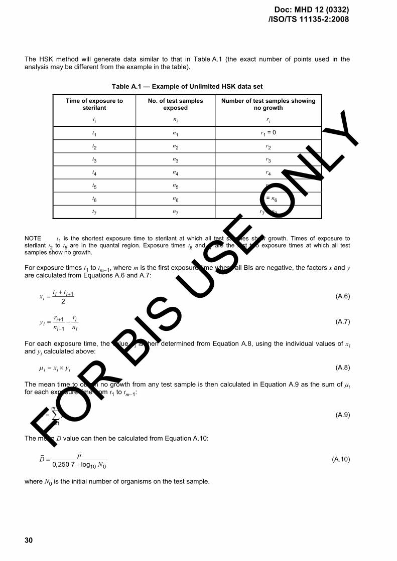
30
The HSK method will generate data similar to that in Table A.1 (the exact number of points used in the analysis may be different from the example in the table).
Table A.1 — Example of Unlimited HSK data set
Time of exposure to sterilant
ti
No. of test samples exposed
ni
Number of test samples showing no growth
ri
t1 n1 r1 = 0
t2 n2 r2
t3 n3 r3
t4 n4 r4
t5 n5 r5
t6 n6 r6 = n6
t7 n7 r7 = n7
NOTE t1 is the shortest exposure time to sterilant at which all test samples show growth. Times of exposure to sterilant t2 to t5 are in the quantal region. Exposure times t6 and t7 are the first two exposure times at which all test samples show no growth.
For exposure times t1 to tm−1, where m is the first exposure time where all BIs are negative, the factors x and y are calculated from Equations A.6 and A.7:
12
i ii
t tx ++= (A.6)
1
1
i ii
i i
r ryn n
+
+= − (A.7)
For each exposure time, the value µi is then determined from Equation A.8, using the individual values of xi and yi calculated above:
i i ix yµ = × (A.8)
The mean time to obtain no growth from any test sample is then calculated in Equation A.9 as the sum of µi for each exposure time from t1 to tm−1:
1
1
m
ii
µ µ−
=
= ∑ (A.9)
The mean D value can then be calculated from Equation A.10:
10 00,250 7 logD
Nµ
=+
(A.10)
where N0 is the initial number of organisms on the test sample.
Doc: MHD 12 (0332) /ISO/TS 11135-2:2008
FOR BIS USE O
NLY

31
For the purposes of calculating the sterilization period using this method, Dcalc, the upper 95 % confidence limit for D should be used. This value is calculated from Equation A.11:
2calcD D V= + (A.11)
where V is calculated from Equations A.12 and A.13:
( ) ( )( )
26
1 1 22
0,251
i i ii i
i ii
r n ra t t
n n+ −
=
⎡ ⎤−⎢ ⎥= − ×⎢ ⎥−⎣ ⎦
∑ (A.12)
( )
2
0
2,302 60,577 22 ln
V aN
⎡ ⎤= ⎢ ⎥
+⎢ ⎥⎣ ⎦(A.13)
NOTE The summation in the determination of “a” is over all the values from i = 2 to the first of the two sequential values where there was no growth. The limit of 6 in Equation A.12 was for illustrative purposes only, assuming 6 data points were obtained up to the first all kill data point.
Table A.2 shows examples of data with non-constant time intervals and non-constant numbers of samples.
Table A.2 — Examples of data with non-constant time intervals and non-constant number of samples
Exposure time to sterilizing agent
ti
Number of test samples exposed
ni
Number of test samples showing no growth
ri
t1 10 n1 20 r1 0
t2 18 n2 19 r2 4
t3 28 n3 21 r3 8
t4 40 n4 20 r4 12
t5 50 n5 20 r5 16
t6 60 n6 20 r6 20
t7 70 n7 20 r7 20
Following is an example of calculations using HSK:
1) Calculate xi and yi (for each exposure).
11
10 18 142 2
i it tx ++ += = =
218 28 23
2x +
= =
328 40 34
2x +
= =
440 50 45
2x +
= =
550 60 55
2x +
= =
FOR BIS USE O
NLY
Doc: MHD 12 (0332) /ISO/TS 11135-2:2008

32
660 70 65
2x +
= =
1 1 11
1 1 1
4 0 0,2119 20
r ryn n
+
+= − = − =
28 4 0,1721 19
y = − =
312 8 0,2220 21
y = − =
416 12 0,220 20
y = − =
520 16 0,220 20
y = − =
620 20 020 20
y = − =
NOTE For the calculations of y4 and y5, both ys = 0,2. This happened because the number of test samples showing no growth increased at a constant rate in this example.
2) Calculate µ for each exposure time, ti:
⎯ µi = xi × yi
⎯ µ1 = x1 y1 = 14 × 0,21 = 2,94
⎯ µ2 = 23 × 0,17 = 3,91
⎯ µ3 = 34 × 0,22 = 7,48
⎯ µ4 = 45 × 0,2 = 9,0
⎯ µ5 = 55 × 0,2 = 11,0
⎯ µ6 = 65 × 0 = 0
3) Calculate the mean time to attain no growth, µ
1 2 3 4 5 6 2,94 3,91 7,48 9,0 11,0 0 34,33µ µ µ µ µ µ µ= + + + + + = + + + + + =
4) Calculate the mean D value,_D
10 00,250 7 logD
Nµ
=+
where N0 = initial population of 1 × 10⁵
Doc: MHD 12 (0332) /ISO/TS 11135-2:2008
FOR BIS USE O
NLY

33
34,33 6,545,250 7
D = =
calc 2D D V= +
0
2,302 60,577 22 ln
V aN
⎛ ⎞= ⎜ ⎟
+⎝ ⎠
( )( )
62
1 1 22
0,251
ii i
i i ii ii
n ra t t rn n
=
+ −=
⎡ ⎤−⎢ ⎥= −⎢ ⎥−⎣ ⎦
∑
5) Calculate the upper 95 % confidence limit for calc( ).D D First find a by performing the abovecalculation for each ti and summing all results:
( ) ( )
( ) ( )
( )
2 2
2 2
2
19 4 21 828 10 4 2,991 7 40 18 8 5,707 0361 18 441 20
20 12 20 160,25 50 28 12 6,113 7 60 40 16 3,368 4400 19 400 1920 2070 50 20 0400 19
a
⎧ ⎫− −⎡ ⎤ ⎡ ⎤− × = + − × = +⎪ ⎪⎢ ⎥ ⎢ ⎥× ×⎣ ⎦ ⎣ ⎦⎪ ⎪− −⎡ ⎤ ⎡ ⎤⎪ ⎪= × − × = + − × = +⎨ ⎬⎢ ⎥ ⎢ ⎥× ×⎣ ⎦ ⎣ ⎦⎪ ⎪−⎡ ⎤⎪ ⎪− × =⎢ ⎥⎪ ⎪×⎣ ⎦⎩ ⎭
0,25 18,180 8 4,545 2a = × =
( )
2
52,302 64,545 2
0,577 22 ln 1 10V
⎡ ⎤⎢ ⎥= ⎢ ⎥+ ×⎢ ⎥⎣ ⎦
22,302 64,545 2
0,577 22 11,513⎛ ⎞
= ⎜ ⎟+⎝ ⎠
( )25,545 2 0,190 45= ×
4,545 2 0,362 7= ×
0,164 9=
calc 2 6,54 2 0,164 9 6,54 2 0,406 1 7,35D D V= + = + = + × =
A.3.3 Fraction negative method using Stumbo Murphy Cochran procedure
The Stumbo Murphy Cochran method utilizes the data from the fraction negative range to calculate a D value. In principle, it can be used with only one run, but data from multiple runs are required to confirm reproducibility. D.3.3 of ISO 11138-1:2006 specifies that data should be obtained from an average of at least three (3) runs in the fraction negative range for the calculation. The D value calculation is relatively straightforward, but calculating the upper 95 % confidence limit is complex, and has several restrictions for the calculation to be valid. The calculation method for the upper 95 % confidence limit on the D value, and the limitations, are presented in the paper by Shintani et al.
FOR BIS USE O
NLY
Doc: MHD 12 (0332) /ISO/TS 11135-2:2008

34
The equation for the Stumbo Murphy Cochran method is:
10 0 10log ( ) log ln
tDnNr
=⎡ ⎤⎛ ⎞− ⎢ ⎥⎜ ⎟
⎝ ⎠⎣ ⎦
(A.14)
where
D is the D value in minutes;
t is the exposure time in minutes;
N0 is the initial population on each BI;
n = total number of BIs in the run;
r = number of BIs negative for growth.
The equation to determine the 95 % confidence interval for the calculated D value is:
1
11,96
rr r nn n n
−± ×
(A.15)
This value is substituted in place of the n/r term in the D value equation above.
Following is a worked example, using a population of 1 × 10⁶, 50 samples/run, and 13 positive samples:
log(106) = 6
Number negative = 50 − 13 = 37
Exposure time = 26 min
( ) ( ) ( )6
26 min 26 26 26 26 3,99 min6 log 0,301 6 ( 0,521) 6,52150 6 log ln 1,351log 10 log ln
37
D = = = = = =− − −⎡ ⎤ ⎡ ⎤−⎛ ⎞ ⎣ ⎦− ⎢ ⎥⎜ ⎟
⎝ ⎠⎣ ⎦
The term for the 95 % confidence interval, which is inserted into the n/r term in the D value equation above, is:
1 1 195%37 1 0,74 0,261 0,74 1,96 0,74 0,74 1,96 0,7437 37 50 50 501,96
50 50 50
CI = = =−
− ± × ± ×± ×
1 1 1 10,74 1,96 (0,062) 0,74 0,1220,74 1,96 0,74 ,052 0,74 1,96 0,003 85
= = = =± × ±± × ±
1 1,160,862
= =
1 1,6180,618
= =
Doc: MHD 12 (0332) /ISO/TS 11135-2:2008
FOR BIS USE O
NLY

35
( )26lower limit 3,81 min
6 log ln 1,16D = =
⎡ ⎤− ⎣ ⎦
26upper limit 4,12 min6 log ln(1,618)
D = =− ⎡ ⎤⎣ ⎦
NOTE The 95 % confidence interval calculations lose accuracy if the value of 1 9.r rnn n
⎛ ⎞× × − <⎜ ⎟
⎝ ⎠
FOR BIS USE O
NLY
Doc: MHD 12 (0332) /ISO/TS 11135-2:2008

36
Annex B (informative)
Guidance on ISO 11135-1:2007 Annex B Conservative determination of lethal rate of the sterilization process —
Overkill approach
B.1 General
This annex provides further guidance to information in Annex B of ISO 11135-1:2007, and supplementary guidance to information in Clauses 8 and 9 of this Technical Specification. Since the biological indicator (BI)/bioburden approach and the overkill approach use many of the same procedures, some of the text in this annex duplicates text in Annex A.
The user should be aware that the minimum cycle time derived from this approach is not, by itself, adequate to validate the sterilization process. Demonstration of the ability to maintain process parameters within defined limits during the proposed full cycle is required.
B.1.1 No guidance offered.
B.1.2
a) Half cycle approach: No guidance offered.
b) Cycle Calculation: This method consists of exposing PCDs or BIs to the experimental cycle, removing thechallenge and performing viable microbial counts on the samples or challenge indicators. The survivorcount may be used in developing a survivor curve and D value. The D value or SLR value is thencalculated using an appropriate regression model. See A.3 in ISO 11135-1:2007.
The sample set exposed at zero time should be exposed to all stages of the experimental cycle prior to sterilant injection.
The enumeration method allows the calculation of a lethality rate with a small number of samples. A minimum of four (4) samples should be used at each of the five (5) exposure times.
B.1.3 A minimum incubation period of 7 d should be used for recovery of BIs unless a reduced incubation study has been completed taking into account the process parameters to be validated.
B.1.4 The appropriateness of the BI relative to the bioburden resistance can be demonstrated by a test of sterility, either before or during process definition using a fractional cycle.
B.2 Procedure
B.2.1 PCDs can be used and, for this method, should be shown to provide a greater challenge to the sterilization process than the product it represents. The resistance of the PCD must be at least that of the natural bioburden located in the most inaccessible portion of the load. See 7.1.5 for information on the development of PCDs and 8.6 for information on determining the appropriateness of the PCD.
B.2.2 The location within the product at which sterility is most difficult to achieve may include not only those areas that have reduced sterilant penetration, but also those areas that are more likely to have a significant amount of bioburden present. See 7.2 of ISO 14161:2000[3].
Doc: MHD 12 (0332) /ISO/TS 11135-2:2008
FOR BIS USE O
NLY

37
Aspects to consider are:
a) the length and inside diameter of lumens, and whether or not the wall of the medical device allowsdiffusion of EO;
b) absorbency of the different parts of both the product and material;
c) weights and densities of items;
d) load configuration, especially for a mixed product load.
B.2.3 Health care considerations: To demonstrate adequate penetration of EO, humidity and temperature into product, a PCD should be chosen for routine monitoring and validation of the EO sterilization process. The resistance of the PCD to EO should be shown to be equal to or greater than the resistance of the natural bioburden of product to be sterilized.
B.2.4 No guidance offered.
B.2.5 Obtaining microbial enumeration data, or fractional kill data, requires exposing the microbial challenge to less lethality than is present in the normal production cycle. This is usually accomplished by reducing the exposure time while holding all other parameters either constant at nominal conditions, or at selected minimum acceptable processing conditions. Utilizing the allowed minimum process temperature for the enumeration study assures the required lethality is obtained when operating within the specified temperature range.
The parameters that primarily affect lethality are exposure time, EO concentration, humidity, and temperature. If an adjustment of parameters other than exposure time is made, the overall effect to the cycle should be evaluated since the adjustment may not achieve the desired result because the parameters are interrelated. For example, the result of decreasing temperature would actually increase EO concentration if no change is made to the gas pressure.
B.2.6 SLRs may be calculated using the results of fractional cycles and the equations and worked examples in Annex A.
Regardless of the method used, it is assumed that:
a) the organism population is homogeneous;
b) the process parameters (except gas exposure time) are constant from run to run;
c) a semi-logarithmic survivor relationship exists;
d) exposed and unexposed organisms respond similarly in the recovery medium.
FOR BIS USE O
NLY
Doc: MHD 12 (0332) /ISO/TS 11135-2:2008

38
Bibliography
[1] ISO 10993-7, Biological evaluation of medical devices — Part 7: Ethylene oxide sterilization residuals
[2] ISO 11138-1:2006, Sterilization of health care products — Biological indicators — Part 1: General requirements
[3] ISO 14161:2000, Sterilization of health care products — Biological indicators — Guidance for the selection, use and interpretation of results
[4] ISO 14937, Sterilization of health care products — General requirements for characterization of a sterilizing agent and the development, validation and routine control of a sterilization process
[5] ISO 15883-1, Washer-disinfectors — Part 1: General requirements, terms and definitions and tests
[6] ISO 15883-2, Washer-disinfectors — Part 2: Requirements and tests for washer-disinfectors employing thermal disinfection for surgical instruments, anaesthetic equipment, bowls, dishes, receivers, utensils, glassware, etc.
[7] ISO 15883-4, Washer-disinfectors — Part 4: Requirements and tests for washer-disinfectors employing chemical disinfection for thermolabile endoscopes
[8] ISO/TS 15883-5, Washer-disinfectors — Part 5: Test soils and methods for demonstrating cleaning efficacy
[9] AAMI TIR15, Ethylene oxide sterilization equipment, process considerations and pertinent calculations
[10] AAMI TIR28:2001, Product adoption and process equivalency for ethylene oxide sterilization
[11] ANSI/AAMI ST41:1999, Ethylene oxide sterilization in health care facilities: Safety and effectiveness
[12] AS/NZS 4187 2003, Cleaning, disinfecting and sterilizing reusable medical and surgical instruments and equipment, and maintenance of associated environments in health care facilities
[13] EN 1422:1997, Sterilizers for medical purposes — Ethylene oxide sterilizers — Requirements and test methods
[14] GILLIS, J. and SCHMIDT, W.C., Scanning electron microscopy of spores on inoculated product surfaces, Medical Device and Diagnostic Industry, 5(6), pp.46-49, 1983
[15] HOLCOMB, R.G. and PFLUG, I.J., The Spearman-Karber method of analyzing quantal assay microbial destruction data, In: Pflug I.J., ed. Selected Papers on the Microbiology and Engineering of Sterilization Processes, 5th ed., Minneapolis: Environmental Sterilization Laboratory, pp.83-100, 1988
[16] MOSLEY, G.A., Estimating the effects of EtO BIER-Vessel Operating Precision on D-value Calculations, Medical Device & Diagnostic Industry, April 2002
[17] MOSLEY, G.A. and GILLIS, J.R., Factors Affecting Tailing in Ethylene Oxide Sterilization. Part 1: When Tailing is an Artifact and Scientific Deficiencies in ISO 11135 and EN 550, PDA Journal of Pharmaceutical Science and Technology, 58, (2) pp.81-95, 2004
[18] MOSLEY, G.A., GILLIS, J.R. and KRUSHEFSKI, G., Evaluating the formulae for integrated lethality in ethylene oxide sterilization using six different endospore forming strains of bacteria, and comparisons of integrated lethality for ethylene oxide and steam systems, PDA J Pharm Sci Technol. 59(1) pp.64-86, 2005
Doc: MHD 12 (0332) /ISO/TS 11135-2:2008
FOR BIS USE O
NLY

© ISO 2008 – All rights reserved 39
[19] MOSLEY, G.A., GILLIS, J.R. and WHITBOURNE, J.E., Formulae for Calculations of Integrated Lethality for EtO Sterilization Processes, Refining the Concepts and Exploring the Applications, Pharm. Tech. 26, (10) pp.114-134, 2002
[20] PFLUG, I.J., Microbiology and Engineering of Sterilization Processes, Minneapolis, Environmental Sterilization Services, 11th ed., Minneapolis, 2003
[21] RODRIGUEZ, A.C., YOUNG, B., CAULK, K., ZELEWSKI, J., DWASNICA, S. and AGUIRRE, S., Calculating Accumulated Lethality and Survivorship in EtO Sterilization Processes, M D & D I, September 2001
[22] WEST, K.L., Ethylene oxide sterilization: A study of resistance relationships, In: Sterilization of Medical Products. Gaughran E. and Kereluk K., eds., Johnson & Johnson, New Brunswick (NJ), 1977
[23] SHINTANI et al., Comparison of D10-value accuracy by the limited Spearman-Karber procedure (LSKP), the Stumbo-Murphy-Cochran procedure (SMCP), and the survival-curve method (EN), Biomed. Instrum. Technol. 29(2), pp.113-24, 1995
[24] STUMBO, C.R., MURPHY, J.R. and COCHRAN, J., Nature of Thermal Death Time Curves for P.A. 3679 and Clostridium Botulinum, Food Technology, 4, pp.321-326, 1950
FOR BIS USE O
NLY
Doc: MHD 12 (0332) /ISO/TS 11135-2:2008