draft work plan - missouri university of science and ...web.mst.edu/~elmoreac/wind turbine/draft...
TRANSCRIPT

Draft Work Plan
Groundwater Remediation Powered by a Renewable Energy Source Former Nebraska Ordnance Plant, Mead, Nebraska Prepared by Fall Semester 2003 Geological Engineering Senior Design Class University of Missouri-Rolla Prepared for U.S. Environmental Protection Agency
November 11, 2003

GEOLOGICAL ENGINEERING 129 McNutt Hall
1870 Miner Circle Rolla, MO 65409-0420 Phone: 573.341.6784 Fax: 573.341.6935 [email protected]
www.umr.edu/~elmoreac
an equal opportunity institution
November 11, 2003
Mr. David Drake, R.G. Remediation Project Manager Region VII 901 North 5th Street Kansas City, KS 66101
Via electronic mail.
Subject: Draft Work Plan, Groundwater Remediation Powered by a Renewable Energy Source, Former Nebraska Ordnance Plant, Mead, Nebraska Dear Mr. Drake;
We are pleased to electronically submit the subject document. It would be of great benefit to us if we could receive any comments on the subject document on or before November 25, 2003. That would permit us to produce responses to any comments and to produce the draft final work plan prior to the end of the semester which is December 12, 2003.
The following is summary of the current project status:
• A wind turbine system has been procured from Bergey Wind Company
• The tower foundation and anchor locations have been field staked
• The tower and foundation materials have been delivered to the site
• Verbal permission from the property owner has been granted for the construction of the system
• The Omaha Public Power District has granted verbal approval of the project Direct Generation Application
• The procurement of an installation subcontract is still on-going, but we hope to have that subcontract in place this week
• The installation of the turbine, tower, and associated electronics is scheduled to begin on either December 1 or December 8, 2003 dependent upon the progress of the installation subcontract
Please call me at 573-341-6784 with your questions.
Very truly yours;
Curt Elmore, Ph.D., P.E. Assistant Professor
Cc: Ed Louis (CENWK) Dave Miller (ECC) Jason Leibbert (CENWK)

Project Fact Sheet
Wind Powered Groundwater Remediation Project Overview The Fall 2003 Geological Engineering Senior Design Class from the University of Missouri-Rolla accepted a project near Mead, Nebraska. This site was once the location of the Nebraska Ordnance Plant (NOP). The former NOP site was included on the National Priorities List under the Comprehensive Environmental Response, Compensation, and Liability Act (CERCLA or Superfund) on August 30, 1990. Since June 2000, remedial action has been taken to remove trichloroethylene (TCE) from the groundwater using a groundwater circulation well (GCW) and an air stripper. Approximately 23 billion gallons of contaminated groundwater underlies 6,000 acres of the site. The facility produced ordnance from 1942 to 1956 during World War II and the
Similar wind turbine near Jefferson City, Missouri.
Korean War. TCE was used as a degreaser during the missile silo construction. Spent TCE was released to the ground and entered the groundwater.
The purpose of this project is to provide a design and work plan for the construction of a Renewable Energy Source that is to supplement energy supplied by fossil fuels. The demonstration will consist of the installation of a wind turbine system at this site. The demonstration period will consist of the wind turbine operation from December 4, 2003 to September 30, 2004.
The scope of this design project has two objectives: • Characterize the reduction in the
consumption of utility power by comparing the quantity of wind power consumed during the demonstration to the historical GCW energy consumption.
• Characterize the mass quantity of the contaminant known as TCE removed from groundwater during the demonstration period.

Design Description The BWC 10kW Excel-S Wind Turbine, which includes a Grid Inter-tie system, was chosen for this project. The Grid Inter-tie system is used to transform the power generated by the wind turbine and convert it into usable energy for the GCW operation. The Grid Inter-tie system also allows additional power to be obtained from the utility grid when the wind turbine does not produce sufficient power.
The tower selected to mount the BCW 10kW Excel-S Wind Turbine is a 100-foot guyed-lattice tower. Placement of the tower will be near the center of the GCW site with guy anchors strategically located to provide maximum tower stability against the northwesterly prevailing winds. In the future, one modification that can be implemented to the wind turbine system design is a conversion of the Grid Inter-tie System to an off grid system. This conversion would allow the GCW’s to be completely self-sufficient and could be installed and operated at remote locations where grid electricity does not already exist.
Wind Turbine System Site Map
Configuration of Wind Turbine System (WTIC 2003)
Design Benefits The implementation of wind power combines an opportunity to conserve energy by using a renewable energy resource and also eliminates harmful emissions that occur from the use of fossil fuels. Bergey Windpower Company, Inc. (BWC) states that “A 10 kW Bergey GridTek system will offset approximately 1.2 tons of air pollutants and 250 tons of greenhouse gases over its 30-year operating life.” The addition of the wind turbine will save approximately $1,000 annually in operation costs. Numerical Facts The wind turbine system is projected to produce
16,617 kWh annually. The average annual operation cost of the
existing system is $2,225 with the addition of the wind turbine this cost will be reduced to $1,216.
The wind turbine system will reduce fossil fuel consumption by approximately 75 percent.

TABLE OF CONTENTS
C:\CLASS\GE 350\OSWER_IWG\DRAFT WORK PLAN\TEXT.DOC\11-NOV-03\CURT ELMORE\UMR i
List of Abbreviations, Acronyms, and Terms
Executive Summary............................................................................................................................... ES-1
1. Introduction..................................................................................................................... 1-1
1.1 Geological Engineering Senior Design Class .......................................... 1-1 1.2 Design Document Description................................................................. 1-1
2. Project Objectives .......................................................................................................... 2-1
2.1 Overall Objectives ................................................................................... 2-1 2.2 Specific Objectives .................................................................................. 2-1
3. Background..................................................................................................................... 3-1
3.1 Site Description........................................................................................ 3-1 3.2 Groundwater Circulation Wells ............................................................... 3-1 3.3 Wind Power ............................................................................................. 3-3
4. Installation of Wind Turbine System............................................................................. 4-1
4.1 Overview.................................................................................................. 4-1 4.1.1 Grid Inter-tie System.................................................................... 4-2 4.1.2 Tower Selection and Location ..................................................... 4-2 4.1.3 Tower Foundation Design............................................................ 4-3 4.1.4 Potential Future Modifications to Wind System.......................... 4-4
4.2 Modifications to Existing GCW .............................................................. 4-5 4.2.1 Freeze Protection ......................................................................... 4-5 4.2.2 Potential Future Modifications to GCW...................................... 4-6
4.3 System Instrumentation ........................................................................... 4-6 4.4 Permitting................................................................................................. 4-8
5. Operation and Maintenance........................................................................................... 5-1
5.1 Wind Turbine Operation .......................................................................... 5-1 5.2 Wind Turbine Maintenance ..................................................................... 5-1
6. System Monitoring ......................................................................................................... 6-1
6.1 Power Consumption................................................................................. 6-1 6.1.1 Historical Power Consumption at GCW-1 .................................. 6-1 6.1.2 Plan for Measuring Electric Consumption................................... 6-1
6.2 Power Generation..................................................................................... 6-1 6.2.1 Anticipated Power Generation..................................................... 6-1 6.2.2 Plan for Measuring Electric Consumption................................... 6-2
6.3 Contaminant Mass Removal .................................................................... 6-3

TABLE OF CONTENTS
C:\CLASS\GE 350\OSWER_IWG\DRAFT WORK PLAN\TEXT.DOC\11-NOV-03\CURT ELMORE\UMR ii
7. Economic Analysis......................................................................................................... 7-1
7.1 Historical GCW Operation Costs............................................................. 7-1 7.2 Capital Costs ............................................................................................ 7-1 7.3 Annual Costs............................................................................................ 7-1 7.4 TCE Mass Removed per Kwh ................................................................. 7-2 7.5 Wind Turbine Cost Estimate.................................................................... 7-2 7.6 Projected GCW Operation Costs with Wind Turbine.............................. 7-2
8. Project Schedule ............................................................................................................ 8-1
9. Construction Plan........................................................................................................... 9-1
9.1 Subcontracting Plan ................................................................................. 9-1
10. References .................................................................................................................... 10-1
11. References ......................................................................................................................... 1
Figures
3-1 Site Location Map (Elmore & Graff, 2001).
3-2 Selected Remedy (Elmore & Graff, 2001).
3-3 GCW Elements (Elmore & Graff, 2002).
3-4 U.S. Annual Average Wind Power (Elliot et al, 1986).
3-5 Nebraska Wind Map (Elliot et al, 1986).
4-1 System Configuration (WTIC, 2003).
4-2 Wind Turbine Location
4-3 BWC Wire Size Recommendation
4-4 Guy Wire Anchor Construction
4-5 Tower Foundation
4-6 Tower Connection
6-1 Historic Power Usage
6-2 WindCad Performance Model
7-1 Historic GCW-1 Operation Costs
7-2 Estimated Capital Costs
7-3 Estimated Power Costs
8-1 Project Schedule

TABLE OF CONTENTS
C:\CLASS\GE 350\OSWER_IWG\DRAFT WORK PLAN\TEXT.DOC\11-NOV-03\CURT ELMORE\UMR iii
Attachments
4-1 Installation Manual BWC EXCEL Wind Turbine
4-2 Installation Backup Material
4-3 Teleconference Records
5-1 Inspection Checklists
5.2 Maintenance Backup
6-1 Power Consumption and Generation Backup
6-2 One-Line Diagram of Electrical Components
6-3 Standard Operating Procedures for Collecting, Analyzing, and Disposing of Samples
6-4 System Monitoring Backup
7-1 Economic Analysis Backup
8-1 Schedule Backup
9-1 Wind Turbine System Procurement
9-2 System Construction and Installation
9-3 Construction Plan Backup

List Of Abbreviations, Acronyms, And Terms
C:\CLASS\GE 350\OSWER_IWG\DRAFT WORK PLAN\TEXT.DOC\11-NOV-03\CURT ELMORE\UMR -1
AC Alternating Current ARARs applicable or relevant and appropriate requirements BWC Bergey Windpower Company, Inc. CENWK U.S. Army Corps of Engineers, Kansas City District CERCLA Comprehensive Environmental Response, Compensation , and Liability Act DC Direct Current ECC Environmental Chemical Corporation EPRI Electric Power Research Institute ft feet ft/day feet per day GCW Groundwater Circulation Well gpm gallons per minute hz hertz IGBT Insulated Gate Bipolar Transistor in inch IWG Innovative Work Group kW kilowatt kWh kilowatt hour lbs pounds mph miles per hour NOP Nebraska Ordnance Plant NPA Nebraska Power Association O&M Operation and Maintenance OPPD Omaha Public Power District OSWER Office of Solid Waste and Emergency Response P.E. Professional Engineer psf pounds per square foot psi pounds per square inch Quick Test Quick Test Water Analysis for Volatile Organic Halides RDX hexhydro-1,3,5-trinitro-1,3,5-triazine scfm standard cubic feet per minute SOP Standard Operating Procedure sq ft square feet TBD To Be Determined TCE Trichloroethylene UIC Underground Injection Code UMR University of Missouri – Rolla USEPA United States Environmental Protection Agency v3 velocity cubed VAC Volt Alternating Current VDC Volt Direct Current W/m2 Watts per meter squared

Executive Summary
C:\CLASS\GE 350\OSWER_IWG\DRAFT WORK PLAN\TEXT.DOC\11-NOV-03\CURT ELMORE\UMR ES-1
This design plan was created by the University of Missouri – Rolla (UMR) Geological Engineering Senior Design Class under the instruction of Dr. Curt Elmore, P.E., during the Fall Semester, 2003. This document presents the implementation of a renewable energy source to power an existing groundwater circulation well (GCW) and was prepared under a grant from the U.S. Environmental Protection Agency (USEPA), the Office of Solid Waste and Emergency Response, and the Innovative Work Group Program. UMR and the U.S. Army Corps of Engineers - Kansas City District (CENWK) provided matching grants for the project. Bergey Windpower Company, Inc. (BWC) also supported the project by reducing the price of the wind turbine. Professor Ron Gallagher, University of Toledo, also participated in the development of this work product. Mr. Dave Drake, USEPA Region 7, Mr. Ed Louis, CENWK, and Mr. Jason Leibbert, CENWK, provided review and additional support during the development of this work product.
The project is located at the former Nebraska Ordnance Plant, a Superfund site, located near Mead, Nebraska. In April 1997, pump-and-treat groundwater remediation was selected for the site. Currently, eleven groundwater extraction wells have been constructed along the leading edge of the plumes. The purpose of these wells is to prevent contamination from migrating to uncontaminated areas. A pilot study was conducted at the site to evaluate the use of GCWs to replace the focused extraction wells. The site currently consists of a GCW powered by the Omaha Public Power District. The contaminant trichloroethylene (TCE) is extracted from groundwater with an air stripper system. Historical power consumption records for the GCW site suggest an average use of 1.07 kWh per 1,000 gallons of water treated. Pumping at a rate of 50 gallons per minute (gpm) results in approximately 26 million gallons of water being treated a year. Subsequently, the system consumes roughly 28,000 kWh per year. The Senior Design Class project objectives include quantifying the reduction in the consumption of utility power due to produced wind power and characterization of the mass of TCE removed from the groundwater during the demonstration period of the project.
This project will use a BWC 10 kW Excel-S wind turbine to use the potential wind power available at the site. The Grid Inter-tie System, which is included with the wind turbine, allows the use of both utility grid power and the power generated by the wind turbine. The wind turbine’s output is a three phase power that varies in both voltage and frequency with wind speed. This variable power (wild alternating current) is not compatible with the utility grid. To make it compatible, the GridTek 10 inverter, (which is a component of the Grid Inter-tie System), converts the wind turbine power into grid quality 240 volt alternating current, single phase, 60 hertz power. The existing electrical system will be modified to measure the wind energy produced, the wind energy consumed, and the total energy consumed by the system. Three kilowatt hour (kWh) meters will be used to accomplish system monitoring. The first kWh meter will record imported power to the system and the second will meter exported power. The second meter will register all power created by the wind turbine that exceeds system demands. The third meter will be installed between the new wind turbine and the pump building electrical panel to meter the total power generated by the wind turbine.
A 100-foot guyed-lattice tower was chosen over the self-supporting tower for the wind turbine, due to the reduced cost and ease of installation. The guyed-lattice tower has a sectioned lattice frame with six guy wires mounted along the length of the tower, which are anchored to the ground in a circular pattern at 120 degree angles. The nominal guy radius is 50 feet. The foundation was designed using specifications from the Bergey Installation Manual. A 48 inch

Executive Summary
C:\CLASS\GE 350\OSWER_IWG\DRAFT WORK PLAN\TEXT.DOC\11-NOV-03\CURT ELMORE\UMR ES-2
(in.) diameter foundation will distribute the stress of the tower without exceeding the recommended 2,500 pounds per square feet (psf) bearing stress. Four vertical reinforcing bars will be centered in the foundation form on a 28 in. square, which will maintain a 4 in. concrete clearance.
The bid from Bergey Wind Systems for a BWC Excel-S wind turbine system of $30,500 includes the 10 kW BWC Excel-S, Grid Inter-tie System, 100-foot guyed lattice tower kit (XLG30), tower wiring kit (XTWK30), standard five year warranty, and delivery. The estimated total capital cost for the project is $5,815. System operation costs for 2003 are estimated as $2,225. Supplemental wind energy will decrease operation cost.
An average wind speed of 14.4 miles per hour was recorded by the Nebraska Power Association (NPA) at Wahoo, Nebraska, approximately 15 miles from the site. The WindCad Turbine Performance Model estimates the annual energy output for the wind turbine to be approximately 16,617 kWh or 60 percent of the GCW’s power demands. Based on a cost of $0.08 per kWh, the wind turbine system should save $1,329 annually. Combining savings with expenses, GCW annual operation costs are projected at $1,216. Data collected in 2003 indicates approximately 13,778,000 gallons of water were treated. The amount of TCE removed was close to 25.43 gallons. Each kWh consumed removed approximately 9.53 grams of TCE. This rate should be relatively constant with the addition of supportive wind power.
A subcontracting plan outlines the project’s expectations for both the wind turbine system procurement and the system construction and installation. The construction of the tower is divided into three phases of work, including (1) foundation and anchor construction, (2) tower construction, and (3) installation of electrical components. All three phases of tower construction will be awarded to a local construction company. A schedule was created based on the goal of having a renewable energy source powering the groundwater remediation system by December 4, 2003. The schedule assumes that turbine system delivery may require five weeks and a required concrete cure time of 14 days. Other schedule rationale includes contract procurement, tower installation, and system startup.
The demonstration period for the wind turbine system will be from December 4, 2003, until September 30, 2004. The system will run continuously, 24 hours per day and 365 days a year. Initial system inspections will occur 30 and 180 days after installation. Maintenance will be provided every 30 days during the life of the project. This project’s demonstration may result in future use of renewable energy for remedial design and incorporate new energy conservation objectives.

SECTIONSECTIONONE Introduction
C:\CLASS\GE 350\OSWER_IWG\DRAFT WORK PLAN\TEXT.DOC\11-NOV-03\CURT ELMORE\UMR 1-1
1. Section 1 ONE Introduction
This document has been prepared under the direction of Dr. Curt Elmore, P.E., Assistant Professor of Geological Engineering at the University of Missouri-Rolla (UMR). This document was prepared under the UMR contract designations TBD under a grant from the U.S. Environmental Protection Agency (USEPA) Office of Solid Waste and Emergency Response (OSWER) Innovative Work Group (IWG) grant. The U.S. Army Corps of Engineers, Kansas City District (CENWK) and UMR provided matching grants for the project, and Bergey Windpower Company, Inc. (BWC) also supported the project through matching and cash grants.
The project described in this document will be conducted at the former Nebraska Ordnance Plant (NOP) Superfund site which is near Mead, Nebraska.
1.1 GEOLOGICAL ENGINEERING SENIOR DESIGN CLASS The design and construction of the project described in this document was performed by the UMR Geological Engineering Senior Design Class which is known as GE350 during the Fall 2003 Semester under the instruction of Dr. Elmore.
The process used to produce this design is as follows:
• The students were divided into two teams.
• The document outline was developed, and work product milestones were identified.
• Each team completed the penultimate version of the first work product, and peer review internal to each team was performed.
• The peer reviewed documents were then assessed by the course instructor and the other team.
• A set of individuals from both teams addressed the assessment comments and reconciled the two versions of the work product into the final work product.
• The process was then repeated for the next work product.
Professor Ron Gallagher, University of Toledo, also participated in the development of this work product. Mr. Dave Drake, USEPA Region 7, Mr. Ed Louis, CENWK, and Mr. Jason Leibbert, CENWK, provided review and additional support during the development of this work product.
1.2 DESIGN DOCUMENT DESCRIPTION This document is a work plan for a design/build project. Overall and specific objectives for the project are described in Section 2. Section 3 presents general information about the site in general, the groundwater circulation wells at the site, and general wind power. Section 4 presents the basic design parameters for installing the wind turbine system, and Section 5 describes the operation and maintenance of the turbine system. The collection of energy production and consumption data and contaminant mass removal data is described in Section 6. An economic analysis of using renewable energy to power the Groundwater Circulation Well (GCW) system is presented in Section 7, and Section 8 presents the project schedule. The plan for procuring subcontracts to install the wind turbine system is presented in Section 9, and Section 10 includes the document references.

SECTIONSECTIONONE Introduction
C:\CLASS\GE 350\OSWER_IWG\DRAFT WORK PLAN\TEXT.DOC\11-NOV-03\CURT ELMORE\UMR 1-2
All of the document tables are grouped together after the work plan text, and the work plan figures follow the tables. Supplemental information is contained in several attachments.

SECTIONSECTIONTWO Project Objectives
C:\CLASS\GE 350\OSWER_IWG\DRAFT WORK PLAN\TEXT.DOC\11-NOV-03\CURT ELMORE\UMR 2-1
2. Section 2 TWO Project Objectives
2.1 OVERALL OBJECTIVES The overall objective of this project is the demonstration of the use of a renewable energy source, specifically wind power, to power a groundwater remediation system.
The demonstration will consist of the installation of a commercial domestic wind power system at an existing groundwater remediation system called a (GCW) located at the former NOP. The GCW system is a resource-conservative technology for removing contamination from groundwater, and coupled with the renewable energy system, this demonstration will couple the concept of groundwater restoration and conservation with fossil fuel conservation. It is the intent of this project to disseminate project data and lessons learned to the public and the technical community to advance the application of renewable energy at other groundwater remediation sites nationwide.
2.2 SPECIFIC OBJECTIVES Specific project objectives include:
• Characterize the reduction in the consumption of utility power by comparing the quantity of wind power consumed during the demonstration to the historical GCW energy consumption.
• Characterize the mass quantity of the contaminant known as trichloroethylene (TCE) removed from groundwater during the demonstration period.

SECTIONSECTIONTHREE Background
C:\CLASS\GE 350\OSWER_IWG\DRAFT WORK PLAN\TEXT.DOC\11-NOV-03\CURT ELMORE\UMR 3-1
3. Section 3 THREE Background
3.1 SITE DESCRIPTION The former NOP occupied more than 17,000 acres in east-central Nebraska near the town of Mead in Saunders County as shown on Figure 3-1. The facility produced ordnance from 1942 to 1956 during World War II and the Korean War. The plant was used for munitions storage and ammonium nitrate production. The prevalent explosive compound released into the environment is hexhydro-1,3,5-trinitro-1,3,5-triazine which is known as RDX. In 1959 and 1964, the facility was used to construct and maintain Atlas missiles. TCE was used as a degreaser during the missile construction. Spent TCE was released to the ground and entered the groundwater. The former NOP site was included on the National Priorities List under the Comprehensive Environmental Response, Compensation, and Liability Act (CERCLA or Superfund) on August 30, 1990. Since then investigations have identified two RDX groundwater contamination plumes and two TCE plumes (USEPA, 1990). The longest plume is the five mile long plume which originates at the Atlas missile area. The subject GCW system is located in this plume. Approximately 23 billion gallons of contaminated groundwater underlies 6,000 acres at the site as shown on Figure 3-2.
The majority of the site lies in the stream channel of the ancestral Platte River which is known as the Todd Valley. The Todd Valley is a terrace that stands 50 to 70 ft above the adjacent Platte River floodplain and has a range of thickness of unconsolidated material above bedrock in the valley at the former NOP site from 81 to 157 ft. The Todd Valley geology consists of unconsolidated Pleistocene age deposits overlying eroded Cretaceous shales and sandstones of the Omadi Formation. The unconsolidated deposits consist of topsoil, loess, and glaciofluvial sand and gravel. The Omadi shales and sandstones exhibit abrupt lateral and vertical lithology changes. The typical depth to groundwater is approximately 40 ft in the Todd Valley, and the typical thickness of the unconsolidated sands and gravels is 60 ft. The contamination is typically limited to the unconsolidated aquifer which is also unconfined, and a typical average linear groundwater velocity is on the order of 2 ft per day. The Platte River alluvial aquifer forms the eastern boundary of the Todd Valley and aquifer, and the Omadi aquifer underlies both unconsolidated aquifers.
In April 1997, a pump-and-treat groundwater remedy was selected for the site. Currently, eleven groundwater extraction wells have been constructed along the leading edge of the plumes. The purpose of these wells is to prevent contamination from migrating to uncontaminated areas. The combined design flow from these wells is 2,650 gallons per minute (gpm).
Approximately 9,000 acres of the former NOP belong to the University of Nebraska which uses the property as an agricultural research station. The U.S. Army Reserve, Nebraska National Guard, and private individuals and corporations own the remaining acreage. The groundwater Record of Decision (Woodward-Clyde, 1997) states that there are approximately 400 persons within 3 miles of the site who obtain drinking water from the local aquifers. Other uses of groundwater include irrigation and livestock watering.
3.2 GROUNDWATER CIRCULATION WELLS The original remedy for the site included additional pump-and-treat wells to supplement the 11 hydraulic containment wells. The purpose of the additional wells was to focus extraction on areas of high contamination. A pilot study was conducted at the site to evaluate the use of

SECTIONSECTIONTHREE Background
C:\CLASS\GE 350\OSWER_IWG\DRAFT WORK PLAN\TEXT.DOC\11-NOV-03\CURT ELMORE\UMR 3-2
GCWs to replace the focused extraction wells. GCWs were chosen for consideration because of the potential for conserving the region’s shared groundwater resources. A GCW system consists of a well with two screened intervals which are separated by an inflatable packer, a pumping system to circulate water through the GCW, and a treatment system. Groundwater is extracted, treated, and recharged to a depth interval separate from the extraction interval. Figure 3-3 shows the GCW elements.
Elmore & Graff (2002) provides the following information about the GCW system that will be used during the renewable energy demonstration system. The GCW is installed in the previously described Todd Valley aquifer. The aquifer is unconfined with hydraulic conductivity estimates of approximately 100 ft/day. The design capacity of the system is 50 gpm. The subject GCW has the following specifications:
Depth to static water level ~40 ft
Depth to the top of bedrock 130 ft
Depth interval for extraction screen 60 ft to 70 ft
Extraction interval finest d30 0.0041 in
Extraction interval filter pack d30 0.021 in
Extraction screen slot size 0.02 in
Depth interval for recharge screen 89 ft to 108 ft
Decharge interval finest d30 0.011 in
Recharge interval filter pack d30 0.101 in
Recharge screen slot size 0.1 in
Borehole Diameter 24 in
Casing Diameter 12 in
Contaminated groundwater is delivered to a low profile multiple tray air stripper system designed to operate at 95.5 percent efficiency at a flow rate of 50 gpm. An airflow of 300 standard cubic feet per minute (scfm) is supplied to the air stripper by a blower housed in a portable building at the surface. Also enclosed in the building is the electricity service and pump controls. The air stripper is skid-mounted and is placed in an underground vault to maintain circulation of groundwater below the ground surface. The vault consists of an 8 ft diameter corrugated metal pipe culvert buried into the ground deep enough to accommodate the treatment system completely below the ground surface. The top of the vault is covered with a simple roof. A chemical feed system is connected to the treated water recharge pipeline to prevent chemical and biological fouling of the well.

SECTIONSECTIONTHREE Background
C:\CLASS\GE 350\OSWER_IWG\DRAFT WORK PLAN\TEXT.DOC\11-NOV-03\CURT ELMORE\UMR 3-3
Experience at other sites with low-yield aquifers indicates that GCWs do not function well when the aquifer yield is too low to support a groundwater supply well. Other GCW applications focus strictly on plumes consisting of strippable contaminants from the groundwater. These systems use air-lift pumps to treat and circulate water which results in a water pathway that do not cross the ground surface. The intent of this type of GCW design is to avoid regulation of the systems under the Underground Injection Control (UIC) regulations. The installation of the subject GCW air stripper in an underground vault is intended to address UIC regulation. More recent GCW designs take advantage of new regulatory policy that waives UIC regulation for groundwater remediation.
The two existing GCW systems at the former NOP site have shown that the application of best available treatment technologies permits the use of GCWs to remediate a wide variety of contaminants.
GCW systems are relatively small and potentially have less negative impact on land use compared to pump-and-treat systems which include pipelines which may extend several miles. GCW systems may also be very competitive in terms of overall remediation costs because energy is not required to move water through pipelines. The relatively small energy demands of GCW systems makes them attractive candidates for renewable energy applications. GCWs are inherently resource conservative because treated groundwater is immediately recharged to the aquifer. Focused remediation appears to be the best application for GCWs. The focused remediation is ideal for addressing hot spot areas of high concentrations or sensitive areas where the current land use or groundwater use does not readily permit more intrusive or non-conservative technologies.
3.3 WIND POWER Energy conservation is an important issue around the world today both in terms of preserving existing fossil fuel resources and in reducing the harmful emissions produced from the use of those fossil fuels. In an effort to help individuals and industry to conserve energy through more efficient energy use, the USEPA has implemented the ENERGY STAR program. The ENERGY STAR program is a government-backed program that helps individuals and businesses conserve energy by providing them with products and strategies to conserve energy at home and at the work place. Incentives are also rewarded to utilities which undertake measures to conserve energy by using renewable resources. Two programs that offer these incentives are the Title IV of the Clean Air Act and the Conservation and Energy Reserve Acid Rain Program. Wind power emits no pollution at all. The implementation of wind power is an excellent example of both a way to conserve energy by using a renewable resource and eliminate any harmful emissions that would normally be made by using fossil fuels. BWC (2002) states that “a 10 kW Bergey GridTek system will offset approximately 1.2 tons of air pollutants and 250 tons of greenhouse gases over its 30-year operating life. Wind power is the fastest growing source of electricity, according to the Electric Power Research Institute (EPRI). EPRI also projects that wind power may be our lowest cost source of electricity within ten years”.
Another beneficial aspect of wind energy is its availability over a large geographical range. Figure 3-4 shows that close to one-third of the United States has Class 3 or higher wind resources which can sustain enough wind to generate electricity economically.

SECTIONSECTIONTHREE Background
C:\CLASS\GE 350\OSWER_IWG\DRAFT WORK PLAN\TEXT.DOC\11-NOV-03\CURT ELMORE\UMR 3-4
Wind energy is a type of solar energy, created by circulation patterns in the Earth’s atmosphere that are driven by the heat from the sun. As air flows past the wind turbine’s rotor, the rotor spins and drives the shaft of an electric generator, thus creating electricity.
BWC (2002) provides a summary of wind power as a renewable energy source. Wind power is determined both by the size of the turbine selected and by the rating of the wind. Wind rating is based on the average wind velocity in an area, the higher the wind rating the greater the power that can be produced by the wind turbine. Wind energy is proportional to the wind velocity cubed (v3). For example if the wind velocity were doubled then the power produced would be eight times as great. Typically areas with a wind rating of at least Class 2 can produce wind power, but as a rule the higher the wind rating the more efficient the area is going to be for wind energy. The former NOP site falls within the Class 3 wind power zone as shown on Figure 3-5. This region receives wind power densities ranging from 150 to 200 watts per meter squared (W/m2) and speeds ranging from 11.5 to 12.5 miles per hour (mph). These average numbers are based on a wind turbine height of 33 meters. Larger wind turbines require more wind to produce power than smaller wind turbines and thus might require a higher wind rating than smaller systems.
Wind turbines have great flexibility. They can be used on stand-alone applications, which include batteries to store excess energy. This would work well in areas where utilities are not accessible or the cost of bringing utilities to the site would not be cost efficient. Wind turbine systems can also be connected to facilities which currently have utility service and serve to reduce utility costs. In some instances, excess wind-generated electricity may be sold to the utility company.
The proposed 10kW system will produce anywhere from 1,000 to 1,800 kilowatt hour per month (kWh/month) in this area. The GCW system has used approximately 3,100 kWh/month on average, so the wind turbine would account for roughly half of the consumed electricity. The rest of the electricity required will come from the grid inter-tie system using the original utilities. In case of possible excess electricity being produced there is the possibility of net-metering, which would allow the excess electricity produced to be sold to the power company. Currently net metering is allowed in 38 states, but is not allowed in Nebraska.

SECTIONFOUR Installation of Wind Turbine System
C:\CLASS\GE 350\OSWER_IWG\DRAFT WORK PLAN\TEXT.DOC\11-NOV-03\CURT ELMORE\UMR 4-1
4. Section 4 FOUR Installation of Wind Turbine System
4.1 OVERVIEW The installation of the wind turbine and its design is critical to survival of harsh Nebraska weather. The wind turbine design, the tower, the modifications of the existing groundwater circulation well, and as possible future modifications, all need to be considered when designing and constructing the wind turbine.
The wind turbine design is based upon the needs of the GCW. The Grid Inter-tie System will be used to convert the energy created from the wind and turn it into usable energy. Without sufficient wind energy, the Grid Inter-tie System will allow the system to obtain sufficient power from the regular utilities. In the future, the system can be converted to an off-grid system where the use of a battery bank would allow the GCW to be run with only the power generated by the wind turbine. There is also the potential for a hybrid system of coupling both wind and solar power. Another possible future change in the design would be to run the GCW only when sufficient wind energy is available. The GCWs currently run nonstop, but no studies have been done to see if an intermittent pumping operation could produce acceptable amounts of TCE mass removal.
The GCW will only run when the regular utilities are online. The various GCW components through which water flow need to be kept warm to remain operational through winter and to continue to remediate the groundwater. A power outage will cause the GCW to shut down, stopping the flow of water within the piping and pumps. Temperatures below freezing can cause the immobile water to freeze, possibly causing damage to the system. Current freeze protection of the pilot GCW includes a space heater, which consumes a large quantity of power. Adding other freeze protection devices or entirely redesigning the protection may save the GCW during cold temperature and power outages using less electricity than what is currently consumed. One of these devices could include a dump valve located on the recharge pump and pipelines. This would allow the water to drain out of the equipment and pipes in case of a power outage. Other options include insulating the GCW storage areas and using insulating tape for the piping.
A guyed-lattice tower was chosen over the self-supporting tower for the wind turbine, due to the reduced cost, ease of installation, and its larger base. The positioning of the tower will be constrained by the prevailing wind direction and obstructions, such as buildings and trees. The tower height is also constrained by the height and distance of objects surrounding it. The tower must be tall enough to provide adequate exposure to the wind, but stability must be maintained. The higher elevation lessens the effects of wind shear and turbulence that occur near ground level, but provides less stability. Bergey suggests a 100 foot tower, which is the tallest tower allowed by the budget. Most of these specifications can be found in the Bergey Installation Manual which is included as Attachment 4-1. The tower will be installed using a crane to lift the components into place.
With the selection of a tower, the proper foundation will be designed using specifications from the Bergey Installation Manual. The foundation will require steel re-enforced concrete with a strength of 3,000 pounds per square inch (psi). The soil underlying the foundation will have to have a strength of 4,000 pounds per cubic foot (psf). The tower will place a bearing stress of 2,500 psf. Soil information from this area was obtained from Woodward-Clyde (WC, 1999) geotechnical investigations conducted prior to the construction of the main treatment plant expansion. Proper compaction techniques will be used to obtain the proper specifications in soil

SECTIONFOUR Installation of Wind Turbine System
C:\CLASS\GE 350\OSWER_IWG\DRAFT WORK PLAN\TEXT.DOC\11-NOV-03\CURT ELMORE\UMR 4-2
strength. The size of the pad has been determined by using the analysis presented in Attachment 4-2.
4.1.1 Grid Inter-tie System The main purpose of the Grid Inter-tie System is to transform the power generated by the wind turbine and convert it into usable energy. The usable energy is then transferred to the utility grid through the GCW circuit breaker panel. Figure 4-1 shows the basic system configuration. The GCW energy consumption requirements are greater than the amount of energy that can be produced by the BWC 10kW wind turbine, so the Grid Inter-tie System allows for the additional power to be obtained from the utility grid. If the power needs of the GCW are met by the wind turbine, the regular utilities will not be used. Electricity generated by the wind system in excess of the GCW demand may cause the utility meter to move backwards. The Grid Inter-tie System will not work when the regular utilities are down, so it does not act as a backup power supply. This is due to safety concerns for electricians working on the utilities. A battery bank is not required for the Grid Inter-tie System, which allows for savings in initial cost and maintenance. Net metering can be accomplished through the Grid Inter-tie System if authorized by the state in the future. Net metering is the calculation of the wind generated electricity which is added to the utility grid, and typically results in payment for that electricity to the wind system owner.
The selected BWC 10kW wind turbine comes with a Grid Inter-tie System. The Grid Inter-tie System uses the power generated by a direct drive, low speed, permanent magnet alternator. The output is a three phase power that varies in both voltage and frequency with wind speed. This variable power (wild alternating current) is not compatible with the utility grid. To make it compatible, the wind power is converted into grid quality 240 volt alternating current (VAC), single phase, 60 hertz (hz) power insulated gate bipolar transistor (IGBT) type synchronous inverter which is called the GridTek 10 inverter. The GridTek 10 inverter will be installed in the GCW control building, and a circuit breaker panel will be added to the system. The power processor has dimensions of 23 inch (in) high by 16 in wide by 15 in deep, and the mounting tabs are on 16 in centers. This permits the process to be mounted on standard stud spacing capable of supporting 180 pounds (lbs). The exact location of the processor will be determined during the field work. The location must be accessible for future maintenance, and the location must be protected from spills and other sources of water which may damage the processor. An electric meter socket will be installed between the processor and the circuit panel to measure the output of the wind turbine system. The location of the meter socket will be coordinated with Omaha Public Power District (OPPD) engineering staff.
The output from the GridTek 10 will be directly connected to the GCW circuit breaker panel through a dedicated 60 amp dual pole breaker, and the operation of the wind system is fully automatic.
4.1.2 Tower Selection and Location The laminar flow of wind over land is easily interrupted by obstructions and topographical variations. These interruptions bring about two important phenomena: wind shear and turbulence. Wind shear describes how, close to the ground, the wind is slowed by friction and the influence of obstacles. Thus, wind speed is lower close to the ground and increases with increasing height above the ground. Wind shear is more common over rough terrain and less of a

SECTIONFOUR Installation of Wind Turbine System
C:\CLASS\GE 350\OSWER_IWG\DRAFT WORK PLAN\TEXT.DOC\11-NOV-03\CURT ELMORE\UMR 4-3
factor over smooth terrain. Turbulence is essentially rough air caused by the wind passing over obstructions such as trees, buildings or terrain features. Turbulent air reduces energy output and puts greater strain on the wind turbine. Bergey explains that the effects of both wind shear and turbulence diminish with height and can be largely overcome simply by putting the turbine higher above the ground.
The type of tower selected to mount the wind turbine is a guyed-lattice tower. When compared to a self-supporting tower the guyed-lattice tower costs less, provides a larger base, and is more easily installed. Self-supporting towers are typically chosen where acreage is expensive and space is very restricted. The self-supporting tower does not require guy wires for support which makes the tower more aesthetically pleasing. A profile diagram of a guyed-lattice tower can be viewed in Figure 2 on page 13 of the Bergey Installation Manual (Attachment 4-1). The guyed-lattice tower consists of a lattice tower with three guy wires anchored 120 degrees apart. The minimum guy radius is 50 percent of the tower height and the maximum guy radius is 90 percent of the tower height. The site will support the use of a 100 foot tower with the specified nominal guy radius of 50 ft. The only known wind obstacles at the demonstration site are trees located approximately 40 ft west of the GCW system and approximately 150 ft west of the tower. The wind turbine should be at least 30 ft above any obstacles within 300 ft. At this height, the turbine will perform more efficiently due to the reduction of wind turbulence. The 100 foot tower will be sufficient, because the trees located on site are estimated to be not taller than 70 ft. The placement of the tower will be near the center of the site with guy anchors strategically located to provide the maximum strength against the northwesterly prevailing winds. Figure 4-2 shows the proposed tower and anchor locations on the site. Guyed sections on the tower will be located at heights of approximately 49 ft and 89 ft. The lowest guy wire will allow the underneath passage of most vehicles. The distance from the tower to the GCW system is approximately 120 ft, well under the BWC maximum specified wire run of 650 ft. The compatible power cable for this specified wire run is a 300-ft #6 AWG 13.3 mm2 along with a 34 amp maximum 3-phase amperage. The fuse size is 35 amps. All of these wire size specifications are available on Figure 4-3 and taken from the Bergey Installation Manual.
Installation of the guy-lattice tower is detailed in the Bergey Installation Manual in Attachment 4-1. All persons present during tower installation should pay particular attention to Section 3 of the manual, Tower Safety, presented on page 11. Anti-fall devices shall be installed for future maintenance of the tower. Such devices may consist of a wire with a latching runner. Tower sections will be put together using a conventional sign crane. Several sign companies have been located near the site that have the capability to work at 100 foot heights.
4.1.3 Tower Foundation Design The basic foundation layout is shown in Figure 3, page 14 of the Bergey Installation Manual. The foundation consists of a central base pad along with three anchor points. As previously discussed, the guy radius is 50 ft; however, some variation is allowed to accommodate some specific site conditions. The guy wire anchor constructions are described in Figure 4-4. A site specific tower foundation has been developed for this project. Before attaching any hardware, the concrete will require a minimum curing time of one week to achieve 3,000 psi absolute strength. It is estimated that a standard concrete mix will require 14 days of curing to achieve the desired strength.

SECTIONFOUR Installation of Wind Turbine System
C:\CLASS\GE 350\OSWER_IWG\DRAFT WORK PLAN\TEXT.DOC\11-NOV-03\CURT ELMORE\UMR 4-4
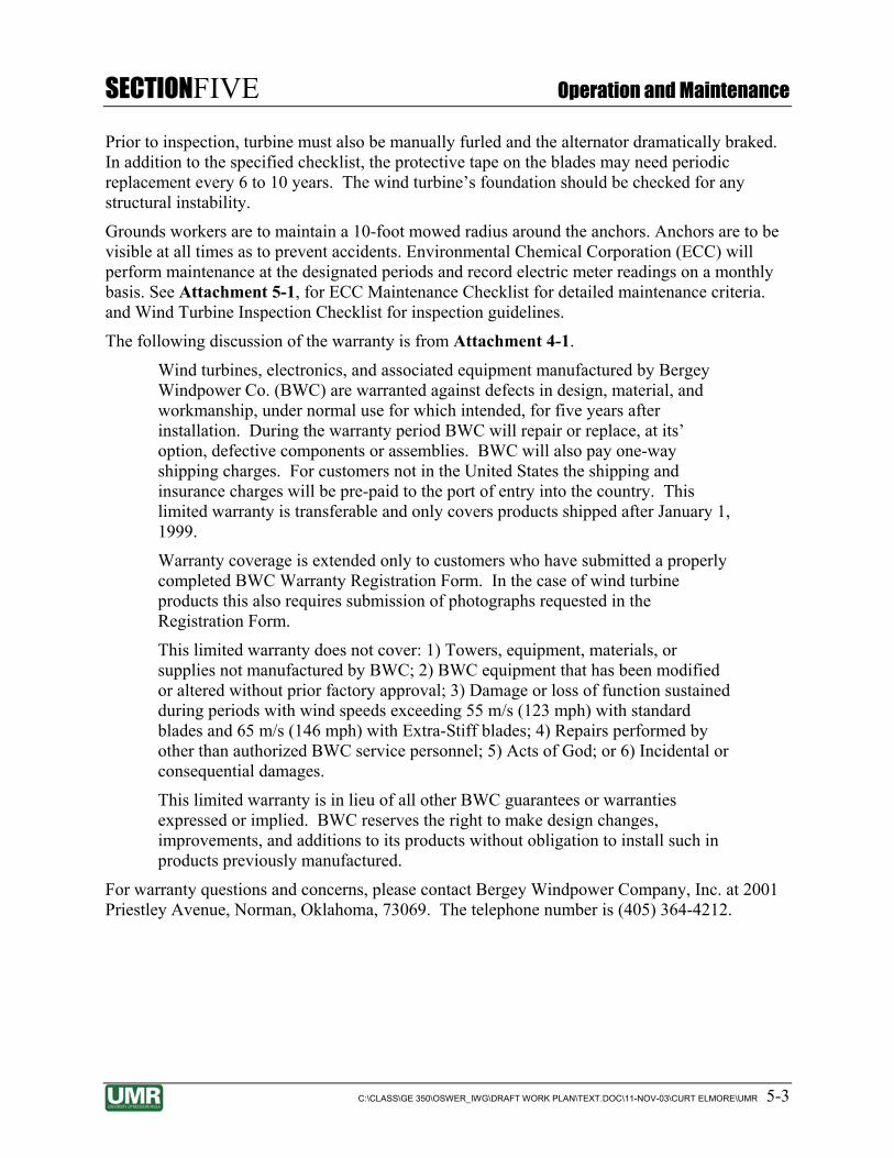
According to a geotechnical investigation at the nearby main treatment plant, the former NOP site contains a loess material, which will determine the soil properties used (Woodward-Clyde, 1999). Woodward-Clyde (1999) geotechnical investigation report stated that the floor slabs and foundations should be designed for a maximum soil bearing capacity of 2,500 psf. The Bergey Installation Manual requires that the tower base pad, with the specified dimensions of 2.5 square feet (sq ft), be placed on soil with a minimum bearing capacity of 4,000 psf. In order for the tower base pad to accommodate the 2,500 psf bearing stress, the size will have to be increased beyond what is specified in the manual. A foundation 48 in. in diameter will adequately distribute the stress of the tower without exceeding the recommended 2,500 psf bearing stress. Figure 4-5 shows four vertical reinforcing bars will be centered in the foundation form on a 28 in square which will maintain a 4 in concrete clearance. The length of the reinforcing bars will be 44 in which will provide a 2 in concrete clearance at each end of the foundation. A pier pin shown in Figure 4-6 provided by the tower manufacturer will be cast into the top of the foundation. The depth of the foundation needs to exceed the estimated frost depth which is given as 3.5 ft by Woodward-Clyde (1999). Therefore, the foundation will be 4 ft deep. Attachment 4-2 shows the calculations used for this foundation design.
The foundation preparation will include obtaining underground utility clearance, and excavation of all topsoil at the tower foundation location and the three anchor locations. The topsoil may be used for landscape material at other locations. Precautions shall be taken to minimize the disturbance of soils surrounding the foundation excavation.
The loess soil is reported to be susceptible to frost heave. Precautions need to be taken to prevent differential settlement of the tower pad. As recommended in the Woodward-Clyde (1999) geotechnical investigation for the site, the consolidation of the slab embedment extends 3.5 ft below finish grade. The finished earth grade will be graded to direct surface water away from the foundation slab. Bare soil will be covered with excavated topsoil and will be seeded with grasses to prevent erosion. The guy wire anchors and the tower slab sub-grade will be backfilled with 6 in loose lifts of well-graded soil not consisting of any construction debris, organic material, or aggregate having a diameter greater than 4 in. If granular material is encountered in the on site excavation, then it shall be mixed with the loess soil to obtain a well-graded consistency. The compaction requirement of 4,000 psf bearing capacity will be assumed achievable with proper construction methods. These methods will consist of using a hand-operated vibratory compactor on each 6 in backfilled lift. Water shall be added to the backfill if the soil is in a dry, dusty state.
4.1.4 Potential Future Modifications to Wind System One of the reasons that wind power is so advantageous over conventional electricity is the fact that not only is wind free, non-polluting, and renewable, but wind power can be generated in areas where running an electric grid can be extremely costly. One potential future modification that can be implemented to the wind turbine system design is a conversion of the Grid Inter-tie System to an off grid system. This conversion would allow the GCW’s to be completely self-sufficient and they could be installed and operated at remote locations where grid electricity does not already exist. The cost of converting a Grid Inter-tie system to an off grid system is on the order of $10,000 as per the teleconference record presented in Attachment 4-3. Please note that the conversations documented in the teleconference records were conducted prior to the

SECTIONFOUR Installation of Wind Turbine System
C:\CLASS\GE 350\OSWER_IWG\DRAFT WORK PLAN\TEXT.DOC\11-NOV-03\CURT ELMORE\UMR 4-5
completion of the design. Some of the selected system elements may be significantly different from those initial conversations. For example, a 120 ft tower was discussed, but a 100 ft tower was selected.
In order to ensure that a constant supply of power can be maintained the off grid system requires that batteries be added to the wind turbine system to store excess power. This power will then be converted from direct current (DC) to AC via an inverter and will be used when there is not enough wind to power the system.
The Texas Electronics Series WSC-5 Wind Speed Activated Control system is designed for switching on and/or off, various types of equipment (such as deodorizers, air samplers, alarms, beacons, and wind turbines) when wind speed exceeds or falls below a certain selectable control value. This system could also be used to activate a drainage system for off-grid situations where sufficient power is no longer being supplied by the wind turbine (Texas Electronics, 2003). Thus preventing freeze problems.
4.2 MODIFICATIONS TO EXISTING GCW
4.2.1 Freeze Protection During normal operation, it is not expected that the water flowing through the GCW system would freeze during very cold weather. However, if the water flow ceases due to an electricity outage, regardless of the power source, the system could experience severe damage due to freezing water.
Existing freeze protection in the GCW pilot system consists of a small electric space heater placed within the vault. The space heater draws a significant amount of current and the temperature produced is not consistent. It is also dependent upon constant electrical power thus making it non-functional during a long power outage. Though this freeze protection is functional, there are other possible and more efficient methods of keeping the pipes and pump operational. Future GCW systems will be constructed with freeze protection built-in. This includes dump valves on the systems to release the water in cases of power outages.
A Nebraska winter will record temperatures well below freezing causing the recharge and pipelines with static water to freeze. The expansion of the freezing water will likely cause the pumps and pipes to break. One option to prevent this includes inexpensive housing insulation, such as R18, rated for the Nebraska area or a similar product could be wrapped around the pump and pipes and secured by duct tape to keep the GCW from freezing. This approach uses the concept that the groundwater is significantly warmer than the ambient air temperature during the winter, and a possibility is that the heat difference could be maintained to prevent freezing. This method may prove to not be as effective during the cold months. In addition, reflective insulating tape can be used on piping.
Dump valves can be installed on the pumps and pipes. The air stripper tank should be fine in freezing temperatures, since the only water that stands in it when not running sits in the bottom tank. The air stripper tank’s cap does not expand from freezing water. All of this freeze protection is not necessary if the system continues to run continuously. The rationale for preparing the system for freezing temperatures is that future modifications, include the possibility of an off grid system. This would mean the GCW system would be powered from the

SECTIONFOUR Installation of Wind Turbine System
C:\CLASS\GE 350\OSWER_IWG\DRAFT WORK PLAN\TEXT.DOC\11-NOV-03\CURT ELMORE\UMR 4-6
wind turbine only. Insufficient wind would cause the system to shut down. The water would stop moving allowing for freezing to occur. Additional methods for keeping the GCW winterized and to cut down on power consumption is to add insulation to the building where the treatment system is located and to add heating tape to the exposed pipe carrying water. The freeze protection modifications are outside the scope of this project. However, the discussion has been included in the event that others elect to use freeze protection methods other than space heaters.
4.2.2 Potential Future Modifications to GCW Initiating the startup of the GCW system requires a high amount of power from the wind turbine system. This surge in power consumption is not a problem while the wind turbine is connected to the Grid Inter-tie System, but if the wind turbine were off grid, the power consumption might be too great to power the GCW system simultaneously. If the wind turbine is to be converted into an off grid system, a future modification may have to be applied that reduces the power consumption at start-up. One way to offset such a high power consumption need is to add a relay to the system so that all of the GCW components are not starting at the same time. This offset in start-up should give the wind turbine enough time to produce adequate power to keep the system running smoothly.
Another potential future modification for the GCW is to add a switch to the system that only allows water treatment to occur when there is sufficient wind to power the wind turbine. The system would only let the Grid Inter-tie power function when the wind turbine is working. This type of system has never been implemented before so it will be a pilot program to see if there is more contaminant mass removed by running the GCW system constantly or if more contaminant mass is removed by treating the groundwater intermittently. Since there are already monitoring systems in place at the GCW, additional monitoring should not be required.
4.3 SYSTEM INSTRUMENTATION
Overview Modifications will be made to the system in order to:
1. Measure the electrical output (kWh) of the wind turbine
2. Measure the electrical consumption (kWh) of a raw water process device such as the water well pump.
The development of the power metering is discussed in Section 6.
Data Collection Platform The heart of this study’s instrumentation is a device that will record the data outputs from the various sensors. A commonly used device is a datalogger which collects electronic output from the various sensors. The output is then recorded on a time basis, which is downloaded onto a laptop computer. The datalogger for this study will be a Campbell Scientific Instruments (CSI) 21X. This device is ready for use since was previously purchased by R. Gallagher for another study. By reuse of the existing 21X this study will not have to purchase another one costing $2,500.

SECTIONFOUR Installation of Wind Turbine System
C:\CLASS\GE 350\OSWER_IWG\DRAFT WORK PLAN\TEXT.DOC\11-NOV-03\CURT ELMORE\UMR 4-7
Wind Turbine Instrumentation Standard with the BWC EXCEL-S Power Processing Center is a real time display of operating status, turbine rotor speed, and output power. Consultation with BWC’s application engineer reveals that it is not possible to tap the datalogger into the Processing Center. Since a continuous recording of the power output is needed for further analysis a watt transducer is needed to send a 0 to 10 volt analog signal to the electronic data recorder. The watt transducer recommended for use by the Ohio Semitronics application engineer “Rich” is a PC5-113 (for 240 VAC, 3 phase). This replaces the previously specified watt/watt-hour transducer W-059AT. This substitution is to reduce the cost of instrumentation since the W-059AT will cost $505 whereas the PC5-113 cost is $400. To duplicate the results of the watt/watt-hour transducer we will need to calculate the watt hours via the time intervals provided by the datalogger. This cost savings will greatly enhance the needed purchase of another watt transducer to measure power consumption of the water well pump.
Currently, a requested has been submitted to OPPD for a watt-hour meter to install between the wind system inverter and the 60 amp breaker that is used to send power to the GCW system.
WATER WELL PUMP INSTRUMENTATION Power consumption by the water well pump will be measured indirectly by using a CSI 10-L current sensor. Using these readings and historical electrical grid charges the estimated number of kWh of power consumed by the raw water process equipment will be established.
AIR STRIPPER INSTRUMENTATION Ideally, another watt transducer is needed at this device the measure the power consumption. Because of budget constraints, it will be necessary to calculate the power consumption values using the measured current readings from the water well pump.
WIND INSTRUMENTATION Wind speed and direction values will be gathered from a near-by weather stations operated by the High Plains Regional Climate Center.
DATALOGGER SOFTWARE The existing software will be used to program and download data from the logger.
SURGE PROTECTION Electrical surge protection will be provided by the Campbell surge protector (CSI SVP 48) and associated terminal block (CSI 8206). Essential to success is the establishment of a electrical ground. It is believed that two grounding rods will provide the needed ground. They will be tested using a “Meggar” meter.

SECTIONFOUR
C:\CLASS\GE 350\OSWER_IWG\DRAFT WORK PLAN\TEXT.DOC\11-NOV-03\CURT ELMORE\UMR 4-8
4.4 PERMITTING Several investigations resulted in the listing of the former NOP site on the National Priorities List under Section 105 of the CERCLA on August 30, 1990. In September, the U.S. Army Corps of Engineers, the US EPA, and the Nebraska Department of Environmental Quality entered into an Interagency Agreement under Section 129 of CERCLA to investigate and control contamination at the former NOP site.
CERCLA Section 121(d) requires that activities performed at the site comply with all federal, state, and local applicable or relevant and appropriate requirements (ARARs).
Permitting is a form of ARARs. The substantive requirements of all permits must be met, but actual permits are not required. The wind power demonstration project will be conducted on site, and thus all activities will be conducted under the existing CERCLA project. Therefore, the substantive requirements of any potentially applicable permits must be met, but actual permits are not required. In some residential communities, concern regarding noise levels created by the wind turbine may be factors in issuing construction permits, but the project site is located on federal property which is used for U.S. Army Reserve training. Therefore, noise levels are not a concern for this project.
To the best of the designers’ knowledge, formal permitting is not required for the installation and operation of a wind turbine system.
The current wind power demonstration project is scheduled for a total project duration of one year. In the event that the demonstration project time period is significantly extended or a permanent wind power project is undertaken at the project site, the project owners are advised to consider establishing a binding wind easement according to Chapter 66 of the Revised Nebraska Statutes.
Informal coordination with the utility company, OPPD, was initiated on September 26, 2003 via teleconference. A record of that teleconference is included in Attachment 4-3. It is expected that a standard interconnection contract will be executed with OPPD.
An additional permitting concern is regulation of tall structures by the Federal Aviation Agency (FAA) with regards to potential aircraft hazard. The memorandum included in Attachment 4-3 documents that the wind turbine is not required to include warning lights because the site is beyond applicable threshold distances from the nearest airstrip. However, negotiations are on-going with the Nebraska National Guard to appropriately illuminate the site as a warning to military aircraft which may perform training over the site.

SECTIONFIVE Operation and Maintenance
C:\CLASS\GE 350\OSWER_IWG\DRAFT WORK PLAN\TEXT.DOC\11-NOV-03\CURT ELMORE\UMR 5-1
5. Section 5 FIVE Operation and Maintenance
5.1 WIND TURBINE OPERATION The BWC EXCEL-S Wind Turbine system is automated and self-sufficient. Operation will begin immediately upon installation. Various electrical components are used to facilitate automated operation. Wind energy is used to run a turbine with an electromagnet that produces a charge in the rotor head. This charge is stored and converted in the mastermind inverter. The turbine produces power in the form of 240 VDC, single-phase electricity. The GridTek 10 power processor converts the charge into useable 220 VAC at 92 percent efficiency and then distributes throughout the GCW system by the 60 amp dual pole circuit box (BWC, 1999). The turbine will be operated from December 4, 2003, until September 30, 2004. Potential future modifications that will possibly change the operating procedures are discussed in section four. An addendum to this document will be proposed after the end of the pilot study.
The wind turbine system is designed to become inoperable during abnormal environmental conditions. During periods of severe winds, the system will automatically furl; that is, turn so that the turbine is not facing directly into the wind, thereby slowing the turbine’s rotational velocity. If the system experiences excessive vibration, heavy icing, severe weather, or makes unusual noises, manual furling can eliminate risk of harm to the system. Manual furling is also necessary, along with stopping the alternator during periodic system inspections. As a second precautionary measure, should the system experience a voltage fluctuation or other anomaly, the GridTek 10 disconnects the turbine from the power grid. The turbine will be allowed to spin, but will no longer provide energy to the system.
5.2 WIND TURBINE MAINTENANCE The BWC Excel-S installation should be inspected 30 days and 180 days after installation. Furthermore, the installation and system should be inspected every two years and after any particularly severe weather. Scheduled inspections should take place only when the wind is below 16 mph. Maintenance and inspection checklists are presented in Attachment 5-1. The initial inspection on the day of erection should follow this checklist as well. Troubleshooting and repair guides are provided starting on page 44 of the Bergey Installation Manual (Attachment 4-1).
Checklist for Inspections
1. Inspect each anchor point. Ensure hardware is secure and guy wires are tensioned properly. Check Big-Grips to ensure no strands are broken.
2. Furl the wind turbine and check that the damper restricts the tail’s unfurling to a period of at least three seconds when the winch cable is rapidly released.
3. Furl the turbine and short the alternator using the procedure given in the following inspection procedures. Climb the tower. Always use proper safety belts and lanyards.
4. Inspect blades for: i. Cracks around the hub or just past the long stiffener pad.
ii. Condition of the leading edge protection tape, particularly outboard of the pitch weight.
iii. Erosion of the lead weight on the pitch wedge. iv. Tip damage.

SECTIONFIVE Operation and Maintenance
C:\CLASS\GE 350\OSWER_IWG\DRAFT WORK PLAN\TEXT.DOC\11-NOV-03\CURT ELMORE\UMR 5-2
5. Remove the spinner and hang it from the machine. Check the torque on the blade nuts; the recommended value is 150 ft-lbs. Check the front bearing seal integrity and grease loss. Reattach the spinner and check that it is secure.
6. Open the nacelle; use a small rope to lash the hatch open. 7. Inspect the flanged connection between mainframe and alternator. Check torque on
each bolt; the recommended value is 80 ft-lbs. 8. Check the rear alternator bearing for seal integrity and grease loss. 9. Inspect mainframe for cracks. 10. Remove the slip-ring cover plate. Inspect for:
i. Check brushes for ease of movement in the brush holder. ii. Check slip rings for signs of arcing damage.
iii. Check that no grease from the yaw bearings has leaked on the slip-rings. 11. Inspect damper. Some leakage around the front seal is okay. 12. Inspect the furling cable (particularly at the ball end/fork attachment to the tail boom)
and furling cable conduit. 13. Check for cracks or loose hardware on the tail boom and fin. 14. Check the tail pivot and particularly its snap ring fasteners. 15. Close the nacelle and check that all of its fasteners are secure. 16. while descending the tower, inspect the following:
i. Check that the tower wiring is properly secure. ii. Check all fasteners
iii. Look for any cracks in the tower structure. iv. Check the condition of the guy wire attachment. v. Check the furling cable.
17. Check the furling winch and make sure that the furling cable is not twisted up. If the cable is twisted, check the swivel.
18. Check the connection on all ground rods and hardware. 19. Use a volt-ohm meter (VOM) to check the surge arrestors. 20. Remove the alternator shorting connection. Check the disconnect switch. 21. Switch the disconnect switch to “OFF” and unfurl the wind turbine. Listen to the
sound of the machine as it speeds up. No mechanical sounds, such as a “clunking” or “banging”, should be heard. Also watch for any new or significant vibrations. The turbine operation should be very smooth.
22. Inspect the wire run, particularly all electrical connections. 23. Use a Meggar to check the three-phase wiring from the turbine to the controller (the
procedure is the same as used for commissioning). 24. Use a VOM to check that the three legs of the AC output of the wind turbine are
balanced. 25. Inspect the aluminum extrusion heatsink on the BWT-10240 inverter to assure that air
flow is not blocked. Further instruction for inverter maintenance is found on page 6-1 of the Owners Manual.
26. Check the controller per the instructions provided in the Owner’s Manual. NOTE: A service inspection checklist can be found in the Appendix of the Owner’s Manual.
SECTIONFIVE Operation and Maintenance
C:\CLASS\GE 350\OSWER_IWG\DRAFT WORK PLAN\TEXT.DOC\11-NOV-03\CURT ELMORE\UMR 5-3
Prior to inspection, turbine must also be manually furled and the alternator dramatically braked. In addition to the specified checklist, the protective tape on the blades may need periodic replacement every 6 to 10 years. The wind turbine’s foundation should be checked for any structural instability.
Grounds workers are to maintain a 10-foot mowed radius around the anchors. Anchors are to be visible at all times as to prevent accidents. Environmental Chemical Corporation (ECC) will perform maintenance at the designated periods and record electric meter readings on a monthly basis. See Attachment 5-1, for ECC Maintenance Checklist for detailed maintenance criteria. and Wind Turbine Inspection Checklist for inspection guidelines.
The following discussion of the warranty is from Attachment 4-1.
Wind turbines, electronics, and associated equipment manufactured by Bergey Windpower Co. (BWC) are warranted against defects in design, material, and workmanship, under normal use for which intended, for five years after installation. During the warranty period BWC will repair or replace, at its’ option, defective components or assemblies. BWC will also pay one-way shipping charges. For customers not in the United States the shipping and insurance charges will be pre-paid to the port of entry into the country. This limited warranty is transferable and only covers products shipped after January 1, 1999.
Warranty coverage is extended only to customers who have submitted a properly completed BWC Warranty Registration Form. In the case of wind turbine products this also requires submission of photographs requested in the Registration Form.
This limited warranty does not cover: 1) Towers, equipment, materials, or supplies not manufactured by BWC; 2) BWC equipment that has been modified or altered without prior factory approval; 3) Damage or loss of function sustained during periods with wind speeds exceeding 55 m/s (123 mph) with standard blades and 65 m/s (146 mph) with Extra-Stiff blades; 4) Repairs performed by other than authorized BWC service personnel; 5) Acts of God; or 6) Incidental or consequential damages.
This limited warranty is in lieu of all other BWC guarantees or warranties expressed or implied. BWC reserves the right to make design changes, improvements, and additions to its products without obligation to install such in products previously manufactured.
For warranty questions and concerns, please contact Bergey Windpower Company, Inc. at 2001 Priestley Avenue, Norman, Oklahoma, 73069. The telephone number is (405) 364-4212.

SECTIONSIX System Monitoring
C:\CLASS\GE 350\OSWER_IWG\DRAFT WORK PLAN\TEXT.DOC\11-NOV-03\CURT ELMORE\UMR 6-1
6. Section 6 SIX System Monitoring
6.1 POWER CONSUMPTION
6.1.1 Historical Power Consumption at GCW-1 The historical power consumption records for the GCW-1 site for the periods of June 2000 through December 2000 and January 2003 to August 2003 is outlined in Attachment 6-1.
Data collected from the initial 216 days of operation in 2000 indicates a total power usage of 19,032 kWh. During this time span, an estimated 12,247,000 gallons of water, measured by a flow meter, was treated. The system averaged 1.57 kWh was purchased per 1,000 gallons of water treated (URS, 2001).
Data collected in 2003 indicates that in 243 days, power consumption totaled 14,664 kWh. The total volume of water treated in 2003 is estimated using the number of operational days and a pumping rate of 50 gpm. During its 243 days of operation, GCW-1 is estimated to have treated 13,778,000 gallons of water. During this time, the system is estimate to have averaged 1.07 kWh purchased per 1,000 gallons of water treated (ECC, 2003).
The disparity between the average power consumption can be traced to a number of factors including the lack of treated water quantity data. In 2000, heater units were installed and run continuously during sub-freezing weather. In 2003, these same units were in place but had been supplemented with building insulation, thus increasing the heating efficiency. Comparing 2003 power consumption with 2000, the assumption is made that GCW-1 was not operated constantly from May to July. These factors explain the fluctuating system operation between 2000 and 2003 system.
6.1.2 Plan for Measuring Electric Consumption The current system is set up to measure grid power consumption with an OPPD kWh meter on the incoming power supply. The Operation and Maintenance (O & M) provider, ECC, will monitor the system and will record the power meter readings on a monthly basis. Line diagrams for the existing and proposed electrical systems follow as Attachment 6-2 and are discussed with more detail in Section 6.2.2.
6.2 POWER GENERATION
6.2.1 Anticipated Power Generation Accurate wind speed is crucial to the prediction of wind power generation. Wind energy is proportional to the wind v3. For example if the wind velocity were doubled then the power produced would be eight times as great. In 1994, the Nebraska Power Association (NPA) and other renewable energy interests, including the Nebraska Energy Office, agreed to participate in a multi-year study of eight wind sites in the state for their wind energy producing potential (NPA, 1999). During the four years of the study, average annual wind speeds ranged from 13.9 to 16.8 mph with the highest speeds generally in the early afternoon. The average wind speed of

SECTIONSIX System Monitoring
C:\CLASS\GE 350\OSWER_IWG\DRAFT WORK PLAN\TEXT.DOC\11-NOV-03\CURT ELMORE\UMR 6-2
14.4 miles per hour was recorded at Wahoo, Nebraska, approximately 15 miles from GCW-1 (OPPD, 1999). Both wind speeds correspond to the wind maps provided as Figures 3-4 and 3-5.
The Bergey WindCad Performance Model (BWC, 1997) is a model which takes wind probability into consideration when calculating total annual energy output. Since wind speed fluctuates, it is incorrect to use a simple average wind speed to calculate total energy production. Instead, wind speed probability is used to compensate for the variation of wind speeds over time. Wind speed probability is calculated using a Weibull probability distribution. A Weibull curve is a wind speed frequency diagram that illustrates how often the wind blows at a various speeds. The shape of this frequency diagram is a large determinant in the annual power output of a wind turbine. Using a general Weibull curve, WindCad is used to predict power production for the Excel 10 kW wind turbine under various wind loads. Using the NPA data with the WindCad Turbine Performance Model annual energy output was found to be approximately 16,617 kWh (Figure 6-1).
6.2.2 Plan for Measuring Electric Consumption The electrical layout uses two kWh meters placed side by side and turn opposite of each other; see Attachment 6-2. The first kWh meter (M1) will record imported power to the system and the second (M2) will meter exported power. The second meter will register all power created in excess of system demands. A third meter (M3) is needed to better understand the fluctuating nature of wind power. This third meter will be installed, between the new wind turbine disconnect switch and the pump building panel, to meter total power generated by the wind turbine. With simple calculations it would then be possible to quantify the GCW’s power consumption. These calculations are as follows:
321 MMMDemandTotalPower +−=
Where:
M1 = Import Meter, kWh/month
M2 = Export Meter, kWh/month
M3 = Generation Meter, kWh/month
The resulting total power demand is the actual amount of power used by the GCW during a given month. The total power demand is necessary for calculating the remediation efficiency of the system. It is also essential in evaluating the fiscal efficiency of the wind turbine system. Though the system is attached to a data logger, monthly monitoring of the power meters is still required. This monitoring and manual logging will be the responsibility of the O&M provider.

SECTIONSIX System Monitoring
C:\CLASS\GE 350\OSWER_IWG\DRAFT WORK PLAN\TEXT.DOC\11-NOV-03\CURT ELMORE\UMR 6-3
6.3 CONTAMINANT MASS REMOVAL By conducting water sample analysis from the influent and effluent streams for contaminant concentration levels, the contaminant mass removal can determined. GCW-1 is performing remediation of TCE contamination of the groundwater. The treatment system has a flow meter to measure the total gallons that have moved through the system. A correlation between power generation and consumption versus gallons of water treated and/or mass of TCE removed can be estimated. The Standard Operating Procedure (SOP) for groundwater analysis presented in Attachment 6-3 outlines the procedures for collecting and analyzing water samples. The Quick Test Water Analysis for Volatile Organic Halides (Quick Test) will be the field test kit for determining the TCE concentrations (Elmore, Travaglin, Triplett, 2002).

SECTIONSEVEN Economic Analysis
C:\CLASS\GE 350\OSWER_IWG\DRAFT WORK PLAN\TEXT.DOC\11-NOV-03\CURT ELMORE\UMR 7-1
7. Section 7 SEVEN Economic Analysis
7.1 HISTORICAL GCW OPERATION COSTS GCW-1 went into operation at the beginning of June 2000, and it is assumed GCW-1 was operated constantly. It is also assumed that the submersible pump, centrifugal pump, and centrifugal blower were the reasons for power consumption. A heater was installed at the GCW-1, but specific electrical consumption of the heater is unknown. The historic operation cost records for the GCW-1 site for the periods of June 2000 through December 2000 and January 2003 to August 2003 are outlined in Figure 7-1. The historic annual chemical feed cost was $700 (Elmore & Graff, 2002).
Data collected from the initial 182 days of operation indicate a total operational cost of $1,143. The total cost includes basic service, kWh usage, and sales tax. The average total operation cost per month during this time was $191. The average total cost per kWh over the six-month span was approximately $0.08. For every 1,000 gallons of water treated, the average energy cost was $0.10. The estimated total annual cost for 2000 was $2,987.
Data collected in 2003 indicates a total power consumption of 14,664 kWh in 243 days, resulting in a total cost of $1,017. The average total operation cost per month during this time was $127. The average total cost per kWh over the eight month span was approximately $0.08. The estimated total annual cost for 2003 was $2,225.
7.2 CAPITAL COSTS The capital cost for installation of the Bergey wind turbine has been divided into separate component categories to demonstrate individual costs. A summary of the capital costs is located in Figure 7-2. The separate cost components include electrical components, construction supplies, rental equipment, and labor. Included under each component is a percentage markup to cover miscellaneous expenditures. The miscellaneous category of the electrical subunit was calculated using twenty percent of the total material costs. The miscellaneous category of the supplies subunit was calculated using ten percent of the total material cost. The labor includes a ten percent markup to compensate for overhead and profit margins.
Electrical component subtotal is $245. The construction supplies subtotal is $881.
The rental equipment subtotal is approximately $2,225. The labor subtotal is $2,464. Two additional laborers were included for tower assembly as a precaution against underestimating the total. The estimated total capital cost for the project is $5,815.
7.3 ANNUAL COSTS The following annual cost estimations are based on data found in Figure 7-3, assuming that GCW-1 will run continuously 24 hours a day, 365 days a year. In estimating an annual cost with limited and uncertain data, the assumption is made that no one month could be considered absolutely correct, so kWh used, cost of electricity, and total cost were all individually added up and then divided by the number of months with data available. In 2003, the system used 1,833 kWh a month with a kWh cost of $127. The electricity purchased averaged out to a cost of $0.08 per kWh, based on an average historic utility rate ranging from $0.07 to $0.11 per kWh. Annual kWh usage was calculated using the 2003 data. The 2003 annual energy consumption of GCW-1

SECTIONSEVEN Economic Analysis
C:\CLASS\GE 350\OSWER_IWG\DRAFT WORK PLAN\TEXT.DOC\11-NOV-03\CURT ELMORE\UMR 7-2
was 21,996 kWhs, at a cost of $1,525. The estimated average daily electricity consumption of the system was 60.3 kWhs. The projected annual energy output of the wind turbine is estimated to be 16,617 kWhs (see Figure 6-2). After accounting for the annual energy output of the wind turbine, the total annual kWh usage from the utility grid is approximately 5,379 kWh. Using $0.08/kWh, the estimated yearly cost of utility grid power is $430.
The 2003 data is used because of improvements to the system which decreased power consumption, and it is more representative of the current GCW system. In 2000, heater units were installed and ran continuously during sub-freezing weather. In 2003, these same units were in place, but had been supplemented with building insulation, increasing the heating efficiency. Comparing 2003 power consumption with 2000, the assumption is made that GCW-1 was not operated constantly from May to July of 2000. These factors explain the fluctuating system operation between 2000 and 2003 system.
The ECC must inspect the wind turbine system 30 and 180 days after installation. Using the General Labor Rate (see Figure 7-2), and an eight-hour day for each inspection, the cost of inspection is $320. Inspection of the wind turbine system must also occur after severe storms, so this cost will vary annually. The grass mowing around the guy anchors will also vary annually. Additional funds will have to be allocated to cover these contingencies as necessary.
7.4 TCE MASS REMOVED PER KWH Approximately 24 gallons of TCE was removed from 13 million gallons of water circulated through the system, with zero net water loss (Elmore& Graff, 2002). This value allows a ratio to be determined between the TCE and water removed from the ground. The ratio can then be used to determine the gallons of TCE removed in the remediation process.
Data collected in 2000, indicates approximately 12,247,000 gallons of water was treated. The amount of TCE removed was close to 22.6 gallons. Each kWh consumed removed approximately 6.5 grams of TCE.
Data collected in 2003, indicates approximately 13,778,000 gallons of water was treated. The amount of TCE removed was close to 25.43 gallons. Each kWh consumed removed approximately 9.53 grams of TCE. Attachment 7-1 shows calculations of the removed quantities.
7.5 WIND TURBINE COST ESTIMATE The BWC Excel-S wind turbine system estimate is included as Figure 7-3. The wind turbine total cost estimate of $30,730 includes shipping and handling, the 10kW BWC Excel-S, Grid-Tek 10 inverter, 100 foot guyed lattice tower kit (XLG30), tower wiring kit (XTWK30), and the standard five year warranty (BWC, 2003). Please note that delivery costs have not been included in the estimate.
7.6 PROJECTED GCW OPERATION COSTS WITH WIND TURBINE System operation costs for 2003 are estimated as $2,225 (see Figure 7-1). Supplemental wind energy will decrease operation cost. The WindCad Turbine Performance Model estimated the annual energy output for the 10-kW system to be approximately 16,617 kWh (Figure 6-2).

SECTIONSEVEN Economic Analysis
C:\CLASS\GE 350\OSWER_IWG\DRAFT WORK PLAN\TEXT.DOC\11-NOV-03\CURT ELMORE\UMR 7-3
Based on a cost of $0.08 per kWh, the wind turbine system should save $1,329 annually. The wind turbine system must be inspected by the ECC 30 days and 180 days after initial start up. These inspections should take 8 hours each. Based on the general labor rate used in Figure 7-2, these inspections will cost approximately $320. Combining savings with expenses, GCW-1 annual operation costs are projected at $1,216.
A present worth analysis was done using annual operation and maintenance costs. 2003 cost data is more representative of the GCW-1 system. A conservative annual cost of $1,250 was used with a 5% interest rate and 30 year system life. This calculation yielded a present worth value of $19,216. See present worth calculations in Attachment 7-1.
If electrical efficiency is improved by 20%, annual operation cost will total $911. This annual cost yields a present worth value of $14,004.

SECTIONEIGHT Project Schedule
C:\CLASS\GE 350\OSWER_IWG\DRAFT WORK PLAN\TEXT.DOC\11-NOV-03\CURT ELMORE\UMR 8-1
8. Section 8 EIGHT Project Schedule
The outlined schedule is based on the goal of having a renewable energy source powering the groundwater remediation system on or before the week prior to UMR graduation – December 20, 2003. It is assumed that turbine system delivery may require five weeks. Therefore, the anchors and bolts for the foundation must be delivered prior to tower and turbine delivery so that the foundations may be constructed and given adequate time to cure. Other schedule rationale includes contract procurement, tower installation, and system startup.
• Contract Procurement-UMR
• Location Staking-UMR
• Anchor Delivery-Bergey Windpower Company, Inc.
• Foundation Cure Time – 14 days
• Tower and Turbine Delivery- Bergey Windpower Company, Inc.
• System Installation and Startup- Construction contractor.
Figure 8-1 details the project schedule.

SECTIONNINE Construction Plan
C:\CLASS\GE 350\OSWER_IWG\DRAFT WORK PLAN\TEXT.DOC\11-NOV-03\CURT ELMORE\UMR 9-1
9. Section 9 NINE Construction Plan
9.1 SUBCONTRACTING PLAN The overall objective of this project is the demonstration of the use of a renewable energy source, specifically wind power, to power a groundwater remediation system. The demonstration requires the procurement of a commercial wind turbine and the installation of this turbine. Completion of this project requires the awarding of two contracts. As previously stipulated, the wind turbine system is being provided by Bergey Windpower Company, Inc. The construction of the tower is divided into three phases of work, including (1) foundation and anchor construction, (2) tower construction, and (3) installation of electrical components. All three phases of tower construction will be awarded to a local construction company. Procurement and Scope of Work outlines follow as Attachments 9-1 and 9-2.
• Attachment 9-1: Wind Turbine System Procurement, Bergey Windpower Company, Inc.
• Attachment 9-2: System Construction and Installation, Contractor to be determined.

SECTIONTEN References
C:\CLASS\GE 350\OSWER_IWG\DRAFT WORK PLAN\TEXT.DOC\11-NOV-03\CURT ELMORE\UMR 10-1
10. Section 10 TEN References
Bergey Windpower Company (BWC), 1997. 10kW EXCEL-S Windcad Performance Model [online]. www.bergey.com [Acessed October 2003].
Bergey Windpower Company (BWC), 1999. BWC Excel-S Windpower Generator Owner’s Manual and Parts List.
Bergey Windpower Company (BWC), 2002. Helping The Environment [online]. Available from: http://www.bergey.com [Accessed 15 September 2003].
Elmore, A. C., Travaglin, L. A., Triplett J. L., 2002. Field Analyses of RDX and TCE in Groundwater during a GCW Pilot Study. REMEDIATION. Winter.
Elmore, A.C. & Graff, T. 2001. A Case Study of the Beneficial Reuse of Treated Groundwater. REMEDIATION. Summer.
Elmore, A.C. & T. Graff. 2002. Best available treatment technologies applied to groundwater circulation wells. REMEDIATION. Summer.
Elliot, et. al. 1986. Wind Energy Atlas of the United States. Department of Energy Wind Energy Atlas of the United States [online]. Available from: http://rredc.nrel.gov/wind/pubs/atlas/ [Accessed 18 September 2003]
Environmental Chemical Corporation (ECC), 2003. GCW-1 2003 Electrical Consumption Summary. Transmitted September, 2003.
Omaha Public Power District (OPPD). 2003. One-line diagram of electrical components. Communication from Casey Malskeit. October.
Omaha Public Power District (OPPD) and Nebraska Power Association, prepared by Global Energy Concepts. 1999. Nebraska Wind Energy Site Data Study Final Report. May. [online] Available from: http://www.nol.org/home/NEO/reports/ne_wind_energy_site_data_study_1999.pdf [Accessed 20 October 2003].
Texas Electronics, 2003. [online] Available from: http://www.texaselectronics.com [Accessed 1 October 2003]
Woodward-Clyde, 1997. Final Record of Decision, Operable Unit 2, Former Nebraska Ordnance Plant, Mead, Nebraska. Prepared for U.S. Army Engineer District, Kansas City. Signed April 7, 1997.
URS Group, Inc. (URS). 2001. Draft Final Groundwater Circulation Well Pilot Study Technical Memorandum. Operable Unit No. 2 (Groundwater) Former Nebraska Ordnance Plant Mead, Nebraska prepared for U.S. Army Engineer District, Kansas City under Contract No. DACW41-96-D-8014 Task Order No. 0017. April.
U.S. Environmental Protection Agency (USEPA). (1990). NPL Site Narrative for Nebraska Ordnance Plant (Former) [online]. Available from: www.epa.gov/superfund/sites/npl/nar1262.htm [Accessed 9 September 2003].
Woodward – Clyde, 1999. Geotechnical Investigation Remedial Design Operable Unit No. 2 (Groundwater) Former Nebraska Ordnance Plant Mead, Nebraska, WCFS Project No. K96201.
Wind Turbine Industries Corporation (WTIC). (2003). Grid Intertie System. [online] Available from: http://www.windturbine.net [Accessed 1 October 2003].

Figures
C:\CLASS\GE 350\OSWER_IWG\DRAFT WORK PLAN\TEXT.DOC\11-NOV-03\CURT ELMORE\UMR

OSWER/IWGGroundwater Remediation Powered
by a Renewable Power Source
Draft Work Plan
University of Missouri-Rolla GE350 November 11, 2003
Figure 3-1 Site Location Map (Elmore & Graff, 2001)

OSWER/IWGGroundwater Remediation Powered
by a Renewable Power Source
Draft Work Plan
University of Missouri-Rolla GE350 November 11, 2003
Figure 3-2 Selected Remedy (Elmore & Graff, 2001)

OSWER/IWGGroundwater Remediation Powered
by a Renewable Power Source
Draft Work Plan
University of Missouri-Rolla GE350 November 11, 2003
Figure 3-3 GCW Elements (Elmore & Graff, 2002)

OSWER/IWGGroundwater Remediation Powered
by a Renewable Power Source
Draft Work Plan
University of Missouri-Rolla GE350 November 11, 2003
Figure 3-4 U.S. Annual Average Wind Power (Elliot et. Al., 1986)

OSWER/IWGGroundwater Remediation Powered
by a Renewable Power Source
Draft Work Plan
University of Missouri-Rolla GE350 November 11, 2003
Figure 3-5 Nebraska Wind Map (Elliot et. al., 1986)

OSWER/IWGGroundwater Remediation Powered
by a Renewable Power Source
Draft Work Plan
University of Missouri-Rolla GE350 November 11, 2003
Figure 4-1 System Configuration (WTIC, 2003)

OSWER/IWGGroundwater Remediation Powered
by a Renewable Power Source
Draft Work Plan
University of Missouri-Rolla GE350 November 11, 2003
Figure 4-2 Wind Turbine LocationBase map from (URS, 2001)

OSWER/IWGGroundwater Remediation Powered
by a Renewable Power Source
Draft Work Plan
University of Missouri-Rolla GE350 November 11, 2003
Figure 4-3 BWC Wire Size Recommendations (BWC, 1999)
Calculating Circular Mills (cm): Required (use for longer runs):
(K x | x L) / Vd = cm
Where Vd = 5.5 for Excel-S
Recommended Conduit Sizes: Includes #8 bond wire, assumes no more than two 90 degree bends in the conduit string.
Turbine ModelMaximum
3-phase AC Amps
Fuse Size,
Amps100-ft 200-ft 300-ft
Note: Listed wire sizes will provide no more than 10% loss at rated power.
Wire Run Length, Including Tower Height
34 35BWC EXCEL-S 240 VAC, 10 #6 AWG 13.3 mm2
Wiring PVC
Conduit Size3 x #6 1 1/2 inches 3 x #4 1 1/2 inches 3 x #2 1 1/2 inches
3 x 1/0 2 inches3 x 2/0 2 inches

OSWER/IWGGroundwater Remediation Powered
by a Renewable Power Source
Draft Work Plan
University of Missouri-Rolla GE350 November 11, 2003
Figure 4-4 Guy Wire Anchor Construction (BWC, 1999)
6 ft3 ft
1.5 ft
6 ft
Reinforcing bars across both faces with
maximum spacing of 1 ft
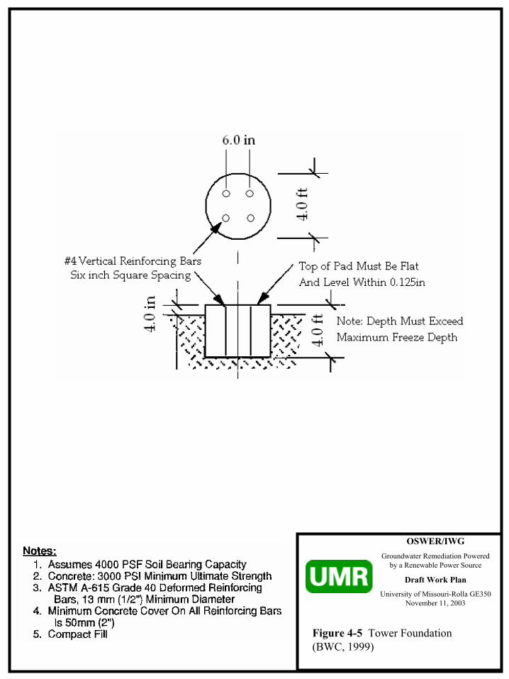
OSWER/IWGGroundwater Remediation Powered
by a Renewable Power Source
Draft Work Plan
University of Missouri-Rolla GE350 November 11, 2003
Figure 4-5 Tower Foundation (BWC, 1999)

OSWER/IWGGroundwater Remediation Powered
by a Renewable Power Source
Draft Work Plan
University of Missouri-Rolla GE350 November 11, 2003
Figure 4-6 Tower Connection Design Changes (BWC, 1999)

OSWER/IWGGroundwater Remediation Powered
by a Renewable Power Source
Draft Work Plan
University of Missouri-Rolla GE350 November 11, 2003
Figure 6-1 Historic Power Usage (URS, 2001 & ECC ,2003)
2000 Data
DatekW-hr month
Billing Days
kW-hr day
kW-hr Usage($)
Cost/ kW-hr ($)
Total Cost ($)
Total Cost/kW-
hr ($)
Est. Water
Treated (1000 gal)
kW-hr/1000
galJun-00 1200 33 36.3 92.86 0.08 105.76 0.09 1690.00 0.71Jul-00 1968 26 75.6 145.69 0.07 160.85 0.08 1060.00 1.86
Aug-00 3024 32 95 218.35 0.07 243.26 0.08 1830.00 1.65Sep-00 3288 31 106 211.62 0.06 230.08 0.07 1830.00 1.80Oct-00 2160 30 72 144.07 0.07 159.15 0.07 1760.00 1.23Nov-00 3624 30 121 225.06 0.06 244.19 0.07 2120.00 1.71Dec-00 3768 34 111 230.82 0.06 ? 1830.00 2.06
Totals 19032 216 1268.47 12120.00
1.57 Total 1000 gal/day 56.11
2003 Data
DatekW-hr month
Billing Days
kW-hr day
KW-hr Usage($)
Cost/ kW-hr ($)
Total Cost ($)
Total Cost/kW-
hr ($)Jan-03 1128 31 36.3871 75.24 0.07 82.74 0.07Feb-03 5160 28 184.2857 286.5 0.06 294 0.06Mar-03 3456 31 111.4839 230.51 0.07 245.26 0.07Apr-03 1440 30 48 96.05 0.07 103.55 0.07May-03 984 31 31.74194 69.32 0.07 76.82 0.08Jun-03 552 30 18.4 43.66 0.08 51.16 0.09Jul-03 408 31 13.16129 32.27 0.08 39.77 0.10
Aug-03 1536 31 49.54839 115.98 0.08 123.48 0.08
Totals 14664 243 949.53
13635 2003 Average kW-h per 100 1.075
* Assumed system operated 24/7*Assumed all electricity was consumed by pump** Estimated
Est.Total (1000 gal)
2000 Average kW-hr/1000 gal
OSWER/IWGGroundwater Remediation Powered
by a Renewable Power Source
Draft Work Plan
University of Missouri-Rolla GE350 November 11, 2003Limitations: This model uses a mathematical idealization of the wind
speed probability. The validity of this assumption is reduced as the time period under consideration (ie, the wind speed averaging period) is reduced. This model is best used with annual or monthly average wind speeds. Use of this model with daily or hourly average wind speed data is not recommended because the wind will not follow a Weibull distribution over short periods. Actual performance may vary.
Figure 6-2 WindCad Performance Model (BWC, 1997 & Global Energy Concepts, 1999)
WindCad Turbine Performance ModelBWC EXCEL-S, Grid - Intertie
Prepared For: UMR GE350Site Location: NOP Site Mead, NEData Source: Nebraska Power Association
Date: 10/27/2003
Inputs: Results:Ave. Wind (m/s) = 6.4 Hub Average Wind Speed (m/s) = 5.95
Weibull K = 2 Air Density Factor = 3%Site Altitude (m) = 360 Average Output Power (kW) = 1.90
Wind Shear Exp. = 0.270 Daily Energy Output (kWh) = 45.5Anem. Height (m) = 40 Annual Energy Output (kWh) = 16,617Tower Height (m) = 30.48 Monthly Energy Output = 1,385
Turbulence Factor = 17.0% Percent Operating Time = 76.1%
Weibull Performance CalculationsWind Speed Bin (m/s) Pow er (kW) Wind Probability (f) Net kW @ V
1 0.00 4.38% 0.0002 0.00 8.19% 0.0003 0.00 10.98% 0.0004 0.21 12.52% 0.0275 0.68 12.79% 0.0886 1.41 12.00% 0.1697 2.18 10.46% 0.2288 3.12 8.55% 0.2679 4.15 6.57% 0.27210 5.26 4.77% 0.25111 6.41 3.28% 0.21012 7.69 2.14% 0.16413 8.12 1.32% 0.10714 8.55 0.78% 0.06715 6.84 0.44% 0.03016 5.13 0.23% 0.01217 2.31 0.12% 0.00318 2.56 0.06% 0.00119 2.56 0.03% 0.00120 2.56 0.01% 0.000
1997, Bergey Windpow er Totals: 99.62% 1.897
10 kW

OSWER/IWGGroundwater Remediation Powered
by a Renewable Power Source
Draft Work Plan
University of Missouri-Rolla GE350 November 11, 2003
Figure 7-1 Historic GCW-1 Operation Costs (URS, 2001 & ECC, 2003)
2000 Data
DateKW-h Cost
($)
Total Cost/KW-
hr ($)
Chemical Feed Cost
($) Total Cost
($)Jun-00 105.76 0.09 58.33 164.09Jul-00 160.85 0.08 58.33 219.18
Aug-00 243.26 0.08 58.33 301.59Sep-00 230.08 0.07 58.33 288.41Oct-00 159.15 0.07 58.33 217.48Nov-00 244.19 0.07 58.33 302.52Dec-00 n/a n/a 58.33 n/aTotal 1143.29 n/a 408.31 1551.60
Average 190.55 0.08 58.33 248.88
2003 Data
DateKW-h Cost
($)
Total Cost/KW-
hr ($)
Chemical Feed Cost
($) Total Cost
($)Jan-03 82.74 0.07 58.33 141.07Feb-03 294.00 0.06 58.33 352.33Mar-03 245.26 0.07 58.33 303.59Apr-03 103.55 0.07 58.33 161.88May-03 76.82 0.08 58.33 135.15Jun-03 51.16 0.09 58.33 109.49Jul-03 39.77 0.10 58.33 98.10
Aug-03 123.48 0.08 58.33 181.81Total 1016.78 n/a 466.64 1483.42
Average 127.1 0.08 58.33 185.43
Estimated Annual
Costs ($) 2286.58 700.00
Estimated Annual
Costs ($)1525.20 700.00 2225.20
2986.58

OSWER/IWGGroundwater Remediation Powered
by a Renewable Power Source
Draft Work Plan
University of Missouri-Rolla GE350 November 11, 2003
Figure 7-2 Estimated Capital Costs
References:1 Lowe's Rolla, MO (573) 364-44242 Butler Supply Rolla, MO (573) 341-85453 Rolla Ready Mix Rolla, MO (573) 341-36394 Nu-Way Jefferson City, MO (573) 896-87865 Rolla Rental Rolla, MO (573) 364-13826 Crane Rental & Rigging Omaha, NE (402) 731-14807 MO-At Construction Rolla, MO (573) 341-9074
Item Units Unit Rate # of units Extension ReferenceElectrical Components Cable 120 ft single strand #6 wire ft $0.18 3*120 $65 1 Conduit 1.5 in 10 ft sections ft $3.24 12 $39 1 Circuit Breaker Box Each $78.64 1 $79 2 Circuit Breaker 60 amp, dual pole Each $11.07 2 $22 2 Misc 20% $41
Electrical component subtotal $245
Construction Supplies Ready Mix cu yd $69.65 6 $418 3 Rebar 10 ft sections Each $3.80 19 $72 3 Sonotube 12 ft Each $310.50 1 $311 4 Delivery Charge mi $0.00 30 $0 3 Misc 10% $80
Supplies subtotal $881
Rental Equipment Backhoe Day $285.00 2 $570 5 Tamper Day $70.00 1 $70 5 Trencher Day $225.00 1 $225 5 Sign Crane Hr $170.00 8 $1,360 6
Rental Equipment subtotal $2,225
Labor General Hr $20.00 7 Concrete 56 $1,120 Backhoe 16 $320 Trencher 4 $80 Tamper 4 $80 Electrician Hr $40.00 8 $320 7 Tower Assembly Hr $20.00 16 $320 7 Misc 10% $224
Labor subtotal $2,464
TOTAL $5,815
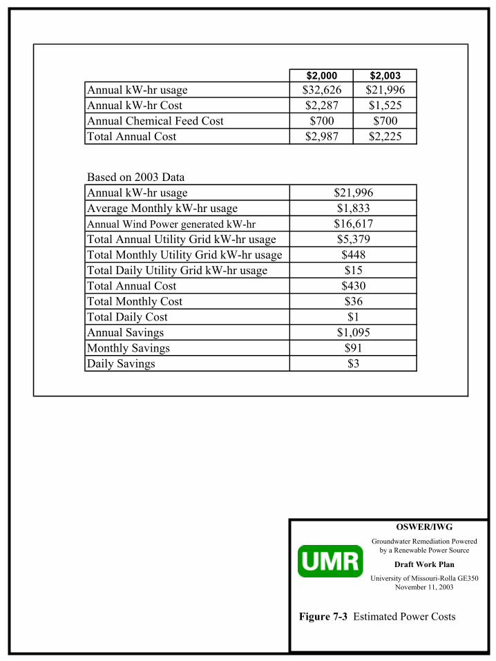
OSWER/IWGGroundwater Remediation Powered
by a Renewable Power Source
Draft Work Plan
University of Missouri-Rolla GE350 November 11, 2003
$2,000 $2,003Annual kW-hr usage $32,626 $21,996Annual kW-hr Cost $2,287 $1,525Annual Chemical Feed Cost $700 $700Total Annual Cost $2,987 $2,225
Based on 2003 DataAnnual kW-hr usageAverage Monthly kW-hr usageAnnual Wind Power generated kW-hrTotal Annual Utility Grid kW-hr usageTotal Monthly Utility Grid kW-hr usageTotal Daily Utility Grid kW-hr usageTotal Annual CostTotal Monthly CostTotal Daily Cost Annual Savings Monthly SavingsDaily Savings
$1,095$91$3
$15$430$36$1
$21,996$1,833
$5,379$448
$16,617
Figure 7-3 Estimated Power Costs

OSWER/IWGGroundwater Remediation Powered
by a Renewable Power Source
Draft Work Plan
University of Missouri-Rolla GE350 November 11, 2003
Figure 8-1 Project Schedule

Attachments
C:\CLASS\GE 350\OSWER_IWG\DRAFT WORK PLAN\TEXT.DOC\11-NOV-03\CURT ELMORE\UMR

Attachment 4-1 Installation Manual BWC EXCEL Wind Turbine
C:\CLASS\GE 350\OSWER_IWG\DRAFT WORK PLAN\TEXT.DOC\11-NOV-03\CURT ELMORE\UMR
11. Section 11 ELEVEN References


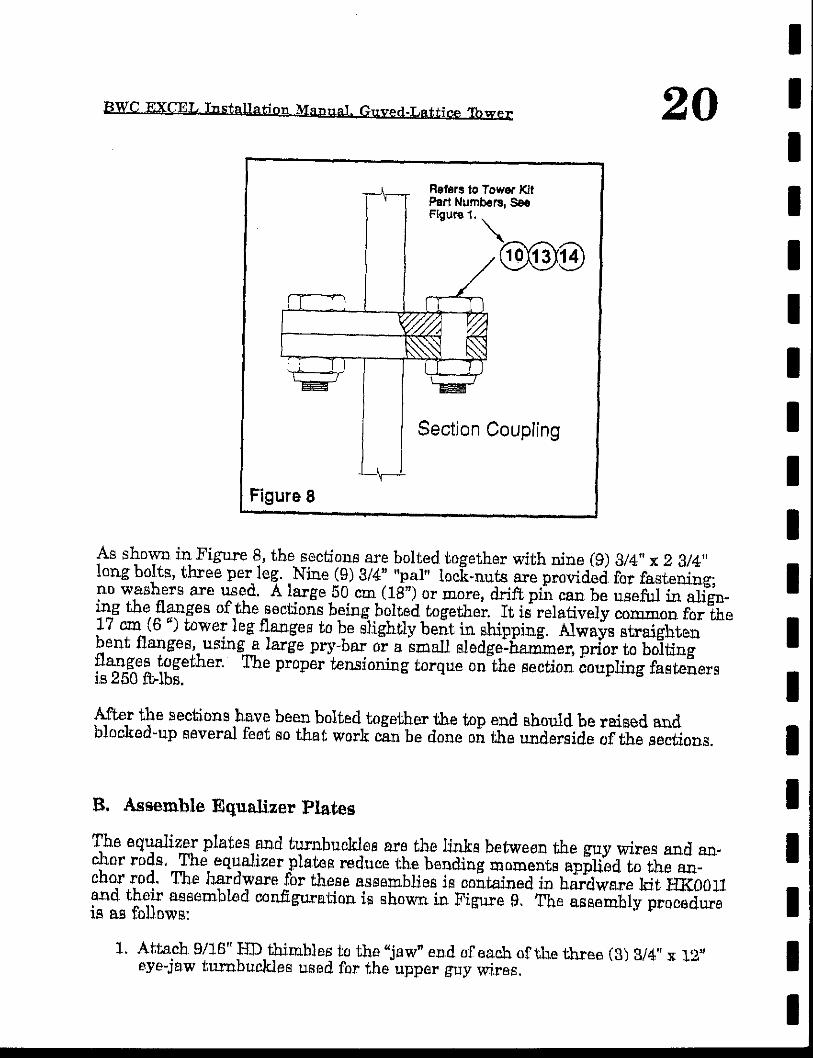
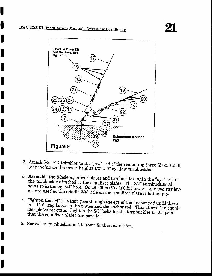


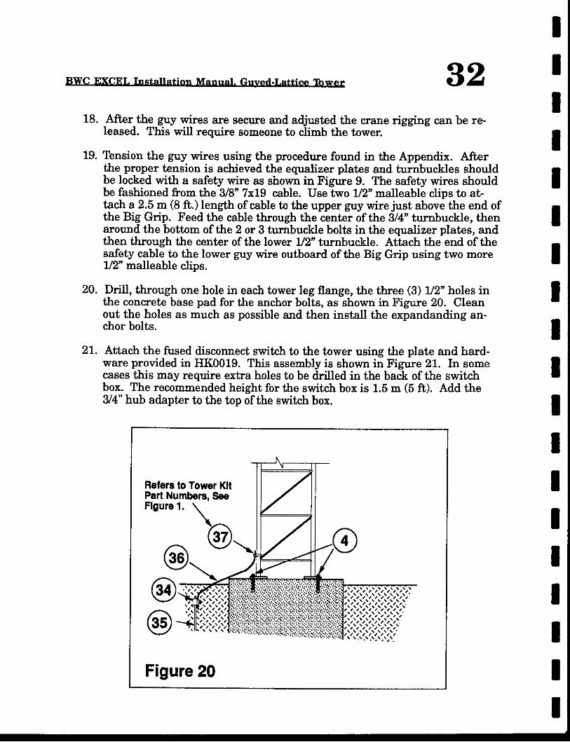
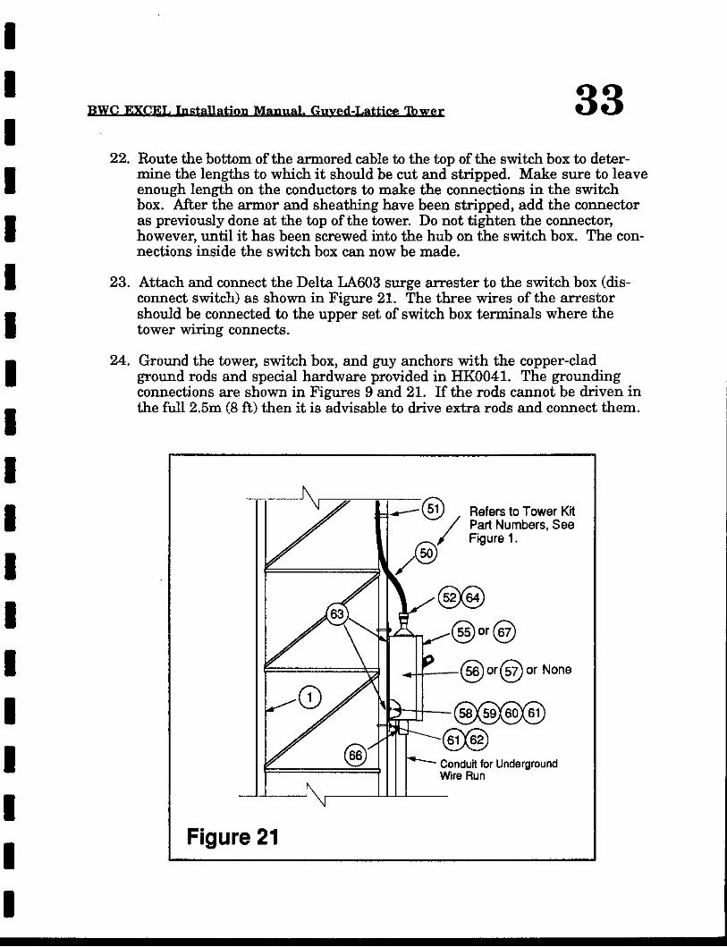


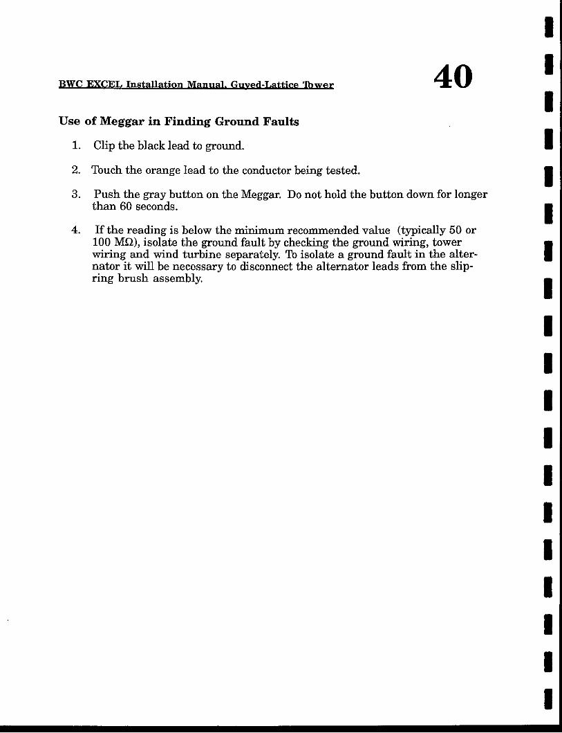


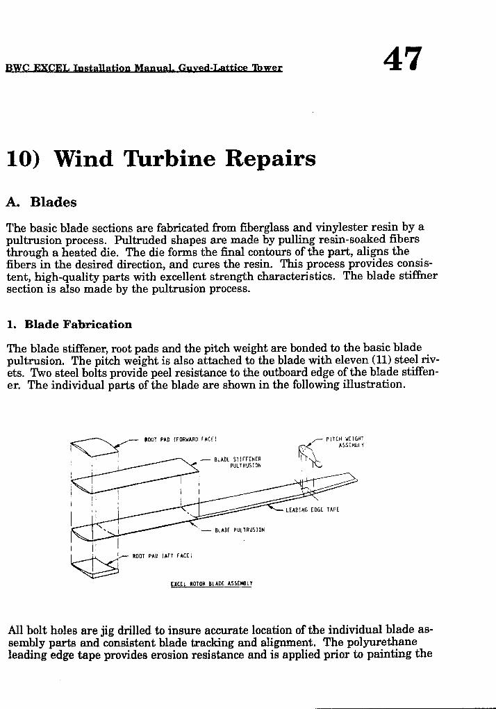


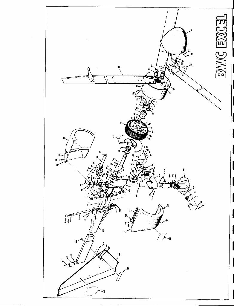


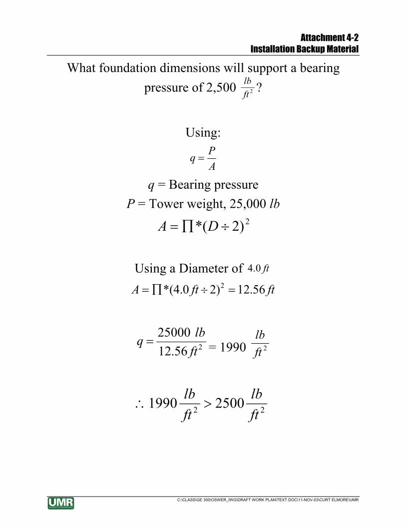
Attachment 4-2 Installation Backup Material
C:\CLASS\GE 350\OSWER_IWG\DRAFT WORK PLAN\TEXT.DOC\11-NOV-03\CURT ELMORE\UMR
What foundation dimensions will support a bearing pressure of 2,500 2ft
lb ?
Using:
APq =
q = Bearing pressure P = Tower weight, 25,000 lb
2)2*( ÷∏= DA
Using a Diameter of ft0.4 ftftA 56.12)20.4*( 2 =÷∏=
256.1225000
ftlbq = = 1990 2ft
lb
22 25001990ftlb
ftlb
>∴

Attachment 4-3 Teleconference Records
C:\CLASS\GE 350\OSWER_IWG\DRAFT WORK PLAN\TEXT.DOC\11-NOV-03\CURT ELMORE\UMR

TELECONFERENCE RECORD Subject: GE350/EPA-OSWER wind power project
Date: September 4, 2003
Participants:
• UMR
o Curt Elmore
o GE350 students
o Ron Gallagher (University of Toledo)
• Bergey Wind Systems
o Mike Bergey
Notes:
1. The Bergey website contains models that will be useful in designing the wind system. The website contains wind models, but it is better to use site-specific wind data if it is available. A 10kW Bergey wind turbine will produce 1,000 to 1,800 kW-hr per month.
2. There are two basic wind system architectures. The off grid architecture includes a set of batteries to store power, and a backup generator is often included in the system. The grid inter-tie system is typically less expensive because it does not require energy storage or a backup generator. However, the inter-tie system does not operate when there is a utility blackout. The inter-tie system “plugs in” to the “house’s” circuit board like a large appliance that produces energy (instead of consuming energy). This means that the utility meter “slows down” when the wind turbine is operational. An inter-tie system can be converted to an off grid system. The conversion cost is on the order of $10,000.
3. Lightening protection is built in to all Bergey wind systems. The anti-freeze black turbine blades are available at no extra cost.
4. Information about net metering in Nebraska can be found at dsireusa.org which is the web site for the North Carolina Solar Energy Center. Net metering may not be allowed in some locations due to safety considerations.
5. There is currently 4 to 5 weeks lead time for the delivery of 10 kW systems.
6. There is no scheduled maintenance for the turbine, but the tower requires periodic inspections described in the users manual.
• The protective tape on the blades may need periodic replacement every 6 to 10 years.
• The units have 5 yr warranties.
7. The tall guy lattice tower (120 ft) will require a 120 ft boom which is sometimes called a sign crane.

MEMO October 28, 2003 To: Dr. Curt Elmore From: Donny Nowack RE: FAA notification for 100-foot tower construction The Federal Aviation Administration (FAA), Central Regional Office, Air Traffic Division was contacted about the installation of a 100-foot tower constructed near Mead Nebraska. The division responded by stating that because the tower is less than 200 feet and over 5 miles from the closest airport (Wahoo Municipal Airport) no notification, lighting, or marking would be required. Two documents were referenced concerning notification and marking requirements: 1) Notice of Proposed Construction or Alteration, FAA Form 7460-1 (2-99) This document can be viewed or downloaded at: http://www1.faa.gov/ats/ata/ata400/part77n.pdf 2) Advisory Circular AC70/7460-1K, Obstruction Marking and Lighting.
This document can be viewed or downloaded at: http://www1.faa.gov/ats/ata/ai/circV.pdf
The area contact information is: FAA Central Regional Office Air Traffic Division, ACE-520 601 E. 12th Street Kansas City, MO 64106 Tel: 816-426-3408 or 3409

TELECONFERENCE RECORD Subject: GE350/EPA-OSWER wind power project
Date: September 26, 2003
Participants:
• Ed Louis - CENWK
• Curt Elmore – UMR
• Dave Miller – ECC
• Mike Bergey – Bergey Wind Systems
• Russ Gray - OPPD
Notes:
1. The following agenda was followed during the teleconference
a. Purpose of the wind power project
b. Estimated schedule
c. Compatibility of Bergey system and OPPD service
d. Formal coordination documents required by OPPD to connect to system
e. Status of net-metering in Nebraska
2. Mike Bergey described the single-phase power output generated by the wind system. Russ Gray said that the system would work with the current three-phase OPPD service. The existing electric meter will slow down and run backwards when the wind turbine is operating. To the best of Gray’s knowledge, Nebraska does not acknowledge net-metering.
3. Action items
a. Dave Miller will mail Elmore the historical electric consumption (OPPD bills) for the system
b. Dave Miller will ask the plant operators to examine the breaker box to make sure that there is room for one 60 amp double pole breaker. The operators will note the make and style of breaker, and the information will be transmitted to Elmore.
c. Russ Gray will confirm that the current electric meter is appropriate for the demonstration project. Gray will also determine if OPPD can donate a watt-hr meter to the project to be installed between the wind power inverter and the 60 am breaker.
d. Russ Gray will determine if OPPD has a standard interconnection contract, and he will transmit that contract to Elmore.

e. Ed Louis will handle the initial coordination with the property owner (the US Army Reserve) regarding the installation of the wind turbine system. Elmore will provide additional support as requested by Louis.

Attachment 5-1 Inspection Checklists
C:\CLASS\GE 350\OSWER_IWG\DRAFT WORK PLAN\TEXT.DOC\11-NOV-03\CURT ELMORE\UMR
Maintenance Checklist:
Inspector:
Date:
Monthly Maintenance:
Take reading of the Import Meter (M1): _________
Take reading of the Export Meter (M2): _________
Take reading of the Generation Meter (M3): _________
Ensure grass is properly short, and that the anchors are clearly visible to avoid possible collisions.
Check the heat sink and fan operations of the inverter, and ensure it is functioning properly.
Six-month Maintenance:
Check enclosure seals on all electrical components, including inverters and meters.
Check electrical connections and ensure that no frayed wires are present.
See checklist for Turbine Maintenance for detailed inspection criteria.

Attachment 5-1 Inspection Checklists
C:\CLASS\GE 350\OSWER_IWG\DRAFT WORK PLAN\TEXT.DOC\11-NOV-03\CURT ELMORE\UMR
Wind Turbine Inspection Checklist

Attachment 5-2 Maintenance Backup
C:\CLASS\GE 350\OSWER_IWG\DRAFT WORK PLAN\TEXT.DOC\11-NOV-03\CURT ELMORE\UMR

QA/QC-Section 5 1)Are references cited correctly? What references that were cited incorrectly were fixed. 2) Are all operations discussed in depth? Yes, except for the warranty information which has been modified. 3) Is all maintenance aspects discussed in depth? Yes, except for preventative maintenance which has been added 4) Is writing in third person and geared toward anyone who reads an EPA document? The writing of the document is fine. 5) Does the figure clearly represent the intended subject matter? Yes, it gives a clear picture of the basic operation of the Bergey Wind Turbine System QAQC 5.0 1. Is the operation of the turbine adequately explained?
Wind turbine operation seems to be adequately explained and is referenced properly to an attachment for further information. Make sure any direct quotes are sited.
2. Is the maintenance better as an attachment or part of the text? The inspection checklist is an attachment currently and makes sense to be that way. Are we sure that all maintenance is included?
3. Do both sections of 5 fully answer the critieria given in the outline? All points included in the outline are fully addressed and displayed in an easy to follow manner.
4. Is the attachment 5-2 clear and readable? Should the attachment in a Powerpoint format with the correct headings? Not really sure if it is currently correct.

Attachment 6-1 Power Consumption and Generation Backup
C:\CLASS\GE 350\OSWER_IWG\DRAFT WORK PLAN\TEXT.DOC\11-NOV-03\CURT ELMORE\UMR

Attachment 6-1 Power Consumption and Generation Backup
C:\CLASS\GE 350\OSWER_IWG\DRAFT WORK PLAN\TEXT.DOC\11-NOV-03\CURT ELMORE\UMR

Attachment 6-1 Power Consumption and Generation Backup
C:\CLASS\GE 350\OSWER_IWG\DRAFT WORK PLAN\TEXT.DOC\11-NOV-03\CURT ELMORE\UMR

Attachment 6-1 Power Consumption and Generation Backup
C:\CLASS\GE 350\OSWER_IWG\DRAFT WORK PLAN\TEXT.DOC\11-NOV-03\CURT ELMORE\UMR

Attachment 6-1 Power Consumption and Generation Backup
C:\CLASS\GE 350\OSWER_IWG\DRAFT WORK PLAN\TEXT.DOC\11-NOV-03\CURT ELMORE\UMR

Attachment 6-1 Power Consumption and Generation Backup
C:\CLASS\GE 350\OSWER_IWG\DRAFT WORK PLAN\TEXT.DOC\11-NOV-03\CURT ELMORE\UMR

Attachment 6-1 Power Consumption and Generation Backup
C:\CLASS\GE 350\OSWER_IWG\DRAFT WORK PLAN\TEXT.DOC\11-NOV-03\CURT ELMORE\UMR

Attachment 6-1 Power Consumption and Generation Backup
C:\CLASS\GE 350\OSWER_IWG\DRAFT WORK PLAN\TEXT.DOC\11-NOV-03\CURT ELMORE\UMR

Attachment 6-1 Power Consumption and Generation Backup
C:\CLASS\GE 350\OSWER_IWG\DRAFT WORK PLAN\TEXT.DOC\11-NOV-03\CURT ELMORE\UMR

Attachment 6-2 One-line Diagram Of Electrical Components
C:\CLASS\GE 350\OSWER_IWG\DRAFT WORK PLAN\TEXT.DOC\11-NOV-03\CURT ELMORE\UMR
One-Line Diagrams of Electrical Components. OPPD, 2003.
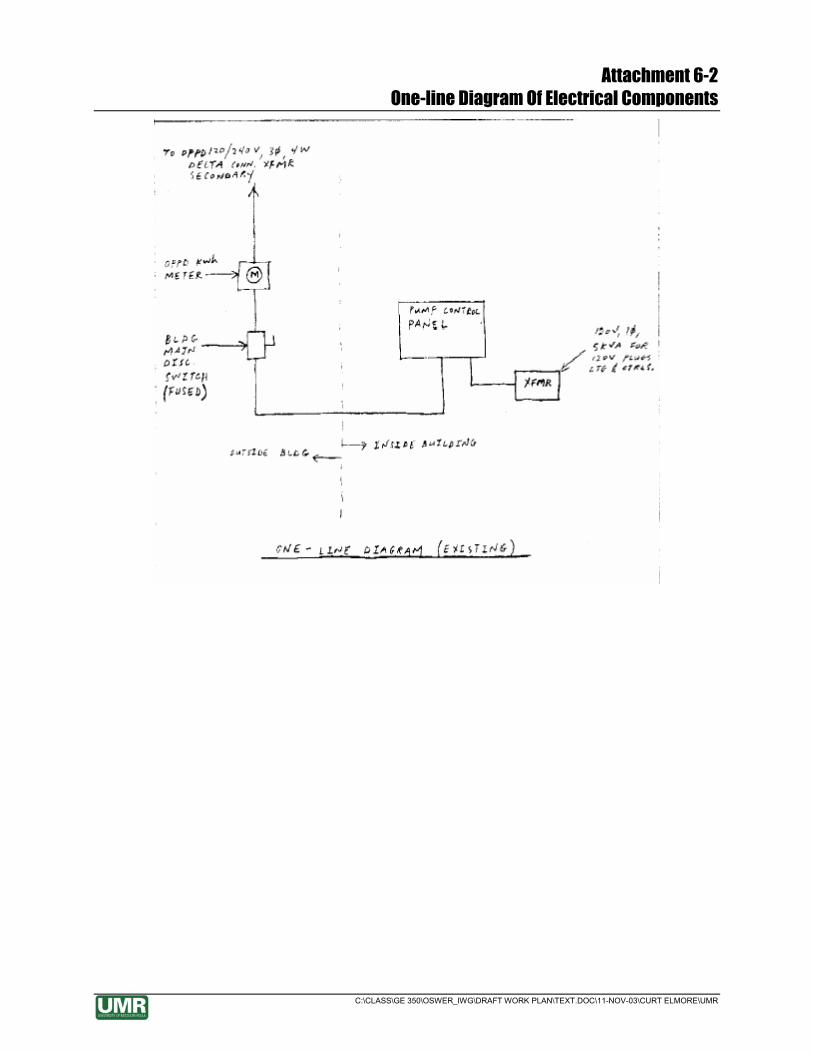
Attachment 6-2 One-line Diagram Of Electrical Components
C:\CLASS\GE 350\OSWER_IWG\DRAFT WORK PLAN\TEXT.DOC\11-NOV-03\CURT ELMORE\UMR

Attachment 6-2 One-line Diagram Of Electrical Components
C:\CLASS\GE 350\OSWER_IWG\DRAFT WORK PLAN\TEXT.DOC\11-NOV-03\CURT ELMORE\UMR

Attachment 6-2 One-line Diagram Of Electrical Components
C:\CLASS\GE 350\OSWER_IWG\DRAFT WORK PLAN\TEXT.DOC\11-NOV-03\CURT ELMORE\UMR

Attachment 6-2 One-line Diagram Of Electrical Components
C:\CLASS\GE 350\OSWER_IWG\DRAFT WORK PLAN\TEXT.DOC\11-NOV-03\CURT ELMORE\UMR

Attachment 6-3 Standard Operating Procedures For Collecting, Analyzing, And Disposing Of Samples
C:\CLASS\GE 350\OSWER_IWG\DRAFT WORK PLAN\TEXT.DOC\11-NOV-03\CURT ELMORE\UMR
Standard Operating Procedures for Collecting, Analyzing, and Disposing of Samples.
Jennifer Triplett Conference Record, October 22, 2003.
Collecting
Mark bottle with name, time, date, location (use black permanent marker) Wear gloves (change between each sampling) Water on, fill to mark Make collection field sheet (with name of person sampling, date, time, sample analyzed,
sample ID, concentration #) Put into cooler or refrigerator until time of testing Turn on to low stream Dry water droplets
Analyzing
Change gloves between analyzing of influent and effluent Using kit that has small description of how to do it Throw vials in normal trash for disposal (place in onsite dumpster) Dilution rates De-ionized water Fill vial to water line then fill the rest of the way with de-ionized water Envirometer marked up 5 minutes Calibrated daily Sample time, date, and location Maximum holding time is 24 hours to 48 hours

Attachment 6-4 System Monitoring Backup
C:\CLASS\GE 350\OSWER_IWG\DRAFT WORK PLAN\TEXT.DOC\11-NOV-03\CURT ELMORE\UMR
QA/QC Section 6
6) There was no information given regarding the monthly amount of water treated in
2003 so we found the average from the data given for 2000 and used it in calculating the
average cost per 1,000 gallons of water treated. Should we try to adjust the monthly
amount of water treated to match the data from 2000 or should we use the monthly
average for the 2000 data and assume that any flux in water treatment will be accounted
for?
There is really no way of knowing how much to adjust the amount of water treated since
data was not collected in 2003 so the best estimate that can be given is the monthly
average of the 2000 data and assume that the average will absorb the monthly flux of
treated water.
7) Do we need to attach figures showing the average monthly wind speed which was used
in calculating the power produced by the wind turbine or can we just reference the
report?
Yes, an attachment of the figure showing the average monthly wind speed should be
attached to the document so that a reference of wind speed values is included in the
document. The figure should also be referenced in the report.
8) If we attach the historical power consumption bills is it necessary to note on the
attachments that the bills are actually for the TCE well even though they are labeled
RDX?
Yes, it should probably be mentioned if the power consumption bills are attached because
the RDX well is at a different location and it would clear up any confusion about which
contaminant is being treated at the site.
9) Is the SOP easily understandable?
Yes the SOP is easy to understand for anyone who has prior knowledge of the
subject.
10) Are the reference attachment numbers correct?
Yes you have used standard procedure for referencing attachments and figures.
11) Is the rationale for determining mass removal apparent?
Yes, you have followed the structured guidelines for mass removal.
12) Who is responsible for conducting the testing?

Attachment 6-4 System Monitoring Backup
C:\CLASS\GE 350\OSWER_IWG\DRAFT WORK PLAN\TEXT.DOC\11-NOV-03\CURT ELMORE\UMR
Someone representing UMR is supposed to contact testing, if not our own person,
someone involved with the EPA.
13) Is section 6.3 readable?
Yes it is coherent and easy to read.
6.1
1. Do the numbers on figure 6-1 match the numbers from the OPPD Bills and URS spreadsheet?
From the information given, the numbers from figure 6-1 match up with the OPPD Bills and the URS spreadsheet.
2. Do the calculations look correct?
Using the numbers and the given information the calculations look correct.
3. Are the values reasonable (excluding difference between 2000 and 2003)?
They seem reasonable, even if there is a difference. The difference could have been because of a variety of outside factors.
4. Does the change from the existing line to the new proposed line seem feasible?
Yes and there seems to be very few modifications necessary.
6.2
1. Do the wind speeds match up with those in the reference?
Yes they do, though it takes some work to find the numbers in the reference.
2. Was the data entered into WindCad correctly?
Yes it was.
6.3
1. Are the numbers in the first paragraph correct according to previous sections?
Yes they appear to be correct.
2. Is the attachment clear?
Amazingly.
3. Is the entire section written in third person?
Yes.
4. Is their enough background info given to pass on knowledge of the sampling without writing out every step in the section?
The transition between providing information and referencing the SOP is smooth.
5. Is the SOP easy to follow and use? Very.

Attachment 7-1 Economic Analysis Backup
C:\CLASS\GE 350\OSWER_IWG\DRAFT WORK PLAN\TEXT.DOC\11-NOV-03\CURT ELMORE\UMR
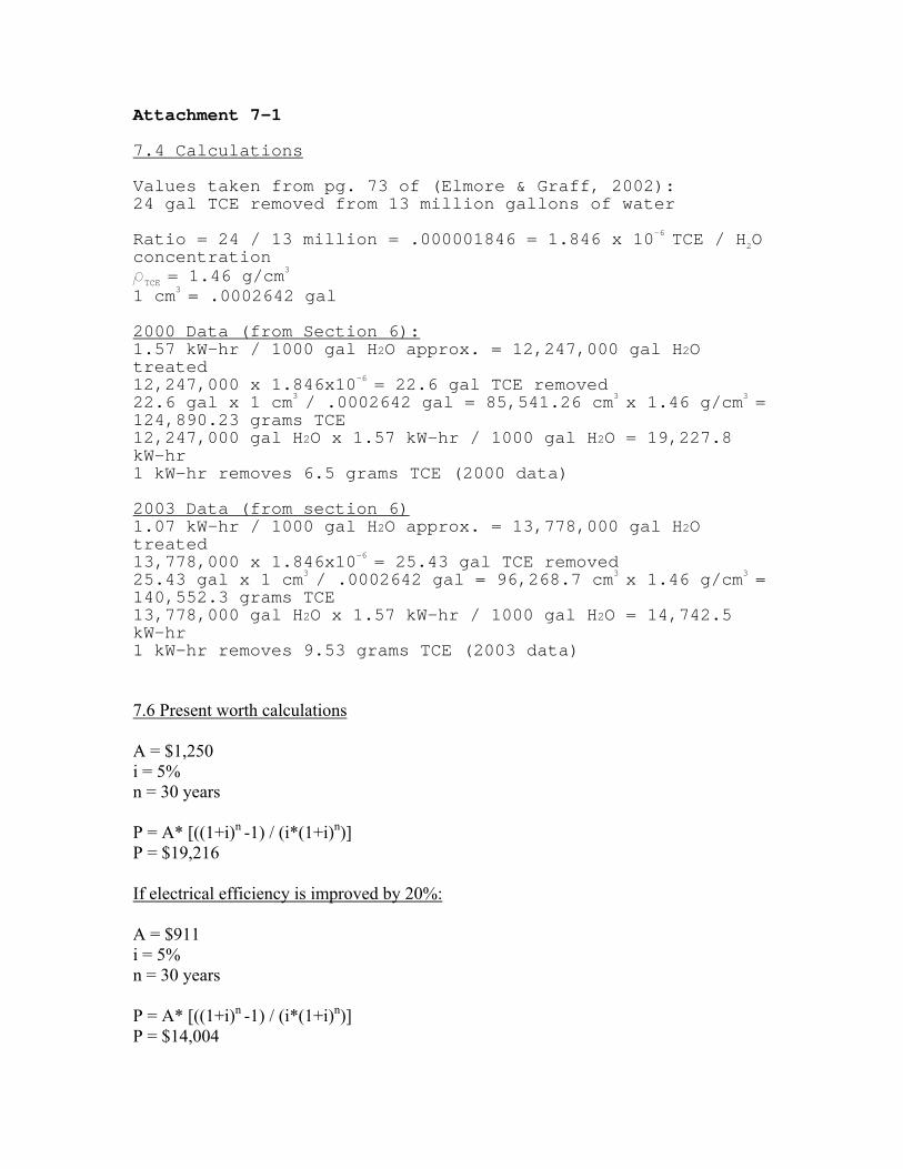
Attachment 7-1 7.4 Calculations Values taken from pg. 73 of (Elmore & Graff, 2002): 24 gal TCE removed from 13 million gallons of water Ratio = 24 / 13 million = .000001846 = 1.846 x 10⁻⁶
TCE / H2O concentration ρTCE = 1.46 g/cm
3 1 cm3
= .0002642 gal 2000 Data (from Section 6): 1.57 kW-hr / 1000 gal H2O approx. = 12,247,000 gal H2O treated 12,247,000 x 1.846x10-6
= 22.6 gal TCE removed 22.6 gal x 1 cm3
/ .0002642 gal = 85,541.26 cm3 x 1.46 g/cm3
= 124,890.23 grams TCE 12,247,000 gal H2O x 1.57 kW-hr / 1000 gal H2O = 19,227.8 kW-hr 1 kW-hr removes 6.5 grams TCE (2000 data) 2003 Data (from section 6) 1.07 kW-hr / 1000 gal H2O approx. = 13,778,000 gal H2O treated 13,778,000 x 1.846x10-6
= 25.43 gal TCE removed 25.43 gal x 1 cm3
/ .0002642 gal = 96,268.7 cm3 x 1.46 g/cm3
= 140,552.3 grams TCE 13,778,000 gal H2O x 1.57 kW-hr / 1000 gal H2O = 14,742.5 kW-hr 1 kW-hr removes 9.53 grams TCE (2003 data) 7.6 Present worth calculations A = $1,250 i = 5% n = 30 years P = A* [((1+i)n -1) / (i*(1+i)n)] P = $19,216 If electrical efficiency is improved by 20%: A = $911 i = 5% n = 30 years P = A* [((1+i)n -1) / (i*(1+i)n)] P = $14,004
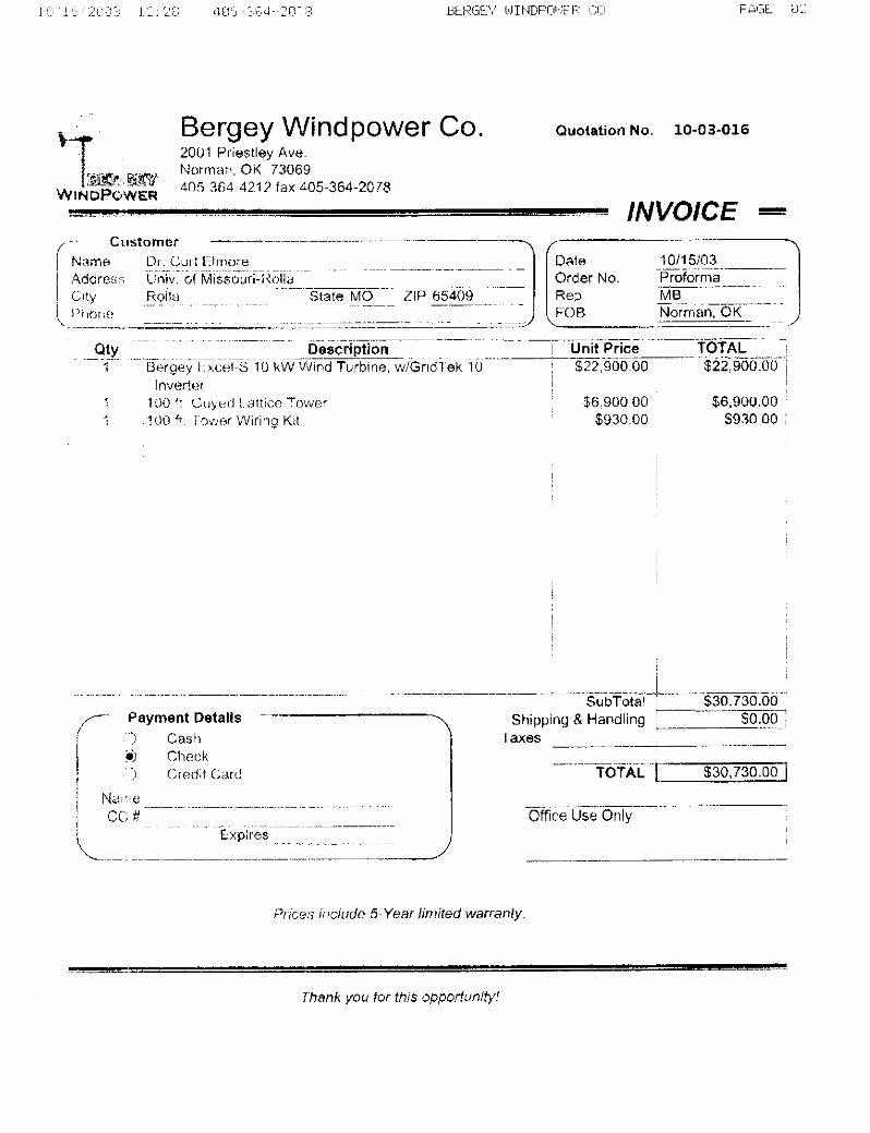

Section 7 QA/QC
1. Is grammar and spelling correct? Yes, the grammar and spelling is correct and what was not was fixed. 2. Are references properly cited? All references to figures and facts are properly cited at the end of section 7. 3. Are figures properly ordered? All new figures are properly put in order of reference in section 7, and origins of figures are referenced. 4. Does all font and size match up in section 7? All subsections were put together in matching font and size. 5. Are all spreadsheets put as attachments? Yes, all new spreadsheets for this section are not put in the base of the document, but were attached separately. 6. Was the subcontracting properly recorded? All subcontracting price estimates were recorded with the date, estimator company name and contacting telephone number. The name of the individual contacted was not attached in any section. 7. Does data in section 7, match up with data in previous sections? All data used in section seven is the most up to date data available. 8. Is the wind turbine cost estimate accurate? The wind turbine cost estimate, is quoted from Bergey website information. The actual bid number has not been given yet, due to procurement delays. 9. Is delivery included in Bergey’s wind turbine price? According to Dr. Elmore the final Bergey wind turbine price, includes shipment and delivery of the wind turbine. 10. Do we pay the ECC for meter readings? No, we do not and that is not figured in annual costs of O&M of the wind turbine. 11. Is data from OPPD bills accurate? The data from the OPPD are as accurate as we can get on power usage, even though there is probably some human error in a few months’ readings, so some of our data may be off, based on the OPPD bills. 12. Are the values reasonable? The values match up with the information provided.

13. Is the table clear? The table corresponds with the example given and is clear. 14. Have the numbers been calculated correctly? Yes. 15. Does the text explain the calculations? It is a little short, but to the point. Further explanation would be an over kill. Additional Comments: Make sure that if you use information from previous sections, use the reconciled document. Peer Reviewed by: Ana Mora and Barb Porter Date: November 2, 2003

Attachment 8-1 Schedule Backup
C:\CLASS\GE 350\OSWER_IWG\DRAFT WORK PLAN\TEXT.DOC\11-NOV-03\CURT ELMORE\UMR

Section 8 Peer Review Questions BLUE Q1. Is the schedule realistic? Do the dates and times seem reasonable on the schedule? A1. Yes. Float has been given for the contract procurements and foundation cure time. The only foreseeable lag resides in the procurements and the ability of a Bergey Representative on the specified dates of construction in the Scope of Work. Q2. Does the schedule include delivery times? A2. Yes. Two deliveries will be made to the same address attached. Q3. Are any references used? If so, are they cited correctly? A3. Only one – Gridtek 10 referenced nicely from the Bergey web site. Q4. Is the format easily decipherable? A4. A Gantt chart is commonplace in industry. The template provided is blurry, but decipherable. Q5. Can Professor Gallagher stake the site prior to date desired? A5. UMR and Professor Gallagher have agreed that he will stake the site on October 21, 2003. Thanks to Professor Gallagher. Q6. Does Bergey allow tower to be erected less than two weeks after foundation is poured? A6. Manual suggests two weeks. Float has been given so that installation is not done until 20 days after second day of foundation contraction. Q7. Is the final day on the schedule within the allotted time for this project? A7. December 1 is well within the target dates allotted in the original proposal. December 20, 2003 – UMR graduation – was the deadline for a running system. RED 1. Is there enough time for the concrete to cure to its maximum strength? 2. Is more time needed for the installation of the wind turbine and tower? 3. Are the forms for the foundation able to be moved at the time specified? 4. Have all the aspects of the project been covered in the schedule? 5. Does the schedule match construction/subcontracting plan? 6. Does the organization of the work seem reasonable? 7. Is the overall scale feasible?
Answers: 1. Depending on temperatures of the concrete and how wet the concrete initially is will give you different cure times. On average it is around a month, so the 28 days should give sufficient time to cure to its maximum strength. 2. It should be enough time, but it also depends on how many hours the subcontractor is willing to put in each working day. 3. It will depend on the concrete and cure time. 4. It looks like it. 5. Will need to see the construction/subcontract plan to determine. 6. Yes. 7. It should be and it corresponds to the time that we have in the semester.

Attachment 9-1 Wind Turbine System Procurement
C:\CLASS\GE 350\OSWER_IWG\DRAFT WORK PLAN\TEXT.DOC\11-NOV-03\CURT ELMORE\UMR
Attachment 9-1: Wind Turbine System Procurement, Bergey Windpower Company, Inc.
9.1.1 Introduction
The Environmental Protection Agency (EPA) promotes high efficiency systems to remediate groundwater contamination. The use of a Renewable Energy Source, such as a wind-powered turbine generator, will further research in to the design of groundwater remediation systems that operate in cooperation with the renewable energy source. This project consists of a Groundwater Circulation Well (GCW), located at the former
Nebraska Ordnance Plant (NOP) near Mead, Nebraska, and the installation of a 10kW Grid Inter-tie System. Currently, the GCW operates continuously on the local electric power grid. The coupling of the wind turbine through the Grid Inter-tie System will generate power to the system rather than draining power. If the GCW energy consumption requirements are in excess of the energy produced by the 10kW wind turbine, the Grid Inter-tie System allows for additional power to come from the utility grid. However, if the power needs of the GCW are met by the wind turbine, the utility grid will not be used. The Grid Inter-tie System allows the GCW to operate continuously as designed. This project may lead to future groundwater remediation designs that operate intermittently with the energy provided by the wind power system.
9.1.2 Objective
The overall objective of this project is the demonstration of the use of a renewable energy source, specifically wind power, to power a groundwater remediation system. The demonstration includes of the installation of a commercial wind turbine. The turbine, placed on a 100 foot high tower, is connected to the site utility grid via a Grid Inter-tie System. The construction of the tower is divided into three phases of work, including (1) foundation and anchor construction, (2) tower construction, and (3) installation of electrical components.
9.1.3 Scope of Work
Official procurement of 10 kW wind turbine system is required before the commencement of construction. Delivery of foundation materials is expected immediately following procurement of the wind turbine system. The expected materials consist of a sufficient quantity of guy wire for the 100-foot guyed lattice tower with a 50-foot radius, three (3) oval eye anchor rods, one (1) ¾ inch by 12 inch all thread pier pin, and all other hardware and materials necessary for foundation completion. Delivery of the remaining wind turbine components, including a 100-foot tower, 10kW wind turbine, and tower wiring kit, is expected by December 1, 2003. A Bergey Windpower installation technician, with comprehensive experience in the assembly, installation and start up of the wind turbine system, is expected to accompany the tower delivery, to perform quality control and provide assistance for the system installation. The system

Attachment 9-1 Wind Turbine System Procurement
C:\CLASS\GE 350\OSWER_IWG\DRAFT WORK PLAN\TEXT.DOC\11-NOV-03\CURT ELMORE\UMR
installation will include tower construction, tower and turbine connection, tower erection, inverter installation, electrical connections, and initial testing of power generation. Response is required prior to October 27, 2003.
System components delivery address:
Environmental Chemical Corporation
905 County Road 6
Ashland, NE 68003
(402) 944-6013
(402) 944-6018 (fax)
Bergey Technical Support Requirements:
• Official procurement of 10 kW wind turbine system • Delivery of foundation materials by November 3, 2003 • Tower, turbine, Grid Inter-tie System, and tower wiring kit delivery on December 1, 2003 • On-site guidance during erection, placement, and testing of turbine and power generation on specified dates:
• December 2-4 for Tower installation and electrical hookup oversight • Response is required prior to October 27, 2003

Attachment 9-2 System Construction and Installation
C:\CLASS\GE 350\OSWER_IWG\DRAFT WORK PLAN\TEXT.DOC\11-NOV-03\CURT ELMORE\UMR
Attachment 9-2: System Construction and Installation, M.E. Collins Company
9.2.1 Objective
The overall objective of this project is the demonstration of the use of a renewable energy source, specifically wind power, to power a groundwater remediation system. The demonstration will consist of the installation of a commercial wind turbine. The turbine will be placed on a 100 foot high tower and then be connected to the site electrical system. The construction of the tower is divided into three phases of work, including (1) foundation and anchor construction, (2) tower construction, and (3) installation of electrical components.
9.2.2 Scope of Work
The project is organized into three phases.
Phase I: Site Preparation and Foundation Installation
On or about October 21, 2003, the locations of the tower anchors and foundations will be staked by a UMR representative. It is the responsibility of the subcontractor to make sure that these markings agree with the design plans. Once the site has been completely prepared, utility clearance must be gained and documented by the subcontractor. For this and the remainder of the project, the subcontractor will comply with National Electric Code (NEC), OSHA, and all other applicable requirements and codes.
The anchors, anchor accessories, and guy wires will be delivered to:
Environmental Chemical Corporation
905 County Road 6
Ashland, NE 68003
The contractor will provide all necessary equipment, tools, concrete, and reinforcing steel for the construction of the tower anchors and base pad. Excavation safety must be followed according to any and all OSHA standards. Care should be taken to protect the concrete foundations from temperatures below 40 degrees Fahrenheit during the minimum fourteen day curing process. For cold weather concrete placement, thermal blankets, or another approved method, should be used to cover the curing concrete sections. Base pad and subsurface guy anchor construction is described in detail on in the enclosed attachments. The contractor will also construct two (2) bollards on the parking lot guy anchor, see the enclosed Site Map. Bollards should be placed at

Attachment 9-2 System Construction and Installation
C:\CLASS\GE 350\OSWER_IWG\DRAFT WORK PLAN\TEXT.DOC\11-NOV-03\CURT ELMORE\UMR
least two feet in the ground with four feet above ground, constructed from 6 inch steel pipe filled with concrete. The bollards should be installed so as to protect the guy anchor and wiring from damage from vehicle traffic.
Construction Contractor Responsibilities:
• Verify site survey • Obtain and document utility clearance • Provide concrete, forming materials, reinforcing materials, and bollard materials • Construct foundation, anchors, and bollards • Provide excavation safety according to any and all OSHA regulations
UMR Responsibilities:
• Stake the locations of the tower base pad and anchors • Provide guy wire, three (3) oval eye anchor rods, one (1) ¾ inch by 12 inch all thread
pier pin, and all applicable hardware
Phase II: Assembly and Installation of Wind Turbine System
The contractor will provide all equipment, materials, and labor for receiving materials, tower assembly, tower erection, and guy wire tensioning. Tower assembly is described in detail on pages 18 to 33 of the Bergey Installation Manual, which was transmitted to the contractor on October 10, 2003. A Bergey representative will provide additional support. Upon delivery, all materials must be inventoried and checked for signs of damage. Any damage must be noted as precisely as possible and must include photographs. In the event of a problem, UMR must be notified as soon as possible so that replacement parts can be sent. The blade box, electronics box, and powerhead will be left in packaging and covered with a waterproof material until ready for installation. Tower sections are approximately 550 pounds each. Handling of these sections during assembly should be done with heavy equipment or a minimum of 4 people. Erection of the tower will require a light duty crane capable of lifting at least 8,000 pounds to a height of 100 feet. Guy wires will be attached to the tower and tensioned according to the Appendix of the Bergey Installation Manual. Tower delivery will take place December 1, 2003 and with construction completion from December 2 to 3, 2003.
Construction Contractor Responsibilities:
• Receive, inventory, and unload materials • Assemble tower • Erect tower, provide crane • Install guy wires

Attachment 9-2 System Construction and Installation
C:\CLASS\GE 350\OSWER_IWG\DRAFT WORK PLAN\TEXT.DOC\11-NOV-03\CURT ELMORE\UMR
• Provide proper fall safety for workers
UMR Responsibilities:
• Provide tower materials
Phase III: Installation of Electrical Components The construction contractor will provide a licensed electrician to install and connect the electrical components. The installation of electrical components is described in detail on pages 34 to 36 of the Bergey installation manual. Wiring will conform to the U.S. NEC and any other state and local codes. System implementation requires a 150 foot power cable of #6 AWG 13.3 mm2 with a 34 amp maximum 3-phase amperage. The system will run through a 35 amp fuse. Wiring must be rated for 600 V AC. The three-conductor wire run between the tower and the control unit will be enclosed in conduit and run underground. Conduit shall be watertight electrical grade PVC plastic and will be buried at least 2 feet below the ground surface. Watertight connectors will be used on each end of the conduit. The wire from the tower will be run into a small portable building. Time of installation for the conduit and wiring is left to the discretion of the contractor, as long as it is completed prior to final system setup. The construction contractor will provide the 230V circuit box, the 60 amp dual pole circuit breaker, wiring, and conduit necessary to complete the installation. Installation of electrical components will be completed by December 4, 2003. The contractor is responsible for the delivery of the materials to the site.
Construction Contractor Responsibilities:
• Receive and unload materials • Bury cable • Provide 230V circuit box, 60 amp dual pole circuit breaker, power cable, and conduit
• Install electrical components
UMR Responsibilities:
• Provide the GridTek 10 power inverter • Provide watt-hr meter

OSWER/IWGGroundwater Remediation Powered
by a Renewable Power Source
Draft Work PlanUniversity of Missouri-Rolla GE350
September 29, 2003
Design Changes: Base Pad
Based on Bergey 1999
Design ChangesBase Pad

OSWER/IWGGroundwater Remediation Powered
by a Renewable Power Source
Draft Work PlanUniversity of Missouri-Rolla GE350
September 29, 2003
Design ChangesTower Connection
Based on Bergey 1999
Design Changes: Tower Connection

OSWER/IWGGroundwater Remediation Powered
by a Renewable Power Source
Draft Work PlanUniversity of Missouri-Rolla GE350
September 29, 2003
Guy Wire Anchor Construction
Guy Wire Anchor Construction
Based on Bergey 1999

Attachment 9-3 Construction Plan Backup
C:\CLASS\GE 350\OSWER_IWG\DRAFT WORK PLAN\TEXT.DOC\11-NOV-03\CURT ELMORE\UMR

Section 9 Peer Review Questions BLUE Q2. Does the system description need more detail concerning individual components such as transducers and electrical devices? A2. No. That information can be obtained from Bergey Windpower Systems if necessary. Q3. Do we need to include any cost estimates or information regarding the budget in the proposal? A3. The outline reads Section 9 as Construction Plan. Section 7 will cover budget issues. Q4. Did we include a request for Bergey to supervise the installation of the turbine? A4. Bergey Scope of Work is attached. Q5. Do the page numbers referenced in the scopes of work correspond to the appropriate portions of the Bergey installation manual? A5. All material is referenced according to the document page number. Q6. Do the scopes of work adequately summarize the installation process detailed in the Bergey installation manual? A6. Yes, or they simply say follow instructions provided in the attached document. Q7. Are the outlined responsibilities for each group correct? A7. Scopes of work outline contract work structure and Bergey work structure. Q8. Are the dates for each work phase consistent with the schedule? A8. All work outlines are consistent with the schedule provided. Scopes of Work: Q1. Are the attachments referenced correctly stated? A1. Reference to the schedule is stated where necessary. Q2. Are the materials to be delivered correctly stated? A2. As stated in the foundation scope of work, foundation materials include anchors, anchor accessories, and guy wires will be delivered to address provided. Q3. Does the timing of delivery items from Bergey correspond with the staging of construction? A3. Stepped construction tasks are outlined and proper dates and lag times are provided. Q4. Is the scope of work in an easily readable format? Are the tasks plainly stated? A4. Proper technical writing and bullet formats were used on the scopes of work to allow quick reference and ease of use. Q5. Is the delivery location(s) correct? A5. The delivery address has been provided by the U.S. Army Corps of Engineers Reserve Base where the GCW is located. All deliveries will be made to the same address with additional transport to the specific site provided by the contractor. Section 9.1 1. Are the dates of delivery correct? The dates of delivery are consistent with what is currently provided in the scheduling section. 2. Is the shipping address correct? The shipping address has not been provided in the section or by the instructor, this information needs to be obtained.

3. Is the SOW in Person? There were many instances that 1st person was used and those instances have been changed. 4. Does the background information supply enough information for Bergey since he already understands the system? You may need to tell where you got that information because Bergey probably doesn’t have everything memorized. It is more for reference and backing up the information then for Bergey himself. 5. Which system do we want to buy? The model number of the system needs to be found and decided on. 6. Is it clear as to what we are asking Bergey to give us a price quote on? We need determine what Bergey is specifically responsible for and make the corrections within the SOW. 9.2 QA/QC 1) Will the following activities, if completed, result in an operational system? 2) Are the steps provided in an order that would benefit the install process? 3) Is enough detail paid, or are further/detailed explanations required? Answers: 1) That is yet to be determined, but from the available information, it seems that by following these activities, the system should operate properly. 2) It seems that by performing these steps in the order provided will ultimately lead to an operating system. It is important to note that the subcontractor has flexibility in performing these tasks. These steps provided are serving as a basis of operation, not as a required method. 3) There is sufficient detail provided. As with question 2, too much detail could lead to