draft tender document for eshilakwe irrigation …€¦ · ppda 2015 public procurement and...
TRANSCRIPT

REPUBLIC OF KENYA
MINISTRY OF AGRICULTURE, LIVESTOCK, FISHERIES AND
IRRIGATION
STATE DEPARTMENT FOR IRRIGATION
NATIONAL WATER HARVESTING FOR IRRIGATION PROGRAM
TENDER DOCUMENT
DRILLING, EQUIPPINGOF A BOREHOLE, CONSTRUCT
ELEVATED STEEL TANK AND 0.125 ACRE DEMONSTRATION GREEN HOUSE UNDER THE NATIONAL WATER HARVESTING IRRIGATION PROJECT AT ESHILAKWE PRIMARY SCHOOL,
NAVOKHOLO CONSTITUENCY, KAKAMEGA COUNTY
TENDER NO. MALFI/SDI/OT/005/2018-2019
TABLE OF CONTENTS SECTION I: INVITATION TO TENDER.......................................................4 SECTION II: INSTRUCTIONS TO TENDERER......................................................... 5 SECTION III: APPENDIX TO INSTRUCTIONS TO TENDERERS.......................... 22 SECTION IV: GENERAL CONDITIONS OF CONTRACT...................................... ..28 SECTION V: CONDITIONS OF CONTRACT PART II (SCC)................................ ..29 SECTION VI: SPECIFICATIONS................................................................................ 55 SECTION VII: BILL OF QUANTITIES …….............. .................................................154 SECTION VIII: DRAWINGS………… .......................................................................285 SECTION IX: STANDARD FORMS .......................................................................... 310
ABBREVIATIONS AND ACRONYMS CDS Contract Data Sheet GCC General Conditions of Contract IFT Invitation for Tender ITT Instruction to Tenderers PE Procuring Entity PM Project Manager PPDA 2015 Public Procurement and Disposal Act, 2015 PPDR 2006 Public Procurement and Disposal Regulations, 2006 PPOA Public Procurement Oversight Authority STD Standard Tender Documents SOR Statement of Requirements SP Service Provider TDS Tender Data Sheet VAT Value Added Tax

SECTION I: INVITATION TO TENDER
State Department of Irrigation now invites sealed Tenders from eligible contractors who should meet the following minimum conditions. i. Registered with NCA 7 Water Works and above ii. Firms copy of Certificate of registration as a BoreholeDrilling, Equipping and Servicing contractors with the Ministry of Water and Sanitation under class C and above. iii. Evidence of past experience in similar works of same nature and complexity iv. Proof of Legal existence. v. Copies of valid tax compliance, VAT and PIN certificates. vi. Adequate plant and equipment, professional and technical staff. Scope of the Works The works involves but is not limited to the following ing minimum conditions.
o Drilling, Development and Test pumping of borehole o Equiping of borehole o Construction of pump house and water kiosk o Contraction of elevated steeltanks and water conveyance piping o Construction of 2No. Green Houses Interested eligible Contractors may obtain further information and inspect the tender documents at the State Department for Irrigation offices located at Maji House,Ngong
Road, at the procurement department 1st floor room 145 during normal working hours. A Complete set of tender documents can be down loaded from the Ministry’s website www.kilimo.go.ke or www.supplier.treasury.go.ke The completed tender document in plain sealed envelope clearly marked “Tender No.MALFI/SDI/OT/007/2018-2019- Tender for drilling and Equipping of a borehole and construction of elevated steel tank for Eshilakwe Primary School, Navokholo Constituency, Kakamega County PRINCIPAL SECRETARY, STATE DEPARTMENT OF IRRIGATION, MINISTRY OF AGRICULTURE, LIVESTOCK, FISHERIES AND IRRIGATION P O BOX 30028 – 00100 NAIROBI And be deposited in Tender Box situated on the Ground Floor at Ministry of Water & Sanitation Offices so as to be received on or before Date 31st January 2019, 12.00 Noon. Prices quoted should be inclusive of all taxes and shall remain valid for 120 days from the closing date of the tender. The tenders will be opened immediately thereafter in Board room 6th floor of Maji House in presence of bidders or their representatives who may wish to attend. Selection of the Bidders will be in accordance with the Pulic Procurement and Asset Disposal Act, 2015.

SECTION II. INSTRUCTIONS TO TENDERERS
Table of Clauses Contents A. GENERAL .................................................................................................................... 8 1. Definitions ..................................................................................................................... 8 2. Eligibility and Qualification Requirements ................................................................. 8 3. Cost of Tendering .......................................................................................................... 9 4. Site Visit....................................................................................................................... 10 B: TENDER DOCUMENTS ........................................................................................... 10 5. Tender Documents ...................................................................................................... 10 6. Inquiries by Tenderers ................................................................................................ 11 7. Amendment of Tender Documents ............................................................................. 11 C. PREPARATION OF TENDERS ................................................................................ 11 8. Language of Tender .................................................................................................... 11 9 Documents Comprising the Bid .................................................................................. 11 10. Tender Prices .............................................................................................................. 12 11 Currencies of Tender and Payment ........................................................................... 13 12 Tender Validity ........................................................................................................... 13 13 Tender Security ........................................................................................................... 14 14 No alternative offers .................................................................................................... 14 15. Pre-tender Meeting ..................................................................................................... 14 16 Format and Signing of Tenders .................................................................................. 15 D. SUBMISSION OF BIDS ............................................................................................. 15 17 Sealing and Marking of Bids ...................................................................................... 15 18 Deadline for Sub-mission of Bids................................................................................ 16 19 Modification and Withdrawal of Bids ........................................................................ 16 E. TENDER OPENING AND EVALUATION .............................................................. 17

20 Tender Opening .......................................................................................................... 17 21. Process to Be Confidential .......................................................................................... 17 22 Clarification of Tenders .............................................................................................. 17 23 Determination of Responsiveness ............................................................................. 18 24 Correction of Errors .................................................................................................. 18 25 Conversion to Single Currency ................................................................................... 19 26 Evaluation and Comparison of Bids ........................................................................... 19 F. AWARD OF CONTRACT ......................................................................................... 20 27 Award Criteria ............................................................................................................ 20 28 Notification of Award................................................................................................. 21 29 Performance Guarantee .............................................................................................. 21 30 Advance Payment ........................................................................................................ 22 APPENDIX TO INSTRUCTIONS TO TENDERERS ..................................................... 23
Instructions to Tenderers A. GENERAL
1. Definitions a. “Tenderer” means any persons, partnership firm or company submitting a sum or sums in the Bills of Quantities in accordance with the Instructions to Tenderers, Conditions of Contract Parts I and II, Specifications, Drawings and Bills of Quantities for the work contemplated, acting directly or through a legally appointed representative. b. “Approved tenderer” means the tenderer who is approved by the Employer. c. Any noun or adjective derived from the word “tender” shall be read and construed to mean the corresponding form of the noun or adjective “bid”. Any conjugation of the verb “tender” shall be read and construed to mean the corresponding form of the verb “bid.” d. “Employer” means a Central Government Ministry, Local Authority, State Corporation or any other Public Institution. 2. Eligibility and Qualification Requirements 2.1 Eligibility requirements This invitation to tender is open to all tenderers who are qualified as stated in the appendix. 2.2 Qualifications Requirements To be qualified for award of Contract, the tenderer shall provide evidence satisfactory to the Employer of their eligibility under Sub clause 2.1. above and of their capability and adequacy of resources to effectively carry out the subject Contract. To this end, the tenderer shall be required to update the following information already submitted during prequalification:- (a) Details of experience and past performance of the tenderer on the works of a similar nature and details of current work on hand and other contractual commitments. (b) The qualifications and experience of key personnel proposed for administration and execution of the contract, both on and off site. (c) Major items of construction plant and equipment proposed for use in carrying out the Contract. Only reliable plant in good working order and suitable for the work required of it shall be shown on this schedule. The tenderer will also indicate on this schedule when each item will be available on the Works. Included also should be a schedule of plant, equipment and material to be
imported for the purpose of the Contract, giving details of make, type, origin and CIF value as appropriate. (d) Details of sub-contractors to whom it is proposed to sublet any portion of the Contract and for whom authority will be requested for such subletting in accordance with clause 4 of the Condition of Contract. (e) A draft Program of Works in the form of a bar chart and Schedule of Payment which shall form part of the Contract if the tender is accepted. Any change in the Program or Schedule shall be subjected to the approval of the Engineer. (f) Details of any current litigation or arbitration proceedings in which the tenderer is involved as one of the parties. 2.3 Joint Ventures Tenders submitted by a joint venture of two or more firms as partners shall comply with the following requirements:- (a) The tender, and in case of a successful tender, the Form of Agreement, shall be signed so as to be legally binding on all partners (b) One of the partners shall be nominated as being in charge, and this authorization shall be evidenced by submitting a power of attorney signed by legally authorized signatories of all the partners (c) The partner in charge shall be authorized to incur liabilities and receive instructions for an on behalf of any and all partners of the joint venture and the entire execution of the Contract including payment shall be done exclusively with the partner in charge. (d) All partners of the joint venture shall be liable jointly and severally for the execution of the Contract in accordance with the Contract terms, and a relevant statement to this effect shall be included in the authorization mentioned under (b) above as well as in the Form of Tender and the Form of Agreement (in case of a successful tender) (e) A copy of the agreement entered into by the joint venture partners shall be submitted with the tender. 3. Cost of Tendering 3.1 The Tenderer shall bear all costs associated with the preparation and submission of his tender and the Employer will in no case be responsible or liable for those costs, regardless of the conduct or outcome of the tendering process. 3.2 The price to be charged for the tender document shall not exceed Kshs.1,000/= 3.3 The procuring entity shall allow the tenderer to view the tender document free of charge before purchase.
4. Site Visit 4.1 The tenderer is advised to visit and examine the Site and its surroundings and obtain for himself on his own responsibility, all information that may be necessary for preparing the tender and entering into a contract. The costs of visiting the Site shall be the tenderer’s own responsibility 4.2 The tenderer and any of his personnel or agents will be granted permission by the Employer to enter upon premises and lands for the purpose of such inspection, but only upon the express condition that the tenderer, his personnel or agents, will release and indemnify the Employer from and against all liability in respect of, and will be responsible for personal injury (whether fatal or otherwise), loss of or damage to property and any other loss, damage, costs and expenses however caused, which but for the exercise of such permission, would not have arisen. 4.3 The Contractor may conduct a site visit at his own cost. B: TENDER DOCUMENTS 5. Tender Documents 5.1 The Tender documents comprise the documents listed here below and should be read together with any Addenda issued in accordance with Clause 7 of these instructions to tenderers. a. Form of Invitation for Tenders b. Instructions to Tenderers c. Form of Tender d. Appendix to Form of Tender e. Form of Tender Surety f. Statement of Foreign Currency Requirements g. Tender and Confidential Business Questionnaires h. Details of Sub contractors i. Schedules of Supplementary Information j. General Conditions of Contract – Part I k. Conditions of Particular Application – Part II l. Specifications m. Bills of Quantities n. Drawings o. Declaration Form 5.2 The tenderer is expected to examine carefully all instructions, conditions, forms, terms, specifications and drawings in the tender documents. Failure to comply with the requirements for tender submission will be at the tenderer’s own risk. Pursuant to clause 22 of Instructions to Tenderers, tenders which are not substantially responsive to the requirements of the tender documents will be rejected. 5.3 All recipients of the documents for the proposed Contract for the purpose of submitting a tender (whether they submit a tender or not) shall treat the details of the documents as “private and confidential”.
6. Inquiries by Tenderers 6.1 A tenderer making an inquiry relating to the tender document may notify the Employer in writing or by telex, cable or facsimile at the Employer’s mailing address indicated in the Invitation to Tender. The Employer will respond in writing to any request for clarification which he receives earlier than 7 days prior to the deadline for the submission of tenders. Written copies of the Employer’s response (including the query but without identifying the source of the inquiry) will be sent to all prospective tenderers who have purchased the tender documents. 6.2 The procuring entity shall reply to any clarifications sought by the tenderer within 3 days of receiving the request to enable the tenderer to make timely submission of its tender. 7. Amendment of Tender Documents 7.1 At any time prior to the deadline for submission of tenders the Employer may, for any reason, whether at his own initiative or in response to a clarification requested by a prospective tenderer, modify the tender documents by issuing Addenda. 7.2 Any Addendum will be notified in writing or by cable, telex or facsimile to all prospective tenderers who have purchased the tender documents and will be binding upon them. 7.3 In order to allow prospective tenderers reasonable time in which to take the Addendum into account in preparing their tenders, the Employer may, at his discretion, extend the deadline for the submission of tenders. C. PREPARATION OF TENDERS 8. Language of Tender 8.1 The tender and all correspondence and documents relating to the tender exchanged between the tenderer and the Employer shall be written in the English language. Supporting documents and printed literature furnished by the tenderer with the tender may be in another language provided they are accompanied by an appropriate translation of pertinent passages in the above stated language. For the purpose of interpretation of the tender, the English language shall prevail. 9 Documents Comprising the Bid 9.1 The tender to be prepared by the tenderer shall comprise: i. the Form of Tender and Appendix thereto,
ii. a Tender Security iii. the Priced Bills of Quantities and Schedules iv. the information on eligibility and qualification v. any other materials required to be completed and submitted in accordance with the Instructions to Tenderers. The Forms, Bills of Quantities and Schedules provided in the tender documents shall be used without exception (subject to extensions of the schedules in the same format and to the provisions of clause 13.2 regarding the alternative forms of Tender Surety]. 10. Tender Prices 10.1 All the insertions made by the tenderer shall be made in INK and the tenderer shall clearly form the figures. The relevant space in the Form of Tender and Bills of Quantities shall be completed accordingly without interlineations or erasures except those necessary to correct errors made by the tenderer in which case the erasures and interlineations shall be initialled by the person or persons signing the tender. 10.2 A price or rate shall be inserted by the tenderer for every item in the Bills of Quantities whether the quantities are stated or not. Items against which no rate or price is entered by the tenderer will not be paid for by the Employer when executed and shall be deemed covered by the rates for other items and prices in the Bills of Quantities. The prices and unit rates in the Bills of Quantities are to be the full [all-inclusive] value of the Work described under the items, including all costs and expenses which may be necessary and all general risks, liabilities and obligations set forth or implied in the documents on which the tender is based. All duties, taxes and other levies payable by the Contractor under the Contract, or for any other cause prior to the deadline for submission of tenders, shall be included in the rates and prices and the total Tender Price submitted by the tenderer. Each price or unit rate inserted in the Bills of Quantities should be a realistic estimate for completing the activity or activities described under that particular item and the tenderer is advised against inserting a price or rate against any item contrary to this instruction. Every rate entered in the Bills of Quantities, whether or not such rate be associated with a quantity, shall form part of the Contract. The Employer shall have the right to call for any item of work contained in the Bills of Quantities, and such items of work to be paid for at the rate entered by the tenderer and it is the intention of the Employer to take full advantage of unbalanced low rates. 10.3 Unless otherwise specified the tenderer must enter the amounts representing 10% of the sub-total of the summary of the Bills of Quantities for Contingencies and Variation of Prices [V.O.P.] payments in the summary sheet and add them to the sub-total to arrive at the tender amount. 10.4 The tenderer shall furnish with his tender written confirmation from his suppliers or manufacturers of basic unit rates for the supply of items listed in the Conditions of

Contract clause 70 where appropriate. The Employer may require the tenderer to justify such rates so obtained from the suppliers or manufacturers. 10.5 The rates and prices quoted by the tenderer are subject to adjustment during the performance of the Contract only in accordance with the Provisions of the Conditions of Contract. The tenderer shall complete the schedule of basic rates and shall submit with his tender such other supporting information as required under clause 70 of the Conditions of Contract Part II. 10.6 Contract price variations shall not be allowed within the first 12 months of the contract. 10.7 Where quantity contract variation is allowed, the variation shall not exceed 20% of the original contract quantity. 10.8 Price variation requests shall be processed by the procuring entity within 30 days of receiving the request and as per the guidance of the Public Procurement and Asset Disposal Act 2015. 11 Currencies of Tender and Payment 11.1 Tenders shall be priced in Kenya Shillings and the tender sum shall be in Kenya Shillings. 11.2 Tenderers are required to indicate in the Statement of Foreign Currency Requirements, which forms part of the tender, the foreign currency required by them. Such currency should generally be the currency of the country of the tenderer’s main office. However, if a substantial portion of the tenderer’s expenditure under the Contract is expected to be in countries other than his country of origin, then he may state a corresponding portion of the contract price in the currency of those other countries. However, the foreign currency element is to be limited to two (2) different currencies and a maximum of 30% (thirty percent) of the Contract Price. 11.3 The rate or the rates of exchange used for pricing the tender shall be the selling rate or rates of the Central Bank ruling on the date thirty (30) days before the final date for the submission of tenders. 11.4 Tenderers must enclose with their tenders, a brief justification of the foreign currency requirements stated in their tenders. 12 Tender Validity 12.1 The tender shall remain valid and open for acceptance for a period of sixty (120) days from the specified date of tender opening or from the extended date of tender opening (in accordance with clause 7.4 here above) whichever is the later. 12.2 In exceptional circumstances prior to expiry of the original tender validity period, the Employer may request the tenderer for a specified extension of the period of validity. The request and the responses thereto shall be made in writing or by cable, telex or facsimile. A tenderer may refuse the request without forfeiting his Tender Surety. A tenderer agreeing to the request will not be required nor permitted to modify his tender, but will be required to extend the validity of his Tender Surety correspondingly.
13 Tender Security 13.1 The tenderer shall furnish as part of his tender, a Tender Security in the amount and form stated in the Appendix to Instructions to Tenderers. 13.2 The tender security shall not exceed 2 percent of the tender price. 13.3 The Tender Security shall be valid at least thirty (30) days beyond the tender validity period. 13.4 Any tender not accompanied by an acceptable Tender Surety will be rejected by the Employer as non-responsive. 13.5 The Tender Sureties of unsuccessful tenderers will be returned as promptly as possible as but not later than twenty eight (28) days after expiration of the tender validity period. The Tender Surety of the successful tenderer will be returned upon the tenderer executing the Contract and furnishing the required Performance Security. 13.6 The Tender Surety may be forfeited: a) if a tenderer withdraws his tender during the period of tender validity: or b) in the case of a successful tenderer, if he fails, within the specified time limit i. to sign the Agreement, or ii. to furnish the necessary Performance Security c) if a tenderer does not accept the correction of his tender price pursuant to clause 24. 14 No alternative offers 14.1 The tenderer shall submit an offer which complies fully with the requirements of the tender documents unless otherwise provided for in the appendix. Only one tender may be submitted by each tenderer either by himself or as partner in a joint venture. A tenderer who submits or participates in more than one tender will be disqualified. 14.2 The tenderer shall not attach any conditions of his own to his tender. The tender price must be based on the tender documents. The tenderer is not required to present alternative construction options and he shall use without exception, the Bills of Quantities as provided, with the amendments as notified in tender notices, if any, for the calculation of his tender price. Any tenderer who fails to comply with this clause will be disqualified. 15. Pre-tender Meeting 15.1 If a pre-tender meeting is convened, the tenderer’s designated representative is invited to attend at the venue and time in the Invitation to Tender. The purpose of the meeting will be to clarify issues and to answer questions on any matter that may be raised at that stage. 15.2 The tenderer is requested as far as possible to submit any questions in writing or by cable, to reach the Employer not later than seven (7) days before the meeting. It may not

be practicable at the meeting to answer questions received late, but questions and responses will be transmitted in accordance with the following: (a) Minutes of the meeting, including the text of the questions raised and the responses given together with any responses prepared after the meeting, will be transmitted without delay to all purchasers of the tender documents. Any modification of the tender documents listed in – Clause 9 which may become necessary as a result of the pre-tender meeting shall be made by the Employer exclusively through the issue of a tender notice pursuant to Clause 7 and not through the minutes of the pre-tender meeting. (b) Nonattendance at the pre-bid meeting will not be cause for disqualification of a bidder. 16 Format and Signing of Tenders 16.1 The tenderer shall prepare his tender as outlined in clause 9 above and mark appropriately one set “ORIGINAL” and the other “COPY”. 16.2 The copy of the tender and Bills of Quantities shall be typed or written in indelible ink and shall be signed by a person or persons duly authorized to sign on behalf of the tenderer. All pages of the tender where amendments have been made shall be initialed by the person or persons signing the tender. 16.3 The complete tender shall be without alterations, interlineations or erasures, except as necessary to correct errors made by the tenderer, in which case such corrections shall be initialed by the person of persons signing the tender. D. SUBMISSION OF BIDS 17 Sealing and Marking of Bids 17.1 The tenderer shall seal the original and copy of the tender in separate envelopes, duly marking the envelopes as “ORIGINAL” and “COPY”. The envelopes shall then be sealed in an outer separate envelope. 17.2 The inner and outer envelopes shall be addressed to the Employer at the address stated in the Appendix to Instructions to Tenderers and bear the name and identification of the Contract stated in the said Appendix with a warning not to open before the date and time for opening of tenders stated in the said Appendix. 17.3 The inner envelopes shall each indicate the name and address of the tenderer to enable the tender to be returned unopened in case it is declared “late”, while the outer envelope shall bear no mark indicating the identity of the tenderer. 17.4 If the outer envelope is not sealed and marked as instructed above, the Employer will assume no responsibility for the misplacement or premature opening of the tender. A tender opened prematurely for this cause will be rejected by the Employer and returned to the tenderer.
18 Deadline for Sub-mission of Bids 18.1 Tenders must be received by the Employer at the address specified in clause 17.2 and on the date and time specified in the Letter of Invitation, subject to the provisions of clause 7.4, 18.2 and 18.3. Tenders delivered by hand must be placed in the “tender box” provided in the office of the Employer. Proof of posting will not be accepted as proof of delivery and any tender delivered after the above stipulated time, from whatever cause arising will not be considered. 18.2 The Employer may, at his discretion, extend the deadline for the submission of tenders through the issue of an Addendum in accordance with clause 7, in which case all rights and obligations of the Employer and the tenderers previously subject to the original deadline shall thereafter be subject to the new deadline as extended. 18.3 Any tender received by the Employer after the prescribed deadline for submission of tender will be returned unopened to the tenderer. 19 Modification and Withdrawal of Bids 19.1 The tenderer may modify or withdraw his tender after tender submission, provided that written notice of the modification or withdrawal is received by the Employer prior to prescribe deadline for submission of tenders. 19.2 The tenderer’s modification or withdrawal notice shall be prepared, sealed, marked and dispatched in accordance with the provisions for the submission of tenders, with the inner and outer envelopes additionally marked “MODIFICATION” or “WITHDRAWAL” as appropriate. 19.3 No tender may be modified subsequent to the deadline for submission of tenders. 19.4 No tender may be withdrawn in the interval between the deadline for submission of tenders and the period of tender validity specified on the tender form. Withdrawal of a tender during this interval will result in the forfeiture of the Tender Surety. 19.5 Subsequent to the expiration of the period of tender validity prescribed by the Employer, and the tenderer having not been notified by the Employer of the award of the Contract or the tenderer does not intend to conform with the request of the Employer to extend the period of tender validity, the tenderer may withdraw his tender without risk of forfeiture of the Tender Surety. E. TENDER OPENING AND EVALUATION 20 Tender Opening
20.1 The Employer will open the tenders in the presence of the tenderers’ representatives who choose to attend at the time and location indicated in the Letter of Invitation to

Tender. The tenderers’ representatives who are present shall sign a register evidencing their attendance. 20.2 Tenders for which an acceptable notice of withdrawal has been submitted, pursuant to clause 19, will not be opened. The Employer will examine the tenders to determine whether they are complete, whether the requisite Tender Sureties have been furnished, whether the documents have been properly signed and whether the tenders are generally in order. 20.3 At the tender opening, the Employer will announce the tenderer’s names, total tender price, tender price modifications and tender withdrawals, if any, the presence of the requisite Tender Surety and such other details as the Employer, at his discretion, may consider appropriate. No tender shall be rejected at the tender opening except for late tenders. 20.4 The Employer shall prepare minutes of the tender opening including the information disclosed to those present. 20.5 Tenders not opened and read out at the tender opening shall not be considered further for evaluation, irrespective of the circumstances. 21. Process to Be Confidential 21.1 After the public opening of tenders, information relating to the examination, clarification, evaluation and comparisons of tenders and recommendations concerning the award of Contract shall not be disclosed to tenderers or other persons not officially concerned with such process until the award of Contract is announced. 21.2 Any effort by a tenderer to influence the Employer in the process of examination, evaluation and comparison of tenders and decisions concerning award of Contract may result in the rejection of the tenderer’s tender. 22 Clarification of Tenders 22.1 To assist in the examination, evaluation and comparison of tenders, the Employer may ask tenderers individually for clarification of their tenders, including breakdown of unit prices. The request for clarification and the response shall be in writing or by cable,facsimile or telex, but no change in the price or substance of the tender shall be sought, offered or permitted except as required to confirm the correction of arithmetical errors discovered by the employer during the evaluation of the tenders in accordance with clause 24. 22.2 No tenderer shall contact the Employer on any matter relating to his tender from the time of the tender opening to the time the Contract is awarded. If the tenderer wishes to bring additional information to the notice of the Employer, he shall do so in writing. 23 Determination of Responsiveness 23.1 Prior to the detailed evaluation of tenders, the Employer will determine whether each tender is substantially responsive to the requirements of the tender documents. 23.2 For the purpose of this clause, a substantially responsive tender is one which conforms to all the terms, conditions and specifications of the tender documents without material
deviation or reservation. A material deviation or reservation is one which affects in any substantial way the scope, quality, completion timing or administration of the Works to be undertaken by the tenderer under the Contract, or which limits in any substantial way, inconsistent with the tender documents, the Employer’s rights or the tenderers obligations under the Contract and the rectification of which would affect unfairly the competitive position of other tenderers who have presented substantially responsive tenders. 23.3 Each price or unit rate inserted in the Bills of Quantities shall be a realistic estimate of the cost of completing the works described under the particular item including allowance for overheads, profits and the like. Should a tender be seriously unbalanced in relation to the Employer’s estimate of the works to be performed under any item or groups of items, the tender shall be deemed not responsive. 23.4 A tender determined to be not substantially responsive will be rejected by the Employer and may not subsequently be made responsive by the tenderer by correction of the non-conforming deviation or reservation. 24 Correction of Errors Tenders determined to be substantially responsive shall be checked by the Employer for any arithmetic errors in the computations and summations. Errors will be corrected by the Employer as follows: (a) Where there is a discrepancy between the amount in figures and the amount in words, the amount in words will govern. (b) Where there is a discrepancy between the unit rate and the line item total resulting from multiplying the unit rate by the quantity, the unit rate as quoted will prevail, unless in the opinion of the Employer, there is an obvious typographical error, in which case adjustment will be made to the entry containing that error. (c) In the event of a discrepancy between the tender amount as stated in the Form of Tender and the corrected tender figure in the main summary of the Bills of Quantities, the amount as stated in the Form of Tender shall prevail. (d) The Error Correction Factor shall be computed by expressing the difference between the tender amount and the corrected tender sum as a percentage of the corrected builder’s work (i.e. corrected tender sum less Prime Cost and Provisional Sums. (e) The Error Correction Factor shall be applied to all builder’s work (as a rebate or addition as the case may be) for the purposes of valuations for Interim Certificates and valuations of variations. (f) The amount stated in the tender will be adjusted in accordance with the above procedure for the correction of errors and, with concurrence of the tenderer, shall be considered as binding upon the tenderer. If the tenderer does not accept the corrected amount, the tender may be rejected and the Tender Security may be forfeited in accordance with clause 13.

25 Conversion to Single Currency 25.1 For compensation of tenders, the tender price shall first be broken down into the respective amounts payable in various currencies by using the selling rate or rates of the Central Bank of Kenya ruling on the date twenty one (21) days before the final date for the submission of tenders. 25.2 The Employer will convert the amounts in various currencies in which the tender is payable (excluding provisional sums but including Dayworks where priced competitively) to Kenya Shillings at the selling rates stated in clause 25.1. 26 Evaluation and Comparison of Bids 26.1 The Employer will evaluate only tenders determined to be substantially responsive to the requirements of the tender documents in accordance with clause 23. 26.2 In evaluating tenders, the Employer will determine for each tender the evaluated tender price by adjusting the tender price as follows: (a) Making any correction for errors pursuant to clause 24. (b) Excluding Provisional Sums and provision, if any, for Contingencies in the Bills of Quantities, but including Day works where priced competitively. 26.3 The Employer reserves the right to accept any variation, deviation or alternative offer. Variations, deviations, alternative offers and other factors which are in excess of the requirements of the tender documents or otherwise result in the accrual of unsolicited benefits to the Employer, shall not be taken into account in tender evaluation. 26.4 Price adjustment provisions in the Conditions of Contract applied over the period of execution of the Contract shall not be taken into account in tender evaluation. 26.5 If the lowest evaluated tender is seriously unbalanced or front loaded in relation to the Employer’s estimate of the items of work to be performed under the Contract, the Employer may require the tenderer to produce detailed price analyses for any or all items of the Bills of Quantities, to demonstrate the relationship between those prices, proposed construction methods and schedules. After evaluation of the price analyses, the Employer may require that the amount of the Performance Security set forth in clause 29 be increased at the expense of the successful tenderer to a level sufficient to protect the Employer against financial loss in the event of subsequent default of the successful tenderer under the Contract. 26.6 Firms incorporated in Kenya where indigenous Kenyans own 51% or more of the share capital shall be allowed a 10% preferential bias provided that they do not sub-contract work valued at more than 50% of the Contract Price excluding provisional sums to a non-indigenous sub-contractor. 26.7 Preference where allowed in the evaluation of tenders shall not exceed 15%
26.8 The procuring entity may at any time terminate procurement proceedings before contract award and shall not be liable to any person for the termination. 26.9 The procuring entity shall give prompt notice of the termination to the tenderers and on request give its reasons for termination within 14 days of receiving the request from any tenderer. 26.10 A tenderer who gives false information in the tender document about its qualification or who refuses to enter into a contract after notification of contract award shall be considered for debarment from participating in future public procurement. 26.11 Poor past performance shall not be used as an evaluation criteria unless specifically provided for in the appendix. F. AWARD OF CONTRACT 27 Award Criteria 27.1 Subject to Sub-clause 27.2, the Employer will award the Contract to the tenderer whose tender is determined to be substantially responsive to the tender documents and who has offered the lowest evaluated tender price subject to possessing the capability and resources to effectively carry out the Contract Works as required in Sub-clause 2.1 and 2.2 here above. 27.2 The Employer reserves the right to accept or reject any tender, and to annual the tendering process and reject all tenders, at any time prior to award of Contract, without thereby incurring any liability to the affected tenderers or any obligation to inform the affected tenderers of the grounds for the Employer’s action. 28 Notification of Award 28.1 Prior to the expiration of the period of tender validity prescribed by the Employer, the Employer will notify the successful tenderer by cable, telefax or telex and confirmed in writing by registered letter that his tender has been accepted. This letter (hereinafter and in all Contract documents called “Letter of Acceptance”) shall name the sum (hereinafter and in all Contract documents called “the Contract Price”) which the Employer will pay to the Contractor in consideration of the execution and completion of the Works as prescribed by the Contract. 28.2 At the same time that the Employer notifies the successful tenderer that his tender has been accepted, the Employer shall notify the other tenderers that the tenders have been unsuccessful. 28.3 Within fourteen [14] days of receipt of the Form of Contract Agreement from the Employer, the successful tenderer shall sign the form and return it to the Employer together with the required Performance Security. 28.4 The parties to the contract shall have it signed within 30 days from the date of notification of contract award unless there is an administrative review request.

29 Performance Guarantee 29.1 Within twenty eight [28] days of receipt of the notification of award from the Employer, the successful tenderer shall furnish the Employer with a Performance Security in the amount stated in the Appendix to Instructions to Tenderers and in the format stipulated in the Conditions of Contract valid within the contract period. 29.2 The Performance Security to be provided by the successful tenderer shall be an unconditional Bank Guarantee issued at the tenderer’s option by a reputable Bank approved by the Employer and located in the Republic of Kenya and shall be divided into two elements namely, a performance security payable in foreign currencies (based upon the exchange rates determined in accordance with clause 60(5) of the Conditions of Contract) and a performance security payable in Kenya Shillings. The value of the two securities shall be in the same proportions of foreign and local currencies as requested in the form of foreign currency requirements. 29.3 Failure of the successful tenderer to lodge the required Performance Security shall constitute a breach of Contract and sufficient grounds for the annulment of the award and forfeiture of the Tender Security and any other remedy under the Contract. The Employer may award the Contract to the next ranked tenderer. 30 Advance Payment An advance payment, if approved by the Employer, shall be made under the Contract, if requested by the Contractor, in accordance with clause 60(1) of the Conditions of Contract. The Advance Payment Guarantee shall be denominated in the proportion and currencies named in the form of foreign currency requirements. For each currency, a separate guarantee shall be issued. The guarantee shall be issued by a Bank located in the Republic of Kenya, or a foreign Bank through a correspondent Bank located in the Republic of Kenya, in either case subject to the approval of the Employer. 31 Corrupt or Fraudulent Practices 31.1 The procuring entity requires that tenderers observe the highest standard of ethics during the procurement process and execution of contracts. A tenderer shall sign a declaration that he has not and will not be involved in corrupt or fraudulent practices.
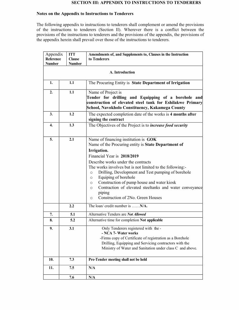
SECTION III: APPENDIX TO INSTRUCTIONS TO TENDERERS Notes on the Appendix to Instructions to Tenderers The following appendix to instructions to tenderers shall complement or amend the provisions of the instructions to tenderers (Section II). Wherever there is a conflict between the provisions of the instructions to tenderers and the provisions of the appendix, the provisions of the appendix herein shall prevail over those of the instructions to tenderers. Appendix
Reference Number ITT
Clause Number Amendments of, and Supplements to, Clauses in the Instruction
to Tenderers A. Introduction
1. 1.1 The Procuring Entity is State Department of Irrigation 2. 1.1 Name of Project is
Tender for drilling and Equipping of a borehole and construction of elevated steel tank for Eshilakwe Primary School, Navokholo Constituency, Kakamega County 3. 1.2 The expected completion date of the works is 4 months after signing the contract
4. 1.3 The Objectives of the Project is to increase food security 5. 2.1 Name of financing institution is GOK Name of the Procuring entity is State Department of
Irrigation. Financial Year is 2018/2019 Describe works under the contracts The works involves but is not limited to the following:- o Drilling, Development and Test pumping of borehole o Equiping of borehole o Construction of pump house and water kiosk o Contraction of elevated steeltanks and water conveyance piping o Construction of 2No. Green Houses
2.2 The loan/ credit number is ……N/A. 7. 5.1 Alternative Tenders are Not Allowed 8. 5.2 Alternative time for completion Not applicable 9. 3.1 Only Tenderers registered with the -
- NCA 7- Water works -Firms copy of Certificate of registration as a Borehole Drilling, Equipping and Servicing contractors with the Ministry of Water and Sanitation under class C and above. 10. 7.3 Pre-Tender meeting shall not be held
11. 7.5 N/A 7.6 N/A
C. Preparation of Tenders
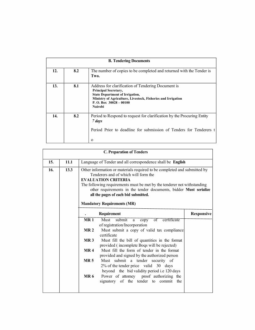
15. 11.1 Language of Tender and all correspondence shall be English 16. 13.3 Other information or materials required to be completed and submitted by Tenderers and of which will form the
EVALUATION CRITERIA The following requirements must be met by the tenderer not withstanding other requirements in the tender documents, bidder Must serialize all the pages of each bid submitted.
Mandatory Requirements (MR) . Requirement Responsive MR 1 Must submit a copy of certificate of registration/Incorporation MR 2 Must submit a copy of valid tax compliance certificate MR 3 Must fill the bill of quantities in the format provided ( incomplete Boqs will be rejected) MR 4 Must fill the form of tender in the format provided and signed by the authorized person MR 5 Must submit a tender security of 2% of the tender price valid 30 days beyond the bid validity period i.e 120 days MR 6 Power of attorney proof authorizing the signatory of the tender to commit the B. Tendering Documents
12. 8.2 The number of copies to be completed and returned with the Tender is Two.
13. 8.1 Address for clarification of Tendering Document is Principal Secretary,
State Department of Irrigation, Ministry of Agriculture, Livestock, Fisheries and Irrigation P. O. Box 30028 – 00100 Nairobi
14. 8.2 Period to Respond to request for clarification by the Procuring Entity 7 days Period Prior to deadline for submission of Tenders for Tenderers to
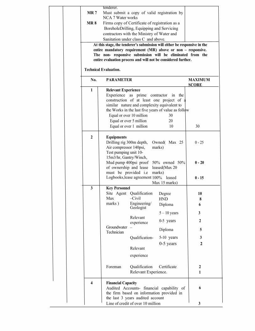
tenderer. MR 7 Must submit a copy of valid registration by NCA 7 Water works MR 8 Firms copy of Certificate of registration as a BoreholeDrilling, Equipping and Servicing contractors with the Ministry of Water and Sanitation under class C and above.
At this stage, the tenderer’s submission will either be responsive in the entire mandatory requirement (MR) above or non – responsive. The non- responsive submission will be eliminated from the entire evaluation process and will not be considered further.
Technical Evaluation. No. PARAMETER MAXIMUM
SCORE 1 Relevant Experience Experience as prime contractor in the construction of at least one project of a similar nature and complexity equivalent to the Works in the last five years of value as follow Equal or over 10 million 30 Equal or over 5 million 20 Equal or over 1 million 10 30 2 Equipments
Drilling rig 300m depth, Air compressor 140psi, Test pumping unit 10-15m3/hr, Gantry/Winch, Owned( Max 25 marks) 0 - 25 Mud pump 400psi proof 50% owned 50% of ownership and lease leased(Max 20 must be provided i.e marks) 0 - 20 Logbooks,lease agreement 100% leased 0 - 15 Max 15 marks) 3 Key Personnel Site Agent Qualification Max –Civil Degree 10 HND 8 marks ) Groundwater Technician Engineering/Geologist Relevant experience – Qualification- Relevant experience Diploma 6 5 – 10 years 3 0-5 years 2 Diploma 5 5-10 years 3 0-5 years 2Foreman Qualification Certificate 2 Relevant Experience. 4 Financial Capacity Audited Accounts- financial capability of 1
6 the firm based on information provided in the last 3 years audited account Line of credit of over 10 million 3
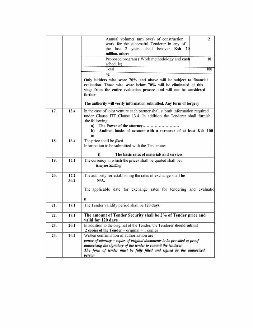
Annual volume( turn over) of construction 2 work for the successful Tenderer in any of the last 2 years shall be:over Ksh 20 million. others Proposed program ( Work methodology and cash 10 schedule) Total 100%
Only bidders who score 70% and above will be subject to financial evaluation. Those who score below 70% will be eliminated at this stage from the entire evaluation process and will not be considered further The authority will verify information submitted. Any form of forgery or misinformation will lead to cancellation of the bid 17. 13.4 In the case of joint venture each partner shall submit information required under Clause ITT Clause 13.4. In addition the Tenderer shall furnish the following ,
a) The Power of the attorney……………………… b) Audited books of account with a turnover of at least Ksh 100m 18. 16.4 The price shall be fixed Information to be submitted with the Tender are:
i) The basic rates of materials and services 19. 17.1 The currency in which the prices shall be quoted shall be:
Kenyan Shilling 20. 17.2
30.2 The authority for establishing the rates of exchange shall be N/A. The applicable date for exchange rates for tendering and evaluation 21. 18.1 The Tender validity period shall be 120 days.
22. 19.1 The amount of Tender Security shall be 2% of Tender price and valid for 120 days
23. 20.1 In addition to the original of the Tender, the Tenderer should submit 2 copies of the Tender – original + 1 copies
24. 20.2 Written confirmation of authorization are power of attorney – copies of original documents to be provided as proof authorizing the signatory of the tender to commit the tenderer. The form of tender must be fully filled and signed by the authorized person

( D. Submission of Tenders 25. 21.2 a) Tenders shall be submitted to
Principal Secretary, State Department of Irrigation Ministry of Agriculture, Livestock, Fisheries and Irrigation P.O Box 30028-00100 NAIROBI Tender number MALFI/SDI/OT/005/2018-2019
27. 22.1 The deadline for Tender submission is a) 31st January, 2019 12.00 Noon. b) Time …12.00 am
28. 22.3 The extension of the deadline for submission of Tenders shall be made not later than N/A. 29 24.4 Expiry of Tender validity is 120 days
E. Opening and Evaluation of Tenders 29. 25.1 The Tender opening shall take place at:
State Department of Irrigation Ministry of Agriculture, Livestock, Fisheries and Irrigation (Maji House) P.O Box 30028-00100 NAIROBI
30. 32.3 Additional Preference Not applicable 31. 34.1 Post- qualification will be undertaken 32. 38.1 Percentage for quantities increase or decrease is 15% 26. 21.2 b) Project name: Construction of Eshilakwe Irrigation Project

F. Award of Contract 33. 41.1 The amount of Performance Security shall be 10% of the contract price 34. 42.1 The Advance Payment shall be …20% of the contract amount 35. 43.1 The proposed adjudicator for the project is:
Chartered Institute of Arbitrators (KenyaBranch) [insert name of the proposed adjudicator] whose hourly rate shall be determined by the Institution
G. Review of Procurement Decisions 37. 46.1 The address for submitting appeals to Administrative Review Board : The Secretary, Public Procurement Administrative Review Board , The Public Procurement Oversight Authority, 10th Floor, National Bank House P.O. Box 58583-00200, NAIROBI, Kenya. Tel: +254 (0) 20 3244000
SECTION IV. CONDITIONS OF CONTRACT, PART I – GENERAL CONDITIONS
CONDITIONS OF CONTRACT, PART I – GENERAL CONDITIONS The Conditions of Contract, Part I – General Conditions, shall be those forming Part I of the “Conditions of Contract for works of Civil Engineering Construction, Fourth Edition 1987, re-printed in 1992 with further amendments, prepared by the Federation Internationale des Ingenieurs – conseils (FIDIC). The Conditions are subject to variations and additions set out in Part II hereof entitled “Conditions of Contract, Part II - Conditions of Particular Application”. Note i. The standard text of the General Conditions of Contract must be retained intact to facilitate its reading and interpretation by tenderers. Any amendments and additions to the General Conditions, specific to a given Contract, should be introduced in the Conditions of Particular Application or in the Appendix to Form of Tender. ii. The Conditions of Particular Application take precedence over the General Conditions of Contract. iii. Copies of the FIDIC Conditions of Contract can be obtained from: FIDIC Secretariat P.O. Box 86 1000 Lausanne 12
Switzerland Fax: 41 21 653 5432 Telephone: 41 21 653 5003
SECTION IV:

SECTION V: CONDITIONS OF CONTRACT PART II – CONDITIONS OF
PARTICULAR APPLICATION GENERAL The Conditions of Contract Part II – Conditions of Particular Application, modify and compliment like-numbered clauses in the Conditions of Contract Part I – General Conditions. Both Parts shall be read together, with the Conditions of Particular Application prevailing in case of conflict or discrepancy. Clauses of the General Conditions not specifically modified and supplemented shall remain in effect. Clause No. Definitions and Interpretation 1.1 (a) (i) The said “Employer” shall be,STATE DEPARTMENT OF IRRIGATION,
MINISTRY OF AGRICULTURE, LIVESTOCK, FISHERIES AND IRRIGATION Represented by PRINCIPAL SECRETARY (iv) The said “Engineer” shall be IRRIGATION SECTRETARY, or any other competent person appointed by the Employer, and notified to the Contractor, to act in replacement of the Engineer. (b)(i) Insert in line 2 after “the Bills of Quantities”, the following, ”the rates entered by the Contractor (whether or not such rate be employed in computation of the Contract Price)”. Add the following sub-clause;
Engineer’s Duties and Authority 2.1 (b) The Engineer shall obtain specific approval of the Employer before taking any of the following actions specified in Part I: (i) Consenting to the sub-letting of any part of the Works under clause 4. (ii) Certifying additional cost determined under Clause 12 (iii) Determining an extension of time under Clause 44 (iv) Issuing a variation under Clause 51 except in an emergency situation as reasonably determined by the Engineer. (v) Fixing rates or prices under clause 52
Assignment and Subcontracting 4.1 Delete the second and third sentence and substitute: No single subcontract may be for more than 10 percent of the Contract Price nor shall the sum of all subcontracts exceed 25 percent of the Contract price. No one subcontractor may be awarded subcontracts to a total value greater than 10 percent of the Contract Price. All subcontracts greater than 2 percent of the Contract Price are to have the prior consent of the Engineer. The Contractor shall however, not required such consent for purchases of materials or to place contracts for minor details or for any part of the Works of which the manufacturer of supplier is named in the Contract. Any such consent shall not relieve the Contractor from any liability or obligation under the Contract and he shall be responsible for the acts, defaults and neglects of any subcontractor, his agents, servants or workmen as fully as if they were the acts, defaults or neglects of the Contractor, his agents, servants or workmen. Contract Documents 5.1 (a) The language governing this Contract shall be English. The “Ruling Language” which shall be used to interpret this Contract shall be English. Communication between the Contractor and Engineer or Engineer’s representative shall be in English. (b) The law applicable to this Contract shall be the laws of the Republic of Kenya. Except to the extent otherwise provided by the Contract, the Kenyan courts shall have exclusive jurisdiction to hear and to determine all actions and proceedings in connection with and arising out of the Contract, and the Contractor shall submit to the jurisdiction of Kenyan courts for the purpose of any such actions and proceedings. 5.2 Delete the documents listed 1-6 and substitute: (1) The Contract Agreement; (2) The Notification of Award; (3) Tender and Appendix to Form of Tender; (4) The Conditions of Contract Part II; (5) The Conditions of Contract Part I (FIDIC); (6) The Special Specifications; (7) Clarifications and rectifications accepted by the Employer; and (8) The Drawings; (9) The priced Bills of Quantities; and (10) Schedules and other documents forming part of the Contract. 8.1 Add to sub clause 8.1 the following:

(a) Within 21 calendar days after receipt of the Engineer’s order to commence the Works, the Contractor shall establish an office at the Site duly equipped for the Contractor’s representative and his supervisory personnel. The Contractor shall maintain this office throughout the Contract period. The said office shall be the legal domicile of the Contractor, and all correspondence sent to this office shall be deemed to have been sent to the Contractor’s head office. (b) A foreign Contractor or a Kenya-foreign joint venture, if not registered in Kenya under the applicable laws of Kenya, shall undertake registration upon receipt of the letter of acceptance and prior to signing of the Contract. 10.1 Performance Security In lines 1, 2 and 3 delete the words “If the Contract… within 28 days” and substitute “The Contractor shall obtain a Performance Security within 14 calendar days ………” Add the following at the end of this Sub-Clause:- The Performance Security shall be issued by a Bank incorporated in Kenya. The amount of guarantee shall be as stated in the Appendix to Form of Tender. The bank guarantee shall be issued either (a) by an established and reputable bank approved by the Employer and located in Kenya .The performance security shall be in Kenya Shillings. The performance security may, subject to the approval of the Engineer, be adjusted at the end of each period of 12 months to reflect the residual value of the Contract Works. 10.2 The performance guarantee shall be valid until a date 28 days after the date of issue of the Taking-Over Certificate. The security shall be returned to the Contractor within 28 days of the expiration. 10.3 Delete sub-clause 10.3
11.1 Inspection of Site Add the words “and the Contractor shall be deemed to have based his tender on all the aforementioned” after the words “affect his tender”. Delete the last paragraph completely and replace with the following: “The Employer in no way guarantees completeness nor accuracy of the

soil, materials, subsurface and hydrological information made available to the Contractor at the time of tendering or at any other time during the period of the Contract, and the Contractor shall be responsible for ascertaining for himself all information as aforesaid for the execution of Works and his tender shall be deemed to have been priced accordingly. 14.1 Programme to be Submitted The time within which the Programme shall be submitted shall be twenty one (21) days. This detailed Programme shall be based upon the programme submitted by the Contractor as part of his tender and shall, in no material manner, deviate from the said programme. The programme of works shall be prepared in a manner to achieve a minimum of 3500m3 in 6 days. The Contractor shall allow in his Programme for the following 11 public holidays per calendar year in Kenya upon which the Contractor shall not be permitted to work New Year’s Day (1st January) Good Friday April Easter Monday April Labour Day (1st May) Madaraka Day (1st June) Mashujaa Day (20th October) Jamhuri Day (12th December) Christmas Day (25th December) Boxing Day (26th December)
14.2 Add the following at the end of this sub clause:- The Employer shall have the right to withhold payment at any time if the Contractor fails to submit the contractual construction programmes in accordance with sub clause 14.1 above or revise construction programmes due to his negligence, failure or omission. 14.3 Cash Flow Estimate to be Submitted The time limit within which a detailed cash flow estimate is to be submitted shall be twenty eight (21) days. In preparing the estimates, the Contractor shall make provision for Advance payment, repayment of advance, retention, payment for services provided by the Employer and timing implications of sub clause 60 – Certificates and Payments. 15 Contractor’s Superintendence Add the following at the end of the first paragraph of sub-clause 15.1:
15.1 The Contractor shall, within seven (7) days of receipt of the
Engineer’s order to commence the Works, inform the Engineer in writing, the name of the Contractor’s representative and the anticipated date of his arrival on Site. Add the following sub-clause 15.2: 15.2 The Contractor’s agent or representative on the Site shall be an Engineer registered by the Engineer’s Registration Board of Kenya in accordance with the Laws of Kenya cap. 530 or have equivalent status approved by the Engineer and shall be able to read, write and speak English fluently. 16.2 Engineer at Liberty to object At the end of this clause add “by a competent substitute approved by the Engineer at the Contractor’s own expense”. The Contractor is encouraged to the extent practicable and reasonable, to employ staff and labour with appropriate qualifications who are Kenyan citizens.
19 Safety, Security and Protection of the Environment 19.1 Add at the end of sub clause 19.1 the following: - The formulation and enforcement of an adequate safety program shall be the obligation of the Contractor with respect to all the Works under this Contract, regardless of whether performed by the Contractor or his subcontractors. The Contractor shall, within 14 days after commencement of the Works, meet the Engineer to present and discuss his plan for the establishment of such safety measures as may be necessary to provide against accidents, unsafe acts and so forth. Within 28 days after commencement of the Works, the Contractor shall submit a written safety program to the Engineer covering the overall Works and based on the laws and regulations of Kenya. In addition, he shall prepare special safety programs for blasting and handling of explosives as stipulated in the General and Special Specifications. Notwithstanding the foregoing, the Contractor shall observe the following measures with a view to reducing or eliminating adverse environmental effects by the Site Works: (i) All queries and borrow pits shall be filled and landscaped to their original state after extraction of construction material (ii) Soil erosion due to surface runoff or water from culverts or other drainage structures should be avoided by putting in place proper erosion control measures that shall include, but not limited to grassing , planting of trees, gabions etc.

(iii) Long traffic diversion roads shall be avoided so as to minimize the effect of dust on the surrounding environment. In any case all diversions shall be kept damp and dust free at the Contractor’s expense. (iv) Spillage of oils, fuels and lubricants shall be avoided and if spilt, shall be collected and disposed off in such a way as not to adversely affect the environment. (v) Rock blasting near settlement areas shall be properly coordinated with the relevant officers of the Government so as to minimize noise pollution and community interference. (vi) Dumping shall be done only at designated dumping areas and not haphazardly on surroundings. 21 Insurance of Works & Contractor’s Equipment 21.1 (a) Delete the first sentence of this clause and replace with the following: “Prior to commencement of the Works the Contractor shall, without limiting his or the Employer’s obligations and responsibilities under Clause 20, insure to the satisfaction of the Employer.” (b) Add the following words at the end of sub - paragraph (a) and Immediately before the last word in (b) “it being understood the insurance shall provide for compensation to be payable in the types and proportions of the currencies required to rectify the loss or damage incurred.” In sub clause 21.1(b), delete the words “or as may be specified in Part II of these Conditions”. 21.2 (a) Delete the words “from the start of Work at the Site” and substitute with the words “from the first working day after the commencement date” (c) Add the following sub-clause: “It shall be the responsibility of the Contractor to notify the insurance company of any change in the nature and extent of the Works and to ensure the adequacy of the insurance coverage at all times during the period of the Contract”. 23.1 Third Party Insurance Add the following at the beginning of this sub-clause:- “Prior to commencement of the Works ……………………….” 23.2 Minimum Amount of Insurance Add the following at the end of this sub-clause:-“……………… with no limits to the number of occurrences.”

25.1 Insert the words “as soon as practicable after the respective insurances have been taken out but in any case” before the words “Prior to the start of Work at the Site” Add the following sub-clauses 25.5 to 25.7 25.5 Insurance Notices Each policy of insurance effected by the Contractor for the purpose of the Contract shall include a provision to the effect that the Insurer shall have a duty to give notice in writing to the Contractor and Employer of the date when a premium becomes payable not more than thirty (30) days after the giving of such notice. 25.6 Re-insurance in Kenya The risks against which the Contractor is obliged to insure under the Contract shall be insured through established and reputable companies approved by the Employer and located in Kenya and any cover against risks which the Contractor may enjoy shall be reinsured in Kenya by an approved Kenyan Insurance Company In respect of the Contractor’s obligations under the Contract. 25.7 It shall be the responsibility of the Contractor to notify the insurers under any of the insurances referred or event which by the terms of such insurances are required to be so notified and the Contractor shall indemnify and keep indemnified the Employer against all losses, claims, demands, proceedings, costs, charges and expenses whatsoever arising out of or in consequence of any default by the Contractor in complying with the requirements of this sub clause whether as a result of avoidance of such insurance or otherwise. 26. Compliance with Statutes, Regulations Add the following sub-clause 26.2;- The Employer will repay or allow to the Contractor all such sums as the Engineer shall certify to have been properly payable and paid by the Contractor in respect of such fees. Provided always that, without prejudice to sub clause, nothing contained in this clause shall be deemed to render the Employer liable to all claims which may be considered to fall within the provisions of clause 22.1.
Royalties 28.2 Add the following at the end of this sub-clause; “The Contractor shall also be liable for all payments or compensation, if any, that are

levied in connection with the dumping of part or all of any such material.” Interference with Traffic and Adjoining Properties 29.2 Add new sub-clause 29.2; The Contractor shall reinstate all properties whether public or private which are damaged in consequence of the construction and maintenance of the Works to a condition at least equal to that prevailing before his first entry on them. If in the opinion of the Engineer the Contractor shall have failed to take reasonable and prompt action to discharge his obligations in the matter of reinstatement, the Engineer will inform the Contractor in writing of his opinion, in which circumstances the Employer reserves the right to employ others to do the necessary work of reinstatement and to deduct the cost thereof from any money due or to become due to the Contractor. The Contractor shall promptly refer to the Employer all claims, which may be considered to fall within the provisions of Clause 22.1.
Labour 34.2 Conditions of Employment of Labour The Contractor shall be responsible for making all arrangements for and shall bear all costs relating to recruitment, obtaining of all necessary visas, permits or other official permission for movements of staff and labour. 34.3 Fair Wages The Contractor shall, in respect of all persons employed anywhere by him in the execution of the Contract, observe and fulfil the following conditions: (a) The Contractor shall pay the rates of wages, observe hours of labour and provide conditions, housing amenities and facilities not less favourable than those required by the Regulation of wages (Building and Construction Industry) Order 1998, and any subsequent amendments thereto, or in any ministry of labour or other government department in consultation with the district whose general circumstances in the trade or industry in which the Contractor is engaged are similar. The Contractor shall at all times during the continuation of the Contract display, for the information of his employees, a notice setting out the general rates of wages, hours and conditions of labour of his employees and a copy of this clause. (b) In the absence of any rates for wages, hours or conditions of labour so established, the Contractor shall pay rates or wages and observe hours and conditions for labour which are not less favourable than the general circumstances in the trade or industry in which the Contractor is engaged.
(c) Where the absence of established rates of wages, hours and conditions of labour or the dissimilarity of the general circumstances in the trade or industry in which the Contractor is engaged prevent the Contractor from observing rates of wages, hours and conditions of labour ascertained under sub-paragraph (a) or (b) above, the Contractor in fixing the rates of wages, hours and conditions of labour of his employees shall be guided by the advice of the labour department. (d) The Contractor shall recognize the freedom of his employees to be members of trade unions. (e) The Contractor shall maintain records of the times worked by, and the wages paid to his employees. The Contractor shall furnish to the Employer, if called upon so to do, particulars of the rates of wages, hours and conditions of labour as the employer may direct. (f) The Contractor shall be responsible for observance by his sub-Contractors of the foregoing provisions. 34.4 Breach of Fair Wages Clause Should a claim be made to the Employer alleging the Contractor’s default in payment of fair wages to any workman employed on the Contract and if proof thereof satisfactory to the Employer is furnished by the labour department, the Employer may, failing payment by the Contractor, pay the claims out of any monies due or which may become due to the Contractor under the Contract. 34.5 Recruitment of Unskilled Labour Any additional unskilled labour which may be required by the Contractor for the Works and which is not in his employ at the time of the acceptance of the tender shall be recruited by the Contractor from the labour office nearest to the Site of the Works. 34.6 Compensation for injury The Contractor shall, in accordance with the Workman’s Compensation Act Chapter 236 of the laws of Kenya and any other regulations in force from time to time in Kenya, pay compensation for loss or damage suffered in consequence of any accident or injury or disease resulting from his work to any workman or other person in the employment of the Contractor or any sub-contractor. 34.7 Labour Standards a) The Contractor shall comply with the existing local labour laws, regulations and labour standards. b) The Contractor shall formulate and enforce an adequate safety program with respect to all Work under this Contract, whether Performed by the Contractor or his sub-contractors. The Contractor has

assurance from the Employer of cooperation where the implementation of these safety measures requires joint cooperation. c) Upon written request of the Employer the Contractor will remove or replace any of his employees employed under this Contract. 34.8 Recruitment The Contractor shall not induce personnel of the employer or the Engineer to leave their regular employment and shall not, without the prior consent in writing of the Employer, employ personnel who have resigned from such service within the preceding twelve months. 35 Add the following sub clauses 35.2 and 35.3:- 35.2 The Contractor shall maintain such records and make such reports concerning safety, health and welfare of persons and damage to property as the Engineer may from time to time prescribe. 35.3 The Contractor shall report to the Engineer details of any accident as soon as possible after its occurrence. In the case of any fatality or serious accident, the Contractor shall, in addition, notify the Engineer immediately by the quickest available means. The Contractor shall also notify the relevant authority(s) whenever such report is required by the law. 41.1 Commencement and Delays Insert immediately after the word Works------ “on Site within 14 days” and before the word ----------after 41.2 Definition of Commencement For the purposes of this clause, the Works shall be deemed to have commenced when all of the following conditions are satisfied; a) The approved competent and authorized agent or representative of the Contractor is resident in the project area and is giving his whole time to the superintendence of the Works. b) The provision by the Contractor of evidence that all insurances required by the Contract are in force. c) The Contractor has an established office in the project area with postal address for receipt of correspondence. d) The principal items of constructional plant have been brought to Site and put to work in the execution of the permanent Works.
42.4 Possession of Site and Access Thereto Add the following to this clause 42.4; The Contractor shall not enter any part of the Site until he has requested and received permission to do so from the Employer or the Engineer. The site may change during implementation which will be upon instruction from the Employer or the Engineer. The Contractor shall not use any portion of the Site for any purpose not connected with the Works. 44.1 Add at the end of sub-clause 44.1 the following: Neither rains falling between 1st November and 31st December (inclusive) and between 1st February and 31st May (inclusive) nor floods caused by such rains shall be deemed exceptional weather conditions such as may fairly entitle the Contractor to an extension of time for the completion of the Work. 45 Working Hours Delete sub-clause 45.1 and substitute: “Subject to any provision to the contrary contained in the Contract, the Contractor shall have the option to work continuously by day and by night and on locally recognized days of rest. If the Contractor requests for permission to work by day and night and if the Engineer shall grant such permission, the Contractor shall not be entitled to any additional payment for so doing. All such work at night shall be carried out without unreasonable noise or other disturbance and the Contractor shall indemnify the Employer from and against any liability for damages on account of noise or other disturbance created while or in carrying out night work and from and against all claims, demands, proceedings, costs, charges and expenses whatsoever in regard or in relation to such liability. In addition, the Contractor shall be required to provide, for any work carried out by night or recognized days of rest, adequate lighting and other facilities so that the Work is carried out safely and properly. In the event of the Engineer granting permission to the Contractor to work double or rotary shifts or on Sundays, the Contractor shall be required to meet any additional costs to the Employer in the administration and supervision of the Contract arising from the granting of this permission. 47.2 Reduction of Liquidated Damages There shall be no reduction in the amount of liquidated damages in the event that a part or a section of the Works within the Contract is certified as completed before the whole of the Works comprising that Contract. No bonus for early completion of the Works shall be paid to the Contractor by the Employer.

The sum stated in the Appendix to Form of Tender as liquidated damages shall be increased by a sum equivalent to any amount payable by the Employer to the Contractor under clause 70.1 in respect of an increase in costs in such period that would not have been incurred by the Contractor if the Works had been completed by the due date for completion prescribed by clause 43. Defects Liability 49.2 Add at the end of this sub-clause the following sentence:- Any work ordered to be executed under this clause shall be done at a time and in a manner as directed by the Engineer so as to interfere as little as possible with the operations of the Employer or of other contractors and no extension(s) of the defects liability period will be allowed for the execution of this Work. Add the following sub-clause 49.5 to this Clause:- 52 Variations 52.1 Add the following final sentence to this sub clause:- The agreement, fixing or determination of any rates or prices as aforesaid shall include any foreign currency and the proportion thereof. 52.4 Day work Add the following at the end of this sub-clause: The Work so ordered shall immediately become part of the Works under the Contract. The Contractor shall, as soon as practicable after receiving the Daywork Order from the Engineer undertake the necessary steps for due execution of such Work. Prior to commencement of any work to be done on a Daywork basis, the Contractor shall give a notice to the Engineer stating the exact time of such commencement. 54 Plant, Temporary Works and Materials Delete Sub-Clauses 54.3 to 54.4 entirely. For the purpose of these Clauses, the term “Equipment” shall be read as “Contractor’s Equipment” where the context so requires. 54.1 Line 5: - Add “written” between “the” and “consent”.
Quantities 55.1 Delete sub-clause 55.1 and substitute with the following;
The quality and quantity of the Work included in the Contract Price shall be deemed to be that which is set out in the Contract Bills. The Bills, unless otherwise expressly stated therein, shall be deemed to have been prepared In accordance with the principles of the latest edition of the Civil Engineering Standard Method of Measurement. Any error in description or in quantity or any omission of items from the Contract Bills or Specifications shall not vitiate this Contract but shall be corrected and deemed to be a variation required by the Engineer. Subject to the foregoing, any error whether arithmetical or not in the computation of the Contract Price shall be deemed to have been accepted by the parties hereto. The Contract Price shall not be adjusted or altered in any way whatsoever otherwise than in accordance with the express provisions of these Conditions. 55.2 Add as a new sub-clause: “Items of Work described in the Bills of Quantities for which no rate or price has been entered in the Contract shall be considered as included in other rates and prices in the Contract and will not be paid for separately by the Employer. Measurement 56.1 Delete sub clause 56.1 and replace with the following:- The Contractor shall prepare and submit to the Engineer all necessary field notes and other records taken and computations made for the purpose of quantity measurements, of which the forms shall be approved by the Engineer, for the monthly progress payment under clause 60. The measurement of work quantities made by the Contractor shall be verified and certified by the Engineer based on the above-mentioned documents. The Contractor shall furnish all personnel, equipment and materials to make such surveys and computations as necessary to determine the quantities of work performed. Unless otherwise prescribed in the specifications or the drawings, all measurements for payment shall be made by the dimensions, lines and grades as shown on the drawings or by direct survey of which the methods shall be approved by the Engineer. The documents submitted for measurement and payment shall become the property of the Employer and shall be used to the extent necessary to Determine the monthly progress payment to be made to the Contractor under the Contract. Direct survey, if done, shall be subject to checking and verification by the Engineer and all errors in the said survey work and related computations as found during such checking shall be immediately corrected by the Contractor. 57.1 Delete sub clause 57.1 and substitute with the following:- The Works shall be measured net with deductions made in accordance with The principles of the latest edition of the Civil Engineering Standard Method of Measurement. All measurements shall be given in metric (SI) units.

Provisional Sums 58.4 Prime Cost sum Wherever an item in the Bills of Quantities has been referred to as a “P.C. Sum” (Prime Cost Sum), that item shall be construed as a Provisional sum and the provisions of Sub-clauses 58.1 to 58.3 will apply. 59.5 Add the following paragraph at the end of sub clause 59.5:- If the Engineer desires to secure final payment to any nominated sub-contractor before final payment is due to the Contractor and if such sub-contractor has satisfactorily indemnified the Contractor against any latent defects, the Engineer may, in an interim certificate, include an amount to cover the said final payment, and thereupon the Contractor shall pay to such nominated sub-contractor the amount so certified. Upon such final payment, the amount named in the Appendix to Form of Tender as Limit of Retention Money shall be reduced by the sum which bears the same ratio to the amount as does the subcontract and sub-contractor shall be discharged from all liability for the Work, materials or goods executed or supplied by such subcontractor under the Contract to which the payment relates. Certificates and Payment Delete Sub-clauses 60.1 to 60.10 entirely and substitute with the following:- 60.1 Advance Payment In the event that an advance payment is granted, the following shall apply:- a) On signature of the Contract, the Contractor shall at his request, and without furnishing proof of expenditure, be entitled to an advance of 20% (twenty percent) of the original amount of the Contract. The advance shall not be subject to retention money. b) No advance payment may be made before the Contractor has submitted proof of the establishment of deposit or of a directly liable guarantee satisfactory to the Employer in the amount of the advance payment. The guarantee shall be in the same currency as the advance. c) Reimbursement of the advance shall be effected by deductions from monthly interim payments. d) Reimbursement of the lump sum advance shall be made by deductions from the Interim payments and where applicable from the balance owing to the Contractor. Reimbursement shall begin when the amount of the sums due
under the Contract reaches 20% of the original amount of the Contract. It shall have been completed by the time 80% of this amount is reached. The amount to be repaid by way of successive deductions shall be calculated by means of the formula: R =A ( x1 – x11) 80 – 20 Where: R = the amount to be reimbursed A = the amount of the advance which has been granted X1 = the amount of proposed cumulative payments as a percentage of the original amount of the Contract. This figure will exceed 20% but not exceed 80%. X11 = The amount of the previous cumulative payments as a percentage of the original amount of the Contract. This figure will be below 80% but not less than 20%. (e) with each reimbursement the counterpart of the directly liable guarantee may be reduced accordingly. 60.2 Interim Payment Certificate The Contractor shall submit to the Engineer, in the manner required by the Engineer after the end of each month a statement showing the estimated total value of permanent Work properly executed and materials or goods for permanent works brought to Site up to the end of the previous month (if the value shall justify the issue of an interim certificate) together with any adjustments under clause 70 and any outstanding claims and sums the Contractor considers may be due to him. The Contractor shall amend or Correct his estimate as directed by the Engineer and the latter shall not accept it until he is satisfied that it is fair and reasonable. With respect to the said materials and goods, no payment for them shall be made unless;- (i) The materials are in accordance with the specifications for the Works; (ii) The materials have been delivered to Site and are properly stored and protected against loss, damage or deterioration; (iii) The Contractor’s record of the requirements, orders, receipts and use of materials are kept in a form approved by the Engineer, and such records are available for inspection by the Engineer; (iv) The Contractor has submitted a statement of his cost of acquiring and delivering the materials and goods to the Site, together with such documents as may be required for the purpose of evidencing such cost; (v) The materials are to be used within a reasonable time.
The Contractor will be paid on the certificate of the Engineer the amount due to him on account of the estimated total value of the permanent Work executed up to the end of the previous month together with such amount (not exceeding 75% of the value) as the Engineer may consider proper on account of materials and goods for permanent Work delivered by the Contractor on Site and in addition, such amount as the Engineer may consider fair and reasonable for any Temporary Works for which separate amounts are provided in the Bill of Quantities, all of which shall be subject to a retention of the percentage named in the Appendix to Form of Tender until the amount retained (hereinafter and in all Contract documents called the “Retention Money”) shall reach the “Limit of Retention Money” named in the said Appendix. Provided always that no interim certificate shall be issued for a sum [such sum always being the net amount thereof after all deductions for retention etc) less than that named in the Appendix to Form of Tender as “Minimum Amount of Interim Certificate” at one time. Within 14 days after receiving a statement from the Contractor as aforesaid, and subject to the Contractor having made such further amendments and corrections as the Engineer may require, the Engineer shall issue a Certificate of Payment to the Employer showing the amount due, with a copy to the Contractor. The Engineer shall not unreasonably withhold certifying an Interim Payment Certificate and where there is a dispute regarding an item for payment, the Engineer may delete this disputed item from the Interim Payment Certificate and certify the remainder for payment provided the said payment is in accordance with the preceding paragraph. In cases of difference in opinion as to the value of any item, the Engineer’s view shall prevail. 60.3 Final Account and Final Payment Certificate As soon as possible after the issue of Taking - Over Certificate or the termination of the Contract and not later than the time of issue of Defects Liability Certificate, the Contractor shall prepare and submit to the Engineer (with a copy to the Employer), a Statement of Final Account showing in detail the total value of work done in accordance with the Contract together with all sums paid in previous payments. Within thirty(30) after receipt of such further information as may be reasonably required from the Contractor for its verification, the Engineer shall check the said statement, prepare and submit a Final Payment Certificate to the Employer (with a copy to the Contractor). The Final Payment Certificate shall state; (a) The (final) total value of all Work done in accordance with the Contract; (b) After giving credit to the Employer for all amounts previously paid to the Contractor, the balance, if any, due from the Employer to the Contractor or the Contractor to the Employer, as the case may be.
Unless the Contractor notifies the Engineer of his objection to the Final Payment Certificate within twenty eight [28] days of delivery thereof, he shall be deemed to have agreed that he accepts the total Contract Price as set out in the Final Payment Certificate as full settlement for all work done under the Contract including any claims, variations and omissions thereof. However, a Final Certificate of Payment shall not be conclusive: a) to the extent that fraud or dishonesty relates to or affects any matter dealt with in the Certificate, or b) if any arbitration or court proceedings under the Contract have been commenced by either party before the expiry of 84 days after the issue of the Final Certificate of Payment. 60.4 Payment of Certificates Payment upon each of the Engineer’s Certificates for Interim Payments shall be made by the Employer within the time stated in the Appendix to Form of Tender from the date of issue of each Certificate of Payment. Payment upon the Engineer’s Final Payment Certificate shall be made by the Employer within the time stated in the Appendix to Form of Tender from the date of issue of the Final Certificate of Payment signed by the Engineer and countersigned by the Contractor or his authorised agent or representative. Making of a payment by the Employer shall be considered to have been duly executed on the day that the Employer has issued a cheque. 60.5 Payment of Retention Money One half of the retention money shall become due upon the issue of a Taking – Over Certificate and shall be paid to the Contractor when the Engineer shall certify in writing that the last section of the whole of the Works has been substantially completed and the other half shall be paid to the Contractor after the expiration of the Defects Liability Period and the issue of a Certificate under Clause 62. Provided always that if such time there shall remain to be executed by the Contractor any Works ordered during such period pursuant to Clauses 49 and 50 thereof, the Employer shall be entitled to withhold payment [until the completion of such Works] of so much of the second half of the Retention Money as shall in the opinion of the Engineer represent the Costs of the Works so remaining to be executed. Provided further that in the event of different Defects Liability Periods having become applicable to different parts of the Works pursuant to clause 48 hereof the expression “expiration of the Defect Liability Period” shall for the purpose of this Sub-clause be deemed to mean the expiration of the latest of such periods. 60.6 Currency of Payment
The Contract price shall be stated in Kenya Shillings. All payments to the Contractor shall be made in Kenya shillings and foreign currency(s) in the proportion indicated in the tender, or agreed prior to the execution of the Contract Agreement and indicated therein. The rate[s] of exchange for the calculation of the amount of foreign currency payment[s] shall be the rate of exchange indicated in the Tender. If the Contractor indicated foreign currencies for payment other than the currencies of the countries of origin of related goods and services, the Employer reserves the right to pay the equivalent at the time of payment in the currencies of the countries of such goods and services. The Employer and the Engineer shall be notified promptly by the Contractor of any changes in the expected foreign currency requirements of the Contractor during the execution of the Works as indicated in the Statement of Foreign Currency Requirements and the foreign and local currency portions of the balance of the Contract Price shall then be amended by agreement between Employer and the Contractor in order to reflect appropriately such changes. 60.7 Overdue Payments Unless otherwise stated in the appendix interest shall be paid on the overdue amounts and the interest to be paid shall be in accordance with prevailing commercial bank rates. 60.8 Correcting and With-holding The Engineer may by any interim certificate or through the final account make any correction or modification to any previous certified sum and shall have authority, if any work or part thereof is not being carried out to his satisfaction, to omit or reduce the value of such work in any Interim Payment Certificate. 60.9 Completion by Sections. If a Taking-Over Certificate shall be issued for any section or part of the Works separately, the payments herein provided for on or after issue of such a Certificate shall be made in respect of such section or part and references to the Contract Price shall mean such part of the Contract Price as shall in the absence of agreement be apportioned thereto by the Engineer. 60.10 Proportion of Foreign Currency Subject to the provision of sub clause 60.5 the proportion of foreign currency in any amount due to the Contractor or Employer shall be determined in the following manner:- a) For all measured Work, the percentages of foreign currency for the appropriate section of the Bill of Quantities as stated in the schedule of foreign currency requirements shall be applied. b) Variations in the cost of imported materials shall be paid in foreign currency. c) Variations in the cost of locally purchased materials and those due to changes of legislation shall be paid in local currency.
d) For Day works labour and plant, the respective percentages of foreign currency stated in the schedule shall be applied. e) For Day works materials and materials on site, payment in foreign currency will only be made for imported materials. f) The provisions for the deduction and release of Retention Money and the payment of interest shall be applied similarly to both the local and foreign portions. g) The advance mobilization loan, its repayment thereof and liquidated damages shall all be apportioned on the basis of the ration between local and foreign currency indicated in the Contract Price. h) In the event that the payment is for an item not covered in the foregoing paragraphs, the Engineer shall determine the proportion of foreign and local currency based on the information given in the Schedule of Foreign Currency Requirements, together with any additional information he may request the Contractor to provide. 60.11 Statement at Completion Not later than 14 days after the issue of the Taking-Over Certificate in respect of the whole of the works, the Contractor shall submit to the Engineer a statement at completion showing in detail, in a form approved by the Engineer; (a) The final value of all work done in accordance with the Contract up to the date stated in such Taking-Over Certificate. (b) Any further sums which the Contractor considers to be due; and (c) An estimate of amounts, which the Contractor considers, will become due to him under the Contract. Estimate amounts shall be shown separately in the Statement at Completion. The Contractor shall amend and correct the Statement as directed by the Engineer who shall issue a Certificate at Completion to be processed in accordance with sub-clause 60.4. 60.12 Final Statement Not later than 56 days after the issue of the Defects Liability Certificate, the Contractor shall submit to the Engineer for consideration a draft final statement with supporting documents showing in detail, in the form approved by the Engineer; (a) The final value of all work done in accordance with the Contract;
(b) Any further sums which the Contractor considers to be due to him. If the Engineer disagrees with or cannot verify any part of the draft final statement, the Contractor shall submit such further information as the Engineer may reasonable require and shall make such changes in the draft as may be required. 60.13 Discharge Upon submission of the Final Statement, the Contractor shall give to the Employer, with a copy to the Engineer, a written discharge confirming that the total of the Final Statement represents full and final settlement of all monies due to the Contractor arising out of or in respect of the Contract. Provided that such discharge shall become effective only after payment under the Final Payment Certificate issued pursuant to Sub-clause 60.14 has been made and the Performance Security referred to in Sub-clause 10.1 has been returned to the Contractor. 60.14 Final Payment Certificate Upon acceptance of the Final Statement as given in Sub-clause 60.12, the Engineer shall prepare a Final Payment Certificate which shall be delivered to the Contractor’s authorized agent or representative for his signature. The Final Payment Certificate shall state: (a) The final value of all work done in accordance with the Contract; (b) After giving credit to the Employer for all amounts previously paid by the Employer, the balance, if any, due from the Employer to the Contractor or the Contractor to the Employer as the case may be Final Certificate shall be issued for any sum due to the Contractor even if such is less than the sum said named in the Appendix to the Form of Tender. 60.15 Cessation of Employer’s Liability Unless the Contractor notifies the Engineer of his objection to the Final Certificate within fourteen days of delivery thereof he shall be deemed to have agreed that he accepts the total Contract Price as set out in the Final Certificate as full settlement for all work done under the Contract including any variations and omissions thereof. 62.1 Defects Liability Certificate Delete the last sentence of this Sub-Clause beginning “Provided that the issue……………………..in Sub-Clause 60.3”. Remedies
63.4 Assignment of Benefit of Agreement Add the following at the end of this sub-clause:- “But on the terms that a supplier or sub-contractor shall be entitled to make any reasonable objection to any further assignment thereof by the Employer and the Employer may pay the supplier or sub-contractor for any such materials supplied or Works executed under such agreement, whether the same be assigned as aforesaid or not, before or after the said determination, the amount due by such arrangement in so far as it has not already been paid by the Contractor”. 65 Special Risks Add sub clause 65.9 as follows: (a) In the event of the Employer unilaterally ordering the final Cessation of performance of the Contract for reasons not specified elsewhere in the Conditions of Contract the Contract shall be considered to be frustrated and the Contractor shall be indemnified as provided for under clause 65.1. (b) In the event of the Employer ordering the adjournment of the Contract before or after commencement of the Works for reasons not specified elsewhere in the Conditions of Contract, the Contractor shall be entitled to indemnity for any injury which he may have suffered as a consequence of such adjournment. The Engineer shall award the Contractor payment of such sum as in his opinion shall be reasonable giving regard to all material and relevant factors including the Contractor’s on costs and overheads, and the nature of the instruction to adjourn the Contract. Settlement of Disputes 67.3 Arbitration For the purposes of this Clause, the Arbitrator shall be a person to be agreed between the parties or failing agreement, the Arbitrator shall be appointed by the appointer designated in the Appendix to the Form of Tender. Add the following paragraph after the last paragraph of sub-clause 67.3: Arbitration shall take place in Nairobi, Kenya. The language of all arbitration proceedings shall be in English. The cost of arbitration shall be apportioned by the Arbitrator according to his findings.
Notices 68.1 Add the following at the end of this sub clause:- Notwithstanding the foregoing, the Contractor shall either maintain an address close to the Works or appoint an agent residing close to the Works for the purpose of receiving notices to be given to the Contractor under the terms of the Contract. This obligation shall be terminated upon the issue of the Certificate of Completion. 68.2 Delete the words “nominated for that purpose in Part II of these Conditions” in this sub-clause. 69.1 Default of Employer In paragraph (a) of this Sub-Clause, delete the words “within 28 days of expiry of the time stated in Sub-clause 60.10” and insert “within 56 days after the expiry of the time stated in Sub-Clause 60.4”. 69.4 Contractor’s Entitlement to Suspend Work Delete the first four lines of this Sub-Clause and replace with the following:- “Without prejudice to the Contractor’s entitlement to interest under Sub-clause 60.7 and to terminate his employment under Sub-Clause 69.1, the Contractor may, if the Employer fails to pay the Contractor the amount due under any certificate of the Engineer within 56 days after the expiry of the time stated in Sub-Clause 60.4…..” Delete sub-clause 69.4 (b) and substitute with the following----“the amount of such cost, which shall be added to the Contract Price. However, the costs due to idle time for plant, equipment and labour shall not be included in the said costs and shall be borne by the Contractor. 69.5 Resumption of Work In line 3 of this Sub-Clause delete the Words “Sub-Clause 60.10” and replace with “Sub-Clause 60.7” Changes in Cost and Legislation (NOT APPLICABLE) 70.1 Delete the sub-clause 70.1 in its entirety and substitute with the following:-
“The Contract Price shall be deemed to have been calculated in the matter set below and shall be subject to the adjustment in the event specified hereunder: (a) The rates contained in the priced Bill of Quantities are based upon the rates of wages and other emoluments and expenses applicable at the site and the date of tender pricing (as defined in sub-clause 70.4 hereinafter); (b) If the said rates of wages and other emoluments and expenses shall be increased or decreased by act, statue, decree, regulation and the like after the said date of tender pricing then the net amount of increase the emoluments and expenses shall, as the case may be, paid to or allowed by Contractor; (c) The rates contained in the price Bill of Quantities are based upon the rates of the Contractor’s compulsory contributions payable at the date of tender under or by virtue of any Act, Statue, Regulations and the like applicable at the site; (d) If any of the said rates of contribution becomes payable after that date then the net amount of new statutory contribution becomes payable after that date then the net amount of increase or decrease of the emoluments and expenses shall, as the case may be, be paid to or allowed by the Contractor. Difference between what the Contractor actually pays in respect of work people engaged upon or in connection with the works and what he would have paid in respect of such person had any of the said rates not been increased or decreased or had a new contribution not become payable as aforesaid, shall as the case may be, be paid to or allowed by the Contractor. Provided always that the Engineer and the Contractor may agree a sum, which shall be deemed to be the net amount of the aforesaid difference, and such sum shall be deemed for the purpose of this Contract to be, that which is to be paid to or allowed by the Contractor by the virtue of this sub-paragraph; (e) If the market price or any materials or goods specified as aforesaid shall be increased or decreased after the said Date of Tender Pricing, then the net amount of difference between the basic price and the market price payable by the Contractor and current when any such goods and materials are bought shall, as the case may be, be paid to or allowed by the Contractor. Orders for materials and goods listed as aforesaid shall have been placed within a reasonable time after the date at which sufficient information is available for the placing of such orders, and the placing of orders at that time shall be a condition precedent to any payments being made to the Contractor in respect of increased market prices.” Substitute and add the following sub-clauses: 70.2 (a) If the Contractor shall decide subject to Clause 4 thereof to sub-let Any portion of the work he shall incorporate in the sub-contract provisions to the like effect as those contained in sub-clause (1) of this Clause;
(c) If the price payable under a sub-contract as aforesaid is increased above or decreased below the price in such sub-contract by reason of the operation of the incorporated provisions of sub-clause (1) of this clause then the net amount of such increase or decrease shall as the case may be, be paid to or allowed by the Contractor under this Contract. 70.3 The expression “the date of tender pricing” as used in this Clause means the date 28 days prior to the final date for submission of Tenders as determined by the Employer in the Tender documents. 70.4 For imported materials, the supplier’s/manufacturer’s Prime costs shall be C.I.F. cost at point of entry by the same means of transport as determined by the Contractor’s Basic Rate. For locally produced materials, the supplier’s or manufacturer’s prime costs shall be at their nearest depot or the nearest railway station relevant to the works. For materials, which are subject to Government Price Control, payments for price variations will be determined from the difference between the control price in force at a date 28 days prior to date for submission of Tenders and the price in force on the date of purchase. 70.5 The materials to which this Variation Clause applies are: All bitumen material Fuels, oils and lubricant Cement Lime Flex beam guardrail Explosives Gabion mesh Reinforcing steel 70.6 The Contractor shall not change the supplier or manufacturer during the Contract without the approval of the Engineer. 70.7 No payments will be made for price variation related to expenses incurred by the Contractor in his Head Office in Kenya, or overseas. 70.8 All payments made pursuant to Clause 70 shall be in Kenya Shillings. 70.9 No payments will be made for the cost of preparing V.O.P. claims. 70.10 Add the following at the end of this clause. “Notwithstanding the foregoing, such additional or reduced cost shall not be separately paid or credited as aforesaid if the same shall already have been taken into account in accordance with the provisions of sub-clause 70.1”.

ADDITIONAL CLAUSES
Clause 73 Declaration against Waiver The condoning by the Employer of any breach or breaches by the Contractor or any authorized sub-contractor of any of the stipulations and Conditions contained in the Contract shall in no way prejudice or affect or be construed as a waiver of the Employer’s rights, powers and remedies under the Contract in respect of any breach or breaches as aforesaid. Clause 74 Bribery and Collusion The Employer shall be entitled to determine the Contract and recover from the Contractor the amount of any loss resulting from such determination if the Contractor shall have offered or given or agreed to give any person any gift or consideration of any kind as an inducement of regard for doing or fore bearing to do or for having done or fore borne to do any action in relation to obtaining or the execution of the Contract or any other contract with the Employer or if any of the like acts shall have been done by any person employed by the Contractor or acting on his behalf (whether with or without the knowledge of the Contractor) or if the Contractor shall have come to any agreement with another contractor or number of contractors whereby an agreed quotation or estimate shall be tendered to the Employer by one or more contractors. Clause 75 Contract Confidential The Contractor shall treat the Contract and everything in connection therewith as private and confidential. In particular, the Contractor shall not publish any Information, drawings or photographs concerning the Works in any trade or technical paper etc, and shall not use the Site for the purpose of advertising except with the written consent of the Engineer and subject to such conditions as the Engineer may prescribe. Clause 76 Employer’s Officials etc., Not Personally Liable No official of the Employer or the Engineer or the Engineer’s Representative or anyone of their respective staffs or their employees shall be in any way personally bound or liable for the acts or obligations of the Employer under the Contract or answerable for default or omission in the observance or performance of any of the acts, matters or things which are herein contained. Clause 77 Taxes and Duties (1) The Contractor shall list in his tender the plant and vehicles which he intends to import for the execution of the Works. The Engineer will

consider the list in the context of the program of the Works and will give his approval subject to any modifications that he may see fit to make. No appeal against the Engineer’s decision shall be permitted. All applicable taxes and duties shall be paid in the execution of this contract Clause 78 Joint Ventures 78.1 If the Contractor is a joint venture, all partners of the joint venture shall be jointly and severally liable to the Employer for the execution of the entire Contract in accordance with its terms and Conditions.
SECTION VI: TECHNICAL SPECIFICATIONS

1. GENERAL 1.1 General Description of the Works 1.1.1 Works to be undertaken by the Contractor The works involves but is not limited to the following o Drilling, Development and Test pumping of borehole o Equiping of borehole o Construction of pump house and water kiosk o Contraction of elevated steeltanks and water conveyance piping o Construction of 2No. Green Houses 1.2 Location of the Works The irrigation project is located at Eshilakwe Primary School, Navokholo Constituency, Kakamega county . 1.3 Climatic Conditions The project area is located in Agro-Ecological Zone UMI (coffee/tea growing zones). It has a long cropping season followed by a short one. It receives bi-modal kind of rainfall with a long rain season starting mid March to June and the short rains from September to November. The average annual rainfall varies from 1200-1400mm p.a. The area experiences a dry spell usually between the months of November to mid-March and this is the period the farmers practice sprinkler irrigation. 1.4 Drawings and Documents The drawings listed in Section IX of the Tender Documents and any other modifications to those drawings and any other drawings that may be prepared by the Contractor and approved by the Engineer shall subsequently become the Contract Drawings. For the purpose of carrying out the Contract, the Contractor will be provided with two sets of the Contract Documents and full size (A1) Contract Drawings. 1.5 Standard Specifications For convenience and in order to establish the necessary standards of quality, reference has been made to specifications issued by national or other widely recognized bodies. Such specifications shall be referred to as ‘Standard Specifications’ and shall be the latest editions of such Standard Specifications issued prior to the issue of these Tender documents together with such additions or amendments as may have been issued prior to the same date.

Subject to the written approval of the Engineer, any other internationally accepted Standard Specification which requires an equal quality of work may be used. If the Contractor proposes to use a Standard Specification other than that specified, three copies of the proposed Standard Specification in English, shall be submitted to the Engineer not less than 28 days before approval of Standard Specification is required. In referring to Standard Specifications, the following abbreviations are used: BS - British Standard ISO - International Organization for Standardization ASTM - American Society for Testing and Materials ASA - American Standards Association KBS - Kenya Bureau of Standards KS - Kenya standard 1.6 Works Designed by the Contractor All drawings, calculations, plans, reports, instruction manuals, pamphlets, data and all other documents required to be submitted by the Contractor under the Contract shall be clear and readable. The Contractor shall submit these drawings and documents in a logical order to the Engineer for review or approve at least fifty-six (56) calendar days prior to execution of the Works. All shop drawings, including field erection, layout and construction details shall be furnished by the Contractor for the approval of the Engineer. All the drawings and calculation to substantiate the design shall be checked, signed and approved by the Contractor prior to submission. The drawings shall also be signed by a qualified engineer responsible for the design. Approval of the drawings by the Engineer shall not be construed as a complete check but will indicate only that the general method and detailing is satisfactory. The approval by the Engineer shall not relieve the Contractor of the requirement of the Contract or responsibility for correct installation and assembly of parts in final position or responsibility for the adequacy of method of construction. All the cost thereof will be deemed to be included in the Contractor’s unit rates and Contract sum. 1.7 As Built Drawings Within forty five (45) days after the receipt of the Completion Certificate, the Contractor shall submit to the Engineer all the approved drawings and documents (including operation and maintenance manuals), clearly revised and brought up to date by the Contractor to show the permanent construction actually made. The submission shall be made in the following manner and quantity:
• One (1) set of the A1 size reproducible drawings on high quality polyester transparent film or similar material, • One (1) set of the A1 size blue print. • The submission shall contain the drawing index. • No separate payments will be made for the provision of the drawings, as the cost thereof shall be deemed to be included in the unit rates and the Contract Sum. 1.8 Site Meetings The Contractor shall be obliged to attend all meetings at the appointed time. The discussions of such meetings shall include but not be limited to the progress of work and problems having direct bearing on the immediate and long term activities (construction, procurement, transport, labour etc.). The Engineer shall invite the Employer for such meetings. 1.9 Progress Photographs The Contractor shall furnish the Engineer with coloured photographs (not less 8cm x 12cm size) of the work in progress throughout the Contract period. The photographs shall be taken at the start, during and at the completion of each major task of the work as directed by the Engineer. A brief description and date of each photograph shall be included. All negativesand soft copies shall be numbered, retained on the site and on completion of the Works; the negatives shall become the property of the Employer. 1.10 Level Datum The survey control points and benchmarks shown on the drawings shall be handed over to the Contractor as basis for surveying and setting out of Works. The Contractor shall be responsible for carrying out the field surveys for the performance of the Works. Before using the control points and bench marks for setting out of the Works, the Contractor shall carry out a check survey thereon and satisfy himself as to their accuracy. The Employer shall bear no responsibility for the accuracy of any control point or benchmark. The Contractor may establish additional temporary benchmarks for his own convenience but each temporary benchmark shall be of a design and in a location approved by the Engineer and shall be accurate in relation to the benchmarks established by the Engineer.
The Contractor shall protect the reference points and level benchmarks and in the event of any damage, he shall re-survey and re-establish the points and benchmarks. 1.11 Setting Out The Contractor shall appoint and employ the necessary qualified and experienced staff to set out the Works accurately. The Contractor shall establish and locate all lines and levels and be responsible for the correct location of all Works. Where directed by the Engineer, the Contractor shall take such levels and dimensions as may be required for the purposes of measurements prior to disturbance of the ground. These shall be agreed between the Contractor and the Engineer in writing before any of the surfaces is disturbed or covered up. 1.12 Construction and Checking of Work The Contractor shall be solely responsible for and shall provide all labour, tools, lifting tackle and other equipment required for the construction and checking of the Works. No operatives shall be allowed to execute any type of work, which is normally carried out by a skilled tradesman, unless the operative is thoroughly experienced and proficient in the trade concerned. Supervisors and operatives may be required to demonstrate their proficiency or produce certificate of competence to the satisfaction of the Engineer. As each part of the work is carried out, it shall be subject to the approval by the Engineer. 1.13 Supervision and Labour The Contractor will be required to maintain a competent supervising Site Agent and staff on site throughout the construction period until completion of the Works, and thereafter as may be required during the defects liability period. The Engineer shall give prior approval to the appointment of this supervising Site Agent and key staff and shall have authority to withdraw the approval at any time in accordance with the Conditions of Contract. All staff and labour employed on the Works shall be employed in accordance with the local labour and employment laws and regulations. 1.14 Works Executed by the Employer or by other Contractors The Employer reserves the right to execute, on the site, works not included under this Contract and to employ for this purpose either his own employees or other contractors whose contracts may be either a sub-contract under this Contract, or an entirely separate contract. The Contractor shall ensure that neither his own operations nor trespass by his employees shall interfere with the operations of the Employer, or his contractors employed on such works and the same obligations shall be imposed on the Employer or other contractors in respect of work being executed under this Contract.

1.15 Contractor’s Site Offices, Workshops, Storage and Working Areas The Contractor shall make his own arrangement for purchase or lease of land where the Contractor shall establish the office, housing, workshop, stores, accommodation and camp for himself and his employees. In which case, the Contractor shall provide erect, service and maintain all necessary buildings as offices, housing or workshop/stores for himself, his staff and his employees. The location of all the offices, stores and the like shall be to the approval of the Engineer. 1.16 Definition and Use of the Site 1.16.1 Definition of the Site The Site shall include all those areas of land which, being public or private: • Are being provided by the Employer for the purpose of constructing the permanent works. • Are being provided by the Employer for Temporary Works, including camps, offices and stores. • Are acquired, leased, or operated by the Contractor as borrow pits or spoil tips for the Permanent Works, including all access roads. 1.16.2 Use of the Site The lands and other places outside the Site which are the property of or under the control of the Employer shall not be used except with the approval of the Engineer. The Contractor shall at any time remove any vehicle or vessel or any other obstruction under his control that may be required to be removed by the Engineer for any purpose. The Contractor shall move such obstruction promptly on instruction being given. The Contractor shall maintain access for the inspection, operation and maintenance of any of the Employer's plant or works which lies within the Site or elsewhere. The Contractor shall not use any portion of the Site for any purpose not connected with the Works unless the written permission of the Engineer has been obtained. Except with the written permission of the Employer, to be given when necessary for the execution of the Works, the Contractor’s employees will not be permitted to enter any of the Employer’s buildings or lands, or sites under the control of other contractors or the Engineer. The Contractor shall warn his employees that any person found within such buildings or sites without authority is labile to be removed from the Works in accordance with the Conditions of Contract.
1.17 Possession of the Site The Contractor shall restrict his activities to those areas of the Site adjacent to the works being executed and shall avoid any encroachment upon lands outside the areas for which possession has been given. Any trespass or damage or any claim arising from such encroachment shall be the Contractor’s sole responsibility and he shall hold the Employer indemnified against all claims arising from such trespass or damage. 1.18 Interference with the Works The Contractor shall not interfere in any way with any existing works, whether the property of the Employer or of a third party, whether or not the position of such works is indicated to the Contractor by the Engineer, except where such interference is specifically described as part of the Works, either in the Contract or in an instruction from the Engineer. 1.19 Material for the Works All material shall comply with appropriate Standard Specifications unless otherwise required hereinafter. The Contractor shall, before placing any order of materials, manufactured articles or machinery for incorporation in the Works, submit for the approval of the Engineer the names of the suppliers from whom he proposes to obtain such materials, manufactured articles or machinery, together with a list of the same, giving the origin, quality, weight, strength, description and other relevant details. No materials, manufactured articles or machinery shall be ordered or obtained from any suppliers which the Engineer has not approved in writing. All materials shall be delivered to the Site a sufficient period of time before they are required for use in the Works, to enable the Engineer to take such samples as he may wish for testing and approval. Notwithstanding the fact that approval has been given to the source of supply, the Engineer may forbid the use of any materials if, upon delivery, they are found to be defective, or he considers them unsuitable for incorporation in the Works. Such rejected materials shall be removed from the site forthwith. The Contractor may propose alternative materials of equivalent quality to those specified, and subject to the approval, such materials may be used in the Works. The Contractor shall have no claim against the Employer in respect of any financial loss which he may suffer as a result of the rejection of any such materials, and he shall also bear the cost of removing them from the Site. The Engineer shall have the right to inspect materials and plant for the permanent works during the course of manufacture. The Contractor shall arrange for the right of
access to manufacturing premises for the Engineer and his staff during normal working hours. The Engineer shall be given sufficient notice by the Contractor to allow him to observe the testing of any materials for the works at the place of manufacture. The Engineer shall also be given the opportunity to inspect any material or plant in their completed state prior to packing for transport to the site. If requested by the Engineer, the Contractor shall provide to the Engineer copies of orders for the supply of goods or materials required in connection with the works. 1.20 Rejected Materials and Defective Work Materials or work which, in the opinion of the Engineer, do not comply with the Specification, shall be classified as rejected materials or defective work, and shall be cut out and removed from the Works and replaced as directed by the Engineer. 1.21 Existing Works and Services The Contractor shall acquaint himself with the positions of all existing works and services including water mains, storm water drains, cables, and service poles before any excavation is commenced. The Contractor will be held responsible for any damage, however caused, in the course of the execution of the Works, to such existing works and services. Such existing works and services, where exposed by the execution of the works, shall be properly shored, hung-up and supported to the satisfaction of the Engineer and of the authority concerned. Poles supporting cables and the like adjacent to the Works shall be kept securely in place until the Works are completed and shall then be made as safe and permanent as before. Notwithstanding the foregoing requirements and without lessening the Contractor’s responsibility, the Contractor shall inform the Engineer immediately any existing works have been exposed and shall comply with any requirements of the authority concerned. Only when and as directed by the Engineer shall the position of existing works or services be changed by the Contractor to meet the requirements of the proposed work. The Contractor shall make adequate provision so that when carrying out his work, no interference, damage or pollution is caused to roads and footpaths, or to any mains, drains, and the like or other parts of the Works. Wherever loads have to be carried over ground in which pipes, valves, culverts, and the like are buried, the Contractor shall take all precautions including where necessary, the provision and use of sleepered roads, light gauge railways or other means to prevent damage occurring to such underground works. The Contractor shall not store any plant or materials or spoil heaps over existing water mains, or in such positions that interference with access to the mains, control gates and the likes is created. Approval by the Engineer to the
means of protection employed shall not relieve the Contractor of any responsibility in respect of damage occasioned by his operations. The laying of pipe work, ducts, drains, and the like shall be arranged so as to cause as little interference as possible with the smooth operation of existing works. When breaking out and making good existing structures, the Contractor shall disturb the existing structures as little as possible. All structures shall be made good with materials similar to those used in the existing works, or such materials which are considered by the Engineer to be of similar appearance and suitable in all other respects. 1.22 Existing Access Existing access to lands, property and all other places shall be maintained by the Contractor during the continuance of the Works to the Engineer’s satisfaction. 1.23 Liaison with Police and other Officials The Contractor shall keep in close contact with the police and other officials in the areas concerned regarding their requirements for the control of workmen, movement of traffic, or other matters and shall provide all assistance and facilities which may be required by such officials in the execution of their duties. 1.24 Water and Power for Use on the Works The Contractor shall be solely responsible for the location, procurement and maintenance of a water supply adequate in quality and quantity to meet his obligations under the Contract. The Contractor shall be solely responsible for the location and continuity of the supply of water for use on the Works. Supplies may be derived from rivers and streams, but shall in all cases to be to the Engineer’s approval, and the abstraction of water from any sources shall not interfere with any permanent water supply. The Contractor shall be solely responsible for the transporting of water from its source to the point at which it is required for construction purposes, and in such quantities and quality as to enable the Works to proceed without hindrance due to the shortage of adequate water supplies. The Contractor shall make his own arrangements for power supplies and shall be solely responsible for the location, procurement and maintenance of a power supply, adequate to meet his obligations under the Contract. The Contractor shall make his own arrangements for the supply of adequate safe drinking water, electricity and other services to the Permanent Works, Temporary Works and Contractor’s equipment and shall provide and maintain all pipes, cables and fittings which may be necessary to carry such services to his operations 1.25 Inspection by Engineer during the Defects Liability Period
The Engineer will give the Contractor due notice of his intention to carry out any inspection during the defects liability period. The Contractor shall, upon receipt of such notice, arrange for a responsible representatives to be present at the times and dates named by the Engineer. This representative shall render all necessary assistance and shall take note of all matters and things to which his attention is directed by the Engineer. 1.26 Site Offices for the Engineer The contractor shall identify a suitable offices for the use of the Resident Engineer and his staff and be approved by the Resident Engineer. The office space shall not be less than 60 square metres and shall be connected to power and water. The Contractor shall maintain the offices for duration of the contract. The Contractor shall provide the office furniture and equipment or as directed by the Engineer. The furniture shall revert to the Contractor while the equipment shall revert to the Employer at the end of the Contract period. The contractor shall supply consumables as follows: Office accessories • Flash disks, paper punch, staplers, waste paper baskets, in-out trays and fire extinguishers. Office consumables • Adequate stationery, print cartridges, CDs, batteries, stapler remover, staples, clips, pins, first aid kit, toiletries, office cleansing equipment and detergents. 1.27 Accommodation for the Engineer The contractor shall identify a suitable two to three bed roomed house for the use of the Resident Engineer and his staff and be approved by the Resident Engineer. • Resident Engineer - 1No. 3 bedroom house • Assistant Resident Engineer - 1No. 2 bedroom house • Inspector - 1No. 2 bedroom house • Surveyor - 1No. 2 bedroom house 1.28 Survey Instruments and Chainmen for the Engineer The Contractor shall provide and maintain in first class working order, for the sole use of the Engineer and his staff for the duration of the Contract, the following minimum survey instruments complete with all accessories, tapes, poles, staves, stagings, moulds, templates, profiles, and requisites necessary for checking and setting out, and measurement of the Works. The equipment shall revert to the Contractor at the end of the Contract period.

The survey equipment shall include the following or similar approved as a minimum: Table 5.2: Survey Equipments Description Quantity Automatic Level Machine 2 Tripod Stand 2 Leveling Staff 2 GTS 225 TOPCON Total Station 1 Single Prism and Target 3 Plumbing Pole Tripod with Bubble 3 50m Measuring Tape 4 2m Pocket Tapes 4 1.29 Engineer’s Laboratory There will be no site laboratory. All samples will be taken to recognized laboratories approved by the Engineer. The Contractor shall allow for all the necessary labour and equipment necessary for the sampling. 1.30 Transports for the Engineer The contractor shall provide new 1No. 4WD double cabin pickup vehicle 3000cc Nissan/Toyota or other equivalent approved by the Engineer for exclusive use of the Resident Engineer and staff. The vehicle shall revert to the Contractor at the end of the contract. The contractor shall maintain and fuel at all times the vehicle for the Resident Engineer and his staff. The contractor shall provide driver for the vehicle. 1.31 Sign Boards Before the erection of any signboards or posters by the Contractor, the Contractor shall obtain the approval of the Employer and the Engineer to the size, location and wording of such signboards or posters. 1.32 Tracked Contractor’s Equipment The Contractor's tracked equipment may not be run on any public or private road without the written permission of the owner or authority concerned. 1.33 Fuel Supplies The Contractor shall arrange for obtaining, storing and distributing all fuel oils required for the completion of the Works. The storage of fuel on site shall comply with the Petroleum Act and or Factories Act applicable in Kenya. Copies of this can be purchased by the Contractor at the Government Printer.
1.34 Telephone and Communications The Contractor shall obtain suitable means of communications during the course of the Contract. The use of radio communications may be permitted but the Contractor shall be responsible for obtaining all the necessary permission and licenses. The contractor shall allow for the purchase of 4 mobile phones and adequate airtime used on the mobile phones. Resident Engineers, two assistant Resident Engineers, two inspectors, 1 secretary. 1.35 Preservation of Trees No tree shall be removed without prior written permission of the Engineer who will limit the removal of trees to the minimum necessary to accommodate the Permanent Works. If trees are removed or damaged by the Contractor or his employees, without approval, then the Contractor shall replace such trees. Replacement of trees shall be with saplings more than two years of age, obtained from a reputable nursery and of a species approved by the Engineer. The Contractor shall plant, water and ensure that the replacement trees are properly established, all at his own cost. 1.36 Protection from Water The Contractor shall keep the whole of the Works free from water and shall be deemed to have included in his Contract Sum all costs for pumping, shoring, temporary drains, sumps and other measures and provisions necessary for such purposes and for clearing away and making good to the satisfaction of the Engineer any damage caused thereby. 1.37 Protection against Fires The Contractor is advised that, at all times, it is necessary to guard against fires starting within the Site or in the environs thereof, particularly as the result of the Works or from the actions of his employees. The Contractor shall have available, at all times; a trained fire-fighting team provided with adequate fire-fighting equipment and shall deal with all fires on the Site howsoever caused. The Contractor shall be responsible for maintaining qualified fire fighting crew on the Site at all times as well as maintaining an efficient fire alarm system. The Contractor shall also submit a fire prevention and fire-fighting program for the Engineer’s approval. The Contractor shall provide suitable and adequate firefighting equipment, to the satisfaction of the Engineer, for ready use at all the times in all the Engineer’s site establishment including Contractor’s residential quarters, labour camps and ancillary buildings. These shall be maintained until the completion of the construction and handing over of the works to the Employer.

The Contractor shall comply with laws and regulations regarding fires and with respect to the prevention of fires. No fire may be lit in the dry season without written permission from the Engineer and/or the relevant Authority. 1.38 Safety Precautions The Contractor’s attention is drawn to the Circular Ref: KA/17/A/2(4) from Factories Inspectorate, Ministry of Labour, Notice No. 79 gazetted in the Kenya Gazette No. 56 (Legislative Supplement No. 38) in respect of the appointment of Safety Supervisors on Building and Works of Engineering Construction. In accordance with this requirement, the Contractor shall appoint a Safety Supervisor who shall be qualified in safety and familiar with the works being performed. The Safety Officer shall ensure that adequate measures and rules for the protection of health and safeguarding against accidents are enforced. The Contractor shall take all necessary precautions against risks of loss of life or of injury to any person employed on the Works or to employees of the Employer and to the Engineer or to visitors or to persons having good and sufficient reasons to be about the Works, and to this end he shall properly safeguard the Works to the satisfaction of the Engineer. The Contractor shall at all times comply with any accident prevention regulations and any safety regulations peculiar to the various trades employed on the Works, and any safety regulations published by the Government. The Contractor shall report promptly to the Engineer all accidents involving the death of or serious injury to any person on the Site or resulting from the Contractor’s operations. The Contractor shall, at his own expense, educate all his employees on safety precautions based on good practice on site. This shall be done in both English and Kiswahili languages. Safety instructions shall deal with all safety measures including but not be limited to the following; protective clothing, helmets and footwear, use of lifting equipment, precautions against electrical shock, welding, routine procedures in case of accidents, fires, etc., watchmen, warning notices and barriers, use of drilling equipment and dust suppression and use and storage of explosive. 1.39 Explosives and Fuels The Contractor shall arrange to transport, store and handle explosives and fuels in a safe manner for protecting the public in accordance with the laws and security regulations in force in Kenya. In this regard, he shall submit a program to the Engineer for approval for the safe handling and storage of explosives and fuels. When approved, the Contractor shall issue a copy to each of his personnel involved with the handling of explosives and fuels.

The Contractor shall obtain all necessary licenses and shall pay all fees and charges in respect of the same as may be necessary for the purpose of moving explosives and fuels from place to place and storing the same, and shall make all applications and obtain approvals from the relevant authorities of the Government of Kenya. The Contractor shall construct his explosives magazines at locations and in a manner complying with the relevant regulations of Kenya and approved by the Engineer. Detonators and fuse shall be stored in a separate magazine away from explosives. In no case shall they be transported in the same vehicle with explosives. The Contractor shall provide adequate protective facilities to safely store and to prevent the loss or theft of explosives. Overnight storage of explosives and detonators outside of the magazines will not be permitted. Magazines shall be securely locked when not in use. The Contractor shall maintain an inventory record of storage and withdrawal of all explosives including detonators. This record shall be available to the Engineer, and the Engineer shall be promptly notified of any loss or theft of explosives. The Contractor shall supply and install sirens and loudspeakers systems, so that adequate warning may be given to all persons who may be endangered when explosives charges are to be fired. The Contractor shall ensure, prior to discharging explosives, that the area to be blasted is clear of all workmen, residents, pedestrians etc. In addition, he shall post flagmen on each of the roads entering the said area to stop and prevent any traffic from entering into the area until “all clear” notification is given. During thunderstorms and other electrical disturbances, no charging and firing will be permitted. 1.40 Above Ground Fuel Storage Tanks The fuel storage tank shall comply with BS 21, 1387, 799, 2594 and 5410 and shall have internal working pressure up to and including 0.4 bars, measured at the top of the tank, and a maximum internal vacuum of 10m bar. Unless otherwise shown on the drawings, the tank shall have a manhole whose centre shall be 450mm from one end. Filling point shall be fitted to the highest point in the tank shell and vent and dip point shall be fitted preferably at the centre of the manhole lid. The Contractor shall supply the dipstick. The drain point shall be fitted at the lowest point in the tank and flush with the inside of the shell. This shall be at a minimum of 150mm from the ground level. The draw off shall be welded near the base of the tank on the vertical centre-line and at the opposite end to the drain. The tank shall be suspended from the ground by saddle supports and the bond between the tank and the supports shall be broken by application of bituminous paint on the

tank and the saddles. The tank shall be fitted with lifting tugs/hooks of sufficient strength at locations shown on the drawings. The location of the tank shall be firm ground with reinforced concrete slab with a provision of catch pits and sumps of sufficient capacities and to the satisfaction of the Engineer. A bund wall shall be provided round the hard standing concrete slab. The tank shall be earthed in accordance with BS 7430 AND 6651. The earth system shall terminate with copper earth rod in earth test pit. 1.41 Watching, Fencing and Lighting The Contractor shall employ competent watchmen to guard the Works both by day and night. Any excavations, material dumps, spoil dumps or other obstructions likely to cause injury to any person or thing shall be suitably fenced off and at night marked by red warning lights. Fences shall consist of at least three 15mm diameter hemp ropes or 4mm diameter wires, or more if required, stretched tightly between poles, and standards securely planted in solid ground, well clear of the excavation. The poles and standards shall not be more than 15m apart, and where circumstances require, they shall be placed closer. Ropes or wires shall be stretched tight approximately 0.4m, 0.8m and 1.2m respectively above the ground. Banks of spoil may be accepted by the Engineer in lieu of fencing if of suitable height and form. Fences and spoil banks shall be clearly marked at the ends, all corners, and along the length at intervals of not more than 15m by means of white lime washed boards, discs, stones or oil drums during the daytime and by red lamps burning at night. Markers shall be freshly lime washed at regular intervals to ensure that they are white and clean. If a road is closed, or partly closed to traffic, temporary traffic and barricades shall be erected by the Contractor to the satisfaction of the Engineer and the police, or other relevant authority, to give proper warning to traffic and the public. Lettering on road signs shall be black on a yellow background and shall incorporate reflective material. The signs shall be adequately illuminated at night. 1.42 Soil Conservation All precautions shall be taken by the Contractor to prevent the erosion of soil from any lands used or occupied by the Contractor for the purpose of the execution of the Temporary Works. If in the opinion of the Engineer, the Contractor’s operations in areas other than the permanent works caused soil erosion, the Contractor shall undertake soil conservation measures in these areas as directed by the Engineer. The details of the proposed soil conservation measures shall be submitted by the Contractor for the Engineer’s approval prior to the execution of the said works.
All soil conservation measures shall be carried out at the earliest possible time, as approved by the Engineer, to ensure that the required protection is established most effectively during the progress of Works. No separate payment will be made for the soil conservation measures and such costs shall be deemed included in the respective unit rates and the Contract Sum 1.43 Dust Abatement During the performance of the work, the Contractor shall carry out proper and efficient measures wherever and as often as necessary to reduce the dust nuisance resulting from his operations. Measures shall include, but not be limited, to installation of dust suppression units on his rock drilling equipment, watering down of excavated material during loading operations, and use of water tankers to sprinkle access roads, disposal areas, etc. The Contractor shall be held liable for any damage to crops, cultivated fields and dwellings of persons in the neighbourhood of the Works resulting from his operations. No separate payment will be made for the dust abatement measures and the costs thereof shall be deemed included in the respective unit rates and the Contract Sum. 1.44 Noise Control All work shall be carried out without unreasonable noise. Compressors used on site shall be silenced either by using only full silenced models or fitted with effective exhaust silencers and properly lined and scaled acoustic covers all to the design of the manufacturers of the compressor or by the use of effective acoustic screens to enclose the noise source. Pneumatic percussion tools used on Site shall be fitted with silencers of a type recommended by the manufacturers of the tools. Compressors, silencers or other equipment shall be maintained in good and efficient working order. No separate payment will be made for noise suppression measures and the costs thereof shall be included in the unit rates and the Contract Sum. 1.45 Sanitation The Contractor shall provide adequate sanitation and refuse collection and disposal facilities complying with state laws and local by-laws for all houses, offices, workshops, and the like, erected on the site, all to the satisfaction of the Engineer. The toilet facilities provided at the site by the Contractor shall be made available, free of charge, to the employees of the Contractor and any of his subcontractors. The Contractor shall warn his employees and sub-contractors that any employee found fouling the site shall be removed from the site immediately in accordance with the Conditions of Contract.

The Contractor shall remove all rubbish and to this end shall provide adequate number of covered garbage bins/containers placed at convenient points around the site establishments. The Contractor shall institute and maintain a regular garbage collection and disposal system. Garbage shall be disposed of by burial or by other means approved by the Engineer. No separate payment will be made for such sanitary arrangements and all such costs will be deemed included in the unit rates and Contract Sum. 1.46 First Aid and Medical Services The Contractor shall provide and maintain all equipment necessary to render First Aid in case of accidents, snakebites or other emergencies. This equipment shall be kept in readiness at the sites of the works, at camps and wherever the Contractor's staff may regularly live and work. The Contractor shall ensure that there are persons available to all such places with knowledge of simple First Aid procedures and able to administer snakebite treatment. Notwithstanding the minimum requirements prescribed above, the Contractor shall be responsible for the adequacy of all the arrangements made. 1.47 HIV/AIDS Awareness The Contractor shall implement an HIV/AIDS awareness programme for his Personnel. 1.48 Pollution During the execution of the Works, the Contractor shall ensure that no pollution of existing watercourses is allowed to take place because of his operations. The Contractor shall take all reasonable steps to protect the environment on and off the site and to avoid damage or nuisance to persons or to property of the republic or others resulting from pollution, noise or other causes arising as a consequence of his methods of operation. 1.49 Restoration of Drains, Streams, Canals etc Subject to any requirement of the Works whereby a permanent change is to be effected, all drains, canals, pipes, channels, water-courses or streams temporarily cut through or disturbed by the excavation of the Works are to be restored so that the water flowing in them may continue to flow in as full and free manner as it did before the disturbance. 1.50 Site Clearance On completion of the Works, the Contractor shall clear the site and remove all temporary buildings, equipment and debris. The Contractor shall level off and grade

all areas used for haul roads and all building, store and workshop areas. The whole of the site shall be left in a clean and tidy condition. 1.51 Weather Records The Contractor shall erect a rain gauge (“Nylex 600” or similar approved) and a double bulb, minimum/maximum thermometer (0.1°C accuracy) at a site agreed with the Engineer. The Contractor shall be responsible for the daily measurement of rainfall and minimum and maximum temperature to be taken at 8:00a.m each day. 1.52 Tolerances All works shall be constructed to the tolerances shown in Section 8 of these specifications. 1.53 Units and Abbreviations The units of measurement used in these Contract Documents are metric.The following abbreviations have been used for units and for other words or phrases as indicated. Abbreviations in the Contract Documents shall have the following meanings: mm - millimetre m - meter km - kilometre sq.m,m2 - square metre ha - hectare cu m,m3 - cubic metre sec. - second hr - hour min - minute wk - week l - litre gm - gram kg - kilogram t - tonne No - Number nr - Number (in bill of quantities) dia - diameter max - maximum min - minimum AD - above datum (levels in metres) ch - chainage (distance in metres) eo - extra over e - exceeding ne - not exceeding PQ - Provisional Quantity
PS - Provincial Sum Do - Ditto fob - free on board cif - cost, insurance, freight wt - weight % - percent mh - manhole ic - inspection chamber HYS - high yield steel PCC - precast concrete uPVC - uplasticized polyvinylchloride GMS - galvanized mild steel DI - ductile iron SV - sluice valve ISO - International Standards Organization KS - Kenyan Standard BS - British Standard KShs. - Kenya Shillings

2. EARTH WORKS 2.1 Site Clearance and Stripping General clearance is defined as the clearing, grubbing, removal and disposal of all vegetation, grass, debris, bushes, dense bush, trees, hedges, undergrowth, stumps, roots, shrubs, plants and backfilling of holes left by the removal of stumps and roots. The widths and lengths over which site clearance is to be carried out shall be instructed by the Engineer. Site clearance over the area of quarries, borrow pits, stockpiles and spoil tips shall be carried out where instructed by the Engineer. The Engineer may give instructions that specific trees, stumps or objects shall not be removed during site clearance operation. If termite moulds are excavated, the whole of the mould shall be removed. Where the Engineer instructs that site clearance is required, the entire area shall be cleared and all materials thus cleared shall become the property of the Employer. Unless otherwise instructed, vegetation and perishable materials shall be carted to spoil areas, which spoil areas shall be provided in accordance with requirement of this Specification. If the Contractor clears the Site in advance of the main Works such that the grass and other vegetation re-grows prior to the main Works commencing at any particular location then any additional, or repeating of, site clearance required shall be at the Contractor’s expense. When instructed by the Engineer, the Contractor shall demolish wholly or in part, remove and dispose of all buildings, foundations, structures, fences and any other obstructions, which have not been designed to remain. The Contractor shall carefully take down such buildings, structures, fences etc. and the components shall be dismantled, cleaned and stacked in separate heaps. All materials which, in the opinion of the Engineer, are not fit for re-use shall be removed from the site to spoil areas provided in accordance with the requirements of this Specification. All materials, which are re-usable, shall remain the property of the Employer and shall be preserved and protected by the Contractor until removed by the Employer or until the expiry of the Defects Liability Period. All existing paths, fences, walls, hedges, trees, shrubs, lawn and other features which the Engineer instructs not to be removed or otherwise dealt with, shall be protected from the damage, and any damage which occurs due to the Contractor’s failure to take adequate precautions shall be repaired at the Contractor’s expense. Site clearance shall be measured in square metre, calculated as the plan area instructed by the Engineer to be cleared. The rate for the site clearance shall include for the cost of complying with the requirements of Clauses 2.1, 2.13 and 2.14.

Stripping work shall basically consist of removal of top soil, grasses, vegetative material to a depth of 150mm below ground level and its disposal to a stockpile. Stripping shall include for removal, stockpiling and for reinstatement or spreading as directed by the Engineer. Measurement and payment of this shall be in square metres, calculated as the plan area instructed by the Engineer. 2.2 Surface Levels After the area of any section of the Works has been cleared and after trees have been felled, stumps removed and termite moulds excavated to the satisfaction of the Engineer, but before any other work is commenced, surface levels of the ground shall be taken. The levels shall be taken at spacing agreed with the Engineer. Levels shall similarly be taken on the surface of the ground after the removal of unsuitable overburden prior to placing fill and at the interface between natural ground, rock or artificial hard material layers. The levels shall be agreed with the Engineer. The Contractor shall prepare plans and sections which shall, when finally and mutually agreed, be signed by the Engineer and Contractor as truly representing the configurations of the areas in question at the commencement of excavation or fill construction. 2.3 Definition of Earthwork Materials The following definitions of earthworks materials shall apply to this and other Clauses of the Specification in which reference is made to the defined materials: • “top soil” shall mean the top layer of soil that can support vegetation; • “Suitable material” shall comprise all material which arises from excavations within the Site and which is approved by the Engineer as acceptable for use in the works; • “Unsuitable material” shall mean material other than suitable material and shall comprise:
− material from swamps, marshes and bogs, − logs, stumps and perishable materials, − material susceptible to spontaneous combustion, − clay of liquid limit exceeding ninety (90) and/or plasticity index exceeding sixty five (65). “Rock” or “hard material” shall be material which cannot be ripped to an average depth of greater than 300 mm by a track type crawler tractor complying with the following:
• in good order complete with all equipment and accessories as supplied; • rated 300 BHP flywheel power or over; • with an operating weight of not less than 37.2 tonnes; • equipped with a hydraulically operated single tine ripper compatible with the tractor used; and
• operated by a qualified operator in accordance with the manufacturer's recommendations and to the satisfaction of the Engineer. Where it is impractical to prove hard material by the above method then the quantity of hard material, if any, shall be determined by the Engineer. Where excavation contains individual boulders of hard material greater than 0.3m3 each in volume then such boulders shall be classified as hard material. “soft material” material shall mean all material other than that defined as “rock” or “hard material”. 2.4 Removal of Unsuitable Material Where directed by the Engineer the Contractor shall remove unsuitable material to the depth as ordered or agreed by the Engineer and shall dispose of it in approved spoil tips. 2.5 Excavation General Excavation shall be carried out with the allowances for working space given in the Method of Measurement to the Bill of Quantities, unless otherwise shown as lines, levels and profiles on the Drawings or to such other lines, levels and profiles as the Engineer may direct or approve in writing. The work shall be carried out by the Contractor in such a way as to avoid disturbance to the surrounding ground. Particular care shall be taken to maintain stability when excavating in close proximity to existing works. The work shall be carried out in a careful manner to ensure that the exposed surfaces are as sound as the nature of the material permits and that no point shall protrude inside the lines shown on the Drawings except as otherwise specified or agreed by the Engineer. In soft excavation, which is to remain open permanently, exposed faces shall be formed accurately to the required slopes and profiles. Excavations in rock where the faces shall remain open permanently shall be trimmed so that no point protrudes within the required profile. The Contractor shall examine all excavated faces regularly and shall remove all insecure material or materials resulting from any falls. Where instructed in writing by the Engineer, the Contractor shall wash down exposed surfaces of excavated rock for inspection. The Contractor shall dispose of all material arising from excavations. If it is suitable and required for the Permanent Works it shall be placed directly in such Works or set aside for use as and when required in suitable approved dumps, otherwise it shall be removed to tips provided by the Contractor unless otherwise provided or directed by the Engineer.
The Contractor shall be responsible for keeping all excavations free from water from whatever cause arising and shall provide such pumping capacity and other measures as may be necessary for this purpose. The Contractor shall make good any damage that may result from his failure to keep the excavations free from water. All excavation shall be carried out with care and the method and Contractor’s equipment to be used in execution thereof shall be to the satisfaction of the Engineer. The Contractor shall be responsible for the safety and security of all excavations at all times during the execution of the contract and where necessary shall provide timbering, shoring or other measures required by the Engineer to prevent movement or loss of ground outside the boundaries, settlement of or damage to property, or injury to persons. The Contractor shall make good any damage to structures, services or other properties caused by such movement, loss of ground and settlement. The Contractor shall also take precautions to route his equipment in such a manner as to minimize the likelihood of slips occurring due to vibration or surcharge from the working or movement of heavy machinery. The Contractor will be permitted, subject to the approval of the Engineer, to adjust side slopes of excavations in soft materials which are to remain open temporarily in preference to shoring or strutting. However no payment shall be made for extra excavation volume as a result of these measures. The Contractor shall notify the Engineer without delay of any permeable strata, fissures or unusual ground encountered during excavation. 2.6 Blasting The Contractor shall not be permitted to use explosives for rock excavation without the approval of the Engineer. The Contractor shall only employ suitably qualified and experienced personnel to manage and supervise blasting operations. For each blasting operation, the Contractor shall submit to the Engineer for approval a statement detailing the type of explosives to be used, method of transport, storage, blasting procedures, safety precautions to be observed and the names and experience of the personnel who will supervise the work. Notwithstanding the Engineer’s approval, the Contractor will be responsible for the blasting operations and shall accept full and absolute liability for any claims resulting either directly or indirectly from the use of explosives on the Site. The blasting operations shall comply in every respect with the regulations and laws covering the use of explosives and the Contractor shall be responsible for obtaining all necessary permits. 2.7 Excavation beyond Line or Level If from any cause whatsoever excavations are carried out beyond their true line and level other than on the instructions of the Engineer, the Contractor shall make good to the required line and level with the appropriate grade of filling to be contained in the true excavation, or with concrete or other approved material in such a manner as the Engineer may direct. This shall be at the Contractor’s expense.
2.8 Approval of Excavation When excavations have been taken out accurately to the profiles or dimensions required for the work the Contractor shall inform the Engineer who shall carry out an inspection of the excavation. If, after his inspection the Engineer requires additional excavation to be carried out, the Contractor shall do so to such new profiles or dimensions as the Engineer may direct. 2.9 Excavation for Structures Open excavation to form a foundation for a structure shall be carried out to the lines necessary to permit the proper construction of the structure to the approval of the Engineer. Where a structure is to be founded on soft ground, the excavation shall be taken down until the required formation is exposed and prepared to the approval of the Engineer. Where concrete has to be placed on a soft foundation, the Engineer may direct that a blinding layer of lean concrete be placed beneath the structural concrete immediately after completion and approval of the excavation, or require the Contractor to remove the last 100mm of excavation immediately prior to placing the concrete. If foundation conditions are very soft the Engineer may instruct that additional material be excavated and replaced with compacted gravel or hardcore. Where a structure is required to be founded on rock but is not required to penetrate into it, all soft overburden shall be removed and the surface of the rock cleared of any loose material by barring and wedging. Where the foundation is required to penetrate into the rock, excavation of the rock may be carried out by blasting but in such a manner as to prevent the shattering of the rock which is to remain. The Engineer may direct that the last 300mm of rock be left and be removed by barring and wedging or by the use of approved pneumatic tools so that the exposed surface is sound. The Contractor shall report to the Engineer whenever excavations are ready to receive concrete. No concrete shall be placed in the foundations until the Contractor has obtained the Engineer's agreement that a secure foundation has been reached and that the excavation has been carried out to the lines and levels required. 2.10 Excavation for Fill Foundation Foundations for embankments shall be excavated to the depths or to the soil or rock grade indicated on the Drawings or described in the Specification. The suitability of each part of the foundation for placing fill thereon shall be determined by the Engineer. No fill shall be placed before acceptance of the foundation by the Engineer and recording of the geology. Where specified in the Drawings or Specification or directed by the Engineer, seams and other defects below the general level of the foundations shall be excavated and filled or covered with materials including mortar and concrete to the satisfaction of the Engineer before fill is placed thereon.
Where embankments are to be constructed on sloping ground, and where shown on the Drawings, benches shall be excavated in the foundations to the dimensions shown on the Drawings. Except where specifically permitted by the Engineer all foundations for fill shall be kept free of water when placing fill thereon. Earth foundations shall have the top 150mm sufficiently moistened and, if necessary, harrowed or scarified and compacted to at least ninety five per cent (95%) of the maximum dry density as determined by the AASHTO T99. Material too wet to be so compacted shall, as directed by the Engineer, be allowed to dry, harrowed or scarified to reduce the moisture content to the required amount and then be re-compacted. 2.11 Trench Excavation Trench excavation shall be performed by the use of hand tools and approved mechanical equipment, in such manner as to minimize disturbance of the sides and bottom of the excavation. Trenches for pipes shall be excavated to a sufficient depth to enable the pipe and the specified joint, bedding, haunching and surround to be accommodated. Unless otherwise stated, the width of the trench shall be equal to the nominal diameter of the pipe plus 600mm. The Contractor shall fill any over excavation beneath the pipe or bedding at his own cost with well rammed selected general excavation material as per requirement of this Specification. The Contractor shall dispose of surplus excavated material not required for backfill to spoil tips. The sides of trenches shall be adequately supported at all times. Alternatively where the Contractor has to excavate the trenches in open cut the Contractor shall ensure that the side slopes of the excavation are sufficient for stability. Where rock or boulders are present in the sides or base of a trench in which a pipe is to be installed, the trench shall be trimmed so that when the pipeline is laid, no projection of rock comes within 200mm of the outside of the pipe at any point. The over excavated portion shall be backfilled as set out in this Specification with approved granular material at the Contractor’s expense. The Contractor shall be entirely responsible for the sufficiency of all temporary supports and side slopes to the excavations. The excavation shall be carried out in such a way as to maintain the stability of all roads and other adjacent structures or works. 2.12 Channel Excavation The excavation of all channels shall be executed in such a manner as to ensure that the stability of side slopes is not endangered. Should slips or undercutting occur for

reasons attributable to the Contractor’s negligence or method of working, the Engineer will give instructions for remedial works to be carried out by the Contractor at the expense of the Contractor. Where channels are to be reshaped, cleared and trimmed, the width, depth, side slopes and centre line radius shall be as shown on the Drawings. The Contractor shall clear all weeds and growth from existing channels and grade the beds to required levels. The area of waterway shown is the minimum required and sides of channels shall be trimmed to the required slope so as to provide widths not less than those shown on the Drawings. Any channels, streams, drains or pipes taking water to or from cultivated land shall be diverted so as to maintain their flow before being moved or broken into unless express permission to the contrary is given by the Engineer. All diversions and their subsequent reinstatement are to be carried out to the satisfaction of the Engineer. The Contractor shall be deemed to have included the cost of dealing with this in his rates. Side banks of channels shall be trimmed to a neat appearance and even surface. In the construction of channels and embankments a local balance of cut and fill shall be maintained as far as possible unless the cut is unsuitable material or is specified in the drawings that the fill should be imported. A deficiency of fill material shall be made up by bed borrow or gleaning. Surplus material, if suitable and approved by the Engineer may be used for an increased width of embankment otherwise it may be spread at the toe of the embankment or placed on spoil tips as directed by the Engineer. Where required the Contractor shall control the rates of filling and draw-down of water in channels so as not to endanger the stability of earthworks. 2.13 Disposal of Excavated Material Material obtained from excavations which are suitable for forming embankments or other fill areas shall be placed directly in the Works or set aside for use as and when required in suitable approved dumps. Any such suitable material which may be surplus to the total requirements of the Works shall be taken to spoil in tips provided by the Contractor, unless otherwise provided or permitted by the Engineer. If the Contractor is permitted to remove suitable material from the site to suit his operational procedure or to take such material for purposes other than forming embankments or other fill areas, he shall make good any consequent deficit of filling arising there from, unless otherwise agreed by the Engineer. All material not suitable for embankments or other filling shall, unless otherwise directed by the Engineer, be taken to separate spoil tips provided by the Contractor. The cost of disposal of surplus or unsuitable materials shall be deemed to be included in the respective unit rates for the excavation work and the Contract Sum.
2.14 Spoil Tips The Contractor shall be responsible for the provision and sufficiency of tips for the permanent disposal of spoil and shall select their location within the general areas indicated on the Drawings or as otherwise designated or approved by the Engineer. The Contractor shall submit his proposals for the locations and detailed treatment of tips to the Engineer for approval, which will in no way relieve the Contractor of his responsibilities and obligations under the Contract, whether or not locations are shown on the Drawings or otherwise designated. No spoil shall be permanently deposited elsewhere than on approved spoil tips unless approved by the Engineer. Spoil tips shall be built up and compacted and trimmed and regulated to levels and profiles approved by the Engineer. Where directed by the Engineer, upper surfaces and slopes of the tips shall be soiled to specified thickness. 2.15 Borrow Pits and Quarries Where there may be an insufficiency of suitable material from excavations for filling or is specified on the drawings, the Contractor shall obtain such material from borrow pits or quarries approved by the Engineer where the filling is required for Permanent Works. The Engineer may propose a borrow pit for exploration by the Contractor, however, it shall be entirely the responsibility of the Contractor to locate suitable sources of borrow material for fills. The Contractor shall investigate the site or sites which they propose to open up and shall provide full and detailed information by means of boreholes, trial pit testing reports, etc. to satisfy the Engineer that the quality of the material meets Specification requirements and that the quantity is adequate for the Works. Notwithstanding the foregoing, the Engineer shall have the right to order the Contractor to obtain materials from a particular designated source or by widening cuttings for permanent works beyond specified profiles. The Contractor shall provide equipment and make all other arrangements for excavating, loading and transporting material of the specified quality for completion of the Works in accordance with the agreed programme. These provisions shall include where necessary for any operations involving selection, stockpiling and rehandling of suitable material, the disposal of unsuitable material or overburden and any other operations which may be found necessary due to the nature and disposition of the excavated materials. The pits and quarries shall be operated in a safe manner provided with ample drainage leaving no stagnant pools. On completion of the Works they shall be left free-draining and in a tidy and regular state. All loose material shall be barred down and no face shall be left overhanging except with the approval of the Engineer. The removal of vegetation, topsoil and overburden at the borrow pits shall not be paid for separately. Contractor will be deemed to have allowed for the costs elsewhere in his rates. The same applies to any works required to access the borrow pits.
The rate for fill shall include for the supply of material inclusive of extraction, loading and transportation to Site for a maximum haulage distance of 30km, one way. Where suitable borrow pit is not available within this distance, overhaul will be paid for. Measurement shall be the product of the volume of compacted material insitu and the haulage distance in excess of 30km, one way, along the shortest route, as determined by the Engineer. The Contractor shall be responsible for the maintenance of this selected route, at his own cost. 2.16 Earth Filling Material for filling shall be obtained from approved sources and shall not contain more than 1% of vegetation matter, rubbish and humus material and shall contain no boulders or rock of a size greater than half the compacted thickness of the layer. No material shall be used which is so uniformly graded that D60 divided by D10 is 4 or less, where D60 and D10 are sizes such that 60% and 10% by width of the particles are finer than D60 and D10 respectively. Unless otherwise specified the fill material for the stilling basin embankments shall meet the following requirements: • CBR after 4 days soaking compacted to 100% of AASHTO T99 at optimum moisture content of not more than 3%. • Plasticity Index (PI) of more than 40%. • Permeability of less than 1 x 10⁻⁶ mm/s Prior to commencement of filling, the Contractor shall submit in writing to the Engineer for approval his proposals for carrying out the work such that the optimum use may be made of excavated material as far as possible. The proposals shall include the compaction equipment and methods for adjusting the moisture content of the material which he intends to use. No filling shall be carried out until the proposals and the material intended to be used are approved by the Engineer. Fill shall be placed in layers not exceeding 150mm compacted thickness, each layer being scarified and thoroughly compacted to obtain a dry density not less than 95% of the maximum dry density as determined by AASHTO T99. The moisture content shall be adjusted as necessary to achieve the compaction standards. The Contractor shall take all necessary measures to prevent any damage or defects to the Works which may be caused by settlements, slips or falls of embankments and shall make good such damage or defects as may occur to the satisfaction of the Engineer, all at his own cost. Any instability of any adjacent excavation resulting from the embankment not being formed to the lines, levels and profile shown in the Drawings or as ordered by the Engineer will be the responsibility of the Contractor. Where double-handling of excavated material is necessary, the Contractor will be responsible for the temporary

disposition of the material such that it does not endanger the stability of the excavation. 2.17 Backfilling of Structural Excavations Backfilling of structural excavations shall be carried out with excavated material selected or approved by the Engineer. The material shall be placed in layers not exceeding 150mm compacted thickness or such other thickness as the Engineer may approve or direct and shall be compacted as specified in Clause 2.16. When material is filled up to or over any structure, the filling shall be brought up equally on each side or as otherwise agreed by the Engineer so that no unequal pressures likely to cause damage to the structure are applied. 2.18 Filling under raised foundations The material to be used as filling under raised foundations shall consist of suitable material obtained from adjacent excavations or approved borrow sources, and shall be placed in layers not exceeding 100mm compacted thickness. The material shall be compacted in accordance with Clause 2.16. 2.19 Frequency of Testing Testing will be carried out as instructed by the Engineer with the following being the minimum testing frequencies: • Field Dry Density Moisture Content Test. Every 500m2 of compacted fill layer placed or at least 2 tests in any one length of compacted fill, whichever is greater; • Particle Size Sieving Analysis, Atterberg Limits and AASHTO T99 test. Every 1000 cubic meters of compacted fill or at least 2 tests in any one length of compacted fill, whichever is greater; • The apparatus for these tests and the manner in which they are carried out will be as described in BS 1377/1990 and AASHTO T99. All results of these tests shall be submitted to the Engineer with the least possible delay. 2.20 Granular Bedding Granular bedding material shall comply with BS EN 12620 for aggregates within the sizes range 14mm to 5mm. Material complying with BS EN 12620 except in respect of grading may be used provided that it has a maximum size not exceeding 14mm. 2.21 Grassing Before planting grass, all areas to be planted shall be cleared of stones and any other non-organic matter. Planting shall be carried out when directed, and the Contractor shall keep all grassed areas watered and weed free until the expiry of the Defects
Liability Period. Any areas which have failed shall be replanted by the Contractor, at his own expense. 2.22 Slopes and Batters Where a slope is given in the Specification or on the Drawings as a ratio of vertical and horizontal components, it shall be understood that the first component is vertical in all cases example. a “slope of 1 in 2” will mean one vertical in two horizontal and a “batter of 4 to 1” will mean four vertical to one horizontal. This meaning will be attributed to all other terms such as “inclination” and “gradient”. 2.23 Trial Pits The Contractor shall excavate, maintain and afterwards refill any trial pits ordered by the Engineer. The sides of the pits shall, where deemed necessary by the Engineer for safety purposes, be supported by sheeting or boarding with adequate framing. A ladder shall be provided for inspection purposes. 2.24 Sheet Piling Where shown on the drawings or instructed by the Engineer the construction of sheet piling shall comply with the codes of practice for earth retaining structures, BS 8002: 1994. 2.25 Geo-synthetic Material The following are the technical specifications of the geo-synthetic material to be used for lining the walls of the reservoir. Material • Material: Smooth HDPE Sheet • Membrane Thickness: 1mm ±5% • Material Density (g/cm3): > 0.9 • Melt index (1900C, 2.16kg) : ≤ 1.0 g/10 min): • Manufactured with Cast System Technology Failure Characteristics • Break Strength: ≥ 30 MPa • Break Elongation: ≥ 800% • Yield Strength: ≥ 30 MPa • Yield Elongation: ≥ 9% Damage Resistance • Static Puncture Resistance: ≥ 3.3KN • Tear Resistance: ≥ 140N • UV resistance: ≥ 55% retained after 1600h and Standard OIT (indicate test method/ standard) • Root Resistance
• Temperature Resistance (indicate test/ standard used) • Stress Crack Resistance (indicate test/ standard used) • Hydraulic Permeability: <2x10⁻⁶ m3/m2*day Carbon Black • Carbon Black Content: 2.5% • Ashes Content: ≤ 0.1% Standard Used • Meets UNE-EN 13661 or equivalent Standard (Indicate Standard used)
Warranty • Manufacturer Warranty: > 10 Years • Projected life span > 30 Years Supply, Delivery, Installation and Operation • Delivery and installation in 2 weeks • Qualified installation technicians • Provision of Basic User Instructions The bidder must provide documentary evidence from the manufacturer that the product meets the minimum requirements indicated above.

3. CONCRETE 3.1 Concrete General Concrete shall consist of cement, graded aggregate and water carefully proportioned, thoroughly mixed, placed and compacted as specified. The Contractor shall obtain formal approval from the Engineer before pouring any concrete for the permanent works. The Engineer shall allow concreting after ascertaining the required lines and levels, suitability of formwork, availability of required equipment and labour, proper fabrication and spacing of the steel bars and quality and quantity of cement and aggregates. 3.2 Cement Cement for use in the permanent works shall be Ordinary Portland Cement from an approved manufacturer and shall be type CEM I 32,5N complying with BS EN 197-1. Where sulphate-resisting cement is specified, it shall comply with BS 4027. All cements shall be certified by the manufacturers as complying with the requirements of the specification. Before orders are placed the Contractor shall submit details of the proposed supplier(s) together with such information on the proposed methods of transport, storage and certification so that the Engineer may satisfy himself that the quantity and quality required can be supplied and maintained throughout the construction period. Where necessary the Engineer may require representative samples of the proposed cement to be taken and forwarded to a nominated laboratory for analysis and testing before the source is approved. No cement shall be used in the Works until deemed satisfactory by the Engineer. 3.3 Supply of Cement Cement shall be obtained from one manufacturer unless otherwise authorized by the Engineer. Should the use of cement from different manufacturers be authorized, the different supplies of cement shall be stored separately and shall not be mixed. The Contractor shall supply to the Engineer copies of the manufacturer's test certificates certifying that each consignment of cement has been tested and analyzed, and that the results comply in all respects with the above standards. Each certificate shall state clearly the date of dispatch and the number of bags dispatched in each consignment. Bagged cement shall be delivered in sealed 50kilogrammes sacks. Each bag shall be marked with the parcel number of the cement contained. Bagged cement shall be transported so that at no time is it exposed to damp and so that moisture cannot be

absorbed from the atmosphere. Cement in bulk shall be transported in totally enclosed water tight and sealed containers. If cement is obtained from an intermediate agent, such agent’s arrangements for transporting and storing cement shall be to the approval of the Engineer. 3.4 Storage of Cement The Contractor shall provide sufficient storage capacity on Site to ensure that his anticipated programme of work is not interrupted due to lack of cement. Factors outside the Contractor’s control such as transport, weather conditions, holidays and breakdowns shall be taken into account. Cement delivered to the Site in bulk shall be stored in dry, well ventilated weather proof silos or bins which shall be self clearing. Cement delivered to the Site in bags shall be stored in dry, weather-proof sheds which shall have floors of damp proof construction raised at least 150mm above the surrounding ground. Cement of different consignments shall be stored separately and consignments shall be used in the same order as they are delivered to the site. No cement shall be stored on the site for longer than three months from the date of dispatch by the manufacturer. If not used within that period, the cement shall be removed from the site. Any bag of cement which is damaged or found to contain cement which has set or partly set, shall be discarded and not used in the Permanent Works. 3.5 Testing of Cement Cement shall be tested by the manufacturer. If the manufacturer’s test certificate is not made available, representative samples shall be taken from different bags or containers of each consignment. They shall be suitably packed and sent to an approved laboratory for testing to prove the cement's compliance with the specified standards. The Engineer may require cement to be tested after its delivery to the site. Any cement which has been in store at the site for longer than one month shall be re-tested. The Engineer may take samples of cement from cement bins or bagged cement, from a parcel of cement after its delivery to the site, or from a parcel of cement which has been stored at the site for longer than one month. In addition to the manufacturer's tests the Engineer may require the following tests to be carried out to BS EN 196-3: • Comprehensive strength; • Soundness. Any cement which fails to meet the specified requirements shall not be used in the Permanent Works.

3.6 Aggregate for Concrete 3.6.1 General Aggregates for concrete shall comply with BS EN 12620, and shall be obtained from a source or sources approved by the Engineer and shall be transported and stored in such a manner as will prevent: • Contamination of the aggregates from the ground, rubbish, vegetation, dust or any other foreign material. • Segregation. • Intermixing of aggregates of differing characteristics. Before aggregates from each source are approved for use in the Permanent Works, tests shall be carried out at an approved testing laboratory on representative samples submitted by the Contractor to check that the aggregates comply with the requirements of the Specification. During concreting operations, tests shall be carried out to check that aggregates delivered for use in the Permanent Works comply with the requirements of the Specification. Sampling and testing of aggregates for concrete shall be carried out in accordance with the requirements of BS 812 except where described otherwise. Moisture contents of aggregates shall be determined as the moisture content of the aggregate compared with that of the aggregate in the saturated surface-dry condition. Specific gravities of aggregate shall be determined on aggregate in the saturated surface-dry condition. Aggregates shall be stored on a clean, free draining surface. The various types and sizes of aggregates shall be kept separate from each other and each stockpile shall be kept as large as possible to maintain a reasonably uniform content in the aggregate. 3.6.2 Fine Aggregates Fine aggregates shall be clean and durable and shall be natural sand, crushed gravel sand or crushed rock sand complying with BS EN 12620. All the material shall pass through a 5 mm BS sieve. In order to achieve an acceptable grading, it may be necessary to blend materials from more than one source. As an alternative, fine aggregate for mortar only shall comply with BS 1199 and 1200. The fine aggregate shall not contain iron pyrites or iron oxides. It shall not contain mica, shale, coal or other laminar, soft or porous materials unless the Contractor can show by tests on finished concrete as set out in BS EN 12390 that the presence of such materials does not adversely affect the properties of the concrete.

The proportion of clay, silt and other impurities passing a 75 microns BS sieve shall not exceed three per cent for natural or crushed gravel sand or 15 per cent for crushed rock sand. The shell content shall not exceed 15 per cent by weight. Chlorides soluble in a 10 per cent solution by weight of nitric acid shall not exceed 0.05 per cent by weight expressed as chloride ion when tested as set out in BS 812, subject to the further restriction given in the note on total chloride content in sub-clause 3.5.5. Soundness: After five cycles of the test set out in ASTM C88-76, the aggregate shall not show a weight loss of more than 10 per cent. Samples taken from the fine aggregate shall pass the colour test for organic impurities described in Sub-Clause 3.6.4. Tests on fine aggregates shall be carried out daily or as required by the Engineer on site during concreting operations as follows: • Sieve analysis • Moisture content. An approved “rapid” test may be used for this test. • Percentage of material passing a 75 microns BS sieve by the Field Settling Test, checked when necessary by the Decantation Method. • Test for organic impurities as described in sub-clause 3.5.4. • The Contractor shall arrange to carry out the following tests when requested by the Engineer: • Specific gravity and water absorption. • Bulk density. • Other tests described in BS 812. 3.6.3 Coarse Aggregates Coarse aggregates shall be clean, hard and durable crushed rock, crushed gravel or natural gravel complying with the requirements of BS EN 12620. The material shall be frost resistant and shall not contain any iron pyrites, iron oxides, flaky or laminated material, hollow shells, coals or other soft or porous material, or organic matter. The pieces shall be predominantly angular, rounded or irregular as defined in BS 812. Coarse aggregate shall be supplied in the nominal sizes called for in the Contract and shall be graded in accordance with BS EN 12620 for each nominal size. The proportions of clay, silt and other impurities passing a 75 microns BS sieve shall be not more than one per cent by weight.

The content of hollow and flat shells shall not be such as will adversely affect the concrete quality when tested as set out in BS 1881. The total shell content shall not be more than the following: • 40mm nominal size and above 2 per cent of dry weight • 20mm nominal size 5 per cent of dry weight • 10mm nominal size 15 per cent of dry weight Chlorides soluble in a 10 percent solution by weight of nitric acid shall not exceed 0.03 per cent by weight, expressed as chloride ion when tested as set out in BS 812 but subject also to the further restriction on total chloride content given in sub-clause 3.5.5. When tested in accordance with ASTM C289, the aggregate shall be non-reactive. Soundness: After 5 cycles of the test set out in ASTM C88-76, the aggregate shall not show a weight loss of more than 12 per cent. Flakiness Index: When tested in accordance with BS 812 shall be as set out hereunder: • 40mm nominal size and above Not more than 40 • 20mm nominal size and below Not more than 34 If the flakiness index of the coarse aggregate varies more than five units from the average value of the aggregate used in the approved trial mix, a new set of trial mixes shall be carried out in the workability of the mixes have been adversely affected by such variation. Impact Value: Not more than 45 per cent when tested in accordance with BS 812. Ten per cent fines value: Not less than 50 kN when tested in accordance with BS 812. Shrinkage: When mixed with other ingredients in the approved proportions for concrete and tested as set out in BS 1881, the shrinkage factor shall not exceed 0.05 per cent. Water absorption: The aggregate shall not have water absorption of more than 2.5 per cent when tested as described in BS 812. Tests on coarse aggregate shall be carried out daily or as required by the Engineer on site during concreting operations as follows: • Sieve analysis • Moisture content: An approved “rapid” test may be used for this test. • Percentage of materials passing a 75 microns BS sieve by the Field Settling Test, checked when necessary by the Decantation Method.
The Contractor shall arrange to carry out the following tests when requested by the Engineer: • Determination of Flakiness Index. • Specific gravity and water absorption. • Determination of “ten per cent fines” and of Los Angeles Abrasion. • Other tests described in BS 812. 3.6.4 Test for Organic Impurities Aggregates shall be tested for organic impurities by means of discoloration of a sodium hydroxide solution as follows: A 340ml graduated prescribed bottle shall be filled to the 123ml mark with a sample of the aggregate to be tested. A 3 per cent solution of sodium hydroxide in water shall be added until the volume of the aggregate and liquid after shaking gives a total volume of 194ml. The bottle shall be stoppered, shaken thoroughly and allowed to stand for 24hours. Should the liquid then be darker than the standard colour solution the aggregate shall not be used for making concrete. The standard colour solution shall be prepared in a 340ml prescription bottle as follows: • 2.5ml of a 2 per cent solution of tannic acid in 10 per cent alcohol shall be added to 97.5ml of a 3 per cent solution of sodium hydroxide in water. The mixture shall be shaken and allowed to stand for 24 hours. • A glass of the standard colour may be used in place of the standard solution. 3.6.5 Total Chloride and Sulphate Contents The total chloride content arising from all ingredients in a mix, expressed, as chloride ions as a percentage of the weight of cement in a mix, shall not exceed 0.5 per cent in any one sample or 0.3 per cent in 95 per cent of the samples tested. For prestressed concrete, steam cured concrete or concrete containing sulphate resisting cement or super sulphated cement, the total chloride content shall not exceed 0.5 per cent of the weight of cement in the mix. The total sulphate content arising from all ingredients in a mix shall not exceed 0.4 per cent by weight of the aggregates or 4 per cent of the weight of cement in the mix, whichever is less. For this purpose the sulphate contents shall be expressed as SO3 and shall be calculated from the sulphate contents of the cement, aggregates and any admixtures. Where applicable, sulphate contents shall be determined in accordance with tests described in BS 1047 and 3892. Pulverized fuel ash shall not be used in conjunction with a cement complying with the requirements of BS 4027 in concrete required to be resistant to sulphates.
3.7 Admixtures Admixtures for improving workability, accelerating or retarding setting of concrete, or for any other purpose, shall comply with BS EN 934 and only be used with the Engineer’s written approval. Calcium chloride or admixture containing chlorides will, however, not be approved. The Contractor shall submit samples of the admixtures he proposes to use to the Engineer for testing. If an admixture is approved for use it shall be obtained from an approved supplier and the Contractor’s arrangement for measuring, mixing and adding the admixture to the concrete batch shall be strictly in accordance with the manufacturer's instructions or recommendations and subject to the approval of the Engineer. The proportions of the concrete mixes and water/cement ratio shall be adjusted to the satisfaction of the Engineer so that the strength of the concrete with admixture is at least equal to the strength of the equivalent concrete without admixture. 3.8 Water for Concrete Clean fresh water complying with BS EN 1008 is to be used for the mixing of all concrete and mortar, and is to be from a source approved by the Engineer. 3.9 Concrete Mixes The design of concrete mixes shall be the sole responsibility of the Contractor, but may be undertaken in conjunction with the Engineer. Concrete mixes shall be designed mixes in accordance with the requirements of BS 5328 having the characteristics specified in Table 5.3 of this Specification. Concrete for use in water retaining structures shall comply with BS 8007. Evidence shall be submitted to the Engineer, for all classes of concrete to be used, showing that at the intended workability the proposed mix proportions and production methods will produce concrete of the required quality. The following information shall be provided before any designed mix is supplied: • Nature and source of each material. • Full details of tests on trial mixes including workability. • Proposed quantities of each ingredient for one cubic metre of fully compacted concrete. No change in the approved mix design will be permitted, unless the Contractor carries out trials on the proposed mix design to show that compliance with this Specification can be maintained. Mix design shall in all cases be subject to the approval of the Engineer, but such approval shall in no way relieve the Contractor of his responsibility for the design and production of concrete in compliance with this Specification.
3.10 Trial Mixes At least six (6) weeks before commencing the placing of any concrete in the works, trial mixes shall be prepared for each class of concrete to be used on the works. Three (3) batches of each class of concrete shall be made using materials typical of the proposed supply and under full scale production conditions. The workability of each of the trial batches shall be determined and three (3) cubes made from each batch for testing at 28 days. A further three (3) cubes made from each batch may be made for tests at an earlier age if required. The trial mix proportions shall be approved if the average compressive strength of the nine (9) cubes tested at 28 days exceeds the specified characteristic strength by 3 newtons per square millimetre, or if nine tests at an earlier age indicate that it is likely to be exceeded by this amount. To demonstrate that the maximum free water/cement ratio is not exceeded, two batches of concrete shall be made in a laboratory with cement and surface-dry aggregate known from past records of the supplier of the material to be typical. The proposed mix proportions will not be accepted unless both batches have the cement content specified and free water/cement ratio below the maximum specified in Table 5.3. Table 5.3: Classes of Concrete Class Characteristic
Compressive Strength N/mm2 Maximum
Free Water/ Cement Ratio
Minimum Cement Content kg/m3
Maximum Cement Content kg/m3
Maximum Aggregate Size mm C25/10/A 25 0.55 360 400 10 C25/20/A 25 0.55 360 400 20 C25/20/B 25 0.55 290 400 20 C25/20/C 25 - 240 540 20 C20/20/B 20 0.55 290 400 20 C20/40/B 20 0.55 260 400 40 C20/40/C 20 - 220 540 40 C15/40/C 15 - 180 540 40 C15/20/C 15 - 180 540 20 C10/40/C 10 - 150 540 40 A, B and C denote exposure conditions for the finished concrete as defined in BS 8007.

3.11 Testing of Concrete 3.11.1 General All concrete shall be sampled and tested in accordance with the requirements of BS EN 12350 and BS EN 12390 unless otherwise stated in this Specification or instructed by the Engineer. The Contractor shall allow for all the necessary labour, materials and equipment necessary for the regular sampling and testing of concrete to be placed in the Works. 3.11.2 Cement Content Tests shall be carried out as required by the Engineer to determine the cement content of the mix. The cement content of any batch of concrete shall not be less than the specified minimum value minus 5 per cent of that value nor more than the specified maximum value plus 5 per cent of that value. 3.11.3 Workability The workability of the concrete shall be measured as required by the Engineer by slump tests or compaction factor tests and shall be within the following limits: Slump + 25mm or + one third of required value whichever is greater. Compacting + 0.03 where required value is 0.90 or more Factor + 0.04 where required value is 0.90 to 0.80 + 0.05 where required value is 0.80 or less The required value shall be that which has been accepted under Clause 3.8 of this Specification. 3.11.4 Water/Cement Ratio The water/cement ratio shall be determined as required by the Engineer and shall not exceed the specified maximum value by more than 5 per cent of that value. 3.11.5 Compressive Strength Samples of concrete shall be taken for compressive strength at a rate of one sample per 15m3 of concrete placed or 15 batches of concrete placed whichever is the lesser volume. A greater frequency of sampling may be instructed by the Engineer until compliance with specified strength requirements has been confirmed for each class of concrete used in the Works. Two test specimens shall be prepared from each sample and shall be cured for 28 days, or by any other method approved by the Engineer that enables the prediction of 28 day strength at an earlier time.
On completion of curing, the two test specimens shall be tested. Provided the difference between the two results does not exceed 14 per cent of the mean of the two results, the mean shall be taken as the test result. Where the difference between the two results exceeds 14 per cent of their mean, the lower of the two results shall be taken as the test result. Compliance with the specified strength may be assumed if the conditions given in both (a) and (b) below are satisfied. The average compressive strength determined from any one group of four consecutive 28 day test results exceeds the specified characteristic strength by not less than 3N/mm2 for classes of concrete C20, C25 and C30 and not less than 2N/mm2 for class C15 concrete. Each individual 28 day test results is greater than the specified characteristic strength minus 3N/mm2 for classes of concrete C20, C25 and C30 or 2N/mm2 for class C15 concrete. If only one tests result fails to meet the second requirement then that result may be considered to represent only the particular batch of concrete from which that sample was taken provided the average strength of the group satisfies the first requirement. If more than one result in a group fails to meet the second requirement or if the average strength of any group of four consecutive test results fails to meet the first requirement, then all the concrete in all the batches represented by all such results shall be deemed not to comply with the strength requirements. For the purposes of this Clause, the batches of concrete represented by a group of four consecutive test results shall include the batches from which samples were taken to make the first and the last tests in the group of four, together with all the intervening batches. 3.12 Failure to Comply with Specified Requirements Failure of concrete to comply with the specified requirements will result in it being classified as defective work. Immediately on notification by the Engineer that concrete work is defective, the Contractor shall take all measures necessary to improve concrete quality before further concrete is placed in the Works. If required by the Engineer, the rate of sampling of concrete shall be increased until adequate control is again established. Tests shall be carried out on the defective concrete or test cores taken from it to establish its in-situ strength. If the results of these tests satisfy the Engineer that the defective concrete will fulfill its design function then it may be accepted. If not, the Contractor shall propose strengthening or remedial work where possible or shall remove the defective concrete from the Works. 3.13 Concrete Returns and Records The Contractor shall send weekly to the Engineer a return showing the quantities of cement and the number of mixings of each class of concrete used in each section of the Works.

Records shall be kept by the Contractor of the positions in the Works of all batches of concrete, of their class and of all test cubes or other specimens taken from them. Copies of these records shall be supplied to the Engineer. 3.14 Equipment and Construction Procedure The design, layout, installation and operation of equipment for processing, handling, transporting, storing and proportioning concrete ingredients and for mixing, transporting and placing concrete shall be to the satisfaction of the Engineer. Before the equipment is ordered or delivered to site, the Contractor shall submit to the Engineer drawings showing the proposed arrangements of the equipment together with detailed descriptions of the equipment proposed. 3.15 Batching The aggregates and cement shall be proportioned by means of efficient weigh batching machines except when the Engineer has approved the use of volume batching. The machines shall be carefully maintained and cleaned and they shall be provided with simple and convenient means of checking the accuracy of the weighing mechanism, and they shall be checked when required by the Engineer. For volume batching suitable gauge boxes shall be used. 3.16 Mixing Concrete by Machine Where the concrete is to be mixed in machines, these shall be of the batch mixing or other approved type. The machines shall ensure that all the concreting materials including the water are thoroughly mixed together before any portion of the mixture is discharged. The mixing time shall not be less than thirty seconds per cubic foot (30sec/cft) of concrete, with a minimum of three minutes (3min) mixing time per batch. The machines must be capable of discharging their contents while running. 3.17 Mixing Concrete by Hand Where it is not possible to employ machine mixing and approval has been obtained from the Engineer, concrete shall be mixed by hand as near as practicable to the site where it is to be deposited. Clean mixing bankers or platforms of sufficient area for the proper execution of the work shall be provided. These platforms if constructed of timber shall consist of planks closely jointed so as to avoid the loss of any grout or liquid from the wet concrete. The whole of the aggregate and cement shall be turned over on the banker in a dry state at least twice. The water shall then be added gradually through a rose head, after which the materials shall again be entirely turned over in a wet state at least three times. 3.18 Preparation of Surface to Receive Concrete Foundations which are to receive concrete shall be properly drained and dewatered so that no water runs over or stands on a surface on which concrete is being placed. If
required by the Engineer drains provided through or beneath concrete for the temporary conveyance of water shall afterwards be completely sealed to the Engineer's approval. Before deposition of concrete against rock, the rock surface shall be thoroughly wetted and cleaned by the application of water, or of water and air, under pressure. No concrete shall be deposited until the surface has been cleaned and passed as satisfactory by the Engineer. Faults or seams in the rock shall be cleaned to a depth satisfactory to the Engineer and if necessary stemmed with cement mortar of an approved mix. Before any steel reinforcement is embedded in the concrete any loose mill scale, loose rust and any oil, grease or other deleterious matter shall be removed. Partially set concrete which may adhere to the exposed bars during concreting operations shall likewise be removed. 3.19 Authority to Commence Placing of Concrete The Contractor shall give the Engineer at least 24 hours notice of his intention to place concrete in a particular section of the Works. Before concrete is placed the Contractor shall apply to the Engineer for approval of the cleanliness, alignment and suitability of surfaces against which the new concrete is to be placed and of the fixing of formwork, reinforcement, embedded parts and the like and he shall obtain written permission from the Engineer to proceed with concreting. The Contractor shall carefully plan his concreting operation to ensure, where possible, that these operations are completed within the normal working day. 3.20 Dimension of Concrete Pours and Programme of Placing Unless otherwise approved by the Engineer concrete shall be cast in one operation between external faces of concrete and joints shown on the Drawings or between construction joints or both. The Contractor shall submit and obtain the Engineer’s approval to a detailed concreting programme and his proposals for the location of construction joints. 3.21 Transport and Deposition of Concrete Concrete shall be transported and deposited in such manner as to prevent segregation, loss of materials or contamination with foreign matter. The means of transport of concrete shall be subject to the approval of the Engineer. The containers for conveying the concrete shall be thoroughly cleaned immediately after use and sides dampened before work is started or restarted to prevent cement and fine material in the first batch adhering to the sides. Adequate precautions shall be taken to protect the concrete against wetting or drying out through exposure to the weather and to prevent segregation and consolidation of the mix due to prolonged jolting of the concrete. Concrete shall be placed in its final position and fully compacted before the onset of initial set. Wherever possible, concrete shall be deposited vertically in the final position required and shall not be dropped through a greater height than 1.5m. Where

necessary, bins, drop chutes, downpipes or baffles shall be provided to prevent segregation of the material. Drying out of fresh concrete before deposition shall be prevented by the provision where necessary of suitable covers. Loss of slump during transport and deposition of the concrete shall not exceed 25mm. Concrete shall not be placed in standing or running water unless so specified. Where concrete has to be placed under water, the Contractor shall submit to the Engineer his proposals indicating the methods and equipment to be employed. The concrete shall be deposited by bottom discharging watertight containers or through funnel shaped tremies which are kept continuously full with concrete up to a level above the water and which shall have the discharging bottoms immersed in the concrete in order to reduce to a minimum the contact of the concrete with the water. Special care shall be taken to avoid segregation and additional cement of about 25% must be added. 3.22 Distribution and Spreading of Concrete Concrete shall be placed in layers not exceeding 500mm in depth approximately parallel to the horizontal or inclined construction joint planes. These layers shall be deposited from one face to the other until the full height of the lift is reached. Each layer shall be deposited on the previous one before the latter has taken its initial set and the exposed area of fresh concrete shall be maintained to the practical minimum. In order to accomplish this timing a new layer may be started before the previous layer is completed. The face from which placing of concrete is to commence shall be selected so that if an emergency should occur which prevents the layer being completed the vertical construction joint will be formed in a structurally acceptable position. Concrete shall not be placed during rain sufficiently heavy or prolonged to wash mortar form coarse aggregate on the exposed sloping faces of fresh concrete unless adequate shelter is provided. Concrete shall not be placed against any surface (including formwork, reinforcement, embedded steelwork, adjacent concrete or rock) which during hot weather is not adequately dampened to prevent excessive absorption of water from the fresh concrete. Once commenced, concreting shall be carried on as continuous operation between pre-arranged constructions, expansion or contraction joints save only if an emergency occurs and interruption is unavoidable. The Contractor shall have readily available suitable prefabricated formwork for stop ends to form emergency vertical construction joints and, in the event of such an interruption occurring, the concrete already placed shall be properly finished up to the stop end and to a horizontal or inclined surface as directed by the Engineer. In water retaining structures the Contractor shall propose methods of making the joint watertight. Concrete shall be placed carefully so as not to displace the formwork or reinforcement. 3.23 Compaction of Concrete
The Contractor shall thoroughly compact all concrete immediately after it has been placed in position. Unless otherwise authorized by the Engineer, compaction shall be accomplished with the aid of immersion vibrators as specified below, together, if necessary, with rods, shovels and the like. Particular care shall be taken to fill all voids and to work the concrete against rock and existing concrete surfaces, round any reinforcement and embedded fixtures and into the corners of the formwork. If the Contractor does not wish to use immersion vibrators for any portion of the works he shall submit his proposals for alternative vibrators or compaction equipment and shall receive the Engineer’s approval to the equipment before commencing to concrete the portion concerned. Vibrators shall be of a type and size adequate for the portion placed. Vibrators shall operate at a frequency of between 7000 and 10000 impulses per minute. The Contractor shall ensure that vibrators are operated at pressures and voltages not less than those recommended by the manufacturer in order to ensure that the compactive effort is not reduced. A sufficient number of vibrators shall be operated to enable the entire quantity of concrete being placed to be vibrated for the necessary period and in addition stand-by vibrators shall be available for instant use at each concreting place. The length and diameter of the vibrating element of immersion vibrators shall be sufficient to penetrate through the layer of concrete being placed and re-vibrate the upper portion of the underlying layer of concrete. Only men experienced in the use of vibrators shall be employed on this type of work. Vibration shall be continued at each point until the concrete ceases to contract, a thin layer of mortar has appeared on the surface and air bubbles have ceased to appear. The period of vibration necessary shall be determined by trial in the presence of the Engineer. Vibration shall then be continued for this period at each point before any further concrete is superimposed. Immersion vibrators shall be inserted vertically to penetrate into the layer underneath at regular intervals, which shall not exceed the distance from the element over which vibration is visibly effective and in any case shall not exceed 700mm. Vibrators shall not be used to move concrete laterally and shall be withdrawn slowly to prevent the formation of voids. Vibrators shall not be applied to reinforcement or other embedded items. 3.24 Protection of Concrete Freshly placed concrete shall be protected from rainfall and from water running over the surface until it is sufficiently hard to resist damage from this cause. No traffic shall be allowed on any concrete surface until such time as it is hard enough to resist damage by such traffic. Concrete placed in the Permanent Works shall not be subjected to any structural loading until it has attained at least its nominal strength.

If the Contractor desires to impose structural loads on newly placed concrete, he shall make at least three test cubes and cure them in the same conditions as the concrete they represent. These cubes shall be tested singly at suitable intervals in order to estimate the time at which the nominal strength is reached. 3.25 No Partially Set Concrete shall be used All concrete must be placed and compacted in its final position within thirty minutes (30min) of discharge from the mixer unless otherwise approved. No partially set material shall be used in this work. 3.26 Plum Concrete Plums shall be hard clean natural stones embedded in mass concrete during the placing of the concrete. Unless otherwise shown on the drawings, the plums shall not be larger than one third of the cross section of the concrete and should not be placed closer than 150mm to each other vertically and 100mm horizontally. The volume of plums shall unless otherwise specified, not exceed forty per cent (40%) of the mass concrete volume and care shall be taken to ensure that the minimum cover over any plums is 100 mm. 3.27 Concreting in Adverse Weather No concreting will be allowed to take place in the open during storms or heavy rains. Where strong winds are likely to be experienced additional precautions to ensure protection from driving rain and dust shall also be taken. The Engineer may withhold approval of commencement of concreting until he is satisfied that full and adequate arrangements have been made. 3.28 Concreting at Night or in the Dark Where approval has been given to carry out concreting operations at night or in places where daylight is excluded, the Contractor is to provide adequate lighting at all points where mixing, transportation and placing of concrete are in progress. 3.29 Concreting in High or Low Ambient Temperature Where the ambient temperature exceeds thirty two degrees Celsius (32oC), the Contractor shall take special measures in the mixing, placing and curing of concrete. The temperature of the concrete when deposited shall not exceed thirty degrees Celsius (30oC). The Contractor shall carry out all necessary special measures to ensure that the maximum concrete temperature after placing shall not exceed fifty degrees Celsius (50oC) or thirty degrees Celsius (30oC) above the concrete temperature at the time of placing, whichever is lower. During placing suitable means shall be provided to prevent premature stiffening of the concrete placed in contact with hot surfaces.
The Contractor shall not mix and place concrete when the ambient temperature falls below three degrees Celsius (3oC). 3.30 Curing and Protection Concrete shall be protected during the first stage of hardening from the harmful effects of sunshine, drying winds, cold, rain or running water. The Contractor shall pay particular attention to the need to protect concrete immediately after the finishing operation and prior to its final set and shall submit their proposals to achieve this protection for the Engineer's approval. Protection of concrete which has achieved its final set shall consist of one or more of the following: (a) A layer of sacking, canvas, hessian, straw mats or similar absorbent material or a layer of sand, kept constantly moist by spraying with water as necessary for fourteen (14) days or such periods as may be directed by the Engineer. (b) After thoroughly wetting, a layer of approved waterproof paper or plastic membrane kept in contact with the concrete for fourteen (14) days or such period as may be directed by the Engineer. The use of saline water for curing purposes will not be permitted. 3.31 Steel Reinforcement 3.31.1 Materials Unless otherwise directed or otherwise shown on the Drawings, hot rolled high yield reinforcement shall be used throughout the works. Where required, mild steel reinforcement, medium tensile steel reinforcement and high tensile steel reinforcement shall comply with BS 4449. Cold twisted steel wire for the reinforcement of concrete shall comply with BS 4482. All reinforcement shall be from an approved manufacturer and, if required by the Engineer, the Contractor shall submit a test certificate of the rollings. The Contractor shall, when requested by the Engineer, provide sample pieces 1.0m long for testing. Tying wire shall be 1.6mm diameter soft annealed iron wire. Before any steel reinforcement is embedded in the concrete any loose mill scale, loose rust and any oil, grease or other deleterious matter shall be removed. Partially set concrete which may adhere to the exposed bars during concreting operations shall likewise be removed. 3.31.2 Fabricating Reinforcement Bar reinforcements shall be bent to the shapes shown on the Drawings and bending schedules. All bars shall be bent cold, unless otherwise permitted by the Engineer. All
hooks, bends, and the like, unless otherwise shown on the Drawings, shall be to BS 4666. The Contractor shall satisfy himself as to the accuracy of any bar bending schedules supplied and shall provide all reinforcement in accordance with the Drawing. Bar reinforcement shall be bundled and each bundle of steel shall be tagged with identifying tags, showing the size and mark of the bar. The bundles shall be stacked clear of the ground in easily accessible positions that do not in any way hinder the progress of work and shall be kept clean. 3.31.3 Fixing Reinforcement When placed in the work reinforcement shall be free from coatings or dirt, detrimental scale, paint, oil or other foreign substances. When steel has on its surface rust, loose scale and dust which is easily removable, it may be cleaned by a method approved by the Engineer. All reinforcing bars, ties, links and fabric shall be fixed in the positions shown on the Drawings within the tolerances specified in BS 8666. In no case shall the cover specified on the Drawings be increased by more than 5mm. Displacement of reinforcement beyond the specified tolerance shall be prevented by supporting the bars sufficiently and securely fixing them together at intersections where necessary. The ends of all tying wires shall be turned into the body of the concrete and not allowed to project towards the surfaces of the concrete. Spacers shall be used to maintain the cover to all steel and shall be made of dense cement mortar of one part cement and two parts sand. Spacers shall be triangular in section and only one acute edge shall bear against the formwork, the flat side shall bear against the steel. Wire cast into the blocks to fix them to the reinforcement shall be 1.6mm diameter soft annealed iron. Spacers shall not be used on the wet face of water retaining or water excluding structures. Chairs, stools, etc. shall be used to maintain clearance between two or more layers of reinforcement. Nothing shall be allowed to interfere with the specified position of reinforcement. The fixing of reinforcement shall be checked before and during concreting, and particular attention shall be given to the position of top steel in cantilever sections. During concrete placing a competent steel fixer shall be in attendance to adjust and correct the position of any reinforcement which may be displaced. 3.31.4 Splicing and Lapping All reinforcement shall be provided in full lengths as indicated on the Drawings or bending schedules. Splicing of bars, except where shown on the Drawings, shall not be permitted without the written approval of the Engineer. Splices shall be staggered as far as possible. Bar reinforcement shall not be welded without the Engineer's written permission.
In lapped splices, the bars shall be placed in contact and wired together in such manner as to maintain a clearance between bars of not less than 50mm. Mesh or bar reinforcement shall overlap sufficiently to maintain a uniform strength and shall be securely fastened at ends and edges. The edge lap shall not be less than 40 diameters of the mesh reinforcement bar or two mesh widths whichever is greater. 3.32 Cover to Reinforcement The concrete cover to reinforcement shall be 50mm unless otherwise shown on the Drawings. The Contractor shall provide any necessary concrete pads for ensuring the cover is attained and in no case shall timber packing be used. 3.33 Formwork 3.33.1 Definitions Forms, formwork or shuttering shall mean all temporary moulds forming the concrete to the required shape together with any special lining that may be required to produce the concrete finish specified. False work or centering shall mean the furnishing, placing and removal of all temporary construction such as framing, props and struts required for the support of forms. 3.33.2 Materials The formwork may be of seasoned, planed, tongued and grooved timber, plywood, blockboard, tempered hardboard, steel or as specified on the Drawings. All timber used for formwork shall be sound wood, well seasoned and free from loose knots, shakes, large checks, warping and other defects. Before use on the work, it shall be properly stacked and protected from injury from any source. Any timber which becomes badly warped or cracked, prior to the placing of concrete shall be rejected. All formwork for outside surfaces before final ground level shall be either tongued and grooved or provided with a suitable lining to produce a smooth surface finish. 3.33.3 Forms All forms shall be of wood or metal and shall be built grout-tight and of sufficient rigidity to prevent distortion due to the pressure of the concrete and other loads incidental to the construction operations. Forms shall be constructed and maintained so as to prevent warping and the openings of joints due to shrinkage of the timber. The forms shall be substantial and unyielding and shall be so designed that the finished concrete will conform to the proper dimensions and contours. The design of the forms shall take into account the effect of vibration of concrete as it is placed.
All formwork shall, unless otherwise directed, be provided with 25mm by 25mm angle fillets (chamfers) so as to form splays on internal and external angles. A grout check formed from 25mm square hardwood timber shall be incorporated in the formwork to provide a clean, level, horizontal joint on exposed concrete surfaces at the top of each lift. All joints in the formwork shall be either horizontal or vertical. End formwork shall be square across the mass of concrete. Where concrete is to be deposited to a slope steeper than 20 degrees to the horizontal, top formwork shall be used to enable the concrete to be properly compacted unless the Engineer agrees otherwise. Openings for the inspection and cleaning of the inside of formwork for walls, piers and columns shall be formed in such a way that they can be closed conveniently before commencing to place concrete. Form clamps, tie bolts and anchors shall be used to fasten forms. The use of wire ties to hold forms in position during placing of concrete will not be permitted. Tie bolts and clamps shall be positive in action and of sufficient strength and number to prevent spreading or springing of the forms. They shall be of such type that no metal part shall be left within the specified concrete cover. For water retaining sections, methods of fixing the forms which result in holes through the concrete section when the formwork is removed shall not be used and built-in wall ties shall be fitted with water baffles. All forms for outside surfaces shall be constructed with stiff wales at right angles to the studs and all form clamps shall extend through and fasten such wales. The shape, strength, rigidity, grout tightness and surface smoothness of forms which are re-used shall be maintained at all times. Any warped, bulged or otherwise damaged timber shall be replaced. Forms which are unsatisfactory shall not be re-used. If the surface finish on the formed concrete deteriorates as a result of deterioration of the faces of the forms, the Engineer shall instruct that forms be resurfaced, or discarded. All forms shall be treated with approved mould or similar oil or be soaked with water immediately before placing concrete to prevent adherence of concrete. Any materials which adhere to or discolour concrete shall not be used. All forms shall be set and maintained true to the line designated until the concrete is sufficiently hardened. Forms shall remain in place for periods which shall be as specified in Clause 3.26. When forms appear to be unsatisfactory in any way, either before or during the placing of concrete, the Engineer shall order the work stopped until the defects have been corrected.
All formwork shall be approved by the Engineer before concrete is placed within it. The Contractor shall, if required by the Engineer, provide copies of calculations of the strength and stability of the formwork and false work. Notwithstanding the Engineer's approval of these calculations, the Contractor shall be held responsible for the safety and adequacy of formwork. 3.33.4 False work and Centering Detailed plans for a false work or centering shall be supplied by the Contractor to the Engineer at least 14 days in advance of the time the Contractor begins construction of the false work. Notwithstanding the approval of the Engineer of any designs for false work submitted by the Contractor, the Contractor shall be solely responsible for the strength, safety and adequacy of the false work or centering. All false work shall be designed and constructed to provide the necessary rigidity and to support the loads from the weight of green concrete and shuttering and incidental construction loads. False work or centering shall be founded upon a solid footing safe against undermining and protected from softening. False work which cannot be founded on satisfactory footings shall be supported on piling which shall be spaced, driven and removed in a manner approved by the Engineer. The engineer may require the Contractor to employ screw jacks, or hard wood wedges to take up any settlement in the formwork either before or during the placing of concrete. False work shall be set to give the finished structure the required grade and camber shown on the Drawings. 3.33.5 Forms for Joints Where permanent or temporary joints are to be made in horizontal or inclined members, stout stopping off boards shall be securely fixed across the mould to form a water-tight joint. The form of the permanent joint shall be as shown on the Drawings. Where reinforcement or water stops pass through the face of a joint the stopping off board shall be drilled so that the bars or water stop can pass through, or the board shall be made in sections with a half round indentation in the joint faces for each bar so that when placed the board is neat and accurate fit and no grout leaks from the concrete through the bar holes, joints or around the water stop. 3.33.6 Release Agents Only approved chemical release agents, mould creams (emulsions of water in oil) or oils containing a proportion of surfactant not exceeding 2 percent will be permitted. Water soluble emulsions and oils without surfactant shall not be used. Oil based release agents shall be applied at a rate of 7 square metres per litre one day in advance of concreting, preferably by spray or roller. Chemical release agents shall be applied in accordance with the manufacturer’s recommendations.

New timber face work shall be given three coats of release agent before use on the work to ensure uniformity of porosity on the surface. On no account shall the release agent come into contact with the reinforcement. 3.34 Removal of Formwork Formwork shall be carefully removed without shock or disturbance to the concrete. No formwork shall be removed until the concrete has gained sufficient strength to withstand safely any stresses to which it may thereby be subjected. The minimum periods which shall elapse between completion of placing concrete and removal of forms are given in the following Table 5.4, and apply to ambient temperatures higher than 10oC. At lower temperatures or if cements other than ordinary Portland are involved, the Engineer may instruct longer periods. Compliance with these requirements shall not relieve the Contractor of his obligation to delay removal of formwork until such removal can be completed without damage to the concrete. Table 5.4: Formwork Striking Time Position of Formwork Striking Time Beam Sides, Walls and Columns 1 to 2 days Slab Soffits – props remain undisturbed 4 days Beam Soffits – props remain undisturbed 7 days Removal of Slab props 14 days Removal of Beam props 21 days 3.35 Surface Finishes 3.35.1 General After removal of the formwork no treatment of any kind other than that required for curing the concrete shall be applied to the concrete faces until after inspection by the Engineer. All honeycombed areas, deformed surfaces or other defective surfaces shall then be repaired at the direction of the Engineer. Immediately following the Engineer’s inspection of surface finish, all tie bolt cavities shall be filled with sand cement mortar and the surface left smooth, sound, even and uniform in colour. Should the finishes surface either as-stuck or after repair exhibit a non uniform colour or texture, the Engineer shall have the right to order that the surface be given a skim coat and then painted. 3.35.2 Formed Surfaces
All joints between panels shall be vertical and horizontal unless otherwise directed. Suitable joints shall be provided between sheets to maintain accurate alignment in the plane of the sheets. For warped surfaces, facings shall be built up of laminated splines cut to make a tight surface which shall then be dressed and sanded to the required curvature. Type F1: This finish is for surfaces against which backfill or further concrete will be placed. Formwork shall consist of sawn boards, sheet metal or any other suitable material which will prevent the loss of grout when the concrete is being placed. Type F2: This finish is for surfaces which are permanently exposed to view but where the highest standard of finish is not required. Forms to provide a Type F2 finish shall be faced with wrought thicknesses tongued and grooved boards with square edges arranged in a uniform pattern and close jointed or with suitable sheet material. The thickness of boards or sheets shall be such that there shall be no visible deflection under the pressure exerted by the concrete placed against them. Joints between boards or panels shall be horizontal and vertical unless otherwise directed. This finish shall be such as to require no general filling of surface pitting, but fins, surface discoloration and other minor defects shall be remedied by methods agreed by the Engineer. Type F3: This finish is for surfaces which will be in contact with water flowing at high velocity and for surfaces permanently exposed to view where good appearance and alignment are of importance. To achieve this finish, which shall be free of boardmarks, the formwork shall be faced with plywood complying with BS 1088 or equivalent material in large sheets. The sheets shall be arranged in an approved, uniform pattern. Wherever possible, joints between sheets shall be arranged to coincide with architectural features or changes in direction of the surface. Suitable joints shall be provided between sheets to maintain accurate alignment in the place of the sheets. Unfaced wrought boarding or standard steel panels will not be permitted for Type F3 finish. The Contractor shall ensure that the surface is protected from rust marks, spillages and stains of all kinds. Type F4: This finish is similar to that required for type F3 but is used in places where a first class alignment and a dense surface free from airholes and other defects is required, suitable for the application of decorative finishes, in very high velocity water channels and in other similar circumstances. 3.35.3 Unformed Surfaces Type U1: This is screed finish for surfaces of roads of foundations, beds, slabs, and structural members to be covered by backfill, subsequent stages of construction, bonded concrete topping or cement mortar beds to receive pavings, and on exposed surfaces of paving where a superior finish is not required. It is also the first stage of Type U2 and U3 finishes. The finishing

operations shall consist of levelling and screeding the concrete to produce a uniform, plane or ridged surface, surplus concrete being struck off by a straight edge immediately after compaction. Type U2: This is a floated finish for exposed surfaces where a hard smooth steel trowelled surface is not required. Floating shall be done only after the concrete has hardened sufficiently, and may be by hand or machine. Care should be taken that the concrete is worked no more than is necessary to produce a uniform surface free from float marks. Type U3: This is a hard smooth steel trowelled finish for surfaces exposed to water flowing at high velocity. Trowelling shall not commence until the moisture film has disappeared and the concrete has hardened sufficiently to prevent excess laitance from being worked to the surface. The surface shall be trowelled under firm pressure and left free from trowel marks. Type U4: This finish is similar to Type U3 finish but the permissible tolerances are smaller. 3.35.4 Surface Tolerances All parts of concrete surfaces shall be in the positions shown on the Drawings within the tolerances set out in Tables 5.5 and 5.6. In cases where the Drawings call for tolerances other than those given in Tables 5.5 and 5.6, the Drawings shall rule. Where precast units have been set to a specified tolerance, further adjustments shall be made as necessary to provide a satisfactory straight or curved line. When the Engineer has approved the alignment, the Contractor shall fix the units so that there is no possibility of further movement. Table 5.5: Surface Tolerance for Formed Surfaces Type of Finish
Tolerance in mm (See Note 1) A B C F1 10 10 +25 to -10 F2 5 10 +15 to -15 F3 2 5 +10 to -10 F4 See Note 2 2 +5 to -5
Note 1: The tolerances, A, B and C given in the table are defined as follows:
A is an abrupt irregularity in the surface due to misaligned formwork or defects in the face of the formwork. B is a gradual deviation from a plane surface as indicated by a straight edge 3 metres long. In the case of curved surfaces, the straight edge shall be replaced by a correctly shaped template. C is the amount by which the whole or part of a concrete face is displaced from the correct position shown on the Drawings. Note 2: Abrupt irregularities are not permitted in a Type F4 finish. Any residual irregularities which remain after removal of formwork shall be removed by grinding to achieve a transition of 1 in 50 between the surfaces adjacent to the irregularity.
Table 5.6: Surface Tolerances for Unformed Surfaces
Type of Finish
Tolerance in mm (See Note 1) D E F U1 - 10 +20 to -10 U2 Nil 10 +20 to -10 U3 Nil 5 +12.5 to -7.5 U4 Nil 2 +6 to -54
Notes: D is the maximum allowable value of any sudden change of level in the surface. E is the maximum allowable value of any gradual irregularity of the surface, as indicated by the gap between the surface and a 3m long straight edge or correctly shaped template placed on the surface. F is the maximum allowable value of the difference in level or position between a straight edge or correctly shaped template placed on the surface and the specified level or position of that surface. 3.36 Conduits, Box-outs and Apertures The layout of conduits, box-outs, grooves, apertures and the like shall be as shown on the Drawings or as directed by the Engineer, and shall be subject to inspection and approval by the Engineer before commencing concreting. Conduits shall be placed as near the centres of members as possible and sufficient space shall be provided between adjacent conduits to prevent difficulties in the placing of concrete. Box-outs, holes, grooves, apertures and the like shall be accurately set out in the formwork prior to placing the concrete. Fixing blocks, ends of brackets, bolts and, where possible, built in parts shall be cast into the concrete at the time of placing. No part of the concrete works shall be cut out for any such item, or for any other reason, without the Engineer's permission. The Contractor shall ensure that all sub-contractors are informed of his programme for the structural works at the commencement of the Contract and that such sub-contractor's requirements relating to concrete members are approved well in advance. The Contractor shall obtain from all such sub-contractors complete information of their requirements regarding conduits, pipes, fixing blocks, ducts, holes and any other items to be cast into or formed in the concrete members. Failure of a sub-contractor to sub-contractor to supply such information shall not be allowed to delay the progress of the Works. 3.37 Construction Joints

Concreting shall be carried out continuously up to construction joints, the position and arrangement of which shall be as indicated on the Drawings or as previously approved by the Engineer. The Contractor is to allow for working beyond the ordinary working hours where necessary in order that each section of concrete may be completed without any lapse while the work is in hand. All construction joints are to be formed square to the work. Where vertical construction joints are required, the joint face of the first stage concrete shall be finished against a stopping-off board, or vertical end shutter, suitably notched to pass the reinforcement. When the concrete is hard and the shutter is removed, the whole joint surface shall be thoroughly hacked and roughened or scabbled with suitable tools so that no smooth skin of concrete is visible and that all aggregates and solid matrix around them is exposed. For horizontal or slightly inclined construction joints, the surfaces shall preferably be prepared when the concrete has set but not hardened by jetting with a fine spray of water and brushing with a stiff brush to remove the smooth skin and expose the aggregate without disturbing it. Where this treatment is impractical and work is resumed after the concrete surface has hardened, a similar procedure shall be adopted as on vertical joints. If, in the opinion of the Engineer, any deleterious material has come into contact with the concrete of the construction joint or if the concrete is honeycombed or unsound for any reason, the concrete shall be cut back to such a depth as the Engineer shall order and the roughened surfaces shall be thoroughly cleaned by compressed air and water jets or other approved means. Immediately before concreting is resumed, the roughened joint surface shall be thoroughly cleaned with compressed air and water jets and slightly wetted and cement grout placed The Contractor shall take precaution to avoid segregation of the concrete along the joint plane and to obtain thorough compaction. 3.38 Movement joints Movement joints shall be formed in the position and manner shown on the Contract Drawings or instructed by the Engineer. In the case of water retaining structures, joints shall be made water-tight by the provision of a continuous water stop, with suitable water resistant filler material and sealant. The materials and workmanship utilized in movement joints shall comply with the following: (a) Compressible filler shall be self-expanding cork filler consisting of cork granules bonded together with an insoluble, synthetic resin. When subject to wet or moist conditions the filler shall be capable of swelling to occupy a larger volume than that of the material supplied. The expansion properties of the filler shall not be less than one hundred and forty per cent (140%) when immersed in boiling water for one hour (1hr). The filler shall be supplied and stored in sealed moisture resistant wrappings. Compressible filler shall be secured to the first cast concrete surface using an approved adhesive.
(b) Waterstops, either centrally or externally placed, shall be Polyvinyl Chloride (PVC) of the dimensions and type shown on the Drawings. PVC waterstops shall have an elongation of at least 300% at rupture with a tensile strength of more than 12.3N/mm2. Gluing temperature shall be about 150oC. The PVC water stop shall accommodate a transverse movement of at least 50mm. For expansion joints the waterstops shall incorporate a centre bulb or box to allow movement to be accommodated. Centrally placed waterstops shall have reinforced eyelets on the outer flange to facilitate the positioning of the water stops by wiring to the surrounded steelwork. Externally placed waterstops shall include a wide reinforced nailing flange for positive fixing to formwork or adjacent concrete faces. Waterstop shall be firmly supported by split stop-end shuttering where appropriate, and in no case shall the waterstops be pierced to assist in fixing. Special care should be taken to ensure that the concrete is well worked against the embedded part of the waterstops and is free from honeycombing. Precautions shall be taken to protect any projecting portions of the waterstops from damage during the progress of the work and from sunlight and heat. Where waterstops are required to be jointed, this shall be undertaken using approved heat welding equipment. The waterstops shall be installed in accordance with the manufacturer's instructions and to the approval of the Engineer. (c) Joint sealant shall be bitumen-rubber sealing compounds and shall be pourable and in accordance with BS 2499 for horizontal joints and shall be an approved solvent type gun grade applied by suitable for vertical joints. (d) Miscellaneous materials necessary for the installation of movement joints such as adhesives for securing filler materials, bond breaking tapes, bituminous paints for creating a discontinuity between concrete surfaces and primers shall be compatible with the compressible filler, waterstops and sealant specified previously. Contraction joints where specified shall be formed in the position and manner shown on the Drawings. The reinforcement shall be discontinuous across the joint. Dowel bars, waterstops and sealant shall be provided as shown. The face of the first stage concrete shall be finished fair faced and after curing painted with two coats of bituminous paint. Casting of waterstops and sealing of joints is to be carried out in accordance with the manufacturer’s instructions. Dowel bars shall be round mild steel of the dimensions shown on the Drawings. The bars shall be cast into the first stage concrete and the protruding part shall be painted with two coats of bituminous paint. Expansion joints where specified shall be formed in the position and manner shown on the Drawings. The reinforcement shall be discontinuous across the joint. Dowel bars, waterstops, compressible filler and sealant shall be provided as shown. The face of the first stage concrete shall be finished fair faced and after curing the compressible filler shall be fixed in position in a manner to the approval of the Engineer. Casting in of waterstops and sealing of joints is to be carried out in accordance with the manufacturer's instructions. Dowel bars shall be round mild steel of the dimensions shown on the drawings. The bars shall be cast into the first stage concrete and the protruding part shall be painted with two coats of bituminous paint. An end cap shall
be fixed to the end of each bar prior to pouring the second stage concrete, in order to create a void at the end of the bar to accommodate any movement. 3.39 Precast Concrete Units Precast concrete units shall be provided by an approved specialist supplier or may, subject to the Engineer's written approval, be manufactured by the Contractor. The Engineer may require the Contractor to supply samples of precast concrete units for testing prior to the approval of the proposed supply for each type of unit and such samples shall be supplied and tested as directed by the Engineer. Precast concrete units shall be made in accordance with the provisions of this Specification covering concrete work. Precast concrete units shall be manufactured under shed roofs and protected from the weather. The units shall remain in the moulds for seven days and shall remain protected for a further seven days, during which periods the concrete shall be shielded by sacking or other approved material which shall be kept wet. The units shall then be moved from the sheds and stacked in the open for at least a further seven days to season before being set in position. Precast concrete work shall be tested as directed by the Engineer and work failing to meet the requirements of the Specification shall be rejected. Precast units that become damaged during handling shall likewise be rejected. The Contractor shall, when required, make arrangements with his supplier for access to the supplier's work for the Engineer to inspect and carry out tests on precast concrete units. All precast units shall be marked with individual identification. Lifting hooks are to be attached only to those positions shown on the Drawings or detailed by the Engineer. The Contractor shall be deemed to have included in their rates for all measures required to handle and stack units safely and without undue stressing. 3.40 Breaking out Existing Concrete or Block Work Well in advance of the commencement of the work, the Contractor shall seek the approval of the Engineer regarding the proposed method of breaking out existing concrete or block work in the positions shown on the Drawings or as directed by the Engineer. 3.41 Cement Grout Cement grout for general purposes shall consist of Portland cement and water mixed in the proportion of one (1) part by volume of cement and one and a half (1.5) parts by volume of water. The grout shall be used within one hour (1hr) of mixing. 3.42 Cement Mortar Cement mortar shall be machine mixed and unless otherwise specified, consist of three (3) parts of sand to one (1) part of Ordinary Portland cement mixed and
thoroughly incorporated together. Just enough water will be added to give a workability appropriate to its use. The above proportions are by volume. Mortar shall be used whilst freshly mixed and no softening or retempering will be allowed. 3.43 Concrete Block and Bricks Masonry Concrete blocks and bricks shall comply with BS 6073: Part 1 and shall have a minimum 28 days compressive strength of 3.5N/mm2 and 7N/mm2 respectively. The concrete blocks and bricks shall be laid in a staggered pattern such that the vertical joints between two consecutive layers are offset by half a block length. Joints on the inside faces shall be rendered in which case the joints shall be raked out at a depth of 5mm. Rendering shall consist of 1:2mortar applied to a thickness so as to ensure professional finish The mix used to manufacture concrete blocks shall not be leaner than 1:9 by volume and the maximum size of aggregate shall be 10mm. The standard size of the concrete block shall be 400mm x 200x 200mm and 300 x 100 x 100 for bricks. However blocks and bricks of other sizes may be used if approved by the Engineer for proper bonding at corners and openings The concrete blocks and bricks shall be wetted before laying and shall be set in mortar, which complies with the specifications given in Clause 3.42. Unless otherwise stated, the maximum joint thickness shall be 12mm and the horizontal and vertical joints shall be filled with mortar. Joints shall be finished flush with the face of the blocks and bricks. The Concrete block and brick masonry shall be cured for a period of seven days by covering the work with two layers of hessian, which is kept permanently saturated. Provision shall be made to clean all exposed faces both as the work proceeds and on completion so that they are left in a neat, tidy and clean condition. Building masonry will not be permitted in heavy rain without the approval of the Engineer. In such instances the Contractor shall make provision to protect materials and the newly placed mortar from the rain. Concrete blocks shall either be obtained from an approved manufacture or made on site in approved block making machines. When casting of the concrete blocks is done at site, these shall be removed from the casting machine and deposited on edge on covered racks and left for 3 days, during which time they shall be kept constantly wet. Afterwards they may be placed on racks in the open provided they are protected by hessian cloth or similar and kept wet for a further 5 days. Thereafter they shall not be moved or used in the works until they are 28 days old. Chambers shall be constructed after pipes have been laid, except the bases may be constructed earlier to avoid deterioration of the formation. Backfilling around completed chambers shall be with suitable material deposited equally all round and compacted in accordance with the Specifications.
Where any pipes are built into concrete or block work the pipe shall be surrounded in two layers of polythene sheeting unless a puddle flange has been shown on the Drawings. 3.44 Rendering Work 3.44.1 Material Cement, water and fine aggregate shall conform to the requirements specified in the concrete works. Mesh reinforcement shall be plain diamond expanded steel lathing to BS 1369 where specified. Lime shall be to BS 980 and shall be mixed with water and allowed to stand prior to use according to the manufacturer’s recommendations. The mix proportion of the cement mortar by volume shall be as follows: • For rendering coat, Cement : Sand = 1:5 • For finishing coat, Cement : Sand = 1:3 Lime putty may be mixed in mortar for finishing coat at 10% of sand by volume. 3.44.2 Waterproof Cement Mortar Waterproof mortar shall be made by mixing a waterproof agent into ordinary cement mortar. The Contractor shall be responsible for selection and quality of the waterproof agent and this shall be approved by the Engineer before use. The mixing and application shall be in accordance with the manufacturer’s instructions. 3.44.3 Application The surface which are to receive a rendering coat shall be free from all laitance, scum, loose carbonate scale, loose aggregate dirt and other foreign matters. Concrete block, brick or stone surfaces shall be sufficiently and uniformly damped immediately before application of mortar. Concrete surfaces shall be kept thoroughly wet for 24 hours prior to the application of mortar. Where shown on the drawings or directed by the Engineer, steel wire lath shall be fixed to the brick, concrete block or concrete walls before applying cement mortar plaster. Cement mortar shall be used within 30 minutes from the time of mixing. Retempering shall not be permitted. The total thickness of rendering plus finishing coat shall be 30mm for the floors and 20mm for wall. Cement mortar finish shall be trowel finished unless otherwise specified. When the finishing coat is applied, the entire surface of floor or wall shall be finished in one operation in order to minimize joint marks.
When expansion and control joints exist in the base structure, provision shall be made to prevent cracking of the mortar by inserting metal expansion beads within the coating thickness in a manner approved by the Engineer. The finished surface shall be perfectly plumb or level as the case may be except where otherwise specified without any bulging, runs, bruises or stains. After application of the finishing coat, the surfaces shall be kept continuously damp for not less than 48 hours and then allowed to become thoroughly dry. Moistening shall be started as soon as the surface has hardened sufficiently not to cause displacement or damage. 3.45 In Situ Concrete Chambers In situ concrete chambers shall be constructed generally in accordance with Section 3 of this Specification. 3.46 Chamber Covers and Slabs Covers and slabs shall be the type, size and weight shown in the drawings. Care shall be taken to see that slabs are even so that the cover can seat without rocking. Covers and frames shall be provided as shown on the drawings. The tops of the covers shall be flush at all points with the surrounding surface of paved areas or as directed in unpaved areas. Any slight adjustment of the slab level which may be necessary to accomplish this shall be effected by topping the side walls with concrete.
4. STONE WORKS 4.1 Stones Stone for all purposes shall be the best of its kind, sound and durable, free from flaws and from soft, weathered or decomposed parts. The stone and the quarry from which it is obtained shall be subject to the approval of the Engineer, samples shall be submitted by the Contractor of the stone he proposes to use in the Works and the Engineer's approval shall be obtained before such stone is used or any order is placed. The stone used shall be clean and must be washed if deemed necessary in the opinion of the Engineer. Stones for face work shall be as far as possible quarry split and not bullnosed or hammer dressed. A moderate amount of dressing to trim off large projections will however be permitted. Exposed faces of stones for masonry shall be free from tool marks except such as are inherent in the nature of any dressing that may be specified. In rock-faced work the roughness on the surface shall not project more than 40 mm for stone less than 0.3 m2 face area and not more than 60 mm for large stones. 4.2 Stone Masonry Masonry shall be built to the lines and levels shown on the Drawings. For face work the stones shall show a face of not less than 0.025 m2 and not more than 0.1m2 in area and none shall be less than 100 mm in depth; they shall be laid to give a uniformly random appearance and shall be selected in laying so as to present an even distribution of large and small stones on the face. For the arises, stones shall be roughly squared, quarry split and of a size to give outbands varying from 300mm to 500mm in length and inbands from 150mm to 250mm. The alignment of arises shall be set true to the required lines. The stones shall be set in mortar with their natural bedding plane (if any) as near normal as possible to the face or normal to the line of thrust in the case of load bearing structures. Particular care must be given to obtaining a sound bond both longitudinally and transversely and there shall be at least one bonder, or length not less than two-thirds of the wall thickness, in each square yard of wall face. The mortar, unless otherwise specified, shall be machine mixed cement and sand in the proportion of one part to three (1:3) parts generally as described in the specification. Mortar shall completely fill all interstices between the stones. The face joints in rubble masonry may vary in thickness from 10mm to 20mm. They shall be finished as a neat weathered joint with mortar while the work proceeds where the masonry is specified to be “unpointed”. Where pointing is specified, the joints in each day’s work shall be raked out to a depth of not less than 25mm before the mortar has set. Subsequently the joint shall be filled with mortar and finished in accordance

with Clause 4.6. The face of the masonry is to be kept wet while the pointing is proceeding. Provision shall be made to clean all exposed faces both as work proceeds and on completion so that they are left in a neat, tidy and clean condition. Building of masonry will not be allowed in heavy rain without the written consent of the Engineer. Building shall only proceed when suitable precautions to the satisfaction of the Engineer shall be taken against the action of rain on newly placed mortar. If for any reason of urgency the consent of the Engineer should be desired to a departure from these provisions, the Contractor shall submit to the Engineer for approval their proposals for protecting the materials and work from the weather. 4.3 Types of Masonry The arrangement of the stones on the exposed face or faces of the masonry shall be as described below according to which type is called for on the Drawings. Random rubble uncoursed masonry shall be built with stones of irregular shapes taken generally as they come from the quarry, preparation being limited to the removal of inconvenient corners and excrescences. They shall be selected as the work proceeds to give a uniformly random appearance and no attempt shall be made to form courses. Random rubble masonry brought to courses shall be generally as the preceding type except that it shall be levelled up to courses between 300mm to 400mm in depth and coinciding with the quoin stones. Squared rubble coursed masonry shall be built in courses between 100mm to 250mm in depth of stones squared to rectangular shapes and selected so that all stones in one course are of approximately the same height. 4.4 Bedding of Stone Masonry Unless otherwise directed by the Engineer, all masonry stones, when incorporated in the Works shall be laid on its natural bed, except in the case of arches where the natural bed shall be radial. 4.5 Special Stonework Special stonework shall consist of approved stones dressed to the shapes and dimensions and with the faces tooled, all as shown on the Drawings. All stones shall be laid true to line and centre with mortar joints as shown on the Drawings. 4.6 Pointing of Joints in Masonry Unless otherwise shown on the Drawings, pointing to masonry joints shall be flush and shall be formed by raking the joint clean and then filling it with pointing consistency mortar which shall be given a flush face with a steel trowel. 4.7 Hand Placed Rubble Filling

Hand placed rubble filling shall consist of stones individually selected and placed by hand firmly in place in bearing contact with each other or with the sides of the space to be filled; the voids shall be carefully filled with small rocks and spalls wedged together to form a compact mass. The sides of stones shall be roughly trimmed if necessary with a spalling hammer to obtain a reasonably close fit. On the exposed face the stones shall be placed with their flattened sides uppermost and in the plane of the face. 4.8 Tipped Rock / Pitching Rock protection on embankment slopes and around structures shall be to the lines and levels shown on the contract Drawings. The terms “tipped rock” and “pitching” refer to the manner in which the rock is placed. The different classes of rock are specified on the Drawings according to nominal size and the maximum and minimum size of the individual particles. Within the size limits of each class, the rock fragments shall be well graded with not more than forty per cent (40%) of the rocks being smaller than the stated nominal size. The shape of the rock shall be roughly uniform with no dimension less than sixty percent (60%) of the largest dimension. The individual rock pieces shall be dense, durable and abrasion resistant. The Contractor shall submit bulk samples of not less than 2m3 of each class of rock for approval by the Engineer prior to placing. These samples shall be retained for comparison with material being placed in order to ensure a reasonable degree of uniformity within each class. The base on which rock protection is to be placed shall be compacted and trimmed to the lines and levels shown on the drawings. Where two or more classes of rock are specified, the lower layers shall be completed to the Engineer's approval before the placing of subsequent layers. Tipped Rock shall be tipped directly into place and roughly trimmed to the required profile. The thickness, lines and levels of each class of tipped rock is shown on the Drawings. Pitching will be used where a finished horizontal or inclined surface is required. It shall consist of hand placed stones, with spalls wedged into the interstices to produce an even surface, without projection above the neat lines shown on the Drawings. Care shall be taken to ensure that the stones are well bedded and the percentage of spalls shall not exceed forty percent (40%) of the total rock volume. Pitching on slopes shall be built upwards from the toe, unless otherwise directed by the Engineer. A coping consisting of large flat stones shall be laid along the top of stone pitching on slopes to produce a firm edge. Tipped Rock and Stone Pitching shall consist of selected hard durable rock free from weathered or decomposed parts to the approval of the Engineer, containing no flaky stone and being well graded within the limits shown below. The class and the thickness of the layer shall be as shown in Table 5.7 below.
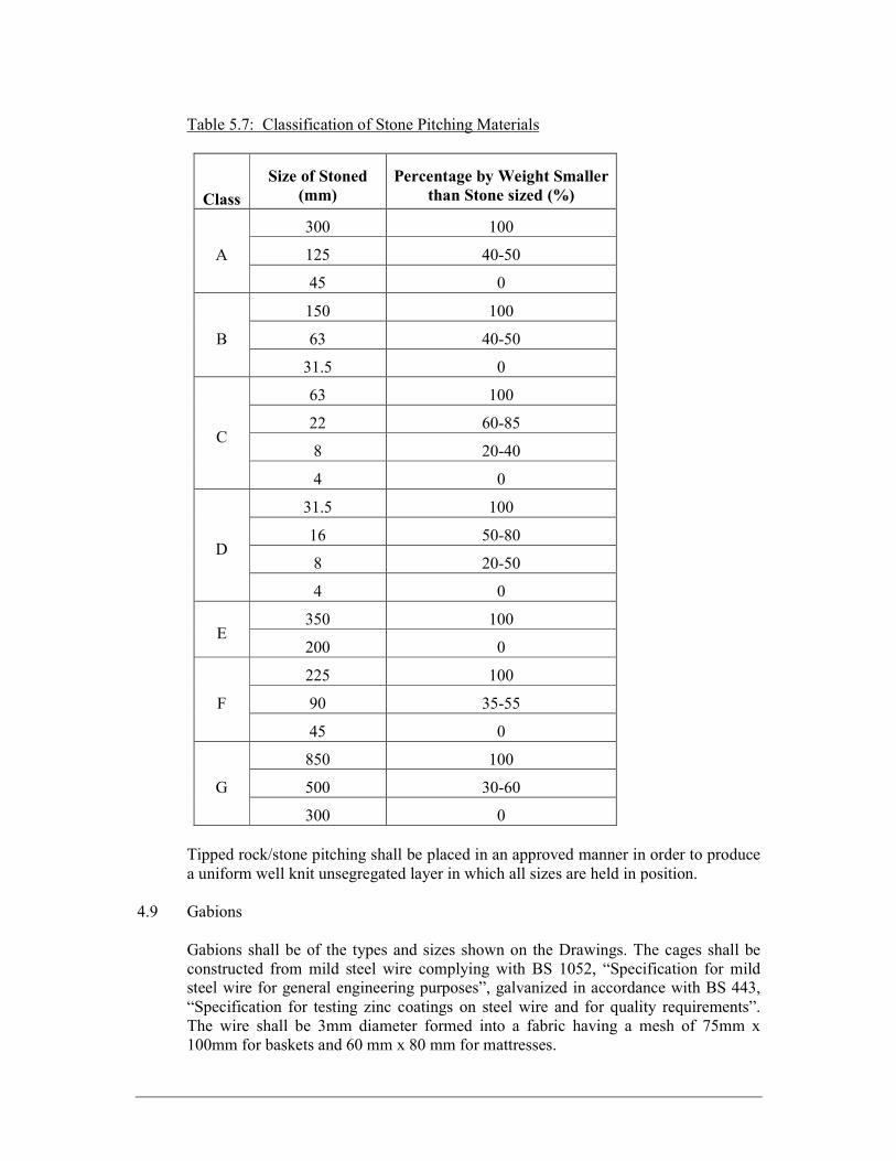
Table 5.7: Classification of Stone Pitching Materials
Class Size of Stoned
(mm) Percentage by Weight Smaller
than Stone sized (%) A 300 100 125 40-50 45 0 B 150 100 63 40-50 31.5 0 C 63 100 22 60-85 8 20-40 4 0 D 31.5 100 16 50-80 8 20-50 4 0 E 350 100 200 0 F 225 100 90 35-55 45 0 G 850 100 500 30-60 300 0 Tipped rock/stone pitching shall be placed in an approved manner in order to produce a uniform well knit unsegregated layer in which all sizes are held in position. 4.9 Gabions Gabions shall be of the types and sizes shown on the Drawings. The cages shall be constructed from mild steel wire complying with BS 1052, “Specification for mild steel wire for general engineering purposes”, galvanized in accordance with BS 443, “Specification for testing zinc coatings on steel wire and for quality requirements”. The wire shall be 3mm diameter formed into a fabric having a mesh of 75mm x 100mm for baskets and 60 mm x 80 mm for mattresses.
Stone filling for gabions shall consist of hard durable rock, free from weathered or decomposed parts. The minimum dimensions of each stone shall not be less than half its maximum dimension. For mattresses the stone shall be 200mm to 150mm for baskets the stone shall be 300mm to 200mm. The stone shall be obtained from a source approved by the Engineer. No stone shall be smaller than the size of the gabion mesh. In carrying out the filling, selected pieces of stone of elongated shape shall be placed with their flatter and elongated faces in contact with the mesh wherever possible. The empty gabions shall be placed to line and level as shown on the Drawings or as directed by the Engineer and then stretched so that the gabions regain their shape on being filled. Diaphragms shall be provided at not more than 1m intervals for baskets and not more than 0.6m intervals for mattresses. A gabion shall not be completely filled until the adjacent basket or mattress has been half filled, unless otherwise directed, in order not to cause displacements from bulging during filling. For baskets at least two horizontal connection wires shall be tied between front and back of the gabion in each 1m compartment, at a height of 300mm and 600mm from the bottom as the stone fill reaches these levels. Additional tie wires shall be provided if necessary and in no case shall the gabion basket bulge by more than 40mm. Where a continuous line of gabions is required, adjacent gabions shall be securely tied together at the top and bottom of the gabions with tying wire. The gabions shall be filled to a level just sufficient to require the lid to be forced into place with a bar. The lid and all joints between baskets and between diaphragms and baskets shall each be tied down with a continuous running wire. Where gabions are to be shaped, the shape shall be formed by folding the mesh internally and tying it with a continuous running wire. All tying wire shall be galvanized and of same gauge as specified for the cages above. The surface upon which gabions are to be laid shall be compacted to a minimum dry density of 95% of the maximum dry density (AASHTO T99). 4.10 Geotextile Filter Cloth Geotextile filter cloth shall be made of non-woven polyester material with a minimum weight of 270g/m2 and minimum thickness of 2.3mm. The material shall be placed carefully on suitably cleared surfaces, such that tearing or piercing is avoided at all times. Continuity at horizontal and vertical joins shall be achieved with a minimum overlap of 0.6m. Overlaps may be physically sealed using spot welds with an open flame and subject to approval of the Engineer. On a horizontal join, the new layer shall be
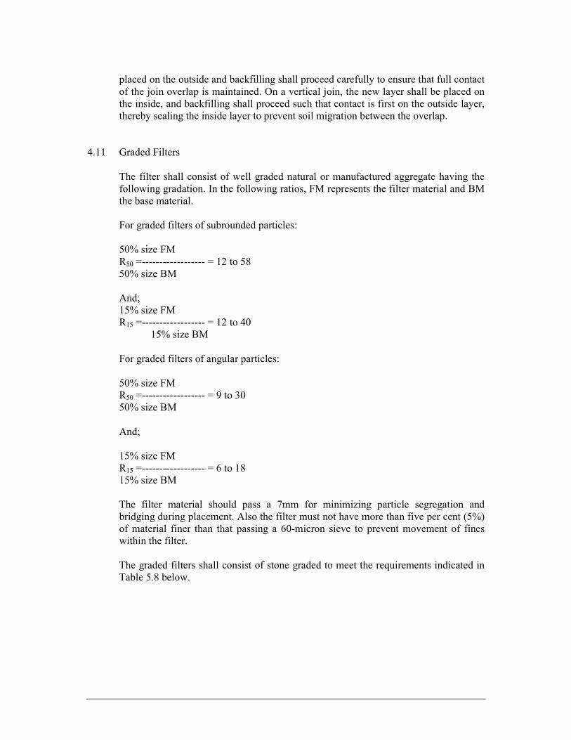
placed on the outside and backfilling shall proceed carefully to ensure that full contact of the join overlap is maintained. On a vertical join, the new layer shall be placed on the inside, and backfilling shall proceed such that contact is first on the outside layer, thereby sealing the inside layer to prevent soil migration between the overlap. 4.11 Graded Filters The filter shall consist of well graded natural or manufactured aggregate having the following gradation. In the following ratios, FM represents the filter material and BM the base material. For graded filters of subrounded particles: 50% size FM R50 =------------------ = 12 to 58 50% size BM And; 15% size FM R15 =------------------ = 12 to 40 15% size BM For graded filters of angular particles: 50% size FM R50 =------------------ = 9 to 30 50% size BM And; 15% size FM R15 =------------------ = 6 to 18 15% size BM The filter material should pass a 7mm for minimizing particle segregation and bridging during placement. Also the filter must not have more than five per cent (5%) of material finer than that passing a 60-micron sieve to prevent movement of fines within the filter. The graded filters shall consist of stone graded to meet the requirements indicated in Table 5.8 below.
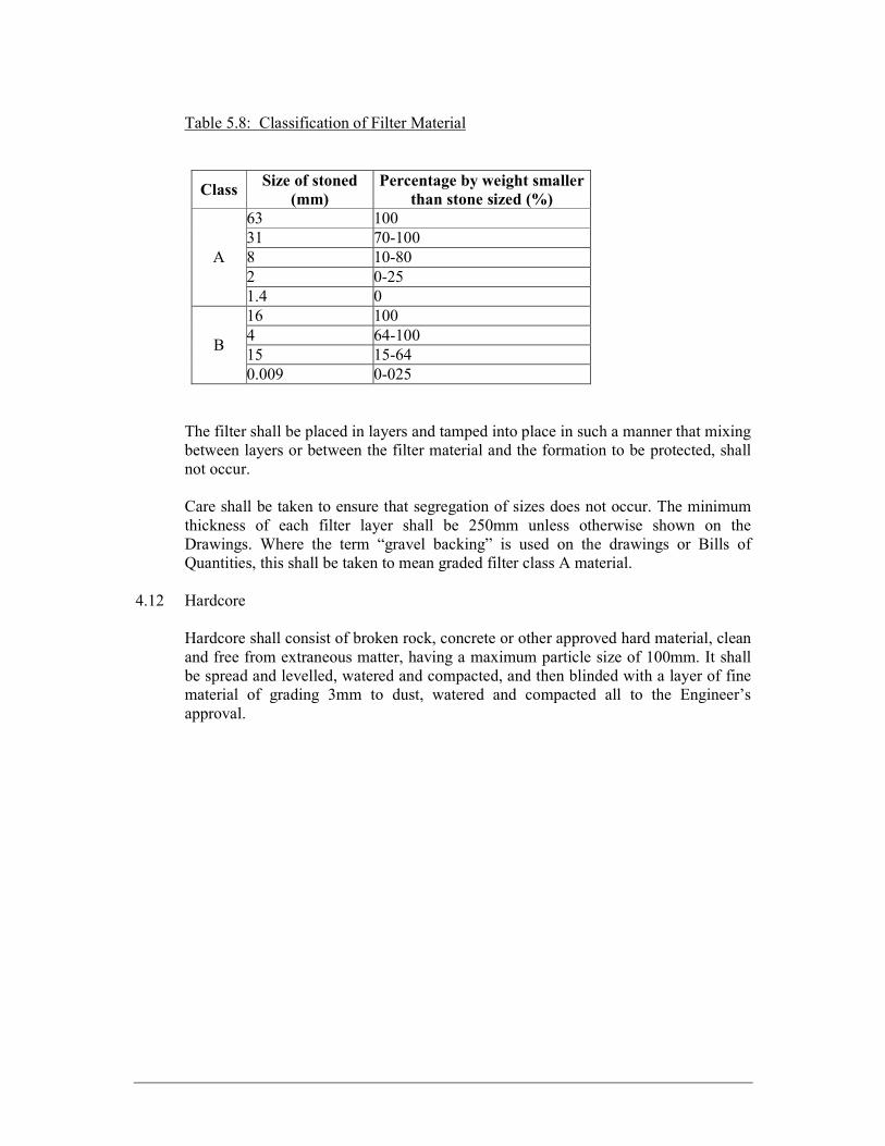
Table 5.8: Classification of Filter Material Class Size of stoned
(mm) Percentage by weight smaller
than stone sized (%) A 63 100 31 70-100 8 10-80 2 0-25 1.4 0 B 16 100 4 64-100 15 15-64 0.009 0-025 The filter shall be placed in layers and tamped into place in such a manner that mixing between layers or between the filter material and the formation to be protected, shall not occur. Care shall be taken to ensure that segregation of sizes does not occur. The minimum thickness of each filter layer shall be 250mm unless otherwise shown on the Drawings. Where the term “gravel backing” is used on the drawings or Bills of Quantities, this shall be taken to mean graded filter class A material. 4.12 Hardcore Hardcore shall consist of broken rock, concrete or other approved hard material, clean and free from extraneous matter, having a maximum particle size of 100mm. It shall be spread and levelled, watered and compacted, and then blinded with a layer of fine material of grading 3mm to dust, watered and compacted all to the Engineer’s approval.
5. PIPEWORK 5.1 General The Contractor shall construct pipelines to the lines and levels using grades, classes, or designs of pipe, bedding, haunching and surrounding as shown on the Drawings or directed by the Engineer. Unless otherwise described in the Contract or agreed by the Engineer only one type of pipe shall be used within any individual length. All materials shall be subject to the approval of the Engineer prior to procurement and delivery. Upon delivery, the Engineer shall inspect the delivered material for compliance with the specifications. In case of non-conformity, the Contractor shall replace the material at his own cost. The pipes and fittings shall comply in all respects with British Standards and jointing of pipes and fittings shall be carried out in accordance with the manufacturers’ instructions and to the approval of the Engineer. 5.2 Storage and Protection of Materials Pipes shall be stacked on a firm base using two timber packers only under the barrel of rigid pipes such as concrete. Flexible pipes such as PVC-U shall be stacked closely side by side on a firm plane base so that the whole length of the barrel is uniformly supported and sockets are clear of the ground. Each succeeding layer shall be placed at right angles to the previous layers. The height of any stack shall be not more than six layers of pipes and in the case of steel, not more than two layers. Each class and size of pipe shall be stored separately in its own stockpile. Fittings and specials of any type shall be stored in a single layer only. Pipes and fittings shall at all times be adequately protected from damage during transport, storage and handling. Cracked or chipped pipes shall not be used in the permanent works. Steel and large diameter plastic pipes shall be fitted in the factory with end caps or reinforcement adequate to prevent distortion during transport, storage and handling. Plastic pipes and fittings shall be protected from direct sunlight and excessive heat. Deformed pipes and fittings shall not be used in the permanent works. All rubber rings or other materials that may deteriorate under the action of sunlight, ozone or inclement weather shall be stored in permanent shade in lockable weatherproof sheds. Care shall be taken at all times to prevent contamination of rubber or plastic products or other petroleum-derived solvents.

Granular bedding shall be stored on a firm impermeable base so that it does not become contaminated with deleterious matter. 5.3 Handling Pipes and Fittings Before any pipes are delivered to site the Contractor shall submit details to the Engineer of his proposals for handling pipes during transport, in store and during lying. Pipes and specials shall only be transported on properly constructed or adapted vehicles containing correctly shaped and padded cradles or with strong, sawdust-filled bags separating pipes and vehicle body. During transport and in store, pipes shall not rest on narrow traverse supports likely to cause damage to the pipe or its coating. Pipes shall not be unloaded from a vehicle by tipping or dropping. Pipes, specials and fittings shall not be subjected to rough handling at any time. Under no circumstances shall they be dropped during loading or off-loading or be allowed to collide with one another. Any materials that have been dropped from a vehicle shall immediately be rejected for use on the Works. The same shall apply for any pipes found defective before laying. The handling of any pipes exceeding 200kg mass other than by means of a crane is specifically forbidden. The Contractor shall maintain a suitable mobile crane on the Site and shall use it for all loading, unloading, transferring between vehicles and lowering into the trench of such pipes. The crane shall be fitted with a sling of ample width. Wire rope slings or hooks in the ends of pipes shall not be used for pipes or fittings of any diameter or mass. In making arrangements for handling pipes, the Contractor shall take into account any recommendations made by the pipe manufacturer. Where appropriate the requirements of this Clause shall apply to fittings and other components. 5.4 Cutting Pipes The cutting of pipes for making up lengths shall be carried out by a method, which leaves a clean square end. Concrete pipes shall be cut with a concrete saw or by hand. If cut by hand the end of the pipes shall be trimmed even and square and if reinforced, the steel shall be cut flush with the face of the concrete. If instructed by the Engineer the exposed ends of the steel shall be protected with bitumen or a cement grout. Steel pipes to be cut shall have the line to be cut clearly marked round the pipe. Cutting shall be carried out by cutting disc or by oxy-acetylene and the cut end shall subsequently be ground to the correct profile for the method of jointing in use.

5.5 Pipes and Fittings 5.5.1 Concrete Pipes Concrete pipes shall comply with BS 5911 “Specification for concrete cylindrical pipes, bends, junctions and manholes, unreinforced or reinforced with steel cages or hoops” save that the crushing test loads for the various diameters of pipe shall be as follows: Table 5.9: Pipes and Fittings Nominal size of pipe (mm) Works proof load kN/m effective length 300 23 (Class M equivalent) 450 35 (Class M equivalent) 600 46 (Class M equivalent) 800 54 (Class M equivalent) 900 85 (Class M equivalent) 1000 73 (Class M equivalent) 1200 110 (Class M equivalent) 1500 132 (Class M equivalent) Works proof loads shall be 80% of the maximum loads for each size of pipe. Damaged pipes showing signs of visible cracking either on the inside or outside surface shall not be used. 5.5.2 Steel Pipes
Steel pipes and fittings shall comply with BS EN 10224:2003 Non-alloy steel tubes and fittings for the conveyance of aqueous liquids including water for human consumption – technical delivery conditions. Pipe shall be either seamless, electric welded or submerged arc welded. However the manufacturing process shall not be beyond their allocated diameter ranges: Table 5.10: Steel Pipes Manufacturing process Outside diameter
range, mm Thickness range, mm Seamless (S) 26.9 – 711 2.0 – 100 Electric Welded (EW) 26.9 – 610 1.4 – 16 Submerged Arc Welded (SAW) 168.3 - 2743 2.9 - 50 Seamless (S) pipe is formed by a method of hot working steel to form a tubular product without a welded seam. If necessary, the hot worked tubular product may be subsequently cold finished to produce the desired shape, dimension and properties.
Electric Welded (EW) pipe formed continuously from a steel strip with a longitudinal seam. This seam is joined by electric resistance or electric induction welding wherein the edges to be welded are mechanically pressed together and the heat for welding is generated by the resistance to flow of the electric current. Submerged Welded pipe (SAW) formed from a steel strip with a longitudinal or helical (spiral) seam. The seams are then welded together by a coalescence of metals caused by heating them with an arc or arcs between a bare consumable electrode or electrodes. The arc and molten metal are shielded by a blanket of granular, fusible material on the work. Welding shall include at least one pass on the inside and one pass on the outside of the pipe. Pipes shall not include welds used for joining lengths of steel strip together prior to forming except for helical welded pipe provided that such weld is made using the same method of welding as the helical seam. Pipes shall not contain circumferential welds. Pipes shall not be manufactured on site. Pipes formed from, plate, strip or coil shall have edges mechanically sheared before forming. In the case of pipes thicker than 10mm to be manufactured by the Submerged Arc Process (SAW), the edges of plate, strip or coil shall be chamfered by mechanical milling. Pipe shall be delivered in 12m exact lengths for DN 250 and above and 6m exact lengths for DN 200 and below. The tolerances on pipe length shall be in accordance to Table 9 of BS EN 10224. Unless otherwise specified, pipe shall be supplied with spigot and socket push-fit joints with elastomeric seals. The joints shall be flexible joints as defined in BS EN 805:2000 and the allowable angular deflection of the joints shall comply with the Class B limits given in Table 5 of EN 805. Steel pipes and fittings larger or equal to DN 200 shall be internally lined throughout their entire length internally with either: (a) Fusion bonded epoxy to AWWA C213 (400 µm dry film thickness); (b) Solvent free liquid epoxy to AWWA C210 (400 µm dry film thickness); (c) Polyurethane to AWWA C222 (500 µm dry film thickness). The materials and application process shall be subject to the Engineer’s approval. Steel pipes and fittings smaller or equal to DN 150 may be lined in cement mortar to AWWA C205. For steel pipes DN 500 and below, the external protection shall be fusion-bonded epoxy to AWWA C213.

Dimensions for fittings shall comply with BS EN 10224. In the case of fittings such as reducers, laterals and washout tees not covered in BS EN 10224, the dimensions shall comply with AWWA C208. Calculation of thickness of bends and reinforcement of tees and laterals shall comply with AWWA C208 and AWWA M11. The Contractor shall submit details of such calculations. Flange jointed pipes shall have flanges complying with BS EN 1092: 2002. All steel flanged pipes and fittings shall be supplied complete with hot dipped galvanized bolts, nuts to BS EN ISO 1461 (minimum 305g/m2) and appropriate gaskets. Gaskets shall be EPDM rubber and conform to BS EN 681. They shall be suitable for potable water. The Contractor shall make available to the Engineer the manufacturer’s certificates covering the chemical analysis and physical properties of each cast of steel used in the manufacture of pipes. In addition, a product analysis shall be conducted on the steel coils, plates, billet or blanks prior to pipe manufacture. All pipes shall be hydraulically tested before leaving the factory to induce a hoop stress equal to 70% of the minimum yield stress pressure as specified in BS EN 10224. All pipes shall be tested according to Table 14 of BS EN 10224 and at the frequency stipulated in Table 15. All tests shall be carried at the expense of the Contractor at the place of manufacture and the Contractor shall supply a signed certificate on delivery of the goods concerned giving results of the tests and certify that the goods concerned have been manufactured in accordance with this Specification. 5.5.3 Galvanized Steel Tubes Galvanized mild steel tubes and fittings shall comply with BS 1387 Class B or “Medium Grade”. Threading for screwed and socketed joints shall be in accordance with the requirements of BS 21. Joints shall be made with an approved pipe-jointing compound in accordance with the manufacturer’s instructions. Red lead compounds shall not be used. Joints in underground piping shall be coated with bitumen or other approved composition. All underground sections of pipe work to be protected against corrosion by treating with K1-60 bitumen emulsion primer, and wrapped with fibreglass and coated with two coats of bituminous tap coats all to manufacturer’s specification. The bituminous paint is to be manufactured to ASTM D1187-82.
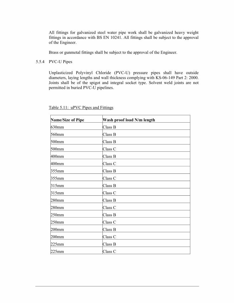
All fittings for galvanized steel water pipe work shall be galvanized heavy weight fittings in accordance with BS EN 10241. All fittings shall be subject to the approval of the Engineer. Brass or gunmetal fittings shall be subject to the approval of the Engineer. 5.5.4 PVC-U Pipes Unplasticized Polyvinyl Chloride (PVC-U) pressure pipes shall have outside diameters, laying lengths and wall thickness complying with KS-06-149 Part 2: 2000. Joints shall be of the spigot and integral socket type. Solvent weld joints are not permitted in buried PVC-U pipelines. Table 5.11: uPVC Pipes and Fittings
Name/Size of Pipe Wash proof load N/m length 630mm Class B 560mm Class B 500mm Class B 500mm Class C 400mm Class B 400mm Class C 355mm Class B 355mm Class C 315mm Class B 315mm Class C 280mm Class B 280mm Class C 250mm Class B 250mm Class C 200mm Class B 200mm Class C 225mm Class B 225mm Class C

Fittings for use with PVC-U pressure pipe shall be manufactured from either PVC-U or cast iron with socketed joints and shall comply with ISO 727. Cast iron fittings shall be bitumen coated. Aluminium alloy fittings are not permitted. The metal adaptor fittings shall comply with ISO 4132. 5.5.5 PE Pipes Polyethylene (PE) pipes and fittings shall comply with ISO 4427:1996. 5.6 Valves 5.6.1 Gate Valves Gate valves shall conform to BS 5153-1:2004. The valves shall be tested in accordance with BS EN 1074-2:2000. Non-return valves BS EN 1074-3:2000 Air valves BS EN 1074-4 :2000 Hydrants BS EN 1074-6 :2004 All gate valves shall close in a clockwise direction and the direction of opening and closing shall be cast on the hand wheels or valve casing with the words ‘OPEN’ and ‘CLOSE’ respectively. All gate valves shall be capable of being operated manually with a maximum applied torque of 100 Nm for valves with a nominal diameter less than 450mm. The Contractor shall ensure that the gate valves supplied are fitted with appropriate thrust bearing guides and gearing to fulfill these requirements, ensuring that when reduction gearing is employed, the gear ratio shall not exceed 4:1. Isolating gate valves shall permit manual closing off the raw water supply. 5.6.2 Butterfly Valves Butterfly valves shall conform to BS EN 593:1998: “Industrial valves. Metallic butterfly valves.” The valves shall be tested in accordance with BS EN 1074-2:2000. The use of butterfly valves as main line valves shall not be permitted. 5.6.3 Check Valves Check valves shall comply with BS EN 12334:2001: “Industrial valves. Cast iron check valves.” The valves shall be tested in accordance with BS EN 1074-3:2000. The valves shall be installed in a horizontal position to avoid malfunctioning of the check. 5.6.4 Single Air Valves

Single air release valves shall be of the small orifice type and shall have bodies of cast iron. The inlet shall be 25mm diameter fitted with an isolating plug cock and shall be screwed in an 80mm diameter blank flange drilled and tapped to BS 21. Single air valves shall be of pattern and manufacture approved by the Engineer for the conditions under which they will operate, and be fitted with a pressure gauge tapping and plug. Floats are to be manufactured from high-density polyethylene. The valves shall be tested in accordance with BS EN 1074-4:2000. 5.6.5 Double Air Valves Air release and vacuum break valves shall be of a compact, single chamber design with solid cylindrical high density polyethylene control floats housed in a tubular stainless steel body with stainless steel ends secured by stainless steel tie rods. The valves shall have integral surge alleviation mechanisms that shall operate automatically to limit transient pressure rise or shock induced by closure due to high velocity air discharge or the subsequent rejoining of separated water columns. The limitation of pressure rise must be achieved by deceleration of approaching water before valve closure. The intake/discharge orifice area shall be equal to the nominal size of the valve. The valve design shall incorporate an overpressure safety feature that will fail without an explosive effect. This feature shall consist of easily replaceable components such as gaskets, seals or the like. The valves shall be tested in accordance with BS EN 1074-4:2000. 5.6.6 Flow Control Valves Pressure and flow control valves shall be installed as shown on the Contract Drawings and be suitable for the operating conditions specified. The basic valves shall be either of the pressure compensating globe valve design with externally arranged spring and diaphragm assembly or of the streamline two chamber concentric plunger and pilot valve regulating assembly enclosed within the valve body as required for the particular applications. Valve bodies shall be of a suitable grade of close-grained cast iron to BS EN 1561:1997. Valves shall be sized such that the fully open capacity is more than adequate to accept the specified maximum flow at the minimum differential pressure. The globe valve design shall have the main seat in the stream flow and an upper cylinder for the valve element control piston type and shall have the required number of bosses drilled and tapped to receive strainer unit, relay valves and pressure gauges. The cover plate shall include an air vent and lifting eyes. The main seat shall have a

renewable element and the upper portion shall be in the form of a piston and the lower portion shall have a face ring and ported guide. Valves shall be fitted with an external control relay system which shall be capable of controlling the required parameter of flow or pressure within + or -5 per cent of the set value. The relay system shall include connecting piping couplings and isolating valves to permit maintenance or replacement without interrupting supply. The rate of response of opening and closing of the main valve shall be adjustable and means for external indication of the main valve element position shall be fitted. The particular control system for the different duties shall be as specified below. a) Altitude Valves The main valve shall be controlled by a slave ball cock mounted in the controlled tank at top water level and connected to the valve operating mechanism by small-bore pipe work. The level of the ball shall be adjustable in service so that the main valve is fully drop-tight closed when the water level in the tank reaches top water level. b) Flow Control Valves Flow control valves shall be designed to prevent the flow downstream rising above that specified in the Particular Specification or shown on the Drawings for the particular application, regardless of the operating pressures in the system upstream or downstream of the valve. The relay system valve shall be operated by the pressure differential measured across the main flow orifice, which shall be fitted at the upstream end of the flow control valve. c) Pressure Reducing Valves Pressure reducing valves shall be designed to reduce a constant or variable inlet pressure to a predetermined constant outlet pressure, at flows varying from the maximum capacity of the valve to zero flow. Adjustment of the outlet pressure shall be made by a screw on the relay valve or by changing weights as appropriate. A pressure gauge indicating downstream pressure shall be incorporated. d) Pressure Sustaining Valves Pressure sustaining valves shall be designed to maintain the pressure in the pipeline immediately upstream of the valve at or above a preset value, irrespective of the flow and pressure conditions downstream of the valve. Adjustment of the upstream pressure shall be made by a screw on the relay valve or by changing weights as appropriate. A pressure gauge indicating upstream pressure shall be incorporated. e) Pressure Relief Valves
Pressure relief valves shall be designed to prevent the pressure in the pipeline immediately upstream of the valve rising above a preset value. The valve shall remain closed at lower pressures. Adjustment of the pressure at which the valve opens to relieve pressure shall be made by a screw on the relay valve or by changing weights as appropriate. A pressure gauge indicating upstream pressure shall be incorporated. 5.6.7 Float Valves Float operated valves shall comply with BS 1212 and BS 1968 and BS 2456 “specifications for float ball valves”. Ball valves shall be the plastic diaphragm type or similar approved with seatings to suit the working pressure of 5 bars with plastic float to BS 2456 and internal overflow. 5.6.8 Painting of Valves All valves shall be painted internally and externally to give the same standard of protection as for steel pipes and fittings. Surface protection shall be all to the approval of the Engineer. 5.7 Laying Pipes in Trenches and Headings Immediately before pipes are placed in any trench, the bottom shall be cleared of all stones and other debris and shall be in a condition acceptable to the Engineer. Prior to placing in the trench, all pipes shall be inspected for damage. Damaged pipes which in the opinion of the Engineer cannot satisfactorily be made good shall not be used in the permanent works. End caps or discs placed on the pipes for protection during transit shall not be removed until immediately before the pipes are jointed. Pipes shall be laid in straight lines unless otherwise shown on the drawings. No pipe shall deviate from the true line and level by more than 5mm. Pipes shall be firmly bedded throughout their length to the required alignment and level so that they are concentric at each joint. All pipes shall be suitably wedged, shored or otherwise restrained to prevent movement during testing and backfilling but such restraints shall not be left in place permanently unless instructed or agreed by the Engineer. Pipes which are to receive a concrete bed and hauch or surround shall be set on suitable concrete blocks or bricks with a pad of hessian based damp proof course two millimetres thick interposed between the pipe and the block. Setting blocks shall not be used with other forms of bedding. Unless otherwise agreed by the Engineer a close fitting brush or swap shall be placed in pipelines having nominal diameters of 650mm or less and shall be drawn forward progressively as pipelaying proceeds by means of a suitable rope which shall be threaded through each pipe as it is laid. Pipelines having nominal diameters greater than 650mm shall be kept clean by suitable means as pipelaying proceeds. No debris

of any kind shall be allowed to remain in the pipeline. Where the pipeline has internal lining, persons entering shall wear rubber boots and equipment trolleys shall have rubber tyred wheels. Pipes and joints shall be kept free of dirt, mud and other deleterious matter at all times. If pipelaying is stopped at any time, a cap shall immediately be placed on the end of the last pipe laid to exclude dirt. Suitable precautions shall be taken to prevent the floating of pipes due to flooding of trenches. If floating should occur, the whole of the pipe run affected shall be removed and trench prepared again. No pipes shall be re-laid in trenches which have flooded until the trenches and the pipes have been inspected by the Engineer. The Contractor shall be entirely responsible for the sufficiency of all temporary supports and side slopes to the excavations. The excavation shall be carried out in such a way as to maintain the stability of all roads and other adjacent structures or works. Pipes having integral sockets shall be laid with sockets facing upstream unless otherwise agreed or instructed by the Engineer. Pipes in headings shall be laid in accordance with the requirements of this clause but pipe lengths shall not exceed 2.5 m unless otherwise agreed by the Engineer. 5.8 Pipes Laid on Natural Ground Filling shall commence with selected fill consisting of easily compacted material from which all stones larger than 25mm and all lumps of clay larger than 75mm have been removed. The selected fill shall be deposited equally on each side of the pipe carefully compacted in layers not more than 150mm thick. Care shall be taken to ensure that no voids are left under the pipe. The filling shall be continued to a level of 300mm above the crown of the pipe In the case of steel, ductile iron and plastic pipes, the Contractor shall ensure that no distortion of the pipe takes place during the backfilling operation. The remainder of the trench shall be filled with excavated material and compacted in 150mm thick layers by means of a vibrating plate compactor or a mechanical rammer. The trench shall be filled flush with the surrounding ground surface. 5.9 Pipes Laid on Granular Bedding Granular bedding material shall be placed and compacted generally on both sides of the pipe up to the horizontal diameter of the pipe. Care shall be taken to ensure that no voids are left under the pipe. Thereafter the selected fill shall be as described in Clause 5.8 above. 5.10 Pipes with Concrete Bedding and Surround The configuration of the concrete bedding, surround or arch shall be as shown on the drawings including the location of reinforcement if any is required. Pipes to be set in concrete shall be supported as set out in Clause 5.7. Small diameter pipes in short
lengths shall be supported behind pipe socket. Large diameter pipes and long lengths shall be supported on two packers. After jointing and testing as set out in the appropriate parts of this section, concrete of the class shown on the drawings shall be carefully placed and compacted under the pipes making sure that no voids are left, and brought up to the configuration shown on the drawings. The Contractor shall ensure that the pipes do not float or are in any way disturbed during concrete placing. The remainder of the backfill shall be placed as set out in Section 2 of this Specification. Where pipes, which are laid on a bed of granular material, are to be protected by a concrete arch, the laying and jointing shall proceed as set out in the appropriate parts of the Specification and granular material shall be brought up to the horizontal diameters of the pipes. After testing, concrete shall be placed over the pipes to the configuration shown on the drawings and the remainder of the backfill shall hereafter be placed as set out in Section 2 of this Specification. Flexible joints shall be formed in concrete beddings, arches or surrounds in the location shown on the drawings. Such joints shall coincide with the pipe joint in such a way that the end of the socket is flush with one face of the joint and the socket faces into the joint space. Joints in concrete beddings, arches and surrounds shall be 18 mm wide unless otherwise instructed by the Engineer and shall be filled with a compressible material such as a sheet of cane fibre board or cork board. The material used shall be subject to the approval of the Engineer. 5.11 Special Accessories for the Buried Pipe Network 5.11.1 Scope This section of the specification concerns the supply and installation of accessories for the buried pipe network at the locations shown on the approved Drawings or as directed by the Engineer. The several parts of the accessories, as described below, shall be considered as a complete unit, which will serve to supply water to the hydrant outlets from the underground distribution network. Each part shall be fabricated by an internationally recognized manufacturer and shall conform to the conditions of operation, the characteristics, the testing and other requirements described below. The several parts of the accessories, as described below, shall be considered as complete unit, which will serve to supply water to the hydrant outlets from the underground distribution network. Each part shall be fabricated by an internationally
recognized manufacturer and shall conform to the conditions of operation, the characteristics, the testing and other requirements described below. The Contractor shall at the time and place required, submit to the Engineer proposals concerning the manufacturers selected by him for the supply of the accessories, accompanied by a detailed report, specifications and certificates showing that the proposed components have been successfully used in similar sprinkler systems, so as to prove that the proposed accessories conform to the requirements of this specification in a satisfactory manner. Subsequent to the provision and acceptance of the proposals as above, the Engineer may agree to the use of the proposed accessories, but his consent cannot be interpreted in any case whatsoever, as relieving the Contractor of his responsibilities for the supply of accessories which shall prove adequate and efficient during the testing procedure and the operation of the network. The Engineer reserves the right, on the other hand to reject the Contractor’s proposals if he finds them incomplete or vague or if the proposed accessories do not conform to the requirements of this specification. In such a case, within a reasonable period, not longer than one month, after communication of the above decision of the Engineer to the Contractor, the latter is required to supplement and improve his original proposals and submit his revised recommendations. If the Contractor fails to submit, within the above time limit, his final recommendations, or if the Engineer for the same reasons rejects these for which his original proposals were rejected, he is required to supply accessories, which will satisfy the Engineer. If, however, he does not agree and insists on supplying the accessories which he has proposed, he must deposit a guarantee to an amount equal to the value of these accessories. This guarantee will remain in the hands of the Employer until the final acceptance and will be forfeited to the latter if, during the test procedure and the operation of the network, it is ascertained that the accessories supplied by the Contractor are not satisfactory. It is understood that the Contractor is, in addition, required to fulfill all his other obligations for the restoration of all defective construction until final acceptance by the Engineer. 5.11.2 Acceptance Tests Included with the specifications submitted by the Contractor, shall be copies of any relevant international standards to which the items are to be constructed. The Engineer reserves the right to request independent authenticated tests at the point of manufacture and also similar tests in situ under operating conditions. All costs shall be borne by the Contractor who will promptly replace any components which, in the judgement of the Engineer are found, either after testing or during operation and until final acceptance, as not conforming to the requirements of this Specification. 5.11.3 Measurement and Payment
Measurement shall be by assessing the number of satisfactorily installed and accepted accessories. Payment will be made for the number of accessories measured as described above and based on the respective contract unit prices. Such prices and payment constitute full compensation to the Contractor for supplying, hauling, storing and installing the accessories, for paying patent rights, for furnishing the equipment, materials and labour required for installing and checking the operation of the accessories in accordance with the foregoing requirements, and for any other related expense even if not explicitly stated above but necessary for the complete and proper performance of the work and the satisfactory operation of the accessories. 5.11.4 Irrigation Hydrants There are generally two types of hydrants as shown on the Drawings: • Type 1 Plot hydrant • Type 2 Field hydrant 5.11.5 Pressure Reducing Valves There is a requirement for Pressure Reducing Valves, which will protect the installed pipelines against high pressures. The Contractor shall submit to the Engineer proposals referring to the valves to be used and the name of the manufacturer with whom he intends to place the purchase order, accompanied by a detailed report, specifications and certificates showing that the proposed valves have been successfully used in similar cases so as to prove that the proposed valves conform to the requirements of this specification in a satisfactory manner. Following completion of the construction of the pipe network, and prior to its final acceptance, the engineer may demand the performance of tests to ascertain the efficiency and adequacy of the installed valves. To this effect, the Contractor shall, at his own expense, place at appropriate locations of the network to be designated by the Engineer automatic recording manometers with the minimum possible inertia of moving parts so as to ascertain in an unquestionable manner, the adequacy of the valves, especially during filling and draining of the network as well as on sudden opening and immediate shut down of a riser located at a relatively unfavorable point. The Contractor shall take into account the fact that the valves must be” drop tight” or “sealed” at no flow conditions and that the seals and operating mechanisms must be proof against suspended solids in the supply water (untreated river water). The valves shall operate automatically, hydraulically, without electricity.
5.12 Joints in Pipelines 5.12.1 Concrete Pipes Rigid Joints When laying rigidly jointed pipelines with pipes having integral sockets, before entering a pipe spigot into its socket, both spigot and socket shall be clean and free from mud, oil, grease or other deleterious matter. A gasket of tarred hemp yarn, cut to length so that it forms a butt joint at the crown of the pipe shall be wrapped round the spigot which shall then be fully entered into the socket and the gasket caulked up hard into the joint. The joint shall then be filled completely with a plastic mortar composed of one part of cement to two parts of sand. The pipes shall not be pressure tested or disturbed in any way for at least 48 hours after jointing. Rigidly jointed sleeves used to join two spigots shall be jointed in the same manner as integral sockets. If the drawings require ogee jointed pipes to be laid with a mortar joint, the joint shall be made at the time of laying. Mortar as described above shall be applied to the lower semi-circumference of the socket and to the upper semi circumference of the spigot and the pipe shall be drawn hard into the socket. Excess mortar squeezed out of the joint shall be removed from both the inside and outside of the joint. Flexible Joints Flexible joints between pipes having integral socket may be formed by a shaped rubber gasket fitted within the socket or by a rubber ring of circular cross section (O-ring) placed on the pipe spigot. The type of flexible joint to be used shall be subject to the approval of the Engineer and shall be made strictly in accordance with the manufacturer’s recommendations. 5.12.2 PVC-U Pipes Flexible jointed PVC-U pipes shall be jointed in accordance with the manufacturer’s instructions. Solvent welded joints shall be made strictly in accordance with the manufacturer’s instructions using solvent supplied by him for exposed pipes. 5.12.3 Steel Pipes These shall be caulked in thread seal for rigid joints. Flexible joints incorporating rubber O-rings shall be made in accordance with the manufacturer’s instructions. Joints incorporating bolted or screwed glands or couplings shall be made in accordance with the manufacturer’s instructions.
Components of flexible joints from different manufacturers shall not be used together. 5.13 Connections to Existing Pipelines Where a connection is to be made to an existing water pipe other than that at a chamber, a pipe saddle of the correct size shall be used for this purpose. The hole in the pipe shall be cut precisely to fit the saddle. Saddles for uPVC pipes shall be made of the same material as the pipes and shall be fixed with a solvent in accordance with the manufacturer’s instructions. 5.14 Pipes through Structures Where a pipeline passes into or out of a structure, including a manhole cover or similar chamber, two flexible joints shall be formed. The flexible joint shall consist of a 500mm long pipe section connected along the main pipe, with the nearest end 500mm from the face of the structure. One joint will be made on the incoming pipe and another joint on the outgoing pipe. When the structure is less than one pipe length wide, the above requirement shall not apply and a sleeve shall be formed through the structure so that there is a clear space at least 75mm wide all round the pipe. Adequate means shall be provided to prevent soil from entering this gap. 5.15 Pipelines within Concrete Structures Sections of pipelines which are to be cast into concrete may be installed in advance of the remaining parts of the pipeline subject to the agreement of the Engineer. Such sections shall be placed accurately into position and fixed so that they cannot move during placing of concrete around them. 5.16 Pipes under Roads All pipes at the crossing of driveways and roads shall be surrounded with concrete for the entire length of crossing before trench backfilling. Concrete surround shall be approved by the Engineer on satisfactory compliance with protection of pipes as detailed in Section 5.9. 5.17 Cleaning The insides of all pipes, valves, tanks and fittings shall be clean, smooth, and free form blister, loose scale and dirt when erected. All lines shall be cleaned after all installation work. When pipes are installed, all ends shall be suitably plugged until final fixing of fixtures can be carried out. Pieces of cloth or stone will not be permitted.

5.18 Pressure Testing of Pipelines As the installation of the pipe work proceeds, the various sections shall be tested before they are built in, concealed, or finally connected. The Contractor shall advise the Engineer in writing at least three days in advance of the carrying out of such tests, and such tests shall, if considered necessary by the Engineer, be carried out in his presence. All tests shall be at the expense of the Contractor and it shall be the responsibility of the Contractor to make all necessary records of the tests and results and submit these to the Engineer in the final form agreed. All pipe systems shall be tested hydraulically for a period of one hour to not less than one and a half times the design working pressure. Testing shall comply with BS EN 805:2000 for standard field-testing of pipelines. If preferred, the Contractor may test the pipelines in sections. Any such section found to be satisfactory need not be the subject of a further test when the system has been completed, unless specifically requested by the Engineer. During the test, each branch and joint shall be examined carefully for leaks, any defects observed shall be made good by the Contractor, and the section re-tested. 5.19 Painting of Exposed Pipes and Fittings All metal surfaces within chambers shall be mechanically wire brushed to remove all loose scale, grease etc. Within two hours of cleaning, a primer shall be applied, followed after two hours by a first coat of heavy consistency bitumen paint all to the approval of the Engineer. A second coat of the heavy consistency paint shall be applied after 24 hours. The final coating thickness shall not be less than 250 microns. Preparation and application of the coating system shall be strictly in accordance with the Manufacturer's instructions. This clause shall not be applied to chemically or thermally bonded coatings on steel pipes. 5.20 Marker Posts Precast concrete marker posts shall be set in concrete and fixed near valves, fire hydrants, washouts, changes in direction of the mains and where directed by the Engineer. The posts shall be detailed as directed by the Engineer. 5.21 Portable Sprinkler Irrigation Equipment 5.21.1 Scope The Tender involves the supply of sprinkler irrigation equipment for overhead irrigation.
The contractor shall have submitted with his Tender detailed specifications as to the dimensions, type and materials utilized in sprinkler construction, together with any detail that the Contractor may consider relevant. The Contractor shall at the time and place required submit to the Engineer proposals concerning the manufacturers selected by him for the supply of the portable sprinkler-irrigation equipment accompanied by a detailed report, specifications and certificates showing that the proposed components have been successfully used in similar sprinkler systems so as to prove that the proposed equipment conforms to the requirements of this specification in a satisfactory manner. Subsequent to the provision and acceptance of the proposals as above, the Engineer may agree to the use of the proposed equipment, but his consent cannot be interpreted in any case whatsoever, as relieving the Contractor of his responsibilities for the supply of equipment which shall prove adequate and efficient during the testing procedure and the operation of the network. The Engineer reserves the right, on the other hand, to reject the Contractor’s proposals if he finds them incomplete or if the proposed equipment does not conform to the requirements of this specification. In such a case, within a reasonable period, not longer than one month, after communication of the above decision of the Engineer to the Contractor, the latter is required to supplement and improve his original proposals and submit his revised recommendations. If the Contractor fails to submit, within the above time limit, his final recommendations or if these are rejected by the Engineer for the same reasons for which his original proposals were rejected, he is required to supply portable sprinkler irrigation equipment which will supply the Engineer. If, however, he does not agree and insists on supplying the equipment which he has proposed, he must deposit a guarantee to an amount equal to the value of the equipment. This guarantee will remain in the hands of the Employer until the final acceptance and will be forfeited to the latter if during the test procedure and the operation of the network, it is ascertained that the portable sprinkler irrigation equipment supplied by the Contractor is not satisfactory. It is understood that the Contractor is, in restoration of all defective construction until final acceptance by the Engineer. 5.21.2 Acceptance Tests Included with the specifications submitted by the Contractor shall be copies of any relevant international standards to which the items are to be constructed. The Engineer reserves the right to request independent authenticated tests at the point of manufacture and also similar tests at the point of manufacture and also similar tests in situ under operating conditions. All costs shall be borne by the Contractor who will promptly replace any equipment which in the judgment of the Engineer is found, either after testing or during operation and until final acceptance, as not conforming to the requirements of this Specification.

5.21.3 Measurement and Payment Measurement shall be made by assessing the number of satisfactorily installed and accepted items of portable sprinkler irrigation equipment. Payment will be made for the number of items measured as described above and based on the respective contract unit prices. Such prices and payment constitute full compensation to the Contractor for supplying, hauling, storing and installing the equipment for paying patent rights for furnishing the equipment, materials and labour required for installing and checking the operation of the items in accordance with the foregoing requirements, and for any other related expense even if not explicitly stated above, but necessary for the complete and proper performance of the work and the satisfactory operation of the portable sprinkler irrigation equipment. 5.21.4 Portable Sprinkling Irrigation Equipment This equipment comprises the following as shown in the drawings: • HDPE pipes of 6 m lengths, 20 -25mm diameter and of class 4 (6 bar), • HDPE/GI adaptors, • GI equal tee, • 15mm diameter GI riser pipe with support (tripod or equivalent), • 15 mm sprinklers (double or single nozzle) to deliver on average 0.63m3/hr at between 15 – 40m heads and of highly durable material (not plastic) and corrosion resistant, Also, refer to sub-sections 5.21.1, 5.21.2 and 5.21.3. All equipment should be of recognized standards.

6. STEELWORK 6.1 General Except where otherwise specified, structural steel shall be grade 43, complying with BS 7668, “Specification for weldable structural steels”. All structural rolled steel members shall comply in dimension, weight and tolerance with that shown on the drawings and with BS 4, “Structural steel sections” and BS EN 10056, 10067 and 10210. 6.2 Bolts, Nuts and Fastenings Bolts, studs, nuts and washers etc, shall be of mild steel unless otherwise specified. The dimensions and tolerances of nuts and bolts shall comply with BS 4190, “Specification for ISO metric black hexagon bolts, screws and nuts” or where specified to BS 3692, “Specification for ISO metric precision hexagon bolts, screws and nuts” and the threads shall be to BS 3643, “ISO metric screw threads”. The heads of the bolts shall be forged out of the solid bar, the ends shall be cleanly cut with standard threads, and the nuts must fit the bolts accurately and tightly. Washers of the shape and type indicated on the drawings shall comply with BS 4320, “Specification for metal washers for engineering purposes” Where nuts, bolts and washers are required to be galvanized, the galvanizing shall be to BS 3382, “Specification for electroplated coatings on threaded components”. 6.3 Electrodes Electrodes used in welding mild steel shall comply with the requirements of BS 639, “Specification for covered carbon and carbon manganese steel electrodes for manual metal-arc welding”. 6.4 Contractor’s Shop Drawings Where the Contractor is required to undertake the detailed design of the steelwork components, he shall provide the Engineer with copies of detailed shop drawings for approval at least fourteen (14) days before commencing fabrication. The Contractor shall be responsible for the detailed design of all connections and these shall be fully detailed on the shop drawings together with all dimensions, clearances, welding details and procedures, machining, marking, etc. The Contractor shall not commence fabrication until he has received the Engineer’s written approval of the shop drawings. Approval of such drawings shall in no way relieve the Contractor of his responsibility for accuracy or the correct operation of the component. 6.5 Fabrication and Erection of Steelwork

The standard of workmanship and engineering practices to be adopted for fabrication and erection shall conform to BS 449, “Specification for the use of structural steel in building” and BS 5531, “Code of practice for safety in erecting structural frames”. The Contractor shall supply samples of materials and standards of workmanship as required by the Engineer. All samples approved by the Engineer shall be retained and shall be considered as setting the standard for all subsequent work. Inspection of work will be carried out by the Engineer and the Contractor shall give sufficient notice of the date when fabricated steelwork is ready for inspection. The Contractor shall provide particulars of places and dates of manufacture of all materials for the Permanent Works and the names of the manufactures. Copies in duplicate of all orders for materials shall be sent to the Engineer at the time of placing such orders. The Contractor shall ensure that all foundation bolts and supports including built-in bolts, etc upon which the steelwork is to be erected are in the correct position and that the steelwork fits correctly in required positions without forcing or straining in any way. Any check by the Engineer of the Contractor's measurements shall not relieve him of his responsibility for obtaining this fit unless any errors in position are clearly not attributable to him. No permanent bolting or site welding shall be done until proper alignment has been obtained. The Contractor may use temporary jigs, anchors or supports during erection, but must allow for thermal movement to take place freely at all times. If the Contractor wishes to drill holes in or fix attachments to the steelwork to carry temporary work such as shuttering, he shall obtain the Engineer's approval of the positions and details of all such holes or attachments and shall close such holes and remove the attachments to the satisfaction of the Engineer. On completion of erection of any part of the steelwork on which the Contractor wishes to add further works, such as roofing, he shall first obtain the Engineer's approval of the steelwork and remedy any defects required by the Engineer. Any approval given shall in no way relieve the Contractor of his responsibility for ensuring the subsequent correct positioning and behaviour of the steel work of other parts of the structure. 6.6 Welding All shop welds shall be carried out by qualified welders who shall be under competent supervision. All welding is to be carried out in accordance with BS 5135, “Specification for arc welding of carbon and carbon manganese steels”. The Contractor's proposals for welding shall be submitted to the Engineer for approval before any work is undertaken.
The Engineer may call for a test of a welder’s capabilities in accordance with BS 4872, “Specification for approval testing of welders when welding procedure is not required”. In the case of site welds, the welding procedure for making each type of joint shall be approved by the Engineer before the work is commenced and the Contractor shall make such trial welds as the Engineer may require to demonstrate the soundness of the proposed method and the competence of his workmen. Where site welding is used, all welded joints shall be subject to inspection by the Engineer. Any welds that are in the opinion of the Engineer defective shall be cut out and the welds remade to the satisfaction of the Engineer. The cost of such corrective measures including any resultant delays shall be borne by the Contractor. 6.7 Painting General The Contractor shall submit to the Engineer for his approval details of the types and manufacturers of paints he is proposing to use, together with the manufacturer's recommendations concerning preparation of surfaces, primers and undercoats, application methods, safety precautions and drying times for each type of paint. All paints used in the Works must be supplied ready-mixed in unbroken, sealed containers, which clearly show the type, colour and manufacturer of the paint and carry detailed “instructions for use”. All metal surfaces on which paint is to be applied shall be blast cleaned as laid down in BS 7079, “Preparation of steel substrates before application of paints and related products”, or other mechanical means and fully prepared in accordance with the manufacturer’s recommendations. Applications of paint coatings on external work shall not be carried out or continued in mist, rain or excessively damp conditions. The Contractor shall take all necessary precautions to prevent dust and dirt coming into contact with freshly applied paint before it has dried. Paints shall be applied either by brushing or spraying in accordance with the manufacturer's instructions. The thinning of paints shall not be permitted without the approval of the Engineer. Unless otherwise recommended by the manufacturer, the minimum interval between the application of a first coat of paint and the second shall be twenty-four hours (24 hrs). Special care shall be taken to ensure complete coverage of all corners, arises and openings without causing an excessive build-up of paint and avoiding runs. Steelwork to be painted shall be clean and free from all rust, grease, oil and mill scale. 6.8 Painting Steelwork Immersed in Water Steelwork subject to immersion in water shall be blast cleaned or thoroughly mechanically cleaned by an approved alternative process and immediately coated before leaving the factory with zinc phosphate or similar compatible metallic
inhibitive primer with a minimum dry film thickness of 50 microns. Following drying of the primer, the steelwork shall be coated with one coat of non-toxic, non-tainting, high build bituminous paint to BS 3416, “Specification for bitumen-based coating for cold application, suitable for use in contact with potable water”, having a minimum dry film thickness of 100 microns. After erection, damaged areas of steelwork shall be mechanically cleaned and touched up with primer and bituminous paint to fully restore the factory applied coating system and thickness. Finally, two overall finish coats of bituminous paint with a minimum dry film thickness per coat of 100 microns giving an overall minimum dry film thickness of the complete coating system of 350 microns. 6.9 Painting other steelwork Where steelwork, which is not galvanized and not subject to immersion in water is required to be painted, it shall be thoroughly cleaned and painted prior to leaving the factory with: • One coat of zinc phosphate or similar compatible metallic inhibitive primer with a minimum dry film thickness of 50 microns. • One coat of red lead primer with a minimum dry film thickness of 50 microns. • Two coats of micaceous iron oxide undercoat paint with a minimum dry film thickness per coat of 50 microns. After erection, damaged areas of steelwork shall be mechanically cleaned and touched up with primer and under coat to fully restore; the factory applied coating system and thickness. Finally, one overall finish coat of enamel gloss micaceous iron oxide paint with a minimum dry film thickness of 50 microns giving an overall minimum dry film thickness for the complete coating system of 250 microns. 6.10 Galvanising All steel and ironwork of whatever kind required to be galvanized is to be pickled in dilute hydrochloric acid and then washed, fluxed and stoved and coated with zinc by dipping in a bath of molten zinc. All components are to be immersed in the bath only for the time sufficient for them to attain the temperature of the bath, they are then to be withdrawn at such a speed that a coating of 80 microns thickness is achieved, or such other practical maximum thickness for the component as defined in BN EN ISO 1461:1999, “Specification for hot dip galvanized coatings on iron and steel articles”. The galvanizing is to be carried out after all drilling, chipping, trimming, filing; fitting and bending operations are complete and shall cover all faces evenly.

After erection of galvanized steel components, damaged or welded areas shall be painted immediately after cleaning with two coats of metallic zinc primer with each coat having a thickness of 50 microns. The paint shall be applied strictly on accordance with the manufacturer's instructions and shall be compatible with any subsequent paint systems to be applied. 6.11 Galvanised Handrails Handrail tubes shall be 38mm nominal diameter steel tube to BS 1387, “Specification for screwed and socketed steel tubes and tubulars and for plain end steel tubes suitable for welding or for screwing to BS 21 pipe threads”. The top and bottom rails shall be 900mm and 450mm respectively above floor level. The rails and vertical standards shall be connected using screwed steel pipefittings to BS 1740, “Specification for wrought steel pipe fittings (screwed BS 21 R-series threads)”, where practical with the final connections being welded in accordance with Clause 6.6. The handrail assembly shall be securely mounted on base plates fabricated of mild steel and attached to the base or foundation slab in a manner to be approved by the Engineer. All sharp edges and rough areas shall be carefully ground off and the entire handrail assembly cleaned and galvanized in accordance with Clause 6.10. 6.12 Gates Gates of the types and sizes shown on the drawings shall be supplied and installed where indicated on the drawings. The gate shall be drop-tight and shall be suitable in all respects for use in raw water. The gates shall have flush inverts. Gates shall be supplied complete with all frames, cills, gates, seals, spindles, hand wheels and headstocks as required. The frames and gates shall be fabricated in galvanized steel. All gates shall have rising spindles with protection tubes, headstock, hand wheel etc. and intermediate supports where the spindle is longer than 1500mm. Intermediate guide brackets are to be located 600mm above the gate frame, 400mm below the base of the headstock and at a maximum spacing of 1500mm, to suit or as recommended by the manufacturer and as approved by the Engineer. 6.13 Stoplogs Where shown on drawings the stop-logs shall be hardwood of the stated dimensions and shall be approved by the Engineer before supplying to site. Where shown on the drawings stop-logs shall be bolted to steel frames of stated dimensions to form hardwood gates.

7. ROAD WORKS 7.1 General 7.1.1 Earthworks Earthworks shall be carried out in accordance with the requirements of Section 2 of this Specification. In carrying out the earthworks, the Contractor shall take all necessary precautions to avoid damage to or deterioration of the earthwork materials. He shall so arrange his work that water, which is brought onto or enters the earthworks at any time either in advance of or during construction shall be rapidly dispersed until the permanent work is completed. 7.1.2 Formation Level Formation level on embankments and in cuttings shall be the surface level of the ground obtained after completion of the earthworks. 7.1.3 Preparation and Formation The formation to carriageways and verges shall be prepared to the satisfaction of the Engineer, well cleaned, free from mud and slurry, properly shaped and compacted by rolling to an even and uniform surface as shown on the Drawings or directed by the Engineer. Where soft pockets become evident during rolling, they shall be removed and replaced with sound compacted material. Unless directed otherwise by the Engineer the formation shall be covered by the sub-base within 48 hours after the preparation the formation. Once the formation has been prepared, constructional traffic, other than that specifically required for subsequent roadwork operations, shall not be allowed to run thereon without the permission of the Engineer. 7.1.4 Gravel Wearing Course On completion of the road formation, the Contractor shall lay sufficient gravel wearing course over the full width of the carriageway to achieve the consolidated depth and camber shown on the drawings or as directed by the Engineer. Gravel wearing course shall consist of suitable natural gravel obtained from borrow pits approved by the Engineer and complying with the wet sieve analysis given below:
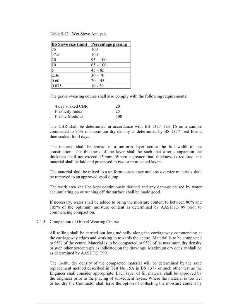
Table 5.12: Wet Sieve Analysis
BS Sieve size (mm) Percentage passing 75 100 37.5 100 20 95 – 100 10 65 – 100 5 45 – 85 2.36 30 – 70 0.60 20 – 45 0.075 10 - 30 The gravel-wearing course shall also comply with the following requirements: • 4 day soaked CBR 20 • Plasticity Index 25 • Plastic Modulus 500 The CBR shall be determined in accordance with BS 1377 Test 16 on a sample compacted to 95% of maximum dry density as determined by BS 1377 Test B and then soaked for 4 days. The material shall be spread in a uniform layer across the full width of the construction. The thickness of the layer shall be such that after compaction the thickness shall not exceed 150mm. Where a greater final thickness is required, the material shall be laid and processed in two or more equal layers. The material shall be mixed to a uniform consistency and any oversize materials shall be removed to an approved spoil dump. The work area shall be kept continuously drained and any damage caused by water accumulating on or running off the surface shall be made good. If necessary, water shall be added to bring the moisture content to between 80% and 105% of the optimum moisture content as determined by AASHTO 99 prior to commencing compaction. 7.1.5 Compaction of Gravel Wearing Course All rolling shall be carried out longitudinally along the carriageway commencing at the carriageway edges and working in towards the centre. Material is to be compacted to 95% of the centre. Material is to be compacted to 95% of its maximum dry density or such other percentages as indicated on the drawings. Maximum dry density shall be as determined by AASHTO T99. The in-situ dry density of the compacted material will be determined by the sand replacement method described in Test No 15A in BS 1377 or such other test as the Engineer shall consider appropriate. Each layer of fill material shall be approved by the Engineer prior to the placing of subsequent layers. Where the material is too wet or too dry the Contractor shall have the option of collecting the moisture content by

watering or drying as appropriate, or modifying his compaction procedure so as to obtain the required dry density. 7.2 Rehabilitation of Existing Access Roads 7.2.1 General The provisions of Clause 2 shall apply save where expressly varied hereunder. All interventions shown on strip maps provided are subject to confirmation by the Engineer on Site. 7.2.2 Site Clearing The width and length over which site clearing is to be carried out shall be as instructed by the Engineer. 7.2.3 Spoil of Unsuitable Material This shall be in situ material, which is unsuitable to remain in the road, and has been instructed by the Engineer to be spoilt. Unsuitable material shall be deposited in spoil areas located by the Contractor subject to the approval by the Engineer. The rate for spoil shall include for the cost of excavating the material, loading, transporting, depositing, spreading and levelling the material in a spoil area, all to the satisfaction of the Engineer. 7.2.4 Earthworks Fill The Contractor shall supply from a source approved by the Engineer, place and compact suitable borrow material having a minimum CBR of 10%, at 95% compaction as determined by AASHTO T99 to areas that require to be raised or where there is a deficiency of in situ material for reshaping. 7.2.5 Light Grading Where this term is instructed, the road shall be graded to redistribute the existing material as required to achieve the specified cross section of the road, watered and compacted. This item applies where the required movement of material is not greater than 1m3/m 7.2.6 Heavy Grading The Contractor shall scarify the road surface, add fill material where required, reshape and compact to achieve the specified cross section. This item applies where the required movement of material is greater than 1m3/m 7.2.7 Gravel Stockpiling No separate measurement shall be made for stockpiling gravel and the Contractor will be deemed to have allowed for the costs elsewhere in his rates.
7.2.8 Overburden Removal The removal of vegetation, topsoil and overburden at gravel borrow pits shall not be paid for separately. Contractor will be deemed to have allowed for the costs elsewhere in his rates. The same applies to any works required to access the borrow pits. 7.2.9 Haulage The rate for gravel wearing course includes for the supply of material inclusive of extraction, loading and transportation to Site for a maximum haulage distance of 30km. Where suitable gravel is not available within this distance, overhaul will be paid for. Measurement shall be the product of the volume of compacted material in situ and the haulage distance in excess of 30km, one way, along the shortest route, as determined by the Engineer. 7.3 Drainage Works 7.3.1 Culvert Installation This shall include the provision and installation of a specified internal diameter including excavation and backfill to a compaction of 95% of maximum dry density as determined by AASHTO T99. The backfill material is to be approved by the Engineer. The rate includes any provisions necessary for diversion of traffic.
7.3.2 Mass Concrete, Beds and Surrounds Unless otherwise shown on the drawings, the concrete shall be class C20/20 7.3.3 Mitre Drains and Catch Water Drains These will be formed at the locations and the lines and levels shown on the drawings or instructed by the Engineer. 7.3.4 Side Drains These will be formed to the lines and levels as shown in the drawings and at locations as instructed by the Engineer. Material excavated from the side drains may be incorporated into the reshaped road if suitable. Otherwise, it shall be spoiled in approved spoil areas. 7.3.5 Cleaning of Existing Drains The Contractor shall clean existing blocked culverts and clear side drains as may be directed by the Engineer. 7.3.6 Repair of Existing Drains The Contractor shall replace broken culverts, and repair or reconstruct broken wingwalls and headwalls as directed by the Engineer.
8. CONSTRUCTION TOLERANCES The following are the tolerances within which the works are to be executed or as directed by the Engineer:
EARTHWORKS Top level of Embankments after compaction +100/ -0mm Sides of Embankments over a 10 m length +100/ -0mm Channel or Excavation cutting +20/ -20mm Channel Water Way Area - 0 Horizontal Alignment of Channels: Maximum 300mm Over 20m length 100 mm Formation Level for Structures +0/ -ve filled with concrete Formation Level for Gabions +0/ -100mm CONCRETE STRUCTURES The following tolerances shall apply to all wrought formed and fair or fine unformed finishes. Tolerance from Specified Position Maximum departure of plan position of structure 150mm Tolerance from Specified Dimension Maximum departure in thickness, cross sectional dimension or position of columns, beams, walls, footings and the like +25/ -10mm Surface Tolerance on Straightness or Departure from Specified Curve General Surfaces Maximum deviation in horizontal or vertical direction • gradual over a 10m length 25mm • abrupt 10mm Surfaces in Contact with Flowing Water Maximum deviation in direction of flow or normal to flow • gradual over a 10m length 15mm
• abrupt 5mm Reinforcement Maximum departure in required spacing 15mm Minimum lap length shall be: • In the case of mild steel reinforcing 40 times bar diameter • in the case of high yield steel reinforcing 50 times bar diameter Stonework Pitching and Masonry over a 2 m length +100/ -25mm Face of gabion basket +75/ -25mm Thickness of tipped rock or filter layer +100/ - 0mm
TECHNICAL SPECIFICATIONS FOR BOREHOLE DRILLING AND EQUIPING 1 BOREHOLE DRILLING 1.1 GENERAL Wherever reference is made in the Contract to specific standards and codes to be met by the goods and materials to be furnished, and work performed or tested, the provisions of the latest current edition or revision of the relevant standards and codes in effect shall apply, unless otherwise expressly stated in the Contract. Where such standards and codes are national, or relate to a particular country or region, other authoritative standards that ensure a substantially equal or higher quality than the standards and codes specified will be accepted subject to the Project Manager’s prior review and written consent. This contract comprises the drilling, construction, development; test pumping, water quality analysis and erection of a gantry. The drill sites are indicated in the zone allocation list. 1.2 REGULATIONS AND STANDARDS The borehole shall be drilled at the site to be identified by the Project Manager. Each borehole shall be drilled to a depth specified in the hydrogeological survey report. It shall be drilled through all strata encountered. The Employer will acquire the relevant permits and Government authorizations. 1.2 MOBILIZATION, DEMOBILIZATION AND RESTITUTION 1.2.1 The Contractor shall mobilize to the site in accordance with the Agreed Program. The sum for mobilization/demobilization shall include transportation of machinery, erection, dismantling and preparation of temporary camps as the Contractor deems necessary, provision of drilling and development fluids (bentonite, foam, water), water for camping, personnel sanitary facilities. 1.2.2 The Contractor shall minimize disturbance to neighboring plots. This shall particularly include ensuring that bailed fines and pumped test water are discharged in a manner that does not create a nuisance either to the public or private property. 1.2.3 Site re-instatement under the conditions of contract shall include the removal of all hydrocarbons spilled, leaked or otherwise released and associated packaging and cotton
waste. Site re-instatement is deemed an integral part of mobilization. This activity shall be costed taking into account the items above and expressed as a lump sum. 1.3. DRILLING 1.3.1 Unless otherwise approved by the Project Manager, drilling shall be by the air hammer method, by flush rotary drilling or by the percussion method. Drilling shall continue through all strata encountered. Drilling fluids and additives used must be approved by the Project Manager prior to use. The Contractor shall provide the appropriate tools and equipment and maintain them in good condition capable of operating to the manufacturer’s rating to ensure a smooth, a smooth, straight hole. 1.3.2 Drilling shall continue to the stipulated total depth at a minimum diameter of 205mm (8 inches) to provide for a finished borehole of a cased internal diameter of 152mm after allowing for 50mm thick gravel pack and temporary casings as found necessary. The Project Coordinator reserves the right to stop drilling operation if he considers that further drilling is unlikely to be advantageous. In this event payment shall only be made for the amount of work actually executed. 1.3.3 All materials used in the borehole construction other than temporary works shall comply with the relevant standard specifications. A tolerance in dimensions will be permitted provided that the material quality is not inferior to specification and work is in no way impaired. 1.3.4 The boreholes shall be drilled straight and vertical. 1.4 SAMPLE COLLECTION, STORAGE AND RECORD KEEPING 1.4.1 Samples of the drill cuttings returned to the surface shall be collected at two (2) meter intervals, dried and bagged. Each bag shall be clearly marked with the sample depth interval and borehole number. The Contractor shall record the depth and any zone of lost circulation for which no sample was taken. 1.4.2 TheContractor shall maintain a log of the penetration rate on a meter by meter basis, in minutes per meter drilled. A stopwatch shall be used for this purpose so that only the net drilling time is recorded, excluding any time taken in drilling disruptions. 1.4.3 The depth of any voids, or of particular rapid penetration, or significant changes in rig noise shall also be noted. 1.4.4 Water level shall be measured and recorded at the start and end of every shift, after significant breaks in activity (such as meal breaks), and during periods of plant downtime (as appropriate). The water levels shall be measured using a sounding and/or lighting dipper approved for use by the Project Manager. 1.5 SUPPLY AND INSTALLATION OF CASINGS AND SCREENS 1.5.1 CASING AND SCREEN SPECIFICATIONS a). Casings shall be new, 152mm (6 inches) internal diameter, black pipe class B, with a minimum wall thickness of 4.0mm in 6 meter lengths.
b). Mill slotted screens shall be constructed from new 152mm internal diameter black pipe class B with a minimum wall thickness of 4.0mm. Slots shall not exceed 1.0 mm in width, and should constitute not less than 6.0% open space area. Gas slotted casing screens are not acceptable. 1.5.2 CASINGS AND SCREEN INSTALLATION a). Before installation of the casings and screens, the Contractor shall ensure that the hole is clear to the total depth and shall flush out any backfilled materials present. The Project Manager shall provide the design of the casings and screens string prior to installation by the Contractor. b). Casing jointing shall be by either flush square-section threading or tree pass electric arc welding. Screens may be welded to casing, or screw-jointed by means of flush square-section threads. Externally socket joints may be welded to the casing, or screw-jointed by means of flush square-section threads. Externally socketed joints will not be accepted. Where screwed joints are deemed by the Project Manager to be below standard, joint shoulders shall be spot welded at 900mm interval around the casing circumference at no extra cost. If screens and casing are to be welded, the appropriate welding electrode must be used. c). During welding, casing and screen lengths must be held absolutely vertical in order to ensure a plumb installation. All joints to be welded must be beveled at the butt end; three continuous weld passes must be made to ensure a sound joint and the oxide coating be removed before the second and third passes. d). Burn-through and subsequent deposition of metal on the inside of the casings and screens must be avoided. The base of the casing shall be sealed, unless otherwise directed by the Project Manager, with a circular plate of black pipe class B of thickness not less than 4.0mm (1/4 inch) fixed with a continuous weld to the casing strip. The appropriate welding electrode shall be used. The weld passes will be made, with oxide coating removed prior to the second and third passes. The top of the casing straight shall terminate not less than 600mm above the highest recorded level of ground at the site. e). The contractor shall be responsible for the provision of temporary casings as necessary, including the insertion and removal. Where the Project Manager deems it necessary to have temporary casings left in the borehole as a measure of securing the borehole, this will be indicated in the item for other works in the bill of quantity. 1.5.3 ADMISSIBLE RATES a). Rates shall be expressed as supply and installation of casing or screen per Unit Linear Meter. 1.6 SUPPLY AND INSTALLATION OF GRAVEL PACK 1.6.1 SPECIFICATIONS a). The Contractor shall supply and install filter pack/formation stabilizer. The material shall be 2-4 mm diameter, clean well rounded riverbed siliceous gravel with no more than 5.0% non-siliceous material. The pack must be approved by the Project Manager prior to
installation. Granular calcium hypochlorite will be introduced into the annular space along the pack material at a concentration of 500 grams per cubic meter of pack. The gravel pack shall be placed in the production boreholes to a thickness of 50mm around the casing upto where all screen zones are covered with the gravel as per the Project Manager’s satisfaction. This will initiate the process of sterilizing the wellbore. The Contractor shall provide the Project Manager with the bulk density of the pack material (Kg/M3). b). Installation of the filter pack/formation stabilizer may be water wash down or reverse circulation methods. In the latter case a pump set or airlift string shall be installed in the bore so as to encourage material settlement. The filter pack shall terminate not less than 3.0 meters above the uppermost screen when stabilized, or as otherwise directed by the Project Manager. The Contractor shall provide a means by which this level shall be measured. 1.6.2 ADMISSIBLE RATES Rates shall be expressed as supply and installation of gravel pack per Unit Cubic Meter. 1.7 INSTALLATION OF BACKFILL 1.7.1 SPECIFICATIONS a). Backfill material shall comprise of fine clayey drill cuttings and shall be installed from the top of the filter pack to 3.0 meters below ground level unless otherwise directed by the Project Manager. The installation method must ensure that no bridging occurs within the annular space. b). The Contractor shall measure the depth to the top of the backfill and provide the means by which this level may be measured. 1.7.2 ADMISSIBLE RATES Rates shall be expressed as installation of backfill per Unit Linear Meter. 1.8 DEVELOPMENT Development shall comprise both Physical and Chemical development, and shall include the following operations: - 1.8.1 BOREHOLE CLEANING a). The Contractor shall clean the borehole to its “completed depth” using any of the methods listed below or as otherwise authorized by the Project Coordinator- • By bailer with percussion drilling rig • By means of airlift, which may use a light or stable foam to assist in the removal of materials from the borehole. • By means of educator airlift, with or without light or stable foam.

b). Bailers and other down hole plant shall adopt diameter limits of half a normal size or smaller (12.5mm or ½ inch) than the smallest casing or screen diameter. c). Water levels shall be measured and recorded at the start and end of every shift, at significant breaks in activity (such as meal breaks), and during periods of plant downtime (as appropriate). Water levels be measured using a sounding and/or lighting dipper previously approved by the Project Manager. d). The borehole shall be deemed clean when measured drilled depth has been reached and when insignificant or no materials is removed from the base of the borehole. Cleaning costs shall be expressed as a rate Per Hour. 1.8.2 CHEMICAL DEVELOPMENT a). When the Project Coordinator has deemed the borehole clean; he may instruct the Contractor to commence with Chemical development. Chemical development shall comprise of an approved Polyphosphate as a disaggregate that shall break down the silty concentrations, any buildup clay or silts, or other fine materials within and adjacent to the borehole. The decision as whether chemical development shall be adopted and what dosage rates shall be made by the Project Manager. b). Typical dosage shall comprise of powdered Sodium Hex metaphosphate dissolve in hot water. The polyphosphate shall be dosed at 10 to 15 Kg/m3 of water depending on the concentration of clays in the aquifer matrix. This shall be mixed with calcium hypochlorite at a dose of 200grammes per cubic meter to inhibit bacteria activity. The volume of polyphosphate dosed water shall be one and a half times the Volume of water within the screen section. c) Both polyphosphate and added water shall be introduced by means of a pipe, the bottom end of that shall be located in the middle of the screen section of the borehole. The Contractor may get the liquids into the screened section using a jetting head if he wishes. d). After dosing, the borehole shall be left overnight to allow disaggregation to occur. The borehole shall then be subject to physical development. e). Chemical development costs shall be expressed as an Hour rate, and include all labour and materials (including clean water) required for the operation. Chemical development undertaken by a Contractor familiar with the technique shall take no longer than three (3) hours. 1.8.3 PHYSICAL DEVELOPMENT a). Physical development may adopt any of the commonly used methods, including but not necessarily restricted to the following: - • Surging • Bailing • High Velocity Water Jetting • Airlift raw hiding • Airlift raw hiding with educator pipe.

b). Development shall be considered complete when the water discharged is clear and contains no more than an estimated 5 parts per millions of suspended solids and the borehole has been restored to the cleaned total depth or as otherwise directed by the Project Manager. c) The Contractor shall describe the method he proposes to adopt and the plant required for physical development in his method statement. Over pumping shall not be considered a development method. The rate submitted by the Contractor for physical development is deemed to include installation and removal of necessary plant. The quantities given in the bills of quantities only apply to actual development time. Costs for physical development shall be expressed as an Hour Rate. 1.9 AQUIFER TESTING Borehole testing will be conducted according to British Standard BS 6316 (1992) (Code of Practice for Test Pumping of Water Wells). The following elements are required.
• A pre-test • A step drawdown test • A constant discharge test • A recovery test
1.9.1 INSTALLATION, PLANT AND METHODOLOGY Pumping plant and dipping tube shall be installed in the borehole to be tested. The Contractor shall investigate and agree with the Project Manager the anticipated discharge and pump intake depth. PUMPING PLANT i. Pumps used for test pumping may electrical submersible or surface-mounted turbine pumps or reciprocating pumps. ii. Any pump used in tests must have a fully functioning non-return valve either in the pump itself or in the rising main immediately above the top of the pump. iii. The Contractor must have pumps covering the anticipated discharge range. iv. The water pumped from the borehole shall be discharged to waste at a distance and in such a manner that it does not pond or flow back towards the borehole. v. The Contractor must provide a generator or other prime mover for powering the pump, as power is not necessarily available at the sites. DISCHARGE MEASUREMENT AND CONTROL Discharge measurements shall be by an approved accurate method, such as an Orifice Plate, calibrated flow meter or a V-notch weir. If volumetric methods are proposed, the Contractor will ensure the container to be used has been calibrated. When time to fill measurements is made, each discharge measurement shall be calculated from the average of three time measurements. Discharge shall vary by no more than 15%across each step of step drawdown test, and across the constant discharge test. WATER LEVEL MEASUREMENT

Water level measurements shall be by electric sounding and/or lighting dipper, and shall be made in a dipper tube installed alongside the test pump rising main and tied securely to it. The Project Manager will check the dipper for stretch and any other inaccuracies prior to accepting its use. Accuracy measurements must not be less than 1.0 cm. Water level measurements using an airline will not be acceptable on the grounds of poor precision. TIME MEASUREMENT All times shall be measured by means of a stopwatch. The Contractor shall ensure that spare batteries etc. for all equipment are available prior to commencing tests. i) PRE-TEST The pre-test will check all equipment, determine the range of discharge for the step drawdown test and set the globe values for the first step discharge rate. Pre-test shall not exceed three (3). ii) STEP DRAWDOWN TEST
• The step drawdown test will comprise five (5) steps tests of sixty (60) minutes each, with no recovery phase between successive steps. The step drawdown test shall not start until water level has returned to the true static water level, unless otherwise directed by the Project Manager. • Typically, individual step discharges would comprise 25%, 50%, 75%, 100% and 125% of the anticipated production discharge rate. • Discharge increments shall be effected as nearly instantaneously as possible and once set shall not be changed except by instruction of the Project Manager. • Discharge variations and measurement shall be effected by means of the globe valve and manometer gauge as follows; A globe valve of suitable diameter shall control the discharge and on the upstream side of this, not closer than six (6) pipe diameters from the valve, a manometer tapping and gauge will be installed such that it can be clearly seen by any person using the valve. This will be used during the step drawdown tests for the flow control purposes. iii) CONSTANT DISCHARGE TEST Constant discharge test shall typically last not less than twenty-four (24) hours, or as otherwise determined by the Project Manager. A water sample will be procured towards the end of the test for subsequent analysis by a competent laboratory. iv) RECOVERY TEST AND REMOVAL OF PLANT Recovery tests shall not continue for more than twenty-four (24) hours, or as otherwise directed by the Project Manager. Only after the completion of recovery data collection may pumping and ancillary plant be removed from the borehole, though above ground components may be dismantled during the recovering phase. v) ADMISSIBLE RATES

Rates of pumping and recovery are deemed to include the cost of plant installation and removal. The rates are deemed inclusive of installation, removal, plant use, testing and data collection. 1.10 WATER SAMPLING AND ANALYSIS • In the closing hour of the constant discharge test a water sample shall be collected for chemical and bacteriological analysis by a competent laboratory. The water samples shall be collected in containers supplied by the laboratory, in the manner conventionally used by the laboratory. • The Contractor’s unit rate of sampling and analysis will include the cost of analysis and transportation to and from the laboratory for the sampling exercise. 1.11 BOREHOLE DISINFECTION After removal of test equipment, the borehole shall be disinfected with Chlorine/water solution at a concentration of 50 milligrams per liter or greater of free chlorine. This will be sprayed into the borehole so as to ensure that all exposed borehole wall surfaces are coated. In preparing their Tenders, Contractors should allow for one (1) cubic meter of solution for the borehole. This item shall be costed as a unit Lump Sum 1.12 BOREHOLE HEAD WORKS a) SANITARY SEAL CASING A sanitary seal shall be constructed at the wellhead. This shall comprise the following elements: • A 3.2-meterlength of internal diameter 205 mm (8 inch) plain black pipe class B sanitary steel casing installed around the permanent casing string. • A grout seal between the 254mm sanitary seal casing and the 152 mm permanent casing string. • A 1.0x1.0x1.0 meter reinforced concrete block (Y8/1:2:4) cast around the Sanitary seal casings. • A lockable steel cap. b). GROUT SEAL A sanitary ground seal shall be installed between the 152 mm (6 inch) and 205 mm (8 inch) casings and grouted into place. Grout shall be a cement slurry, or cement and fine sand and shall have a density of at least 1175 Kg/lt.This shall be introduced into the annular space from the top of the inert backfill to the ground level, using a method that must be approved by the Project Manager. c) CONCRETE PLINTH The ground surface at the wellhead shall be excavated to a depth of one (1) meter, and be one meter square, to allow s Concrete Plinth to be cast. The 1.0x1.0x1.0-meter pit will be filled with concrete, to be finished flush with the ground surface. Concrete shall be 1:2:4 OPC:
sand: half-inch ballast. This must be cast with two 0.8 meter lengths of 12 mm reinforcing steel bar welded to the 205 mm (8 inch) casing, 0.7 meter below ground level. d). TEMPORARY CAP The top of the borehole shall be sealed with a cap that shall comprise a round plate of mild steel, of thickness not less than 3.0mm. This will be continuously welded in single pass to the mild steel borehole casing or should be lockable. 1.13 RECORDS After completion of all works at the borehole, the Contractor shall submit to the Project Manager within four (4) days a complete document with the following additions: - • Drilling penetration Log • Geological Log • WAB 28 Borehole Completion Record (Three Complete Sets of Completion Reports shall be submitted.
1.14 TECHNICAL LITERATURE a) A Tenderer must submit the following information together with the Tender documents to assist in fair evaluation: - -Technical specifications on drilling rig and other ancillary equipment (make, model, rated capacity etc.) -Particulars and specifications of materials used in the construction of the borehole. Any other information the tenderer may deem is important in evaluation as well as boosting his/her chances of winning the tender
ELECTRO – MECHANICAL WORKS SPECIFICATIONS 1. ELECTRICAL WORKS 1.1. REGULATIONS AND STANDARDS The complete electrical installation shall be carried out by a competent Contractor and in accordance with the specifications and compliance with the following; (a). Kenya Bureau of Standards (b). Regulations for the Electrical Equipment of Buildings (Latest Edition) issued by the Institution of Electrical Engineers of Great Britain. (c). IEC standards and Electric Power Act and the Rules made there under. (e). Kenya Power & Lighting Co. Ltd Regulations and Bye-Laws. (f). Government Electric Specifications GES 1 and 2 which can be viewed at the office of the Chief Electrical Engineer, Ministry of Roads, Public Works and Housing. (g). Industrial Safety Regulations currently in force. SWITCH GEAR, STARTER PANELS ANDOTHER ENCLOSURES Unless otherwise specified, all shall be surface mounting, water tight, corrosion resistant, vermin-proof, termite-proof, dust-proof and resistant to attack by oils and grease. They shall be fabricated from heavy gauge 16 swg, folded, spangled, galvanized and rust protected sheet steel of minimum thickness 1.5mm. They shall be finished in a two tone, heat resistant, non-peeling-off staved gray enamel paint or epoxy powder coating. 1.2. ELECTRIC CABLES Unless otherwise specified, all cables shall be made of copper material and conform to BSS 6004, 600/1000 volts’ grade. (i). UNARMOURED CABLES:They shall be pvc insulated. (ii). ARMOURED CABLES: They shall be PVC SWA PVC copper cables. (iii). BOREHOLE CABLES They shall be made from tough flexible rubber material that will not allow water to seep through when submerged in the borehole water. 1.2 GS CABLE TRUNKING The trunking shall be manufactured from heavy duty hot dip galvanized mild steel sheet of minimum thickness 1.25 mm with screw-in and twist-to lock top lid. 1.3 PUMP SET STARTER It shall be 3 phase, 415 vacvac, 50/60 Hz Direct-On line. It shall be in a water tight, front access, hinged door, lockable enclosure, comprising of the following components among others fully wired and labeled. The starter shall be fully wired and 3 No. sets of schematic and control wiring drawings MUSTbe supplied along with the starter. - Appropriate rating contactors / appropriate rating thermal overload. - push buttons (green marked “START”, black marked “STOP/RESET”). - Integral TPN (MCB) type 2. - 1 No. 50x50mm AC ammeter of appropriate range. - 1 No. 50x50mm AC voltmeter of range 0-500 vac.c/w protection mcb/fuse. - Over/Under voltage and phase failure protection relay set at 380 and 440 vac. - 2 No.Water level control relays.
- Pilot indicator lights (green marked “PUMP RUN”, red marked “OVER LOAD TRIPPED”, yellow marked ‘BOREHOLE LOW’, etc………. - Hours run counter range 0-99999 hours. Cable terminal blocks of appropriate rating. 1.4 BOREHOLE MOTOR (AS GRUNDFOS) The motor shall be the two pole canned asynchronous, 3 phase, 415 vac, squirrel cage, induction type, continuously rated and of minimum CLASS “B’’ insulation. The entire body including the shaft shall be made of heavy duty stainless steel material. The motor shall be supplied complete with 3 lead copper tail cable. 1.4 BOREHOLE PUMP (AS GRUNDFOS) The pumps shall be the high pressure, vertical mounting, multi-stage, centrifugal type running at a full load speed of not less than 2800 rpm. The entire pump body including the strainer, cable guard, non- return valve, impellers, shaft, locking nuts and washers shall be made of heavy duty stainless steel material. The bearings shall be the water lubricated type, wear resistant. The impeller(s) shall be hydraulically and dynamically balanced. 1.5 WATER LEVEL CONTROL ELECTRODES All the electrodes shall be made of stainless steel material AISI 304 as Omron F03-01, Londex, Ascoor similar approved quality made of stainless steel. The borehole electrodes shall be of size 6.0 mm diameter and 120mm length (D6x120mm) and in their tough moulded shrouds. 1.9 BOREHOLE COMBINED PIPE AND CASING CLAMP The clamp shall be the heavy duty type. It shall comprise of 3 pieces; the bottom half clamps to the borehole casing, while the top portion which rests on the top of the casing clamps to the pipe column and holds it centrally in the casing bore. 1.10 BOREHOLE SUNDRIES Unless otherwise specified, the words “BOREHOLE SUNDRIES” shall mean the following items to be used in the installation, support and inter-connection of the borehole pump and drop pipes to the rising mains. Unless otherwise specified, the GI fittings shall be of the same diameter as the drop pipes. - rolls of 6 water proof adhesive rubber tape and cable ties. - Tee, sockets, nipples, 90o slow bends and plug. - 2 Liters of Boss black type COLAS RC. 1.11RC CABLE AND PIPE ROUTE MARKERS They shall be of size 1100mmLx200mmWx80mmT with the words “POWER CABLE ”OR “WATER PIPE” in 40mm height letters mould cast in black indelible color in the concrete. They shall be caste using Y8 RC concrete of mix ratio (mix ratio 1:3:6). 1.11 HATARI TILES The tiles shall be used to cover the underground armoured cables for protection against mechanical damage. They shall be of size 300mmLx150mmWx30mmT with the word
“HATARI” in 40mm height letters mould cast in the concrete. They shall be pre-cast using concrete of mix ratio (mix ratio 1:3:6). 1.12 GS BOREHOLE PROTECTION COVER The cover shall be all weather-proof, rectangular in shape with pitched top (3o).The cover shall be fabricated from hot dip galvanized heavy gauge (16 swg) sheet steel plate of minimum thickness 1.75mm.It shall have GS solid handles and pad locking facilities on the opposite sides. The cover shall be in an L-SHAPED steel frame (25x25x2.5mm thick). 1.15WIRING METHODS OF ELECTRICAL INSTALLATIONS AT MEDIUM AND LOW VOLTAGEE (i).SYSTEM “A” Plastic insulated cables enclosed in screwed steel conduit or trunking on the surface of walls and ceilings or in the roof space. (ii). SYSTEM “B” Plastic insulated wires armoured cables laid on the surface of walls, cable trays, in cable trenches or ducts. (iii). SYSTEM “C” Plastic insulated cables clipped to the roof members and run in metal or plastic conduit drops concealed in walls or ducts formed in the fabric of the building. 1.18 SYSTEM BONDING All non-conducting metallic parts which form part of the electrical system or are within the vicinity/route of the electrical system shall be effectively bonded to the main earthing system. 1.19 EARTHING SYSTEM All the electrical installation earthing conductors shall be connected to the earth electrode through an earth lead. The earth lead shall be firmly connected to the electrode by means of the clamp, after which a thin film of grease or Vaseline shall be applied at the clamp area for protection against corrosion.

SECTION VII – BILLS OF QUANTITIES
A. Preamble 1. The Bill of Quantities shall be read in conjunction with the Instructions to Tenderers, General and Special Conditions of Contract, Technical Specifications, and Drawings. 2. The quantities given in the Bill of Quantities are estimated and provisional, and are given to provide a common basis for bidding. The basis of payment will be the actual quantities of work ordered and carried out, as measured by the Contractor and verified by the Engineer and valued at the rates and prices bid in the priced Bill of Quantities, where applicable, and otherwise at such rates and prices as the Engineer may fix within the terms of the Contract. 3. The rates and prices bid in the priced Bill of Quantities shall, except insofar as it is otherwise provided under the Contract, include all Constructional Plant, labour, supervision, materials, erection, maintenance, insurance, profit, taxes, and duties, together with all general risks, liabilities, and obligations set out or implied in the Contract. 4. A rate or price shall be entered against each item in the priced Bill of Quantities, whether quantities are stated or not. The cost of Items against which the Contractor has failed to enter a rate or price shall be deemed to be covered by other rates and prices entered in the Bill of Quantities. 5. The whole cost of complying with the provisions of the Contract shall be included in the Items provided in the priced Bill of Quantities, and where no Items are provided, the cost shall be deemed to be distributed among the rates and prices entered for the related Items of Work. 6. General directions and descriptions of work and materials are not necessarily repeated nor summarized in the Bill of Quantities. References to the relevant sections of the Contract documentation shall be made before entering prices against each item in the priced Bill of Quantities. 7. Provisional Sums included and so designated in the Bill of Quantities shall be expended in whole or in part at the direction and discretion of the Employer in accordance with Clauses 58.4 of the SCC. 8. The method of measurement of completed work for payment shall be in accordance with clauses 56.1 and 57.1 of the SCC.

9. Errors will be corrected by the Employer for any arithmetic errors in computation or s summation as follows: (a) where there is a discrepancy between amounts in figures and in words, the amount in words will govern; and (b) where there is a discrepancy between the unit rate and the total amount derived from the multiplication of the unit price and the quantity, the unit rate as quoted will govern, unless in the opinion of the Employer, there is an obviously gross misplacement of the decimal point in the unit price, in which event the total amount as quoted will govern and the unit rate will be corrected. 10. Rock is defined as all materials that, in the opinion of the Engineer, require blasting, or the use of metal wedges and sledgehammers, or the use of compressed air drilling for their removal, and that cannot be extracted by ripping with a tractor of at least 150 brake hp with a single, rear-mounted, heavy-duty ripper.
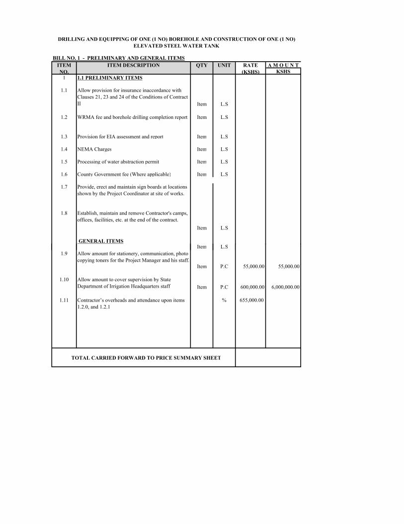
A M O U N TKSHS1 1.1 PRELIMINARY ITEMS1.1 Allow provision for insurance inaccordance with Clauses 21, 23 and 24 of the Conditions of Contract II Item L.S1.2 WRMA fee and borehole drilling completion report Item L.S1.3 Provision for EIA assessment and report Item L.S1.4 NEMA Charges Item L.S1.5 Processing of water abstraction permit Item L.S1.6 County Government fee (Where applicable) Item L.S1.7 Provide, erect and maintain sign boards at locations shown by the Project Coordinator at site of works.1.8 Establish, maintain and remove Contractor's camps, offices, facilities, etc. at the end of the contract. Item L.S
GENERAL ITEMS Item L.SDRILLING AND EQUIPPING OF ONE (1 NO) BOREHOLE AND CONSTRUCTION OF ONE (1 NO) ELEVATED STEEL WATER TANK
BILL NO. 1 - PRELIMINARY AND GENERAL ITEMSITEM NO.
ITEM DESCRIPTION QTY UNIT RATE (KSHS)Item L.S1.9 Allow amount for stationery, communication, photo copying toners for the Project Manager and his staff. Item P.C 55,000.00 55,000.00 1.10 Allow amount to cover supervision by State Department of Irrigation Headquarters staff Item P.C 600,000.00 6,000,000.00 1.11 Contractor’s overheads and attendance upon items 1.2.0, and 1.2.1 % 655,000.00
TOTAL CARRIED FORWARD TO PRICE SUMMARY SHEET
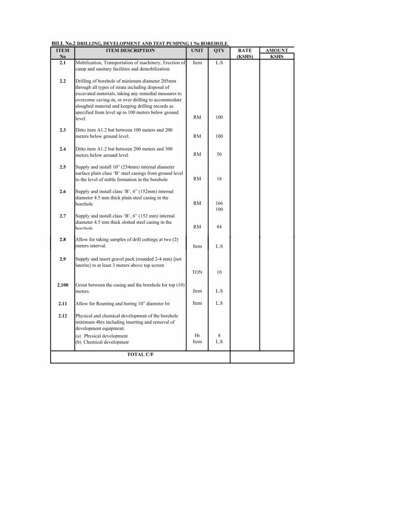
ITEM RATE AMOUNTNo (KSHS) KSHS2.1 Mobilization, Transportation of machinery, Erection of camp and sanitary facilities and demobilization. Item L.S2.2 Drilling of borehole of minimum diameter 205mm through all types of strata including disposal of excavated materials, taking any remedial measures to overcome caving-in, or over drilling to accommodate sloughed material and keeping drilling records as specified from level up to 100 meters below ground level. RM 1002.3 Ditto item A1.2 but between 100 meters and 200 meters below ground level. RM 1002.4 Ditto item A1.2 but between 200 meters and 300 meters below ground level. RM 502.5 Supply and install 10” (254mm) internal diameter surface plain class ‘B’ steel casings from ground level to the level of stable formation in the borehole. RM 182.6 Supply and install class ‘B’, 6” (152mm) internal diameter 4.5 mm thick plain steel casing in the borehole RM 1661002.7 Supply and install class ‘B’, 6” (152 mm) internal diameter 4.5 mm thick slotted steel casing in the borehole RM 842.8 Allow for taking samples of drill cuttings at two (2) BILL No.2 DRILLING, DEVELOPMENT AND TEST PUMPING 1 No BOREHOLE
ITEM DESCRIPTION UNIT QTY
2.8 Allow for taking samples of drill cuttings at two (2) meters interval. Item L.S2.9 Supply and insert gravel pack (rounded 2-4 mm) [not laterite] to at least 3 meters above top screen TON 10
2.100 Grout between the casing and the borehole for top (10) meters. Item L.S2.11 Allow for Reaming and boring 10” diameter bit Item L.S2.12 Physical and chemical development of the borehole minimum 4hrs including inserting and removal of development equipment;(a) Physical development Hr 8(b) Chemical development Item L.S
TOTAL C/F
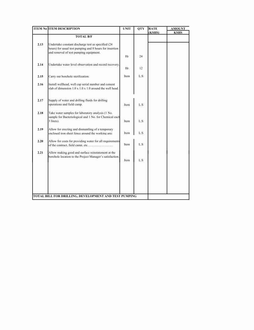
RATE AMOUNT(KSHS) KSHS
TOTAL B/F
2.13 Undertake constant discharge test as specified (24 hours) for usual test pumping and 8 hours for insertion and removal of test pumping equipment. Hr 242.14 Undertake water level observation and record recovery. Hr 122.15 Carry out borehole sterilization. Item L.S2.16 Install wellhead, well cap serial number and cement slab of dimension 1.0 x 1.0 x 1.0 around the well head.2.17 Supply of water and drilling fluids for drilling operations and field camp. Item L.S2.18 Take water samples for laboratory analysis (1 No. sample for Bacteriological and 1 No. for Chemical each 3 liters). Item L.S2.19 Allow for erecting and dismantling of a temporary enclosed iron sheet fence around the working area Item L.S2.20 Allow for costs for providing water for all requirements of the contract, field camp, etc…………………… Item L.S2.21 Allow making good and surface reinstatement at the ITEM No ITEM DESCRIPTION UNIT QTY
2.21 Allow making good and surface reinstatement at the borehole location to the Project Manager’s satisfaction. Item L.STOTAL BILL FOR DRILLING, DEVELOPMENT AND TEST PUMPING
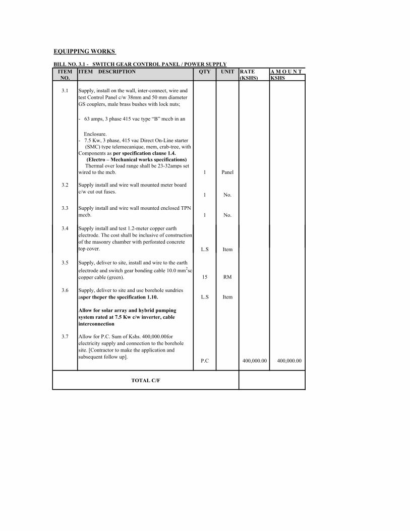
ITEM RATE A M O U N TNO. (KSHS) KSHS3.1 Supply, install on the wall, inter-connect, wire and test Control Panel c/w 38mm and 50 mm diameter GS couplers, male brass bushes with lock nuts;- 63 amps, 3 phase 415 vac type “B” mccb in an Enclosure.- 7.5 Kw, 3 phase, 415 vac Direct On-Line starter (SMC) type telemecanique, mem, crab-tree, withComponents as per specification clause 1.4.
(Electro – Mechanical works specifications) Thermal over load range shall be 23-32amps set wired to the mcb. 1 Panel3.2 Supply install and wire wall mounted meter board c/w cut out fuses. 1 No.3.3 Supply install and wire wall mounted enclosed TPN mccb. 1 No.3.4 Supply install and test 1.2-meter copper earth electrode. The cost shall be inclusive of construction of the masonry chamber with perforated concrete top cover. L.S ItemBILL NO. 3.1 - SWITCH GEAR CONTROL PANEL / POWER SUPPLY
EQUIPPING WORKS
ITEM DESCRIPTION QTY UNITtop cover. L.S Item3.5 Supply, deliver to site, install and wire to the earth electrode and switch gear bonding cable 10.0 mm2sc copper cable (green). 15 RM3.6 Supply, deliver to site and use borehole sundries asper theper the specification 1.10. L.S ItemAllow for solar array and hybrid pumping system rated at 7.5 Kw c/w inverter, cable interconnection 3.7 Allow for P.C. Sum of Kshs. 400,000.00for electricity supply and connection to the borehole site. [Contractor to make the application and subsequent follow up]. P.C 400,000.00 400,000.00
TOTAL C/F
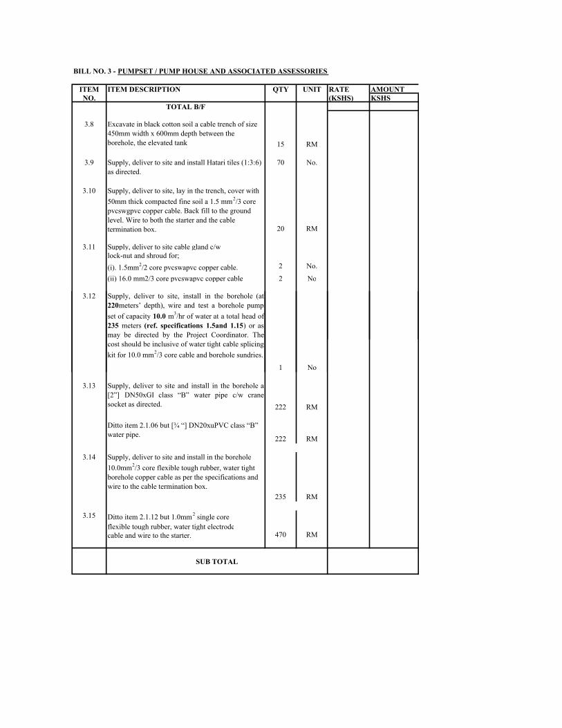
ITEM RATE AMOUNTNO. (KSHS) KSHS
TOTAL B/F3.8 Excavate in black cotton soil a cable trench of size 450mm width x 600mm depth between the borehole, the elevated tank 15 RM3.9 Supply, deliver to site and install Hatari tiles (1:3:6) as directed. 70 No.3.10 Supply, deliver to site, lay in the trench, cover with 50mm thick compacted fine soil a 1.5 mm2/3 core pvcswgpvc copper cable. Back fill to the ground level. Wire to both the starter and the cable termination box. 20 RM3.11 Supply, deliver to site cable gland c/wlock-nut and shroud for;(i). 1.5mm2/2 core pvcswapvc copper cable. 2 No.(ii) 16.0 mm2/3 core pvcswapvc copper cable 2 No3.12 Supply, deliver to site, install in the borehole (at220meters’ depth), wire and test a borehole pumpset of capacity 10.0 m3/hr of water at a total head of235 meters (ref. specifications 1.5and 1.15) or asmay be directed by the Project Coordinator. Thecost should be inclusive of water tight cable splicingBILL NO. 3 - PUMPSET / PUMP HOUSE AND ASSOCIATED ASSESSORIES
ITEM DESCRIPTION QTY UNITcost should be inclusive of water tight cable splicingkit for 10.0 mm2/3 core cable and borehole sundries. 1 No3.13 Supply, deliver to site and install in the borehole a[2”] DN50xGI class “B” water pipe c/w cranesocket as directed. 222 RMDitto item 2.1.06 but [¾ “] DN20xuPVC class “B” water pipe. 222 RM3.14 Supply, deliver to site and install in the borehole 10.0mm2/3 core flexible tough rubber, water tight borehole copper cable as per the specifications and wire to the cable termination box. 235 RM3.15 Ditto item 2.1.12 but 1.0mm2 single coreflexible tough rubber, water tight electrodecable and wire to the starter. 470 RMSUB TOTAL
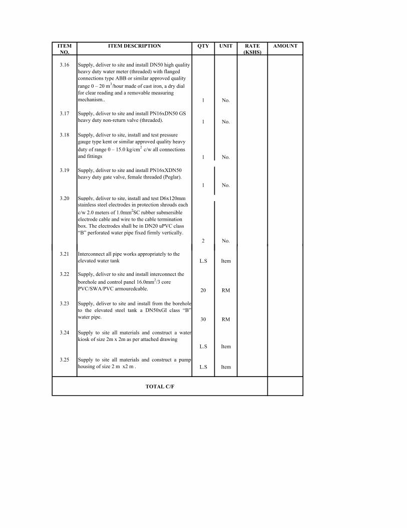
ITEM RATE AMOUNTNO. (KSHS)3.16 Supply, deliver to site and install DN50 high quality heavy duty water meter (threaded) with flanged connections type ABB or similar approved quality range 0 – 20 m3/hour made of cast iron, a dry dial for clear reading and a removable measuring mechanism.. 1 No.3.17 Supply, deliver to site and install PN16xDN50 GS heavy duty non-return valve (threaded). 1 No.3.18 Supply, deliver to site, install and test pressure gauge type kent or similar approved quality heavy duty of range 0 – 15.0 kg/cm2 c/w all connections and fittings 1 No.3.19 Supply, deliver to site and install PN16xXDN50 heavy duty gate valve, female threaded (Peglar). 1 No.3.20 Supply, deliver to site, install and test D6x120mmstainless steel electrodes in protection shrouds each c/w 2.0 meters of 1.0mm2SC rubber submersible electrode cable and wire to the cable termination box. The electrodes shall be in DN20 uPVC class “B” perforated water pipe fixed firmly vertically. 2 No.ITEM DESCRIPTION QTY UNIT3.21 Interconnect all pipe works appropriately to the elevated water tank L.S Item3.22 Supply, deliver to site and install interconnect the borehole and control panel 16.0mm2/3 core PVC/SWA/PVC armouredcable. 20 RM3.23 Supply, deliver to site and install from the boreholeto the elevated steel tank a DN50xGI class “B”water pipe. 30 RM3.24 Supply to site all materials and construct a waterkiosk of size 2m x 2m as per attached drawing L.S Item3.25 Supply to site all materials and construct a pumphousing of size 2 m x2 m . L.S Item
TOTAL C/F

PROTECTION CHAMBERS,
ITEM RATE AMOUNTNO. (KSHS) KSHS
TOTAL B/F3.26 Excavate foundation trench of size 1.5MLx1.5MWx 1.0M depth (1.5-meter square hole) in normal soil and compact the floor. L.S ItemSupply, deliver to site and place concrete (1:3:6) ofthickness 250mm in the trench. L.S Item2.2.02 Supply, deliver to site dressed building stones of size 375x225x150mm and erect a course of a wall around the borehole to 750mm below the ground level such that the internal dimensions of the chamber is 1200mm square and be level with the parking area road level. L.S ItemHard compact the fine soil inside the hole to a depth of 900mm below the ground level, fill in the whole 150-250 mm stone boulders and compact hard. And place 50mm thick compacted concrete blinder (1:6:9) and place 200mm thick 1:3:6 floor slab concrete to 100mm below the ground level. L.S ItemSupply, deliver materials to site, plaster the inside ofthe chamber and finish the top with nilo. 1.25 m3ITEM DESCRIPTION QTY UNITSupply, deliver to site and install lockable2 flap lockable, water tight chequered steel top lid of dimensions 1200x1200x2.0 mm thickness to fit borehole protection chamber. It shall be in a GS frame c/w heavy duty stainless steel padlock L.S Item22.04 Supply, deliver to site and install RC cable routemarker as per the specification 1.11 and of size1100x200x80mm thick. Use 0.13 M3 concrete(1:3:6) to install each marker. The cost should beinclusive of concrete and excavation of a squarehole of size 450x450x600mm depth hole. 2 No.TOTAL SUMMARY PAGE
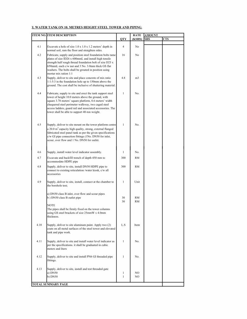
CAPACITY FABRICATED ELEVATED STEEL WATER TANK ON 10. METRES HEIGHT STEEL TOWER AND PIPING.
RATEQTY (KSHS) SHS CTS4.1 Excavate a hole of size 1.0 x 1.0 x 1.2 meters’ depth in normal soil, ram the floor and straighten sides. 4 No4.2 Fabricate, supply and position steel foundation bolts tame plates of size ID26 x 600mmL and install high tensile strength half rough thread foundation bolt of size D25 x 650mmL each c/w nut and 3 No. 3.0mm thick GS flat washers. The bolts shall be grouted in position using mortar mix ration 1:1 16 No4.3 Supply, deliver to site and place concrete of mix ratio 1:1:5:3 in the foundation hole up to 150mm above the ground. The cost shall be inclusive of shuttering material. 4.8 m34.4 Fabricate, supply to site and erect the tank support steel tower of height 10.0 meters above the ground, with square 3.78 meters’ square platform, 0.6 meters’ width chequered steel perimeter walkway, two caged steel access ladders, guard rail and associated accessories. The tower shall be able to support 40-ton weight. 1 No.4.5 Supply, deliver to site mount on the tower platform centre a 20.0 m3 capacity high quality, strong, external flanged fabricated steel panel tank as per the given specifications c/w GI pipe connection fittings (1No. DN50 for inlet, scour, over flow and 1 No. DN50 for outlet. 1 No.ITEM NO. ITEM DESCRIPTION AMOUNT4.6 Supply, install water level indicator assembly. 1 No.4.7 Excavate and backfill trench of depth 450 mm to accommodate HDPE pipe 300 RM4.8 Supply, deliver to site, install DN50 HDPE pipe to connect to existing reticulation /water kiosk, c/w all accessories 300 RM4.9 Supply, deliver to site, install, connect at the chamber to the borehole test; 1 Unit a) DN50 class B inlet, over flow and scour pipesb ) DN50 class B outlet pipe 30 RM30 RMNOTEThe pipes shall be firmly fixed on the tower columns using GS steel brackets of size 25mmW x 4.0mm thickness.4.10 Supply, deliver to site aluminum paint. Apply two (2) coats on all metal surfaces of the steel tower and elevated tank and pipe work. L.S Item4.11 Supply, deliver to site and install water level indicator as per the specifications. it shall be graduated in cubic meters and liters 1 No.4.12 Supply, deliver to site and install PN6 GI threaded pipe fittings. 1 No.4.13 Supply, deliver to site, install and test threaded gate a) DN50 1 NOb) DN50 1 NO
TOTAL SUMMARY PAGE
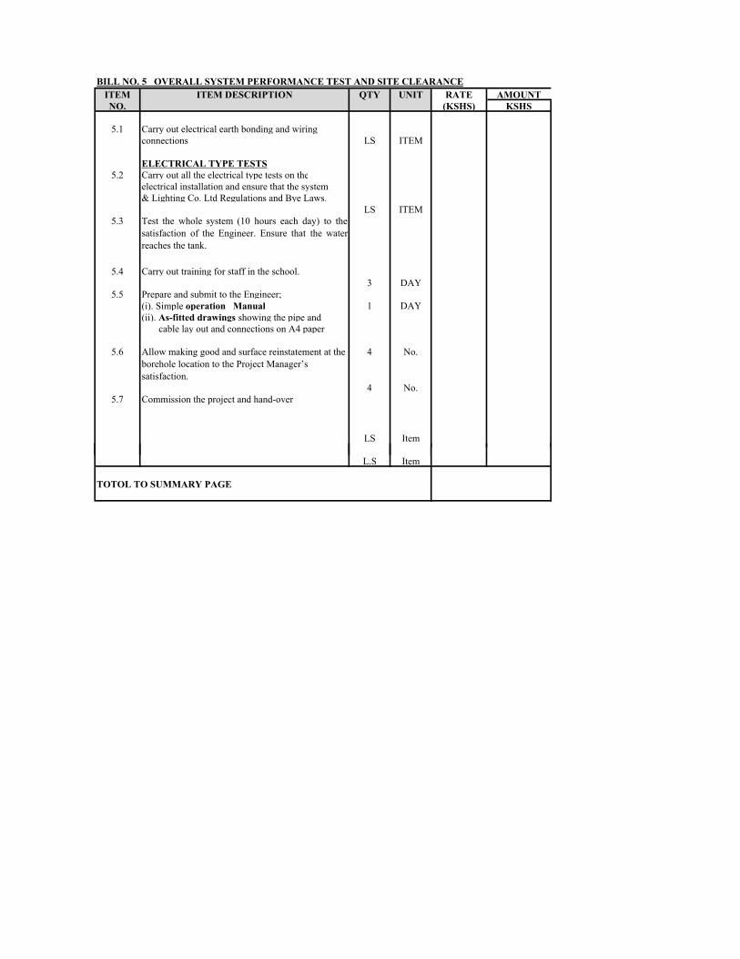
ITEM RATE AMOUNTNO. (KSHS) KSHS5.1 Carry out electrical earth bonding and wiring connections LS ITEM
ELECTRICAL TYPE TESTS5.2 Carry out all the electrical type tests on theelectrical installation and ensure that the system & Lighting Co. Ltd Regulations and Bye Laws. LS ITEM5.3 Test the whole system (10 hours each day) to thesatisfaction of the Engineer. Ensure that the waterreaches the tank.5.4 Carry out training for staff in the school. 3 DAY5.5 Prepare and submit to the Engineer;(i). Simple operation Manual 1 DAY(ii). As-fitted drawings showing the pipe and cable lay out and connections on A4 paper5.6 Allow making good and surface reinstatement at the borehole location to the Project Manager’s satisfaction. 4 No.4 No.5.7 Commission the project and hand-over LS ItemITEM DESCRIPTION QTY UNITBILL NO. 5 OVERALL SYSTEM PERFORMANCE TEST AND SITE CLEARANCEL.S ItemTOTOL TO SUMMARY PAGE

1 Leveling of greenhouse area1.1 Leveling and preparing of a greenhouse area for construction works (about 150 m2 for one greenhouse) m2 150.01.2 Excavation of foundation pits diameter not less than 0.25m and depth 0.75m (26 points for one greenhouse) m3 3.001.3 Allow for back filling of pits. m3 1.081.4 Leveling works of waste soil m3 1.922 Construction of greenhouse Provide all material and construct green house2.1 Gravel layer (H = 10 cm) m3 0.422.2 Concreting of monolithic foundation m3 1.502.3 Metal structure of greenhouse; round-section steel pipe D = 48x2 mm kg 263.672.4 Metal structure of greenhouse; round-section steel pipe D = 40x2 mm kg 6.062.5 Metal structure of greenhouse; square-section steel pipe 30x30x2 mm kg 449.912.6 Metal structure of greenhouse; metal strip for doors and windows 20x3mm kg 14.572.7 Hinges for doors and windows set 16.02.8 Double oil painting of the metal structure set 1.02.9 Purchase and installation of five layer greenhouse polyethylene film; 2 x 200 m2 (from Israel or m2 400.0BILL NO. 6 CONSTRUCTION OF GREEN HOUSE DIMENSION; LENGTH-16m, WIDTH-8m, AREA- 128m2
Item Description of works Unit Quantity Rate (Kshs.) Amount (Kshs.)polyethylene film; 2 x 200 m2 (from Israel or 2.10 Covering of greenhouse façade by polycarbonate sheet with 4 mm thick. m2 180.02.11 All the necessary galvanized profiles for fixing of polyethylene film and polikarbonate sheets, galvanized screws and springs set 1.02.12 Metal ropes along the greenhouse (10pcs; thickness 4 mm ) m 160.02.13 Metal hangers with kaprone rope for plants pcs 300.0
3 Pipework3.1 Allow for Kshs.75,000.00 for pipework to be expended on instruction by the Engineer. 75,000.00 TOTAL TO SUMMARY PAGE

ITEM DESCRIPTION1 TOTAL BILL No. 1 (PRELIMINARY AND GENERAL ITEMS)2 TOTAL BILL No.2(DRILLING, DEVELOPMENT AND TEST 3 TOTAL BILL No. 3 (EQUIPPING & CONVEYANCE)4 TOTAL BILL No. 4 (WATER TANK & CONVEYANCE)5 TOTAL BILL No. 5(OVERALL SYSTEM PERFORMANCE TEST 6 TOTAL BILL No. 6(GREEN HOUSE)
SUB-TOTAL
ADD 10% CONTINGECIES
GRAND TOTAL
BILLS OF QUANTITIES PRICE SUMMARY SHEET
A M O U N T (KSHS)

SECTION VIII – DRAWINGS
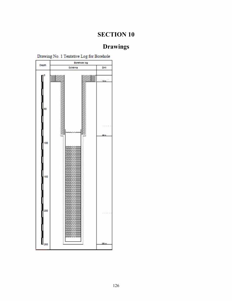
126 SECTION 10
Drawings
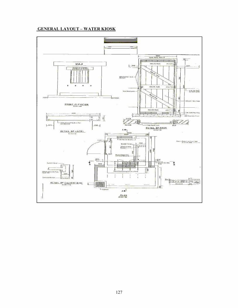
127 GENERAL LAYOUT – WATER KIOSK
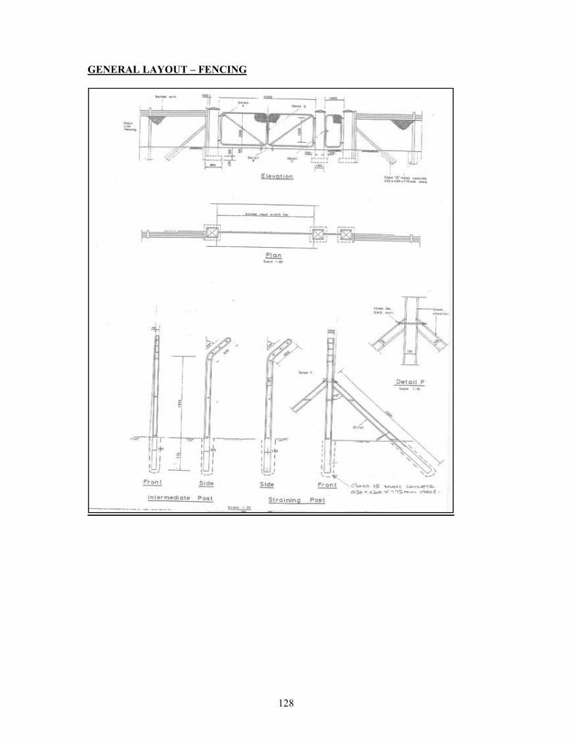
128 GENERAL LAYOUT – FENCING
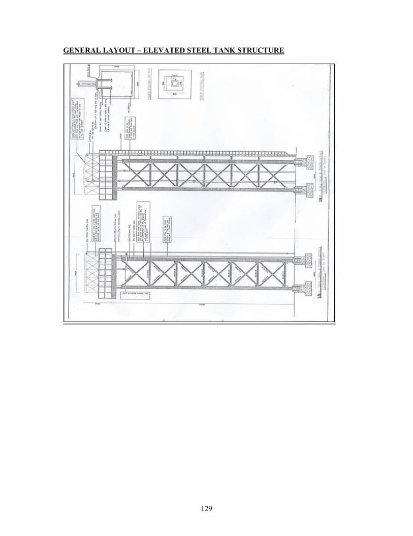
129 GENERAL LAYOUT – ELEVATED STEEL TANK STRUCTURE

SECTION VIII – STANDARD FORMS 1. Form of Tender 2. Appendix to Form of Tender 3. Letter of Acceptance 4. Form of Agreement 5. Tender Securing Declaration Form 6. Performance Bank Guarantee(unconditional) 7. Bank Guarantee for Advance Payment 8. Tender Questionnaire 9. Confidential Business Questionnaire 10. Schedule of Materials;- Basic Prices 11. Schedule of Labour;- Basic Prices 12. Details of Sub-Contractors 13. Certificate of Tenderer’s Site visit 14. Form of Written Power of Attorney 15. Key Personnel 16. Schedule of Completed Works 17. Schedule of Ongoing Projects 18. Schedule of Plant and Equipment 19. Other Supplementary Information 20. Declaration Form 21. Letter of notification of award

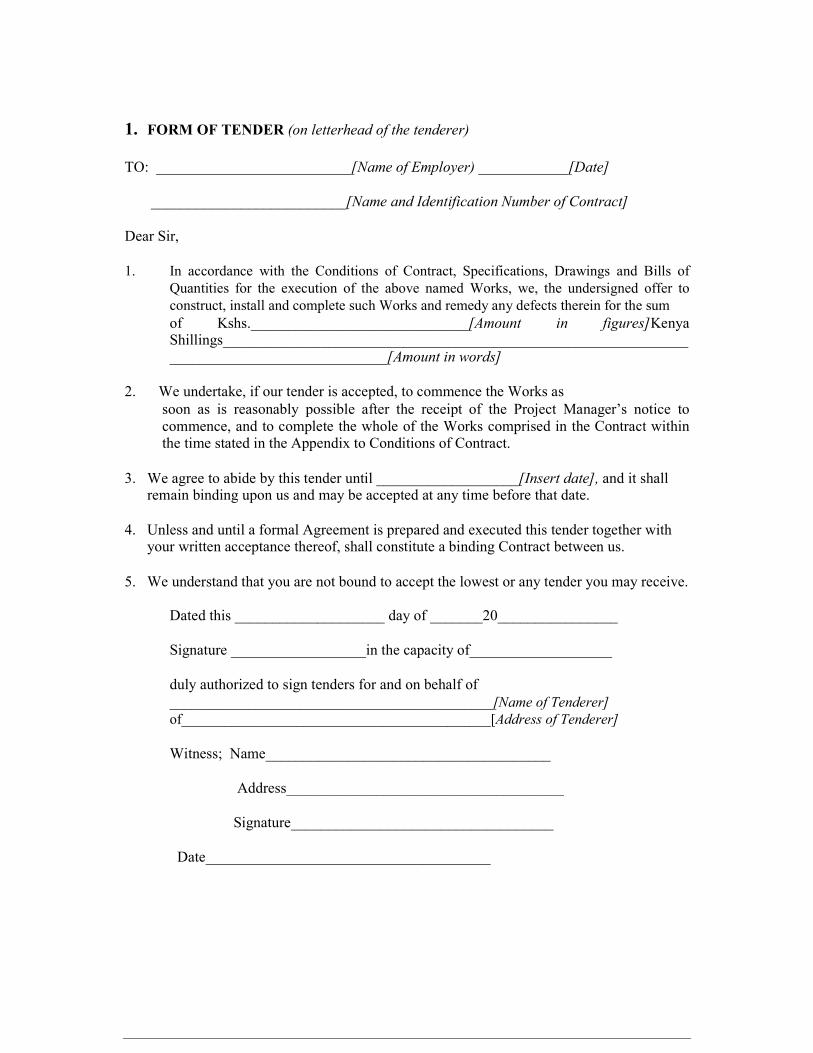
1. FORM OF TENDER (on letterhead of the tenderer) TO: __________________________[Name of Employer) ____________[Date]
__________________________[Name and Identification Number of Contract] Dear Sir, 1. In accordance with the Conditions of Contract, Specifications, Drawings and Bills of Quantities for the execution of the above named Works, we, the undersigned offer to construct, install and complete such Works and remedy any defects therein for the sum of Kshs._____________________________[Amount in figures]Kenya Shillings______________________________________________________________ _____________________________[Amount in words] 2. We undertake, if our tender is accepted, to commence the Works as soon as is reasonably possible after the receipt of the Project Manager’s notice to commence, and to complete the whole of the Works comprised in the Contract within the time stated in the Appendix to Conditions of Contract. 3. We agree to abide by this tender until ___________________[Insert date], and it shall remain binding upon us and may be accepted at any time before that date. 4. Unless and until a formal Agreement is prepared and executed this tender together with your written acceptance thereof, shall constitute a binding Contract between us. 5. We understand that you are not bound to accept the lowest or any tender you may receive. Dated this ____________________ day of _______20________________ Signature __________________in the capacity of___________________ duly authorized to sign tenders for and on behalf of _____________________________________________[Name of Tenderer] of___________________________________________[Address of Tenderer] Witness; Name______________________________________ Address_____________________________________ Signature___________________________________ Date______________________________________

2. APPENDIX TO FORM OF TENDER (This appendix forms part of the tender) CONDITIONS OF CONTRACT CLAUSE AMOUNT Tender Security The tender security shall be 2% of the Tender Sum Amount of Performance Security 10.1 Five (5) percent of Tender Sum (Unconditional Bank Guarantee) in the form of Unconditional Bank Guarantee from a local reputable bank Program to be submitted 14.1 Not later than 14 days after issuance of Order to Commence Cashflow estimate to be submitted 14.3 Not later than 28days after issuance Of Order to Commence Minimum amount of Third Party Insurance 23.2 As per applicable laws in Kenya Period for commencement, from the 41.1 Within 28 days Engineer’s order to commence Time for completion from Commencement 43.1 Six (6) calendar months Date Amount of liquidated damages 47.1 Kes.30,000 per day Limit of liquidated damages 47.1 10% of Contract Value Defect Liability period 49.1 12 months Percentage of Retention 60.5 5% of Interim Payment Certificate Limit of Retention Money 60.5 5% of the contract sum Minimum amount of interim certificates 60.2 Kes.3,000,000.00 Time within which payment to be made after 60.8 56 days Interim Payment Certificate signed by Engineer Time within which payment to be made after 60.8 45 days Final Payment Certificate signed by Engineer Appointer of Arbitrator 67(3) Chartered Institute of Arbitrators – Kenya Chapter Notice to Employer and Engineer 68.2 The Employers address is: PRINCIPAL SECRETARY, STATE DEPARTMENT FOR RRIGATION P O BOX 30028 – 00100 NAIROBI Telex: +254 20 2728703 Email: [email protected]

The Engineer’s address is: IRRIGATION SECRETARY, STATE DEPARTMENT FOR IRRIGATION P.O.BOX 30028-00100 NAIROBI Name of tenderer........................................................................................................................ Signature of Tender…………………………………Date……..........................……………… Stamp...........................................................................................................................................
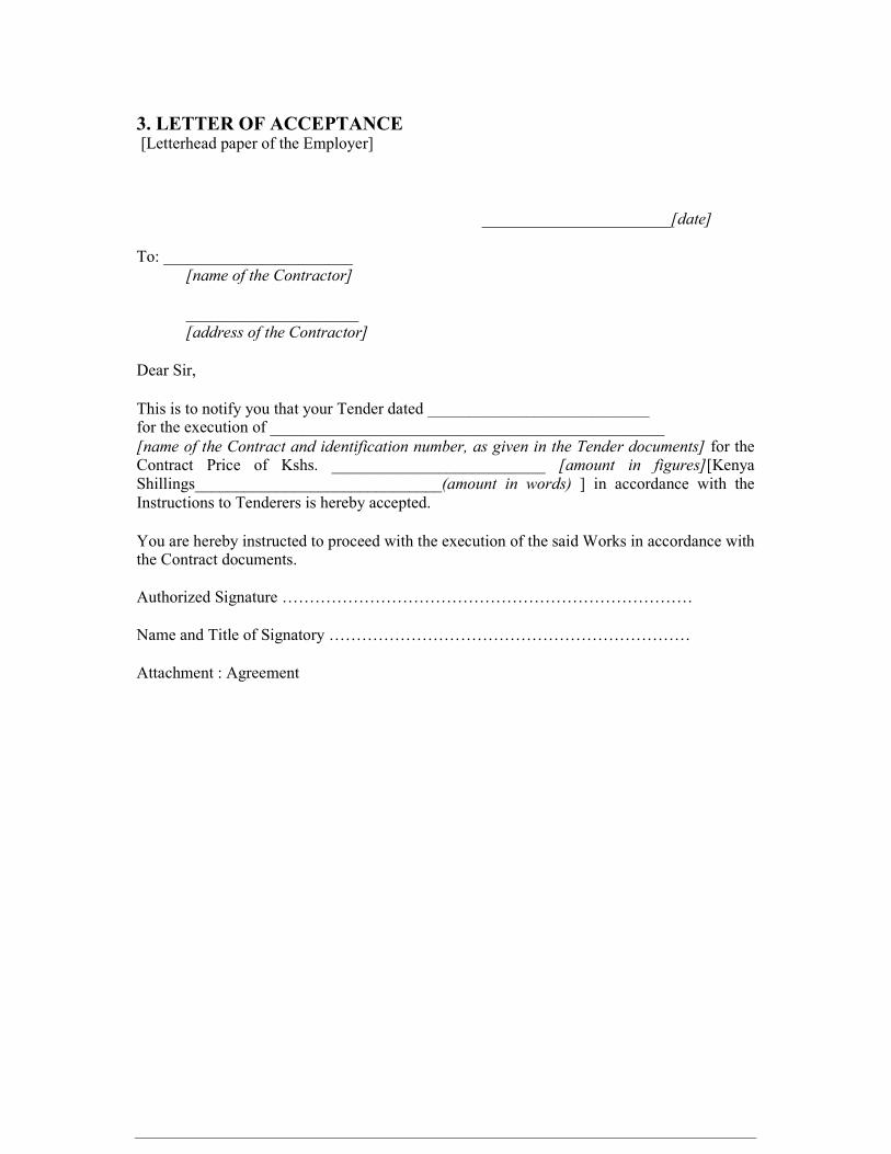
3. LETTER OF ACCEPTANCE [Letterhead paper of the Employer]
_______________________[date] To: _______________________ [name of the Contractor] _____________________ [address of the Contractor] Dear Sir, This is to notify you that your Tender dated ___________________________ for the execution of ________________________________________________
[name of the Contract and identification number, as given in the Tender documents] for the Contract Price of Kshs. __________________________ [amount in figures][Kenya Shillings______________________________(amount in words) ] in accordance with the Instructions to Tenderers is hereby accepted. You are hereby instructed to proceed with the execution of the said Works in accordance with the Contract documents. Authorized Signature ………………………………………………………………… Name and Title of Signatory ………………………………………………………… Attachment : Agreement

4. FORM OF AGREEMENT THIS AGREEMENT, made the _________________ day of ________ 20 ______ between________________________________________________of[or whose registered office is situated at]__________________________________________ (hereinafter called “the Employer”) of the one part AND ________________________________________________________of[or whose registered office is situated at]_________________________________________ (hereinafter called “the Contractor”) of the other part. WHEREAS THE Employer is desirous that the Contractor executes ________________________________________________________________________ (name and identification number of Contract ) (hereinafter called “the Works”) located at______________________________[Place/location of the Works]and the Employer has accepted the tender submitted by the Contractor for the execution and completion of such Works and the remedying of any defects therein for the Contract Price of Kshs___________________________[Amount in figures],Kenya Shillings_____________________________________________[Amount in words]. NOW THIS AGREEMENT WITNESSETH as follows: 1. In this Agreement, words and expressions shall have the same meanings as are respectively assigned to them in the Conditions of Contract hereinafter referred to. 2. The following documents shall be deemed to form and shall be read and construed as part of this Agreement i.e. (i) Letter of Acceptance (ii) Form of Tender (iii) Conditions of Contract Part I (iv) Conditions of Contract Part II and Appendix to Conditions of Contract (v) Specifications (vi) Drawings (vii) Priced Bills of Quantities 3. In consideration of the payments to be made by the Employer to
the Contractor as hereinafter mentioned, the Contractor hereby covenants with the Employer to execute and complete the Works and remedy any defects therein in conformity in all respects with the provisions of the Contract. 4. The Employer hereby covenants to pay the Contractor in consideration of the execution and completion of the Works and the remedying of defects therein, the Contract Price or such other sum as may become payable under the provisions of the Contract at the times and in the manner prescribed by the Contract. IN WITNESS whereof the parties thereto have caused this Agreement to be executed the day and year first before written. The common Seal of _________________________________________________ Was hereunto affixed in the presence of ________________________________ Signed Sealed, and Delivered by the said ______________________________ Binding Signature of Employer ________________________________________ Binding Signature of Contractor _______________________________________ In the presence of (i) Name_______________________________________ Address_____________________________________ Signature___________________________________ [ii] Name _______________________________________ Address_____________________________________ Signature____________________________________
5. TENDER-SECURING DECLARATION FORM [The Bidder shall in this Form in accordance with the Instructions indicated] Date: [insert date (as day month and year) of Bid submission] Tender No.: [insert number of bidding process] To: [insert complete name of purchaser] 1. We understand that, according to your conditions, bids must be supported by a Bid-Securing Declaration. 2. We accept that we will automatically be suspended from being eligible for bidding in any contract with the Borrower for the period of time of five (5) years starting on October
2013 if we are in breach of our obligation(s) under the bid conditions, because we: (a) have withdrawn our Bid during the period of bid validity specified by us in the Bidding Data Sheet; or (b) having been notified of the acceptance of our Bid by the Purchaser during the period of bid validity, (i) fail or refuse to execute the Contract, if required, or (ii) fail or refuse to furnish the Performance Security, in accordance with the ITB. 3. We understand this Bid-Securing Declaration shall expire if we are not the successful Bidder, upon the earlier of (i) our receipt of your notification to us of the name of the successful Bidder; or (ii) twenty-eight days after the expiration of our Tender. 4. We understand that if we are a joint venture, the Bid Securing Declaration must be in the name of the Joint Venture that submits the bid, and the Joint Venture has not been legally constituted at the time of bidding, the Bid Securing Declaration shall be in the names of all future partners as named in the letter of intent. Signed: [insert signature of person whose name and capacity are shown] In the capacity of [insert legal capacity of person signing the Bid-Securing Declaration] Name: [insert complete name of person signing the Bid-Securing Declaration] Duly authorized to sign the bid for and on behalf of: [insert complete name of Bidder] Dated on ____________ day of __________________, _______ [insert date of signing]
6. PERFORMANCE BANK GUARANTEE (UNCONDITIONAL) To: _________________________(Name of Employer) __________________________(Address of Employer)
___________(Date) Dear Sir, WHEREAS ______________________(hereinafter called “the Contractor”) has undertaken, in pursuance of Contract No. _____________ dated _________ to execute _______________ (hereinafter called “the Works”); AND WHEREAS it has been stipulated by you in the said Contract that the Contractor shall furnish you with a Bank Guarantee by a recognised bank for the sum specified therein as security for compliance with his obligations in accordance with the Contract; AND WHEREAS we have agreed to give the Contractor such a Bank Guarantee: NOW THEREFORE we hereby affirm that we are the Guarantor and responsible to you, on behalf of the Contractor, up to a total of Kshs. ________________ (amount of Guarantee in
figures) Kenya Shillings__________________________________________ (amount of Guarantee in words), and we undertake to pay you, upon your first written demand and without cavil or argument, any sum or sums within the limits of Kenya Shillings _________________________ (amount of Guarantee in words) as aforesaid without your needing to prove or to show grounds or reasons for your demand for the sum specified therein. We hereby waive the necessity of your demanding the said debt from the Contractor before presenting us with the demand. We further agree that no change, addition or other modification of the terms of the Contract or of the Works to be performed there under or of any of the Contract documents which may be made between you and the Contractor shall in any way release us from any liability under this Guarantee, and we hereby waive notice of any change, addition, or modification. This guarantee shall be valid until the date of issue of the Certificate of Completion. SIGNATURE AND SEAL OF THE GUARANTOR ___________________ Name of Bank ____________________________________________ Address ________________________________________________ Date ______________________________________________________

7. BANK GUARANTEE FOR ADVANCE PAYMENT To: ________________________ [name of Employer] ___________(Date) ________________________[address of
Employer] Gentlemen, Ref: _______________________________________________[name of Contract] In accordance with the provisions of the Conditions of Contract of the above-mentioned Contract, We,_______________________________________[name and Address of Contractor] (hereinafter called “the Contractor”) shall deposit with _______________________________[name of Employer] a bank guarantee to guarantee his proper and faithful performance under the said Contract in an amount of Kshs._____________[amount of Guarantee in figurers] Kenya Shillings_____________________________________[amount of Guarantee in words]. We, ________________[bank or financial institution], as instructed by the Contractor, agree unconditionally and irrevocably to guarantee as primary obligator and not as Surety merely, the payment to ___________________________[name of Employer] on his first demand without whatsoever right of objection on our part and without his first claim to the Contractor, in the amount not exceeding Kshs________________________[amount of Guarantee in figures] Kenya Shillings _____________________________________________________________[amount of Guarantee in words], such amount to be reduced periodically by the amounts recovered by you from the proceeds of the Contract. We further agree that no change or addition to or other modification of the terms of the Contract or of the Works to be performed there under or of any of the Contract documents which may be made between ________________________[name of Employer] and the Contractor, shall in any way release us from any liability under this guarantee, and we hereby waive notice of any such change, addition or modification. No drawing may be made by you under this guarantee until we have received notice in writing from you that an advance payment of the amount listed above has been paid to the Contractor pursuant to the Contract. This guarantee shall remain valid and in full effect from the date of the advance payment under the Contract until ______________________________________________(name of Employer) receives full payment of the same amount from the Contract. Yours faithfully,

Signature and Seal __________________________________________________ Name of the Bank or financial institution ______________________________ Address ______________________________________________________________ Date _________________________________________________________________ Witness: Name: ____________________________________________________ Address: __________________________________________________ Signature: ________________________________________________ Date: _____________________________________________________

8. TENDER QUESTIONNAIRE Please fill in block letters. 1. Full names of tenderer ……………………………………………………………………………………… 2. Full address of tenderer to which tender correspondence is to be sent (unless an agent has been appointed below) ……………………………………………………………………………………… 3. Telephone number (s) of tenderer ……………………………………………………………………………………… 4. Telex address of tenderer ……………………………………………………………………………………… 5. Name of tenderer’s representative to be contacted on matters of the tender during the tender period ……………………………………………………………………………………… 6. Details of tenderer’s nominated agent (if any) to receive tender notices. This is essential if the tenderer does not have his registered address in Kenya (name, address, telephone, telex) ……………………………………………………………………………………… Signature of Tenderer:................................................................................................. Make copy and deliver to :_____________________( Name of Employer)

9. CONFIDENTIAL BUSINESS QUESTIONNAIRE You are requested to give the particulars indicated in Part 1 and either Part 2 (a), 2 (b) or 2 (c) and 2 (d) whichever applies to your type of business. You are advised that it is a serious offence to give false information on this Form. Part 1 – General Business Name ……………………………………………………………………… Location of business premises; Country/Town………………………. Plot No……………………………………… Street/Road ………………………… Postal Address……………………………… Tel No……………………………….. Nature of Business………………………………………………………………….. Current Trade Licence No…………………… Expiring date………………… Maximum value of business which you can handle at any time: Ksh.……………………….. Name of your bankers……………………………………………………………… Branch………………………………………………………………………………… Part 2 (a) – Sole Proprietor Your name in full…………………………………… Age………………………… Nationality………………………………… Country of Origin………………… *Citizenship details ………………………………………………………………… Part 2 (b) – Partnership Give details of partners as follows:
Name in full Nationality Citizenship Details Shares 1…………………………………………………………………………………… 2…………………………………………………………………………………… 3…………………………………………………………………………………… Part 2(c) – Registered Company: Private or public……………………………………………………………
State the nominal and issued capital of the Company- Nominal Kshs………………………………………………………………… Issued Kshs…………………………………………………………………… Give details of all directors as follows: Name in full . Nationality. Citizenship Details*. Shares. 1. ……………………………………………………………………………………… 2. ……………………………………………………………………………………… 3. ……………………………………………………………………………………… 4.……………………………………………………………………………………… Part 2(d) – Interest in the Firm: Is there any person / persons in …………… ………(Name of Employer) who has interest in this firm? Yes/No………………………(Delete as necessary) I certify that the information given above is correct. ………………………
(Title)
……………………… (Signature)
………………… (Date) * Attach proof of citizenship
10. SCHEDULE OF LABOUR:- BASIC RATES (Reference: Clause 70 of Conditions of Contract) LABOUR CATEGORY UNIT RATES (MONTH/SHIFT/HOUR) Categories to be generally in accordance with those used by the Kenya Building Construction and Engineering and Allied Trades Workers’ Union.
11. DETAILS OF SUB-CONTRACTORS If the Tenderer wishes to sublet any portions of the Works under any heading, he must give below details of the sub-contractors he intends to employ for each portion. Failure to comply with this requirement may invalidate the tender. (1) Portion of Works to be sublet: ……………………………… (i) Full name of Sub-contractor and address of head office: ……………………………… ……………………………… ii) Sub-contractor’s experience of similar works carried out in the last 3 years with Contract value: ……………………………… ……………………………… ……………………………… (2) Portion of Works to sublet: ……………………………… (i) Full name of sub-contractor and address of head office: ……………………………… ……………………………… ……………………………… (ii) Sub-contractor’s experience of similar works carried out in the last 3 years with contract value: …………………………… …………………………… ________________ _______________________ [Signature of Tenderer) Date
12. FORM OF WRITTEN POWER-OF-ATTORNEY The Tenderer consisting of a joint venture shall state here below the name and address of his representative who is authorised to receive on his behalf correspondence in connection with the Tender. ……………………………………………………………… (Name of Tenderer’s Representative in block letters) ……………………………………………………………… (Address of Tenderer’s Representative) ……………………………………………………………… (Signature of Tenderer’s Representative)
13. KEY PERSONNEL DESIGNATION NAME NATIONALITY SUMMARY OF QUALIFICATIONS AND EXPERIENCE Headquarters: 1. Director 2. 3. 4. 5. etc. Site Office: 1. Site Superintendent 2. 3. 4. 5. etc. I certify that the above information is correct. ………………………… (Title) …………………… (Signature) ……………….. (Date)

14. SCHEDULE OF COMPLETED WORKS CARRIED OUT BY THE TENDERER
IN THE FIVE (5) YEARS DESCRIPTION OF TOTAL VALUE CONTRACT YEAR COMPLETED WORKS AND OF WORKS PERIOD CLIENT (KSHS) (YEARS) I certify that the above Civil Works were successfully carried out and completed by ourselves. ………………………… (Title) ………………………… (Signature) ……………… (Date)
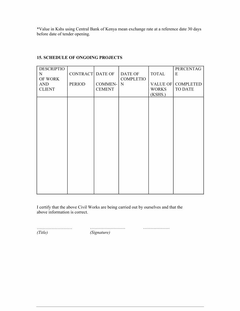
*Value in Kshs using Central Bank of Kenya mean exchange rate at a reference date 30 days before date of tender opening. 15. SCHEDULE OF ONGOING PROJECTS DESCRIPTION CONTRACT DATE OF DATE OF TOTAL PERCENTAGE OF WORK AND PERIOD COMMEN- COMPLETION VALUE OF COMPLETED CLIENT CEMENT WORKS TO DATE (KSHS.) I certify that the above Civil Works are being carried out by ourselves and that the above information is correct. …………………… (Title)
…………………… (Signature)
………………
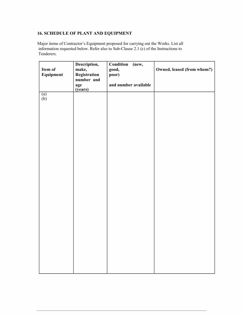
16. SCHEDULE OF PLANT AND EQUIPMENT Major items of Contractor’s Equipment proposed for carrying out the Works. List all information requested below. Refer also to Sub-Clause 2.1 (c) of the Instructions to Tenderers.
Item of Description, make,
Condition (new, good, Owned, leased (from whom?)
Equipment Registration poor) number and age and number available (years) (a) (b)

17. OTHER SUPPLEMENTARY INFORMATION 1. Financial reports for the last five years, balance sheets, profit and loss statements, auditors’ reports etc. List them below and attach copies. ……………………………………………………………………… ……………………………………………………………………… ……………………………………………………………………… 2. Evidence of access to financial resources to meet the qualification requirements. Cash in hand, lines of credit etc. List below and attach copies of supporting documents ……………………………………………………………………… ……………………………………………………………………… ……………………………………………………………………… 3. Name, address , telephone, telex, fax numbers of the Tenderer’s Bankers who may provide reference if contacted by the Employer. ………………………………………………………………………… ………………………………………………………………………… ………………………………………………………………………… 4. Proposed Program (work method and schedule). Descriptions, drawings, and charts, as necessary, to comply with the requirements of the bidding documents ………………………………………………………………………… ………………………………………………………………………… ………………………………………………………………………… ………………………………………………………………………… ………………………………………………………………………… 5. Information on current litigation in which the Tenderer is involved. OTHER PARTY (IES) CAUSE OF DISPUTE AMOUNT INVOLVED (KSHS)
I certify that the above information is correct. …………………… ……………………… ……………………… Title
Signature
Date
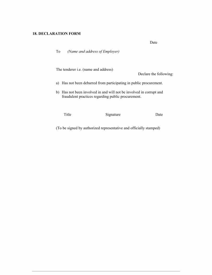
18. DECLARATION FORM Date To (Name and address of Employer) The tenderer i.e. (name and address) Declare the following: a) Has not been debarred from participating in public procurement. b) Has not been involved in and will not be involved in corrupt and fraudulent practices regarding public procurement. Title Signature Date (To be signed by authorized representative and officially stamped)

19. LETTER OF NOTIFICATION OF AWARD Address of Procuring Entity _____________________ _____________________ To: RE: Tender No. Tender Name This is to notify that the contract/s stated below under the above mentioned tender have been awarded to you. 1. Please acknowledge receipt of this letter of notification signifying your acceptance. 2. The contract/contracts shall be signed by the parties within 30 days of the date of this letter but not earlier than 14 days from the date of the letter. 3. You may contact the officer(s) whose particulars appear below on the subject matter of this letter of notification of award. (FULL PARTICULARS) SIGNED FOR ACCOUNTING OFFICER