draft sap 2009 main document
TRANSCRIPT
8/14/2019 Draft SAP 2009 Main Document
http://slidepdf.com/reader/full/draft-sap-2009-main-document 1/91
DRAFT SAP 2009 version 9.90 (April 2009)
0
DRAFT SAP 2009
The Government's Standard Assessment
Procedure for Energy Rating of Dwellings
DRAFT
2009 edition
This document describes SAP 2009 version 9.90, dated ___________. SAP assessors and other
users should ensure that they are using the latest version of the document. Information on this and
any updates will be published on the BRE website below.
Published on behalf of DECC by:
BRE
Garston, Watford WD25 9XX
Enquiries and comments to [email protected]
www.bre.co.uk/sap2009 © Crown copyright 2009

8/14/2019 Draft SAP 2009 Main Document
http://slidepdf.com/reader/full/draft-sap-2009-main-document 2/91
DRAFT SAP 2009 version 9.90 (April 2009)
1
Published on behalf of DECC by: BRE, Garston, Watford WD25 9XX
© Crown copyright 2009

8/14/2019 Draft SAP 2009 Main Document
http://slidepdf.com/reader/full/draft-sap-2009-main-document 3/91
DRAFT SAP 2009 version 9.90 (April 2009)
2
Contents
SUMMARY 3
INTRODUCTION 4
SCOPE OF THE SAP PROCEDURE 5
GENERAL PRINCIPLES 5
CALCULATION PROCEDURE AND CONVENTIONS 7
1 Dwelling dimensions 7
2 Ventilation rate 8 2.1 Chimneys and flues 9 2.2 Fans and passive vents 9 2.3 Pressurisation test 9 2.4 Draught lobby 10 2.5 Sheltered Sides 10 2.6 Mechanical ventilation 11
3 Heat losses 13 3.1 U-values of opaque elements 13 3.2 Window U-values 13 3.3 U-values of elements adjacent to an unheated space 14 3.4 Thermal bridging 17 3.5 Dwellings that are part of larger premises 17 3.6 Curtain walling 17 3.7 Party walls 18
4 Domestic hot water 18 4.1 Distribution loss 18 4.2 Storage loss 18 4.3 Community schemes 19 4.4 Solar collector 19 4.5 Alternative DHW heating systems 19
5 Internal gains 19
6 Solar gains and utilisation factor 20 6.1 Solar gains for openings 20 6.2 Openings for which solar gain is included 20 6.3 More than one glazing type 21 6.4 Utilisation factor 21 6.5 Solar gain in summer 21
7 Mean internal temperature 21 7.1 Living area fraction 21
8 Climatic data 21
9 Space heating requirements 21 9.1 Heating systems 21 9.2 Heating system efficiency (space and DHW) 22 9.3 Heating controls 24
10 Space cooling requirements 26
11 Total energy use and fuel costs 27 11.1 Energy use 27 11.2 Fuel prices 27 11.3 Electricity tariff 27 11.4 Main fuel types 27

8/14/2019 Draft SAP 2009 Main Document
http://slidepdf.com/reader/full/draft-sap-2009-main-document 4/91
DRAFT SAP 2009 version 9.90 (April 2009)
3
11.5 Secondary fuel types 29 11.6 Water heating fuel types 29 11.7 Electricity for pumps and fans 29 11.8 Electricity for lighting 29
12 Energy cost rating 29
13 Carbon dioxide emissions and primary energy 30 14 Building regulations and dwelling emissions rate (DER) 30
15 CO2 emissions associated with appliances and cooking and site-wide electricity generation
technologies 31
REFERENCES 32
LIST OF STANDARDS REFERRED TO IN THIS DOCUMENT 33
Appendix A : Main and secondary heating systems 34
Appendix B : Gas and oil boiler systems, boilers with a thermal store, and range cooker boilers 37
Appendix C : Community heating, including schemes with Combined Heat and Power (CHP) andschemes that recover heat from power stations. 41
Appendix D : Method of determining seasonal efficiency values for gas and oil boilers 46
Appendix E : Method of determining seasonal efficiency for gas, oil and solid fuel room heaters 55
Appendix F : Electric CPSUs 57
Appendix G : Heat pumps 58
Appendix H : Solar water heating 60
Appendix I (not used) 65
Appendix J : Seasonal efficiency for solid fuel boilers from test data 66
Appendix K : Thermal bridging 67 Appendix L : Energy for lighting and electrical appliances 69
Appendix M : Energy from Photovoltaic (PV) technology, small and micro wind turbines and small-
scale hydro-electric generators 72
Appendix N : Micro-cogeneration (also known as micro-CHP) 76
Appendix O (not used) 80
Appendix P : Assessment of internal temperature in summer 81
Appendix Q : Special features and specific data 87
Appendix R : Reference values 88
SAP Worksheet (version 9.90)
Tables
SUMMARYThis manual describes the Government’s Standard Assessment Procedure (SAP) for assessing the energy
performance of dwellings. The indicators of energy performance are energy consumption per unit floorarea, an energy cost rating (the SAP rating), an Environmental Impact rating based on CO2 emissions (the
EI rating) and a Dwelling CO2 Emission Rate (DER).
The SAP rating is based on the energy costs associated with space heating, water heating, ventilation and
lighting, less cost savings from energy generation technologies. It is adjusted for floor area so that it is

8/14/2019 Draft SAP 2009 Main Document
http://slidepdf.com/reader/full/draft-sap-2009-main-document 5/91
DRAFT SAP 2009 version 9.90 (April 2009)
4
essentially independent of dwelling size for a given built form. The SAP rating is expressed on a scale of 1
to 100, the higher the number the lower the running costs.
The Environmental Impact rating is based on the annual CO2 emissions associated with space heating,
water heating, ventilation and lighting, less the emissions saved by energy generation technologies. It is
adjusted for floor area so that it is essentially independent of dwelling size for a given built form. The
Environmental Impact rating is expressed on a scale of 1 to 100, the higher the number the better thestandard.
The Dwelling CO2 Emission Rate is a similar indicator to the Environmental Impact rating, which is used
for the purposes of compliance with building regulations. It is equal to the annual CO2 emissions per unit
floor area for space heating, water heating, ventilation and lighting, less the emissions saved by energy
generation technologies, expressed in kg/m²/year.
The method of calculating the energy performance and the ratings is set out in the form of a worksheet,accompanied by a series of tables. The methodology is compliant with the Energy Performance of
Buildings Directive. The calculation should be carried out using a computer program that implements the
worksheet and is approved for SAP calculations (BRE approves SAP software on behalf of the Department
for Energy and Climate Change; the Department for Communities and Local Government; the Scottish
Government; the National Assembly for Wales; and the Department of Finance and Personnel).
INTRODUCTIONThe Standard Assessment Procedure (SAP) is adopted by Government as the UK methodology for
calculating the energy performance of dwellings.
The calculation is based on the energy balance taking into account a range of factors that contribute to
energy efficiency:
• materials used for construction of the dwelling
• thermal insulation of the building fabric
• ventilation characteristics of the dwelling and ventilation equipment
• efficiency and control of the heating system(s)• solar gains through openings of the dwelling
• the fuel used to provide space and water heating, ventilation and lighting
• renewable energy technologies
The calculation is independent of factors related to the individual characteristics of the household
occupying the dwelling when the rating is calculated, for example:
• household size and composition;
• ownership and efficiency of particular domestic electrical appliances;
• individual heating patterns and temperatures.
Ratings are not affected by the geographical location, so that a given dwelling has the same rating in all
parts of the UK.
The procedure used for the calculation is based on the BRE Domestic Energy Model (BREDEM[ 1,2,3,4,5]
),which provides a framework for the calculation of energy use in dwellings. The procedure is consistent with
the standard BS EN ISO 13790.
The Standard Assessment Procedure was first published by the then DOE and BRE in 1993 and in amended
form in 1994, and conventions to be used with it were published in 1996 and amended in 1997. Revised
versions were published in 1998, 2001 and 2005.
The present edition is SAP 2009 in which:- space and water heating are calculated on a monthly, instead of an annual, basis
- space cooling is included
- thermal mass of construction elements is explicit rather than implicit
- energy used for domestic hot water has been revised
- weather data has been updated - CO2 emissions factors have been extensively revised

8/14/2019 Draft SAP 2009 Main Document
http://slidepdf.com/reader/full/draft-sap-2009-main-document 6/91
DRAFT SAP 2009 version 9.90 (April 2009)
5
- the calculation of boiler efficiency from test data has been amended
- internal heat gains have been revised and a reduced level of gains is proposed for design purposes
Reduced Data SAP is not being amended in this revision and RdSAP assessments will continue to use
SAP 2005 version 9.82 for the time being. It is anticipated that RdSAP will be revised following the
implementation of SAP 2009.
SCOPE OF THE SAP PROCEDUREThe procedure is applicable to self-contained dwellings (of any size).
For flats, it applies to the individual flat and does not include common areas such as access corridors.
Note: Common areas of blocks of flats such as heated access corridors, and other buildings (even though
used for residential purposes, e.g. nursing homes) are assessed using procedures for non-domestic
buildings.
Where part of an accommodation unit is used for commercial purposes (e.g. as an office or shop), this partshould be included as part of the dwelling if the commercial part could revert to domestic use on a change
of occupancy. That would be applicable where:
- there is direct access between the commercial part and the remainder of the accommodation, and
- all is contained within the same thermal envelope, and
- the living accommodation occupies a substantial proportion of the whole accommodation unit.
Where a self-contained dwelling is part of a substantially larger building, where the remainder of the
building would not be expected to revert to domestic use, the dwelling is assessed by SAP and the
remainder by procedures for non-domestic buildings.
GENERAL PRINCIPLESInput precision and rounding Data should be entered into calculation software as accurately as possible, although it is unnecessary to go
beyond 3 significant figures (and some product data may only be available to lesser precision).
Input data
Various tables of performance data are provided as part of this document. The tables are used when specific
performance information on the product or system is not available. However, when specific performance
information is available for the following items, it should be used in preference to data from the tables,
particularly in the new build context.
U-values – walls, floors, roofs
For new build, U-values should be calculated on the basis of the actual construction.
Thermal mass
The Thermal Mass Parameter (TMP) is required for heating and cooling calculations. It is defined as the
sum of (area times heat capacity) over all construction elements divided by total floor area. It can be
obtained from the actual construction elements of walls, floors and roofs (including party and internal walls,
floors and ceilings). For further details see Table 1c.
Linear thermal transmittance (Ψ-values)
Ψ-values are used for thermal bridging. There are three possibilities.a) The use of a global factor, which is multiplied by the total exposed surface area, as described in
Appendix K.
b) On the basis of the length of each junction and the default Ψ-values in Table K1.
c) On the basis of the length of each junction and user-supplied Ψ-values. It is not necessary to supply
Ψ-value for each junction type – values from Table K1 can be mixed with user-supplied values.

8/14/2019 Draft SAP 2009 Main Document
http://slidepdf.com/reader/full/draft-sap-2009-main-document 7/91
DRAFT SAP 2009 version 9.90 (April 2009)
6
Window data
Window U-values and g-values (total solar energy transmittance) can be from a certified window energy
rating*
or manufacturers' declaration. Both values are needed (for the calculation of respectively heat lossand solar gain).
Values of light transmittance (gL) are given in Table 6b for calculation of lighting energy requirements as
set out in Appendix L.
For new dwellings and other cases where solar gain provides a significant part of heating requirements theframe factor (representing the glazed fraction of the window) is important in determining solar gain. Frame
factors should be assigned per window (or per group of similar windows) particularly where window areas
differ on different facades on the dwelling. Default values are given in Table 6c.
Boiler efficiency – gas and oil
Boiler efficiency can be from the boiler efficiency database (preferably) or from a manufacturer'sdeclaration given in the terms stated in D3 or D6.
Boiler efficiency – solid fuel
Boiler efficiency can be from the boiler efficiency database (preferably) or from a manufacturer's
declaration given in the terms stated in D3.
Heat pumps
It is intended to add data on heat pumps to the database before the implementation of SAP 2009.
Efficiency of gas/oil/solid fuel fires and room heaters
Efficiency can be from a manufacturer's declaration given in terms of E2.
Standing loss – cylinders, thermal stores and CPSUs (includes both gas and electric CPSUs)
The manufacturer's declared loss obtained in terms of the applicable BS and expressed in kWh/day, can be
used in place of data from Table 2. (Tables 2a and 2b are applied to declared loss as well as to loss from
Table 2).
Pressure test resultThe result of a pressure test can be used instead of the default calculations of infiltration. In the case of a
dwelling not yet built, a design value of air permeability can be used subject to the requirements of building
regulations that apply in the administration where the dwelling will be constructed.
Solar collector performanceThe zero-loss collector efficiency and the collector's linear heat loss coefficient can be used if obtained from
test results.
Specific fan power and ventilation heat exchanger efficiency
Measured values of specific fan power for these mechanical ventilation systems:
- positive input ventilation from outside (not loft)
- mechanical extract
- balancedand of heat exchanger efficiency for MVHR systems, can be used in place of the default values in Table 4g
for those systems that are listed on www.sap-appendixq.org.uk .
Existing properties
The SAP calculation procedure for existing properties follows that for new dwellings. However, some of
the data items are usually defaulted or inferred. For further details see Appendix S of SAP 2005 version
9.82.
The calculation is concerned with the assessment of the dwelling itself, as used by standard or typical
occupants, and not affected by the way current occupants might use it. Thus, for example, the living room
fraction is based on the original design concept and not on the rooms the current occupants heat.
* Operated by the British Fenestration Rating Council

8/14/2019 Draft SAP 2009 Main Document
http://slidepdf.com/reader/full/draft-sap-2009-main-document 8/91
DRAFT SAP 2009 version 9.90 (April 2009)
7
CALCULATION PROCEDURE AND CONVENTIONSThe method of calculating the energy performance is set out in the form of a worksheet, accompanied by a
series of tables. A calculation should follow the numbered entries in the worksheet sequentially. Some
entries are obtained by carrying forward earlier entries, other entries are obtained, using linear interpolation
where appropriate, by reference to Tables 1 to 15 or from user-supplied data. The following notes oncalculations and conventions should be read in conjunction with the worksheet.
The worksheet is intended as a form of describing the calculation, to be used for implementing the
calculation into computer software, rather than for manual calculations.
1 DWELLING DIMENSIONS
The boundary of the heated space consists of all the building elements separating it from externalenvironment or from adjacent dwellings or unheated spaces. Any internal elements (internal partition walls
or intermediate floors within the dwelling) are disregarded for the purposes of establishing areas.
Dimensions refer to the inner surfaces of the elements bounding the dwelling. Thus floor dimensions are
obtained by measuring between the inner surfaces of the external or party walls, disregarding the presence
of any internal walls.
Storey height is the total height between the ceiling surface of a given storey and the ceiling surface of the
storey below. For a single storey dwelling, or the lowest floor of a dwelling with more than one storey, the
measurement should be from floor surface to ceiling surface.
Floor area should be measured as the actual floor area, i.e. if the height of a room extends to two storeys or
more only the actual accessible floor area should be used for the calculations. However, as an exception to
this rule in the case of stairs, the floor area should be measured as if there were no stairs but a floor in their
place at each level.
In general, rooms and other spaces, such as built-in cupboards, should be included in the calculation of the
floor area where these are directly accessible from the occupied area of the dwelling. However unheated
spaces clearly divided from the dwelling should not be included. The following provides specific guidance:
Porches:
• should be included if they are heated by fixed heating devices;
• should be included if there is direct access into the dwelling but no separating door, whether
heated or not;
• should not be included if they are unheated and there is a separating door into the dwelling. In
this context ‘porch’ means an addition protruding from the line of the external wall of the
dwelling; an entrance lobby that is within such line should be included .
Conservatories:
• should not be included if they are separated from the dwelling according to the definition in
3.3.3• should be included as part of the dwelling if they are not separated.
Store rooms and utility rooms:
• should be included if they are directly accessible from the occupied area of the dwelling,
whether heated or not;
• should not be included if they are unheated and accessible only via a separate external door.
Basements:
• should be included only if consisting of heated and habitable rooms.
Garages:
• should be included if heating is provided within the garage from the main central heating
system;

8/14/2019 Draft SAP 2009 Main Document
http://slidepdf.com/reader/full/draft-sap-2009-main-document 9/91
DRAFT SAP 2009 version 9.90 (April 2009)
8
• should not be included where the garage is thermally separated from the dwelling and is not
heated by the central heating system
Attics:
• should be included if they are habitable rooms, accessed by a fixed staircase.
• roof spaces (even though within the insulated envelope, i.e. where the roof insulation is
provided at rafter level) should not be included unless they are habitable rooms accessed by afixed staircase.
When porches or integral garages are not included in floor area, the door and part of the wall between the
dwelling and these structures are adjacent to an unheated space and their U-values should be adjusted where
appropriate (see section 3.3).
In flats, if corridors and stairwells are heated, treat walls between the flat and heated corridors/stairwells asnon-heat loss walls (i.e. assuming the same temperature on either side of the walls).
No special treatment should be given in cases where a central heating boiler is located in an unheated
garage or attic (i.e. the floor area used for the assessment should be the same as if the boiler were in the
kitchen or a utility room).
Pitched roofs
There are three main types of pitched roof construction:
1. pitched roof with insulation at ceiling level, insulated between (and perhaps also above) joists;
2. pitched roof insulated at rafter level (no insulation at ceiling level), insulated between and/or above
rafters ("warm roof"), with a non-ventilated loft space but with a ventilated space between the
insulation and the roof covering;
3. pitched roof insulated either at ceiling level or at rafter level, with roof space converted into habitable
space.
a) Insulation at ceiling level b) Insulation at rafter level
In the cases of a) and b) the roof space should not be treated as a separate storey.
c) Room in roof built into a d) Room in roof built into a
pitched roof insulated at rafter level pitched roof insulated at ceiling level
In the cases of c) and d) the floor area of the roof space that is converted into habitable space should be
treated as a separate storey.
2 VENTILATION RATEThe ventilation air change rate is the rate at which outside air enters/leaves a building.
Cold roof space
Ventilated
spacesRoom in roof
Warm roof space

8/14/2019 Draft SAP 2009 Main Document
http://slidepdf.com/reader/full/draft-sap-2009-main-document 10/91
DRAFT SAP 2009 version 9.90 (April 2009)
9
SAP requires a reasonable estimate of the air change rate in order to calculate the overall heating
requirement. The actual ventilation rate depends on a large number of factors, many of which may not beknown precisely (e.g. permeability of materials and inadvertent gaps and openings in the structure) and in
most cases cannot be assessed from a site survey or from plans.
The infiltration rate can be assessed either from pressurisation test or, in the absence of pressure test, usingthe SAP algorithm as defined by (11) to (18) of the worksheet.
Whether or not a pressurisation test has been carried out, the ventilation calculation requires the information
on chimneys, fans, open flues and passive vents. Chimneys, fans, open flues and passive vents (blocked off
during a pressurisation test but open in practice) should be counted in (9a) to (9d) of the worksheet.
Ventilation rates for chimneys, flues, fans and passive vents, flueless gas fires and passive stack ventilators
are given in Table 2.1 below.
Table 2.1 Ventilation rates
Item Ventilation rate m3 /hour
Chimney 40
Open flue 20Fan 10
Passive vent 10
Flueless gas fire 40
2.1 Chimneys and flues
Ventilation rates for chimneys and flues should be counted only when they are unrestricted and suitable for
use.
For the purposes of the SAP a chimney is defined as a vertical duct for combustion gases of diameter
200 mm or more (or a rectangular duct of equivalent size). Vertical ducts with diameter less than 200 mm
should be counted as flues. The following are also counted as flues:
• a chimney for solid fuel appliances with controlled flow of the air supply;
• a flexible flue liner sealed into a chimney;
• a chimney fitted with a damper;
• a chimney fitted with an open-flue gas fire where the flue products outlet is sealed to the chimney;
• a blocked up fireplace fitted with ventilators (if ventilator area does not exceed 30 000 mm²)
Ventilation rates should be included only for open flues; they should not be included for room-sealed
boilers or room heaters. Ventilation rates for specific closed appliances may be introduced.
2.2 Fans and passive vents
Intermittent-running extract fans which exhaust air (typically from the kitchen and bathroom), including
cooker hoods and other independent extractor fans, should be included in the 'number of fans’ category. For
continuously running fans see section 2.6.
Passive stack ventilators (passive vents) are an alternative to extract fans. Such systems comprise extract
grilles connected to ridge terminals by ducts. Such systems should be supplied with air bricks or trickle
vents for air ingress. It is the number of extract grilles that should be used in the calculation.
Trickle vents or air bricks alone do not count as passive vents and should not be included in thecalculation.
2.3 Pressurisation test
A pressurisation test of a dwelling is carried out by installing a fan in the doorway of the principal entrance
to the dwelling, sealing all flues and chimneys, and determining the air flow rate required to maintain anexcess pressure of 50 pascals (Pa). The pressurisation test should be carried out in accordance with BS EN

8/14/2019 Draft SAP 2009 Main Document
http://slidepdf.com/reader/full/draft-sap-2009-main-document 11/91
DRAFT SAP 2009 version 9.90 (April 2009)
10
13829. The air permeability measured in this way, q50, expressed in cubic metres per hour per square metre
of envelope area is divided by 20 for use in the worksheet (to give an estimate of the air change rate at
typical pressure differences). In this case (11) to (18) of the worksheet are not used.*
2.4 Draught lobby
A draught lobby is an arrangement of two doors that forms an airlock on the main entrance to the dwelling.
To be included, the enclosed space should be at least 2 m2 (floor area), it should open into a circulationarea, and the door arrangement should be such that a person with a push-chair or similar is able to close theouter door before opening the inner door. It may be heated or unheated and may provide access to a
cloakroom (but it should not be counted as a draught lobby if it provides access to other parts of the
dwelling).
A draught lobby should only be specified if there is a draught lobby to the main entrance of the dwelling. If the main entrance has no draught lobby but, for example, a back door does, then no draught lobby should be
specified.
An unheated draught lobby in the form of an external porch should not be counted as part of the area of the
dwelling. However, the door between the dwelling and the porch is a ‘semi-exposed’ element and its U-
value should be calculated accordingly (see section 3.3).
Flats with access via an unheated stairwell or corridor should be classified as having a draught lobby.
2.5 Sheltered Sides
A side of a building is sheltered if there are adjacent buildings or tree-height hedges which effectively
obstruct the wind on that side of the building. A side should be considered sheltered if all the following
apply:
- the obstacle providing the shelter is at least as high as the ceiling of the uppermost storey of the dwelling;
- the distance between the obstacle and the dwelling is less than five times the height of the obstacle;
- the width of the obstacle (or the combined width of several obstacles) is such that it subtends an angle of at least 60° within the central 90° when viewed from the middle of the wall of the dwelling that faces the
obstacle - see Figure 1
Obstacle
Dwelling
Only this angle counts.
It must be at least 60°
within the central 90° at the wall
centre
Figure 1 Shelter angle
Two partially sheltered sides should be counted as one sheltered side. Architectural planting does not count
as shelter unless it actually exists (even though shown as mature trees on drawings).
Any party wall should be counted as a sheltered side.
For new dwellings it will often be appropriate to assume that two sides of the dwelling are sheltered.
*
In the case of a new dwelling, subject to the requirements of building regulations that apply in theadministration where the dwelling will be constructed, a design value or a specified value of air
permeability can be used for the calculation.

8/14/2019 Draft SAP 2009 Main Document
http://slidepdf.com/reader/full/draft-sap-2009-main-document 12/91
DRAFT SAP 2009 version 9.90 (April 2009)
11
2.6 Mechanical ventilation
Mechanical ventilation systems use continually running fans. They can be input-only, extract-only or
balanced (input and extract).
2.6.1 Mechanical ventilation systems
(a) Positive input ventilation (PIV)
Positive input ventilation is a fan driven ventilation system, which often provides ventilation to the dwelling
from the loft space. The SAP calculation procedure for systems which use the loft to pre-heat theventilation air is the same as for natural ventilation, including 20 m³/h ventilation rate equivalent to two
extract fans or passive vents. (The energy used by the fan is taken as counterbalancing the effect of using
slightly warmer air from the loft space compared with outside).
Some positive input ventilation systems supply the air directly from the outside and the procedure for these
systems is the same as for mechanical extract ventilation.
(b) Mechanical extract ventilation (MEV)
MEV is a fan driven ventilation system, which only extracts air from the dwelling. The SAP calculation is
based on a throughput of 0.5 air changes per hour through the mechanical system, plus infiltration.
MEV can be either:- centralised: air is extracted from wet rooms via ducting and expelled by means of a central fan., or
- decentralised: air is extracted by continuously-running fans in each wet room.
(c) Balanced whole house mechanical ventilation
Balanced ventilation provides fresh air to habitable rooms in the dwelling and extracts exhaust air from wet
rooms.
A balanced system without heat recovery extracts from wet rooms via ducting and expelled by a central fan.
Air is also supplied to habitable rooms, either via ducting and a central fan or by individual supply air fans
in each habitable room.
In a balanced system with heat recovery (MVHR) both the extract and supply air are provided via ducting,
with a heat exchanger between the outgoing and incoming air.
2.6.2 Data required
Centralised MEV: The system's Specific Fan Power (SFP) and whether the ducting is rigid or flexible.
Decentralised MEV: SFP of each fan together with the fan's ducting arrangements (the fan can be in the
ceiling of the room with a duct to the outside, or in a duct, or in a through-wall arrangement with no duct).
Balanced mechanical ventilation without heat recovery. SFP taking account of all fans and whether the
ducting is rigid or flexible.
MVHR. SFP as a single value for the system as a whole, the efficiency of the heat exchanger, whether the
ducting is rigid or flexible and whether the ducting is insulated (where outside the building's insulated
envelope).
For systems that have been tested according to the Appendix Q procedures for mechanical ventilationsystems (details at www.sap-appendixq.org.uk ) the tested data should be used for the calculations.
Otherwise the default data in Table 4g is used. Data sheets for each tested system are provided on the
Appendix Q website.
2.6.3 In-use factors
In-use factors are applied in all cases to the SFP and, for MVHR systems, heat exchanger efficiency to
allow for differences in practical installations compared to the laboratory test conditions that are defined forthe Appendix Q methodologies. For SFP, the in-use factor allows for additional lengths and bends
compared to the optimal test configuration and for the practicalities of setting the fan speed at the optimal
value for the required flow rate. For MVHR efficiency the tested result is the efficiency of the heat
exchanger itself and the in-use factor allows for losses from ductwork.

8/14/2019 Draft SAP 2009 Main Document
http://slidepdf.com/reader/full/draft-sap-2009-main-document 13/91
DRAFT SAP 2009 version 9.90 (April 2009)
12
In-use factors are given in Table 4h. Specific fan power and heat exchange efficiency is multiplied by the
appropriate in-use factor for the purposes of SAP calculations. The factors will be updated in future as
relevant to take account of research results on the practical performance of mechanical ventilation systems.
2.6.4 Specific fan power – measured data
The specific fan power for centralised MEV systems and MVHR systems is a single value representing the
SFP of the whole system. It is multiplied by the appropriate in-use factor for the purposes of SAPcalculations.
In the case of decentralised MEV the specific fan power is provided for each fan and an average value is
calculated for the purposes of the SAP calculations. There are two types of fan, one for kitchens and one for
other wet rooms, and three types of fan location (in room with ducting, in duct, or through wall with no
duct). This gives six possible permutations although all would not normally be present in a given
installation. The average SFP, including adjustments for the in-use factors, is given by:
∑∑ ××
= j
j j jav
FR
IUFFRSFPSFP
where the summation is over all the fans, FR is the flow rate which is 13 l/s for kitchens and 8 l/s for all
other wet rooms, and IUF is the applicable in-use factor.
The specific fan power, inclusive of the in-use factor(s), is used to calculate the annual energy use of the
fans (Table 4f) and, where applicable, the gains to the dwelling from the fans (Table 5a). Note that
electricity consumption of MVHR systems is not added into the gains because their effect is included in the
test results for MVHR efficiency.
2.6.5 MEV systems – air throughput and effective air change rate
The throughput is taken as 0.5 air changes per hour. For effective air change rate see worksheet (23b).
2.6.6 Balanced mechanical systems – air throughput and effective air change rate
The throughput of balanced mechanical systems, nmech, is taken as having been set to an air change rate of 0.5 ach.
The MVHR efficiency is multiplied by the appropriate in-use factor. The heat recovered is allowed for via
an effective air change rate neff which is
neff = nadj + nmech × (1 - η /100)
where nadj is the adjusted air change rate obtained at worksheet (21a) and η is the MVHR efficiency in %
including the in-use factor. η is zero for balanced systems without heat recovery.
2.6.7 Rigid and flexible ducting
Ventilation systems may be tested with rigid ducting, flexible ducting, or both, and the in-use factors for
SFP depend on the ducting type. SAP calculations are done using the test data and in-use factors
corresponding to the actual duct type. If data for the actual duct type are not available the default valuesfrom Table 4g are used.
The data and in-use factors for rigid ductwork may be used only if all the ductwork is rigid, specifically:
- for centralised systems, all ducting is rigid (although occasional flexible ducting to join components
together is permitted and allowed for in the in-use factor);
- for decentralised systems, all fans with ducting have rigid ducts.
If the above conditions do not apply, the calculation is done for flexible ductwork.
2.6.8 Two mechanical ventilation systems
Where two systems are used in the same dwelling:

8/14/2019 Draft SAP 2009 Main Document
http://slidepdf.com/reader/full/draft-sap-2009-main-document 14/91
DRAFT SAP 2009 version 9.90 (April 2009)
13
a) If the two systems are identical, use the data for the system concerned corresponding to half the
actual number of wet rooms. If there is an odd number of actual wet rooms, round upwards (e.g. for
Kitchen+6 wet rooms use data for Kitchen+3 wet rooms).
b) If the systems are different, use an average of the data for the two systems, weighted according to
the number of wet rooms served by each system. Round SFP to 2 decimal places and efficiency to
nearest whole number for entry into SAP software.
c) If either of the systems are not listed on the SAP Appendix Q website the default data (Table 4g)
applies.
3 HEAT LOSSES
The areas of building elements are based on the internal dimensions of surfaces bounding the dwelling.
Window and door area refers to the total area of the openings, including frames. Wall area is the net area of
walls after subtracting the area of windows and doors. Roof area is also net of any rooflights or windows set
in the roof. Losses or gains through party walls and floors to spaces in other dwellings or premises that are
normally expected to be heated to the same extent and duration as the dwelling concerned are assumed to be
zero (and these elements are therefore omitted from the calculation of heat losses).
The calculation should allow for different types of element where their U-values differ (e.g. some windows
single glazed and some double glazed, masonry main wall and timber framed wall in an extension, main
roof pitched and extension roof flat).
3.1 U-values of opaque elements
When the details of the construction are known, the U-values should be calculated for the floor, walls and
roof. This should always be the case for new dwellings being assessed from building plans. For existing
dwellings see Appendix S.
U-values for walls and roofs containing repeating thermal bridges, such as timber joists between
insulation, etc, should be calculated using methods based on the upper and lower resistance of elements,
given in BS EN ISO 6946.
BS EN ISO 6946 gives the calculation that applies to components and elements consisting of thermallyhomogenous layers (which can include air layer) and is based in the appropriate design thermal
conductivity or design thermal resistances of materials and products involved. The standard also gives an
approximate method that can be used for inhomogeneous layers, except cases where an insulating layer is
bridged by metal.
Thermal conductivity values for common building materials can be obtained from BS EN ISO 10456 or the
CIBSE Guide Section A3[6]. For specific insulation products, data should be obtained from manufacturers.
U-values for ground floors and basements should be calculated using the procedure described in BS EN
ISO 13370, in section A3 of the CIBSE Guide A or in the Approved Document 'Basements for
dwellings' [7].
The thickness of loft insulation should be determined by inspection if the loft is accessible. The thickness
should be measured at least as accurately as in the following list: 0, 12, 25, 50, 100, 150, 200, 250, 300 mm.
3.2 Window U-values
The U-value for a window should be that for the whole window opening, including the window frame.
Measurements of thermal transmittance in the case of doors and windows should be made according to
BS EN ISO 12567-1. Alternatively, U-values of windows and doors may be calculated using BS EN ISO
10077-1 or BS EN ISO 10077-2. In the case of roof windows, unless the measurement or calculation has
been done for the actual inclination of the roof window, adjustments as given in Notes 1 and 2 to Table 6e
should be applied.
8/14/2019 Draft SAP 2009 Main Document
http://slidepdf.com/reader/full/draft-sap-2009-main-document 15/91
DRAFT SAP 2009 version 9.90 (April 2009)
14
Table 6e gives values that can be used in the absence of test data or calculated values. Use a value from
Table 6e which corresponds most closely to the description of the actual window; interpolation should not
be used in this table. The table provides default values for windows corresponding to the generic
descriptions given in the table. Measured or specifically calculated values can be better than those in the
table because of better frame performance, improved spacer bars and other factors.
The effective window U-value to be used in worksheet (27) and (27a) takes account of the assumed use of curtains; it is calculated using the formula:
04.0U
1
1U
w
effective,w
+
=
where Uw is window U-value calculated or measured without curtains.
3.3 U-values of elements adjacent to an unheated space
The procedure for treatment of U-values of elements adjacent to unheated space is described in BS EN ISO
6946 and BS EN ISO 13789.
The following procedure may be used for typical structures (no measurements are needed of the
construction providing an unheated space, just select the appropriate Ru from Tables 3.1 to 3.3 below).
u
o
R+U
1
1=U
where: U = resultant U-value of element adjacent to unheated space, W/m2K;
Uo = U-value of the element between heated and unheated spaces calculated as if there were no
unheated space adjacent to the element, W/m2
K;Ru = effective thermal resistance of unheated space from the appropriate table below.
Ru for typical unheated structures (including garages, access corridors to flats and rooms in roof) with
typical U-values of their elements are given below. These can be used when the precise details on the
structure providing an unheated space are not available, or not crucial.
The effect of unheated spaces, however, need not be included if the area of the element covered by the
unheated space is small (i.e. less than 10% of the total exposed area of all external walls if the unheated
space abuts a wall, or 10% of the total area of all heat-loss floors if the unheated space is below a floor).
Consequently a door in an element abutting an unheated space would not need to have its U-value changed
(unless it is part of a very small flat where the U-value of the door might make a significant contribution to
the result).
3.3.1 Garages
The U-value of elements between the dwelling and an integral garage should be adjusted using Ru from
Table 3.1 or Table 3.2. Attached garages (not integral) should be disregarded.

8/14/2019 Draft SAP 2009 Main Document
http://slidepdf.com/reader/full/draft-sap-2009-main-document 16/91
DRAFT SAP 2009 version 9.90 (April 2009)
15
Table 3.1 Ru for integral single garages (single garage is a garage for one car)
Ru for a single garageGarage type
Elements between garage
and dwelling Inside1
Outside2
Single fully integral Side wall, end wall and floor 0.68 0.33
Single fully integral One wall and floor 0.54 0.25
Single, partially integral
displaced forwardSide wall, end wall and floor 0.56 0.26
Table 3.2 Ru for integral double garages (double garage is a garage for two cars)
Ru for a double garageGarage type
Element between garage
and dwelling Inside1 Outside2
Double garagefully integral
Side wall, end wall and floor 0.59 0.28
Double, half integralSide wall, halves of the
garage end wall and floor0.34 n/a
Double, partially integral
displaced forward
Part of the garage side wall,
end wall and some floor0.28 n/a
1inside garage – when the insulated envelope of the dwelling goes round the outside of the garage
2outside garage – when the walls separating the garage from the dwelling are the external walls
3.3.2 Stairwells and access corridors in flats
Stairwells and access corridors are not regarded as parts of the dwelling. If they are heated they are not
included in the calculation. If unheated, the U-value of walls between the dwelling and the unheated space
should be modified using the following data for Ru.
Figure 3.1 shows examples of access corridors in flats.
FlatFacing wall
not exposed
Corridor above or below
Corridor
Flat
Facing wall
exposed
Figure 3.1 Access corridors
The following table gives recommended values of Ru for common configurations of access corridors andstairwells..
Walls adjacent to unheated space

8/14/2019 Draft SAP 2009 Main Document
http://slidepdf.com/reader/full/draft-sap-2009-main-document 17/91
DRAFT SAP 2009 version 9.90 (April 2009)
16
Table 3.3 Ru for common configurations of stairwells and access corridors.
Elements between stairwell/corridor and dwelling Heat loss from corridor
through:
Ru
Stairwells:
Facing wall exposed 0.82
Facing wall not exposed 0.90
Access corridors:
Facing wall exposed, corridors above and below facing wall, floor and ceiling 0.28
Facing wall exposed, corridor above or below facing wall, floor or ceiling 0.31
Facing wall not exposed, corridor above and below floor and ceiling 0.40Facing wall not exposed, corridor above or below floor or ceiling 0.43
3.3.3 Conservatories
Since the definition of a conservatory can vary, use the definition and any additional requirements that are
appropriate to the building regulations of the administration where the dwelling is situated.
Thermal separation between a dwelling and a conservatory means that they are divided by walls, floors,
windows and doors for which
i) the U-values are similar to, or in the case of a newly-constructed conservatory not greater than, the
U-values of the corresponding exposed elements elsewhere in the dwelling;
ii) in the case of a newly constructed conservatory, windows and doors have similar draught-stripping
provisions as the exposed windows and doors elsewhere in the dwelling.
For a conservatory which is thermally separated, the calculation should be undertaken as if it were not
present.
3.3.4 Other large glazed areasAny structure attached to a dwelling that is not a thermally separated conservatory according to the
definitions in 3.3.3 should be treated as an integral part of the dwelling. This means that the glazed parts of
the structure should be input as if they were any other glazed component (both in the heat loss section, and
in the solar gain section according to orientation). See also section 3.2.
3.3.5 Room in roof
An approximate procedure applies in the case of a room-in-roof in an existing dwelling (see Appendix S).
The following applies to new dwellings and conversions to create a room-in-roof.
In the case of room-in-roof construction where the insulation follows the shape of the room, the U-value of
roof of the room-in-roof construction is calculated using the procedure described in paragraph 3.3 using
thermal resistance Ru from Table 3.4. The same applies to the ceiling of the room below.
Figure 3.2 Room in roof
U-value calculated as for a normal roof
elements adjacent to an unheated space

8/14/2019 Draft SAP 2009 Main Document
http://slidepdf.com/reader/full/draft-sap-2009-main-document 18/91
DRAFT SAP 2009 version 9.90 (April 2009)
17
Table 3.4 Ru for room in roof adjacent to unheated loft space
Area (figure 3.2) Element between dwelling and
unheated loft space
Ru
insulated wall of room in roof 0.50Room in roof built into a pitched
roof insulated at ceiling levelor insulated ceiling of room below 0.50
If the insulation follows the slope of the roof, the U-value should be calculated in the plane of the slope. For
existing dwellings see Appendix S.
3.3.6 Other cases
In most other cases the effect of an unheated space should be disregarded. Where it needs to be accounted
for a general formula for Ru is:
( )∑ +×=
nV33.0UA
AR
ee
iu
Ai; Ae= areas of internal and external elements (m²), excluding any ground floor
Ue = U-values of external elements (W/m²K)V = volume of unheated space (m³)
n = air change rate of unheated space (ach)
3.4 Thermal bridging
The SAP calculation takes account of thermal bridging, at junctions between elements and around openings.
If linear thermal transmittance values are available for these junctions, they can be multiplied by the length
of the junction concerned, and the total added to the transmission heat transfer coefficient.
If specific values for thermal bridges are not known, and the calculation can be done by including an
allowance based on the total exposed surface area. Further details are in Appendix K.
3.5 Dwellings that are part of larger premises
In the case of a dwelling that is part of a larger building where the remainder of the building is used for non-
domestic purposes, the elements between the dwelling and the remainder of the building are considered:
• to have zero heat loss if the spaces adjacent to the dwelling are normally heated to similar levels as thedwelling, or
• as heat loss elements to an unheated space if the spaces are unheated, heated only intermittently or
heated only to a low level, or
• as if they were external elements but with their U-value reduced by a factor of 2 if the spaces are
heated to a different pattern to that of the dwelling (e.g. commercial premises).
3.6 Curtain walling
Curtain walling is used sometimes for flats, but it needs a special procedure to get the heat loss and the solar
gains correct simultaneously.
The U-value of curtain walling is a U-value is that for the whole façade, i.e. an average value including
mullions, transoms, glazing and spandrel panels. SAP calculations should be done by:
a) entering the façade U-value for the wall U-value, applied to the opaque area;
b) entering the façade U-value for the window U-value, applied to the glazed area;
c) assigning a frame factor of 1.0 to the windows.
The façade U-value includes all effects of thermal bridging within the façade. It is therefore permissible to
calculate the thermal bridging heat loss with the lengths of window surrounds set to zero. All other
junctions are included as normal (as described in Appendix K).

8/14/2019 Draft SAP 2009 Main Document
http://slidepdf.com/reader/full/draft-sap-2009-main-document 19/91
DRAFT SAP 2009 version 9.90 (April 2009)
18
3.7 Party walls
Where of cavity construction a party wall can provide a mechanism for heat loss via air movement within
the cavity between lower floors and the loft space. To allow for this party walls should be assigned a
U-value as follows:
Table 3.5 : U-values for party walls
Party wall construction U-value (W/m²K)
Solid 0.0
Unfilled cavity with no effective edge sealing 0.5Unfilled cavity with effective sealing around all exposed edges and
in line with insulation layers in abutting elements0.2
Fully filled cavity with effective sealing at all exposed edges and in
line with insulation layers in abutting elements0.0
Where edge sealing is adopted, either on its own or in conjunction with a fully filled cavity, it must beeffective in restricting air flow and be aligned with the thermal envelope.
4 DOMESTIC HOT WATERThe demand for hot water is derived from the floor area of the dwelling and is specified adjacent to Tables
1a and 1b. The energy required to produce that amount of hot water is then calculated, taking account of
losses in heating and storage. Heat to the dwelling from storage cylinders and distribution pipework is also
estimated [‘heat gains from water heating’, (52)] so that it can be taken into account in the calculation of
space heating requirements.
4.1 Distribution loss
A distinction is made between instantaneous water heating, which heats water when it is required, and water
heating that relies on storage of hot water in a cylinder, tank or thermal store. ‘Primary’ and ‘cylinder’losses are not used in the calculation for instantaneous heaters.
‘Single-point’ heaters, which are located at the point of use and serve only one outlet, do not havedistribution losses either. Gas multipoint water heaters and instantaneous combi boilers are also
instantaneous types but, as they normally serve several outlets, they are assumed to have distribution losses.
4.2 Storage loss
Stored hot water systems can either be served by an electric immersion heater or obtain heat from a boiler
or a heat pump through a primary circuit. In both cases, water storage losses are incurred to an extent that
depends on how well the water storage is insulated. These losses apply for:
• hot water cylinders;
• the store volume of storage combination boilers (where the boiler efficiency is derived from test data);
• thermal stores;
• combined primary storage units (CPSUs);
• community heating schemes.
Water storage losses are set to zero for other combi boilers and instantaneous water heaters.
For cylinders the preferred way of establishing cylinder losses is from measured data on the cylinder
concerned, according to BS 1566.
For thermal stores and CPSUs (including electric CPSUs) the preferred way of establishing heat losses is
from measured data on the thermal store or CPSU concerned, according to the WMA Performance
Specification for thermal stores.
If measured data is not available, losses from the storage vessel should be estimated by multiplying the loss
factor from Table 2 by the volume of the vessel and the volume factor from Table 2a.

8/14/2019 Draft SAP 2009 Main Document
http://slidepdf.com/reader/full/draft-sap-2009-main-document 20/91
DRAFT SAP 2009 version 9.90 (April 2009)
19
In all cases, the loss rate is to be multiplied by a temperature factor from Table 2b. This factor accounts for
the average temperature of the cylinder or thermal store under typical operating conditions, compared to its
temperature under test.
For combi boilers the storage loss factor is zero if the efficiency is taken from Table 4b. The loss is to be
included for a storage combination boiler if its efficiency is the manufacturer's declared value or is obtained
from the Boiler Database, using the data in Tables 2, 2a and 2b (its insulation thickness and volume are alsoto be provided by the manufacturer or obtained from the Database).
For boiler systems with separate hot water storage, primary losses are incurred in transferring heat from the
boiler to the storage; values for primary losses are obtained from Table 3. For combi boilers the additional
losses in Table 3a are included to allow for the draw-off of water until an adequate temperature at the taps is
attained. The data in Table 3a are provisional pending the availability of test results according to EN
13203-2.
The efficiency of gas and oil boilers for both space and water heating is reduced by 5% if the boiler is not
interlocked for space and water heating (see section 9.3.9).
4.3 Community schemes
Where hot water is provided from a community heating scheme:
a) If there is a hot water cylinder within the dwelling, its size and the appropriate loss factor should be used
(Tables 2 and 2a).
b) If the DHW is provided from the community scheme via a plate heat exchanger use the volume of the
heat exchanger (rounded upwards to the nearest litre) and the insulation of it in Tables 2 and 2a; if there
are plate heat exchangers for both space and water heating use the volume of both added together.
c) If neither of the above applies the calculation should assume a cylinder of 110 litres and loss factor of
0.0152 kWh/litre/day.
Primary circuit loss for insulated pipework and cylinderstat should be included (Table 3).
The efficiency for water heating is incorporated in the price of heat for community schemes in Table 12,
and 100% (adjusted where appropriate by the amount in the "efficiency adjustment" column of Table 4c) isused in box (82*) in these cases.
4.4 Solar collector
A solar collector coupled with solar water storage reduces the fuel needed for domestic hot water (see
Appendix H). The solar water storage can be either as the lower part of a multi heat source cylinder, or as a
separate solar cylinder.
4.5 Alternative DHW heating systems
In most cases the system specified for water heating should be that intended to heat the bulk of the hot
water during the course of the year. For example, an immersion heater should be disregarded if provided
only for backup where the principal water heating system is from a central heating boiler, as should other
devices intended for or capable of heating only limited amounts of hot water. Exceptions are (a) heat pump
systems where an immersion is provided to operate in conjunction with the heat pump as described in
Appendix G, and (b) solid fuel room heaters with a back boiler where an immersion heater is provided to
heat water in the summer (see section 11.4.4).
5 INTERNAL GAINS
Internal gains from lights, appliances, cooking and from the occupants of the dwelling (metabolic gains) are
estimated from floor area (Table 5).
Gains from central heating pumps located within the heated space and other items should be added and then
included in worksheet (53e), using the values given in Table 5a.
8/14/2019 Draft SAP 2009 Main Document
http://slidepdf.com/reader/full/draft-sap-2009-main-document 21/91
DRAFT SAP 2009 version 9.90 (April 2009)
20
Gains from the fans in a whole-dwelling mechanical ventilation system should be included, but no useful
gains are assumed from individual extractor fans.
6 SOLAR GAINS AND UTILISATION FACTOR
6.1 Solar gains for openings
The heat gain through windows and glazed doors is calculated as
Gsolar = 0.9 × Aw × S × g⊥ × FF × Z
where:
Gsolar is the average solar gain in watts
0.9 is a factor representing the ratio of typical average transmittance to that at normal incidence
Aw is the area of an opening (a window or a glazed door), m²
S is the solar flux on a surface from Table 6a, W/m²
g⊥ is the total solar energy transmittance factor of the glazing at normal incidence (see Table 6b)
FF is the frame factor for windows and doors (fraction of opening that is glazed) (see Table 6c)Z is the solar access factor from Table 6d
In the case of a window certified by the British Fenestration Rating Council (BFRC), see www.bfrc.org,
the quoted solar factor is gwindow which is equal to 0.9 × g⊥ × FF. The solar gain for such windows is
calculated as
Gsolar =Aw × S × gwindow × Z
In the case of ‘arrow slit’ windows where the width of opening at the external side of the wall is
substantially less than the width of the window, this should be taken into account by multiplying FF (or in
the case of a BFRC-rated window, gwindow) by the ratio of the opening width at the external surface of the
wall to the width of the window.
Solar gains should be calculated separately for each orientation and for rooflights, and then totalled for use
in the calculation. E/W orientation of windows may be assumed if the actual orientation is not known∗. Thesolar access factor describes the extent to which radiation is prevented from entering the building by nearby
obstacles. The over-shading categories are dependent on how much the view of the sky through the
windows is blocked. The categories are defined in Table 6d in terms of the percentage of sky obscured by
obstacles (the ‘average’ category applies in many cases, and can be used for SAP calculations if the over-
shading is not known∗).
6.2 Openings for which solar gain is included
Openings should be classified as windows, glazed doors or solid doors according to the percentage of
glazed area (the percentage of total area of opening that is glass, i.e. excluding framing, mullions, transoms,
solid panels etc.). For SAP calculations definitions in Table 6.1 apply:
Table 6.1 : Classification of openings
Category Description Glazing area Solar gain included
1 Solid door < 30 % No
2 Glazed door 30% - 60% No
3 Window > 60 % Yes
4 Roof windows All cases Yes
Patio doors which have large glazing areas, generally 70% or more, should be treated as windows and so
should take account of solar gain. No allowance should be made for solar gain via doors in categories 1 and
∗Subject, in the case of a new dwelling, to any requirements of building regulations that apply in the
administration where the dwelling will be constructed.
Deleted:

8/14/2019 Draft SAP 2009 Main Document
http://slidepdf.com/reader/full/draft-sap-2009-main-document 22/91
DRAFT SAP 2009 version 9.90 (April 2009)
21
2 even though they have some glazing. French windows often have high frame factors (around 50%) and
are thus classified as glazed doors for which no solar gain is included.
6.3 More than one glazing type
Sometimes a dwelling has more than one type of glazing (e.g. some double glazing and some single
glazing). In these cases the gains should be calculated separately for each glazing type, and added in the
same manner as (56) - (64), to obtain the entry for (65).
6.4 Utilisation factor
The solar gains are added to the internal gains to give total heat gains. A utilisation factor is then applied to
the gains, which has the effect of reducing the contribution of gains where they are large in relation to the
heat load. This factor is calculated from the ratio of the total heat gains to the heat loss coefficient of thedwelling and is obtained from Table 7.
6.5 Solar gain in summer
Solar gains in summer (see Appendix P) take account of blinds or curtains that can be drawn to reduce solargain, and overhangs. These factors are not included in the calculation of solar gains in the winter period.
7 MEAN INTERNAL TEMPERATURE
The calculated mean internal temperature for each month is based on the heating requirements of a typical
household, taking account of the extent to which the dwelling is insulated and how well the heating can be
controlled. The average temperature is obtained separately for the living area and for the rest of the
dwelling and then combined to obtain the mean internal temperature for the dwelling, using the data andequations in Tables 9, 9a and 9b.
The temperature difference between the living area and the rest of the dwelling is obtained from Table 9,
using the HLP and the ‘Control’ column of Table 4e.
7.1 Living area fraction
The living area is the room marked on a plan as the lounge or living room, or the largest public room
(irrespective of usage by particular occupants), together with any rooms not separated from the lounge or
living room by doors, and including any cupboards directly accessed from the lounge or living room. Living
area does not, however, extend over more than one storey, even when stairs enter the living area directly.
The living area fraction is the floor area of the living area divided by the total floor area.
8 CLIMATIC DATA
Calculations are based on the climatic data (solar radiation, wind speed and external temperature) provided
in Tables 6a, 7 and 8.
9 SPACE HEATING REQUIREMENTS
The ‘useful’ energy required from the heating system each month is calculated from internal and externaltemperatures and the heat transfer coefficient allowing for internal and solar gains. The quantity of fuel or
electric energy required to meet that demand is then calculated, taking account of the efficiency of the space
heating system (obtained from Boiler Database or from Table 4a or 4b).
9.1 Heating systems
It is assumed that the dwelling has heating systems capable of heating the entire dwelling. Calculations are
on the basis of a main heating system and secondary heaters as described in Appendix A. The proportion of
heat from the main and secondary systems is as given in Table 11. For cases with more than one main
system see A1 in Appendix A.
For a new dwelling that has no heating system specified, it should be assumed that the dwelling will be
heated by direct acting electric heaters.

8/14/2019 Draft SAP 2009 Main Document
http://slidepdf.com/reader/full/draft-sap-2009-main-document 23/91
DRAFT SAP 2009 version 9.90 (April 2009)
22
For community heating schemes and combined heat and power, see Appendix C. A heating system
supplying more than one dwelling should be regarded as a community scheme. This includes schemes forblocks of flats as well as more extended district schemes.
For an electric CPSU, see Appendix F.
For heat pumps, see Appendix G.
9.2 Heating system efficiency (space and DHW)
9.2.1 Heating systems based on a gas or oil boiler
Boiler efficiency may be obtained from:
a) The Government’s Boiler Efficiency Database;
b) Certified manufacturer's data;
c) Table 4b of this document.
The preferred source of boiler efficiency is the Government’s Boiler Efficiency Database, which contains
boiler efficiency figures intended for use in SAP. If a new boiler is not included in the database,
manufacturer's data certified as explained in paragraph D3 (Appendix D) should be used if available. If there is no entry in the database and certified manufacturer’s data is not available an indicative seasonal
efficiency should be taken from Table 4b.
In the Boiler Efficiency Database, gas and oil boilers that are currently in production normally have winter
and summer SAP seasonal efficiency values calculated from test results using the procedure in Appendix D.
Most other (old/obsolete) boilers have estimated values from SAP Table 4b. The database may be viewed
on Internet website www.boilers.org.uk and may also be downloaded to suitable SAP calculation
programs. It is updated at the start of every month. SAP calculations should always use the most up to date
version of the database.
9.2.2 Heating systems based on a gas or oil range cooker boiler
For definitions see paragraph B4 (Appendix B). Boiler efficiency may be obtained from:a) The Government’s Boiler Efficiency Database;b) Certified manufacturer's data;
c) Table 4b of this document.
For twin burner models the preferred source of efficiency is from the database, which contains the boiler
seasonal efficiency values and case heat emission data intended for use in SAP. If a new range cookerboiler is not included in the database, manufacturer’s data certified as explained in paragraph D6
(Appendix D) may be used. If there is no entry in the database or certified manufacturer’s data is not
available or it is not of the twin burner type, indicative seasonal efficiency values should be taken from
Table 4b.
Separate efficiencies are used for space heating and for water heating.
(1) Space heating
The efficiency is the winter seasonal efficiency (from database record or Table 4b). If only the
SEDBUK value is available, obtain the winter seasonal efficiency as described in B2 of Appendix B.
(2) Water heating by a boiler for which EN 13203-2 data are not availableThe efficiency is a combination of winter and summer seasonal efficiencies according to the relative
proportion of heat needed for space and water heating in the month concerned:
summer
water
erintw
space
waterspacewater
E
Q
E
Q
QQE
+
+=

8/14/2019 Draft SAP 2009 Main Document
http://slidepdf.com/reader/full/draft-sap-2009-main-document 24/91
DRAFT SAP 2009 version 9.90 (April 2009)
23
where Qspace (kWh/month) is the quantity calculated at (81) and Qwater (kWh/month) is the quantity
calculated at (51), and Ewinter and Esummer are the winter and summer seasonal efficiencies (from
database record or Table 4b). If only the SEDBUK value is available, obtain the winter and summer
seasonal efficiency as described in B2 of Appendix B.
(3) Gas combi boilers where test data according to EN 13203-2 are available in the database record
The efficiency Ewater is equal to Esummer from the database record. In this case different procedures
apply to the calculation of storage loss (for a storage combi boiler) and additional combi loss, see
Table3b.
9.2.3 Heating systems based on a solid fuel boiler
This applies to independent solid fuel boilers, open fires with a back boiler and roomheaters with a boiler.
Boiler efficiency may be obtained from:a) The Government’s Boiler Efficiency Database;
b) Certified manufacturer's data;
c) Table 4a of this document.
The preferred source of boiler efficiency is the Government’s Boiler Efficiency Database. If a new boiler isnot included in the database, manufacturer's certified data should be used if available. Appendix J defines
how the efficiency for calculations is determined from test data. If there is no entry in the database and
certified manufacturer’s data is not available an indicative seasonal efficiency should be taken from Table
4a.
Table 4a gives two sets of efficiency values for solid fuel appliances:(A) the minimum efficiency for HETAS approved appliances;
(B) default values
Values from column (A) can be used for consideration of a design where it is anticipated that a HETAS-
approved appliance will be used: data for the actual appliance should be used to provide certificated energy
ratings. Values from column (B) should be used for appliances, particularly those already installed in
dwellings, for which efficiency data are not available.
Solid fuel boiler efficiencies for open fires and closed roomheaters with boilers are the sum of the heat to
water and heat directly to room. It is the designer’s responsibility to ensure that the ratio of these figures is
appropriate to the property being modelled. These systems are assigned a lower responsiveness to allow for
limitations on the controllability of heat output to the room.
9.2.4 Direct-acting electric boiler
A direct-acting electric boiler (also known as an electric flow boiler) heats water for space heating radiators
as it circulates. Possible tariffs are standard tariff, off-peak 10-hour and off-peak 7-hour. Heat control
options are the same as for other radiator systems.
Water heating is usually by an electric immersion. The cylinder can be within the same casing as the boiler
or it can be a separate cylinder; the treatment in SAP is the same for both of these cases.
9.2.5 Room heaters
Where available, manufacturer's declared values should be used for the efficiency of gas or oil room
heaters, certified as explained in Appendix E.
Otherwise, and for other types of room heaters, the efficiency should be taken from Table 4a.
Gas fires
The following notes provide guidance for identifying the appropriate entry from the room heater section of
Table 4a, for gas fires already installed in a dwelling. (They are not intended to classify gas fires for testing
purposes.)
Gas fires can be “open” or “closed” fronted. Open fronted means the fuel bed and combustion gases are not
“sealed” from the room in which the gas fire is fitted. Such a fire may or may not have a glass panel in front

8/14/2019 Draft SAP 2009 Main Document
http://slidepdf.com/reader/full/draft-sap-2009-main-document 25/91
DRAFT SAP 2009 version 9.90 (April 2009)
24
of the fuel bed, but the glass panel will not be sealed to the front of the fire. Closed fronted means the fuel
bed and combustion gases are “sealed” (generally with a glass panel sealed to the front of the fire) from the
room in which the gas fire is fitted.
Fuel effect gas fires can be “live fuel effect” (LFE), “inset live fuel effect” (ILFE) or “decorative fuel
effect” (DFE). The products of combustion from a DFE pass unrestricted from the fire-bed to the chimney
or flue; for the LFE/ILFE the products of combustion are restricted before passing into the chimney or flue.For further clarification of LFE/ILFE/DFE see clauses 3.1.2, 3.1.3 and 3.1.4 and Figure 1 of
BS 7977-1:2002.
Room heaters with boilers
Gas, oil and solid fuel room heaters can have a boiler, which may provide either domestic hot water only or
both space heating and domestic hot water.
For gas back boilers, separate efficiencies apply to the boiler and to the associated room heater. This meansthat:
- if the back boiler provides space heating, it should be defined as the main heating system, and the gas fire
should be indicated as the secondary heater;
- if the back boiler provides domestic hot water only, the boiler efficiency is used for water heating and the
gas fire efficiency for space heating (gas fire as main or as secondary heater).Gas back boilers are found only behind open-flued gas fires without fan assistance. Note that the fire andthe boiler share the same flue.
For oil and solid fuel room heaters with boilers, the efficiency is an overall value (i.e. sum of heat to water
and heat to room). This means that:
- if the boiler provides space heating, the combination of boiler and room heater should be defined as the
main heating system;
- if the boiler provides domestic hot water only, the overall efficiency should be used as the efficiency both
for water heating and for the room heater (room heater as main or as secondary heater).
9.2.6 Other heating systems
For other systems the seasonal efficiency should be taken from Table 4a. For systems not covered by the
table guidance should be sought from BRE.
9.3 Heating controls
The type of controls incorporated into the heating system influences the SAP rating. This section gives
specifications of the types of controls mentioned in Table 4e.
9.3.1 Room thermostat
A sensing device to measure the air temperature within the building and switch on and off the space
heating. A single target temperature may be set by the user.
9.3.2 Time switch
A switch operated by a clock to control either space heating or hot water, but not both. The user chooses
one or more “on” periods, usually in a daily or weekly cycle.
9.3.3 Programmer
Two switches operated by a clock to control both space heating and hot water. The user chooses one or
more “on” periods, usually in a daily or weekly cycle. A mini-programmer allows space heating and hot
water to be on together, or hot water alone, but not heating alone. A standard programmer uses the same
time settings for space heating and hot water. A full programmer allows the time settings for space heating
and hot water to be fully independent.
9.3.4 Programmable room thermostat
A combined time switch and room thermostat which allows the user to set different periods with different
target temperatures for space heating, usually in a daily or weekly cycle.

8/14/2019 Draft SAP 2009 Main Document
http://slidepdf.com/reader/full/draft-sap-2009-main-document 26/91
DRAFT SAP 2009 version 9.90 (April 2009)
25
9.3.5 Delayed start thermostat
A device or feature within a device, to delay the chosen starting time for space heating according to the
temperature measured inside or outside the building.
9.3.6 Thermostatic radiator valve (TRV)
A radiator valve with an air temperature sensor, used to control the heat output from the radiator by
adjusting water flow.
9.3.7 Cylinder thermostat
A sensing device to measure the temperature of the hot water cylinder and switch on and off the water
heating. A single target temperature may be set by the user.
Note: A cylinder thermostat should be assumed to be present when the domestic hot water is obtained from
a community scheme, an immersion heater, a thermal store, a combi boiler or a CPSU.
9.3.8 Flow switch
A flow switch is a device, which detects when there is no water flow through the system because the TRVs
on all radiators are closed.
9.3.9 Boiler interlock
This is not a physical device but an arrangement of the system controls so as to ensure that the boiler does
not fire when there is no demand for heat. In a system with a combi boiler it can be achieved by fitting a
room thermostat. In a system with a regular boiler it can be achieved by correct wiring interconnections
between the room thermostat, cylinder thermostat, and motorised valve(s). It may also be achieved by a
suitable boiler energy manager.
In systems without an interlock the boiler is kept cycling even though no water is being circulated through
the main radiators or to the hot water cylinder. This results in a reduction in operating efficiency and for this
reason Table 4e specifies that a seasonal efficiency reduction of 5% should be made for such systems. For
the purposes of the SAP, an interlocked system is one in which both the space and stored water heating areinterlocked. If either is not, the 5% seasonal efficiency reduction is applied to both space and water heating;
if both are interlocked no reductions are made.
It is also necessary in the SAP to specify whether a hot water cylinder has a thermostat or not. A cylinder
thermostat normally shuts down the primary circuit pump once the demand temperature in the cylinder is
met. The cylinder thermostat itself might not switch off the boiler; this is only done if the pump and boilerare interlocked and so the presence of a cylinder thermostat does not in itself signify the presence of an
interlock for water heating. If there is no cylinder thermostat, however, there can be no interlock since the
system does not know when the demand temperature is reached. A boiler system with no cylinder
thermostat must therefore be considered as having no interlock.
A boiler system with no room thermostat (or a device equivalent in this context, such as a flow switch orboiler energy manager) - even if there is a cylinder thermostat - must be considered as having no interlock.
For solid fuel boilers and dry core electric boilers the boiler interlock question is not relevant and the
efficiency values in Table 4a allow for normal operation of these appliances. For such systems there is no
efficiency reduction for the absence of interlock, except where the system has "No thermostatic control", forwhich the efficiency reduction of 5% is made to the space and water heating efficiencies.
Note: TRVs alone do not perform the boiler interlock function and require the addition of a separate room
thermostat in one room.
9.3.10 Bypass
A fixed bypass is an arrangement of pipes that ensures a minimum flow rate is maintained through the
boiler. It is commonly used to ensure a minimum flow rate through a boiler and to limit circulation pressure
when alternative water paths are closed (particularly in systems with thermostatic radiator valves).

8/14/2019 Draft SAP 2009 Main Document
http://slidepdf.com/reader/full/draft-sap-2009-main-document 27/91
DRAFT SAP 2009 version 9.90 (April 2009)
26
A fixed bypass is achieved either by ensuring that one radiator stays open or by adding a short pipe with a
fixed-position valve between the flow and return pipe. A radiator without a TRV or hand valve is a
common form of fixed bypass.
An automatic bypass valve controls the water flow through it according to the water pressure difference
across it, typically by spring loading, so that the bypass operates only to the extent needed to maintain a
minimum flow rate through the system.
The control type 'TRVs + programmer + bypass' is a non-interlocked system in the absence of otherarrangements to provide the interlock function.
9.3.11 Boiler energy manager
Typically a device intended to improve boiler control using a selection of features such as weather
compensation, load compensation, start control, night setback, frost protection, anti-cycling control and hot
water over-ride. For the purposes of the SAP it is an equivalent to a hard-wired interlock, and if present,
weather compensation or load compensation.
9.3.12 Time and temperature zone controls
In order for a system to be specified with time and temperature zone control, it must be possible to programthe heating times of at least two zones independently, as well as having independent temperature controls. It
is not necessary for these zones to correspond exactly with the zone division that defines the living area
fraction.
In the case of wet systems this involves separate plumbing circuits, either with its own programmer, or
separate channels in the same programmer. (By contrast, TRVs provide only independent temperature
control.)
Time and temperature zone control can be obtained for electric systems, including underfloor heating, byproviding separate temperature and time controls for different rooms.
9.3.13 Weather compensator
A device, or feature within a device, which adjusts the temperature of the water circulating through theheating system according to the temperature measured outside the building.
9.3.14 Load compensator
A device, or feature within a device, which adjusts the temperature of the water circulating through the
heating system according to the temperature measured inside the building.
9.3.15 Controls for electric storage heaters
There are three types of control that can be used with electric storage heaters - manual charge control,
automatic charge control and CELECT-type control.
Automatic charge control can be achieved using internal thermostat(s) or an external temperature sensor to
control the extent of charging of the heaters. Availability of electricity to the heaters may be controlled bythe electricity supplier on the basis of daily weather predictions (see 24-hour tariff, 11.4.3).
A CELECT-type controller has electronic sensors throughout the dwelling linked to a central control
device. It monitors the individual room sensors and optimises the charging of all the storage heatersindividually (and may select direct acting heaters in preference to storage heaters).
10 SPACE COOLING REQUIREMENTS
Space cooling requirements are calculated if the dwelling has a fixed air conditioning system. This is based
on standardised cooling patterns of 6 hours/day operation and cooling of part of or all the dwelling to 25°C.
Details are given in Tables 10, 10a and 10b and the associated equations.
8/14/2019 Draft SAP 2009 Main Document
http://slidepdf.com/reader/full/draft-sap-2009-main-document 28/91
DRAFT SAP 2009 version 9.90 (April 2009)
27
11 TOTAL ENERGY USE AND FUEL COSTS
11.1 Energy use
The annual energy use is calculated for the following items:
• main space heating system;• secondary space heating;
• space cooling
• domestic hot water heating;
• electricity for pumps and fans (including mechanical ventilation if present);
• electricity for lighting.
11.2 Fuel prices
Fuel costs are calculated using the fuel prices given in Table 12. The fuel prices given are averaged over the
previous three years and across regions. Other prices must not be used for calculation of SAP ratings.
Since fuels have to relate to realistic heating systems it is important that practical combinations of fuel typesare used.
11.3 Electricity tariff
The electricity tariff is specified as one of:
- standard tariff;
- 7-hour off-peak
- 10-hour off-peak
- 24-hour heating tariff
The 24-hour tariff is used only with specifically-designed electric storage systems (see 10.4.2). Otherwise a
dwelling can have standard, 7-hour or 10-hour tariff.
The following systems need an off-peak tariff:
- electric storage heaters (7, 10 or 24 hour)
- electric underfloor heating (those marked "off-peak tariffs" in Table 4a) (7 or 10 hour)
- electric dry core or water storage boiler (7 hour)
- electric CPSU (10 hour)
- dual electric immersion (7, 10 or 24 hour)
and the data is inconsistent if standard tariff is indicated when any of the above are specified.
On the other hand the 7-hour or 10-hour tariff is possible with other systems. See also 11.4.3.
11.4 Main fuel types
Main space heating systems may use any of the fuel types listed in Table 12 as long as they are relevant to
the particular heating system. Specifying the main heating fuel is usually straightforward but the followingpoints should be borne in mind.
11.4.1 Gas systems
The choices are mains gas, bulk LPG and bottled gas. Bottled gas is normally used only with gas room
heaters. In dwellings where the main heating system uses mains gas or bulk LPG, any gas-fired secondary
system should use the same fuel as the main system.
11.4.2 Oil systems
For appliances using mineral oils, use the data in Table 12 for heating oil.
For appliances that can use either mineral oil or liquid biofuel, the factors (for price, CO2 emissions or
primary energy) correspond to the average UK consumption of these fuels for domestic heating. At present
they are the same as those for mineral oil.

8/14/2019 Draft SAP 2009 Main Document
http://slidepdf.com/reader/full/draft-sap-2009-main-document 29/91
DRAFT SAP 2009 version 9.90 (April 2009)
28
For appliances that use specific blends of mineral and liquid biofuels the applicable factor is a weighting of
those for the constituent pasts.. At present the only such fuel is B30K (see Table 12).
11.4.3 Electric systems
7-hour off-peak is what would generally be called Economy-7 in England, Wales and Northern Ireland, or
Economy White Meter in Scotland. This tariff should be selected when the off-peak availability is during a
single period overnight: the actual duration can be between 7 and 8½ hours. When the main system is7-hour off-peak electricity, any systems that use electricity outside the low tariff times are charged at the
on-peak rate (i.e. pumps and fans, lighting, electric secondary heating and a percentage of the water
heating). For proportions of electricity used at the on-peak and off-peak rates see Tables 12a and 13.
10-hour off-peak provides 10 hours of off-peak electricity in three periods (typically 5 hours during the
night, 3 hours in the afternoon and 2 hours in the evening). It may be described as Economy-10. When the
main system uses 10-hour off-peak electricity, any systems that use electricity outside the low tariff times
are charged at the on-peak rate (i.e. pumps and fans, lighting, electric secondary heating and a percentage of
the water heating). For proportions of electricity used at the on-peak and off-peak rates see Tables 12a and
13.
The 24-hour tariff is for use with storage based systems where the main heating, secondary heating and
water heating are all charged at the 24-hour rate. The storage heaters may be recharged at any time of theday with the recharging being remotely controlled by the electricity company. The 24-hour tariff is used
only with whole-dwelling heating systems which are designed for about 60% storage and 40% direct-acting
heaters. Lights, appliances etc use standard tariff. It is available only in certain areas.
Integrated storage/direct systems comprise:
a) electric storage heaters with reduced storage capacity but incorporating a direct-acting radiant heater,
designed to provide about 80% of the heat output from storage and about 20% from direct-acting;
b) underfloor heating designed to take about 80% of the heating needs at off-peak times and about 20% at
on-peak times. This heating can be controlled by a "low (off-peak) tariff control" which optimises the
timing and extent of the off-peak charge according to outside temperature and the quantity of stored
heat. Low tariff control optimises the storage of heat in the floor during the off-peak period, and is
modelled by a higher system responsiveness.
A secondary system is always to be specified when the main system is electric storage heaters or off-peak
electric underfloor heating.
11.4.4 Solid fuel systems
Independent boilers can be fuelled by anthracite or wood; some models are ‘multi-fuel’ able to use either.
For solid fuel open room fires the fuel would generally be house coal, smokeless fuel or wood. For further
details see Table 12b. Some pellet boilers and stoves may be room sealed, in which case the flue ventilationloss (see section 2) does not apply.
Independent boilers that provide domestic hot water usually do so throughout the year. With open fire back
boilers or closed roomheaters with boilers, an alternative system (electric immersion) may be provided for
heating water in the summer. In that case a fraction N/365 of the annual water heating is provided by theboiler and 1-N/365 by the alternative system where N is the length of the heating season. For SAP 2005,
N = 238 days.
11.4.5 Smoke controls areas
Outside Smoke Control Areas any fuel can be used subject to the manufacturer's instructions for the
appliance concerned.
Within Smoke Control Areas solid fuel may be used if:
(a) it is an Authorised Smokeless Fuel that has been approved by Parliamentary Statutory Instrument for
burning in a Smoke Control Area, or
(b) it will be used on an Exempted Appliance that has been approved by Parliamentary Statutory Instrument
for installation in a Smoke Control Area (the exemption applies to a specific fuel or fuels for the appliance
concerned).

8/14/2019 Draft SAP 2009 Main Document
http://slidepdf.com/reader/full/draft-sap-2009-main-document 30/91
DRAFT SAP 2009 version 9.90 (April 2009)
29
Fuel Limitation
House coal* Not permitted
Anthracite** -
Smokeless Authorised smokeless fuel only
Wood logs,
wood chips,
wood pellets
Exempted appliance only
Dual fuel* Not permitted
* The calculation cannot be considered as valid under these conditions
** Anthracite is natural smokeless fuel that is permitted in Smoke Control Areas
Information on Smoke Control Areas is provided at www.uksmokecontrolareas.co.uk . by local authority
area. If it is not known whether it is a Smoke Control Area the applicable statement is qualified by "if the
dwelling is in a Smoke Control Area".
11.5 Secondary fuel types
Secondary heating systems are taken from the room heaters section of Table 4a and the fuel options will in
practice be determined by the fuel used for the main heating system.
11.6 Water heating fuel types
Water heating may be provided by the main heating system or it may be supplied using an independent
water heating system.
Whenever water heating is supplied by a system using off-peak electricity it is assumed that a proportion of
the water heating will, nevertheless, take place at on-peak times (and so be charged at on-peak rates). This
proportion is calculated using Table 13 and the percentage is dependent on the total floor area and the
cylinder size. This table should be linearly interpolated (in both directions where necessary) forintermediate values. The limits of cylinder size in the table are cut-off points, so that if, for instance, the
cylinder size used is 105 litres, the values for 110 litres should be used instead.
11.7 Electricity for pumps and fans
An allowance for the electricity used has to be made for systems that include any of the following:
• central heating pump;
• boiler with fan assisted flue;
• warm air heating system fans;
• whole house mechanical ventilation;
• keep-hot facility (electric) for gas combi boilers
The tariff at which this electricity is charged is the on-peak rate if the heating and/or hot water uses the7-hour off-peak tariff, otherwise it is the standard tariff. Note that the allowance in this section for fan-
assisted flues only applies for boilers - fan assisted flues for gas fires should not be counted. Data are given
in Table 4f.
11.8 Electricity for lighting
The electricity used for lighting is calculated according to the procedure in Appendix L. The calculation
allows for low-energy lighting provided by fixed outlets (both dedicated fittings and compact fluorescent
lamps) on the basis of the proportion of the fixed outlets that have low-energy fittings.
12 ENERGY COST RATING
The SAP rating is related to the total energy cost by the equations:

8/14/2019 Draft SAP 2009 Main Document
http://slidepdf.com/reader/full/draft-sap-2009-main-document 31/91
DRAFT SAP 2009 version 9.90 (April 2009)
30
ECF = deflator × total cost / (TFA + 45) (1)
if ECF ≥ 3.5, SAP 2005 = 117 – 121 × log10(ECF) (2)
if ECF < 3.5, SAP 2005 = 100 – 13.95 × ECF (3)
where the total cost is calculated at (97) or (97*) and TFA is the total floor area of the dwelling at (5).
The SAP rating takes into account energy for lighting, and also energy generated in the dwelling using
technologies like micro-CHP or photovoltaics.
The SAP rating scale has been set so that SAP 100 is achieved at zero-ECF. It can rise above 100 if the
dwelling is a net exporter of energy. The SAP rating is essentially independent of floor area.
The SAP rating is rounded to the nearest integer. If the result of the calculation is less than 1 the rating
should be quoted as 1.
Energy efficiency rating bands are defined by the SAP rating according to Table 14.
13 CARBON DIOXIDE EMISSIONS AND PRIMARY ENERGY
CO2 emissions attributable to a dwelling are those for space and water heating, ventilation and lighting, less
the emissions saved by energy generation technologies.
The calculation should proceed by following the appropriate section of the SAP worksheet, designed for
calculating carbon dioxide emissions for:
a) individual heating systems and community heating without combined heat and power (CHP); or
b) community heating with CHP or utilising waste heat from power stations.
The Environmental Impact Rating (EI rating) is related to the annual CO2 emissions by:
CF = (CO2 emissions) / (TFA + 45) (4)
if CF >= 28.3 EI rating = 200 – 95 × log10(CF) (5)
if CF < 28.3 EI rating = 100 – 1.34 × CF (6)
where the CO2 emissions are calculated at (112) or (119*) and TFA is the total floor area of the dwelling
at (5).
The EI rating scale has been set so that EI 100 is achieved at zero net emissions. It can rise above 100 if the
dwelling is a net exporter of energy. The EI rating is essentially independent of floor area.
The EI rating is rounded to the nearest integer. If the result of the calculation is less than 1 the rating should
be quoted as 1.
Environmental impact rating bands are defined by the EI rating according to Table 14.
The total primary energy can also be calculated using the primary energy factors in Table 12 in place of the
CO2 emission factors.
14 BUILDING REGULATIONS AND DWELLING EMISSIONS RATE (DER)
Building regulations may refer to CO2 emissions as calculated by the SAP as a method of demonstrating
compliance with regulations for the conservation of fuel and power and/or limitation of energy use.
If the applicable regulatory document makes any specific requirements for the calculations (e.g. to specify
that reduced internal heat gains are used), these are to be followed for calculations being made to
demonstrate compliance with the regulations concerned.
8/14/2019 Draft SAP 2009 Main Document
http://slidepdf.com/reader/full/draft-sap-2009-main-document 32/91
DRAFT SAP 2009 version 9.90 (April 2009)
31
The current requirements of regulations can be checked against documents available at:
England & Wales www.communities.gov.uk
Scotland www.sbsa.gov.uk Northern Ireland www.buildingregulationsni.gov.uk
Appendix R gives reference values to define a notional dwelling, which may be referred to in building
regulations in connection with establishing a target CO2 emissions rate.
15 CO2 EMISSIONS ASSOCIATED WITH APPLIANCES AND COOKING AND
SITE-WIDE ELECTRICITY GENERATION TECHNOLOGIES
SAP calculations are extended to allow for CO2 emissions associated with appliances and cooking, and to
allow for site-wide electricity generation technologies*.
Where the DER for the dwelling is ≤ 0.00 the dwelling can be assessed for net CO2 emissions by thefollowing procedure.
kg/m²/year
DER (113) or (120*) = (ZC1)
CO2 emissions from appliances, equation (L12) (ZC2)
CO2 emissions from cooking, equation (L14) (ZC3)
Total CO2 emissions (ZC1) + (ZC2) + (ZC3) = (ZC4)
Residual CO2 emissions offset from biomass CHP (ZC5)
value at (107) or (114*) before setting (107) or (114*) to zero, where
applicable, divided by the total floor area of the dwelling
Additional allowable electricity generation, kWh/m²/year (ZC6)
Resulting CO2
emissions offset from additional allowable
electricity generation -(ZC6) × EF = (ZC7)
Net CO2 emissions (ZC4) + (ZC5) + (ZC7) = (ZC8)
Concerning (ZC5) see C7 in Appendix C.
EF for the calculation of (ZC7) is the CO2 emission factor in Table 12 for electricity (kg/kWh).
The entries in (ZC5) and (ZC7) are negative quantities.
Additional allowable electricity generation for (ZC6) includes electricity generated by:
wind generators
photovoltaic panels
hydro-electric generators
where these generators conform with applicable rules and regulations for the purpose of the calculation and
not already included at (95) or (95*). For further details see Appendix M. The electricity generated in
kWh/year is divided by the total floor area of buildings on the development to obtain the value for (ZC6).
*This calculation procedure is in support of limitation of or exemption from Stamp Duty Land Tax for zero
carbon homes as defined in regulations made under sections 58B and 58C of Finance Act 2003 (presently
The Stamp Duty Land Tax (Zero-Carbon Homes Relief) Regulations 2007, S.I. 2007 No. 3437). Futurelegislation may define a zero carbon home or dwelling in a different way and for that reason a definition of
zero carbon home is omitted from this document.

8/14/2019 Draft SAP 2009 Main Document
http://slidepdf.com/reader/full/draft-sap-2009-main-document 33/91
DRAFT SAP 2009 version 9.90 (April 2009)
32
REFERENCES1. Anderson B R, A J Clark, R Baldwin and N O Milbank, BREDEM The BRE Domestic Energy
Model: background, philosophy and description. BRE Report: BR 66, BRE, Garston, 1985.
2. Henderson G and L D Shorrock, BREDEM - BRE Domestic Energy Model - testing the predictions of
a two zone model, Build. Serv. Eng. Res. Technol., 7(2) 1986, pp87-91.
3. Shorrock L D and Anderson B R, A guide to the development of BREDEM. BRE Information Paper
IP 4/95, BRE, Garston, 1995.
4. Anderson B R, Chapman PF, Cutland N G, Dickson C M, Henderson G, Henderson J H, Iles P J,
Kosmina L and Shorrock L D.
BREDEM-12 Model description – 2001 update. BRE, Garston, 2001.
5. Anderson B R, Energy assessment for dwellings using BREDEM worksheets, BRE Information Paper
IP 13/88, BRE, Garston, 1988.
6. CIBSE Guide A3, The Chartered Institution of Building Services Engineers, CIBSE, London, 1999.
7. Basements for dwellings. Approved Document, British Cement Association, BCA, Crowthorne, 1997.
ISBN 0-7210-1508-5
BRE documents are available from:
BRE Bookshop
Willoughby Road
Bracknell
Berkshire
RG12 8DWTel 01344 404407
Fax 01344 714440
www.brebookshop.com
8/14/2019 Draft SAP 2009 Main Document
http://slidepdf.com/reader/full/draft-sap-2009-main-document 34/91
DRAFT SAP 2009 version 9.90 (April 2009)
33
LIST OF STANDARDS REFERRED TO IN THIS DOCUMENT
Reference Title Content
BS EN ISO 6946 Building components and building elements –Thermal resistance and thermal transmittance –
Calculation method
Calculation of U-values forwalls and roofs.
BS EN ISO 13789 Thermal performance of buildings –
transmission and ventilation heat transfer
coefficients – Calculation method
Heat loss rate from whole
building
BS EN ISO 10456 Building materials and products –Hygrothermal properties – Tabulated design
values and procedures for determining declared
and design thermal values
Lists of thermal data formaterials
BS EN ISO 10077-1 Thermal performance of windows, doors andshutters – Calculation of thermal transmittance– Part 1: General
U-values for windows anddoors
BS EN ISO 10077-2 Thermal performance of windows, doors and
shutters – Calculation of thermal transmittance
– Part 2: Numerical method for frames
U-values for window
frames
BS EN ISO 12567 Thermal performance of windows and doors –
Determination of thermal transmittance by hot
box method
U-value measurement for
windows and doors
BS EN ISO 13370 Thermal performance of buildings – Heat
transfer via the ground – Calculation methods
U-values for floors
BS EN 13790 Energy performance of buildings – Calculation
of energy use for space heating and cooling
Energy calculations
BS EN 13203-2 Gas-fired domestic appliances producing hot
water – Appliances not exceeding 70 kW heat
input and 300 l water storage capacity – Part 2:
Assessment of energy consumption
Efficiency of combi boilers
for DHW heating.
BS 7977-1 Specification for safety and rational use of energy of domestic gas appliances – Part 1:
Radiant/convectors
Gas fires
The standards are available from:
BSIChiswick High Road
London
W4 4AL
Tel: 020 8996 9001
Fax: 020 8996 7001
www.bsonline.bsi-global.com
8/14/2019 Draft SAP 2009 Main Document
http://slidepdf.com/reader/full/draft-sap-2009-main-document 35/91
DRAFT SAP 2009 version 9.90 (April 2009)
34
Appendix A: Main and secondary heating systems
A1 General principles
The main heating system is that which heats the largest proportion of dwelling. It is a heating system which
is not usually based on individual room heaters (although it can be), and often provides hot water as well asspace heating. Main heating systems are either identified via the boiler efficiency database or are
categorised on the basis of the generic types in Tables 4a and 4b.
Occasionally there may be two central heating systems, for example two separate boilers used to heat
different parts of the property or a system that utilises more than one heat-raising technology. The total
space heating requirement (81) is divided between the two systems in proportion to the amount of heat
provided by each system. Unless specified otherwise for particular systems, the proportion of heat provided
should be taken as the relative heated floor area served by each system. The calculation of the space heating
requirement uses the characteristics (responsiveness and control type) of the system providing the greater
proportion of the heat; if equal the system of lower efficiency and if then still equal the system of lower
responsiveness. Separate efficiencies, costs and emission factors are then applied for each system.
The secondary heating system is based upon a room heater. Secondary heating systems are taken from theroom heaters section of Table 4a.
Only fixed secondary heaters are included in a description of the property (e.g. a gas fire, a chimney and
hearth capable of supporting an open fire, a wall-mounted electric fire).
Except as mentioned in the next paragraph, portable heaters are not counted for the purposes of SAPassessments: these are characterised by being:
- completely free standing and self supporting on feet, legs or base on the floor, i.e. not wall mounted or
specifically designed for a fireplace, and in the case of gas or oil heaters containing a built-in fuel store;
and
- readily and easily transferred and relocated from one room to another, in the case of an electric heater
having a lead and a plug.
A secondary system is always specified when the main system is electric storage heaters or off-peak electric
underfloor heating. If no secondary heater is identified, portable electric heaters are specified.
For detailed selection rules for main and secondary systems see A2 below.
If a fixed secondary heater is not present, a secondary heating system is nevertheless used for the
calculation of the energy use and energy ratings where the main system is not sufficient in itself to heat all
habitable rooms in the dwelling to the level on which the SAP is based (21°C in the living area and 18°C
elsewhere),. This should be taken as applicable if there are any habitable rooms without heat emitters
associated with the main heating system. See section A4 as regards the calculation routine.
Note that building regulations or other regulations may make additional specifications in relation to
secondary heaters, which should be followed in the case of compliance calculations.
The SAP calculation is based on the characteristics of the dwelling and the systems installed and not on the
heating practices of the occupying household. That does not preclude further estimates of energyconsumption being made to take account of actual usage. Such estimates are not part of SAP but could form
the basis of advice given to the occupying household on how to make best use of the systems at their
disposal.
A2 Procedure for identifying main and secondary heating systems
A2.1 Identifying the main system
(1) If there is a central system that provides both space and water heating and it is capable of heating atleast 30% of the dwelling, select that system as the main heating system. If there is no system that

8/14/2019 Draft SAP 2009 Main Document
http://slidepdf.com/reader/full/draft-sap-2009-main-document 36/91
DRAFT SAP 2009 version 9.90 (April 2009)
35
provides both space and water heating, then select the system that has the capability of heating the
greatest part of the dwelling. For this purpose only habitable rooms should be considered (i.e. ignore
heaters in non-habitable rooms).
(2) If there is still doubt about which system should be selected as the main system, select the system that
supplies useful heat to the dwelling at lowest cost (obtained by dividing fuel cost by conversion
efficiency).
A2.2 Identifying the secondary system
(1) Count the number of habitable rooms and the number heated habitable rooms (for the definition of
habitable rooms see S9.1 in Appendix S).
(2) If a fixed secondary heater is found in a habitable room, that heater is the secondary, whether or not
there are any unheated habitable rooms.
(3) If there is an unheated habitable room and no fixed secondary heater in any habitable room, but there is
a fixed heater in a non-habitable room, that heater is the secondary.
(4) If no heater is identified in (2) or (3) there is no fixed secondary heater.
In some cases it may not be immediately clear which of two systems present should be classified as the
main system and which as the secondary. In these cases the system which is cheapest to use should be taken
as the main system, and if there is still doubt, i.e. if they are both equally cheap to use, select the system that
heats the living room. The other system can still be input as a secondary system but it needs to be input as a
room heater. A room heater system should be chosen so that its efficiency closely reflects (but does not
exceed) that of the actual system (as defined by Table 4a). The chosen room heater should also use the same
fuel/tariff as the actual system.
If two types of secondary heater are present, that which heats the greater number of rooms should be
specified as the secondary system. If that condition does not resolve the choice, the system which is the
cheapest to run should be specified.
A3 Dwellings with inadequate heating systems
A3.1 New dwellings
The SAP assumes that a good standard of heating will be achieved throughout the dwelling. For dwellings
in which the heating system is not capable of providing the standard, it should be assumed that the
additional heating is provided by electric heaters, using the fraction given in Table 11 (but see also A3.3).
For new dwellings that have no heating system specified, it should be assumed that all heat will be provided
by electric heaters using electricity at the standard domestic tariff.
A3.2 Existing dwellings
Some existing dwellings have heaters only in a limited number of rooms, generally gas or electric fires. In
these cases the usual basis of calculation, that the dwelling is fully heated, still applies. Rooms without
heaters are assumed to be heated by electric room heaters. The choice between main and secondary heating
for the purposes of the calculation is decided as follows.
(1) If 25% or less of the habitable rooms are actually heated, and are heated by room heater(s) using a fuel
other than electricity, the (assumed) electric system is the main system for the purposes of the
calculation and the other fuel is the secondary. This applies only if the identified main heater is a room
heater and there is no identified secondary heater, and is subject to A3.3 below. If water heating is from
the main system (e.g. the room heater has a back boiler) the water heating becomes from the secondary
system for the calculation. A heated room means one with a heat emitter in the room.
(2) If the number of habitable rooms actually heated is more than 25% but there is no identified secondary
heater according to the rules in A2.2, the heaters in these rooms are the main system and the (assumed)electric heaters are the secondary.

8/14/2019 Draft SAP 2009 Main Document
http://slidepdf.com/reader/full/draft-sap-2009-main-document 37/91
DRAFT SAP 2009 version 9.90 (April 2009)
36
(3) If the number of habitable rooms actually heated is more than 25% and a secondary heater is identified,
the procedure for assigning main and secondary heating systems outlined in section A2 applies.
Examples. A house with 6 habitable rooms with one gas fire would be treated as being electrically heated
with a gas secondary heater (1 room out of 6). If there were two gas fires (2 rooms out of 6), the gas fires
are the main heating and electricity the secondary. If there were 4 habitable rooms, and one gas fire (1 out
of 4), the main heating would be electric and the gas fire the secondary.
A3.3 Highly insulated small dwellings
In the case of highly insulated small dwellings, item (2) in A3.2 may not be realistic, for example a 3 kW
gas fire could suffice to provide most of the heating needs. Accordingly, if the design heat loss (DHL) is
less than 3 kW, the heating in the main room is the main system irrespective of the number of rooms heated.
For this purpose, DHL is the annual average heat loss coefficient as calculated at box (37) of the worksheet,
multiplied by a design temperature difference of 20 K.
A3.4 Broken heating systems
SAP assumes that the installed heating systems are operational and takes no account of whether they are
working or not. However, in the case where the main heating unit (e.g. boiler) is missing and thus the
dwelling has no installed main heating system, the rules in A3.2 should be followed.
A4 Description of the dwelling's heating systems and software implementation
A SAP assessor should record, for the purposes of entry into SAP calculation software, the actual heating
systems (as found in the dwelling in the case of a site survey or indicated on building plans or associated
documentation in the case of new construction), together with the number of habitable rooms and the
number of heated habitable rooms. Where case A3.2 (1) applies, the description of the property includes the
actual main system. Where a choice has to be made between alternative systems, as described in Section
A2, the SAP assessor should make the choice according to the circumstances existing in the property while
recording in a separate note any other fixed heaters present.
Software implementing the SAP calculation procedure then applies the remaining rules of this Appendix,
namely:
a) If 25% or less of the habitable rooms are heated and their heating is by a room heater (not electric),
assign electric heaters as the main system and the identified room heaters as the secondary system,
applying the secondary fraction according to Table 11 for electric room heaters as the main system.
b) Otherwise if there are any unheated habitable rooms and no secondary system has been identified,
undertake the calculation with electric secondary heating.
c) If any fixed secondary heater has been identified, the calculation proceeds with the identified secondary
heater, whether or not there are unheated habitable rooms.
d) If there are no unheated habitable rooms and no fixed secondary heater in a habitable room, undertake
the calculation with no secondary heating.
e) An assumed heater, where main or secondary, is an electric portable heater. In case of main heating it
does not have thermostatic control.
Table 11 gives the fraction of the heating that is assumed to be supplied by the secondary system. The
treatment of secondary systems is not affected by any control options for the secondary system.
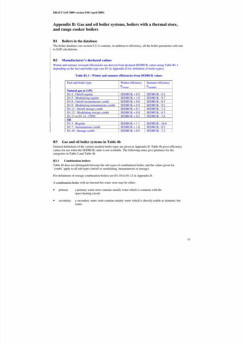
8/14/2019 Draft SAP 2009 Main Document
http://slidepdf.com/reader/full/draft-sap-2009-main-document 38/91
DRAFT SAP 2009 version 9.90 (April 2009)
37
Appendix B: Gas and oil boiler systems, boilers with a thermal store,
and range cooker boilers
B1 Boilers in the database
The boiler database (see section 9.2.1) contains, in addition to efficiency, all the boiler parameters relevantto SAP calculations.
B2 Manufacturer’s declared values
Winter and summer seasonal efficiencies are derived from declared SEDBUK values using Table B1.1
depending on the fuel and boiler type (see D1 in Appendix D for definition of boiler types).
Table B1.1 : Winter and summer efficiencies from SEDBUK values
Fuel and boiler type Winter efficiency
Ewinter
Summer efficiency
Esummer
Natural gas or LPG D1.4 : On/off regular SEDBUK + 0.9 SEDBUK - 9.2
D1.5 : Modulating regular SEDBUK + 1.0 SEDBUK - 9.7
D1.8 : On/off instantaneous combi SEDBUK + 0.8 SEDBUK - 8.5
D1.9 : Modulating instantaneous combi SEDBUK + 0.9 SEDBUK - 9.2
D1.11 : On/off storage combi SEDBUK + 0.7 SEDBUK - 7.2
D1.12 : Modulating storage combi SEDBUK + 0.8 SEDBUK - 8.3
D1.13 or D1.14 : CPSU SEDBUK + 0.2 SEDBUK - 1.6
Oil
D1.3 : Regular SEDBUK + 1.1 SEDBUK - 10.6
D1.7 : Instantaneous combi SEDBUK + 1.0 SEDBUK - 8.5
D1.10 : Storage combi SEDBUK + 0.9 SEDBUK - 7.2
B3 Gas and oil boiler systems in Table 4b
General definitions of the various modern boiler types are given in Appendix D. Table 4b gives efficiency
values for use when the SEDBUK value is not available. The following notes give guidance for the
categories in Table 2 and Table 4b.
B3.1 Combination boilers
Table 4b does not distinguish between the sub-types of combination boiler, and the values given for
‘combi’ apply to all sub-types (on/off or modulating, instantaneous or storage).
For definitions of storage combination boilers see D1.10 to D1.12 in Appendix D.
A combination boiler with an internal hot water store may be either:
• primary a primary water store contains mainly water which is common with the
space heating circuit.
• secondary a secondary water store contains mainly water which is directly usable as domestic hotwater.

8/14/2019 Draft SAP 2009 Main Document
http://slidepdf.com/reader/full/draft-sap-2009-main-document 39/91
DRAFT SAP 2009 version 9.90 (April 2009)
38
Primary storage combi boiler Secondary storage combi boiler
Figure B1 Primary and secondary storage combi boilers
The essential difference between a CPSU (see section B3.5) and a storage combination boiler with a larger
primary store is that in the case of a CPSU the feed to the space heating circuit is taken from the store,
while in the case of a storage combi with a larger primary store, the store does not feed the space heating
circuit.
B3.2 Boilers 1998 or later
If the ignition type is not known, a boiler with a fan-assisted flue may be assumed to have automatic
ignition, and one with an open flue to have a permanent pilot light.
B3.3 Boilers with fan-assisted flue
‘Low thermal capacity’ means a boiler either having a copper heat exchanger or having an internal water
content not exceeding 5 litres. If the position is uncertain the category of ‘high thermal capacity’ should be
used.
B3.4 Boiler selected by date
The date refers to the year of manufacture of the boiler. If this is uncertain the older category should beused.
B3.5 Combined Primary Storage Unit (CPSU)
A CPSU is defined in D 1.13. The store must be at least 70 litres - if the store is less than 70 litres, the
appliance should be treated as a storage combination boiler. A schematic illustration of a CPSU is shown in
Figure B2.
Note: If the store is a different appliance from the boiler (ie contained within a separate overall casing) the
system should be treated as a boiler with a thermal store as described in B4.
Fuel
Space
heating
loadHot
water
Figure B2 Combined primary storage unit (CPSU)
SpaceHeating
Load
Hot
Water
Fuel

8/14/2019 Draft SAP 2009 Main Document
http://slidepdf.com/reader/full/draft-sap-2009-main-document 40/91
DRAFT SAP 2009 version 9.90 (April 2009)
39
B4 Boilers with a thermal store
All systems described in this section have hot water stores as a separate appliance from the boiler.
B4.1 Integrated thermal store
An integrated thermal store is designed to store primary hot water, which can be used directly for space
heating and indirectly for domestic hot water. The heated primary water is circulated to the space heating(e.g. radiators). The domestic hot water is heated instantaneously by transferring the heat from the stored
primary water to the domestic hot water flowing through the heat exchanger. A schematic illustration of an
integrated thermal store is shown in Figure B3.
For an appliance to qualify as an integrated thermal store, the specification for integrated thermal stores∗
must be complied with, and at least 70 litres of the store volume must be available to act as a buffer to the
space heating demand. If the WMA specification is not met then the device should be treated like aconventional boiler and hot water cylinder. If only the volume requirement is not met, then the device may
be treated as a hot water only thermal store.
Space
heatingload
Fuel
Separate
boiler
Hotwater
Thermal store
Figure B3 Integrated thermal store
B4.2 Hot water only thermal store
A hot water only thermal store is designed to provide domestic hot water only and is heated by a boiler. Thedomestic hot water is heated by transferring the heat from the primary stored water to the domestic hot
water flowing through the heat exchanger, the space heating demand being met directly by the boiler. A
schematic illustration of a hot water only thermal store is shown in Figure B4.
For an appliance to qualify as a hot water only thermal store, the WMA specification for hot water only
thermal stores* must be complied with. If this requirement is not met then the device should be treated like aconventional boiler and hot water cylinder.
Space
heating
load
Fuel
Separate
boiler
Hot
water
Thermal store
Figure B4 Hot water only thermal store
∗ Performance Specification for Thermal Stores, 1999. Obtainable from the Hot Water Association
(www.hotwater.org.uk )

8/14/2019 Draft SAP 2009 Main Document
http://slidepdf.com/reader/full/draft-sap-2009-main-document 41/91
DRAFT SAP 2009 version 9.90 (April 2009)
40
B5 Range cookers
Range cookers are flued cooking appliances predominantly constructed of cast iron designed to provide
some heat from their case into the space in which they are located. There are three types.
B5.1 Range cooker with boiler for space heating
This type provide an independent water heating function for space heating in addition to the cookingfunction.. There are two design variations::
(i) Twin burner range cooker/boiler – an appliance with two independently controlled burners, one
for the cooking function, one for the water heating function for space heating, or for space and
water heating,
(ii) Single burner range cooker/boiler – an appliance with a single burner that provides a cooking
function and a water heating function for space heating, or for space and water heating
For the twin burner type, the efficiency can be can be from the boiler efficiency database, manufacturer's
declaration or Table 4b, as explained in section 9.2.2 of this document.
For the single burner type, the efficiency should be obtained from Table 4b.
B5.2 Single burner range cooker/water heater
This type provides a cooking function and some heating of domestic hot water.
B5.3 Single burner dry heat range cooker
This type is an appliance with a single burner that provides a cooking function. It is not included in SAP
calculations.

8/14/2019 Draft SAP 2009 Main Document
http://slidepdf.com/reader/full/draft-sap-2009-main-document 42/91
DRAFT SAP 2009 version 9.90 (April 2009)
41
Appendix C: Community heating, including schemes with Combined
Heat and Power (CHP) and schemes that recover heat from power
stations.
C1 Community heating where heat is produced by centralised unit by dedicatedplant
In community schemes, also known as group or district schemes, heat produced centrally serves a number
of dwellings or communal areas.
CHP (Combined heat and Power) is defined as the simultaneous generation of heat and power in a single
process.
There are two principal ways of producing heat for community heating by a dedicated plant (but see also
section C3):
- heat produced by boilers only (Figure C1);
- heat produced by a combination of boilers and CHP units (Figure C2).
Fuel Boilersonly
Siteload
Siteheat
Distribution Losses
Losses
heatSite
load
Siteheat load
Figure C1 Community heating with heat supplied by boilers only
Fuel
CHP
Boilers
Losses
Site heatload
Siteheat load
Electricity
Distribution LossesLosses
heat
heat
Figure C2 Community heating with heat supplied by a combination of boilers and CHP
For community heating with CHP Schemes, the CHP unit is the primary heat source, and back-up boilers of
conventional design are used when the heat output of the CHP plant is insufficient to meet the instantaneous
demand. The proportion of heat from CHP and from boilers varies from installation to installation.
The proportions of heat from the CHP and from conventional boilers, and the heat and electrical
efficiencies of the CHP for the calculation of CO2 emissions, should be estimated, either on the basis of
operational records or in the case of a new scheme on the basis of its design specification. Heat efficiency is
defined as the annual useful heat supplied from a CHP scheme divided by the total annual fuel input. The
power efficiency is the total annual power output divided by the total annual fuel input.

8/14/2019 Draft SAP 2009 Main Document
http://slidepdf.com/reader/full/draft-sap-2009-main-document 43/91
DRAFT SAP 2009 version 9.90 (April 2009)
42
The heat efficiency of the CHP should be based on the useful heat supplied by the CHP to the community
heating , excluding any dumped heat (see Figure C3).
Figure C3 An example of a heat profile chart
The heat required for space and water heating is calculated using an alternative worksheet, designed for
calculating SAP when space and water heating is provided by community heating (with or without CHP).
The heat price for community heating is taken from Table 12. This price incorporates bulk rates for buying
the fuel used in the plant, operating costs, energy used in pumping the hot water and, in the case of CHP,
receipts from the sale of the electricity generated. The factor in Table 4c(3) for controls and charging
method.
For the calculation of CO2 emissions, the efficiency to be used is that of the generating plant. A default
figure is given in Table 4a for community boilers but, if known, the actual efficiency of the boilers should
be used instead: see C2. For CHP plant, the efficiency can be specified as either (a) the heat efficiency and
the electrical efficiency, or (b) the overall efficiency and the heat-to-power ratio.
C2 Boiler efficiency
The efficiency of community boilers is assessed for SAP purposes in the same way as for domestic boilers.
The procedures described in Appendix D should be followed, including for boilers with rated output over
400 kW, except that the winter efficiency as calculated in D2.2 is used for all parts of the year (thus a
separate summer efficiency need not be calculated or declared).
Where boilers of different efficiency are used in combination the efficiency for SAP purposes is a weighted
average:
∑
∑
=
=
×
=n
1 j
j
n
1 j j j
average
R
ER
E
where
n is the number of boilers
R j is the rated output of boiler j
E j is the winter efficiency of boiler j calculated as set out in D2.2
0
100
200
300
400
500
600
700
800
J a n
F e b
M a r
A p r
M a y J u
n J u l
A u g
S e p
O c t
N o v
D e c
A v e r a g e M o n t h l y H e a t i n g D e m a n
d ( k W )
Boiler Heat Supplied
CHP Heat Dumped
CHP Heat Supplied

8/14/2019 Draft SAP 2009 Main Document
http://slidepdf.com/reader/full/draft-sap-2009-main-document 44/91
DRAFT SAP 2009 version 9.90 (April 2009)
43
C3 Heat distribution
C3.1 Distribution loss
Heat loss in the distribution network is allowed for by increasing the heat to be supplied by the community
heating scheme by a ‘distribution loss factor’. Where the linear heat density of the community heating
scheme as awhole is known to be 2 MWh/year/m or higher then the distribution loss factor is taken from Table 12c.
Note: the linear heat density is the heat delivered to premises from the distribution network in
MWh/year divided by the total length of the distribution network (“trench length”) in metres, and
should be obtained from the scheme manager.
Where the linear heat density is less than 2 MWh/year/m, or is not known, then a distribution loss factor forthe
community heating scheme should be determined. This should be requested from the scheme manager. If
the result is lower than the value in Table 12c then the value from Table 12c is to be used instead. If the
distribution loss factor cannot be calculated from scheme data then a value of 1.5 should be used.
Note: the distribution loss factor should be calculated by the scheme manager(or designer in the caseof a new scheme) using one of two methods:
(a) if the scheme has full heat metering at all connections to the distribution network, then the total
heat supplied to the network from the energy centre(s) divided by the sum of the heat delivered
from all the network connections (either to whole buildings or individual apartments), measured
over a one year period (the same period for both), or
(b) the formula
1 + linear loss × total length of pipework ÷ (total heat supplied × 114)
where:
‘linear loss’ is the average heat loss per metre run of pipework in W/m, calculated in
accordance with ISO 12241, equations (8) and (9);
‘total length of pipework’ is the length of the distribution system pipes for the whole
scheme in metres;
‘total heat supplied’ is the heat supplied from the energy centre(s) to the distribution
network over a whole year, in MWh/year;
114 converts MWh/year to W.
C3.2 Energy for pumpingCO2 emissions associated with the electricity used for pumping water through the distribution system are
allowed for by adding electrical energy equal to 1% of the energy required for space and water heating.
C4 Community heating schemes that recover waste heat from power stations
This includes waste heat from power stations rated at more than 10 MW electrical output and with a power
efficiency greater than 35%. (Otherwise the system should be considered as CHP.)
For community schemes that recover heat from power stations, the waste heat is the primary heat source,
and secondary boilers of conventional design are used when the available waste heat is insufficient to meet
the instantaneous demand. The proportions of heat from the power station and from the conventional boilers
should be estimated, either on the basis of operational records or in the case of a new scheme on the basis of its design specification.

8/14/2019 Draft SAP 2009 Main Document
http://slidepdf.com/reader/full/draft-sap-2009-main-document 45/91
DRAFT SAP 2009 version 9.90 (April 2009)
44
The CO2 emissions are calculated using the following procedure:
a) use the procedure for calculating community heating with CHP or schemes that recover heat from
power stations;b) boxes (101*) to (106*) are zero;
c) the emission factor for waste heat from power stations (Table 12) applies in box (107*) and the
calculation is then completed as normal.
The fraction of heat in box (83*) is the fraction of useful heat, i.e.
outputboilerheatwaste
heatwaste
+
Note: The applicable emission factor in Table 12 reflects emissions associated with the electricity used for
pumping the water from the power station.
C5 Permutations of heat generators
Possible systems for community heating schemes include:
1. A single boiler or set of boilers all using the same fuel. In the case of a set of boilers the averageseasonal efficiency for the boilers is used for the calculation (see C2).
2. Two boilers or two sets of boilers, using two different fuels such as mains gas and biomass. In this case
the total heat requirement is divided between the two boilers or sets of boilers according to the design
specification of the overall system. Different average seasonal efficiencies apply to the two sets of boilers and the CO2 emissions are calculated using the emission factors of the respective fuels.
The calculation proceeds as for a community scheme without CHP, i.e. worksheet sections 9b, 10b,
11b and 12a.
Use (83*) for the fraction of heat from boiler type 2 and (84*) for the fraction of heat from boiler
type 1. Similarly (86a*) to (87b*) are used for the two boiler types. For CO2 emissions and primaryenergy, (104) to (106) are used twice, multiplying each (104) and (105) by the applicable fraction of
heat.
3. CHP plant and boiler(s), calculations according to section C1.
If there are two boilers or two sets of boilers using two different fuels (in addition to the CHP plant) the
heat requirement from boilers is divided between the two boilers or sets of boilers according to the
design specification of the overall system. Different average seasonal efficiencies apply to the two sets
of boilers and the CO2 emissions are calculated using the emission factors of the respective fuels.
Use (86a*) and (87b*) twice, for the two boiler types, multiplying by the applicable fraction of heat.For CO2 emissions and primary energy, (109*), (110*) and (113*) are used twice, multiplying each
(110*) and (113*) by the applicable fraction of heat.
4. Utilisation of waste heat from a power station topped up by boilers, calculations according to
section C4.
5. Geothermal heat topped up by boilers. The calculation is the same as that described in C4 for waste
heat from power stations.
6. An electrically driven heat pump with various possibilities as to heat source, such as the ground or
waste heat from an industrial process. The calculation is essentially the same as that for boiler systems,
with the seasonal performance factor (SPF) for the heat pump system being used in place of boiler
efficiency. The SPF should take account of winter and summer operations as appropriate and of the
temperature of the heat source.

8/14/2019 Draft SAP 2009 Main Document
http://slidepdf.com/reader/full/draft-sap-2009-main-document 46/91
DRAFT SAP 2009 version 9.90 (April 2009)
45
C6 Community scheme providing DHW only
Some community schemes provide DHW only, with the space heating provided by heaters in each
dwelling.
In this case the specification and calculation of space heating is the same as for a dwelling not connected to
a community scheme. This includes a main heating system and secondary heaters.
A DHW-only community scheme can be:
- from community boilers;
- from a community heat pump;
- from a community CHP
Data required are:
- fuel used by community scheme (same fuel options as for community scheme providing space and water
heating)
- efficiency of community boilers, heat pump or CHP
- if CHP, the heat-to-power ratio
- heat distribution characteristics for the distribution loss factor (Table 12c)
- whether a hot water cylinder is in the dwelling and if so its volume plus either its measured loss factor or
its insulation type and insulation thickness.
The water heating calculation follows that for a full community scheme including, if there is not a cylinder
in the dwelling, assigning for the purposes of the calculation a 110 litre cylinder with 50 mm factory-
applied insulation. The control factor, Table 4c 3), is not applicable and 1.0 should be used for water
heating (but allowing for the distribution loss factor from Table 12c). Include one-half of the normal
community standing charge in the calculation of fuel costs unless the space heating is also a community
system (see next paragraph).
This also allows for the case where the community system is different for space heating and for water
heating. Separate community heating parameters apply to each system including heat distribution
characteristics. In this case the total standing charge is the normal community standing charge.
C7 Community biomass CHP
For community heating with CHP, it is possible for the total CO2 emissions calculated at (114*), or at
(106b) in the case of a DHW-only community scheme, to be negative. In such cases the negative value is
replaced by zero. The reason is that, once this quantity becomes negative, it becomes advantageous to
increase the heating requirements of the dwellings, e.g. by removing insulation.
However, in the case of a CHP plant fuelled by biomass, the residual negative amount is carried forward for
possible use in consideration of zero carbon homes (see section 15 of the SAP specification). In this way
the full benefit of biomass CHP can be taken into account. This is permissible only when:
(a) the DER is less than or equal to 0; and
(b) the Heat Loss Parameter (HLP) does not exceed 0.8 W/m²K, thus ensuring that a high standard of insulation is provided; and
(c) the community CHP is fuelled by biomass, not a fossil fuel.
If all these conditions are not met the residual is set to 0.

8/14/2019 Draft SAP 2009 Main Document
http://slidepdf.com/reader/full/draft-sap-2009-main-document 47/91
DRAFT SAP 2009 version 9.90 (April 2009)
46
Appendix D: Method of determining seasonal efficiency values for gas
and oil boilers
Note: The data and equations in this appendix are for manufacturers to calculate seasonal efficiency for
declaration purposes. They are not to be used by SAP assessors.
This appendix sets out, in D2 and D4, the method to be used by manufacturers to determine seasonal
efficiency for particular gas and oil boilers when test data have been obtained to establish conformity with
Council Directive 92/42/EEC*. This Directive has been implemented in the UK by the Boiler (Efficiency)
Regulations**.
Manufacturers’ declarations of seasonal efficiency values so calculated should be accompanied by the form
of words in D3, and SAP assessors should look for the same form of words in order to ascertain that the
efficiency value referred to is appropriate for SAP calculations.
Range cooker boilers with twin burners are covered by D5 and D6.
D1 Definitions
D1.1 Boiler
A gas or liquid fuelled appliance designed to provide hot water for space heating. It may (but need not) be
designed to provide domestic hot water as well.
D1.2 Condensing boiler
A boiler designed to make use of the latent heat released by the condensation of water vapour in the
combustion flue products. The boiler must allow the condensate to leave the heat exchanger in liquid form
by way of a condensate drain. ‘Condensing’ may only be applied to the definitions D1.3 to D1.14 inclusive.
Boilers not so designed, or without the means to remove the condensate in liquid form, are called ‘non-condensing’.
D1.3 Regular boiler
A boiler which does not have the capability to provide domestic hot water directly (ie not a combination
boiler). It may nevertheless provide domestic hot water indirectly via a separate hot water storage cylinder.
D1.4 On/off regular boiler
A regular boiler without the capability to vary the fuel burning rate whilst maintaining continuous burnerfiring. This includes those with alternative burning rates set once only at time of installation, referred to as
range rating.
D1.5 Modulating regular boiler
A regular boiler with the capability to vary the fuel burning rate whilst maintaining continuous burner
firing.
D1.6 Combination boiler
A boiler with the capability to provide domestic hot water directly, in some cases containing an internal hot
water store.
D1.7 Instantaneous combination boiler
A combination boiler without an internal hot water store, or with an internal hot water store of capacity less
than 15 litres.
*Council Directive 92/42/EEC on efficiency requirements for new hot-water boilers fired with liquid or
gaseous fuels. Official Journal of the European Communities No L/167/17. 21 May 1992, p. 92
**The Boiler (Efficiency) Regulations 1993, SI (1993) No 3083, as amended by the Boiler (Efficiency)
(Amendment) Regulations 1994, SI (1994) No 3083.

8/14/2019 Draft SAP 2009 Main Document
http://slidepdf.com/reader/full/draft-sap-2009-main-document 48/91
DRAFT SAP 2009 version 9.90 (April 2009)
47
D1.8 On/off instantaneous combination boiler
An instantaneous combination boiler that only has a single fuel burning rate for space heating. This includes
appliances with alternative burning rates set once only at time of installation, referred to as range rating.
D1.9 Modulating instantaneous combination boiler
An instantaneous combination boiler with the capability to vary the fuel burning rate whilst maintaining
continuous burner firing.
D1.10 Storage combination boiler
A combination boiler with an internal hot water store of capacity at least 15 litres but less than 70 litres
ORa combination boiler with an internal hot water store of capacity at least 70 litres, in which the feed to the
space heating circuit is not taken directly from the store. If the store is at least 70 litres and the feed to the
space heating circuit is taken directly from the store, treat as a CPSU (D1.13 or D1.14)
OR
a combination boiler with an external store.
D1.11 On/off storage combination boiler
A storage combination boiler that only has a single fuel burning rate for space heating. This includesappliances with alternative burning rates set once only at time of installation, referred to as range rating.
D1.12 Modulating storage combination boiler
A storage combination boiler with the capability to vary the fuel burning rate whilst maintaining continuous
burner firing.
D1.13 On/off combined primary storage unit (CPSU)
A single appliance designed to provide both space heating and the production of domestic hot water, in
which there is a burner that heats a thermal store which contains mainly primary water which is in common
with the space heating circuit. The store must have a capacity of at least 70 litres and the feed to the space
heating circuit must be taken directly from the store. The appliance does not have the capability to vary the
fuel burning rate whilst maintaining continuous burner firing. This includes those with alternative burningrates set once only at time of installation, referred to as range rating.
D1.14 Modulating combined primary storage unit (CPSU)
A single appliance designed to provide both space heating and the production of domestic hot water, in
which there is a burner that heats a thermal store which contains mainly primary water which is in common
with the space heating circuit. The store must have a capacity of at least 70 litres and the feed to the space
heating circuit must be taken directly from the store. The appliance has the capability to vary the fuel
burning rate whilst maintaining continuous burner firing.
D1.15 Low temperature boiler
A non-condensing boiler designed as a low temperature boiler and tested as a low temperature boiler as
prescribed by the Boiler Efficiency Directive (ie; the part load test was carried out at average boiler
temperature of 40°C).
D1.16 Keep-hot facility
A facility within an instantaneous combination boiler whereby water within the boiler may be kept hot
while there is no demand. The water is kept hot either (i) solely by burning fuel, or (ii) by electricity, or (iii)
both by burning fuel and by electricity, though not necessarily simultaneously.
D2 Method for calculating Seasonal Efficiencies
The method of calculation is applicable only to boilers for which the full load and the 30% part loadefficiency values, obtained by the methods deemed to satisfy Council Directive 92/42/EEC, are available.
These are net efficiency values. It is essential that both test results are available and that the tests are
appropriate to the type of boiler as defined in the Council Directive, otherwise the calculation cannot
proceed.

8/14/2019 Draft SAP 2009 Main Document
http://slidepdf.com/reader/full/draft-sap-2009-main-document 49/91
DRAFT SAP 2009 version 9.90 (April 2009)
48
The efficiencies calculated by this procedure are:
a) SEDBUK (Seasonal Efficiency of Domestic Boilers in the UK). This is used as a general indicator of efficiency; it is no longer used for SAP calculations.
b) Winter and summer seasonal efficiencies for SAP calculations. The winter seasonal efficiency is used
for space heating, the summer efficiency applies to DHW heating in summer, and DHW heating in
winter is a combination of both.
In the calculation method the data are first converted to gross efficiency under test conditions, and thenconverted to a seasonal efficiency value that applies under typical conditions of use in a dwelling, allowing
for standing losses.
In this Appendix, efficiencies are expressed in percent. Intermediate calculations should be done to at least
four places of decimals of a percentage, and the final result rounded to one decimal place.
D2.1 SEDBUK
The procedure is as follows:
1. Determine fuel for boiler typeThe fuel for boiler type must be one of natural gas, LPG (butane or propane), or oil (kerosene, gas oil or
FAME). SEDBUK cannot be calculated for other fuels.
2. Obtain test data
Retrieve the full-load net efficiency and 30% part-load net efficiency test results. Tests must have been
carried out using the same fuel as the fuel for boiler type, except as provided in D4.
3. Apply correction to high test results
Apply an adjustment to full-load efficiency greater than 95.5% net and to part-load efficiency greater than
96.6% net to correct for observed bias in test results, according to Table D2.1.
Table D2.1 : Efficiency correction term
Full-load efficiency( EFL) 30% Part-load efficiency (EPL)
Correction if
EFL > 95.5%
Correction if
EFL ≤ 95.5%
Correction if
EPL > 96.6%
Correction if
EPL ≤ 96.6%
- 0.673 (EFL – 95.5) 0 - 0.213 (EPL – 96.6) 0
4. Reduce to maximum net efficiency values
Table D2.2 gives the maximum values of net efficiency for each fuel that may be used. Reduce any greater
value (after adjustment according to Table D2.1) to the appropriate value given in Table D2.2.
Table D2.2 : Maximum net efficiency values (in %)
Condensing boilers Non-condensing boilersNatural gas LPG Oil Gas (incl. LPG) Oil
Full-load 98 98 98 92 92
Part-load 108 106 104 91 93
5. Convert the full and 30% part load efficiencies from net values to gross. Use the following equation with the appropriate factor from Table D2.3.
Egross = f × Enet
Table D2.3 : Efficiency conversion factors
Fuel Net-to-gross conversion factor, f
Natural gas 0.901LPG (propane or butane) 0.921
Oil (kerosene or gas oil) 0.937
8/14/2019 Draft SAP 2009 Main Document
http://slidepdf.com/reader/full/draft-sap-2009-main-document 50/91
DRAFT SAP 2009 version 9.90 (April 2009)
49
Biodiesel 0.937
6. Categorise the boiler
a) Select the appropriate category for the boiler according to the definitions given in D1.
b) If a gas or LPG boiler, determine whether it has a permanent pilot light:if it has a permanent pilot light, set p = 1
if not, set p = 0.
c) In the case of a storage combination boiler (either on/off or modulating) determine from the test report
whether the losses from the store were included in the values reported (this depends on whether thestore was connected to the boiler during the tests):
if the store loss is included, set b = 1
if not, set b = 0.
d) In the case of a storage combination boiler or a CPSU, obtain the store volume, Vcs, in litres from the
specification of the device and the standby loss factor, L, using the following equation:
if t < 10 mm: L = 0.0945 – 0.0055tif t ≥ 10 mm: L = 0.394/twhere t is the thickness of the insulation of the store in mm.
7. Calculate seasonal efficiency a) Use the boiler category and other characteristics as defined in D1 (non-condensing or condensing; gas
or LPG or oil; on/off or modulating) to look up the appropriate SEDBUK equation number in Table
D2.4. If no equation number is given the calculation cannot proceed. Otherwise, select the appropriate
equation from Table D2.5 or Table D2.6.
b) Substitute the gross full and part load efficiencies (found in step 5) and p, b, V and L (found in step 6).
Round the result to one decimal place; i.e. to nearest 0.1%. Note the result as [x] for the purpose of the
declaration in D3.

8/14/2019 Draft SAP 2009 Main Document
http://slidepdf.com/reader/full/draft-sap-2009-main-document 51/91
DRAFT SAP 2009 version 9.90 (April 2009)
50
Table D2.4 : Boiler category table
non-condensing (see D1.2) condensing (see D1.2)
Gas or LPG Oil l o w
- t e m p e r a t u r e
( s e e D 1 . 1
5 )
Gas or LPG Oil
SEDBUK Equation numbers
for different boiler types
o n / o f f
( s e e D 1 . 4 ,
D 1 . 8 ,
D 1 . 1
1 ,
D 1 . 1
3 )
m o d u l a t i n g
( s e e D 1 . 5 ,
D 1 . 9 ,
D 1 . 1
2 ,
D 1 . 1
4 )
o n / o f f
( s e e D 1 . 4 ,
D 1 . 8 ,
D 1 . 1
1 )
m o d u l a t i n g
( s e e D 1 . 5 ,
D 1 . 9 ,
D 1 . 1
2 )
o n / o f f
( s e e D 1 . 4 ,
D 1 . 8 ,
D 1 . 1
1 ,
D 1 . 1
3 )
m o d u l a t i n g
( s e e D 1 . 5 ,
D 1 . 9 ,
D 1 . 1
2 ,
D 1 . 1
4 )
o n / o f f
( s e e D 1 . 4 ,
D 1 . 8 ,
D 1 . 1
1 )
m o d u l a t i n g
( s e e D 1 . 5 ,
D 1 . 9 ,
D 1 . 1
2 )
regular boiler
(see D1.4, D1.5)101 102 201 X X 101 102 201 X
instantaneous combi boiler
(see D1.7, D1.8, D1.9)103 104 202 X X 103 104 202 X
storage combi boiler
(see D1.10, D1.11, D1.12)105 106 203 X X 105 106 203 X
combined primary storage unit
(see D1.13, D1.14)107 107 X X X 107 107 X X
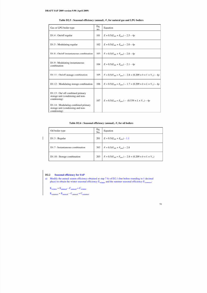
8/14/2019 Draft SAP 2009 Main Document
http://slidepdf.com/reader/full/draft-sap-2009-main-document 52/91
DRAFT SAP 2009 version 9.90 (April 2009)
51
Table D2.5 : Seasonal efficiency (annual), E, for natural gas and LPG boilers
Gas or LPG boiler typeEq.
no.Equation
D1.4 : On/off regular 101 E = 0.5( E full + E part) – 2.5 – 4 p
D1.5 : Modulating regular 102 E = 0.5( E full + E part) – 2.0 – 4 p
D1.8 : On/off instantaneous combination 103 E = 0.5( E full + E part) – 2.8 – 4 p
D1.9 : Modulating instantaneouscombination
104 E = 0.5( E full + E part) – 2.1 – 4 p
D1.11 : On/off storage combination 105 E = 0.5( E full + E part ) – 2.8 + (0.209 × b × L × V cs) – 4 p
D1.12 : Modulating storage combination 106 E = 0.5( E full + E part ) – 1.7 + (0.209 × b × L × V cs) – 4 p
D1.13 : On/ off combined primarystorage unit (condensing and non-
condensing)
D1.14 : Modulating combined primary
storage unit (condensing and non-
condensing)
107 E = 0.5( E full + E part ) – (0.539 × L × V cs) – 4 p
Table D2.6 : Seasonal efficiency (annual), E, for oil boilers
Oil boiler typeEq.
No.Equation
D1.3 : Regular 201 E = 0.5( E full + E part) - 1.1
D1.7 : Instantaneous combination 202 E = 0.5( E full + E part) – 2.8
D1.10 : Storage combination 203 E = 0.5( E full + E part ) – 2.8 + (0.209 × b × L × V cs)
D2.2 Seasonal efficiency for SAP
a) Modify the annual season efficiency obtained at step 7 b) of D2.1 (but before rounding to 1 decimal
place) to obtain the winter seasonal efficiency Ewinter and the summer seasonal efficiency Esummer:
Ewinter = Eannual – Cannual + Cwinter
Esummer = Eannual – Cannual + Csummer

8/14/2019 Draft SAP 2009 Main Document
http://slidepdf.com/reader/full/draft-sap-2009-main-document 53/91
DRAFT SAP 2009 version 9.90 (April 2009)
52
where Cannual, Cwinter, and Csummer are given in Table D2.7 according to fuel and boiler type.
b) Round the results to one decimal place, i.e. to nearest 0.1%.
Table D2.7 : Annual and seasonal coefficients
Fuel and boiler type Equation number
(Table D2.4)
Annual offset
Cannual
Winter offset
Cwinter
Summer offset
Csummer
Natural gas or LPG
D1.4 : On/off regular 101 -2.5 -1.6 -11.7
D1.5 : Modulating regular 102 -2.0 -1.0 -11.7
D1.8 : On/off instantaneous combi 103 -2.8 -2.0 -11.3
D1.9 : Modulating instantaneous combi 104 -2.1 -1.2 -11.3
D1.11 : On/off storage combi 105 -2.8 -2.1 -10.0
D1.12 : Modulating storage combi 106 -1.7 -0.9 -10.0
D1.13 or D1.14 : CPSU 107 -0.761 -0.545 -2.4
Oil
D1.3 : Regular 201 -1.1 0.0 -11.7D1.7 : Instantaneous combi 202 -2.8 -1.8 -11.3
D1.10 : Storage combi 203 -2.8 -1.9 -10.0
D3 Declaring values of seasonal efficiency
Manufacturers wishing to declare their products' seasonal efficiencies for the specific purposes of
calculating SAP ratings can do so provided that:
a) they use the SEDBUK calculation procedure given in D2.1 above; and
b) the necessary boiler test data and the calculations are certified by a Notified Body accredited for the
testing of boilers by an EU national accreditation service. The Notified Body must certify that: ‘the full load
and part load efficiency test results detailed in [insert reference to report on the efficiency tests] have been
obtained by methods deemed to satisfy the Boiler Efficiency Directive’.
Where a manufacturer declares the SEDBUK, it shall be expressed as:
“Seasonal Efficiency (SEDBUK) = [x]%
The value is used in the UK Government’s Standard AssessmentProcedure (SAP) for energy rating of dwellings. The test data from
which it has been calculated have been certified by [insert name and/or
identification of Notified Body].”
Data for several products may be presented in tabulated form, in which case the second paragraph of thedeclaration should be incorporated as a note to the table.
D4 Method for calculating seasonal efficiency for boilers fuelled by LPG but
tested with natural gas
If the fuel for boiler type is LPG but the fuel used to obtain efficiency test results is natural gas then
seasonal efficiency may be calculated subject to certain conditions using the procedure given below. The
seasonal efficiency will be lower than if the fuel used to obtain the test results had been LPG.
1. Note the restrictions set out at the start of D2, which still apply.

8/14/2019 Draft SAP 2009 Main Document
http://slidepdf.com/reader/full/draft-sap-2009-main-document 54/91
DRAFT SAP 2009 version 9.90 (April 2009)
53
2. Any differences between the boiler fuelled by natural gas (used to obtain full-load and 30% part-load
efficiency test results) and the boiler fuelled by LPG (for which seasonal efficiency is required) must be
minor. Examples of minor differences are a change of gas injector or adjustment by a single screw on thegas valve.
3. Determine the net heat input on a net calorific value basis for both the natural gas boiler and the LPG
boiler. The LPG figure must lie within ± 5% of the natural gas figure.
4. Determine by measurement the percentage dry CO2 by volume at the maximum heat input for both thenatural gas boiler and the LPG boiler. From the results calculate the excess air fractions for both boilers.
The calculated excess air fraction for the LPG boiler must not exceed that for the natural gas boiler by more
than 5% (of the natural gas excess air fraction).
5. Retrieve the full-load net efficiency and 30% part-load net efficiency test results.
6. Apply correction to high test results as in step 3 of D.2.1.
7. If the boiler is a condensing boiler then deduct 2.2 percentage points from the 30% part-load net
efficiency test result.
8. Follow the calculation procedure in D2.1 from step 4 onwards and in D2.2, taking the fuel for boiler typeas LPG.
D5 Method for calculating Seasonal Efficiency and Case Emission value of a twin-
burner range cooker boiler
1. The method of calculation of the Seasonal Efficiency is applicable only to cooker boilers for which the
full load and the 30% part load efficiency values for the boiler function, obtained by the methods
deemed to satisfy Council Directive 92/42/EEC, are available.
Note: A range cooker boiler which does not have the capability to provide domestic hot water
directly (i.e. is not a combination boiler), but which may nevertheless provide domestic hot water indirectly via a separate hot water storage cylinder exactly matches the definition D1.3 for a Regular
Boiler. Consequently the methods deemed to satisfy 92/42/EEC for a Regular Boiler will equally
satisfy this requirement for the equivalent type of range cooker boiler.
These efficiencies are for the heat transferred to water and are carried out with the cooker burner turned
off.
When undertaking the efficiency test, record
- input power (net) at full load conditions,Φinput,net, in kW.
- heat transfer to the water under full load conditions,Φwater, in kW
- flue loss (net) under full load conditions,Φflue,net , in kW according to the method given in
EN 304:1992 + Amendment 1: 1998 or other method assured by the independent test laboratory as
providing comparable results for the product under test. Note: Independent test laboratory is qualified in D6 b).
2. Calculate the seasonal efficiencies according to D2 using the appropriate equation for a regular boiler.
3. Calculate the case heat emission at full load from
Φcase = Φinput,net – Φwater -Φflue,net
where Φwater is the heat transferred to water under full load conditions;
Φflue,net is the flue gas loss measured according to BS EN 304.
4. If Φcase < 0.2 kW and the case temperatures of the range cooker are below 80°C, the case emission
may, as an alternative, be derived from measurements of the case temperatures according toSupplement 1 to OFTEC Standard OFS A101, subject to a maximum figure of Φcase = 0.2 kW.

8/14/2019 Draft SAP 2009 Main Document
http://slidepdf.com/reader/full/draft-sap-2009-main-document 55/91
DRAFT SAP 2009 version 9.90 (April 2009)
54
Note: Supplement 1 to OFTEC Standard OFS A101 (applicable for oil and gas) can be obtained from
OFTEC (Oil Firing Technical Association), Tel 0845 6585080, Fax 0845 6585181, e-mail
5. If Φcase exceeds either of 0.05 ×Φwater or 1 kW, reduce Φcase to 0.05 × Φwater or 1 kW (whichever is the
smaller).
6. Provide the values of Φcase and Φwater in kW as part of the test report.
D6 Declaring values of seasonal efficiency and heat emission from the case for
twin-burner range cooker boilers
Manufacturers wishing to declare their products’ seasonal efficiencies and case emission values for the
specific purposes of calculating SAP ratings can do so provided that:
a) They use the calculation procedure given in D5 above; and
b) The necessary boiler test data and calculations are certified by an independent Test Laboratory notified
under the Council Directive 92/42/EEC on efficiency requirements for new hot-water boilers fired withliquid or gaseous fuels (known as a “Notified Body”).
Where a manufacturer declares the seasonal efficiency and the case emission value, it shall be expressed as:
Seasonal Efficiency (SEDBUK) = [x]%
Case heat emission at full load = [y] kW
Heat transfer to water at full load = [z] kW
The values are used in the UK Government’s Standard Assessment
Procedure (SAP) for the energy rating of dwellings. The test data from
which they have been calculated has been certified by [insert name and/or
identification of Notified Body].
Data for several products may be presented in tabulated form, in which case the last paragraph of the
declaration should be incorporated as a note to the table.

8/14/2019 Draft SAP 2009 Main Document
http://slidepdf.com/reader/full/draft-sap-2009-main-document 56/91
DRAFT SAP 2009 version 9.90 (April 2009)
55
Appendix E: Method of determining seasonal efficiency for gas, oil and
solid fuel room heaters
Note: The data and equations in this appendix are for manufacturers to calculate seasonal efficiency for
declaration purposes. They are not to be used by SAP assessors.
This appendix sets out the method to be used to determine the seasonal efficiency for gas, oil and solid fuel
room heaters.
E1 Efficiency determination
Only test results obtained by one of the recognised methods given in Table E1, Table E2 and Table E3 may
be used to establish a seasonal efficiency for SAP calculations. The methods give comparable results.
Table E1 : Recognised efficiency test methods for gas room heaters
Reference Title Applies to (code in
Table 4a or 4b)
BS EN 613:2001 Independent gas-fired convection heaters 609
BS EN 13278:2003 Open-fronted gas-fired independent space heaters 607
BS EN 1266:2002 Independent gas-fired convection heaters incorporating a fan to
assist transportation of combustion air and/or flue gases
610
BS 7977-1:2002 Specification for safety and rational use of energy of gas
domestic appliances. Part 1: Radiant/Convectors
603, 604, 605, 606
BS 7977-2:2003 Specification for safety and rational use of energy of gas
domestic appliances. Part 2: Combined appliances: Gas
fire/back boiler
109
Table E2 : Recognised efficiency test method for oil room heaters
Reference Title Applies to (code in
Table 4a or 4b)
OFS A102:1999 Oil fired room heaters with atomising or vaporising burners
with or without boilers, heat output up to 25 kW
131, 132, 621, 622,
623, 624
Table E3 : Recognised efficiency test methods for solid fuel room heaters
Reference Title Applies to (code in
Table 4a)
BS EN 13229:2001 Inset appliances including open fires fired by solid fuels –
Requirements and test methods
156, 631, 632
BS EN 13240:2001 Roomheaters fired by solid fuel - Requirements and test
methods
158, 633, 634
BS EN 14785:2006 Residential space heating appliances fired by wood pellets –
Requirements and test methods
159, 635, 636

8/14/2019 Draft SAP 2009 Main Document
http://slidepdf.com/reader/full/draft-sap-2009-main-document 57/91
DRAFT SAP 2009 version 9.90 (April 2009)
56
Efficiency test results are normally calculated using the net calorific value of fuel. Before a declaration can
be made, conversion to gross must be carried out by multiplying the efficiency by the appropriateconversion factor given in Table E4.
Table E4: Efficiency conversion factors
Fuel Net-to-gross conversion factor
Natural gas 0.901
LPG (propane or butane) 0.921
Oil (kerosene or gas oil) 0.937
Biodiesel 0.937
House coal 0.97
Anthracite 0.98
Manufactured smokeless fuel 0.98
Wood logs 0.91
Wood chips 0.91
Wood pellets 0.91
E2 Declaring the efficiency of gas, oil and solid fuel room heaters
Manufacturers’ declarations so calculated should be accompanied by the following form of words:
"The net efficiency of this appliance has been measured as specified in
[insert appropriate entry from Table E1, Table E2 or Table E3] and the
result after conversion to gross using the appropriate factor from Table E4 of
SAP 2009 is [x]%. The test data has been certified by [insert name and/or
identification of Notified Body]. The gross efficiency value may be used in
the UK Government's Standard Assessment Procedure (SAP) for energy
rating of dwellings."

8/14/2019 Draft SAP 2009 Main Document
http://slidepdf.com/reader/full/draft-sap-2009-main-document 58/91
DRAFT SAP 2009 version 9.90 (April 2009)
57
Appendix F: Electric CPSUs
An electric CPSU is a central heating system providing space and domestic water heating. Primary water
heated mainly during off-peak times to up to 95°C in winter is stored in a thermal store. If the CPSUvolume is less than 270 litres, the on-peak fraction can become high leading to a poor SAP rating.
The procedure in this appendix applies for a 10-hour off-peak tariff providing 3 off-peak periods per day. It
is not valid for other tariffs.
The space heating circuit operates in the same way as a wet central heating system, with controls
appropriate for "wet" systems. For domestic hot water, secondary water flows directly from the cold mains
into a heat exchanger, where it is heated by the hot water in the store before being delivered to the taps.
In the case of an electric CPSU, the on-peak fraction should be calculated (because the procedure is basedon a fixed volume).
Note: The treatment of on-peak fraction is different from electric storage heating, because in the case of
storage heating the on-peak fraction is fixed (it is achieved by sizing the storage heaters).
The heat losses from the CPSU are calculated, as for other hot water storage vessels, in Section 4 of thecalculation, using data from Table 2 or Table 2b.
F1 Procedure for electric CPSUs:
The procedure below applies to the worksheet from box (82) onwards.
1. Calculate the on-peak fraction (for each month) using the following methodology:
a) Calculate minimum external temperature for which the stored heat can satisfy the demandtemperature
[ ] [ ]
m
mmmmaxmmmin
)37(
)78()n24()d39(1000C)76()37(T
−×÷×+−×= (F1)
nm is the number of days in the month. Cmax is off-peak heat available irrespective of power rating
of the heating element, calculated using the formula:
Cmax = 0.1456 × Vcs × (Tw – 48) (F2)
where Vcs is the CPSU capacity in litres and Tw is winter operating temperature in °C.
b) Calculate on-peak energy required
if Tmin – Te = 0, mmpeak on n)37(024.0E ××=−
otherwise( )
( ))TT(exp1
TTn)37(024.0E
emin
eminmmpeak on
−−−
−×××=− (F3)
2. Calculate the on-peak fraction
mm
peak on
)d39()81(
EF
+=
−(F4)
3. Apply the on-peak price to fraction F of the heating requirement (both space and water) and the off-peak
price to fraction (1 – F).
4. Enter 130 in box (87a)/

8/14/2019 Draft SAP 2009 Main Document
http://slidepdf.com/reader/full/draft-sap-2009-main-document 59/91
DRAFT SAP 2009 version 9.90 (April 2009)
58
Appendix G: Heat pumps
NOTE: This appendix will be revised to allow for tested data on heat pumps to be used.
A heat pump is a device which takes heat energy from a low temperature source and upgrades it to a higher
temperature at which it can be usefully employed for heating. There are a number of heat pump techniques
by which this can be achieved. The ratio of heat energy released to the energy consumed can besubstantially greater than one. Heat pump systems operate most efficiently when the source temperature is
as high as possible and the heat distribution temperature is as low as possible.
Heat pump systems are categorised by the low temperature heat source used (e.g. air, water, ground) and
the seasonal performance factors (SPF) given in Table 4a under "Efficiency" are assumed to apply for allsystems using that source. This is a simplified approach especially for ground source heat pumps where
energy may be collected from the ground in a variety of ways, e.g. using surface water from lakes or ponds,
using ground water from wells, using fluid (either refrigerant or a water/antifreeze mixture) circulated in
closed pipe loops buried horizontally in shallow trenches or vertically in boreholes.
At the time of publication, the SPF to be used for SAP calculations is the appropriate entry in Table 4a. Asystem of appliance-specific performance factors may be introduced (see Appendix Q).
Heat pumps can also be used in community schemes. That does not affect the calculation of the SAP rating
but the SPF of the heat pump should be used in box (104) for the calculation of CO2 emissions.
G1 Domestic hot water (DHW)
G1.1 DHW heated by heat pump with immersion heater
The heat pump raises the water temperature to a maximum of about 40°C, and an immersion heater is then
used to raise the water temperature to the required delivery temperature. For the purpose of the SAPcalculation it is assumed that 50% of domestic hot water heating is by the heat pump and 50% by the
immersion heater.
The average efficiency for water heating, box (86), is:
[ ] 5.0SPF50
100
+÷
(G1)
where SPF is the seasonal performance factor for the heat pump, %, given under "Efficiency" in Table 4a.
(The SPF is an overall figure, taking account of all the energy required to operate the heat pump, including
primary circulation pumps and an auxiliary heater if present). In the case of a ground or water source heat
pump using an off-peak tariff the fraction of electricity at the on-peak rate is given in Table 12a with the
remainder charged at the off-peak rate.
G1.2 DHW heated by heat pump without immersion heater
The heat pump supplies all domestic hot water without supplementary immersion heater. In the case of a
ground or water source heat pump using an off-peak tariff, the on-peak fraction is given in Table 12a. The
SPF of the heat pump for water heating is to be multiplied by the factor given in Table 4c.
G1.3 DHW heated by immersion only
An immersion heater is used, either standard or off-peak electric tariff.
G2 Space heating requirement
G2.1 Ground or water source heat pump
A ground source heat pump system (when the main heating system) may consist of either a ground source
heat pump sized to meet all space heating requirements, or a combination of a ground source heat pump and
a direct acting electric heater (auxiliary heater). A ground source heat pump system which includes an

8/14/2019 Draft SAP 2009 Main Document
http://slidepdf.com/reader/full/draft-sap-2009-main-document 60/91
DRAFT SAP 2009 version 9.90 (April 2009)
59
auxiliary heater to help meet the maximum heat demand has a lower SPF than one without an auxiliary
heater. Heat delivery can be via water or warm air. Use the appropriate SPF given in Table 4a under
"Efficiency".
G2.2 Air source heat pump
An air source heat pump can use ambient air or exhaust air as its heat source. Heat delivery can be via water
or warm air.
G2.3 Delivery temperature
If the heat pump supplies heat to radiators (as opposed to underfloor heating) the heat pump efficiency for
space heating is to be multiplied by the appropriate factor given in Table 4c.
G2.4 Electricity tariff
Electric heat pumps can operate on the standard electricity tariff or on an off-peak tariff. When using an off-
peak tariff, the fraction of the electricity used for space heating at the on-peak rate is given in Table 12a
with the remainder charged at off-peak rate.
G2.5 Heating controls
Control options for heat pumps are given in Group 2 of Table 4e. Note that a bypass arrangement is usuallynecessary with TRVs to ensure sufficient circulating thermal mass while the heat pump is operating. Zoning
arrangements or TRVs may not be appropriate for small domestic installations for this reason.

8/14/2019 Draft SAP 2009 Main Document
http://slidepdf.com/reader/full/draft-sap-2009-main-document 61/91
DRAFT SAP 2009 version 9.90 (April 2009)
60
Appendix H: Solar water heating
The working principle of solar hot water systems is shown in Figure H1: examples of arrangements are
given in Figure H2 (these do not show all possible arrangements and the procedures in this Appendix are
applicable to any arrangements that follow the same principles).
Water from the cold supply is either fed (directly or via a cold feed cistern) to the preheat zone where it isheated by solar energy. Then the water passes to the domestic hot storage (separate hot water cylinder or
upper part of combined cylinder) which is heated to the required temperature by a boiler or an electric
immersion.
There are three main types of solar collector:- unglazed: the overall performance of unglazed collectors is limited by high thermal losses;
- glazed flat plate: a flat plate absorber (which often has a selective coating) is fixed in a frame between a
single or double layer of glass and an insulation panel at the back;
- evacuated tube: an absorber with a selective coating is enclosed in a sealed glass vacuum tube.
Figure H1: Working principle of solar water heating.
Cold
water
supply
Cold
store or
direct
cold feed
Dedicated
pre-heat
storageTo taps
These two types of storage can be
combined together into one store (dual
fuel) or left as two separate stores
Heat from
solar
collector
Heat from boiler
or immersion
heater
Domestic
hot water
storage

8/14/2019 Draft SAP 2009 Main Document
http://slidepdf.com/reader/full/draft-sap-2009-main-document 62/91
DRAFT SAP 2009 version 9.90 (April 2009)
61
a) With separate solar cylinder b) With a twin-coil cylinder
c) Combi boiler d) Direct system
V s (indicated by the dashed line) is the dedicated solar storage volume. See text below concerning the
effective solar volume. V d is the daily hot water demand. These schematics are not intended to show safety
measures and devices needed to make the systems safe.
Figure H2: Schematic examples of arrangements for solar pre-heating
The performance of a solar collector is represented by its zero-loss efficiency (proportion of incident solar
radiation absorbed in the absence of thermal loss) and its heat loss coefficient (heat loss from collector to
the environment per unit area and unit temperature difference).
The solar contribution to domestic hot water is given by
Qs = S × Zpanel × Aap × η0 × UF × f(a1 / η0) × f(Veff /Vd) (H1)
where
Qs = solar input, kWh/year
S = total solar radiation on collector, kWh/m²/year
Zpanel = overshading factor for the solar panel
Aap = aperture area of collector, m²
η0 = zero-loss collector efficiency
UF = utilisation factor
a1 = linear heat loss coefficient of collector, W/m²K
f(a1 / η0) = collector performance factor = 0.97 - 0.0367 (a1 / η0) + 0.0006 (a1 / η0)² if a1 / η0 < 20
= 0.693 – 0.0108 × a1 / η0 if a1 / η0 ≥ 20
Veff = effective solar volume, litres
Vd = daily hot water demand, litres
f(Veff /Vd) = solar storage volume factor = 1.0 + 0.2 ln(Veff /Vd) subject to f(Veff /Vd) <= 1.0
The collector's gross area is the projected area of complete collector (excluding any integral means of
mounting and pipework). The aperture area is the opening through which solar radiation is admitted.
Vs = 0
Vd
Vs
Vd
Vs
Vd
Vs
Vd

8/14/2019 Draft SAP 2009 Main Document
http://slidepdf.com/reader/full/draft-sap-2009-main-document 63/91
DRAFT SAP 2009 version 9.90 (April 2009)
62
The preferred source of performance data for solar collectors is from a test on the collector concerned
according to BS EN 12975-2, Thermal solar systems and components – Solar collectors – Part 2: Test
methods. The aperture area, and the performance characteristics η0 and a1 related to aperture area, are
obtained from the test certificate. If test data are not available (e.g. for existing installations), the values inTable H1 may be used.
The effective solar volume is:
- in the case of a separate pre-heat tank (such as arrangements a) or c) in Figure H2), the volume of the
pre-heat tank;
- in the case of a combined cylinder (such as arrangement b) in Figure H2), the volume of the dedicatedsolar storage plus 0.3 times the volume of the remainder of the cylinder;
- in the case of a thermal store (hot-water-only or integrated as defined in Appendix B) where the solar
coil is within the thermal store, the volume of the dedicated thermal storage.
- in the case of a direct system (such as arrangement d) in Figure H2), 0.3 times the volume of the
cylinder.
Note. The overall performance of solar water systems depends on how the hot water system is used, e.g.
daily draw-off patterns and the use of other water heating devices such as a boiler or an immersion. The
procedure described here is not suitable for detailed design in a particular case. It is intended to give arepresentative value of the solar contribution to domestic water heating over a range of users.
H1 Calculation of solar input for solar water heating
Aperture area of solar collector, m² (H1)
If only the gross area can be established reliably, multiply it by ratio in Table H1
Zero-loss collector efficiency, η0 from test certificate or Table H1 (H2)
Collector heat loss coefficient, a1, from test certificate or Table H1 (H3)
Collector performance ratio a1 / η0 (H3) ÷ (H2)= (H4)
Annual solar radiation per m² from Table H2 (H5)Overshading factor from Table H3 (H6)
Solar energy available (H1) × (H2) × (H5) × (H6) = (H7)
Solar-to-load ratio (H7) ÷ ∑ (39d)m = (H8)
Utilisation factor if (H8) > 0, 1 - exp[-1/(H8)], otherwise enter “0” in box (H9) (H9)
if the cylinder is heated by a boiler and there is no cylinderstat, reduce the utilisation factor by 10%
Collector performance factor if (H4) < 20 0.97 - 0.0367 × (H4) + 0.0006 × (H4)² =
else 0.693 – 0.0108 × (H4) =(H10)
Dedicated solar storage volume, Vs, litres (H11)
volume of pre-heat store, or dedicated solar volume of a combined cylinder If combined cylinder, total volume of cylinder, litres (H12)
Effective solar volume, Veff (H13)
if separate pre-heat solar storage or a thermal store, (H13) = (H11)
if combined cylinder, (H13) = (H11) + 0.3 × [(H12) – (H11)]
Daily hot water demand, Vd,average, (litres) (H14) = (39b) (H14)
Volume ratio Veff /Vd (H13) ÷ (H14) = (H15)
Solar storage volume factor f(Veff /Vd) 1 + 0.2 × ln(H15) = (H16)
(not greater than 1.0)
Annual solar input Qs (kWh) (H7) × (H9) × (H10) × (H16) = (H17)
Note: (39b) and (39d) are box numbers of the main worksheet
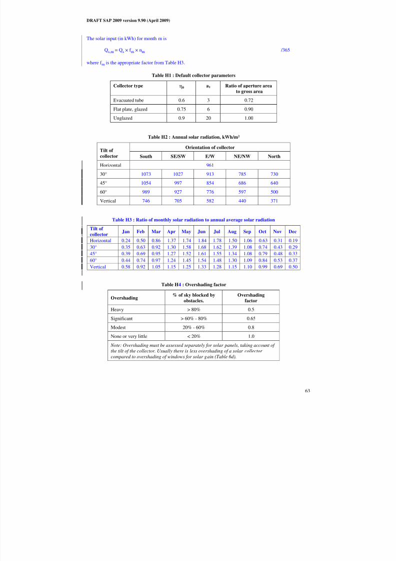
8/14/2019 Draft SAP 2009 Main Document
http://slidepdf.com/reader/full/draft-sap-2009-main-document 64/91
DRAFT SAP 2009 version 9.90 (April 2009)
63
The solar input (in kWh) for month m is
Qs,m = Qs × f m × nm /365
where f m is the appropriate factor from Table H3.
Table H1 : Default collector parameters
Collector type η0 a1 Ratio of aperture area
to gross area
Evacuated tube 0.6 3 0.72
Flat plate, glazed 0.75 6 0.90
Unglazed 0.9 20 1.00
Table H2 : Annual solar radiation, kWh/m²
Orientation of collectorTilt of
collector South SE/SW E/W NE/NW North
Horizontal 961
30° 1073 1027 913 785 730
45° 1054 997 854 686 640
60° 989 927 776 597 500
Vertical 746 705 582 440 371
Table H3 : Ratio of monthly solar radiation to annual average solar radiation
Tilt of
collectorJan Feb Mar Apr May Jun Jul Aug Sep Oct Nov Dec
Horizontal 0.24 0.50 0.86 1.37 1.74 1.84 1.78 1.50 1.06 0.63 0.31 0.19
30° 0.35 0.63 0.92 1.30 1.58 1.68 1.62 1.39 1.08 0.74 0.43 0.29
45° 0.39 0.69 0.95 1.27 1.52 1.61 1.55 1.34 1.08 0.79 0.48 0.33
60° 0.44 0.74 0.97 1.24 1.45 1.54 1.48 1.30 1.09 0.84 0.53 0.37
Vertical 0.58 0.92 1.05 1.15 1.25 1.33 1.28 1.15 1.10 0.99 0.69 0.50
Table H4 : Overshading factor
Overshading % of sky blocked byobstacles.
Overshadingfactor
Heavy > 80% 0.5
Significant > 60% - 80% 0.65
Modest 20% - 60% 0.8
None or very little < 20% 1.0
Note: Overshading must be assessed separately for solar panels, taking account of
the tilt of the collector. Usually there is less overshading of a solar collector
compared to overshading of windows for solar gain (Table 6d).

8/14/2019 Draft SAP 2009 Main Document
http://slidepdf.com/reader/full/draft-sap-2009-main-document 65/91
DRAFT SAP 2009 version 9.90 (April 2009)
64
H2 Community solar DHW
Where solar panels are used in a community heating system, the total collector area and the total dedicated
solar store volume should be divided between the dwellings in proportion to the total floor area of the
dwellings (these can be rounded to the nearest 0.01 m² and 1 litre).
Example. A block of 24 flats, eight with floor area of 50 m² and 16 with floor area of 60 m². Total aperture
area of solar panels is 40 m² and the total solar storage volume is 1000 litres. The small flats are each
assigned 1.47 m² and 37 litres, and the larger flats 1.76 m² and 44 litres.
The calculation is done as described in H1 for single systems, with the above parameters and the
orientation, pitch and overshading of the panels set at values representative of the whole installation.
Usually the solar store is separate and the arrangement is equivalent to that of diagram a) in Figure H2.

8/14/2019 Draft SAP 2009 Main Document
http://slidepdf.com/reader/full/draft-sap-2009-main-document 66/91
DRAFT SAP 2009 version 9.90 (April 2009)
65
Appendix I (not used)

8/14/2019 Draft SAP 2009 Main Document
http://slidepdf.com/reader/full/draft-sap-2009-main-document 67/91
DRAFT SAP 2009 version 9.90 (April 2009)
66
Appendix J: Seasonal efficiency for solid fuel boilers from test data
This appendix specifies how to obtain a seasonal efficiency from test data on a solid fuel boiler that is
provided in the boiler database. A database record for a solid fuel boiler includes:
- SAP seasonal efficiency, %- Fuel input, heat to water and heat to room from test at full load, kW
- Fuel input, heat to water and heat to room from test at part load, kW
J1 SAP seasonal efficiency is given
If the SAP seasonal efficiency is given, that value is used for both space and water heating, and the other
data is disregarded.
J2 SAP seasonal efficiency is not given
If the SAP seasonal efficiency is blank, the appropriate efficiency for use in the calculations is obtained asfollows.
J2.1 Part load data is available
The efficiency at full load is obtained from:
loadfullatinputfuel
load)fullatroom(heat toload)fullatwater(heat to100E full
+×= (J1)
and the efficiency at part load from:
loadpartatinputfuel
load)partatroom(heat toload)partatwater(heat to100Epart
+×= (J2)
If the boiler is outside the boundary of the dwelling as defined in section 1, “Dwelling dimensions”, the heatto room is omitted from (J1) and (J2).
The seasonal efficiency is then:
Seasonal efficiency = 0.5 (Efull + Epart) (J3)
J2.2 Part load data is not available
If the data for the part load test is blank, the part load efficiency is taken as 95% of the full load efficiency,
so that:
Seasonal efficiency = 0.975 Efull (J4)
J2.3 Rounding
The seasonal efficiency should be rounded to one decimal place before using it in calculations.
J3 Heating type and responsiveness
The heating type and responsiveness is that for the applicable type of appliance given in Table 4a.

8/14/2019 Draft SAP 2009 Main Document
http://slidepdf.com/reader/full/draft-sap-2009-main-document 68/91
DRAFT SAP 2009 version 9.90 (April 2009)
67
Appendix K: Thermal bridging
Thermal bridges that occur at junctions between building elements are included in the calculation of
transmission heat losses.
The quantity which describes the heat loss associated with a thermal bridge is its linear thermal
transmittance, Ψ. This is a property of a thermal bridge and is the rate of heat flow per degree per unitlength of the bridge, that is not accounted for in the U-values of the plane building elements containing the
thermal bridge*.
The transmission heat loss coefficient associated with non-repeating thermal bridges is calculated as:
( )∑ Ψ×= LHTB (K1)
where L is the length of the thermal bridge over which Ψ applies.
If details of the thermal bridges are not known, use
∑= expTB AyH (K2)
where Aexp is the total area of exposed elements calculated at worksheet (31), m2, and y = 0.15.
If the junction detail is as recommended in Accredited Construction Details†, the Ψ-value associated with
that junction can be taken from Table K1.
Alternatively values of Ψ can be determined from the results of numerical modelling, or they can be
derived from measurement. Values of Ψ for particular cases should be calculated in accordance with BREIP 1/06 , Assessing the effects of thermal bridging at junctions and around openings, and BR 497,
Conventions for calculating linear thermal transmittance and temperature factors.
There are four possibilities for specifying the thermal bridging:
1) No information on thermal bridging. Use y = 0.15 in equation (K2).
2) All detailing conforms with Accredited Construction Details. Use values from Table K1 in equation
(K1).
3) A value of y has been calculated for a particular house design from individual Ψ values. Use this valueincreased by a factor of 1.25 in equation (K2). Documentary evidence as to its calculation must be
available.
4) Ψ values are known for each junction type. Use equation (K1) with the total length of each junction
type. In this case values may be taken from Table K1 for Accredited Construction Details or they may
be calculated according to BR 497, in the latter case increased by a factor of 1.25. All junction types
must be included.
*
Repeating thermal bridges that occur throughout a building element, for example timber studs or joists, aretaken into account in the U-value of the element and so are not included here.
† (reference to be updated)

8/14/2019 Draft SAP 2009 Main Document
http://slidepdf.com/reader/full/draft-sap-2009-main-document 69/91
DRAFT SAP 2009 version 9.90 (April 2009)
68
Table K1 Values of Ψ for different types of junctions conforming
with Accredited Construction Details
Junction detail Ψ (W/m·K)
Steel lintel with perforated steel base plate 0.50
Other lintels (including other steel lintels) 0.30
Sill 0.04
Jamb 0.05
Ground floor 0.16
Intermediate floor within a dwelling 0.07
Intermediate floor between dwellings (in blocks of flats)a) 0.07
Balcony within a dwellingb)
0.00
Balcony between dwellingsa) b)
0.02
Eaves (insulation at ceiling level) 0.06Eaves (insulation at rafter level) 0.04
Gable (insulation at ceiling level) 0.24
Gable (insulation at rafter level) 0.04
Corner (normal) 0.09
Corner (inverted – internal area greater than external area) -0.09
Junctionswith an
external wall
Party wall between dwellings a) 0.03
Ground floor 0.08
Intermediate floor within a dwelling 0.00
Intermediate floor between dwellings (in blocks of flats) 0.00
Gable (insulation at ceiling level) 0.12
Junctions
with a party
walla)
Gable (insulation at rafter level) 0.02
a) Value of Ψ is applied to each dwelling b)
This is an externally supported balcony (the balcony slab is not a continuation of the floorslab) where the wall insulation is continuous and not bridged by the balcony slab
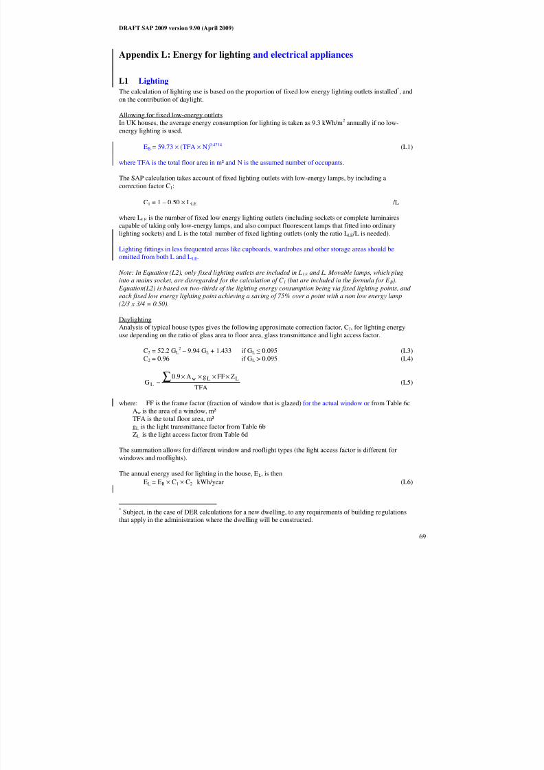
8/14/2019 Draft SAP 2009 Main Document
http://slidepdf.com/reader/full/draft-sap-2009-main-document 70/91
DRAFT SAP 2009 version 9.90 (April 2009)
69
Appendix L: Energy for lighting and electrical appliances
L1 Lighting
The calculation of lighting use is based on the proportion of fixed low energy lighting outlets installed*, and
on the contribution of daylight.
Allowing for fixed low-energy outlets
In UK houses, the average energy consumption for lighting is taken as 9.3 kWh/m2
annually if no low-
energy lighting is used.
EB = 59.73 × (TFA × N)0.4714 (L1)
where TFA is the total floor area in m² and N is the assumed number of occupants.
The SAP calculation takes account of fixed lighting outlets with low-energy lamps, by including a
correction factor C1:
C1 = 1 – 0.50 × LLE /L
where LLE is the number of fixed low energy lighting outlets (including sockets or complete luminaires
capable of taking only low-energy lamps, and also compact fluorescent lamps that fitted into ordinary
lighting sockets) and L is the total number of fixed lighting outlets (only the ratio LLE /L is needed).
Lighting fittings in less frequented areas like cupboards, wardrobes and other storage areas should be
omitted from both L and LLE.
Note: In Equation (L2), only fixed lighting outlets are included in L LE and L. Movable lamps, which plug
into a mains socket, are disregarded for the calculation of C 1 (but are included in the formula for E B).
Equation(L2) is based on two-thirds of the lighting energy consumption being via fixed lighting points, and
each fixed low energy lighting point achieving a saving of 75% over a point with a non low energy lamp
(2/3 x 3/4 = 0.50).
DaylightingAnalysis of typical house types gives the following approximate correction factor, C2, for lighting energy
use depending on the ratio of glass area to floor area, glass transmittance and light access factor.
C2 = 52.2 GL2 – 9.94 GL + 1.433 if GL ≤ 0.095 (L3)
C2 = 0.96 if GL > 0.095 (L4)
TFA
ZFFgA9.0G
LLwL∑ ××××
= (L5)
where: FF is the frame factor (fraction of window that is glazed) for the actual window or from Table 6cAw is the area of a window, m²
TFA is the total floor area, m²
gL is the light transmittance factor from Table 6b
ZL is the light access factor from Table 6d
The summation allows for different window and rooflight types (the light access factor is different for
windows and rooflights).
The annual energy used for lighting in the house, EL, is then
EL = EB × C1 × C2 kWh/year (L6)
*Subject, in the case of DER calculations for a new dwelling, to any requirements of building regulations
that apply in the administration where the dwelling will be constructed.

8/14/2019 Draft SAP 2009 Main Document
http://slidepdf.com/reader/full/draft-sap-2009-main-document 71/91
DRAFT SAP 2009 version 9.90 (April 2009)
70
The lighting energy use in kWh in month m (January = 1 to December = 12) is
EL,m = EL × [1 + 0.5 * cos(2π (m - 0.2) / 12)] × nm / 365 (L7)
and the associated internal heat gain in watts is
GL,m = EL,m × 0.85 × 1000 /(24 × nm) (L8)
where nm is the number of days in month m. The factor 0.85 is an allowance for 15% of the total lighting
usage being external to the dwelling. When lower internal heat gains are assumed for the calculation,
GL,m = 0.67 × EL,m × 0.85 × 1000 /(24 × nm) (L8a)
(L6) is used for the annual energy use for lighting. (L8) or (L8a) is used for the heat gain from lighting ineach month in Section 5 of the calculation.
L2 Electrical appliances
The annual energy use in kWh for electrical appliances is:
EA = 207.8 × (TFA × N)0.4714
(L9)
where TFA is the total floor area in m² and N is the assumed number of occupants (see Table 1).
The appliances energy use in kWh in month m (January = 1 to December = 12) is
EA,m = EA × [1 + 0.157 * cos(2π (m - 1.78) / 12)] × nm / 365 kWh (L10)
and the associated internal heat gain in watts is
GA,m = EA,m × 1000 /(24 × nm) (L11)
where nm is the number of days in month m. When lower internal heat gains are assumed for thecalculation,
GA,m = 0.67 × EA,m × 1000 /(24 × nm) (L11a)
The annual CO2 emissions in kg/m²/year associated with electrical appliances is
EA × EFelectricity / TFA (L12)
where EFelectricity is the emission factor for electricity (Table 12).
(L11) or (L11a) is used for the heat gain from appliances in each month in Section 5 of the calculation.(L12) is used for the annual emissions for appliances in Section 15 of the calculation.
L3 Cooking
Internal heat gains in watts from cooking:
GC = 35 + 7 N (L13)
When lower internal heat gains are assumed for the calculation,
GC = 23 + 5 N (L13a)
CO2 emissions in kg/m²/year associated with cooking:
(131 + 26 N) / TFA (L14)

8/14/2019 Draft SAP 2009 Main Document
http://slidepdf.com/reader/full/draft-sap-2009-main-document 72/91
DRAFT SAP 2009 version 9.90 (April 2009)
71
(L13) or (L13a) is used for the heat gain from cooking in Section 5 of the calculation. (L14) is used for the
annual emissions for cooking in Section 15 of the calculation.

8/14/2019 Draft SAP 2009 Main Document
http://slidepdf.com/reader/full/draft-sap-2009-main-document 73/91
DRAFT SAP 2009 version 9.90 (April 2009)
72
Appendix M: Energy from Photovoltaic (PV) technology, small and
micro wind turbines and small-scale hydro-electric generators
The procedures in this appendix give annual electricity generation, which is added in at the end of the
calculation.
This appendix may be extended in future to cover other technologies.
M1 Photovoltaics
Photovoltaic technology converts sunlight directly into electricity. It works during daylight hours but more
electricity is produced when the sunshine is more intense (a sunny day) and is striking the PV modules
directly. Unlike solar systems for heating water, PV technology does not produce heat. Instead, PV
produces electricity as a result of interaction of sunlight with semi-conductor materials in the PV cells.
For SAP calculations, the energy produced per year depends on the installed peak power (kWp) of the PV
module (the peak power corresponds to the rate of electricity generation in bright sunlight, formally defined
as the output of the module under radiation of 1 kW/m² at 25°C). PV modules are available in a range of
types and some produce more electricity per square metre than others (the range for currently available
types is from about 30 to 125 watts peak per m²), and the peak power depends on the type of module as wellas its effective area. In the UK climate, an installation with 1 kWp typically produces about 800 kWh of
electricity per year (at favourable orientation and not overshaded).
At times of high solar radiation the PV array may generate more electricity than the instantaneous
electricity demand within the dwelling. Arrangements must be made for the surplus electricity to be
exported to the grid via a dual or two-way electricity meter.
The procedure for PV is as follows.
1) Establish the installed peak power of the PV unit (kWp).
2) The electricity produced by the PV module in kWh/year is
0.8 × kWp × S × ZPV (M1)
where S is the annual solar radiation from Table H2 (depending on orientation and pitch),
and ZPV is the overshading factor from Table H4.
If there are two PV modules, e.g. at different tilt or orientation, apply equation (M1) to each and sumthe annual electricity generation.
3) The cost saving associated with the generated electricity depends on whether it is used directly within
the dwelling or whether it is exported. Electricity used directly within the dwelling is valued at the unit
cost for purchased electricity (usually the standard tariff, or the day rate in the case of an off-peak
tariff). Electricity exported is valued at the price for electricity sold to the grid.The effective price depends on a factor β, which is in the range 0.0 to 1.0 and is defined as the
proportion of the generated electricity that is used directly within the dwelling. The value of β dependson the coincidence of electricity generation and electricity demand within the dwelling. At present the
value of β = 0.50 should be used for SAP calculations: this will be reviewed in future if relevant databecomes available.
The fuel price used in the calculation of box (95a) is:
β × normal electricity price + (1 - β) × exported electricity price.
4) For calculation of CO2 emissions, the emissions factor for grid-displaced electricity from Table 12 is
used in the calculation of box (110). The same factor applies to all electricity generated, whether used
within the dwelling or exported.

8/14/2019 Draft SAP 2009 Main Document
http://slidepdf.com/reader/full/draft-sap-2009-main-document 74/91
DRAFT SAP 2009 version 9.90 (April 2009)
73
5) Where the PV array is mounted on the building concerned or wholly within its curtilage, and its output
is directly connected to the building's electricity supply, the output calculated by (M1) is included in
the worksheet at box (95).
In the case of a building containing more than one dwelling, e.g. a block of flats, then:
a) if the PV output goes to particular individual flats, the annual output is credited to the flatsconcerned;
b) otherwise the total electricity generated is divided amongst all the flats in the block in proportion
to their floor area.
In case a) an inverter is needed for each flat with a PV electricity supply. In case b) there will usuallybe a single inverter for the total PV array and the electricity generated fed to the landlord supply or to
the distribution system for the flats (with provision for export of electricity generated in excess of
instantaneous demand).
6) In other cases the output calculated by (M1) divided by the total floor area of buildings on the
development may be entered in (ZC6), see Section 15, when the total net CO2 emissions are being
calculated.
M2 Micro wind turbines on the building or within its curtilage
The procedure given below applies to small wind turbines mounted either on the roof of the dwelling or on
a nearby mast within its curtilage. For other cases see M3.
The performance of wind turbines is very sensitive to the local wind conditions. The procedure is based on
typical conditions using a formula given by GreenSpec*
and the wind speed correction factors given inMIS 3003 †.
At times of higher wind speeds the wind turbine may generate more electricity than the instantaneous
electricity demand within the dwelling. Arrangements must be made for the surplus electricity to beexported to the grid via a dual or two-way electricity meter.
It should be noted that the procedure given in this Appendix is an approximate one and in particular that the
correction factors in MIS 3003, while representing the best currently available estimates, are known to be
imprecise. Also, it is based on generic turbine technology. It will be revised as better information becomes
available.
Meanwhile the procedure is considered as valid for the purposes of calculations by SAP 2005 when:- no part of the turbine blade dips below the level of the ridge of the roof;
- there are no obstructions significantly larger than the building within a radius of 10 times the building
height.
It should not be applied if those conditions are not met.
1) The output power Pwind of one turbine in watts at a wind speed of s m/s is:
Pwind = CP × A × PA × G × IE (M2)
where
CP is the aerodynamic power coefficient (efficiency of the rotor to convert energy)
A is the swept area of the blade
PA is the power density of the wind = 0.6125 s³
* www.greenspec.co.uk/html/energy/windturbines.html (accessed 20 September 2007)
†
Microgeneration Installation Standard MIS 3003, Requirements for contractors undertaking the supply,design, installation, set to work commissioning and handover of micro and small wind turbine systems,
BRE Certification Ltd, 2007, http://www.redbooklive.com/page.jsp?id=135 (accessed 20 September 2007)

8/14/2019 Draft SAP 2009 Main Document
http://slidepdf.com/reader/full/draft-sap-2009-main-document 75/91
DRAFT SAP 2009 version 9.90 (April 2009)
74
G is the efficiency of the generator
IE is efficiency of the inverter (allowing for power drawn by the inverter) *.
2) The annual energy in kWh/year is related to the output at average wind speed by
Ewind = Nturbines × Pwind × 1.9 × 8766 × 0.001 (M3)
where Nturbines is the number of wind turbines, 1.9 is a parameter representing the wind speed variation
function and 8766 is the average number of hours per year.
If there is more than one turbine of differing hub height or blade diameter, apply equation (M3) to each
and sum the annual electricity generation.
3) The product of CP, G and IE is taken as 0.24.
4) The area A is 0.25 × π × (rotor diameter)².
5) The average wind speed is taken as 5.0 m/s multiplied by the appropriate correction factor from
Table M1†.
6) The total electricity produced as calculated in step 2) above is entered in box (95) of the worksheet.
7) For calculation of the cost savings the factor β (see Section M1) is 0.7.
8) For calculation of CO2 emissions, the emissions factor for grid-displaced electricity from Table 12
applies to all electricity generated, whether used within the dwelling or exported.
Table M1 : Wind speed correction factors
Terrain type Height of turbine
hub above ridge
of roof (m)*
Correction
factor
10 0.56
5 0.51
2 0.40
Dense urban
(city centres with mostly closely spaced buildings of
four storeys or higher)
0 0.28
6 0.67
4 0.61
2 0.53
Low rise urban / suburban
(town or village situations with other buildings well
spaced)
0 0.39
12 1.00
7 0.94
2 0.86
Rural
(open country with occasional houses and trees)
0 0.82
* must be at least half the rotor diameter
Use linear interpolation for intermediate values. For hub height higher than the maximum
*Equation (M2) differs from that on the GreenSpec website by including IE. The latter is included so as to
provide the system output rather than the turbine output.†
Factors in Table M1 derived from data in The Designer's Guide to Wind Loading of Structures, N.J. Cook,Butterworths, 1986

8/14/2019 Draft SAP 2009 Main Document
http://slidepdf.com/reader/full/draft-sap-2009-main-document 76/91
DRAFT SAP 2009 version 9.90 (April 2009)
75
given for the terrain type use the highest for that terrain type (i.e. 0.56, 0.67 or 1.00). This is
because of limitations of current knowledge; the table will be revised in future.
M3 Wind turbines associated with more than one dwelling
This refers to wind turbines such as might be installed as part of a housing development. They are notincluded for the assessment of ratings but can be included in the assessment of an overall CO2 emissionfigure inclusive of all energy uses (including appliances and cooking), see Section 15. If not actually on the
site they can be included provided that they are connected to the site via private wires. Electricity surplus to
the instantaneous electricity demand of the dwellings is fed into the electricity grid.
The total annual output of wind turbines should be estimated using the procedure given in Microgeneration
Installation Standard MIS 3003. It is recommended that the wind speed at the intended location ismonitored for at least a year in order ascertain the local wind conditions but if that data is not available the
wind speed can be estimated from the NOABL database as described in MIS 3003 (this is subject to the
limitation in MIS 3003 of a maximum 50 kW rated output at a wind speed of 11 m/s).
The output from the wind turbines should be apportioned between the dwellings concerned on the basis of
their floor area, by dividing the total annual output by the total floor area of buildings on the development,and entered in kWh/m² into box (ZC6) in Section 15.
M4 Small-scale hydro-electric generators
Hydro-electric generation is possible only in a small number of situations. Each case is different and
detailed calculations of the electricity generated are outside the scope of SAP 2005.
Where small-scale hydro-electric generation is applicable, it may be allowed for in SAP calculations asfollows.
1) The total electricity generated per year is calculated and signed off by a suitably qualified engineer
having adequate competence in the assessment of the technology. In case of doubt guidance should be
sought from BRE.
2) Where more than one dwelling benefits from the hydro-electric generation, the kWh per year
attributable to each dwelling is obtained from the total in step 1) apportioned to each dwelling
according to the total floor area of the dwelling.
3) For calculation of the cost savings the factor β (see Section M1) is 0.4.
4) For calculation of CO2 emissions, the emissions factor for grid-displaced electricity from Table 12
applies to all electricity generated, whether used within the dwelling or exported.
5) Where the electricity generator is within the curtilage of the building, and its output is directly
connected to the building's electricity supply, the output is entered in the worksheet at box (95).
6) In other cases the electricity generated divided by the sum of the floor areas of the buildings concerned
may be entered in (ZC6), see Section 15, when the total net CO2 emissions are being calculated.

8/14/2019 Draft SAP 2009 Main Document
http://slidepdf.com/reader/full/draft-sap-2009-main-document 77/91
DRAFT SAP 2009 version 9.90 (April 2009)
76
Appendix N: Micro-cogeneration (also known as micro-CHP)
N1 Overview
Micro-cogeneration provides both heat and electricity. It is assumed to be heat-led, meaning that it is
allowed to operate only when there is a demand for space heating or hot water. The domestic application of micro-cogeneration is treated as an alternative to a conventional domestic boiler, using mains gas, LPG, oil
or solid fuel. It is also assumed that it is connected to the public electricity supply in such a way that all
surplus generated electricity is exported. It provides space heating throughout the heating season, and hot
water service for either (a) the whole of the year, or (b) none of the year.
The characteristics of micro-cogeneration are described by data derived from laboratory tests. The test data
is used to calculate parameters related to the annual energy performance of the micro-cogeneration package.
Results (known as “intermediate results”) from the annual energy performance method are used for SAP as
described in N2.
Any space heating requirements not met by the micro-cogeneration package are assumed to be provided by
secondary heating appliances (if provided) or by electric room heaters. If the package provides domestic hot
water it is assumed to provide all water heating needs.
The heat produced by the package and the electrical energy consumed/generated are based on operation
during an average year, taking account of the output rating of the appliance and the design heat loss for the
dwelling into which it is installed. The amount of auxiliary heating is determined by the plant size ratio (full
output power of the micro-cogeneration package divided by the design heat loss). If the plant size ratio is
less than 0.5 then the package cannot be regarded as the primary heating system, and the performance dataare not valid for SAP.
The electricity consumed/generated will normally be negative, and then represents the net electricity
provided by the micro-cogeneration package that is available to offset electricity that would otherwise be
taken from the public electricity supply grid or, to the extent that instantaneous generation exceeds
instantaneous electricity demand, is exported to the grid.
The thermal efficiency of the micro-cogeneration package is used in the normal way for the calculation of
energy requirements for space heating and, if supplied by the micro-cogeneration package, water heating.
The electricity consumed (or the net electricity generation) is scaled according to the net energy use as
obtained in the SAP calculation.
N2 Interpolation of result sets
The intermediate results from the annual energy performance method are produced in sets, with each set
calculated for a different plant size ratio (e.g. 0.5, 1.0, 1.5 and 4.0). The plant size ratio is defined as the
maximum heat output of the micro-cogeneration package divided by the design heat loss of the dwelling.
Each set of results contains the data in Table N1. The data to be used for SAP calculations are provided by
way of the boiler database, each database record for a micro-cogeneration package containing the output
power of the package and a number of sets of intermediate results.

8/14/2019 Draft SAP 2009 Main Document
http://slidepdf.com/reader/full/draft-sap-2009-main-document 78/91
DRAFT SAP 2009 version 9.90 (April 2009)
77
Table N1: Set of intermediate results from the annual energy performance method
Data item Symbol Unit
Plant size ratio for which data apply PSR -
Annual heat generated for space
heating
Qsp kWh
Annual heat generated for domestichot water, if any
Qhw kWh
Annual auxiliary heating requirement Qaux kWh
Heating season* thermal efficiency ηhs -
Summer season thermal efficiency ηsum -
The electricity consumed or, if
negative, net electricity generated,
during the heating season
Emc,hs kWh
The electricity consumed or, if
negative, net electricity generated.,during the summer season
Emc,sum kWh
Number of days operating for
16 hours instead of 9N16,9 days
Number of days operating for24 hours instead of 9
N24,9 days
Number of days operating for
24 hours instead of 16N24,16 days
The plant size ratio (PSR) for the dwelling is calculated using the maximum output of the micro-
cogeneration package and the design heat loss of the dwelling taken as the heat loss coefficient, box (37) of
the worksheet, multiplied by a temperature difference of 20 K. In the case of a range-rated package, the
PSR for the dwelling is calculated assuming that it is set to the top of the range. The intermediate results
applicable to the dwelling are then obtained by linear interpolation between the intermediate results†
for the
two sets of data whose PSRs enclose that of the actual dwelling. The dwelling-specific result sets are used
in equations (N1) to (N6) to calculate the parameters used in the SAP calculation.
N3 Calculation of space and water heating and electricity produced
The electricity used by any fans within the package is included in Emc,hs and Emc,sum and is not included
separately in the SAP calculation, thus box (87b) is zero.
If the micro-cogeneration package includes a central heating system pump to circulate water through the
heat emitters the electricity for it is included in Emc,hs and the heat gain from it is allowed for in ηsp. In that
case no allowance for a central heating pump is included in box (53e) and box (87a) is zero. If the packagedoes not include a central heating pump, it is provided separately outside the package, and the gain from
Table 5a is included in box (53e) and electricity use from Table 4f is included in box (87a).
Mean internal temperature
The micro-cogeneration package, when undersized in relation to the dwelling's design heat loss, can
provide space heating needs on more days of the heating season if it operates for 16 hours per day or
continuously. The seasonal thermal efficiency and electricity generated in the intermediate results are based
on the hours of operation indicated by the parameters N16,9, N24,9 and N24,16 for a nominal heating season
length of 238 days (34 weeks). For the normal SAP heating schedule, this would comprise 68 weekend days
*
The heating season and summer season together comprise a whole year.†For the efficiency values, the interpolated efficiency is the reciprocal of linear interpolation between the
reciprocals of the efficiencies. Round N16,9, N24,9 and N24,16 to the nearest integer.

8/14/2019 Draft SAP 2009 Main Document
http://slidepdf.com/reader/full/draft-sap-2009-main-document 79/91
DRAFT SAP 2009 version 9.90 (April 2009)
78
with 16 hours of heating and 170 weekdays with 9 hours of heating (2 hours in the morning and 7 hours in
the evening). The mean internal temperature for the heating season is
MIT = [ (N24,16 + N24,9) T24 + (68 – N24,16 + N16,9) T16 + (170 – N16,9 – N24,9) T9 ] / 238 (N1)
where T24, T16 and T9 are the mean temperatures for 24, 16 and 9 hours of heating, calculated using Tables
N2, N3 and N4 respectively instead of Table 9.
Table N2: Heating periods and heating temperatures continuous heating
Living area Elsewhere
Temperature
Th (°C)
Hours of heating
off
toff
Heating
control
(Table 4e)
Temperature
Th °C
Hours of heating off
toff
1 21 – 0.5 HLP 0 and 0
2 21 – HLP + 0.085 HLP² 0 and 021 0 and 0
3 21 – HLP + 0.085 HLP² 0 and 0
Table N3: Heating periods and heating temperatures for 16 hours heating per day
Living area Elsewhere
Temperature
Th (°C)
Hours of heating
off
toff
Heating
control
(Table 4e)
Temperature
Th °C
Hours of heating off
toff
1 21 – 0.5 HLP 0 and 8
2 21 – HLP + 0.085 HLP² 0 and 821 0 and 8
3 21 – HLP + 0.085 HLP² 9 and 8
Table N4: Heating periods and heating temperatures for 9 hours heating per day
Living area Elsewhere
Temperature
Th (°C)
Hours of heating
off
toff
Heating
control
(Table 4e)
Temperature
Th °C
Hours of heating off
toff
1 21 – 0.5 HLP 7 and 8
2 21 – HLP + 0.085 HLP² 7 and 821 7 and 8
3 21 – HLP + 0.085 HLP² 9 and 8
Efficiency
Use the heat efficiency ηhs in box (83) for space heating.
If the micro-cogeneration package provides both space and hot water heating, use the heat efficiency ηhs for
water heating in the heating season and ηsum for water heating in summer
If the package only provides space heating specify a separate hot water system such as an electric
immersion heater.
If the package is a condensing type, the efficiency adjustments in Table 4c(1) apply where relevant to
efficiency in the heating season.
summerwater
erintw
space
waterspacewater
E
Q
E
Q
QQE
+
+= (N2)

8/14/2019 Draft SAP 2009 Main Document
http://slidepdf.com/reader/full/draft-sap-2009-main-document 80/91
DRAFT SAP 2009 version 9.90 (April 2009)
79
Hot water storage losses
If the micro-cogeneration package contains within it a storage vessel for domestic hot water that was
included in the energy performance tests, heat losses associated with hot water storage are included in theintermediate results and zero is entered for the cylinder loss (46) and the primary loss (48).
If the package does not contain a storage vessel for domestic hot water, a cylinder is specified separately
and the cylinder loss and primary loss are included in the SAP calculation.
Secondary heating
The auxiliary heating requirement Qaux is provided by a secondary heating system (any system from the
room heater section of Table 4a). The secondary fraction is calculated from
auxsp
aux
QSF
+= (N4)
Electricity
If the package provides both space and hot water heating, the electricity consumed or generated is scaled to
the actual heat requirement of the dwelling for both heating and hot water:
[ ] [ ]sum,mc
hwhs,mc
hwseasonsp
EQ
)51(boxE
Qf Q
(51)box0.66)SF1((81)box*E ×+×
×+
×+−×= (N5)
where f season = 0.66 is the heating season as a fraction of a year.
If the package provides space heating only, the electricity consumed or generated is scaled to the actual
space heating requirement of the dwelling:
hs,mcsp
EQ
)SF1()81(box*E ×
−×= (N6)
If E* is positive, enter E* in box (96) and use the unit price for standard tariff electricity in the calculation
of box (96a).
If E* is negative, enter E* in box (95). The cost saving associated with the net generated electricity depends
on whether it is used directly within the dwelling or whether it is exported. Electricity used directly within
the dwelling is valued at the unit cost for purchased electricity (usually the standard tariff, or the day rate in
the case of an off-peak tariff). Electricity exported is valued at the price in Table 12 for electricity sold to
the grid.
The effective price depends on a factor β, which is in the range 0.0 to 1.0 and is defined as the proportion of
the generated electricity that is used directly within the dwelling. The value of β depends on the coincidence
of electricity generation and electricity demand within the dwelling. At present the value of β = 0.40 should
be used for SAP calculations: this will be reviewed in future if relevant data become available. The fuel
price used in the calculation of box (95a) is then:
β x normal electricity price + (1 - β) x exported electricity price.

8/14/2019 Draft SAP 2009 Main Document
http://slidepdf.com/reader/full/draft-sap-2009-main-document 81/91
DRAFT SAP 2009 version 9.90 (April 2009)
80
Appendix O (not used)

8/14/2019 Draft SAP 2009 Main Document
http://slidepdf.com/reader/full/draft-sap-2009-main-document 82/91
DRAFT SAP 2009 version 9.90 (April 2009)
81
Appendix P: Assessment of internal temperature in summer
This appendix provides a method for assessing the propensity of a house to have high internal temperature
in hot weather. It does not provide an estimate of cooling needs. The procedure is not integral to SAP and
does not affect the calculated SAP rating or CO2 emissions.
The calculation is related to the factors that contribute to internal temperature: solar gain (taking account of orientation, shading and glazing transmission); ventilation (taking account of window opening in hot
weather), thermal capacity and mean summer temperature for the location of the dwelling.
Further information about techniques to avoid overheating can be found in ‘Reducing overheating– a
designer’s guide’, CE 129, Energy Efficiency Best Practice in Housing, Energy Saving Trust, London(2005).
P1 Assessment procedure
The procedure is undertaken for the months of June, July and August.
1. Obtain a value for the effective air change rate during hot weather. Indicative values based on the
procedure in BS 5925*
are given in Table P1.
Table P1: Effective air change rate
Window opening Effective air change rate in ach
Trickle
vents only
Windows
slightly open
(50 mm)
Windows
open half
the time
Windows
fully open
Single storey dwelling
(bungalow, flat)Cross ventilation possible
0.1 0.8 3 6
Single storey dwelling
(bungalow, flat)
Cross ventilation not possible
0.1 0.5 2 4
Dwelling of two or more storeys
windows open upstairs and
downstairs
Cross ventilation possible
0.2 1 4 8
Dwelling of two or more storeyswindows open upstairs and
downstairs
Cross ventilation not possible
0.1 0.6 2.5 5
Cross ventilation can be assumed only if the at least half of the storeys in the dwelling have windowson opposite sides and there is a route for the ventilation air. Normally bungalows and two storey houses
can be cross ventilated because internal doors can be left open. Three storey houses or other situationswith two connected storeys of which one is more than 4.5 m above ground level often have floors
which have fire doors onto stairs that prevent cross ventilation.
Slightly open refers to windows that can be securely locked with a gap of about 50 mm. Often this
option will not give sufficient ventilation.
Windows on ground floors cannot be left open all night because of security issues. Windows on other
floors can. Fully open would refer to dwellings where security is not an issue (e.g. an upper floor flat)
or where there is secure night time ventilation (e.g. by means of grilles, shutters with vents or purpose-
made ventilators). In most cases where there are ground and upper floor windows ‘windows open half
* BS 5925:1991, Code of practice for ventilation principles and design for natural ventilation

8/14/2019 Draft SAP 2009 Main Document
http://slidepdf.com/reader/full/draft-sap-2009-main-document 83/91
DRAFT SAP 2009 version 9.90 (April 2009)
82
the time’ would be applicable, which refers principally to night-time ventilation (ground floor evening
only, upper floors open all night).
If there is a mechanical ventilation system providing a specified air change rate, that rate can be used
instead.
2. Calculate the ventilation heat loss, summervH , using the formula:
Vn33.0Hsummerv ××= (P1)
where:
n = air change rate during hot weather, achV = volume of the heated space of the dwelling, m3
3. Calculate the heat loss coefficient under summer conditions:
H = total fabric heat loss + summervH (P2)
The total fabric heat loss is the same as for the heating season (box (35) of the worksheet).
4. Calculate the solar gains for the summer month , summersolarG , using the solar flux for the appropriatemonth from Table 10.
( )∑ ×××××= ⊥ summerwsummersolar ZFFgSA9.0G (P3)
where:
0.9 is a factor representing the ratio of typical average transmittance to that at normal incidence
Aw is the area of an opening (a window, roof window or fully glazed door), m²
S is the solar flux on a surface during the summer period from Table 6a, W/m²
g⊥ is the total solar energy transmittance factor of the glazing at normal incidence from Table 6b
FF is the frame factor for windows and doors (fraction of opening that is glazed) from Table 6c
Zsummer is the summer solar access factor
In the case of a window certified by the British Fenestration Rating Council (BFRC), see
www.bfrc.org, the quoted solar factor is gwindow which is equal to 0.9 × g⊥ × FF. The solar gain forsuch windows is calculated as
( )∑ ×××= summerwsummersolar
ZgSAG window (P4)
Solar gains should be calculated separately for each orientation and for rooflights, and totalled
according to equation (P3).
For data to calculate Zsummer see section P3.
Assume that the summer internal gains (Gi ) are equal to the winter internal gains (these are calculatedin section 5 of the SAP worksheet), except that where water heating in summer is by a summer-only
electric immersion in which case primary loss should not be included in the summer gains, so that the
total gains are:
isummersolar
GGG += (P5)
5. Calculate the summer Gain/Loss ratio:
Summer Gain/Loss ratio =H
G(P6)
6. Obtain the mean external temperature for the month, summereT , from Table 10.

8/14/2019 Draft SAP 2009 Main Document
http://slidepdf.com/reader/full/draft-sap-2009-main-document 84/91
DRAFT SAP 2009 version 9.90 (April 2009)
83
7. Obtain the threshold internal temperature which is used to estimate likelihood of high internal
temperature. This is the mean internal temperature during the summer period plus an increment related
to the thermal mass.
masssummerethreshold T
H
GTT ∆++= (P7)
where
∆Tmass = 2.0 – 0.007 × TMP if TMP < 285
∆Tmass = 0 if TMP ≥ 285
where TMP is the thermal mass parameter (for further details see Table 1c).
8. Use Table P2 to estimate tendency to high internal temperature in hot weather.
Table P2: Levels of threshold temperature corresponding to likelihood of high internal temperature
during hot weather
Tthreshold Likelihood of high internal
temperature during hot weather
< 20.5°C Not significant
≥ 20.5°C and < 22.0°C Slight
≥ 22.0°C and < 23.5°C Medium
≥ 23.5°C High
P2 Reporting of results
Results should include:- details of the house design including its thermal mass parameter and specification of any overhangs,
together with its orientation and the climatic region assumed;
- for one or more scenarios, the category from Table P2 for the months of June, July and August for stated
assumptions on occupant-determined factors (usage of blinds/curtains and window opening).
If the orientation of the dwelling is not known, the assessment should be for the orientation giving the
greatest tendency to high internal temperature.

8/14/2019 Draft SAP 2009 Main Document
http://slidepdf.com/reader/full/draft-sap-2009-main-document 85/91
DRAFT SAP 2009 version 9.90 (April 2009)
84
P3 Solar shading
Zsummer is given by
Zsummer = Zblinds (Z + Zoverhangs – 1) (P8)
subject to
Zsummer ≥ 0.1 Zblinds (P9)
where
Zblinds is a shading factor for blinds or curtains
Z is the solar access factor from Table 6dZoverhangs is a shading factor for overhangs
Table P3 gives values for Zblinds, and Tables P4 and P5 give values for Zoverhangs. If there are no overhangs,
Zoverhangs = 1.
P3.1 Curtains and blinds
Unless specifically included in the design specification a default of dark coloured curtains should be
assumed closed during daylight hours (f = 1). Shutters with window closed is compatible with windows
open half the time in Table P1 as the latter refers to night-time and Table P3 refers to daytime.
Table P3 : Shading factors for blinds, curtains or external shutters
Blind or curtain type Zblind
Net curtain (covering whole window) 0.80
Net curtain (covering half window) 0.90
Dark-coloured curtain or roller blind (note 1) 0.85
Light-coloured curtain or roller blind (note 1) 0.60
Dark-coloured venetian blind (note 2) 0.88
Light-coloured venetian blind (note 2) 0.70
Dark-coloured external shutter, window closed (note 3) 0.27
White external shutter, window closed (note 3) 0.24
Dark-coloured external shutter, window fully open (note 3) 0.85
White external shutter, window fully open (note 3) 0.65
Notes to Table P3
1. Factor applies when fully closed. If closed only for a fraction f of the daylight hours usef × Zblind + (1 – f).
2. Factor applies for venetian blind with slats at 45° against the sun. The same factor can be used if
the blind is fully closed. If closed only for a fraction f of the daylight hours use
f × Zblind + (1 – f).3. External shutters are not applicable to roof windows.

8/14/2019 Draft SAP 2009 Main Document
http://slidepdf.com/reader/full/draft-sap-2009-main-document 86/91
DRAFT SAP 2009 version 9.90 (April 2009)
85
P3.2 Overhangs
Where the overhang is at least twice as wide as the window (e.g. balconies on blocks of flats) use Table P4.
In other cases use Table P5. Interpolation may be used between rows of these tables. Usually the same
value of Zoverhangs can be applied to all the windows on a given façade on the basis of an average depth-to-
height ratio.
Table P4: Zoverhangs for wide overhangs
Orientation of windowDepth/H
N NE/NW E/W SE/SW S
0.0 1.00 1.00 1.00 1.00 1.00
0.2 0.92 0.89 0.88 0.83 0.77
0.4 0.85 0.80 0.76 0.67 0.55
0.6 0.79 0.72 0.66 0.54 0.38
0.8 0.73 0.65 0.58 0.43 0.32
1 0.69 0.59 0.51 0.36 0.30
1.2 or more 0.66 0.55 0.46 0.31 0.29
This table is to be used where the overhang is at least twice as wide as the window

8/14/2019 Draft SAP 2009 Main Document
http://slidepdf.com/reader/full/draft-sap-2009-main-document 87/91
DRAFT SAP 2009 version 9.90 (April 2009)
86
Table P5: Zoverhangs for normal overhangs
Orientation of windowDepth/H
N NE/NW E/W SE/SW S0.0 1.00 1.00 1.00 1.00 1.00
0.2 0.94 0.91 0.89 0.84 0.79
0.4 0.90 0.85 0.79 0.72 0.64
0.6 0.88 0.81 0.72 0.62 0.53
0.8 0.86 0.79 0.66 0.55 0.50
1 0.85 0.77 0.61 0.52 0.49
1.2 or more 0.84 0.76 0.57 0.50 0.48
This table is to be used where the overhang is less than twice as wide as the window

8/14/2019 Draft SAP 2009 Main Document
http://slidepdf.com/reader/full/draft-sap-2009-main-document 88/91
DRAFT SAP 2009 version 9.90 (April 2009)
87
Appendix Q: Special features and specific data
Q1 Special features
This section provides a method to allow for the benefits of new energy-saving technologies that are not
included in the published SAP specification.
This procedure may only be used for technologies whose characteristics have been independently assessed
and which are recognised as part of SAP by being described on the web page www.bre.co.uk/sap2009 or a
web page linked to it*). For recognised systems, this web page will contain details for calculating the data to
be used in the SAP calculation.
In general the technology might use additional energy from one fuel while saving energy from another fuel.
In the calculation:
SAP rating:
1. include the amount of energy saved by the technology (kWh/year) in box (87m);
2. multiply the amount of saved energy by the unit price of the fuel concerned to obtain box (95);
3. include the amount of energy used by the technology in box (87n);4. multiply the energy used by the unit price of the fuel concerned and to obtain box (96);
5. include both these items in the calculation of the total energy cost in box (97).
In the case of electricity using an off-peak tariff the fractions of electricity at the high and low rates are
needed to determine the appropriate price.
CO2 Emissions:1. the amount of energy saved by the technology (kWh/year) in box (87m) is multiplied by the
appropriate emission factor and subtracted from the total CO2 emissions;
2. the amount of energy used by the technology (kWh/year) in box (87n) is multiplied by the appropriate
emission factor and added to the total CO2 emissions.
Note. Where more than one such technology is applicable the above procedure is applied separately for
each.
Q2 Specific data
A similar mechanism will be used, if appropriate, to permit the use of data specific to a technology instead
of the data provided in the SAP tables. For recognised data types, the web page mentioned above will give
details of the conditions for accepting the data and its applicability within the SAP calculation.
* One such page is www.sap-appendixq.org.uk

8/14/2019 Draft SAP 2009 Main Document
http://slidepdf.com/reader/full/draft-sap-2009-main-document 89/91
DRAFT SAP 2009 version 9.90 (April 2009)
88
Appendix R: Reference values
This appendix provides a set of reference values for the parameters of a SAP calculation, which are used in
connection with establishing a target CO2 emissions rate for the purposes of demonstrating compliance with
regulations for new dwellings. Table R1 is used to define a notional dwelling of the same size and shape as
the actual dwelling.
The CO2 emissions per unit floor area from the notional dwelling are adjusted as specified in the applicable
regulatory document to form the target CO2 emission rate for the actual dwelling.
CO2 emissions associated with internal lighting should be recorded separately. CO2 emissions associated
with electricity consumption for pumps and fans are included with those for heating and hot water.
The data in Table R1 will be amended to align with the requirements of 2010 building regulations.
Table R1 : Reference values
Element or system Value
Size and shape Same as actual dwelling
Opening areas (windows and
doors)
25% of total floor area
(or, if total exposed façade area is less than 25% of the total
floor area, the total exposed façade area)
The above includes one opaque door of area 1.85 m², any other
doors are fully glazed
All glazing treated as windows (i.e. no roof windows)
Walls U = 0.35 W/m²K
Floors U = 0.25 W/m²K
Roofs U = 0.16 W/m²K
Opaque door U = 2.0 W/m²K
Windows and glazed doors U = 2.0 W/m²K
Double glazed, low-E hard coat
Frame factor 0.7
Solar energy transmittance 0.72
Light transmittance 0.80
Living area fraction Same as actual dwelling
Shading and orientation All glazing orientated E/W;average overshading
Number of sheltered sides 2
Allowance for thermal bridging 0.11 x total exposed surface area (W/K)
Ventilation system Natural ventilation with intermittent extract fansAir permeability 10 m³/h·m² at 50 Pa
Chimneys None
Open flues None
Extract fans 3 for dwellings with floor area greater than 80 m2,
2 for smaller dwellings
Main heating fuel (space andwater)
Mains gas
Heating system Boiler and radiators
water pump in heated space
Boiler SEDBUK 78%
room-sealed
fanned flue

8/14/2019 Draft SAP 2009 Main Document
http://slidepdf.com/reader/full/draft-sap-2009-main-document 90/91
DRAFT SAP 2009 version 9.90 (April 2009)
89
Heating system controls Programmer + room thermostat + TRVs
boiler interlock
Hot water system Stored hot water, heated by boiler
separate time control for space and water heating
Hot water cylinder 150 litre cylinder insulated with 35 mm of factory applied foam
Primary water heating losses Primary pipework not insulatedcylinder temperature controlled by thermostat
Secondary space heating 10% electric
Low energy light fittings 30% of fixed outlets
Note: Building regulations can vary between England & Wales, Scotland and Northern Ireland.
The data in the table should only be used subject to any qualifications or amendments given in the
regulatory documents that apply in the Administration where the dwelling(s) will be constructed.

8/14/2019 Draft SAP 2009 Main Document
http://slidepdf.com/reader/full/draft-sap-2009-main-document 91/91
DRAFT SAP 2009 version 9.90 (April 2009)
Appendix S: Reduced Data SAP for existing dwellings
For the time being Reduced Data SAP assessments are undertaken using SAP 2005 version 9.82. The
specification is available at www.bre.co.uk/sap2005.