draft revision to the approved consolidated baseline and monitoring methodology ... ·...
TRANSCRIPT

UNFCCC/CCNUCC CDM – Executive Board ACM0014 / Version 05.0.0
Sectoral scope: 13 EB 68
1/31
Draft revision to the approved consolidated baseline and monitoring methodology ACM0014
“Treatment of wastewater”
I. SOURCE, DEFINITIONS AND APPLICABILITY
Sources
This consolidated baseline and monitoring methodology is based on elements from the following approved baseline and monitoring methodologies and proposed new methodologies:
NM0038-rev: Methane Gas Capture and Electricity Production at Chisinau Wastewater Treatment Plant project, Moldova prepared by COWI A/S, Denmark;
NM0039: Bumibiopower Methane Extraction and Power Generation Project, Malaysia, prepared by Mitsubishi Securities;
NM0085: Vinasse Anaerobic Treatment Project prepared by Compañía Licorera de Nicaragua, S. A.;
NM0041-rev2: Korat Waste To Energy Project, Thailand, prepared by EcoSecurities Ltd;
AM0013: Avoided methane emissions from organic waste-water treatment - Version 04;
AM0022: Avoided Wastewater and On-site Energy Use Emissions in the Industrial Sector - Version 04.
This methodology also refers to the latest approved versions of the following tools:
“Tool for the demonstration and assessment of additionality”;
“Tool to calculate the emission factor for an electricity system”;
”Project and leakage emissions from anaerobic digesters”;
“Tool to determine the baseline efficiency of thermal or electric energy generation systems”;
“Assessment of the validity of the original/current baseline and update of the baseline at the renewal of the crediting period”.
For more information regarding the proposed new methodologies and the tools as well as their consideration by the Executive Board (hereinafter referred to as the Board) of the clean development mechanism (CDM) please refer to <http://cdm.unfccc.int/goto/MPappmeth>.
Selected approach from paragraph 48 of the CDM modalities and procedures
“Existing actual or historical emissions, as applicable” or
“Emissions from a technology that represents an economically attractive course of action, taking into account barriers to investment”.

UNFCCC/CCNUCC CDM – Executive Board ACM0014 / Version 05.0.0
Sectoral scope: 13 EB 68
2/31
Definitions
For the purpose of this methodology, the following definitions apply:
Sludge pits. A pit or tank where untreated liquid sludge is pumped and stored for at least one year. Anaerobic bacteria decompose the liquid sludge and decrease the organic matter content, resulting in emissions of CO2, CH4, hydrogen sulphide (H2S) and ammonia. Once the pits are dried out and the sludge is stable, the solids are removed and used, e.g. as fertiliser for non-food crops.
Anaerobic digester. Equipment that is used to generate biogas from liquid or solid waste through anaerobic digestion. The digester is covered or encapsulated to enable biogas capture for flaring, heat and/or power generation or feeding biogas into a natural gas network. The following types of digesters are considered:
Covered anaerobic lagoons: anaerobic lagoons that are covered with a flexible membrane to capture methane produced during the digestion process. Covered anaerobic lagoons are typically used for high volume effluent such as animal manure and organic industrial effluent like starch industry effluent;
Conventional digesters: digesters that are operated similar to a covered anaerobic lagoon, with no mixing or liquid and biogas recirculation;
High rate digesters, such as upflow anaerobic sludge blanket (UASB) reactors, anaerobic filter bed reactors and fluidized bed reactors; and
Two stage digesters: anaerobic digestion takes place in a two stage process, solubilization of particulate matter occurs and volatile acids are formed in the first stage digester. The second stage is carried out in a separate digester, at a neutral pH and a longer solid retention time.
Anaerobic lagoon. A treatment system consisting of a deep earthen basin with sufficient volume to permit sedimentation of settable solids, to digest retained sludge, and to anaerobically reduce some of the soluble organic substrate. Anaerobic lagoons are not aerated, heated, or mixed and anaerobic conditions prevail except for a shallow surface layer in which excess undigested grease and scum are concentrated.
Solid materials. Suspended fine solids, non dissolved, that are mechanically separated (e.g. through a centrifuge) from the wastewater stream of an industrial process in order to be treated separately.1 The solid materials shall have a dry matter content equal to or higher than 20% on mass basis. Furthermore, materials resulting from the gravity settling or the chemical (pre-)treatment of the wastewater are not considered as solid materials under this methodology.
Applicability
This methodology is applicable to project activities that reduce methane emissions from industrial wastewater treatment. The methodology is applicable to the scenarios described in Table 1.2
1 Releasing these suspended fine solids directly into open lagoons, along with the wastewater, generally leads to
higher amount of sludge formation and hence the lagoons require regular de-sludging. In such cases the solids can be separated and treated differently to reduce required de-sludging of lagoons.
2 Note that the most likely baseline scenario is an outcome of the application of the procedure to select the most plausible baseline scenario, as described below.

UNFCCC/CCNUCC CDM – Executive Board ACM0014 / Version 05.0.0
Sectoral scope: 13 EB 68
3/31
Table 1: Scenarios applicable to the methodology
Scenario Description of the baseline situation
Description of the project activity
1 The wastewater is not treated, but directed to open lagoons that have clearly anaerobic conditions. In cases where solid materials are separated before directing the wastewater to the open lagoons, the solid materials have a different treatment than the wastewater
The wastewater is either treated in a new anaerobic digester or dewatered and directed to land application. In cases where solid materials are separated from the wastewater (both in the project and baseline scenarios), they will be treated separately and not treated with the new anaerobic digester employed for treatment of liquid effluents. The biogas extracted from the anaerobic digester and, if applicable, biogas3 generated from the treatment of solid materials, is flared and/or used to generate electricity and/or heat. The residual from the anaerobic digester, after treatment, is directed to open lagoons or is treated under clearly aerobic conditions (e.g. dewatering and land application)
2 The wastewater is treated in a wastewater treatment plant. Sludge is generated from primary and/or secondary settlers. The sludge is directed to sludge pit(s) that have clearly anaerobic conditions
The wastewater is treated in the same wastewater treatment plant as in the baseline situation. The sludge from primary and/or secondary settler is treated in one or both of the following ways:
(a) The sludge is treated in a new anaerobic digester. The biogas extracted from the anaerobic digester is flared and/or used to generate electricity and/or heat. The residual from the anaerobic digester after treatment is directed to open lagoons or is treated under clearly aerobic conditions (e.g. dewatering and land application);
(b) The sludge is treated under clearly aerobic conditions (e.g. dewatering and land application)
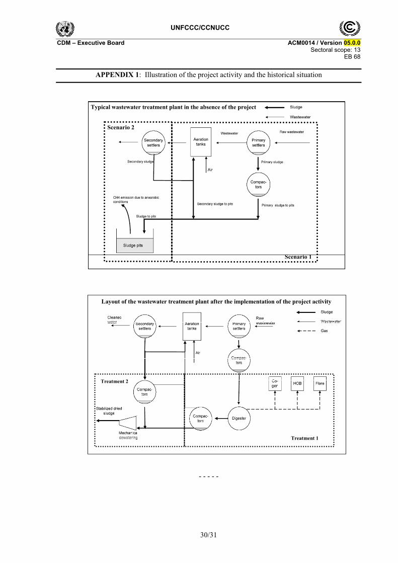
Project participants should document in the CDM-PDD which scenario applies and clearly describe the situation before and after the start of implementation of the project activity, preferably by providing similar diagrams as contained in appendix 1, which provides an example for application of Scenario 2.
The following applicability conditions are for all scenarios:
The average depth of the open lagoons or sludge pits in the baseline scenario is at least 1m;4
The residence time of the organic matter in the open lagoon or sludge pit system should be at least 30 days;5
3 Emission reductions are not claimed for both methane avoidance and biogas generation from the solid
materials. 4 In particular, loading in the wastewater streams has to be high enough to assure that the lagoon develops an
anaerobic bottom layer and that algal oxygen production can be ruled out. For project activities implemented in Greenfield facilities, the depth should be based on the design of the baseline lagoon as explained in the section “Identification of alternative scenarios”.
5 In case of an existing open lagoon in the baseline scenario the residence time of the organic matter in the lagoon should be verified based on historical data available. In the case where the baseline is a new to be built anaerobic lagoon, the residence time should be based on the design of the baseline lagoon as explained in the section “Identification of alternative scenarios”.

UNFCCC/CCNUCC CDM – Executive Board ACM0014 / Version 05.0.0
Sectoral scope: 13 EB 68
4/31
Inclusion of solid materials in the project activity is only applicable where: (i) Such solid materials are generated by the industrial facility producing the wastewater; and (ii) The solid materials would be generated both in the project and in the baseline scenario;
The sludge produced during the implementation of the project activity is not stored onsite before land application to avoid any possible methane emissions from anaerobic degradation.
II. BASELINE METHODOLOGY
Project boundary
The spatial extent of the project boundary includes:
The site where the wastewater is treated in both the baseline and the project scenario;
The sites where any sludge/dewatered wastewater is applied to lands;
Any on-site power plants that supply electricity to the wastewater or sludge treatment system;
Any on-site facilities to generate heat that is used by the wastewater or sludge treatment systems;
If applicable, the anaerobic digester, the power and/or heat generation equipment and/or the flare installed under the project activity;
If applicable, any dewatering system installed under the project activity;
If grid electricity is displaced from electricity generation with biogas from an aerobic digester: the power plants connected to the grid, with the geographical boundary as specified in the latest approved version of the “Tool to calculate the emission factor for an electricity system”.
The emission sources included in the project boundary are described in Table 2 below.
Table 2: Emission sources included and excluded from the project boundary
Source Gas Included? Justification/Explanation CH4 Yes Main source of emissions N2O No Excluded for simplification
Wastewater treatment processes or sludge disposal
CO2 No CO2 emissions from the decomposition of organic waste are not accounted for
CO2 Yes Electricity may be consumed for the operation of the wastewater or sludge treatment system in the baseline scenario
CH4 No Excluded for simplification
Electricity consumption / generation
N2O No Excluded for simplification CO2 Yes On-site thermal energy generation could be displaced
by the project activity CH4 No Excluded for simplification
Bas
elin
e
Thermal energy generation
N2O No Excluded for simplification

UNFCCC/CCNUCC CDM – Executive Board ACM0014 / Version 05.0.0
Sectoral scope: 13 EB 68
5/31
Source Gas Included? Justification/Explanation CH4 Yes Main source of emissions CO2 No CO2 emissions from the decomposition of organic
waste are not accounted for
Wastewater treatment processes or sludge treatment process
N2O Yes In case of projects that involve land application of sludge
CO2 Yes May be an important emission source CH4 No Excluded for simplification
On-site electricity use
N2O No Excluded for simplification
CO2 Yes May be an important emission source
CH4 No Excluded for simplification
Pro
ject
Act
ivit
y
On-site fossil fuel consumption
N2O No Excluded for simplification
Procedure for the identification of the most plausible baseline scenario
Project participants shall determine the most plausible baseline scenario through the application of the following steps:
Step 1: Identification of alternative scenarios
Depending on the type of a project activity (i.e. whether Scenario 1 or 2 applies, whether wastewater is treated in anaerobic digester or applied after dewatering, whether electricity is generated, etc.), project participants shall identify realistic and credible alternatives with regard to the possible scenarios that would occur in the absence of the project activity. Make sure that all scenarios include the proposed project activity not being registered under the CDM.
For all project configurations, plausible alternative scenarios for the treatment of wastewater (W) should be determined. These may include, but are not limited to, the following:
W1: The use of open lagoons for the treatment of the wastewater;
W2: Direct release of wastewater to a nearby water body;
W3: Aerobic wastewater treatment facilities (e.g. activated sludge or filter bed type treatment);
W4: Anaerobic digester with methane recovery and flaring;
W5: Anaerobic digester with methane recovery and utilization for electricity or heat generation;
W6: Wastewater is directed to land application without dewatering;
W7: Wastewater is dewatered and directed to land application/used as fuel in energy applications.

UNFCCC/CCNUCC CDM – Executive Board ACM0014 / Version 05.0.0
Sectoral scope: 13 EB 68
6/31
For project activities implemented in Greenfield facilities, the specifications of the W1 scenario shall be defined following four steps:
(a) Define several lagoon design options for the particular wastewater stream that meet the relevant regulations and take into consideration local conditions (e.g. environmental legislation, ground water table, land requirement, temperature). Design specifications shall include average depth and surface area of the lagoon, electricity consumption retention time of the organic matter and effluent flows as well as any other key parameters. Document the different design options in a transparent manner and provide transparent and documented evidence of key assumptions and data used, and offer conservative interpretations of this evidence;
(b) Carry out an economic assessment of the identified options, as per the guidance under Step 4 below. Choose the least cost lagoon design option from the options defined in Step 1 taking into account all relevant local conditions (e.g. land requirements, land prices, ground water level). If several options with comparably low costs exist, choose the one with the lowest lagoon depth as the baseline lagoon design;
In case of Scenario 2, plausible alternative scenarios for the treatment of sludge (S) should be determined. These may include, but are not limited to, the following:
S1: Disposal of sludge in sludge pits under clearly anaerobic conditions;
S2: Land application of the sludge;
S3: Landfilling;
S4: Composting;
S5: Aerobic composting;
S6: Mineralization.
If the project activity includes electricity generation with biogas from a new anaerobic digester, plausible alternative scenarios for the generation of electricity should be determined. These may include, but are not limited to, the following:
E1: Power generation using fossil fuels in a captive power plant;
E2: Electricity generation in the grid;
E3: Electricity generation using renewable sources.
If the project activity includes heat generation with biogas from a new anaerobic digester, plausible alternative scenarios for the generation of heat should be determined. These may include, but are not limited to, the following:
H1: Co-generation of heat using fossil fuels in a captive cogeneration power plant;
H2: Heat generation using fossil fuels in a boiler;
H3: Heat generation using renewable sources.
In case of Scenario 1, plausible alternative scenarios for the treatment of solid materials (SM), if applicable, should be determined. These may include, but not limited to, the following:
SM1: The solid materials are dumped or left to decay under anaerobic or aerobic conditions;
SM2: The solid materials are used as animal fodder;

UNFCCC/CCNUCC CDM – Executive Board ACM0014 / Version 05.0.0
Sectoral scope: 13 EB 68
7/31
SM3: The solid materials are burnt in an uncontrolled manner without utilizing it for energy purposes;
SM4: The solid materials are burnt for energy purposes.
The suggested list of alternatives is only indicative. Project participants may propose other plausible alternatives and/or eliminate some of the ones listed above, based on documented evidence.
Identify realistic and credible combinations of scenarios for wastewater treatment (W) and, where applicable, the treatment of sludge (S), the generation of electricity (E), the generation of heat (H) and the treatment of solid materials (SM). These combinations should be considered in the next steps.
Step 2: Eliminate alternatives that are not complying with applicable laws and regulations
Eliminate alternatives that are not in compliance with all applicable legal and regulatory requirements. Apply Sub-step 1b of the latest version of the “Tool for the demonstration and assessment of additionality” agreed by the Board.
Step 3: Eliminate alternatives that face prohibitive barriers
Scenarios that face prohibitive barriers should be eliminated by applying Step 3 of the latest version of the “Tool for the demonstration and assessment of additionality” agreed by the Board.
If only one alternative remains, this can be considered the baseline. If more than one alternative remains, proceed to Step 4.
Step 4: Compare economic attractiveness of remaining alternatives
Compare the economic attractiveness without revenues from CERs for all alternatives that are remaining by applying Step 2 of the latest approved version of the “Tool for the demonstration and assessment of additionality”. In applying the investment analysis, the IRR should be used as indicator. The following parameters should explicitly be documented:
Land cost;
Engineering, procurement and construction cost;
Labour cost;
Operation and maintenance cost;
Administration cost;
Fuel cost;
Capital cost and interest;
Revenue from electricity sales;
All other costs of implementing the technology of the each alternative option;
All revenues generated by the implementation of the proposed technology except for carbon credits revenues (including energy savings due to captive use of biogas as fuel for either electricity or heat generation at the project site, revenue on account of avoided water consumption, fossil fuel replacement, sale of concentrated solids as fertilizers etc.).

UNFCCC/CCNUCC CDM – Executive Board ACM0014 / Version 05.0.0
Sectoral scope: 13 EB 68
8/31
In the case that there are several alternatives remaining after Step 2 and that at least two alternatives are associated with costs, an investment comparison analysis should be conducted. In doing so, compare the IRR of the different alternatives and select the most cost-effective alternative (i.e. with the highest IRR) as the baseline scenario. Include a sensitivity analysis applying Sub-step 2d of the latest version of the “Tool for the demonstration and assessment of additionality” agreed by the Board. The investment comparison analysis provides a valid argument that the most cost-effective scenario is the baseline scenario if it consistently supports (for a realistic range of assumptions) this conclusion. In case the sensitivity analysis is not fully conclusive, select the baseline scenario alternative with least emissions among the alternatives that are the most economically attractive according to the investment analysis and the sensitivity analysis.
In the case the project undertaken without being registered as a CDM project activity is the only remaining alternative with associated costs, a benchmark analysis is to be used to demonstrate its profitability or non-profitability. If the project is profitable, it is to be considered as the baseline scenario. If not, the continuation of the current situation is the baseline.
The methodology is only applicable if it can be demonstrated that the baseline scenario corresponds to the scenario described in Table 1 above and if the following baseline scenarios are most likely:
For Scenario 1: W1 for the treatment of wastewater and, if applicable, E1/E2 for the generation of electricity and SM1/SM2/SM3 for the solid materials;
For Scenario 2: W3 for the treatment of wastewater, S1 for the use of the sludge and, if applicable, E1/E2 for the generation of electricity.
Additionality
Use the latest version of the “Tool for the demonstration and assessment of additionality” agreed by the Board. In doing so, ensure consistency with the guidance provided in the “Procedure for the identification of the most plausible baseline scenario”. If the baseline scenario of a project activity implemented in a Greenfield facility is the use of open lagoons, additionality assessment shall be conducted on the basis of the lagoon parameters defined in Step 1 of the “Procedure for the identification of the most plausible baseline scenario”.
Baseline emissions
Baseline emissions are estimated as follows:
yHG,yEL,yCH4,y BEBEBEBE (1)
Where:
yBE = Baseline emissions in year y (tCO2e/yr)
yCH4,BE = Methane emissions from anaerobic treatment of the wastewater in open lagoons (Scenario 1) or the anaerobic treatment of sludge in sludge pits (Scenario 2) in the absence of the project activity in year y (tCO2e/yr)
yEL,BE = CO2 emissions associated with electricity generation that is displaced by the project activity and/or electricity consumption in the absence of the project activity in year y (tCO2/yr)
yHG,BE = CO2 emissions associated with fossil fuel combustion for heating equipment that is displaced by the project in year y (tCO2/yr)

UNFCCC/CCNUCC CDM – Executive Board ACM0014 / Version 05.0.0
Sectoral scope: 13 EB 68
9/31
Baseline emissions are calculated in three steps, as follows:
Step 1: Calculation of baseline emissions from anaerobic treatment of the wastewater or sludge;
Step 2: Calculation of baseline emissions from generation and consumption of electricity (if applicable);
Step 3: Calculation of baseline emissions from heat generation (if applicable).
Steps 2 and 3 are only applicable if electricity or heat is generated from biogas generated in the anaerobic digester.
Step 1: Calculation of baseline emissions from anaerobic treatment of the wastewater or sludge
The methodology proposes to use the minimum value between the methane produced after the implementation of the project activity and methane conversion factor method for the estimation of methane emissions from open lagoons in case of the waste water lagoons and sludge in sludge pits.
yMCFCHBE ,,4yCH4,yCH4, ;QminBE (2)
Methane produced
Projects proponent shall use Step 1” Determination of the quantity of methane produced in the digester (QCH4,y)”of the latest version of the tool “Project and leakage emissions from anaerobic digesters” to determine the amount of methane produced after the implementation of the project activity (QCH4,y).
Methane conversion factor
The baseline methane emissions from anaerobic treatment of the wastewater in open lagoons (Scenario 1) or the anaerobic treatment of sludge in sludge pits (Scenario 2) are estimated based on the chemical oxygen demand (COD) of the wastewater that would enter the lagoon or sludge in the sludge pits in the absence of the project activity (CODBL,y), the maximum methane producing capacity (Bo) and a methane conversion factor (MCFBL,y) which expresses the proportion of the wastewater that would decay to methane, as follows:
yBL,oyBL,CH4yMCF,CH4, CODBMCFGWPBE (3)
Where:
yMCF,CH4,BE = Methane emissions from anaerobic treatment of the wastewater in open lagoons (Scenario 1) or the anaerobic treatment of sludge in sludge pits (Scenario 2) in the absence of the project activity in year y (tCO2e/yr)
CH4GWP = Global Warming Potential of methane valid for the commitment period (tCO2e/tCH4)
oB = Maximum methane producing capacity, expressing the maximum amount of CH4 that can be produced from a given quantity of chemical oxygen demand (tCH4/tCOD)
yBL,MCF = Average baseline methane conversion factor (fraction) in year y, representing the fraction of (CODPJ,y x Bo) that would be degraded to CH4 in the absence of the project activity
yBL,COD = Quantity of chemical oxygen demand that would be treated in open lagoons (Scenario 1) or in sludge pits (Scenario 2) in the absence of the project activity in year y (tCOD/yr)
UNFCCC/CCNUCC CDM – Executive Board ACM0014 / Version 05.0.0
Sectoral scope: 13 EB 68
10/31
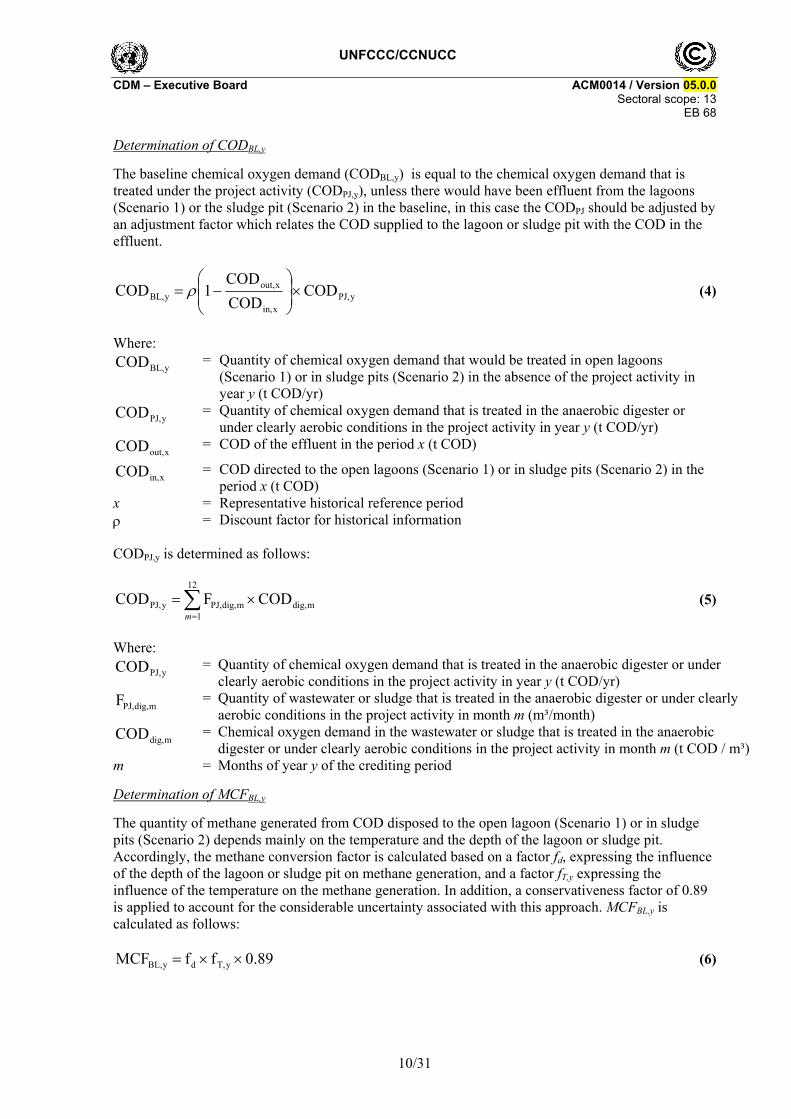
Determination of CODBL,y
The baseline chemical oxygen demand (CODBL,y) is equal to the chemical oxygen demand that is treated under the project activity (CODPJ,y), unless there would have been effluent from the lagoons (Scenario 1) or the sludge pit (Scenario 2) in the baseline, in this case the CODPJ should be adjusted by an adjustment factor which relates the COD supplied to the lagoon or sludge pit with the COD in the effluent.
yPJ,xin,
xout,yBL, COD
COD
COD1COD
(4)
Where:
yBL,COD = Quantity of chemical oxygen demand that would be treated in open lagoons (Scenario 1) or in sludge pits (Scenario 2) in the absence of the project activity in year y (t COD/yr)
yPJ,COD = Quantity of chemical oxygen demand that is treated in the anaerobic digester or under clearly aerobic conditions in the project activity in year y (t COD/yr)
xout,COD = COD of the effluent in the period x (t COD)
xin,COD = COD directed to the open lagoons (Scenario 1) or in sludge pits (Scenario 2) in the period x (t COD)
x = Representative historical reference period = Discount factor for historical information
CODPJ,y is determined as follows:
12
1mdig,mdig,PJ,yPJ, CODFCOD
m
(5)
Where:
yPJ,COD = Quantity of chemical oxygen demand that is treated in the anaerobic digester or under clearly aerobic conditions in the project activity in year y (t COD/yr)
mdig,PJ,F = Quantity of wastewater or sludge that is treated in the anaerobic digester or under clearly aerobic conditions in the project activity in month m (m³/month)
mdig,COD = Chemical oxygen demand in the wastewater or sludge that is treated in the anaerobic digester or under clearly aerobic conditions in the project activity in month m (t COD / m³)
m = Months of year y of the crediting period
Determination of MCFBL,y
The quantity of methane generated from COD disposed to the open lagoon (Scenario 1) or in sludge pits (Scenario 2) depends mainly on the temperature and the depth of the lagoon or sludge pit. Accordingly, the methane conversion factor is calculated based on a factor fd, expressing the influence of the depth of the lagoon or sludge pit on methane generation, and a factor fT,y expressing the influence of the temperature on the methane generation. In addition, a conservativeness factor of 0.89 is applied to account for the considerable uncertainty associated with this approach. MCFBL,y is calculated as follows:
0.89ffMCF yT,dyBL, (6)
UNFCCC/CCNUCC CDM – Executive Board ACM0014 / Version 05.0.0
Sectoral scope: 13 EB 68
11/31
Where:
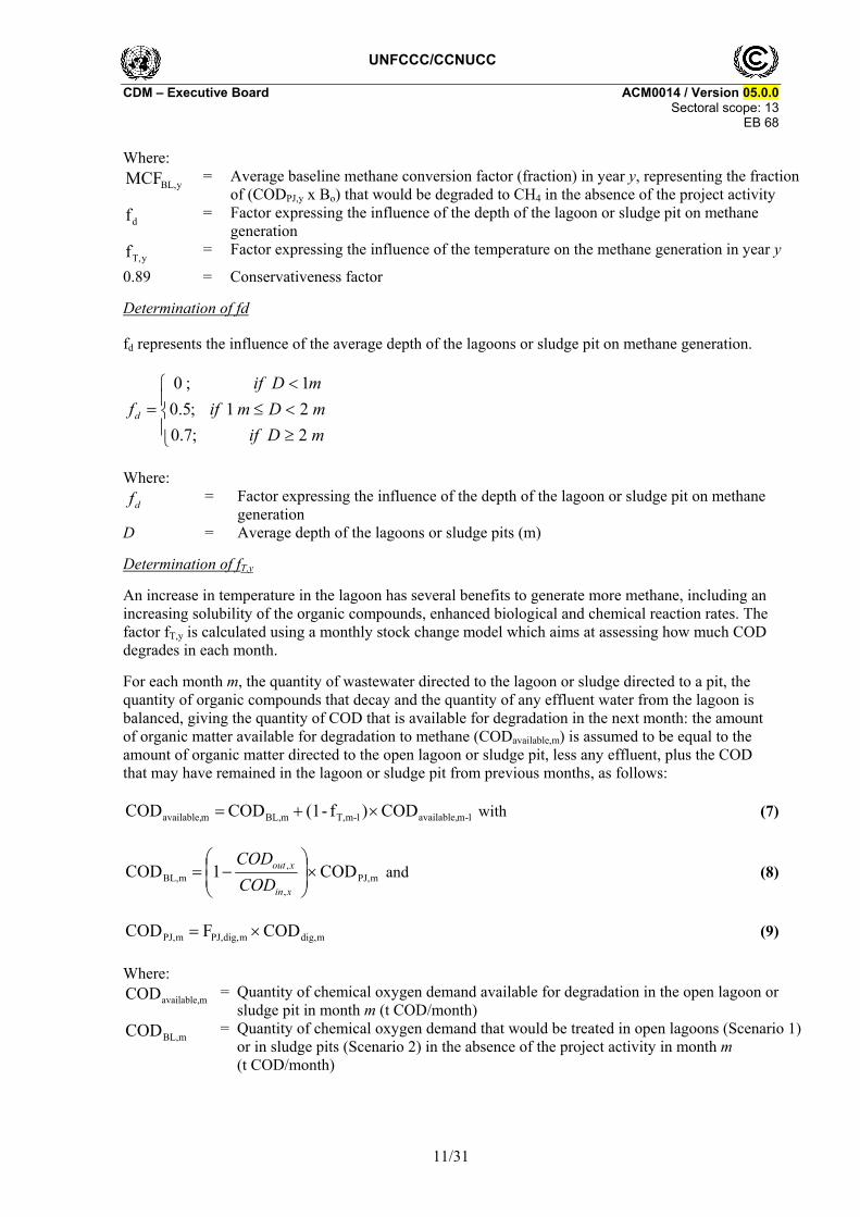
yBL,MCF = Average baseline methane conversion factor (fraction) in year y, representing the fraction of (CODPJ,y x Bo) that would be degraded to CH4 in the absence of the project activity
df = Factor expressing the influence of the depth of the lagoon or sludge pit on methane generation
yT,f = Factor expressing the influence of the temperature on the methane generation in year y
0.89 = Conservativeness factor
Determination of fd
fd represents the influence of the average depth of the lagoons or sludge pit on methane generation.
mDif
mDmif
mDif
fd
2;7.0
21;5.0
1;0
Where:
df = Factor expressing the influence of the depth of the lagoon or sludge pit on methane generation
D = Average depth of the lagoons or sludge pits (m)
Determination of fT,y
An increase in temperature in the lagoon has several benefits to generate more methane, including an increasing solubility of the organic compounds, enhanced biological and chemical reaction rates. The factor fT,y is calculated using a monthly stock change model which aims at assessing how much COD degrades in each month.
For each month m, the quantity of wastewater directed to the lagoon or sludge directed to a pit, the quantity of organic compounds that decay and the quantity of any effluent water from the lagoon is balanced, giving the quantity of COD that is available for degradation in the next month: the amount of organic matter available for degradation to methane (CODavailable,m) is assumed to be equal to the amount of organic matter directed to the open lagoon or sludge pit, less any effluent, plus the COD that may have remained in the lagoon or sludge pit from previous months, as follows:
1-mavailable,1-mT,mBL,mavailable, COD)f-(1COD COD with (7)
mPJ,,
,mBL, COD1COD
xin
xout
COD
COD and (8)
mdig,mdig,PJ,mPJ, CODFCOD (9)
Where:
mavailable,COD = Quantity of chemical oxygen demand available for degradation in the open lagoon or sludge pit in month m (t COD/month)
mBL,COD = Quantity of chemical oxygen demand that would be treated in open lagoons (Scenario 1) or in sludge pits (Scenario 2) in the absence of the project activity in month m (t COD/month)

UNFCCC/CCNUCC CDM – Executive Board ACM0014 / Version 05.0.0
Sectoral scope: 13 EB 68
12/31
mPJ,COD = Quantity of chemical oxygen demand that is treated in the anaerobic digester or under clearly aerobic conditions in the project activity in month m (t COD/month)
mdig,PJ,F = Quantity of wastewater or sludge that is treated in the anaerobic digester or under clearly aerobic conditions in the project activity in month m (m³/month)
mdig,COD = Chemical oxygen demand in the wastewater or sludge that is treated in the anaerobic digester or under clearly aerobic conditions in the project activity in month m (t COD/m³)
1-mT,f = Factor expressing the influence of the temperature on the methane generation in month m
m = Months of year y of the crediting period
xoutCOD , = COD of the effluent in the period x (t COD)
xinCOD , = COD directed to the open lagoons (Scenario 1) or in sludge pits (Scenario 2) in the period x (t COD)
x = Representative historical reference period
In case of emptying the lagoon or sludge pit, the accumulation of organic matter restarts with the next inflow and the COD available from the previous month should be set to zero. The monthly factor to account for the influence of the temperature on methane generation is calculated based on the following “van’t Hoff – Arrhenius” approach:
KTif
KTKif
KTif
m
m
m
3031
303283e
2830
f
,2
,2
T*T*R
)T-(T*E
,2
mT,m2,1
1m2,
(10)
Where:
mT,f = Factor expressing the influence of the temperature on the methane generation in month m
E = Activation energy constant (15,175 cal/mol)
mT ,2 = Average temperature at the project site in month m (K)
1T = 303.16 K (273.16 K + 30 K)
R = Ideal gas constant (1.987 cal/K mol) M = Months of year y of the crediting period
The annual value fT,y is calculated as follows:
12
1mmBL,
12
1m,mT,
yT,
COD
Cff
mavailableOD (11)
Where:
yT,f = Factor expressing the influence of the temperature on the methane generation in year y
mT,f = Factor expressing the influence of the temperature on the methane generation in month m
mavailableOD ,C = Quantity of chemical oxygen demand available for degradation in the open lagoon or sludge pit in month m (t COD/month)

UNFCCC/CCNUCC CDM – Executive Board ACM0014 / Version 05.0.0
Sectoral scope: 13 EB 68
13/31
mBL,COD = Quantity of chemical oxygen demand that would be treated in open lagoons (Scenario 1) or in sludge pits (Scenario 2) in the absence of the project activity in month m (t COD/month)
m = Months of year y of the crediting period
Step 2: Baseline emissions from generation and/or consumption of electricity
In this step, baseline emissions from the following sources are estimated:
Baseline emissions from consumption of electricity associated with the treatment of wastewater (Scenario 1) or the treatment of sludge (Scenario 2);
If electricity is generated with biogas from a new anaerobic digester under the project activity: baseline emissions from the generation of electricity in the grid (E2) and/or with a captive fossil fuel fired power plant (E1) in the absence of the electricity generation with biogas.
As a simplification, project participants may neglect one or both emission sources. Baseline emissions from the generation and/or consumption of electricity are calculated as follows:
yEL,BL,yPJ,BLyEL, EFEGECBE (12)
Where:
yEL,BE = CO2 emissions associated with electricity generation that is displaced by the project activity and/or electricity consumption in the absence of the project activity in year y (tCO2/yr)
BLEC = Annual quantity of electricity that would be consumed in the absence of the project activity for the treatment of the wastewater (Scenario 1) or the treatment of the sludge (Scenario 2) (MWh/yr)
yPJ,EG = Net quantity of electricity generated in year y with biogas from the new anaerobic biodigester (MWh/yr)
yEL,BL,EF = Baseline emission factor for electricity generated and/or consumed in the absence of the project activity in year y (tCO2/MWh)
Determination of EFBL,EL,y
The determination of EFBL,EL,y depends on the baseline scenario and the configuration at the project site.
The grid emission factor, calculated using the latest version of the “Tool to calculate the emission factor for an electricity system”, should be used if the baseline scenario for displacement of electricity generated with biogas from the anaerobic digester is E2 or, in the case that no electricity is generated at the project site using fossil fuels in year y.
ygrid,yEL,BL, EF EF (13)
In all other cases, the lower emission factor between the grid emission factor, calculated using the latest version of the “Tool to calculate the emission factor for an electricity system”, and the emission factor of a captive power plant should be used as a conservative simplification, as follows:
8.0;EF ,yEL,BL, ygridEFMIN (14)

UNFCCC/CCNUCC CDM – Executive Board ACM0014 / Version 05.0.0
Sectoral scope: 13 EB 68
14/31
Where:
yEL,BL,EF = Baseline emission factor for electricity generated and/or consumed in the absence of the project activity in year y (tCO2/MWh)
ygridEF , = Grid emission factor in year y (tCO2/MWh)
The emission factor of 0.8 tCO2/MWh represents the case of producing electricity using a diesel engine.
Step 3: Baseline emissions from the generation of heat
This step is applicable if the biogas captured from the new anaerobic digester is utilized in the project scenario for heat generation. If the baseline Scenarios H1 or H3 apply, BEHG,y = 0.6 If Scenario H2 applies, fossil fuels from the generation of heat in boilers are displaced and baseline emissions are calculated as follows:
boilerBL
boilerFFCOyPJyHG
EFHGBE
,
,,2,,
(15)
Where:
yHGBE , = CO2 emissions associated with fossil fuel combustion for heating equipment that is displaced by the project in year y (tCO2/yr)
yPJHG , = Net quantity of heat generated in year y with biogas from the new anaerobic digester (GJ)
boilerFFCOEF ,,2 = CO2 emission factor of the fossil fuel type used in the boiler for heat generation in the absence of the project activity (tCO2/GJ)
boilerBL, = Efficiency of the boiler that would be used for heat generation in the absence of the project activity
Determination of EFCO2,FF,boiler
For existing facilities:
Project participants should choose the fossil fuel with the lowest emission factor that was used in the industrial facility that generates de wastewater for heating purposes before the implementation of the project activity the year prior the implementation of the project activity.
For Greenfield facilities:
Project participants shall use natural gas as the baseline fossil fuel if this resource is available in the region. Otherwise,
Project participants should identify what is the most common fuel used in industrial facilities and use it as baseline fuel. Detailed justifications shall be provided and documented in the CDM-PDD for the selected baseline fuel.
6 In case of cogeneration in the absence of the project activity (H1), the emission reductions from using the
biogas in a cogeneration plant are already reflected in Step 2.

UNFCCC/CCNUCC CDM – Executive Board ACM0014 / Version 05.0.0
Sectoral scope: 13 EB 68
15/31
Determination of BL,boiler
Project participants should use the latest version of the “Tool to determine the baseline efficiency of thermal or electric energy generation systems” to determine the efficiency of the boiler. Parameter BL,boiler corresponds to parameter in the tool.
Project emissions
Emissions attributed to the project activity depend on which scenario in Table 1 applies and the configuration of the project activity:
(a) In the case of project activities that introduce an anaerobic digester for the treatment of wastewater, solid materials or sludge. Use the latest approved version of the tool “Project and leakage emissions from anaerobic digesters” to calculate project and leakage emissions;
(b) In the case of project activities that introduce a treatment of sludge or land application of wastewater. Estimate methane and nitrous oxide emissions from land application of sludge following step (i) below;
(c) In the case of project activities where wastewater is dewatered and directed to land application. Estimate methane and nitrous oxide emissions from land application of wastewater following step (ii) below;
Project participants should document and justify in the CDM-PDD which emission sources are applicable in the context of their project activity.
(i) Project emissions from land application of sludge
This emission source is only applicable if under the project activity sludge is applied on lands. For conservativeness, an MCF of 0.05 is to be used to estimate possible methane emissions from the land application treatment process to account for any possible anaerobic pockets. These emissions are to be estimated from the following equations:
N2O,,2,,4,,,yLA,sludge, GWPPE sludgeLAONyLAsludgeCHLAsludgeoyLAsludge EFNGWPMCFBCOD (16)
with
12
1mLA,COD,sludge,mLA,yLA,sludge, wSCOD
m
and (17)
12
1msludge,N,mLA,yLA,sludge, wSN
m
(18)
Where:
yLA,sludge,PE = Project emissions from land application of sludge in year y (tCO2e/yr)
yLAsludgeCOD ,, = Chemical oxygen demand (COD) of the sludge applied to land after the dewatering process in year y (tCOD/yr)
oB = Maximum methane producing capacity, expressing the maximum amount of CH4 that can be produced from a given quantity of chemical oxygen demand (tCH4/tCOD)
UNFCCC/CCNUCC CDM – Executive Board ACM0014 / Version 05.0.0
Sectoral scope: 13 EB 68
16/31
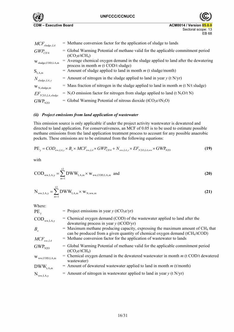
LAsludgeMCF , = Methane conversion factor for the application of sludge to lands
4CHGWP = Global Warming Potential of methane valid for the applicable commitment period (tCO2e/tCH4)
mLA,COD,sludge,w = Average chemical oxygen demand in the sludge applied to land after the dewatering process in month m (t COD/t sludge)
mLA,S = Amount of sludge applied to land in month m (t sludge/month)
yLAsludgeN ,, = Amount of nitrogen in the sludge applied to land in year y (t N/yr)
msludge,N,w = Mass fraction of nitrogen in the sludge applied to land in month m (t N/t sludge)
sludgeLAONEF ,,2 = N2O emission factor for nitrogen from sludge applied to land (t N2O/t N)
N2OGWP = Global Warming Potential of nitrous dioxide (tCO2e/tN2O)
(ii) Project emissions from land application of wastewater
This emission source is only applicable if under the project activity wastewater is dewatered and directed to land application. For conservativeness, an MCF of 0.05 is to be used to estimate possible methane emissions from the land application treatment process to account for any possible anaerobic pockets. These emissions are to be estimated from the following equations:
N2O,,2,,4,,,y GWPPE wwLAONyLAwwCHLAwwoyLAww EFNGWPMCFBCOD (19)
with
12
1mLA,COD,ww,mLA,yLA,ww, wDWWCOD
m
and (20)
12
1mww,N,mLA,yLA,ww, wDWWN
m
(21)
Where:
yPE = Project emissions in year y (tCO2e/yr)
yLA,ww,COD = Chemical oxygen demand (COD) of the wastewater applied to land after the dewatering process in year y (tCOD/yr)
oB = Maximum methane producing capacity, expressing the maximum amount of CH4 that can be produced from a given quantity of chemical oxygen demand (tCH4/tCOD)
LAwwMCF , = Methane conversion factor for the application of wastewater to lands
N2OGWP = Global Warming Potential of methane valid for the applicable commitment period (tCO2e/tCH4)
mLA,COD,ww,w = Chemical oxygen demand in the dewatered wastewater in month m (t COD/t dewatered wastewater)
mLA,DWW = Amount of dewatered wastewater applied to land in month m (t/month)
yLA,ww,N = Amount of nitrogen in wastewater applied to land in year y (t N/yr)

UNFCCC/CCNUCC CDM – Executive Board ACM0014 / Version 05.0.0
Sectoral scope: 13 EB 68
17/31
mww,N,w = Mass fraction of nitrogen in the wastewater applied to land in month m (t N/t dewatered wastewater)
wwLAONEF ,,2 = N2O emission factor for nitrogen from wastewater applied to land (t N2O/t N)
N2OGWP = Global Warming Potential of nitrous dioxide (tCO2e/tN2O)
Leakage emissions
In the case of project activities that introduce an anaerobic digester for the treatment of wastewater, solid materials or sludge. Use the latest approved version of the tool “Project and leakage emissions from anaerobic digesters” to calculate leakage emissions.
Additionally leakage emissions are also calculated for Scenario 1 type projects that include the treatment of solid materials in the digester in the project activity, and identified baseline scenario for the treatment of solid materials in the “Procedure for the identification of the most plausible baseline scenario” is SM2: the solid materials are used as animal fodder.
In such case, the potential source of leakage emission is the CO2 emissions related to the production of additional animal fodder (or feed) that would be required in the project scenario due to the diversion of solid materials that were used as animal fodder in the baseline scenario, as a result of the project activity.
For this purpose, project participants shall assess the supply situation for the types of solid materials (suitable for animal fodder) in the region. Project participants may, however, rule out the leakage emissions, if they demonstrate that the use of the solid materials in the project activity does not result in CO2 emissions elsewhere for the production of additional animal fodder, by one of the options below: L1: Demonstrate that there is an abundant surplus of the solid materials in the region of the project
activity which are not utilized. For this purpose, demonstrate that the quantity of available solid materials in the region is at least 25% larger than the quantity that is utilized for animal fodder;
L2: Demonstrate that suppliers of the solid materials in the region of the project activity are not able to sell all of their solid materials. For this purpose, project participants shall demonstrate that both project entity as well as a representative sample of producers of the same type of solid materials in the region, had a surplus of these solid materials (e.g. at the end of the period during which solid materials are sold), which they could not sell and which is not utilized.
When project participants wish to use approaches L1 or L2 to rule out leakage emissions, they shall clearly define the geographical boundary of the region and document it in the CDM-PDD. In defining the geographical boundary of the region, project participants should take the usual distances for animal fodder transports into account, i.e. if animal fodder is transported up to 50 km, the region may cover a radius of 50 km around the project activity. In any case, the region should cover a radius around the project activity of at least 20 km but not more than 200 km.
If project participants are not able to rule out the leakage emissions using one of the approaches above, a leakage penalty shall be applied. This leakage penalty shall be calculated for each year y as follows:
k,,,,2y NCV LE ykPJk
LEkCO SMEF and (22)
i,,2 EF i
iLEkCO fEF (23)

UNFCCC/CCNUCC CDM – Executive Board ACM0014 / Version 05.0.0
Sectoral scope: 13 EB 68
18/31
Where:
yLE = Leakage emissions during the year y (tCO2/yr)
LEkCOEF ,,2 = CO2 emission factor of production of animal fodder that is used to replace the solid materials type k (tCO2/GJ)
ykPJSM ,, = Quantity of solid materials type k that are displaced as animal fodder as a result of the project activity during the year y (tons of dry matter)
k = Types of solid materials for which leakage effects could not be ruled out with one of the approaches L1 or L2 above
kNCV = Net calorific value of the solid materials type k (GJ/ton)
if = Fraction of total calorific value of animal feed type i, compared to the total calorific value of all animal feed, which is used to replace the solid materials (%)
iEF = Specific production emission factor of type of animal feed i which is used to replace the solid materials (tCO2/GJ)
i = Types of different animal feeds which are used to replace the solid materials
Alternatively, given the potential complexity of the above procedure, the leakage penalty may be calculated by applying a simple yet conservative alternative:
DLE ,,y k
ykPJSM (24)
Where:
yLE = Leakage emissions during the year y (tCO2/yr)
ykPJSM ,, = Quantity of solid materials type k that are displaced as animal fodder as a result of the project activity during the year y (tons of dry matter)
D = Default value of 1 tCO2/ton of dry matter
Note that the default value can only be used in case the production of animal fodder in the region does not have an impact on deforestation.
Emission reductions
Emission reductions for any given year of the crediting period are obtained by subtracting project emissions from baseline emissions:
yyyy LEPEBEER (25)
Where:
yER = Emissions reductions of the project activity in year y (tCO2e/year)
yBE = Baseline emissions in year y (tCO2e/year)
yPE = Project emissions in year y (tCO2e/year)
yLE = Leakage emissions in year y (tCO2e/year)
Changes required for methodology implementation in 2nd and 3rd crediting periods
Consistent with guidance by the Board, project participants shall use the latest version of the tool “Assessment of the validity of the original/current baseline and update of the baseline at the renewal of the crediting period”.

UNFCCC/CCNUCC CDM – Executive Board ACM0014 / Version 05.0.0
Sectoral scope: 13 EB 68
19/31
Project activity under a programme of activities
In addition to the requirements set out in the latest approved version of the “Standard for demonstration of additionality, development of eligibility criteria and application of multiple methodologies for programme of activities”, the following shall be applied for the use of this methodology in a project activity under a programme of activities (PoAs).
The PoA may consist of one or several types of CPAs. CPAs are regarded to be of the same type if they are similar with regard to the demonstration of additionality, emission reduction calculations and monitoring. The CME shall describe in the CDM-PoA-DD for each type of CPAs separately:
(a) Eligibility criteria for CPA inclusion used for each type of CPAs. In case of combinations of the types of use of the captured biogas in one CPA, the eligibility criteria shall be defined for each type of use of biogas separately;
(b) Emission reduction calculations for each type of CPAs;
(c) Monitoring provisions for each type of CPAs.
The CME shall describe transparently and justify in the CDM-PoA-DD which CPAs are regarded to be of the same type. CPAs shall not be regarded to be of the same type if one of the following conditions is different:
(a) The baseline scenario with regard to any of the following aspects:
(i) Use of open lagoons with anaerobic conditions for wastewater treatment;
Treatment options for solid materials;
(ii) Use of anaerobic wastewater treatment facilities. Sludge is generated from primary and/or secondary settlers and directed to sludge pits with anaerobic conditions;
(b) The project activity with regard to any of the following aspects:
1. The project activity is wastewater treatment with an anaerobic digester.
(a) The captured biogas is used for in one of the following ways:
(i) Flaring;
(ii) Heat generation;
(iii) Electricity generation;
(iv) Feeding biogas into a natural gas network;
(v) Combinations of any of the above;
(b) The residual sludge from the anaerobic digester is directed to:
(i) Open lagoons;
(ii) Dewatering and land application.
2. Wastewater is treated at the wastewater treatment facilities of a wastewater treatment plant.
(a) The sludge generated from primary and/or secondary settlers is treated in the following ways:
(b) The sludge is treated in a new anaerobic digester that enables the use of captured biogas for:

UNFCCC/CCNUCC CDM – Executive Board ACM0014 / Version 05.0.0
Sectoral scope: 13 EB 68
20/31
(i) Flaring;
(ii) Heat generation;
(iii) Electricity generation;
(iv) Feeding biogas into a natural gas network;
(v) Combination of any of the above;
(c) The residual sludge from the digester is directed to:
(i) Open lagoons;
(ii) Dewatering and land application.
(d) The sludge is treated under aerobic conditions through wastewater dewatering and directing to land application;
(i) The legal and regulatory framework
(ii) Type of wastewater (e.g., COD ranges)
(iii) Type of industry generating wastewater (e.g., pulp and paper industry, food industry, etc.
For example, one type of CPAs may be characterized by the following combinations. The baseline scenario is the use of an anaerobic lagoon for wastewater treatment. Under the project activity, an anaerobic digester is used. The biogas from the digester is used to produce heat. The residual sludge from the anaerobic digester is dewatered and applied to land. Another type of CPAs is characterized by the following combinations. The baseline scenario is the use of the anaerobic lagoon for wastewater treatment. Under the project activity, the anaerobic digester is used for wastewater treatment. The biogas from the digester is used to produce electricity. The residual sludge from the anaerobic digester is treated in open lagoons.
When defining eligibility criteria for CPA inclusion for a distinct type of CPAs, the CME shall consider relevant technical and economic parameters, such as:
(a) Ranges of design specifications of baseline and project wastewater treatment units (e.g., a range of average depths and surface areas of lagoons, electricity consumption, residence time of the organic matter and effluent adjustment factor);
(b) Local conditions (temperature);
(c) Ranges of capacity of biogas production;
(d) Ranges of costs (capital investment in Greenfield wastewater treatment facility, operating and maintenance costs, etc.);
(e) Ranges of revenues (income from electricity, heat or biogas sale, subsidies/fiscal incentives, ODA).
The eligibility criteria related to the costs and revenues parameters shall be updated every two years in order to correctly reflect the technical and market circumstances of a CPA implementation
In case the PoA contains several types of CPAs, the actual CPA-DD submitted for the purpose of registration of the PoA shall contain all information required as per the latest approved version of the

UNFCCC/CCNUCC CDM – Executive Board ACM0014 / Version 05.0.0
Sectoral scope: 13 EB 68
21/31
“Guidelines for completing the component project activity design document form” for each type of actual CPA, to be validated by a DOE and submitted for the registration to the Board.
Data and parameters not monitored
In addition to the data and parameters listed below, the guidance on “data and parameters not monitored” in all tools to which this methodology refers applies. Data / Parameter: CODout,x
CODin,x Data unit: t COD Description: COD of the effluent in the period x
COD directed to the open lagoons (Scenario 1) or in sludge pits (Scenario 2) in the period x
Source of data: For existing plants: (a) If there is no effluent: CODout,x = 0; (b) If there is effluent:
One year of historical data should be used; or If one year data is not available then x represents a measurement
campaign of at least 10 days to the COD inflow (CODin,x) and COD outflow (CODout,x) from the lagoon or sludge pit.
For Greenfield projects: (a) Use the design COD inflow for COD in and the design effluent COD
flow for COD out corresponding to the design features of the lagoon system identified in the procedure for the selection of the baseline scenario
Measurement procedures (if any):
For the measurement campaign of at least 10 days: The measurements should be undertaken during a period that is representative for the typical operation conditions of the plant and ambient conditions of the site (temperature)
Any comment: Data / Parameter: x Data unit: Time Description: Representative historical reference period Source of data: For existing plants:
(a) x should represents one year of historical data; (b) If one year data is not available then x represents a measurement
campaign of at least 10 days. For Greenfield projects this parameter is not relevant
Measurement procedures (if any):
Any comment: Data / Parameter: Data unit: Description: Discount factor for historical information

UNFCCC/CCNUCC CDM – Executive Board ACM0014 / Version 05.0.0
Sectoral scope: 13 EB 68
22/31
Source of data: For existing plants: If one year of historical data is available =1; If a measurement campaign of at least 10 days is available =0.89.
For Greenfield projects: =1 Measurement procedures (if any):
The value of 0.89 for the case where there is no one year historical data is to account for the uncertainty range (of 30% to 50%) associated with this approach as compared to one-year historical data
Any comment: Data / Parameter: Bo Data unit: tCH4/tCOD Description: Maximum methane producing capacity, expressing the maximum amount of
CH4 that can be produced from a given quantity of chemical oxygen demand (COD)
Source of data: 2006 IPCC Guidelines Measurement procedures (if any):
No measurement procedures. The default IPCC value for Bo is 0.25 kg CH4/kg COD. If the methodology is used for wastewater containing materials not akin to simple sugars, a CH4 emissions factor different from 0.21 tCH4/tCOD has to be estimated and applied
Any comment: Taking into account the uncertainty of this estimate, project participants should use a value of 0.21 kg CH4/kg COD as a conservative assumption for Bo
Data / Parameter: D Data unit: m Description: Average depth of the lagoons or sludge pits Source of data: For existing plants: conduct measurements.
For project activities implemented in Greenfield facilities: as per the baseline lagoon design as identified in Step 1 of the section “Procedure for the identification of the most plausible baseline scenario Identification of alternative scenarios”
Measurement procedures (if any):
Determine the average depths of the whole lagoon/sludge pit under normal operating conditions
Any comment: - Data / Parameter: ECBL Data unit: MWh/yr Description: Annual quantity of electricity that would be consumed in the absence of the
project activity for the treatment of the wastewater (Scenario 1) or the treatment of the sludge (Scenario 2)
Source of data: In case of existing plants: Average yearly electricity consumption of the most recent three years prior
to the implementation of the project activity. In case of project activities implemented in Greenfield facilities: Technical specifications according to the baseline lagoon or sludge pit
identified in Step 1 of the section “Procedure for the identification of the most plausible baseline scenario”

UNFCCC/CCNUCC CDM – Executive Board ACM0014 / Version 05.0.0
Sectoral scope: 13 EB 68
23/31
Measurement procedures (if any):
Historical records must correspond to measurements whereby electricity meters undergo maintenance/calibration subject to appropriate industry standards. The accuracy of the meter readings will be verified by receipts issued by the purchasing power company. Uncertainty of the meters to be obtained from the manufacturers
Any comment: - Data / Parameter: EFCO2,FF,boiler Data unit: tCO2/GJ Description: CO2 emission factor of the fossil fuel type used in the boiler for heat generation
in the absence of the project activity Source of data: Actual measured or local data is to be used. If not available, regional data should
be used and, in its absence, IPCC default values can be used from the most recent version of IPCC Guidelines for National Greenhouse Gas Inventories
Measurement procedures (if any):
-
Any comment: If the measurement results differ significantly from previous measurements or other relevant data sources, conduct additional measurements. Double-checked against IPCC defaults (for consistency) if data is local or regional
Data / Parameter: EFN2O,LA,sludge Data unit: t N2O/t N Description: N2O emission factor for nitrogen from sludge applied to land Source of data: Stehfest, E. and Bouwman, A.F. N2O and NO emission from agricultural fields
and soils under natural vegetation: summarizing available measurement data and modelling of global annual emissions. Nutr. Cycl. 29 Agroecosyst., in press. The average emission factor used is 0.01 kg N2O-N / kg N (= 0.016 kg N2O / kg N)
Measurement procedures (if any):
No measurement procedures. Value to be applied: 0.016
Any comment: Applicable if sludge is applied on lands under the project activity Data / Parameter: EFN2O,LA,ww Data unit: t N2O/t N Description: N2O emission factor for nitrogen from wastewater applied to land Source of data: Stehfest, E. and Bouwman, A.F. N2O and NO emission from agricultural fields
and soils under natural vegetation: summarizing available measurement data and modelling of global annual emissions. Nutr. Cycl. 29 Agroecosyst., in press. The average emission factor used is 0.01 kg N2O-N/kg N (= 0.016 kg N2O/kg N)
Measurement procedures (if any):
No measurement procedures. Value to be applied: 0.016
Any comment: Applicable if sludge is applied on lands under the project activity Data / Parameter: MCFsludge,LA Data unit: - Description: Methane conversion factor for the application of sludge to lands
UNFCCC/CCNUCC CDM – Executive Board ACM0014 / Version 05.0.0
Sectoral scope: 13 EB 68
24/31
Source of data: - Measurement procedures (if any):
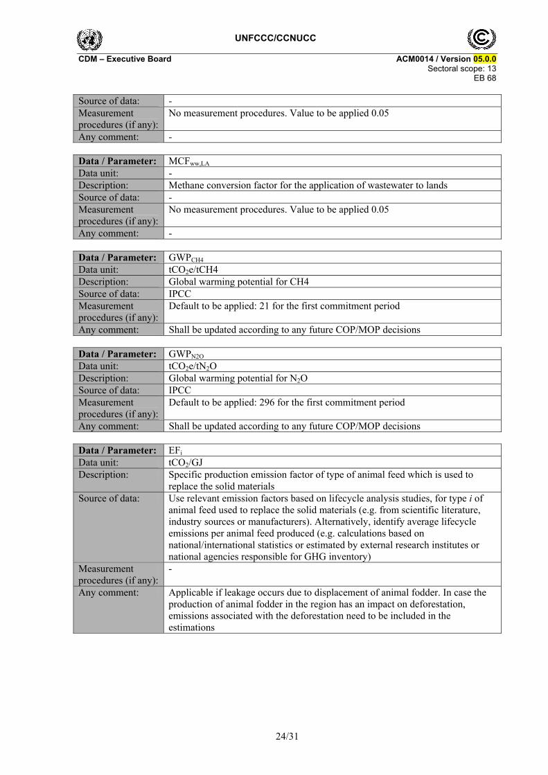
No measurement procedures. Value to be applied 0.05
Any comment: - Data / Parameter: MCFww,LA Data unit: - Description: Methane conversion factor for the application of wastewater to lands Source of data: - Measurement procedures (if any):
No measurement procedures. Value to be applied 0.05
Any comment: - Data / Parameter: GWPCH4 Data unit: tCO2e/tCH4 Description: Global warming potential for CH4 Source of data: IPCC Measurement procedures (if any):
Default to be applied: 21 for the first commitment period
Any comment: Shall be updated according to any future COP/MOP decisions Data / Parameter: GWPN2O Data unit: tCO2e/tN2O Description: Global warming potential for N2O Source of data: IPCC Measurement procedures (if any):
Default to be applied: 296 for the first commitment period
Any comment: Shall be updated according to any future COP/MOP decisions Data / Parameter: EFi Data unit: tCO2/GJ Description: Specific production emission factor of type of animal feed which is used to
replace the solid materials Source of data: Use relevant emission factors based on lifecycle analysis studies, for type i of
animal feed used to replace the solid materials (e.g. from scientific literature, industry sources or manufacturers). Alternatively, identify average lifecycle emissions per animal feed produced (e.g. calculations based on national/international statistics or estimated by external research institutes or national agencies responsible for GHG inventory)
Measurement procedures (if any):
-
Any comment: Applicable if leakage occurs due to displacement of animal fodder. In case the production of animal fodder in the region has an impact on deforestation, emissions associated with the deforestation need to be included in the estimations

UNFCCC/CCNUCC CDM – Executive Board ACM0014 / Version 05.0.0
Sectoral scope: 13 EB 68
25/31
Data / Parameter: fi Data unit: Fraction GJ/GJ (%) Description: Fraction of animal feed type i compared to the total mix of animal feed which is
used to replace the solid materials on dry basis Source of data: Interviews with existing customers of solid materials type k and/or
regional/national market statistics on animal feed use, which can be statistically significant (representative sampling with 95% confidence interval)
Measurement procedures (if any):
-
Any comment: Applicable if leakage occurs due to displacement of animal fodder. In case of variation in the data, apply a conservative approach (i.e. the largest fraction for the most GHG intensive animal fodder etc.)
Data / Parameter: NCVk Data unit: GJ/ton of dry matter Description: Net calorific value of the solid materials type k Source of data: Measurements shall be carried out at qualified laboratories and according to
relevant national or international standards. Measure the NCV based on dry matter
Measurement procedures (if any):
-
Any comment: Applicable if leakage occurs due to displacement of animal fodder
III. MONITORING METHODOLOGY
Describe and specify in the CDM-PDD all monitoring procedures, including the type of measurement instrumentation used, the responsibilities for monitoring and QA/QC procedures that will be applied. Where the methodology provides different options (e.g. use of default values or on-site measurements), specify which option will be used. All meters and instruments should be calibrated regularly as per industry practices.
All data collected as part of monitoring should be archived electronically and be kept at least for two years after the end of the last crediting period. One hundred percent of the data should be monitored if not indicated differently in the comments in the tables below.
In addition, the monitoring provisions in the tools referred to in this methodology apply.
Data and parameters monitored
Parameters used for determination of baseline emissions. Data / Parameter: FPJ,dig,m Data unit: m³/month Description: Quantity of wastewater or sludge that is treated in the anaerobic digester or
under clearly aerobic conditions in the project activity in month m Source of data: Measured Measurement procedures (if any):
-

UNFCCC/CCNUCC CDM – Executive Board ACM0014 / Version 05.0.0
Sectoral scope: 13 EB 68
26/31
Monitoring frequency:
Parameter monitored continuously but aggregated monthly and annually for calculations
QA/QC procedures:
-
Any comment: In case of Scenario 1, if the solid materials are also treated in the baseline and project scenario, the FPJ,dig,m does not account the amount of solid materials treated or separated from the wastewater stream in the anaerobic digester, if applicable
Data / Parameter: COD,dig,m Data unit: T COD/m³ Description: Chemical oxygen demand in the wastewater or sludge that is treated in the
anaerobic digester or under clearly aerobic conditions in the project activity in month m
Source of data: Measurements Measurement procedures (if any):
Measure the COD according to national or international standards. If COD is measured more than once per month, the average value of the measurements should be used
Monitoring frequency:
Regularly, calculate average monthly and annual values
QA/QC procedures: - Any comment: In case of Scenario 1, if the solid materials are also treated in the baseline and
project scenario, the wCOD,dig,m is not calculated for the solid materials treated or separated from the wastewater stream in the anaerobic digester, if applicable
Data / Parameter: T2,m
Data unit: K Description: Average temperature at the project site in month m Source of data: Measurement in the project site, or national or regional weather statistics Measurement procedures (if any):
In case that project participants decide to measure temperature in the project site:
The temperature sensor must be housed in a ventilated radiation shield to protect the sensor from thermal radiation
Monitoring frequency:
Continuously, aggregated in monthly average values
QA/QC procedures: In case that project participants decide to measure temperature in the project site:
Uncertainty of the measurements provided by temperature sensor supplier should be discounted from the readings
Any comment: Applicable for the methane conversion factor method Data / Parameter: EGPJ,y Data unit: MWh/year Description: Net quantity of electricity generated in year y with biogas from the new
anaerobic Source of data: Measurements Measurement procedures (if any):
--

UNFCCC/CCNUCC CDM – Executive Board ACM0014 / Version 05.0.0
Sectoral scope: 13 EB 68
27/31
Monitoring frequency:
Monitored daily
QA/QC procedures: - Any comment: Data / Parameter: HGPJ,y Data unit: GJ/year Description: Net quantity of heat generated in year y with biogas from the new anaerobic
digester Source of data: Measured from the heat received by the heated process; else:
Calculated on the basis if measurement of the volume of biogas captured and used for heat generation multiplied by the methane content of the gas, NCV methane, and the efficiency of the boiler during the project (i.e. with biogas)
Measurement procedures (if any):
-
Monitoring frequency:
Monitored daily
QA/QC procedures: - Any comment: Data / Parameter: SLA,m
DWWLA,m Data unit: t/month Description: Amount of sludge applied to land in month m
Amount of dewatered wastewater applied to land in month m Source of data: Measured Measurement procedures (if any):
-
Monitoring frequency:
Parameter monitored continuously but aggregated monthly for calculations
QA/QC procedures: Any comment: - Data / Parameter: wsludge,COD,LA,m Data unit: t COD/t sludge Description: Chemical oxygen demand in the sludge applied to land after the dewatering
process in month m Source of data: Measurements Measurement procedures (if any):
Measure the COD according to national or international standards. If COD is measured more than once per month, the average value of the measurements should be used
Monitoring frequency:
Regularly, calculate average monthly and annual values
QA/QC procedures: - Any comment: - Data / Parameter: www,COD,LA,m Data unit: t COD/t dewatered wastewater Description: Chemical oxygen demand in the dewatered wastewater in month m

UNFCCC/CCNUCC CDM – Executive Board ACM0014 / Version 05.0.0
Sectoral scope: 13 EB 68
28/31
Source of data: Measurements Measurement procedures (if any):
Measure the COD according to national or international standards. If COD is measured more than once per month, the average value of the measurements should be used
Monitoring frequency:
Regularly, calculate average monthly and annual values
QA/QC procedures: - Any comment: - Data / Parameter: wN,sludge,m Data unit: t N/t sludge Description: Mass fraction of nitrogen in the sludge applied to land in month m Source of data: Measurements Measurement procedures (if any):
Measured according to national or international standards
Monitoring frequency:
Regularly, calculate average monthly
QA/QC procedures: - Any comment: - Data / Parameter: wN,ww,m Data unit: t N/t dewatered wastewater Description: Mass fraction of nitrogen in the wastewater applied to land in month m Source of data: Measurements Measurement procedures (if any):
Measured according to national or international standards
Monitoring frequency:
Regularly, calculate average monthly
QA/QC procedures: - Any comment: - Data / Parameter: SMPJ,k,y Data unit: tons of dry matter Description: Quantity of solid materials type k during the year y Source of data: On-site measurements Measurement procedures (if any):
Use weight meters and adjust for the moisture content in order to determine the quantity of dry matter
Monitoring frequency:
Daily, calculate monthly and annual values
QA/QC procedures: - Any comment: Applicable if leakage occurs due to displacement of animal fodder Data / Parameter: Fbiogas,y Data unit: m3/yr Description: Total amount of biogas collected in the outlet of the new digester in year y Source of data: Measured Measurement procedures (if any):
-
UNFCCC/CCNUCC CDM – Executive Board ACM0014 / Version 05.0.0
Sectoral scope: 13 EB 68
29/31
Monitoring frequency:
Parameter monitored continuously but aggregated annually for calculations
QA/QC procedures: Flow meters will undergo maintenance/calibration subject to appropriate industry standards. The frequency of calibration and control procedures would be different for each application. This maintenance/calibration practice should be clearly stated in the CDM-PDD
Any comment: Applied to estimate emissions associated with physical leakage from the digester. When biogas is generated from solid materials in a Scenario 1 project, this is to be separately monitored as Fbiogas,SM,y, but included in the total amount of biogas monitored fur the purpose of determining physical leakage and flaring emissions
Data / Parameter: wCH4,biogas,y Data unit: kg CH4 / m³ Description: Concentration of methane in the total biogas supply in the outlet of the new
digester Source of data: Measured Measurement procedures (if any):
Using calibrated continuous gas analyser
Monitoring frequency:
Either with continuous analyser or alternatively with periodical measurement at 95% confidence level
QA/QC procedures: The project proponents shall define the error for different levels of measurement frequency. The level of accuracy will be deducted from average concentration of measurement
Any comment: -
UNFCCC/CCNUCC CDM – Executive Board ACM0014 / Version 05.0.0
Sectoral scope: 13 EB 68
30/31
APPENDIX 1: Illustration of the project activity and the historical situation
- - - - -
Treatment 2
Treatment 1
Layout of the wastewater treatment plant after the implementation of the project activity
Typical wastewater treatment plant in the absence of the project
Scenario 2
Scenario 1

UNFCCC/CCNUCC CDM – Executive Board ACM0014 / Version 05.0.0
Sectoral scope: 13 EB 68
31/31
History of the document
Version Date Nature of revision(s)
05.0.0 20 July 2012 EB 68, Annex # Revision: Simplifies the procedures to estimate baseline methane emissions and
electricity generation; Broadens the applicability of the methodology to the treatment of any
type of wastewater; Introduces provisions for the use of this methodology in a project
activity under a PoA; Improves the overall structure of the methodology. Due to the overall modification of the document, no highlights of the changes are provided.
04.1.0 EB 58, Annex 9 26 November 2010
Revision to expand the application of the methodology to include a situation in the project scenario where the wastewater is dewatered and directed to land application.
04 EB 55, Annex 13 30 July 2010
Revision to expand Scenario 1 for it to include a situation in the baseline where the solid materials are separated from the wastewater and have a different treatment than the wastewater.
03.1 EB 47, Annex 9 28 May 2009
Editorial corrections of parameters and units in equations 15, 16, 17 and 18.
03 EB 45, Annex 12 13 February 2009
To delete the parameter EFCH4,digest,y from the monitoring table; To provide default leak factor for FLbiogas,digest,y of 0.05 m³ biogas leaked
/ m³ biogas produced and move it to the ‘data not monitored’ section. 02.1 EB 39, Paragraph 22
16 May 2008 “Tool to calculate baseline, project and/or leakage emissions from electricity consumption” replaces the withdrawn “Tool to calculate project emissions from electricity consumption”.
02 EB 38, Annex 5 14 March 2008
To extend applicability to include project activities implementation in Greenfield facilities;
Editorial corrections on the basis of quality check by the secretariat and a request for clarification.
01 EB 36, Annex 14 30 November 2007
Initial adoption.
Decision Class: Regulatory Document Type: Standard Business Function: Methodology