draft project description report - nanticoke...
TRANSCRIPT

Draft Project Description Report
October 2016
Project Description Report
i
TABLE OF CONTENTS Page No.
1.0 PROJECT DESCRIPTION REPORT ................................................................................................ 1 1.1 Nanticoke Solar ................................................................................................................... 1
1.1.1 Project Contact ....................................................................................................... 1 1.2 Introduction .......................................................................................................................... 1 1.3 Purpose of Report ............................................................................................................... 1 1.4 Project Location and Land Ownership ................................................................................. 2
1.4.1 Land Ownership and Parcel Description ................................................................ 4 1.5 Other Approvals Required ................................................................................................... 4 1.6 Federal Involvement ............................................................................................................ 4
2.0 PROJECT INFORMATION ............................................................................................................... 5 2.1 Project Facility and Equipment ............................................................................................ 5
2.1.1 Solar Photovoltaic Modules .................................................................................... 5 2.1.2 Electrical System .................................................................................................... 5 2.1.3 Interior Roads ......................................................................................................... 6 2.1.4 Communications and SCADA ................................................................................. 6
2.2 Renewal Energy Generation Facility Class .......................................................................... 6 2.3 Schedule ............................................................................................................................. 6
3.0 PROJECT ACTIVITIES .................................................................................................................... 7 3.1 Construction Activities ......................................................................................................... 7
3.1.1 Surveying and Geotechnical Activities .................................................................... 7 3.1.2 Roads and Civil Site Preparation ............................................................................ 7 3.1.3 Construction Assembly and Laydown Area ............................................................ 8 3.1.4 Site Preparation and Inverter Station Installation .................................................... 8 3.1.5 Delivery of Equipment ............................................................................................ 8 3.1.6 Installation of Racking System ................................................................................ 9 3.1.7 Solar Panel Assembly and Installation ................................................................... 9 3.1.8 Electrical Collector System ..................................................................................... 9 3.1.9 Substation .............................................................................................................. 9 3.1.10 Clean-up and Reclamation ..................................................................................... 9 3.1.11 Project Commissioning ......................................................................................... 10
3.2 Operation Activities ............................................................................................................ 10 3.2.1 General ................................................................................................................. 10 3.2.2 Routine Maintenance ............................................................................................ 10 3.2.3 Unplanned Maintenance ....................................................................................... 11 3.2.4 Electrical System .................................................................................................. 11 3.2.5 Stray (or Tingle) Voltage ....................................................................................... 11
3.3 Decommissioning Activities ............................................................................................... 11 3.3.1 Procedures for Dismantling .................................................................................. 11 3.3.2 Land Restoration Activities ................................................................................... 12 3.3.3 Waste Disposal..................................................................................................... 12 3.3.4 Activities Schedule ............................................................................................... 12

Project Description Report
ii
4.0 POTENTIAL ENVIRONMENTAL EFFECTS ................................................................................... 13 4.1 Air Emissions ..................................................................................................................... 13 4.2 Liquid Waste ...................................................................................................................... 13 4.3 Solid Waste ....................................................................................................................... 13
4.3.1 Hazardous Waste ................................................................................................. 14 4.4 Stormwater ........................................................................................................................ 14 4.5 Water Taking Activities ...................................................................................................... 15 4.6 Dust ............................................................................................................................. 15 4.7 Heritage and Archaeological Resources............................................................................ 15 4.8 Natural Heritage and Water Features ................................................................................ 17
4.8.1 Natural Heritage ................................................................................................... 17 4.8.2 Water Features ..................................................................................................... 19
4.9 Air, Odour, Dust ................................................................................................................. 21 4.10 Noise ............................................................................................................................. 21 4.11 Local Interest, Land Use and Resources ........................................................................... 21 4.12 Provincial and Local Infrastructure .................................................................................... 22 4.13 Public Health and Safety ................................................................................................... 22 4.14 Areas Protected under Provincial Plans and Policies ........................................................ 22 4.15 Summary of Potential Effects and Potential Mitigation Measures ...................................... 22
List of Tables
Table 1 – Table of Official Plan and Zoning Designations ........................................................................... 22
Table 2 – Summary of Project Activities, Potential Environmental Effects, Causes, Mitigation Strategy, Residual Effect, Monitoring and Contingency Measures ................................................................ 23
List of Figures
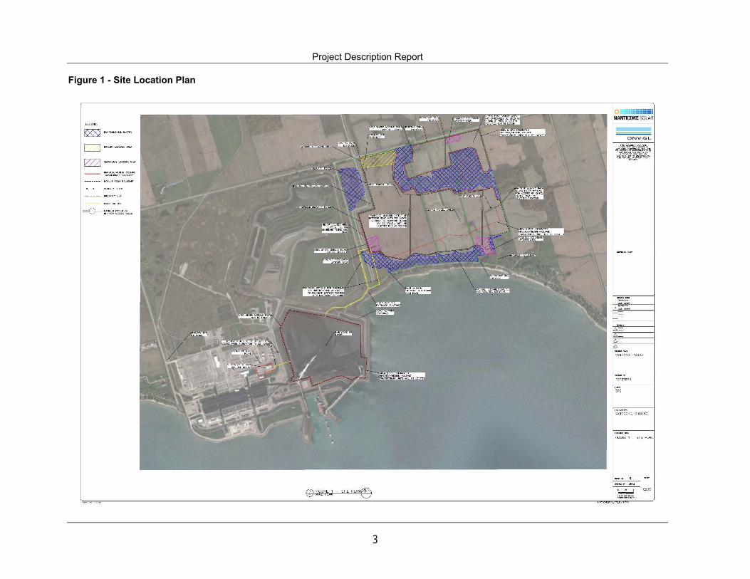
Figure 1 – Site Location Plan ......................................................................................................................... 3

Project Description Report
1
1.0 PROJECT DESCRIPTION REPORT
1.1 Nanticoke Solar
The Nanticoke solar electricity generation project (herein referred to as “The Project”) is being developed by Nanticoke Solar LP (herein referred to as “Nanticoke Solar”), which is a partnership between Ontario Power Generation (OPG), SunEdison Canadian Construction LP and Six Nations Development Corporation.
1.1.1 Project Contact
Name: Phil Shantz Title: Environmental Planning Lead; ARCADIS Address: 121 Granton Drive, Unit 12
Richmond Hill, ON L4B 3N4 Email: [email protected] Name: Gillian MacLeod Title: Senior Environmental Advisor; OPG Address: 700 University Avenue; H18D16 Toronto, ON M5G 1X6 E-mail: [email protected]
1.2 Introduction
Nanticoke Solar is proposing to design, build and operate up to a 44 megawatts alternating current (MWAC) solar electricity generation facility on and near the existing OPG Nanticoke Generating Station (G.S.) site in Haldimand County, Ontario (see Figure 1 – Site Location Plan) (“The Project”). The Project was selected through the Independent Electricity System Operator’s (IESO) Large Renewable Procurement (LRP) I Request for Proposal (RFP). The proposed Project is classified under the O.Reg. 359/09 Renewable Energy Approval (REA) process as a Class 3 Solar Facility and will generate up to 44 MWAC. The Project will convert solar energy into electricity to be fed into the Hydro One transmission grid. The Project will require approval under Ontario Regulation 359/09 – Renewable Energy Approval (REA) under Part V.0.1. of the Ontario Environmental Protection Act. Subject to receiving all approvals, the preliminary schedule anticipates that full commercial operation will be achieved by March 9, 2019. The Project has received a 20-year LRP contract from the IESO to generate electricity and deliver it to the Ontario electricity grid. As such, the project is anticipated to operate until at least 2039, at which time it may continue to generate electricity or be decommissioned.
1.3 Purpose of Report
Ontario Regulation (O. Reg.) 359/09 – Renewable Energy Approvals Under Part V.0.1 of the Act, (herein referred to as the REA Regulation), came into force on September 24, 2009 and identifies the REA requirements for renewable energy generation facilities in Ontario. As per the REA Regulation (Part II, Section 4), ground mounted solar facilities with a name plate capacity greater than 12 kilowatts (kW) are

Project Description Report
2
classified as Class 3 solar facilities and require an REA. Section 13 of the REA Regulation requires proponents of Class 3 solar facilities to prepare a Project Description Report. As prescribed by Table 1 of O. Reg. 359/09, the Project Description Report shall describe the following:
1. “Any energy sources to be used to generate electricity at the renewable energy generation facility.
2. The facilities, equipment or technology that will be used to convert the renewable energy source
or any other energy source to electricity. 3. If applicable, the class of the renewable energy generation facility. 4. The activities that will be engaged in as part of the renewable energy project. 5. The name plate capacity of the renewable energy generation facility. 6. The ownership of the land on which the Project Location is to be situated. 7. Any negative environmental effects that may result from engaging in the project. 8. An unbound, well marked, legible and reproducible map that is an appropriate size to fit on a
215 mm by 280 mm page, showing the Project Location and the land within 300 m of the Project Location.”
A draft of the Project Description Report must be made available to the public, the local municipality and identified Aboriginal communities, at least 60 days prior to the first and final public consultation meetings in accordance with O. Reg. 359/09.
1.4 Project Location and Land Ownership
The Project is located on four (4) parcels of property in Haldimand County, Ontario including the former Nanticoke G.S. site and lands nearby. The four parcels of the project land are privately owned. Rights sufficient to use the lands for construction and operation of a solar electricity generation facility have been acquired by Nanticoke Solar LP through lease agreements with private landowners. The defined project is approximately 178 hectares (ha). The following coordinates (in UTM NAD 83, Zone 17T coordinate system) define the extremities of the Project Location: Northwest: 576608.8 m E; 4740369.14 m N Northeast: 579572.74 m E; 4741098.70 m N Southeast: 579830.45 m E; 4740246.62 m N Southwest: 577038.81 m E; 4738892.65 m N
Project Description Report
3
Figure 1 - Site Location Plan
Project Description Report
4
1.4.1 Land Ownership and Parcel Description
Nanticoke Solar has leased the lands identified as the Nanticoke GS lands, the East Parcel lands, the Central Parcel lands and the West Parcel lands. The legal description of the Nanticoke GS lands parcel is Part of Lots 7, 8, 9, Concession 1, former Township of Walpole, City of Nanticoke, Regional Municipality of Haldimand-Norfolk, now in Haldimand County, Ontario. PIN: 38201-0054. The legal description of the West Parcel is Part Lot 10, Concession 1, former Township of Walpole, City of Nanticoke, Regional Municipality of Haldimand-Norfolk, now in Haldimand County, Ontario. PIN: 38201-0133. The legal description of the Central Parcel is Part of Lot 11, Concession 1, former Township of Walpole, City of Nanticoke, Regional Municipality of Haldimand-Norfolk, now in Haldimand County, Ontario. PIN: 38201-0132. The legal description of the East Parcel is Part of Lot 11 and Lot 12, Concession 1, former Township of Walpole, City of Nanticoke, Regional Municipality of Haldimand-Norfolk, now in Haldimand County, Ontario. PIN: 38201-0124. Municipal road allowances adjacent to South Cost Drive may be used for overhead or underground cables to transmit power between the East, Centre & West Parcels to the Nanticoke GS lands. The total land area of The Project is 157.9 hectares (former Coal Area – 33.5 ha, West Parcel – 61.0 ha, Centre Parcel – 33.4 ha and East Parcel – 30.0 ha).
1.5 Other Approvals Required
It is anticipated that in addition to the REA, other permits may be required, including potentially: building permits from Haldimand County, permits from the Ontario Energy Board (OEB), entrance and road use permits from Haldimand County, or permits from the Long Point Region Conservation Authority (Ontario Regulation 178/06). Also Notice of Activity filing under Ontario Endangered Species Act, 2007. Ontario Regulation 242/08
1.6 Federal Involvement
There is no expectation for requirement of a federal environmental assessment under the Canadian Environmental Assessment Act. Nor is there any expectation for the requirement of federal permits or approvals under the Fisheries Act, Species at Risk Act or any other Act.

Project Description Report
5
2.0 PROJECT INFORMATION
2.1 Project Facility and Equipment
The Project is a Class 3 Solar Facility and is proposed to have a name plate capacity of 44 MWAC. The major components of the proposed project are as follows:
Monocrystaline or polycrystalline solar photovoltaic (PV) modules; Combiner boxes and cabling; Support posts installed in the ground, and a fixed or single-axis mounting structure to hold the PV
modules; Substation (located on the Nanticoke GS lands), including: a primary transformer; switchgear; PT’s,
CT’s and metering, control and communication equipment and potentially a tower for communication if required by Hydro One;
Integrated inverter/transformer units to convert electricity from direct current to alternating current, and to step-up the voltage;
Interior access roads and turnaround areas; and, Temporary laydown/staging areas for deliveries of materials and equipment.
2.1.1 Solar Photovoltaic Modules
The solar PV technology proposed for this project is polycrystalline or monocrystaline modules, expected to be approximately 300 W to 400 W of rated power output, and each approximately 2 m long by 1 m wide. The modules will be held by a fixed structure or single-axis tracking structure which is to be supported off the ground by vertical posts.
2.1.2 Electrical System
Solar panels will be connected in series, with the collected DC power input into an inverter for conversion to AC power. The power output from the inverter will go to intermediate step-up transformers, where the voltage will be increased. The electrical cables from the intermediate step-up transformers will feed power to the main facility substation, where the main step-up transformer will match the voltage required for interconnection to the provincial power grid. Interconnection with the provincial power grid will take place within the Project Site. The point of interconnection is dependent on discussions with Hydro One and the IESO as per the System Impact Assessment (SIA) and Connection Impact Assessment (CIA) application process. The proposed point of interconnection is located within the Nanticoke GS lands. The Project will connect to the Hydro One 230kV transmission system. We will be in compliance with the Ontario Transmission Codes, IESO Market Rules and North American Electricity Reliability Corporation (NERC) requirements if applicable. The operational electrical systems will be designed in conformance with best utility safety practices.

Project Description Report
6
2.1.3 Interior Roads
Interior roads within the project site will be constructed to provide access to the inverter stations and the substation for construction activities and for maintenance activities during the operation phase. Interior road specifications will be designed in consultation with the local Fire Department. The maximum possible extent of the interior road network is shown in Figure 1 – Site Location Plan, and gravel or dirt roads may be constructed in some or all of the locations identified on the plan. Municipal road entrances (identified as primary and secondary site entrances) are identified on the Figure 1 – Site Location Plan, and use of these entrances and the municipal roads will be governed by an agreement on roads to be entered into by Nanticoke Solar with Haldimand County.
2.1.4 Communications and SCADA
It is proposed to provide Supervisory Control and Data Acquisition (SCADA) functions for remote supervisory monitoring and control. This system allows data on performance of the arrays, inverters, substations and weather conditions to be recorded and displayed at a control station, and also provides warnings if there are abnormal conditions. The operation of The Project will be remotely monitored and controlled through the SCADA system using a secure Internet connection.
2.2 Renewal Energy Generation Facility Class
Under O.Reg. 359/09, this Project is classified as a Class 3 Solar Facility.
2.3 Schedule
Nanticoke Solar received an LRP Contract on March 9, 2016. The development and permitting phase of the project started earlier, in 2015, and is expected to progress until the fourth quarter of 2017. Upon receipt of the REA, we will commence the early stages of construction, expected to be late in the fourth quarter of 2017. Construction of The Project is expected to take place from the fourth quarter of 2017, through 2018, and we expect to reach commercial operation no later than March, 2019.

Project Description Report
7
3.0 PROJECT ACTIVITIES
The Project will be composed of the following general activities:
Securing Land Rights; Planning; Permitting; Detailed Design; Construction; Operation; and, Decommissioning.
3.1 Construction Activities
3.1.1 Surveying and Geotechnical Activities
Surveys will be required to accurately locate the Constrained Buildable Area and take measurements to identify land elevations. Crews will drive all terrain vehicles to reach sites primarily using existing access roads. They will then walk the site for the surveying and mark the locations using stakes. Geotechnical sampling will also be required. This will be undertaken by a track-mounted drill rig which will drill boreholes to determine soil and/or rock characteristics. This will take approximately two weeks. Existing buried infrastructure located on public property will be located using the Ontario One Call service or equivalent, and buried infrastructure located on private property will be located by private contractors prior to construction or geotechnical sampling and updated throughout construction, as required.
3.1.2 Roads and Civil Site Preparation
No permanent paved roads will need to be constructed to bring equipment to The Project. Municipal and provincial roads will be used for transportation of materials, workers, and equipment to the construction sites, as will the existing rail line that extends onto the Nanticoke GS lands. Minor modifications and improvements may be required to some of the existing roads (for example, widening the turning radius) for equipment transportation. Any road damage caused during construction will be repaired. On-site access to the solar panels will be accessed by interior roads. Following completion of the construction phase, the interior roads will be used for maintenance and operating activities throughout the duration of The Project’s operation. The construction of the interior roads will be either temporary dirt roads, and compacted permanent interior roads. All topsoil will be kept and re-used on site. New culverts may be required to maintain drainage and to comply with best management practices of storm water management, and these will be constructed sufficient to support the construction equipment and delivery trucks. The exact culvert details (if any are required), installation details and erosion-control measures will be determined during the detailed design phase and in conjunction with the Ontario Ministry of Environment and Climate Change (MOECC).

Project Description Report
8
Construction equipment will include at a minimum: trucks, graders, light cranes, tractor trailers and bulldozers.
3.1.3 Construction Assembly and Laydown Area
Portions of the Nanticoke GS lands, and the West, Centre and East Parcel lands will be used as construction assembly and laydown areas. These areas are shown in Figure 1 – Site Location Plan. Construction of laydown areas may include the removal of topsoil, and the installation of clean compacted crushed gravel on an as-needed basis, which is planned to be re-purposed when the laydown area is no longer required. Any topsoil removed will be re-used on site. Construction equipment will include, at a minimum, trucks, graders and bulldozers.
3.1.4 Site Preparation and Inverter Station Installation
As the proposed site includes the former coal yard and agricultural lands there is little clearing and grubbing required on the land. There are a few isolated trees and bushes that would be cleared with a minor amount of vegetation removal. Some grading activities are proposed to generally level portions of the agricultural lands (this is discussed in the Conceptual Stormwater Management Plan Report, Arcadis, 2016). Prior to construction, the construction area will be fenced. The site will be surrounded by a chain-link fence approximately 2 m tall for site security. The fence post holes will be augured and the fence posts placed into concrete and allowed to set. Once the posts have been set, the metal chain link fence will then be secured. The fencing used will prevent access to large animals and humans and will prevent encroachment on natural features. Inverter/transformer units will be placed on concrete pads or metal piers. The topsoil at the inverter station will be removed and crushed gravel will be imported on an as-needed basis. The excavated topsoil will be re-used on site, as feasible. Equipment will include, at minimum, trucks, graders, cranes, cement trucks, tractor trailers and bulldozers.
3.1.5 Delivery of Equipment
Equipment will be delivered by truck and trailer as needed throughout the construction phase and stored at the temporary construction laydown area and indoor warehouse facilities within the project location. These deliveries will typically occur during normal construction hours, typically 7 am to 7 pm and may include weekends. A Conceptual Construction Traffic Management Plan will be developed in coordination with the municipality. Prior to the start of construction, a road assessment of municipal roads that may be impacted will be undertaken, and a road use agreement will be entered into with the Municipality, which will govern the use of municipal roads for equipment deliveries. Nanticoke Solar has indicated that the three roads to be utilized and that should be covered in the assessment would be Highway 55 (Nanticoke Road) to the Nanitcoke GS, Rainham Road and South Coast Drive. Railway delivery of major equipment is a possible alternative and may reduce road construction traffic. The delivery will be consistent with normal construction hours above.
Project Description Report
9
3.1.6 Installation of Racking System
Based on a geotechnical assessment and engineering report, the pile (or metal support post) design will be developed and finalized. Possible designs for the support posts include, for example: H-channel, C-channel or W-channel straight, driven or vibratory-installed piles; helical or screw piles, or cylindrical piles installed in a drilled hole (potentially using grout or concrete), or alternatively, anchored to an above-ground concrete ballast block. The module mounting structure will be affixed to the metal piles, and will be in either a fixed or single-axis tracking configuration. Further details on the racking system and supporting structures are provided in the Design and Operations Report.
3.1.7 Solar Panel Assembly and Installation
The exact quantity of modules to be used is dependent on module size, type, wattage and available space. With the exception of light crane trucks and flatbed trailers/hay wagons (storage and module transfer), the assembly work is manual and requires a number of smaller hand tools; small electrical tools may be required to join tubes that comprise the array skeleton; however, assembly via hardware connection remains the preferred form of rack assembly. Partial assembly of racking and electrical wiring may be completed by the equipment or material vendor prior to delivery to site. The installation and assembly procedure consists of mounting the structure components to the posts, fastening the rack elements together, joining tubes and mounting and fastening the PV modules to the assembled rack.
3.1.8 Electrical Collector System
The electrical collector system will consist of above-ground wiring from the panel strings to the combiner boxes, which are in turn connected to the inverter/transformer units via either above ground harnesses or direct buried cables. Harness-mounted, pole-mounted or underground cabling will then run from the inverter/transformer units to the main substation, where the voltage will be stepped up to connect to the Hydro One 230 kV transmission system. Suitable grounding will also be installed where required by applicable codes and standards.
3.1.9 Substation
The electrical substation for The Project will be located on the Nanticoke GS lands near the Hydro One Nanticoke switchyard. The substation equipment will include a 230 kV main power transformer, switchgear, station service equipment; revenue grade PT’s, CT’s and metering, a permanent control building, and control and communication equipment. The substation area will be surrounded by a chainlink fence with a locked gate.
3.1.10 Clean-up and Reclamation
Waste and debris generated during the construction activities will be collected and disposed of at an approved waste management/transfer facility. All reasonable efforts will be made to minimize waste generated and to recycle materials, including returning packaging material to suppliers for reuse/recycling. Fuelling will only occur in designated areas. During construction, industry best practices

Project Description Report
10
for spill prevention will be utilized. In the unlikely event of a minor spill, this will be cleaned up immediately and any impacted soils will be removed from site and disposed of at an approved and appropriate facility. At the conclusion of construction, vehicles and construction equipment will be removed from the site. Topsoil that was removed during construction will be replaced and re-contoured over disturbed areas, and the West, Centre and East Parcel lands will be seeded with vegetation. Stormwater control materials and equipment installed for the duration of the construction phase will be removed once inspections have determined that the threat of erosion has diminished to the original, pre-construction levels or lower. Stormwater Management activities and infrastructure will be in accordance with the Conceptual Storm Water Management Plan Report (Arcadis, 2016).
3.1.11 Project Commissioning
Commissioning of The Project will occur once the solar panels and electrical system are fully installed and Hydro One is ready to accept grid interconnection. The commissioning activities will consist of testing and inspection of the electrical, mechanical and communications systems.
3.2 Operation Activities
3.2.1 General
The Project will require technical and administrative staff to maintain and operate it. Most of The Project’s operation will be controlled automatically or remotely, through a central monitoring hub. A team of 1-2 full-time workers may be required to keep The Project operating properly and maintained regularly. Generally, a team of maintenance personnel covers a regional territory that houses multiple solar facilities. The primary workers will be electricians, grounds keepers, who carry out maintenance on the equipment, software technicians, along with a general supervisor. Solar panels operate during daytime hours, in both direct and diffuse light. Each block of modules connected to one inverter/transformer unit has a comprehensive control system that monitors the panel and electrical subsystems, as well as the local solar irradiance conditions to determine whether maintenance is required. If an event occurs which is considered to be outside the normal operating parameters of the array, such as electrical trips, panel weight overload (e.g., snow, extremely high winds), the array will immediately take itself out of service and report the condition to the SCADA system. A communication line connects each block to the monitoring hub, which closely monitors and, as required, controls the operation of the array.
3.2.2 Routine Maintenance
Routine preventative maintenance activities are scheduled at regular intervals with specific maintenance tasks scheduled for each interval. Maintenance is performed by removing the block from service and inspecting the electrical, control and mechanical systems on the array. Consumables are used, such as the various greases used to keep the mechanical components operating at peak performance. Following all maintenance work on the block, the area is cleaned. All surplus lubricants and grease-soaked rags are removed and disposed of in a prescribed manner. All maintenance activities will adhere to the same spill prevention industry best practices undertaken during the construction phase. Additional maintenance activities will include grass cutting, vegetation removal and fence repair. No pesticides or

Project Description Report
11
herbicides are planned to be used during maintenance activities. The majority of the routine maintenance can occur in evening hours.
3.2.3 Unplanned Maintenance
Modern solar panels are very reliable and the major components are designed to operate for over 25 years. However, with large numbers of modules it is inevitable that component failures will occur despite the high reliability. Most commonly, the failure of small components such as switches, fans, or sensors will take sections of The Project out of service until the faulty component is replaced. These repairs can usually be carried out by a single technician visiting The Project for several hours.
3.2.4 Electrical System
The collector lines and substation will require periodic preventative maintenance activities. Routine maintenance will include condition assessment and protective relay maintenance of the substation as well as vegetation control. Regular confirmation checks between the Hydro One and Nanticoke Solar communication system will be done on a semi-annual basis as per the IESO/Hydro One connection requirements.
3.2.5 Stray (or Tingle) Voltage
As the proposed project will be connecting to the transmission system, it will be designed and engineered to rigorous codes and standards and inspected by qualified personal to ensure that the design is properly implemented. This eliminates the risk of stray voltage. As a result, The Project will not affect area residents and animals with stray voltage. The cause stray voltage is the improper grounding that causes low voltage current to travel along a neutral wire. At a voltage difference above about 10 volts it may cause a low-level electrical shock that can produce sensation or annoyance in farm animals. Stray voltage can occur in any electrical distribution system where grounding has not been properly undertaken. Farming operations are especially susceptible to incidences of stray voltage for two reasons:
1) Many working farms have electrical systems and wiring that have not been fully updated to current electrical codes and standards.
2) Farms have higher number of potential contact points (e.g., metal), water and wet conditions, i.e. feed bowls and wet concrete floor that can serve to provide a conduit for stray voltage.
3.3 Decommissioning Activities
3.3.1 Procedures for Dismantling
If the Project is to be decommissioned and the solar array is to be removed at the end of its contract, the impacts will be similar to the construction phase, but in reverse sequence. The detailed procedures are laid out in the Decommissioning Plan Report.

Project Description Report
12
3.3.2 Land Restoration Activities
Decommissioning of The Project will not result in any negative impacts to surface or groundwater quality. Restoration of land use is not a concern for the Nanticoke GS lands, as the coal yard will never again be used to store coal; so any specific restoration activities are limited to the West, Centre and East Parcels. The Project doesn’t include any permanent changes to the original use of the West, Centre and East Parcels. Therefore, the agricultural use of the areas will be accomplished by ensuring:
Site cleanup; Any excavation and/or trenching caused by the removal of building or equipment foundations,
rack supports and underground electrical cables will be backfilled with the appropriate material and leveled to match the ground surface;
The roads, parking areas and substation yard will be removed completely, filled with suitable sub-grade material and leveled. Top soil will be placed on these areas to restore agricultural capability;
Any compacted ground will be tilled, mixed with suitable sub-grade materials and leveled.
3.3.3 Waste Disposal
Waste generated by the installation, operation and decommissioning of The Project is minimal and there are no toxic wastes generated. Any wastes generated will be disposed of according to applicable codes and standards, with the emphasis of recycling materials whenever possible.
3.3.4 Activities Schedule
Though not finalized, the tentative timing to commence the construction of The Project is during the fourth quarter of 2017, and reaching commercial operation no later than March, 2019. Specific timing of activities will be provided in the Construction Plan Report, Design and Operations Report and Decommissioning Plan Report in the complete REA submission.

Project Description Report
13
4.0 POTENTIAL ENVIRONMENTAL EFFECTS
The following sections describe the potential environmental effects of the construction, operation and decommissioning of the project. A summary of the effects as they relate to project activities is included in Table 1. An Environmental Effects Monitoring Plan to monitor the potential environmental effects is laid out in the Design and Operations Report.
4.1 Air Emissions
No air emissions requiring approval will be generated from either the construction, operation or decommissioning phases. Some vehicular emission will be generated by trucks or heavy machinery during the construction and decommissioning phases however these will be minor. There may also be some minor welding taking place on site which will result in some minor local air emissions. In order to minimize these air emissions the contractor will be required to minimize idling of equipment and, where practical, welding will take place during the fabrication stage prior to arriving on site, or on the Nanticoke GS lands.
4.2 Liquid Waste
Only minimal amounts of liquid waste will be generated during the construction, operation and decommissioning phases. This liquid waste will be comprised mainly of sewage. As no staff will be onsite on a permanent basis and no operations building will be built, this waste will be managed using portable toilet facilities which will have the waste generated disposed of offsite by a licensed contractor. It is possible that small amounts of other liquid wastes such as grease, oil and/or paint may be generated during regular maintenance activities of equipment (tracking motors and electrical equipment). Should any of these wastes be generated they will be appropriately stored in approved containers. These liquid wastes will then be transported by a licenced contractor to an approved and appropriate facility. During decommissioning liquid waste will be limited to sewage and potentially transformer oil. If the transformers are oil-type, the transformer oil will be non-hazardous (no PCBs) and will be drained and recycled offsite by a licensed third party contractor at an approved site.
4.3 Solid Waste
Solid waste will be generated during the construction, operation and decommissioning phases. During the construction period this will primarily be packing material, scrap metal and wiring and domestic type waste generated by the construction staff. The waste will be separated into recyclables (metals, wood, paper and plastics) and non-recyclables and disposed of by a licensed third party contractor and an approved and appropriate facility. During the operational phase of The Project, solid waste generation will be minimal and will be generated during maintenance activities. The waste will be similar to construction waste and will be composed of packing material, scrap metal, wiring and some domestic type waste. The waste will be separated into

Project Description Report
14
recyclables (metals, wood, paper and plastics) and non-recyclables and disposed of by a licensed third party contractor and an approved and appropriate Project. Decommissioning activities will potentially generate greater amounts of waste at the end of the operation phase. Wherever possible, project equipment including panels, inverters, transformers, racking and trackers will be sold or re-used on another site. Potential waste includes: panels, electrical equipment, scrap metal (from racking), wiring, fencing and gravel from the road construction. The waste generated during this phase will be separated into recyclable, non-recyclable and hazardous as per the regulations and industry best practices at the time of decommissioning.
4.3.1 Hazardous Waste
It is not anticipated that any significant amounts of hazardous wastes will be generated and Nanticoke Solar will attempt to procure non-hazardous alternatives whenever possible. Potential hazardous material will likely be limited to spent welding rods and used batteries. These items, if generated, will mainly be generated during the construction and decommissioning phases but some may be generated during the operational phase. No non-emergency vehicle maintenance will be permitted on the site and therefore no spent motor oil, anti-freeze or filters will be generated onsite. All hazardous wastes will be stored temporarily onsite in appropriate, clearly marked containers until the end of the construction or decommissioning phase and then disposed of by a licensed third party contractor and an approved and appropriate facility. Hazardous waste generated during maintenance activities will be removed from the site at the conclusion of that particular activity and not be stored onsite.
4.4 Stormwater
Arcadis has prepared a Conceptual Stormwater Management Plan for the proposed project. The stormwater management plan focuses on two main development areas: the coal pile located east of Nanticoke GS, and the agricultural lands located to the northeast of Nanticoke GS. The proposed stormwater management plan will utilize existing stormwater drainage patterns and features in order to minimize downstream impacts. Since solar panels do not increase the impervious area of the land surface, minimal changes to the quantity and quality of the stormwater runoff are anticipated. The impervious areas for the proposed development (i.e. gravel access roads) account for less than 1.5% of the project area. Consultation with the Long Point Region Conservation Authority has been on-going during the development of the Conceptual Stormwater Management Plan.
Coal Pile SWM Plan The coal pile area currently utilizes a stormwater management system consisting of catch basins, culverts, ditches and lagoons licensed under Environmental Compliance Approval Number 4953-99FLYS. In general, the post-development plan for this area is to utilize the current SWM infrastructure as is. The proposed development area grading and drainage is anticipated to be improved since the coal pile is removed and the area will be covered with grass to promote treatment and infiltration. No anticipated increase in stormwater runoff is expected for this proposed development area.

Project Description Report
15
West, Central and East Parcel Lands SWM Plan Existing drainage patterns, grades as well as final discharge points will be maintained, where possible. Minor alterations to site grading will be implemented to ensure the flood plain is controlled from proposed development plan area. In addition, the proposed development area will be covered with grass to promote treatment and infiltration. Minimal changes in stormwater runoff is expected for this proposed development area. Incremental increase of peak flow from the outlets of the proposed development area are maintained below 1%. Since the main discharge outlet of the proposed site area is Hickory Creek which immediately thereafter drains to Lake Erie, there are no anticipated issues posed by the marginal increase in stormwater runoff.
Erosion and Sediment Control Temporary erosion and sediment (E&S) control measures will be implemented during the construction phase of this project. In general, light duty silt fences will be implemented along the perimeter of the site as well as any watercourses, wetlands and woodlands within the proposed site development area. Additionally, hay bales will be placed around any catch basins and culverts located within the proposed site development area. Mud mats will be utilized on site entrance ways which are directed to local roadways. Once the construction phase has been completed and the vegetation has grown within the proposed development area, the temporary measures will be removed and vegetation will provide long-term E&S control. More detailed best management practices can be found in the Conceptual Stormwater Management Plan.
4.5 Water Taking Activities
There will be no permanent operations building onsite and no water taking is expected during the operations phase. Water-taking during the construction phase may be required during wet times of year to move water from one location within the project to another, in order to reduce wetness of areas where construction activities are planned. It is expected that during these short durations, no greater than 50,000L/day will be required. If a greater amount of water is required, Nanticoke Solar will seek and obtain a Permit to Take Water.
4.6 Dust
It is anticipated that some dust will be generated during construction and decommissioning activities. As vegetation will be allowed to grow under the solar panels it is not expected that dust will be generated during the operation phase. During construction and decommissioning, dust will be mainly generated by vehicle traffic over gravel roads and/or cleared areas. To minimize dust, vehicle speeds will be limited and other mitigation measures, such as wetting of roads and suspension of work during high winds, may be employed if deemed necessary.
4.7 Heritage and Archaeological Resources
Archaeology Assessment Construction of The Project will result in solar panels covering large portions of the proposed site. As such, construction has the potential to disturb archaeological resources, should they exist on the site.

Project Description Report
16
A Stage 1 and 2 archaeological assessment has been completed by This Land Archaeology Inc. along with participation from monitors from Six Nations Council and Mississaugas of New Credit. The Report is titled: Report on the Stage 1 & 2 Archaeological Assessment in Support of the Nanticoke Solar Project, Located on Part of Lots 7 – 11, Concession 3, Town of Nanticoke, Regional Municipality of Haldimand County, Geographic Township of Walpole, Ontario. That Report describes the development, historical and archaeological context of the area and the subject lands; describes the archaeological assessment methodology; and, provides an analysis of the various finds and their associated locations. The completed Stage 1 and 2 archaeological assessment resulted in the discovery of 60 archaeological resources; 39 Isolated Findspots, 15 Informal Archaeological Sites and 6 Archaeological Sites; of these resources 6 are recommended for further investigation via Stage 3 assessment (further recommendations for Stage 4 mitigation may follow upon completion of Stage 3 assessment). The report is submitted to the Ministry of Tourism, Culture and Sport as a condition of licensing in accordance with Part VI of the Ontario Heritage Act, R.S.O. 1990, c 0.18. A letter of concurrence from the Ministry of Tourism, Culture and Sport will be sought in the fall of 2016 for the above noted report. As the Stage 1 and 2 assessment did result in the identification of certain sites that will require Stage 3 and 4 assessments. Nanticoke Solar expects to complete Stage 4 assessments on all the sites and therefore free up all the lands for construction. If however, decisions are made to not undertake specific Stage 4 assessments the finds will be appropriately protected and buffered from development. The Stage 3 and 4 work would be undertaken in 2017 with the resultant studies submitted to MTCS and concurrence letters obtained prior to the start of construction. Archaeological sites recommended for further archaeological fieldwork or protection remain subject to Section 48 (1) of the Ontario Heritage Act and may not be altered, or have artifacts removed from them, except by a person holding an archaeological licence. If during construction any previously undocumented archaeological resources are discovered, work will be immediately suspended in the vicinity of the find and a licensed archaeologist will be contracted to assess the find and make further recommendations. . The Cemeteries Act, R.S.O. 1990 c. C. 4 and the Funeral, Burial and Cremation Services Act, 2002, S.O. 2002, c.33 (when proclaimed in force) require any person discovering human remains must notify the police or coroner and the Registrar of Cemeteries at the Ministry of Consumer Services. Cultural Heritage Assessment A cultural heritage assessment titled: Cultural Heritage Assessment Report: Proposed Nanticoke OPG Solar Project by Chris Uchiyama Heritage has been undertaken and submitted to MTCS. This Report is available for public review and is available on the Nanticoke Solar website. Based on the current design of the project, no negative project related impacts on potential heritage attributes have been identified.

Project Description Report
17
4.8 Natural Heritage and Water Features
4.8.1 Natural Heritage
Beacon Environmental Limited (Beacon) prepared a Natural Heritage Assessment and Environmental Impact Assessment Study. The Natural Heritage Assessment and Environmental Impact Study is required to fulfil the requirement under Ontario Regulation 359/09 - Renewable Energy Approvals under Part V.0.1 of the Act of the Environmental Protection Act (O. Reg. 359/09). The Natural Heritage Assessment (NHA) report is provided to the Ministry of Natural Resources and Forestry for review and confirmation as part of the Renewable Energy Approval (REA) application to the Ministry of Environment and Climate Change (MOECC). A NHA is required for proposed renewable energy projects to determine whether the following natural heritage features are within 120 m and 50 m of the proposed project location: Significant Woodlands; Significant Wetlands; Significant Valleylands; Significant Wildlife Habitat; Provincial Parks; Conservation Reserves; or Area of Natural and Scientific Interest (Earth or Life Science). An Environmental Impact Study (EIS) report was prepared to identify any potential negative environmental effects during construction, operation and decommissioning, and how they will be addressed during mitigation and monitoring. The Natural Heritage Assessment and Environmental Impact Study includes a Records Review, Site Investigation, Evaluation of Significance, and Environmental Impact Study (EIS) where any natural features within the Project Location, and the lands within 50 m of the project location were identified. The following natural heritage features were identified as being in or within 50 m of the Project Location during the background review, consultation with agencies, and field investigation, and were therefore carried forward to the EIS:
Wetlands; Woodlands; Planted Tallgrass Prairie; Planted Species of Special Concern (Nodding Wild Onion, Pale-Purple Coneflower, Prairie Dock
and Tall Coreopsis), which are all associated with the Planted Prairie Feature; and Generalized Candidate Significant Wildlife including:
o Bat Maternity Colonies; o Species of Special Concern – Woodland Plants (Harlberd-leaved Smartweed, Hirsute Sedge
and Weak Stellate Sedge); o Bird Species of Special Concern (Eastern Wood-Pewee, Peregrine Falcon and Red-headed
Woodpecker); o Reptiles and Amphibians of Special Concern (Eastern Ribbonsnake, Jefferson / Blue-Spotted
Salamander Complex and Snapping Turtle); and o Woodland Vole.
Four of the six wetlands identified through the Site Investigation were assumed to be significant and evaluated using the evaluation of significance criteria. There is no development proposed within any wetlands that are assumed to be significant in or within 50 m of the Project Location. No direct impacts to wetlands that have assumed to be significant that are located in or within 50 m of the Project Location are anticipated as there will be not direct loss of wetland habitat or function, and a minimum 20 m buffer is being maintained from the edge of each woodland to the nearest Project component.

Project Description Report
18
Potential negative effects to wetlands associated with the construction, operation, and decommissioning phases of the Project are outlined in detail within Table 13 of the Natural Heritage Assessment and Environmental Impact Study along with mitigation measures. Three of the woodlands in or within 50 m of the Project Location meet the criteria for significance based on the evaluation of significance criteria outlined in the NHA Guide for Renewable Energy Projects (Figure 6 of the Natural Heritage Assessment and Environmental Impact Study). There is no development proposed within any significant woodland. The specific distance from each significant woodland to the Project Location is provided in Table 12 of the Natural Heritage Assessment and Environmental Impact Study; a minimum 10 m buffer has been maintained from the boundary of each woodland to the Project Location. No direct impacts to woodlands are anticipated as no woodland is being removed, and a minimum 10 m buffer is being maintained from the edge of each woodland to the nearest Project component. Indirect negative effects to woodlands resulting from construction and decommissioning activities including dust generation, sediment and erosion, waste management are expected to be temporary, and will be mitigated through standard construction management practices. Other indirect impacts may occur though accidental spills or accidental damage to tree roots or limbs. All indirect negative effects will be controlled through the use of standard mitigation measures, as outlined Natural Heritage Assessment and Environmental Impact Study.
The proposed mitigation measures for wetlands and woodlands would include the following:
Design and implement erosion and sediment control plan – including silt fences when work is within 30 m of a wetland or woodland;
Temporarily suspend work if excessive runoff or sediment is observed; Stockpile materials at a distance greater than 30 m from wetlands and woodlands; Use pervious materials on roads; Limit traffic on disturbed soil; Maintain existing grading, where feasible; Construct roads at or near existing grade, where feasible; Maintain fence around perimeter of Project – discourage workers from entering wetland and
woodland areas; Maintain minimum of 20 m buffer around wetlands and 10 m around woodlands; Stabilize and/or re-vegetate all areas of disturbed soils that drain into wetlands and woodlands; Identify a designated area for equipment maintenance and fueling; Storage of fuel should only occur in permitted areas; Maintain an emergency spill kit on-site in case of emergency; Develop a spill response plan; Use native seed mixes; Use native topsoil; Clearly delineate work area prior to construction; Discourage workers from entering woodland and wetland areas; If lighting of the area is proposed as part of the development plan ensure that it is installed in such
a way that light is not directed towards natural areas either through the strategic placement of lights or the use of light shields; and
Clearly post speed limits.

Project Description Report
19
A Planted Tallgrass Prairie is located in the centre of the Project Location. The planted prairie and the planted Species of Conservation Concern will be removed to facilitate the installation of the solar panels, perimeter fence and access road. The removal of the planted prairie feature and these plants will be permanent. A compensation habitat has been identified. The new habitat will include 27.9 ha of grassed habitat and more details are provided in the Natural Heritage Assessment Report. Five Generalized Candidate Significant Wildlife habitat types were identified within the 50 m setback from the Project Location; however, it is not expected that construction or decommissioning activities will have any negative effect on these features. As outlined in the NHA Guide for Renewable Energy Projects (OMNR 2012), potential impacts to these habitats are typically associated with the temporary disturbance from construction and decommissioning activities and are grouped together as generalized impacts and mitigation measures. As described above, removal of vegetation within significant natural features will be limited to the planted tallgrass prairie. Additional vegetation removal will occur within the agricultural fields, and within hedgerows. When vegetation removal is required, the following mitigation measures will be implemented:
When appropriate, the limits of the vegetation to be cleared will be identified prior to clearing so that the minimum required amount of vegetation is removed;
When clearing is to occur adjacent to a natural feature, the limit of the clearing area will be staked so that sensitive natural features are not disturbed;
Clearing limits will be monitored to ensure that no encroachment on natural features has occurred, and the minimum amount of vegetation is removed;
If encroachment on a natural feature occurs, restoration of the feature may take place under the direction of a qualified biologist.
The federal Migratory Bird Convention Act (1994) protects the nests, eggs and young of most bird species from harm or destruction. Environment Canada considers the ‘general nesting period’ of breeding birds in southern Ontario to be between late March and the end of August. This includes times at the beginning and end of the season when only a few species might be nesting. In light of this we recommend that during the peak period of bird nesting, between April 01 and August 15, no vegetation clearing or disturbance to nesting bird habitat occur. Vegetation includes grasses. In the ‘shoulder’ seasons of, we suggest that vegetation clearing could occur, but only after an ecologist with appropriate avian knowledge has surveyed the area to confirm lack of nesting. If evidence of nesting is observed, then vegetation clearing (in an area around the nest) has to wait until nesting has concluded. Generally speaking, the smaller and simpler the habitat is, the easier it is to confirm that no nesting is occurring. Likelihood of nesting birds being present in the ‘shoulder’ seasons also depends on the habitat type. Between September 1 and March 31, vegetation clearing can occur without nest surveys, but the law for nest protection still holds (i.e. if an active nest is known it should be protected).
4.8.2 Water Features
Beacon and ARCADIS prepared a Water Assessment and Waterbody Report for Nanticoke Solar Project. A Water Assessment is a required component of a REA application. The Water Assessment includes a records review and a site investigation to determine the presence and the boundaries of waterbodies as defined by O.Reg. 359/09 and are within 120 metres (m) of the Project Location or within 300 m of the average annual high water mark of a Lake Trout lake that is at or above development capacity. If

Project Description Report
20
waterbodies are identified within 120 m of the Project Location, a Waterbody Report (including an EIS) is required. The Water Assessment and Waterbody Report identified one Lake (Lake Erie) and two of eight watercourses met the definition of waterbodies as specified in O. Reg. 359/09. The remainder of the water features identified through the Records Review either could not be located during ground-truthing (as they were not present) or were features that did not meet the definition of a waterbody under O. Reg. 359/09. Within the Project Location and 120 m setback; one watercourse, WC2 or an unnamed tributary of Hickory Creek was determined to be a permanent stream; and WC7, also an unnamed tributary of Hickory Creek was determined to be an intermittent stream (see Figure 4 in the Water Assessment and Waterbody Report for Nanticoke Solar Project). The site investigation confirmed that portions of the Project are located within 120 m of the Lake Erie shoreline and, in the case of the solar panel field proposed for the former coal pile, encroached on the 30 m buffer adjacent to the hardened shoreline. All three features were advanced to an EIS as per sections 37 and 38 of O. Reg 359/09. Potential negative effects to water features associated with the construction, operation, and decommissioning phases of the Project are outlined in detail within Table 9 of the Water Assessment and Waterbody Report for Nanticoke Solar Project along with mitigation measures. The proposed mitigation measures would include:
Prohibit access to waterbodies and riparian area; Maintain a minimum 30 m vegetated buffer from waterbodies; Design and implement erosion and sediment controls; Stabilize and/or re-vegetate all areas of disturbed soils that drain into watercourse; Design drainage system to avoid diversion of, or otherwise minimize changes in drainage; Develop a spill response plan; Incorporate a designated area for equipment maintenance and fueling; Store fuel in permitted areas; Maintain an emergency spill kit on-site in case of emergency; All equipment should be maintained in good working order and be free of material that could
contribute deleterious substances to waterbodies; Fuelling areas and storage should be kept at least 30 m from all watercourses and waterbodies; Confirm erosion hazard setback limit for any physical structures; Stabilize any areas impacted within erosion hazard limits; Control post-development flow rates from the site outlets to maintain the pre-development levels in
consultation with the Long Point Region Conservation Authority; If removal of vegetation within the vicinity of the watercourses is necessary it should be undertaken
when the channels are dry or during low flow conditions thereby reducing the potential for increased erosion and sediment transport into the watercourses;
A comprehensive erosion and sediment control plan will be developed and implemented during the construction and decommissioning phases of the project to reduce or eliminate the transport of sediments, nutrients, contaminants, and increased turbidity within these features (see Conceptual Stormwater Management Plan Report, Arcadis 2016). Siltation and erosion controls should be installed before any work on the Project Location begins, and removed after the threat of siltation and erosion effects has ceased. The siltation and erosion measures should be checked regularly

Project Description Report
21
during the construction and decommissioning phases to ensure it remains in good condition. Any deficiencies in the measures should be repaired;
Grading activities should aim to minimize changes in natural drainage in order to reduce the potential for changes to hydrological patterns.
The southern portion of the Project Location encroaches within the 30 m setback from the Lake Erie shoreline. This location described above is within the decommissioned Nanticoke GS coal storage facility that is protected from Lake Erie by a berm/perimeter road and armor stone/riprap revetment. Stormwater runoff from the former coal storage area is managed by an onsite treatment system to prevent any contaminated runoff from reaching Lake Erie. The storage facility has been rehabilitated and the stormwater management system will remain in place as outlined in the Conceptual Stormwater Management Report. The specific location where the encroachment occurs is in a portion of the coal storage area that also encroaches within this limit (the berm/perimeter road is modified at this location to allow for the encroachment, while still protecting the area from Lake Erie). The potential project effects and standard mitigation measures outlined above will also be put in place for this area. In addition, and as indicated above any stormwater in this location is managed by the onsite treatment system already in existence.
4.9 Air, Odour, Dust
The Project is a Class 3 solar facility and will not emit any air or odour emissions beyond those described in section 4.1. Some dust is expected to be created during construction and decommissioning. Further discussion of the potential effects and mitigation measures is included in section 4.7.
4.10 Noise
A temporary increase in ambient environmental noise during construction will occur due to increased traffic and the operation of construction equipment. Nanticoke Solar will adhere to the requirements of: all Haldimand by-laws. The Project proposes installing transformers, inverters and a substation. Each of these will emit some sound. Noise modeling in accordance with MOE standards is being submitted as part of this REA application and The Project will be in compliance with all applicable requirements, codes, and regulations. Arcadis has completed a draft Acoustic Assessment Report which provides more detail on the modeling and analysis.
4.11 Local Interest, Land Use and Resources
The construction, operation and decommissioning of The Project is not expected to affect land use and resources. A table of Official Plan and zoning by-law designations for the various parcels of lands is shown below in Table 1 below.

Project Description Report
22
Table 2 – Table of Official Plan and Zoning Designations
Site Official Plan Zoning Nanticoke site (former coal yard) Major Industrial MH – Heavy Industrial West Parcel Major Industrial
Riverine Hazard Lands Lakeshore Hazard Lands
MH – Heavy Industrial HL – Hazard Lands
Central Parcel Mineral Aggregate Resource Areas
Riverine Hazard Lands Lakeshore Hazard Lands
A – Agricultural HL – Hazard Lands
Eastern Parcel Mineral Aggregate Resource Areas
Riverine Hazard Lands Lakeshore Hazard Lands
A – Agricultural HL – Hazard Lands
A Conceptual Construction Traffic Management Plan will be developed. Imperial Oil-owned pipelines run adjacent to The Project, but are outside of the subject lands.
4.12 Provincial and Local Infrastructure
The construction, operation and decommissioning of The Project is not expected to significantly affect provincial or local infrastructure. Some increase in local traffic along Rainham Rd. (CR 3) and Nanticoke Road (CR 55) will occur during construction and decommissioning activities. Consultations are underway with the local and regional municipalities to ensure that any disruptions and road impacts are minimal.
MTO has indicated that they have no concerns associated with The Project.
4.13 Public Health and Safety
The construction, operation and decommissioning of The Project is not expected to significantly affect public health and safety. During construction and decommissioning the site will be surrounded by temporary fencing to prevent access to the public. The electrical equipment will be designed and installed in accordance with all applicable codes & standards and will be equipped with proper safety signage. The operational site and transformer substation will be surrounded by a fence to prevent public and large animal access.
4.14 Areas Protected under Provincial Plans and Policies
The project will not impact any lands under Provincial Plans and Policies. The site is not located in an area covered by: the Greenbelt Act or plan; The Oak Ridges Moraine Conservation Plan Area; The Niagara Escarpment Plan Area; or The Lake Simcoe Watershed Plan.
4.15 Summary of Potential Effects and Potential Mitigation Measures
A preliminary summary of potential effects and potential mitigation measures are presented in Table 2 below.

Project Description Report
23
Table 3 – Summary of Project Activities, Potential Environmental Effects, Causes, Mitigation Strategy, Residual Effect, Monitoring and Contingency Measures
Project Activity
Potential Effects and Possible Causes
Mitigation Strategy
Residual Effects, Monitoring Plan and Contingency Measures
Construction Activities
Construction Activities Disturbances to wildlife & natural features due to general construction activities Causes: General Construction Activities
• Adherence to woodland and wetland setbacks. • Use of perimeter fencing. • No encroachment on woodlands or wetlands. • Adhere to sediment and erosion control plan. • Minimize time required to complete activities. • If vegetation clearing required, it will occur outside
the breeding bird period. • Develop a spill response plan and incorporate a
designated area for equipment maintenance and fueling.
• Clearly delineate work area prior to construction. • Discourage workers from entering woodlands and
wetlands. • Ensure lighting is not directed towards natural areas
either through the strategic placement of lights or the use of light shields.
• Enforce speed limits. • Wildlife will not be harassed or fed. • Nuisance wildlife will be reported to the
environmental inspector. If the situation poses a danger to the crew or animals, the Ministry of Natural Resources will be contacted.
• Vehicle traffic will be limited to 30 km/h or less on access driveways to reduce the potential for collisions with wildlife.
• No residual effects anticipated • Construction inspection and surveying to maintain
setbacks and integrity of exclusion/siltation fencing
Contingency Measures • Suspend construction near features/nests during
general nesting period for breeding bird
Alternations to Site Topography due to Grading Operations Causes: Site Grading
• Minor alterations to site grading will be implemented to ensure the flood plain is controlled from proposed development plan area.
• Excavated soil will be re-used on-site. • Proper use of sedimentation and erosion controls.
• No residual effects anticipated • Inspection of top soil separating • Construction inspection and surveying
Contingency Measures • Review of site grading plan.

Project Description Report
24
Project Activity
Potential Effects and Possible Causes
Mitigation Strategy
Residual Effects, Monitoring Plan and Contingency Measures
Construction Activities (Cont’d)
Impacts to surface water features from construction Causes: Most Construction Activities
• Prohibit access to waterbodies and riparian area. • Maintain a minimum 30 m vegetated buffer. • Design and implement erosion and sediment
controls. • Stabilize and/or re-vegetate all areas of disturbed
soils that drain into watercourse. • Design drainage system to avoid diversion of, or
otherwise minimize changes in drainage. Minimal grading.
• Develop a spill response plan and incorporate a designated area for equipment maintenance and fueling.
• Storage of fuel should only occur in permitted areas and maintain an emergency spill kit on-site in case of emergency.
• All equipment should be maintained in good working order and be free of deleterious substances. Fuelling areas and storage should be kept at least 30 m from all watercourses and waterbodies.
• Confirm erosion hazard setback limit for any physical structures.
• Control post-development flow rates from the site outlets to maintain the pre-development levels.
• If removal of vegetation within the vicinity of the watercourses is necessary it should be undertaken when the channels are dry or during low flow.
• A comprehensive erosion and sediment control planwill be developed and implemented.
• No residual effects anticipated • Routine inspection and maintenance of erosion control
devices • Inspection of final restored surfaces to ensure
vegetation re-growth
Contingency Measures • Repair, replace or installation of additional erosion
control measures
A short-term increase in truck traffic during construction period. Potential Causes: More traffic associated with project
• Delivery of equipment will be coordinated with local traffic patterns.
• Traffic control plan will be developed.
• Minor traffic delays may be needed

Project Description Report
25
Project Activity
Potential Effects and Possible Causes
Mitigation Strategy
Residual Effects, Monitoring Plan and Contingency Measures
Construction Activities (Cont’d)
Impact on Archaeological resources Potential Causes: Ground Disturbing Activities
• A Stage 3 and 4 archaeological assessment will be undertaken as per the recommendations in the Stage 1 and 2 Report.
• If a Stage 4 assessment is not completed on certain finds the areas will be protected and appropriately buffered.
• If during construction any previously undocumented archaeological resources are discovered, work will be immediately suspended in the vicinity of the find and a licensed archaeologist will be contracted to assess the find and make further recommendations.
• Any person discovering human remains must notify the police or coroner and the Registrar of Cemeteries at the Ministry of Consumer Services.
• No residual effects anticipated
Impact to local groundwater quality Potential Causes: Accidental releases of fuels, lubricants, deleterious materials, etc.
• Any leak or spills from trucks or machinery would becontained and site would be properly cleaned up and disposed of at registered disposal facilities.
• Refuelling of all vehicles will be done away from watercourses during construction and no re-fuelling on-site during the operation phase.
• Develop a spill response plan and incorporate a designated area for equipment maintenance and fueling.
• Storage of fuel should only occur in permitted areas and maintain an emergency spill kit on-site in case of emergency.
• All equipment should be maintained in good working order and be free of deleterious substances. Fuelling areas and storage should be kept at least 30 m from all watercourses and waterbodies.
• No residual effects anticipated
Contingency Measures • Notification of Spills Action Centre, if required • Assess and remediate impacted soils
May experience annoyance with dust and/or noise Potential Causes: General construction activities
• Dust suppression measures will be employed, as necessary.
• On-site supervisor to address any noise complaints.
• Minor short-term annoyances

Project Description Report
26
Project Activity
Potential Effects and Possible Causes
Mitigation Strategy
Residual Effects, Monitoring Plan and Contingency Measures
Operational Activities
Solar Project Operation Reduction in aesthetic quality of landscape
Potential Cause: Construction
• Complaints tracking. • Adherence to noise setbacks will site inverters
away from residents.
• No residual effects anticipated
Disturbance to wildlife and birds
• Adherence to setbacks. • Discourage workers from entering woodlands and
wetlands. • Implement Spill Response Plan. • Ensure lighting is not directed towards natural
areas either through the strategic placement of lights or the use of light shields.
• Enforce speed limits.
• No residual effects anticipated
Noise impacts on receptors (residents located on non- lease properties)
• Adherence to noise setbacks • Noise modelling to predict sound levels • Repair equipment in a timely manner • Complaints tracking
• No residual effects anticipated
Spill of transformer oil • Secondary containment systems • Proper disposal of waste materials
• No residual effects anticipated
Contingency Measures • Notification of Spills Action Centre, if required • Assess and remediate impacted soils

Project Description Report
27
Project Activity
Potential Effects and Possible Causes
Mitigation Strategy
Residual Effects, Monitoring Plan and Contingency Measures
Decommissioning Activities
Removal of Equipment Surficial disturbance • Minimize changes to land contours and natural drainage.
• Install erosion control measures. • Install light duty sedimentation fencing between
proposed development and all water features.
• No residual effects anticipated • Frequent inspection of erosion control devices • Inspection of final restored surfaces • On-going consultation with landowners
Contingency Measures • Repair, replace or installation of additional erosion
control measures
Disturbances to wildlife & birds due to decommissioning activities
• Adherence to woodland and wetland setbacks. • Installation of exclusion fencing between
decommissioning zone and significant wildlife habitat.
• Minimize time required to complete activities. • Enforce speed limits. • Install erosion control measures.
• No residual effects anticipated • Routine inspection and surveying to maintain setbacks
and integrity of exclusion fencing
Contingency Measures • Alter location of project components • Suspend work during breeding periods
Sensory disturbance (sound and visual presence)
• Complaints tracking. • Impacts from equipment usage & personnel
present will be short term.
• Minor short-term annoyance
Dust • Watering of exposed soils. • Maximum speeds.
• Minor short-term annoyance • Recording and communication of complaints to local
authorities
Surficial disturbance • Install erosion control measures. • No residual effects anticipated • Frequent inspection of erosion control devices • Inspection of final restored surfaces • On-going consultation with landowners
Contingency Measures • Repair, replace or installation of additional erosion
control measures

Project Description Report
28
Project Activity
Potential Effects
Mitigation Strategy
Residual Effects, Monitoring Plan and Contingency Measures
Decommissioning Activities (Cont’d)
Removal of Transformer Spill of transformer oil • An oil containment system will be maintained during decommissioning to prevent soil contamination in the event of a leak.
• Proper disposal of waste materials.
• No residual effects anticipated Contingency Measures • Notification of Spills Action Centre, if required • Assess and remediate impacted soils
Accidents and Malfunctions
Accidents & Malfunctions
Land contamination from lubricant/transformer fluid leak or spill
• Any leak or spills from trucks or machinery would be contained and site would be properly cleaned up and disposed of at registered disposal facilities.
• Transformers used in the project are silicone based and do not contain hydrocarbons.
• Refuelling of all vehicles and equipment will be done away from watercourses during construction.
• No re-fuelling on-site during operation phase.
• No residual effects anticipated
Contingency Measures • Notification of Spills Action Centre, if required • Assess and remediate impacted soils
Public safety • Proper signage warning of electrical danger. • Siting on private property which restricts public
access to the site. • Fencing of the project area for security based on
standard utility practices.
• No residual effects anticipated