draft maltese standard sm 3700:2017 - … · draft maltese standard sm 3700:2017 green roofs –...
TRANSCRIPT

DRAFT MALTESE STANDARD SM 3700:2017
Green Roofs –
Criteria for the planning, construction, control and maintenance of Green
Roofs
ICS: 27.160
The Malta Competition and Consumer Affairs
Authority has approved and endorsed this
standard which now has the status of a
National Standard as from the date of its
publication in the official Government Gazette.
Malta Competition and Consumer Affairs Authority
Standards and Metrology Institute
Standardization Directorate
Mizzi House, National Road
Blata l-Bajda, HMR 9010
Malta
No part of this publication may be photocopied
or otherwise reproduced without the prior
permission in writing of the Malta Consumer
and Competition Affairs Authority. © MCCAA
2017.

DRAFT MALTESE STANDARD SM 3700:2017
2
Contents Page
1. Scope of the standard ............................................................................................................................................ 5
2. Normative references ............................................................................................................................................ 5
3. Terms and Definitions ............................................................................................................................................ 6
4. Introduction ........................................................................................................................................................... 7
4.1. Why Green Roofs? ....................................................................................................................................... 7
4.2. Green Roofs Benefits ................................................................................................................................... 8
5. Types of Green Roofs ............................................................................................................................................. 8
5.1. General Information .................................................................................................................................... 8
5.2. Extensive Green Roofs ................................................................................................................................. 8
5.3. Simple intensive Green Roofs ...................................................................................................................... 9
5.4. Intensive Green Roofs ................................................................................................................................. 9
6. Planning of Green Roofs ...................................................................................................................................... 10
6.1. Agents and requirements .......................................................................................................................... 10
6.2 Structural Requirements ........................................................................................................................... 10
6.3 Planning .................................................................................................................................................... 10
6.4 Site Analysis ............................................................................................................................................... 11
6.5 Certification of the structure ..................................................................................................................... 12
6.6 Access and use of Green Roofs .................................................................................................................. 12
6.7 Roof falls.................................................................................................................................................... 12
6.8 Roof designs and suitability for Green Roofs ............................................................................................. 13
6.9 Water tightness and damp-proofing.......................................................................................................... 13
6.10 Design loads .............................................................................................................................................. 14
6.11 Health and Safety Measures ...................................................................................................................... 14
6.12 Draining ..................................................................................................................................................... 15
6.13 Irrigation.................................................................................................................................................... 16
6.14 Compatibility of materials ......................................................................................................................... 16
6.15 Environmental compatibility...................................................................................................................... 16
6.16 Phytotoxicity and harm to fauna ............................................................................................................... 16
7 Materials and Components .................................................................................................................................. 17
7.1 Green Roof layers ...................................................................................................................................... 17
7.2 Depth of Green Roofs ................................................................................................................................ 18
7.3 Vegetation ................................................................................................................................................. 18
7.4 Vegetation support layer (Also referred to as substrate / growing media) ................................................ 21
7.5 Filter layer (also referred to as Geotextile) ................................................................................................ 30

DRAFT MALTESE STANDARD SM 3700:2017
3
7.6 Drainage course ........................................................................................................................................ 33
7.7 Protection layer ......................................................................................................................................... 39
7.8 Root-resistant barrier ................................................................................................................................ 41
7.9 Separation layer ........................................................................................................................................ 43
7.10 Anti-bonding layer ..................................................................................................................................... 43
7.11 Water Proofing Layer ................................................................................................................................ 43
8. Other considerations............................................................................................................................................ 45
8.1 Water retention ........................................................................................................................................ 45
8.2 Protection against sintering ....................................................................................................................... 48
8.3 Drainage systems ...................................................................................................................................... 48
8.4 Joints ......................................................................................................................................................... 49
8.5 Protection against emissions ..................................................................................................................... 51
8.6 Wind loads ................................................................................................................................................ 51
8.7 Fire characteristics .................................................................................................................................... 52
8.8 Edging ....................................................................................................................................................... 52
8.9 Paved surfaces........................................................................................................................................... 53
8.10 Furnishings ................................................................................................................................................ 54
9. Controls (Final Inspection) ................................................................................................................................... 55
10. Maintenance ..................................................................................................................................................... 56
10.1 General ...................................................................................................................................................... 57
10.2 Maintenance of the soft landscaped areas; ............................................................................................... 57
10.3 Initial maintenance to achieve the projected greening;............................................................................. 57
10.4 Long-term maintenance ............................................................................................................................ 58
10.5 Unscheduled maintenance ........................................................................................................................ 58
10.6 Maintenance to the rain water drainage system ....................................................................................... 58
10.7 Maintenance of services ............................................................................................................................ 58
10.8 Periodic inspections on the irrigation system ............................................................................................ 58
10.9 Repairs ...................................................................................................................................................... 59
10.10 The irrigation control system ..................................................................................................................... 59
APPENDIX A .................................................................................................................................................................. 60
APPENDIX B .................................................................................................................................................................. 61
APPENDIX C .................................................................................................................................................................. 63

DRAFT MALTESE STANDARD SM 3700:2017
4
Foreword
This Standard provides professionals with information to ensure that Green Roofs systems are planned, constructed and maintained in accordance to best practices and within the Maltese legal framework. This Standard has been developed following the need to identify best practices to plan, construct and maintained Green Roofs on new and existing roofs taking into account the Maltese Islands environment, not necessarily clearly defined in the local regulations, existing standards and codes. The standard is applicable to simple, intensive and extensive Green Roofs, roof terraces, underground car parks and other building and structures. This Standard does not cover all possible scenarios, on-going developing technologies and all features related to Green Roofs. Further standards addressing other matters related to the Green Roofs systems in the Maltese Islands are expected to follow when the need arises. This Maltese Standard was drawn up by SMI/TC3700. The members of this technical committee represented the following entities: Building Industry Consultative Council (BICC) Chamber of Engineers (COE) Doric Studio Environment and Resources Authority F. Zammit Garden Centre Kamra Tal-Periti Malta Competition and Consumer Affairs Authority Malta Developers Association Malta College of Arts, Science and Technology (MCAST) Margit Waas (Personal Basis) Minoprio Analisi e Certificazioni S.r.l. (IT) (MAC) Occupational Health and Safety Authority PRO Naturali Ltd Restoration Directorate University of Malta

DRAFT MALTESE STANDARD SM 3700:2017
5
1. Scope of the standard The purpose of this standard is to set out the basic principles and requirements which apply in general terms to the planning, construction and maintenance of Green Roofs. This standard is intended for use by professionals and trades people working in all relevant sectors and trades.
2. Normative references This Standard incorporates by dated or undated reference, provisions from other publications. These normative references are cited at the appropriate places in the text and the publications are listed hereafter. For dated references, subsequent amendments to or revisions of any of these publications apply to this Standard only when incorporated in it by amendment or revision. For undated references the latest edition of the publication referred to applies (including amendments).
Regulation (EU) No 1143/2014 of the European Parliament and the Council of 22 October 2014 on the prevention and management of the introduction and spread of invasive alien species
Commission Implementing Regulation (EU) 2016/1141 of 13 July 2016 adopting a list of invasive alien species of Union concern pursuant to Regulation (EU) No 1143/2014 of the European Parliament and of the Council
S.L.549.64 Trees and Woodlands Protection Regulation
S.L.549.44 Flora, Fauna and Natural Habitats Protection Regulations
Guidelines on Trees, Shrubs and Plants for Planting and Landscaping in the Maltese Islands Environmental Management Unit, January 2002, ERA
Guidelines for the planning, construction and maintenance of Green Roofs, FLL, 2008 edition
Act XXVII/2000 Occupational Health and Safety
Legal Notice 44 of 2002, as amended by Legal Notice 437 of 2012. Work Place (Minimum Health and Safety Requirements) Regulations [S.L.424.15].
Legal Notice 36 of 2012. Occupational Health and Safety (Payment of Penalties) Regulations [S.L.424.33].
Legal Notice 281 of 2004. Work Place (Minimum Health and Safety Requirements for Work at Construction Sites) Regulations [S.L.424.29].
Construction Products Regulation (EU) No 305/2011 of the European Parliament and of the Council of 9 March 2011 laying down harmonised conditions for the marketing of construction products and repealing Council Directive 89/106/EE
MSA EN 12056-3:2000 Gravity drainage systems inside buildings. Roof drainage, layout and calculation.
MSA EN 15428:2007 Soil improvers and growing media. Determination of particle size distribution
MSA EN 13041:2011 Soil improvers and growing media. Determination of physical properties. Dry bulk density, air volume, water volume, shrinkage value and total pore space.
MSA EN 13037:2011. Soil improvers and growing media. Determination of pH
MSA EN 13038:2011. Soil improvers and growing media. Determination of electrical conductivity.
MSA EN 13039:2011 Soil improvers and growing media. Determination of organic matter content and ash.
MSA EN ISO 13438:2004. Geotextiles and geotextile-related products. Screening test method for determining the resistance to oxidation.
MSA EN 13650:2001 Soil improvers and growing media. Extraction of aqua regia soluble elements.
MSA EN 16086-2:2011 Soil improvers and growing media. Determination of plant response. Petri dish test using cress
MSA EN 12225:2000 Geotextiles and geotextile-related products. Method for determining the microbiological resistance by a soil burial test.
MSA EN 1107-1:2000 Flexible sheets for waterproofing. Determination of dimensional stability. Bitumen sheets for roof waterproofing.
MSA EN 1107-2:2001. Flexible sheets for waterproofing. Determination of dimensional stability. Plastic and rubber sheets for roof waterproofing.
MSA EN ISO 12236:2006 Geosynthetics. Static puncture test (CBR test).

DRAFT MALTESE STANDARD SM 3700:2017
6
MSA EN ISO 12958:2010 Geotextiles and geotextile-related products. Determination of water flow capacity in their plane.
MSA EN ISO 9863-2:1996 Geotextiles and geotextile-related products. Determination of thickness at specified pressures. Procedure for determination of thickness of single layers of multilayer products
MSA EN 13948:2007 Flexible sheets for waterproofing. Bitumen, plastic and rubber sheets for roof waterproofing. Determination of resistance to root penetration.
MSA EN 1296:2001 Flexible sheets for waterproofing. Bitumen, plastic and rubber sheets for roofing. Method of artificial ageing by long term exposure to elevated temperature.
MSA EN ISO 846:1997. Plastics. Evaluation of the action of microorganisms.
SM EN ISO 10309:2016 Metallic coatings. Porosity tests. Ferroxyl test.
SM EN ISO 9863-1:2016 Geosynthetics. Determination of thickness at specified pressures. Single layers
SM EN 12730:2015 Flexible sheets for waterproofing. Bitumen, plastic and rubber sheets for roof waterproofing. Determination of resistance to static loading.
SM EN 495-5:2013 Flexible sheets for waterproofing. Determination of foldability at low temperature. Plastic and rubber sheets for roof waterproofing
SM EN 1109:2013. Flexible sheets for waterproofing. Bitumen sheets for roof waterproofing. Determination of flexibility at low temperature.
ISO 13536:1995 Soil quality - Determination of the potential cation exchange capacity and exchangeable cations using barium chloride solution buffered at pH = 8,1
ISO 14254:2001 Soil quality -- Determination of exchangeable acidity in barium chloride extracts ISO 11260:1994 Soil quality -- Determination of effective cation exchange capacity and base
saturation level using barium chloride solution
ASTM D 6836 - Standard Test Methods for Determination of the Soil Water Characteristic Curve for Desorption Using a Hanging Column, Pressure Extractor, Chilled Mirror Hygrometer, and/or Centrifuge
DIN 1986–100:2016 Planning and execution of a drainage system
DIN 1055-4 ‘Einwirkungen auf Tragwerke – Teil 4: Windlasten’ - Action on structures - Part 4: Wind loads
DIN 1055-100 ‘Einwirkungen auf Tragwerke – Teil 100: Grundlagen der Tragwerksplanung – Sicherheitskonzept und Bemessungsregeln’ - Actions on structures - Part 100: Basis of design, safety concept and design rules
DIN 18035-4 Sports grounds - Part 4: Lawns.
ASTM F 1815-11 Standard Test Methods for Saturated Hydraulic Conductivity, Water Retention, Porosity, and Bulk Density of Athletic Field Rootzones
UNI 11235-2015 ‘Istruzioni per la progettazione, l'esecuzione, il controllo e la manutenzione di coperture a verde’ – Instructions for the design, execution, monitoring and maintenance of Green Roofs
BRO Technical Guidance F – Conservation of Fuel, Energy and Natural Resources (Minimum requirements on the energy performance of buildings regulations, 2006)
3. Terms and Definitions Agronomic compatibility – The ability of a system and / or a component to promote and maintain the appropriate
agronomic conditions necessary for the proper development of the vegetation depending on the context.
Air capacity – The ability of a system and / or a component of the Green Roof to maintain adequate ventilation to
allow sufficient passage of air.
Draining capacity – The ability of a system and / or a component to allow the drainage of precipitation or irrigation
water.

DRAFT MALTESE STANDARD SM 3700:2017
7
Extensive Green Roof – A system using vegetation species able to develop and establish in the microclimate in which
they grow, requiring minimal maintenance intervention. The species are identified by their capacity to propagate
spontaneously and are able to withstand hydraulic and heat stress during the dry and wet seasons.
Grass - Monocotyledonous plants grown as lawn (E.g. Cynodon dactylon, Festuca species etc.)
Grasses - Monocotyledonous flowering ornamental grasses grown for aesthetic and/or functional characteristics and
not cut as lawn (e.g. Festuca glauca, Hyparrhenia hirta)
Herbaceous plants - Herbaceous plants are plants that have no persistent woody stem above ground. They may
be annuals, biennials or perennials (e.g. Dicondra repens, Lobularia maritima)
Intensive Green Roof – A system using vegetation species able to adapt and establish in the microclimate in which they
grow with the required maintenance which could be demanding depending on the species used.
Resistance to biological factors – The ability of a system and/or component which does not suffer reduced
performance as a result of the presence of living organisms.
Sedum - Sedums are a large genus of flowering plants in the family Crassulaceae, members of which are commonly
known as stonecrops (e.g. Sedum sediforme)
Shrubs - A shrub is a small to medium-sized woody plant distinguished by its multiple stems and shorter height (e.g.
Santolina chamaecyparissus, Teucrium flavum etc.)
Structure – a building or other object having a horizontal or quasi horizontal surface which could be waterproof or
could accommodate a damp proof membrane and which does not require further intervention.
Trees - A tree is a perennial plant with a distinct trunk, supporting branches and leaves (e.g. Olea europaea)
4. Introduction 4.1. Why Green Roofs?
The history of Green Roofs goes back thousands of years. However, it was only in the latter half of 20th century that Green Roof became considered as normal practice within building industry in Northern European countries. Green Roofs have been found to efficiently mitigate problems related to urban areas.
Urban areas are becoming increasingly inhospitable places to live in because of high building densities, modern construction practices and lifestyle. These are creating problems such as increase in ambient temperatures (urban heat island phenomenon), increase in air pollution, localized flooding and allergies. Such problems cause unnecessary discomfort to urban dwellers. The resulting lifestyle imposes high energy demand contributing to the increase in burning fossil fuels. These (fossil fuels), release carbon dioxide into the atmosphere when burnt aggravating climate change.
Lack of green infrastructure in urban areas such as street trees and private and public gardens, is intensifying further these ill effects. Vegetation has the potential of absorbing rain water through the soil, reduce air temperature and purify the air from pollutants. They also provide habitat for wildlife whose benefits are often overlooked.
It is widely accepted that vegetation contributes to the well-being of humans not only in terms of amenity and crop production but also in terms of reducing flooding, insulating buildings and trapping pollutants from the atmosphere to mention but a few. Green Roofs have been found to do just that.
DRAFT MALTESE STANDARD SM 3700:2017
8
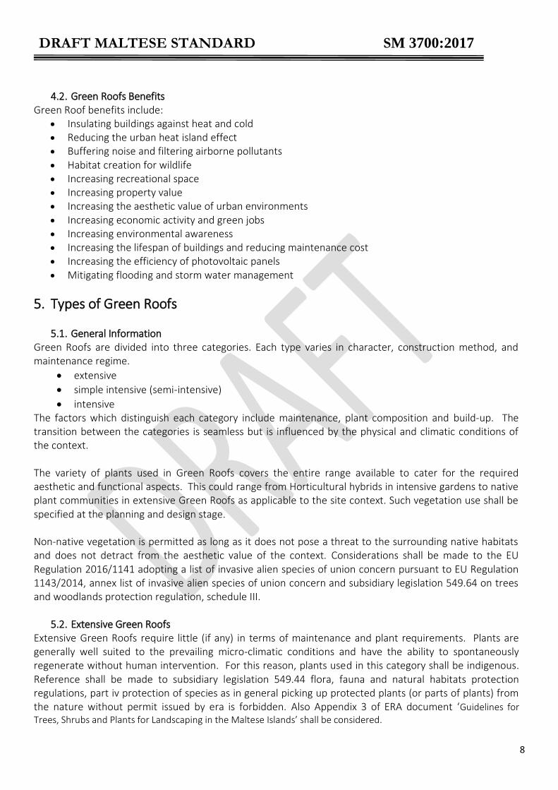
4.2. Green Roofs Benefits Green Roof benefits include:
Insulating buildings against heat and cold
Reducing the urban heat island effect
Buffering noise and filtering airborne pollutants
Habitat creation for wildlife
Increasing recreational space
Increasing property value
Increasing the aesthetic value of urban environments
Increasing economic activity and green jobs
Increasing environmental awareness
Increasing the lifespan of buildings and reducing maintenance cost
Increasing the efficiency of photovoltaic panels
Mitigating flooding and storm water management
5. Types of Green Roofs
5.1. General Information Green Roofs are divided into three categories. Each type varies in character, construction method, and maintenance regime.
extensive
simple intensive (semi-intensive)
intensive The factors which distinguish each category include maintenance, plant composition and build-up. The transition between the categories is seamless but is influenced by the physical and climatic conditions of the context. The variety of plants used in Green Roofs covers the entire range available to cater for the required aesthetic and functional aspects. This could range from Horticultural hybrids in intensive gardens to native plant communities in extensive Green Roofs as applicable to the site context. Such vegetation use shall be specified at the planning and design stage. Non-native vegetation is permitted as long as it does not pose a threat to the surrounding native habitats and does not detract from the aesthetic value of the context. Considerations shall be made to the EU Regulation 2016/1141 adopting a list of invasive alien species of union concern pursuant to EU Regulation 1143/2014, annex list of invasive alien species of union concern and subsidiary legislation 549.64 on trees and woodlands protection regulation, schedule III.
5.2. Extensive Green Roofs Extensive Green Roofs require little (if any) in terms of maintenance and plant requirements. Plants are generally well suited to the prevailing micro-climatic conditions and have the ability to spontaneously regenerate without human intervention. For this reason, plants used in this category shall be indigenous. Reference shall be made to subsidiary legislation 549.44 flora, fauna and natural habitats protection regulations, part iv protection of species as in general picking up protected plants (or parts of plants) from the nature without permit issued by era is forbidden. Also Appendix 3 of ERA document ‘Guidelines for Trees, Shrubs and Plants for Landscaping in the Maltese Islands’ shall be considered.

DRAFT MALTESE STANDARD SM 3700:2017
9
Plants used in this category of Green Roofs include grasses, herbaceous plants, herbs, bulbs and tubers. They are generally low-growing and exert little demand on the Green Roof build-up (e.g. depth is reduced refer to Table 4) and the structure in terms of weight.
5.3. Simple intensive Green Roofs Simple intensive or semi-intensive Green Roofs falls somewhere in-between intensive and extensive Green Roofs. Such Green Roofs require less maintenance depending on the types of vegetation used and the design objectives. Vegetation used in this category includes ground cover plants such as sedum, with grasses, perennials (herbaceous plants) and low growing shrubs/herbs (generally woody). These can be both native and non-native species depending on location and design concept but preference should be given to native species. The range of design and usage options available is limited when compared to intensive Green Roofs. Simple intensive Green Roof makes few demands on the layered structure and need little in terms of watering and fertilizing (if any) when compared to intensive Green Roof. Simple intensive Green Roof can be characterized by the vegetation forms given in Table 3.
5.4. Intensive Green Roofs This category is comparable with conventional gardens making use of a large variety of plants such as perennial shrubs and ground cover, grasses, bulbs, annuals and trees. These may be designed organically or formally depending on the desired design layout and at different heights. Intensive Green Roof makes heavy demands on the Green Roof build-up and requires regular maintenance, irrigation and fertilization. It also requires a structure able to support the additional loading. Although intensive greening covers the entire range of plants and design, limitations may occur when specifying trees and large shrubs in terms of the size of the rhizosphere and plant stability. Table 1 summarizes the key characteristics distinguishing between the three types of Green Roofs. Table 1 Types of Green Roofs and relative characteristics
Extensive Green Roof
Semi-intensive Green Roof
Intensive Green Roof
Substrate depth Shallow Medium Deep
Plant type Native Native/non-native Native/non-native Irrigation Low Low/medium Medium/high
Maintenance Low Low/medium Medium/high
Accessibility to roof No/infrequent Infrequent/regular Regular
From this point onwards, semi-intensive Green Roofs and intensive Green Roofs will be considered as having identical construction and performance characteristics requirements and characteristics unless otherwise indicated.

DRAFT MALTESE STANDARD SM 3700:2017
10
6. Planning of Green Roofs 6.1. Agents and requirements
The following agents shall be taken into consideration during the planning of Green Roofs:
Hydrological
Biological
Chemical
Live and Dead Loading
Static and dynamic loading
Wind Loading
Thermal Loading and radiation Requirements to be addressed by Green Roof systems and/or individual elements include:
Agronomic compatibility
Water infiltration and percolation (drainage)
Aeration
Water retention
Maintenance of the vegetation layer
Resistance to biological factors
Biodiversity and ecological value
Climatic/micro-climatic compatibility Other specific requirements may be requested subject to the design brief which is dependent on the context and intended use, such as sound proofing, run-off, and pollution control. To verify the performance of the designed Green Roof, it is necessary to conduct appropriate investigations and tests referring to applicable standards and certification.
6.2 Structural Requirements Structural requirements in relation to Green Roofs mainly refer to:
protection against falling
protection against root penetration
protection against damage to the waterproofing / root-resistant barrier
protection against sintering
drainage facilities
joints
protection against emissions
protection against lifting or excessive drag forces caused by the wind
fire characteristics
protection against slipping and shearing
edging
trafficable paved surfaces
furnishings
tree supports
6.3 Planning The performance of Green Roofs varies greatly depending on various factors such as vegetation type,

DRAFT MALTESE STANDARD SM 3700:2017
11
substrate composition and depth. For example, the insulation level of Green Roofs depends not only on the depth of the substrate but also on the type and habit of the vegetation being cultivated. The construction of a Green Roof is related to one or more of the following:
Amenity: A Green Roof can provide the setting for recreational space in both a domestic and commercial setting. The correct balance has to be achieved in relation to the area dedicated to the proposed activity and the area of greening. The vegetation proposed has to cater for the requirements of the activities expected taking into consideration aspects such as maintenance and construction methods. Amenity also relates to the visual amenity of the Green Roof as well as the sensory experience of the project.
Changes in the internal environment: The insulation benefits of the roof greening should not be underestimated and an effort has to be made to make sure that thermal insulation properties are adopted to increase the benefits of the system.
Increase the quality of the external environment: This refers to the effectiveness vegetation has in absorbing aerial pollution, to buffer noise, mitigate flooding and reduce ambient temperatures.
Providing habitats for wildlife and increasing ecosystem services: Green Roofs are a means of giving back (if only partially) to nature what has been taken away due to urbanization. Providing habitats for wildlife will benefit the urban population through ecosystem services thus increasing the quality of life in urban areas.
6.4 Site Analysis
Site analysis is carried out to understand the physical and climatic characteristics of the context. This analysis will identify the variables which would influence most of all, the type of vegetation to be specified and cultivated on the greened roof. Plants are particularly sensitive to the micro-climate of the site in question of which solar radiation, light intensity, temperature, shade, humidity levels, salinity levels and exposure to wind are the main (although not all) decisive factors for their survival. Understanding the cycles of the micro-climate is crucial for the success of the design. It is to be considered that the more one veers away from the optimum growing condition of plants, the more energy is required to succeed in the cultivation of the vegetation. This holds true for both the construction stage and the maintenance stage.
Particular attention must be given not only to exposure to sun but also to any reflective surfaces such as glazed elevations and walls. These cause changes to the intensity of solar radiation and/or shaded areas. The shading effects of the proposed planting and/or any existing vegetation must also be taken into account.
Winds produce significant stress on plant species. As a consequence, it is important to consider the plants’ habit, the characteristics of the canopy, the anchoring of the root-ball and the fragility of the branches. Adjacent buildings and structures would also need to be considered when analysing the effects of wind as they can create eddies and vortices which could affect plant survival and development. As a result, it would be opportunistic to consider the need for permanent or temporary anchoring systems.
Air emissions and/or fumes from equipment and services: The wind emitted by cooling fans and extractor fans may cause rapid degradation to the canopy of plants. This could be mitigated by the use of evergreen plants with a dense canopy layer unless a solid or semi-permeable screening is installed. Damaged plant foliage can be masked by the use of a vegetative screen adjacent to the latter plants.
Exposure to Salinity: Salt particles in the air may cause degradation of plant species. The possible use of plant species with strong resistance to salt should be considered. Damage to plants by salt

DRAFT MALTESE STANDARD SM 3700:2017
12
could happen to both the leaf surface and the substrate.
Heavy dust accumulation can also damage plants. It is essential that dust is periodically washed away from the leaf surface.
Planned plant species should be evaluated with those found growing within the context of the project.
It is important to take into account, any possible changes which could happen by time within the context which could affect any of the above factors as well as others not mentioned above.
6.5 Certification of the structure Prior to the commencement of the planning, designing and constructing stages of the Green Roof, the building and roof in question shall be certified suitable to withstand the loading imposed by the Green Roof and other related engineering aspects in connection to the Green Roof. This certificate shall be issued by a suitably qualified engineer. Structural alterations/redesigning might be required for the building and/or roof to be able to withstand the Green Roof. Restrictions might arise in the installation of certain types of Green Roofs.
6.6 Access and use of Green Roofs Areas designated for use by people shall be safe to use and access. Footpaths and paved areas shall be provided. Turfed (grassed) areas purposely planted for human traffic is acceptable although consideration must be given to elevated use of resource and maintenance requirements. Where Green Roofs need to be accessed for works as defined by Act XXVII/2000, compliance with obligations as outlined in same Act needs to be ensured. Planted areas are generally not suitable for public use. In extensive Green Roofs, access is normally restricted to maintenance and servicing.
6.7 Roof falls Where roofs are generally flat, the pitch of the roof, or falls, shall be considered for both structural and plant requirements. The benefits of efficient and proper roof gradients cannot be overstressed to avoid damage to plants and structural integrity. For extensive and intensive Green Roofs, the pitch shall be of a minimum gradient of 2%. Table 2 provides conversion information from percentage to degrees and ratios for roof falls. Roofs with falls of less than 2% shall require measures for improving drainage to avert ponding in the vegetation substrate and water-proofing membrane. (Ponding can lead to plant failure, change in vegetation type and damage to the damp proofing). As the pitch increases, special measures shall be required to protect the Green Roof structure against shear and slide. Roofs which have gradient in excess of 50% Green Roofs shall not be considered due to possible complications.

DRAFT MALTESE STANDARD SM 3700:2017
13
Table 2 Conversion table percentage roof slope to gradient in degrees to gradient as ratio
1% ≈ 0.6° ≈ 1:100
2% ≈ 1.1° ≈ 1:50
3% ≈ 1.7° ≈ 1:33.3
5% ≈ 2.9° ≈ 1:20
7% ≈ 4.0° ≈ 1:14.28
9% ≈ 5.1° ≈ 1:11.11
10% ≈ 5.7° ≈ 1:10
15% ≈ 8.5° ≈ 1:6.6
20% ≈ 11.3° ≈ 1:5
30% ≈ 16.7° ≈ 1:3.33
40% ≈ 21.8° ≈ 1:2.5
60% ≈ 31.0° ≈ 1:1.67
80% ≈ 38.7° ≈ 1:1.25
100% ≈ 45.0° ≈ 1:1
6.8 Roof designs and suitability for Green Roofs
Roof construction, physical conditions and micro-climate shall be considered when planning the construction of a Green Roof. Consideration shall be given to the materials used and features included in the construction and make-up of the roof which might in some way influence the success of the Green Roof.
6.8.1. Non-ventilated roofs with or without thermal insulation There are no restrictions in the type of Green Roof permissible on such roofs and form of vegetation used even those with high design loads. The load bearing capacity of the insulation needs to be adapted to the loads of the Green Roof structure including plants.
6.8.2. Non-ventilated roofs with thermal insulation on lightweight structures Considering that shallow substrates are not appropriate due to high solar radiation and the safety margin in lightweight roof with a low load-bearing capacity is low, Green Roofs are not advised unless the manufacturer provides the necessary guarantees.
6.8.3. Ventilated roofs with thermal insulation Note should be taken of the poor load-bearing capacity of the top layer. The cooling effect of Green Roofs can affect the physical construction of the building. This risk needs to be assessed on a site-by-site basis.
6.8.4. Inverted roofs Where Green Roofs are constructed on inverted roofs or other specially-shaped roofs fitted with thermal insulation above the waterproofing, attention needs to be paid to moisture diffusion. Each site will have to be assessed to see whether levelling and ventilation is required. Other measures may need to be employed following refurbishment of the roof.
6.9 Water tightness and damp-proofing Existing roof structures on which a Green Roof is to be constructed must be tested during the planning stage for water tightness. Where bituminous membranes are being used it is advised that more than one layer of membrane is laid at 90° to each other.

DRAFT MALTESE STANDARD SM 3700:2017
14
Consideration has to be given to the type of damp proofing utilized. Damp proof membranes shall be certified for suitability in a Green Roof construction.
6.10 Design loads The Green Roof should be constructed according to the load bearing capacity of the retaining structure. When deciding the maximum permissible loading, all Green Roof layers must be considered, at maximum water capacity and including the surface load generated by the vegetation, as a component of the surface load (refer to Table 3). The load generated by any water stored in an integral reservoir will also need to be added into the figures. Point loadings generated by large bushes, trees and structural components, such as pergolas, water features and peripheral items, will need to be calculated separately. Table 3 Design loads of various vegetation types (adapted from FLL 2008)
Vegetation type Design loads
KN/m2 Kg.m2
Extensive vegetation Sedum / herbaceous planting Herbaceous planting Grasses Grass and herbaceous planting
0.10 0.10 0.10 0.10
10 10 10 10
Simple-intensive vegetation Grasses Herbaceous plants Shrubs (to 150cmH)
0.15 0.15 0.20
15 15 20
Intensive vegetation Grass Low perennials Shrubs (to 150cmH) Shrubs over 150cm Shrubs up to 300cm Large shrubs1 up to 600cm Small trees1 up to 10m Trees up to1 15m
0.05 0.10 0.25 0.20 0.30 0.40 0.60 1.5
5
10 25 20 30 40 60
150 1 Loading calculated within the drip line of individual plants
Where planting is required and spot loads are generated, it is particularly important to ensure that the thermal insulation in conjunction with the waterproof membrane have adequate compressive strength. Where a layered structure is constructed, care must be taken to ensure that any temporary storage of materials does not push the load above the design limits.
6.11 Health and Safety Measures In connection with preparation and planning of a Green Roof, prior to commencement, the personnel involved (according to their respective responsibilities at law) shall ensure that all necessary conditions and precautions are in place to ensure a safe and healthy environment during the design and execution stages. Adequate measures are to be put in place to ensure the safe maintenance and use (enjoyment) of the Green Roof once constructed. A health and safety practitioner may be consulted, where required, to assist duty holders in ensuring such criteria. Typical risks associated with Green Roofs include, but are not limited to; falls from heights, use of

DRAFT MALTESE STANDARD SM 3700:2017
15
equipment, chemical and biological hazards and manual handling of heavy objects. Adequate (site specific) measures need to be taken to ensure that such risks are eliminated or reduced to an acceptable level. Failure to evaluate properly risks on site may result in bodily injury and/or death.
Attention must be paid to laws and regulations governing occupational health and safety, amongst others Act XXVII/2000, LN 44/2002, LN 36/2003 and LN 281/04. For avoidance of doubt, in terms of LN 281/04 the installation of a Green Roof shall be denoted as a construction activity and all applicable requisites of LN 281/04 shall be required.
6.11.1 Working at Heights The construction and/or maintenance of Green Roofs may expose workers to the risks of falls from heights. In principle, work at a height must be carried out only with appropriate equipment or using collective protection devices such as cradles, platforms or safety nets. Solid cradles need to be sufficiently high and have at least an end-board, a main handrail and an intermediate handrail or an equivalent alternative. If the use of such equipment is not possible because of the nature of the work, suitable means of access must be provided and safety harnesses or other anchoring safety methods must be used. The selection of the measures adopted shall be taken on the basis of the general principles of prevention (hierarchy of controls) laid out in Act XXVII/2000. The responsibility for the protective measures lies with the client, the project supervisor, the contractors and workers, each with their respective responsibilities at law.
6.12 Draining Arrangements for water drainage shall comply with the requirements laid down in BRO Technical Guidance Part F. Care must be taken during the initial planning of Green Roofs to ensure that there are proper facilities available for draining water away from all areas, whether or not they have been subjected to vegetation. Drainage must be available as part of the layered structure of the Green Roof as well as on other hard landscaped surfaces. Two arrangements can be used to drain excess water off the roofs efficiently, these include:
Having a drainage system separately for the vegetated areas and non-vegetated areas
Having a common drainage system for both vegetated and non-vegetated areas. Regardless of the size of the roof surface, drainage facilities located within the vegetation area must have at least one runoff facility and at least one emergency overflow. Runoff facilities and emergency overflows are to be designed in accordance with MSA EN 12056–3. The following standards shall be used to calculate the rate of flow of rainwater to be drained away from a roof under steady state conditions gravity drainage systems inside buildings EN 12056–3 and DIN 1986–100.
The coefficient of discharge of the Green Roof system proposed shall be established and applied to the

DRAFT MALTESE STANDARD SM 3700:2017
16
design of the drainage system to establish the appropriate sizing of the drains.
The methods used for draining a roof must be seen to on a case-by-case basis and should be also in accordance with BRO Technical Guidance Part F.
6.13 Irrigation The irrigation requires at least one water connection at roof level. The number of pipes, connections and the necessary water pressure will depend upon the location and structure of the building. The size, layout and species used will also determine the overall layout of the irrigation system. The design of the irrigation system should be factored in during the planning stages of the Green Roof.
6.14 Compatibility of materials All materials used for the roof and vegetation structure have to be selected in a way to ensure mutual chemical compatibility. Note: The material manufacturers generally provide information relating to any limitation of use due to incompatibility. If any material is found to be incompatible, either the selection must be revised or an additional barrier layer will have to be installed. Waterproof membranes and root-resistant membranes must be checked to ensure that they are resistant to hydrolysis. The materials will also have to be checked to ensure that they are suited to constant exposure to water as a result of greening applied over the top of them and, where necessary, verification should be supplied. There must be no risk of these functions being compromised by changes brought about by the biological action of micro-organisms and plants or by substances dissolved in the water. It shall be noted that some products used in certain areas fall within the Construction Products Regulation and are covered by European harmonised standards. These products shall bear the CE mark and the manufacturer or importer shall supply the declaration of performance. In some cases, (as per CPR) the technical documentation shall also be made available. This needs to be considered by the planner and contractor during the tendering and construction process.
6.15 Environmental compatibility The materials which are used must not be allowed to generate water and atmospheric pollution due to processes such as leaching or the release of gaseous substances. In addition, materials used in both the implementation and post-implementation phases should not leach or release any substances which could contaminate surface water run-off, water storage facilities and other water bodies. Attention must be paid to laws and regulations governing pollution and environmental compatibility.
6.16 Phytotoxicity and harm to fauna Materials must not contain any components which are harmful to flora and fauna. If phytotoxicity is suspected, plant germination testing and/or testing for phytotoxic substances, will have to be carried out.
6.17 Green Roof – End-of-Life Scenarios

DRAFT MALTESE STANDARD SM 3700:2017
17
End-of-life considerations for Green Roofs reflect the need to dismantle the Green Roof at one point in its lifetime. Various end-of-life options can be considered including:
Reuse of vegetative material
Disposing of Green Roof materials in authorised landfills
Reuse of materials/components of the Green Roof system
Recycling of materials/components of the Green Roof system Factors and issues affecting the end-of-life to be considered include:
The design for disassembly and reuse
The potential for recycling of materials
The assessment of the whole life cycle The practical implementation and the feasibility of these options depend on the detailing used in the construction and installation of the Green Roof. Specific components of the Green Roof can be considered for recycling. This requires selective dismantling and the classification of components or waste materials for potential reuse. General considerations need to be assessed through a comprehensive assessment with reference to the sustainability of Green Roofs. A whole life cycle assessment and a life cycle cost analysis facilitate the decision making process including the end-of-life stage. The assessment needs to be carried out with reference but not limited to the following: Green Roof system and components (materials analysis), Green Roof contribution to building sustainability, time of dismantling and disassembly, cost implications, transport of components, storage of components, identification of structure / structures for reuse options, technological limitations of the old Green Roof system, health and safety considerations, structural system implications.
7. Materials and Components 7.1 Green Roof layers
A typical Green Roof (refer to Figure 1) consists of the following layers:
vegetation
vegetation support layer
filter layer
drainage layer
protective layer
root-resistant barrier In some case the following layers may be required between the water-proofing membrane and the root resistant barrier.
separation layer
anti-bonding layer

DRAFT MALTESE STANDARD SM 3700:2017
18
1 Roof slab with damp proof layer 2 Root resistant barrier 3 Protection layer 4 Drainage layer 5 Filter fabric 6 Vegetation support layer 7 Vegetation
7.2 Depth of Green Roofs The depth of the layered structure will depend upon:
the way in which the roof is constructed;
the type of vegetation planned for the site;
the materials used in the individual courses. Table 4 lists the various layer depths for different types of vegetation. The following factors need to be taken into account when determining the depth of the substrate and drainage layer:
the properties of the substrate
the properties of the drainage layer
the vegetation requirements
the exposure of the roof surface
the microclimatic conditions
the specific surface loadings of the materials used
the desired water retention
the load bearing capacity of the roof structure
the pitch of the roof In addition, when planning the functional layers, the following aspects shall be taken into account:
• with the increasing depth of the substrate a differentiation has to be made in regard to the organic content;
• shallow substrates dry up quicker especially in the dry season necessitating more watering; • shallow substrates inhibit plant growth and can be the cause of premature plant death; • the pitch of the roof, to avoid standing water in thinly layered constructions; • special types of construction have to meet structural and vegetation requirements.
7.3 Vegetation
There are no limits as to which species to use on Green Roofs as long as the physical characteristics of the roof are considered. Characteristics include; orientation, degree of solar radiation and exposure to wind.
Figure 1 – Green Roof Stratification
DRAFT MALTESE STANDARD SM 3700:2017
19
Other factors to be considered include the availability of irrigation water and maintenance issues. More than in traditional gardens, it needs to be understood that in Green Roofs, the type of plants selected have to be compatible with the type of substrate used and the irrigation regime. It shall be taken into consideration that, for example, certain Mediterranean plants are sensitive to high humidity levels in the substrate which could lead to plant failure. The use of invasive alien species shall not be permitted in line with the UN Convention on Biological Diversity, the EU IAS regulations and the Subsidiary Legislation 549.44 Flora, Fauna and Natural Habitats Protection Regulations. Due consideration must be given to the volume of water used for irrigation to meet the plant species requirements and in all cases preference should be given to those plants that require less water.
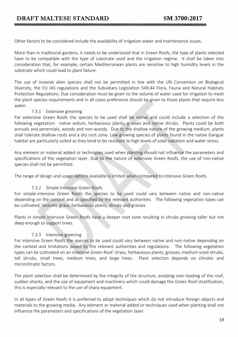
7.3.1 Extensive greening For extensive Green Roofs the species to be used shall be native and could include a selection of the following vegetation: native sedum, herbaceous plants, grasses and native shrubs. Plants could be both annuals and perennials, woody and non-woody. Due to the shallow nature of the growing medium, plants shall tolerate shallow roots and a dry root zone. Low growing species of plants found in the native Garigue habitat are particularly suited as they tend to be resistant to high levels of solar radiation and water stress. Any element or material added or techniques used when planting should not influence the parameters and specifications of the vegetation layer. Due to the nature of extensive Green Roofs, the use of non-native species shall not be permitted. The range of design and usage options available is limited when compared to intensive Green Roofs.
7.3.2 Simple Intensive Green Roofs For simple-intensive Green Roofs the species to be used could vary between native and non-native depending on the context and as specified by the relevant authorities. The following vegetation types can be cultivated; Sedums, grass, herbaceous plants, shrubs and grasses. Plants in simple intensive Green Roofs have a deeper root zone resulting in shrubs growing taller but not deep enough to support trees.
7.3.3 Intensive greening For intensive Green Roofs the species to be used could vary between native and non-native depending on the context and limitations posed by the relevant authorities and regulations. The following vegetation types can be cultivated on an intensive Green Roof: Grass, herbaceous plants, grasses, medium sized shrubs, tall shrubs, small trees, medium trees, and large trees. Plant selection depends on climatic and microclimatic factors. The plant selection shall be determined by the integrity of the structure, avoiding over-loading of the roof, sudden shocks, and the use of equipment and machinery which could damage the Green Roof stratification, this is especially relevant to the use of sharp equipment. In all types of Green Roofs it is preferred to adopt techniques which do not introduce foreign objects and materials to the growing media. Any element or material added or techniques used when planting shall not influence the parameters and specifications of the vegetation layer.

DRAFT MALTESE STANDARD SM 3700:2017
20
When planting vegetation or laying turf, the type of growing medium utilised by the supplier shall be considered as problems may arise in the growing of the roots into the Green Roof substrate. The levels of clay and organic matter of the introduced media shall not exceed 20% and 35% respectively from that found in the Green Roof substrate. Table 4: Indicative minimum substrate depths for different types of plant types.
Type of Greening and Vegetation Minimum depth of the Vegetation Support Course (cm)
10 15 20 25 30 35 40 45 50 100 150
Extensive Greening
Sedum
Herbaceous plants
Grasses
Selected native Shrubs
Simple Intensive Greening
Grass
Herbaceous Plants
Shrubs
Grasses
Intensive Greening
Grass
Herbaceous plants
Grasses
Medium height shrubs
Tall shrubs
Small trees
Medium size trees
Large Trees
Data taken from the LifeMedGreenRoof project
Sedum Sedums are a large genus of flowering plants in the family Crassulaceae, members of which are commonly known as stonecrops (eg Sedum sediforme)
Grass Monocotyledonous plants grown as lawn (eg Cynodon dactylon, Festuca species etc)
Herbaceous plants
Herbaceous plants are plants that have no persistent woody stem above ground. They may be annuals, biennials or perennials (eg. Dicondra repens, Lobularia maritima)
Grasses Monocotyledonous flowering ornamental grasses grown for aesthetic and/or functional characteristics and not cut as lawn (eg Festuca glauca, Hyparrhenia hirta)
Shrubs A shrub is a small to medium-sized woody plant distinguished by its multiple stems and shorter height (eg Santolina chamaecyparissus., Teucrium flavum. etc)
Trees A tree is a perennial plant with a distinct trunk, supporting branches and leaves (eg Olea europaea)
7.3.4 Other considerations
During planting, the root ball shall fit within the thickness of the growing medium in which it is to be set. The root ball shall never be placed directly on the filter fabric, or on the protection layer of the waterproofing membrane or root barrier.
DRAFT MALTESE STANDARD SM 3700:2017
21
It is important that any anchoring system does not interfere with the functioning of the Green Roof system in its integrity. Such anchoring systems shall be considered during the design stage of the Green Roof. It must be taken into account that a shallow substrate would limit plant development and could be the cause of premature plant failure.
7.4 Vegetation support layer (Also referred to as substrate / growing media)
Refer to Table 8 and
DRAFT MALTESE STANDARD SM 3700:2017
22
Table 9
Use of machinery for the preparation of the growing media as normally practiced in ground level gardens is generally excluded on Green Roofs. Such methods could damage the underlying layers compromising the integrity of the Green Roof system including the water proofing. The Green Roof substrates must be prepared in a controlled system from beforehand. It is best that the growing media is manufactured in areas which eliminate the possibility of the introduction of foreign materials during manufacture and packaging. Normal techniques as in traditional gardens are adopted in the planting of Green Roofs.
7.4.1. Components The vegetation support layer builds the basis for the plant growth and shall allow good root penetration. It shall have all the requisite basic physical, chemical and biological properties:
i. lightness, especially at the maximum water retention capacity, when structural problems may be a problem;
ii. high water retention capacity and sufficient aeration capacity when saturated, to allow sufficient accumulation of water to meet the water needs of plants;
iii. high permeability; iv. stability (maintenance over time of the initial physical properties) v. adequate particle size distribution to obtain the required hydrological characteristics, with low
presence of very fine material; vi. sufficient presence of organic matter to permit the formation of a stable ecosystem, but not
high in order to avoid excessive structural alterations and reduce any fire hazards; vii. not excessively alkaline or acidic; viii. moderate salinity;
ix. significant cation exchange capacity (CEC) to assure nutrients level; x. absence of phytotoxic components, pollutants and weed seeds.
Natural soil is not adequate to support vegetation on a Green Roof, while a specific engineered mix composed by a higher percentage of mineral compounds and a lower percentage of organic compounds may satisfy such performance. The specific substrate to be used shall meet the local construction requirements and the specific objectives for the vegetation. Construction requirements relate to:
i. the drainage function; ii. the design load; iii. the protective function.
Objectives for the vegetation relate to:
i. the demands imposed by the desired greening type and the vegetation; ii. ensuring all functions are long-lasting; iii. limiting the maintenance and plant development costs.
In a layered structure where the depth of the vegetation support course is 35cm or greater, a distinction can be made between an upper substrate and a lower substrate; the lower substrate could contain less organic material, have lower water retention and higher drainage capacity.

DRAFT MALTESE STANDARD SM 3700:2017
23
7.4.2. Requirements
Attention shall be paid mainly to the following properties depending upon the type of Green Roof which is being undertaken, in respect to the vegetation support courses:
i. particle size distribution ii. compressibility (compaction property) iii. total porosity iv. water permeability v. water retention/available water vi. air content capacity at maximum water retention
vii. water retention curve viii. dry bulk density and saturation weight
ix. organic matter content x. pH value xi. salt content xii. adsorptive capacity (CEC)
xiii. nutrient content xiv. plant compatibility / risk of phytotoxicity xv. environmental compatibility xvi. seed germination / regenerative plant parts
xvii. frost resistance xviii. commercial volume (fresh bulk density)
Where reference testing methods are not included, appropriate methodology is described in APPENDIX B. Alternative methods may be used, but detailed description and comparability with the reference methods shall be provided.
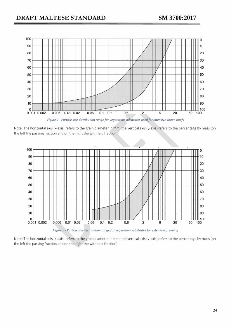
7.4.3. Particle size distribution The standard test method for the determination of the particle size distribution is MSA EN 15428:2007. The combined clay and silt content (d < 0,063 mm) in vegetation courses should not exceed the following values:
for intensive greening: 20 % by mass;
for extensive greening: 15 % by mass. The grading curves for vegetation substrates should be as shown in Figure 2 and Figure 3 below. These particle size distribution areas are just an orientation aid and the functional requirements reported in Note: The horizontal axis (x-axis) refers to the grain diameter in mm; the vertical axis (y-axis) refers to the percentage by mass (on the left the passing fraction and on the right the withheld fraction)
Table 5 are the decisive criteria evaluation.
DRAFT MALTESE STANDARD SM 3700:2017
24
Figure 2 - Particle size distribution range for vegetation substrates used for intensive Green Roofs
Note: The horizontal axis (x-axis) refers to the grain diameter in mm; the vertical axis (y-axis) refers to the percentage by mass (on
the left the passing fraction and on the right the withheld fraction)
Figure 3 - Particle size distribution range for vegetation substrates for extensive greening
Note: The horizontal axis (x-axis) refers to the grain diameter in mm; the vertical axis (y-axis) refers to the percentage by mass (on
the left the passing fraction and on the right the withheld fraction)

DRAFT MALTESE STANDARD SM 3700:2017
25
Table 5 - The appropriate coordinates
grain particle size
mm
range for extensive
% m/m
range for intensive
% m/m
fraction < 0.05 0-15 0-18
fraction < 0.15 0-18 2-26
fraction < 0.25 0-21 5-33
fraction < 0.50 0-27 7-46
fraction < 1.00 0-42 14-62
fraction < 2.00 18-60 24-80
fraction < 5.00 49-95 53-100
fraction < 10.00 75-100 80-100
fraction < 16.00 92-100 100
fraction < 20.00 100 100
Note: a tolerance of 10% is permitted only for a single fraction/sample
7.4.4. Water permeability / saturated hydraulic conductivity For the determination of water permeability and saturated hydraulic conductivity refer to DIN 18035-4 and ASTM F 1815-11. Water permeability in vegetation substrates shall be adjusted to suit the type of construction planned for the drainage course. Values for intensive and extensive Green Roofs should be ≥ 5 mm/min for substrates once they have been compacted. The recommended permeability value shall not exceed 70 mm/min
7.4.5. Compaction (volume reduction by compaction) The standard test method for compaction is described in APPENDIX B.
The volume reduction by compaction must be declared in % by volume. Generally, this value is approximately 10% by volume. This value may be determined during the preparation of the permeability test (ref. to DIN 18035-4) Vegetation substrates composed of aggregate mixtures must have adequate structural and bedding strength. This is essentially determined by the particle size distribution and the grain shape. Therefore, crushed granular material shall be used for structural characteristics. This applies in particular to extensive Green Roofs. In order to exclude a claim for defects, the amount of settling permitted once construction work has been completed as a result of; the weight of the structure, the effects of water, biological processes or loads applied during maintenance of the site, should be as shown below:
with layer depths up to 50 cm, no more than 10% of the nominal depth;
with layer depths of over 50 cm, no more than an average of 5 cm.

DRAFT MALTESE STANDARD SM 3700:2017
26
7.4.6. Bulk density, porosity, water storage capacity and air capacity The standard test method used for the determination of these physical properties is MSA EN 13041:2011.
The Porosity shall be more than 60% (by volume), to ensure an adequate volume of water retention, and less than 75% (by volume). The Dry Bulk Density (kg/m3) is necessary to calculate the volume weight at maximum water capacity. Moreover, when considering the climatic condition of the Maltese Islands, the dry bulk density must be > 600 kg/m3. The Maximum Water Capacity (% v/v) is determined at pF 0.7 (tension corresponding to -0,005MPa). The Volume Weight at Maximum Water Capacity (kg/m3) is calculated as follows:
𝑉𝑜𝑙𝑢𝑚𝑒 𝑤𝑒𝑖𝑔ℎ𝑡 𝑎𝑡 𝑀𝑎𝑥𝑖𝑚𝑢𝑚 𝑊𝑎𝑡𝑒𝑟 𝐶𝑎𝑝𝑎𝑐𝑖𝑡𝑦 = 𝐷𝑟𝑦 𝐵𝑢𝑙𝑘 𝐷𝑒𝑛𝑠𝑖𝑡𝑦 + (10 ∗ 𝑀𝑎𝑥𝑖𝑚𝑢𝑚 𝑊𝑎𝑡𝑒𝑟 𝐶𝑎𝑝𝑐𝑖𝑡𝑦) Example:
dry bulk density: 500 kg/m3
maximum water capacity: 60 % v/v
volume weight at maximum water capacity = 500 + [10 x 60] = 1,100 kg/m3
Volume weight at maximum water capacity may be also declared as mass by surface for every 10 cm of
depth (kg/m2).
Example:
volume weight at maximum water capacity = 1,100 kg/m3
volume weight at maximum water capacity for 10 cm of depth = 110 kg/m3
When the vegetation substrate is at full water capacity, air capacity shall be not less than 10% (by volume); if this value is lower, then the air content at pF 1.0 (-0,001 MPa) shall be determined and it shall be at least 15% (by volume). Available water for plants (% v/v) is a very important property for a Green Roof substrate; it is defined as the water content between pF 0.7 (maximum water capacity) and pF 4.2 (-1,5 MPa = conventional wilting point - when the residual presence of water is considered not available for plants). To determine water content at pF 4,2 the sand box test (MSA EN 13041) shall not be applied, so alternative methods1 such as those found in ASTM D 6836. Result shall be expressed as volumetric percentage, so the percentage by weight value shall be multiplied by the dry bulk density value and divided by 100. Available water may be expressed also as l/m2 for every 10 cm of depth: the formula used is as above for the volume weight property (volumetric available water is divided by 10 to have l/m2 every 10 cm of depth). An approximate value of this parameter may be obtained subtracting from the maximum water capacity a portion of around 10 - 15 % (estimated value of water content at pF 4.2 for mineral growing media).
1 Could also refer to the Italian Ministerial Decree-Ordinary Supplement N. 173 met.5

DRAFT MALTESE STANDARD SM 3700:2017
27
A complete water retention curve for the dynamic of available water may be useful; for this curve the water content shall be determined at least at the following tension points:
pF 0.7 (-0.005 MPa);
pF 1.0 (-0.001 MPa);
pF 2.0 (-0.01 MPa);
pF 2.7 (-0.05 MPa);
pF 3.4 (-0.25 MPa);
pF 4.0 (-1 MPa);
pF 4.2 (-1.5 MPa).
7.4.7. Organic matter content The standard test method used for the determination of organic matter content is MSA EN 13039. Organic matter is an important component in the growing media. Organic matter influences the water retention, the cation exchange capacity (CEC), and the microbial metabolism. Organic matter is an unstable component (due to mineralization processes) and its presence in the mix must be low and under control. The organic matter content shall be as shown below:
for intensive Green Roof: ≤ 80 g/l
for extensive Green Roof: ≤ 60 g/l The suggested analytical method provides results as percentage by weight (% m/m); to get the volumetric value (g/l), result shall be multiplied for the dry bulk density value (kg/m3) and then divided by 100.
𝑂𝑟𝑔𝑎𝑛𝑖𝑐 𝑀𝑎𝑡𝑡𝑒𝑟 𝐶𝑜𝑛𝑡𝑒𝑛𝑡(𝑔/𝑙) = 𝑂𝑟𝑔𝑎𝑛𝑖𝑐 𝑀𝑎𝑡𝑡𝑒𝑟 𝐶𝑜𝑛𝑡𝑒𝑛𝑡(%𝑚/𝑚) × [𝐷𝑟𝑦 𝐵𝑢𝑙𝑘𝐷𝑒𝑛𝑠𝑖𝑡𝑦
100]
If the growing media contains stable carbonaceous material (such as biochar) an adjustment may be needed, as specified below:
the manufacturer shall declare the presence of such carbonaceous material;
this material shall be tested for the determination of its total volatile substances (MSA EN 13039 at 550 °C) and of the molar ratio H:C (Dumas method);
if the molar ratio H:C of the material is ≤ 0.7, than to the determined organic matter content value of the substrate a quote of the volatile substance of the carbonaceous material shall be subtracted (proportionally to the rate present in the substrate);
if the molar ratio H:C of the carbonaceous material is > 0.7, the value of organic matter content of the substrate is confirmed.
7.4.8. pH value
The standard test method used for the determination of the pH value is MSA EN 13037. The pH value of the growing media has to be considered in combination with the needs of the vegetation. For both extensive and intensive greenings, it should be between 5.5 and 8.8 (pH unit). Accounting for the demands of the vegetation any drop in pH value in the substrate below the admissible range after the installation shall be avoided. Special forms of vegetation, such as special humus rooting plants, may need a lower pH value (4.0-5.5).

DRAFT MALTESE STANDARD SM 3700:2017
28
7.4.9. Electrical conductivity (salt content index) The standard test method used for the determination of the pH value is MSA EN 13038 (water extraction 1:5). Before installation, the electrical conductivity (index of the content of soluble salts) of the growing media shall not exceed the values shown below:
for intensive greening: 60 mS/m
for extensive greening: 50 mS/m
With regard to the potential risk of environmental pollution due to the leaching of salts such as nitrate or phosphates, the aim should be to achieve the lowest possible salt levels. The maximum value of electrical conductivity after installation may not exceed 70 mS/m (for both extensive and intensive greenings).
7.4.10. Cation Exchange Capacity (Adsorptive capacity) The standard test method used for the determination of the Cation Exchange capacity is ISO 13536:1995. However alternative methods are defined in ISO 14254:2001 and ISO 11260:1994. The Cation exchange capacity (CEC) is a very important property for a growing media; the higher the value, the higher is the capacity to adsorb nutrients. CEC values shall be as shown below
for intensive greening: > 12 meq/100 g
for extensive greening: > 8 meq/100 g
The method for the direct measurement of the CEC may sometimes provide negative results. Suggested test method (calculated CEC) is to add to the total acidity value the quote of exchangeable cations (Ca, Mg, K, Na).
7.4.11. Nutrient contents The standard test method used for the determination of the pH value is EN 13038 (water extraction 1:5).
The nutrients content in vegetation substrates needs to be kept as low as possible and shall not exceed the levels set out in Table 6:
Table 6 - Nutrient contents limits
Element Content
N ≤ 250 mg/l substrate
P ≤ 90 mg/l substrate
K ≤ 300 mg/l substrate
Ca ≤ 350 mg/l substrate
Mg ≤ 120 mg/l substrate
Na ≤ 120 mg/l substrate Note: N = N-NO3 + N-NH4

DRAFT MALTESE STANDARD SM 3700:2017
29
If the electrical conductivity (salt content) value is in the recommended range, nutrients content may be not requested. Large reserves of nutrients should not be used due to the problem of leaching in the time between construction and greening. Any necessary additional nutrient supply by means of fertilizing should only be carried out after greening or during final care. For such purpose, additional fertilisation should be carried out according to the nutrients in the substrate and the greening objectives, better if certified by an agronomist. During initial and subsequent fertilising, it is recommended that nutrients be administered by means of coated NPK slow-release fertiliser capsules, not during rain falls, at the maximum annual rates as shown below (N:P:K = 1:0,5:1):
for intensive Green Roofs: 6 g N/m2
for extensive Green Roofs: 4 g N/m2
7.4.12. Plant compatibility/risk of phytotoxicity The standard test method to prove the absence of phytotoxicity of the growing media is MSA EN 16086-2. For the suggested tests (determination of plant response), the “vitality index” (calculated for the germination rate and the root length) shall result inferior to 65%
7.4.13. Contaminants (environmental aspects) To ensure the absence of environmental risks, heavy metal content values may be requested. The standard test method used is MSA EN 13650. The content of the main heavy metal that may be present in growing media shall not exceed the levels set out in Table 7:
Table 7 - Heavy metals limits
Element Content
Pb tot. ≤ 140 mg/kg s.s
Cd tot. ≤ 1.50 mg/kg s.s
Ni tot. ≤ 100 mg/kg s.s
Zn tot. ≤ 500 mg/kg s.s
Cu tot. ≤ 230 mg/kg s.s
Hg tot. ≤ 1.50 mg/kg s.s
Cr VI ≤ 0.50 mg/kg s.s
Eventually, for other metals or pollutants (organic compounds) in soil, the level in the growing media shall
not exceed the limits set out by local legislation.
7.4.14. Proportion of foreign substances The proportion of identifiable foreign substances over 6 mm in diameter (the shortest side is measured), e.g. wall and floor tiles, glass, ceramics, shall not exceed 0.5 % mass. The proportion of metals or plastics shall not exceed 0.3 % mass. Refer to standard test method UNI 10780 A.
7.4.15. Seed germination / regenerative plant parts The materials used initially to assemble the vegetation substrate should contain no living plants, nor any regenerative plant parts, particularly root weeds. During the preparation of vegetation substrates care shall be taken at all times to avoid the inclusion of seeds. In addition, vegetation substrates need similar

DRAFT MALTESE STANDARD SM 3700:2017
30
protection whilst they are being manufactured or stored.
7.4.16. Frost resistance The frost resistance of the mineral structural materials must be ensured by the manufacturer. The frost resistance requirements of aggregates for concrete, or of natural stone building materials are based on materials and components subjected to high levels of static and/or dynamic stress. There is only limited scope for including these requirements in an appraisal of roof greening materials in terms of the vegetation used.
Table 8 - Vegetation support requirements for extensive Green Roofs
Defined properties Requirements
particle size diameter < 0,063 ≤ 15 % m/m (also see distribution area)
compressibility declaration
water permeability 5-70 mm/min
total porosity 60-75 % v/v
dry bulk density > 600 kg/m3
maximum water capacity declaration
volume weight at maximum water capacity declaration
available water for plants declaration
organic matter content ≤ 60 g/l
pH 4.0-8.8 unit
electrical conductivity ≤ 50 mS/m m (≤ 70 mS/m after installation)
CEC (cation exchange capacity) > 8 meq/100 g
Pb tot. ≤ 140 mg/kg d.m.
Cd tot. ≤ 1.50 mg/kg d.m.
Ni tot. ≤ 100 mg/kg d.m.
Zn tot. ≤ 500 mg/kg d.m.
Cu tot. ≤ 230 mg/kg d.m.
Hg tot. ≤ 1.50 mg/kg d.m.
Cr VI ≤ 0.50 mg/kg d.m.
foreign substances over 6 mm in diameter ≤ 0.5 % m/m
metals or plastics ≤ 0.3 % m/m
optional properties requirements
N ≤ 250 mg/l substrate
P ≤ 90 mg/l substrate
K ≤ 300 mg/l substrate
Ca ≤ 350 mg/l substrate
Mg ≤ 120 mg/l substrate
Na ≤ 120 mg/l substrate
plant compatibility (vitality index) > 65%
commercial volume (fresh bulk density) declaration

DRAFT MALTESE STANDARD SM 3700:2017
31
Table 9 - Vegetation support requirements for intensive Green Roofs
7.5 Filter layer
7.5.1 Definition
The filter layer is designed to prevent fine particles from being washed out of the vegetation support layer into the drainage layer, thereby adversely affecting the water permeability therein.
7.5.2 Materials groups and types
Green Roofs make use of geo-textiles in the form of fleece or woven fabrics as filter layer. The filter layer is either laid on top of the drainage layer separately, or it forms an integral part of ready-made drainage matting. Fleece fabrics consist of aligned or randomly laid fibres of any length. These fibres may be bonded using a mechanical or thermal process, or a combination of both. The manufacturer shall guarantee that fleece fabrics are free from any foreign contaminates.
defined properties requirements
particle size diameter < 0,063 ≤ 20 % m/m (also see distribution area)
compressibility declaration
water permeability 5-70 mm/min
total porosity 60-75 % v/v
dry bulk density > 600 kg/m3
maximum water capacity declaration
volume weight at maximum water capacity declaration
available water for plants declaration
organic matter content ≤ 80 g/l
pH 4.0-8.8 unit
electrical conductivity ≤ 60 mS/m (≤ 70 mS/m after installation)
CEC (cation exchange capacity) > 12 meq/100 g
Pb tot. ≤ 140 mg/kg d.m.
Cd tot. ≤ 1.50 mg/kg d.m.
Ni tot. ≤ 100 mg/kg d.m.
Zn tot. ≤ 500 mg/kg d.m.
Cu tot. ≤ 230 mg/kg d.m.
Hg tot. ≤ 1.50 mg/kg d.m.
Cr VI ≤ 0.50 mg/kg d.m.
foreign substances over 6 mm in diameter ≤ 0.5 % m/m
metals or plastics ≤ 0.3 % m/m
optional properties requirements
N ≤ 250 mg/l substrate
P ≤ 90 mg/l substrate
K ≤ 300 mg/l substrate
Ca ≤ 350 mg/l substrate
Mg ≤ 120 mg/l substrate
Na ≤ 120 mg/l substrate
plant compatibility (vitality index) > 65%
commercial volume (fresh bulk density) declaration

DRAFT MALTESE STANDARD SM 3700:2017
32
7.5.3 Requirements The following characteristics (refer to Table 10) shall be taken into consideration when selecting the filter layer:
Environmental compatibility
Plant compatibility / risk of phytotoxicity
Fire characteristics
Density
Mechanical stress resistance
Effectiveness of mechanical filtration / aperture width
Susceptibility to root penetration
Resistance to weathering
Resistance to microorganisms
Resistance to chemicals
Tensile strength, elasticity, coefficient of friction
7.5.4 Density The recommended minimum density of the filter sheet ranges between 100 g/m2 and 200 g/m2 for substrates of up to 25 cm deep. For deeper substrates, it may be necessary to increase the density in order to meet the requirements of penetration resistance, tensile strength and elasticity, which will be determined by the materials used and by the type of structure involved. Manufacturer’s specifications shall be consulted.
7.5.5 Mechanical stress resistance Fleece fabrics shall have a penetration resistance of ≥ 1.1 kN as per MSA EN ISO 12236.
7.5.6 Effectiveness of mechanical filtration / aperture width The effectiveness of a fleece fabric in terms of mechanical filtration is characterised by the effective aperture width. The effective aperture width O90,w denotes the diameter of the grains of a standard soil test from which the geo-textile retains 90 % of the soil and allows 10 % to pass through. For Green Roofing purposes, the depth and composition of the substrate dictate that filter layers with an effective average aperture width from 0.06 mm ≤ O90,w < 0.2 mm are adequate.
7.5.7 Susceptibility to root penetration Fleece fabrics must permit root penetration. This is especially the case for extensive greening sites where the shallow construction depths necessitate the use of the drainage layer as a root accommodating layer.
7.5.8 Resistance to weathering Considering that fleece fabrics are not weather-proof, the manufacturer’s specifications for maximum outdoor storage times shall be noted.
7.5.9 Resistance to microorganisms The resistance to microbiological attack of the filter sheet shall comply with the requirements as per MSA EN 12225. The resistance to microbial agents shall be >80% of the initial state as per MSA EN ISO 13438.

DRAFT MALTESE STANDARD SM 3700:2017
33
7.5.10 Resistance to chemicals The proof of resistance to chemicals must be provided by the manufacturer. It is common practice to prove the longevity of the product for the length of use.
7.5.11 Resistance to oxidisation The residual Resistance to oxidisation shall be >80% of the initial state as per MSA EN ISO 13438.
7.5.12 Tensile strength, elasticity and coefficient of friction The Longitudinal Tensile strength shall be >7.0 kN/m, as per EN ISO 10319; The Transverse Tensile strength shall be >7.0 kN/m, as per EN ISO 10319; The Deformation following longitudinal tension shall be <35%, as per EN ISO 10319; The Deformation following transversal tension shall be <35%, as per EN ISO 10319.
7.5.13 Construction Filter layers shall overlap by a minimum of 10 cm and they shall extend to the vertical Green Roof edges just beneath the surface of the substrate. Filter layers shall not be exposed to the elements or be visible. The filter layers shall be covered immediately by the substrate. When this is not possible, the maximum time that the filter remains uncovered may not exceed the manufacturer’s specifications and shall be kept to a minimum. Uncovered filter layers shall be protected against negative wind pressures. Drainage matting lined with filter layers which are extended to the vertical Green Roof edges shall be provided with permanent weather proofing. Care must be taken to ensure that construction work does not result in a reduction of air space in the drainage layer at any point of the system. Table 10 - Performance specification for filter layer
Characteristics Reference to Standard
Unit of measurement
Reference values
Density g/m2 100-200 for substrates of up to 25 cm deep
Mechanical stress resistance penetration resistance
MSA EN ISO 12236 KN ≥ 1.1
effective average aperture width mm 0.06 ≤ O90,w < 0.2
Resistance to microorganisms MSA EN ISO13438 % >80
Resistance to oxidisation To be provided by manufacturer
Resistance to oxidisation MSA EN ISO13438 % >80
Longitudinal Tensile strength EN ISO 10319 kN/m >7.0
Transverse Tensile strength EN ISO 10319 kN/m >7.0
Deformation following longitudinal tension EN ISO 10319 % <35
Deformation following transversal tension EN ISO 10319 % <35

DRAFT MALTESE STANDARD SM 3700:2017
34
7.6 Drainage course 7.6.1 Definition
The drainage course shall contain sufficient cavities to facilitate the passage of any excess water. Provided that suitable materials are used, this course can also act as a water reservoir and it can both increase the space available for root growth and protect the underlying structure.
7.6.2 Materials groups and types A distinction is made between the following groups and types of drainage materials: Granular, natural and processed aggregates
gravel and fine chippings;
lava and pumice;
expanded clay and shale, broken and unbroken;
expanded slate, broken and unbroken. Granular, recycled aggregates
broken tiles;
foamed glass.
Drainage matting
structured fleece matting;
studded plastic matting;
woven fibre matting;
foam matting.
Drainage boards
studded rubber boards;
shaped rigid plastic boards;
shaped plastic foam boards.
Drainage and substrate boards
boards made from modified foam.
Selection of the drainage materials is dependent on structural requirements and objectives for vegetation.
Construction requirements of the drainage layer relate to:
the drainage function;
the design loads;
the protective function.
Objectives for the vegetation relate to:
the prevention of standing water;
water supply either through retention or from a reservoir;
increasing the depth of the course available for root penetration;
the type of vegetation.
The thermal characteristics of the drainage layer could be taken into consideration when calculating the U-value of the roof.

DRAFT MALTESE STANDARD SM 3700:2017
35
7.6.3 Requirements Where drainage courses are concerned, some or all of the following properties shall be taken into account, depending on the group of materials in use:
compatibility of materials
environmental compatibility
plant compatibility / risk of phytotoxicity
fire characteristics
granulometric composition
frost resistance
structure and layer stability
behaviour under compressive loads
water permeability
water-storage capacity / maximum water capacity
pH–value
salt content
7.6.4 Compatibility of materials All materials used within the Green Roof shall be compatible with each other. Such materials shall be chemically
compatible. The manufacturers shall be able to provide the necessary information related to any limitations of use
due to incompatibility.
In the event that materials are incompatible, the choice of materials have to be revised or additional layers installed
without changing or effecting the characteristics and function of the Green Roof system.
Any granular drainage material used should be checked to ensure that they are suitable for the intended use without
the risk of degradation due to constant exposure to water or biological action of micro-organisms and/or by dissolved
substances in the water.
7.6.5 Environmental compatibility Materials shall not be allowed to generate pollution through leaching and/or as gaseous substances. National and
European legislation shall be referred to. Subsequent disposal and recycling requirements shall be considered when
selecting materials.
7.6.6 Plant compatibility Materials and substances used shall not prove harmful to plants and other wildlife. If phytotoxicity is suspected, tests
shall have to be carried out.
7.6.7 Fire characteristics Both granular and geosynthetic drainage layers shall not be composed of flammable materials or pose as a fire hazard.
In general, the requirements for aggregates used for drainage layers apply to the material after it has been compacted to the defined laboratory standard. The different properties associated with the materials need to be assessed against the conditions which apply to the position and site where they are to be used, in order to ensure that they are suitable. “Bulk Density: consideration has to be given to the final figure in relation to structural performance of the roof”. For pH and salt content review the value as per test method specified (whether mS/m or otherwise).

DRAFT MALTESE STANDARD SM 3700:2017
36
7.6.8 Granulometric distribution No more than 10% by mass of aggregates shall have a grain diameter of d < 0,063 mm. Granular distribution depends on course depth and shall lie with these ranges:
at course depth of 4 – 10 cm between 2/8 mm and 2/12 mm
at course depth of > 10 – 20 cm between 4/8 mm and 8/16 mm
at course depth of > 20 cm between 4/8 mm and 16/32 mm
7.6.9 Frost resistance Where circumstances favour frost formation, attention shall be given to frost resistance in materials. The manufacturer’s specifications for drainage mats and drainage boards regarding their frost resistance must be noted.
7.6.10 Structure and layer stability Materials must have sufficient integral strength to retain their shape during storage, construction work and subsequently. They shall not settle to any significant extent under the weight of the overlying structure, under the action of water and prevalent ambient temperature and under the load generated during maintenance and servicing. Synthetic drainage mats and boards shall be resistant to rotting due to microorganisms and incompatible materials. Sharp grained aggregates should be avoided or used with extreme care in order not to damage the underlying layers.
7.6.11 Behaviour under compression Drainage matting and boards shall be able to withstand any compressive forces caused by overlying loads without interfering with their intended performance (e.g. water permeability).
7.6.12 Water permeability Materials shall be highly permeable, so as to ensure that any surplus water is drained promptly into the roof outlets.
7.6.13 Characteristics: Granular drainage courses

DRAFT MALTESE STANDARD SM 3700:2017
37
Table 11 provides information on the evidence that is required to verify the suitability of the materials used in
granular drainage courses.
The target for vertical water seepage in granular drainage courses, is established by calculating the water infiltration rate using the method prescribed in APPENDIX 3, is: Kf mod ≥ 0.3 cm/s ≈180 mm/min. For partial drainage areas of up to 400 m2 with a feasible pitch > 2% and a maximum flow distance of 15 m to the drainage outlets, a drainage layer made from aggregates, with a thickness of over 4 cm can provide adequate drainage. In the case of Green Roofs with a shallow layered structure, it needs to be borne in mind that some of the precipitation which falls during the rare periods of heavy rainfall can drain off over the surface. This is not a design error when no erosion occurs.

DRAFT MALTESE STANDARD SM 3700:2017
38
Table 11 - Evidence is required for the properties of materials used in granular drainage courses to verify suitability of materials
Mineral Aggregate Properties Suitability test
Determining the bulk density (Dry/max water capacity) P
Determining the load properties (Dry/max water capacity) P
Granulometric distribution P
Frost resistance -
Structural and bedding stability E
Behaviour under compression P
Water permeability P
Maximum water storage capacity P
pH value P
Salt content P
Plant compatibility/ risk of phytotoxicity PO
Environmental compatibility P
Fire characteristics E
Compatibility of materials PO
P – Proof required
E – Assurance based on experience
O – Optional depending on previous knowledge on material used
The drainage performance of granular aggregate used as drainage layer can be calculated as follows:
𝑞 =𝐴 × 𝐶 × 𝑞𝑟
𝑏
where q = the volume of water in l/(s x m) drained from the drainage course A = the surface area of the drainage layer in m2 C = the runoff reference value/coefficient of discharge (see 7.3.4) qr = maximum rainfall in l/(s x m2), as defined in local references b = width of drainage layer perpendicular to falls During the planning stage, the coefficient values in Table 12 can be used to estimate the depth and performance of the drainage layer. Table 12 - Coefficient Values to estimate the depth and performance of the drainage layer
Pitch up to 15° Pitch greater than 15° > 50 cm course depth C = 0.1 - > 25 – 50 cm course depth C = 0.2 - > 15 – 25 cm course depth C = 0.3 - > 10 – 15 cm course depth C = 0.4 C = 0.5 > 6 – 10 cm course depth C = 0.5 C = 0.6 > 4 – 6 cm course depth C = 0.6 C = 0.7 > 2 – 4 cm course depth C = 0.7 C = 0.8
Taken from FLL 2008

DRAFT MALTESE STANDARD SM 3700:2017
39
The manufacturer/supplier shall provide the coefficient value (C) of the granular materials proposed to allow for the calculation of the volume of water drained through the same material in l/(s x m) using the above formula. This will allow for a more accurate calculation of the depth of drainage layer needed. With mineral aggregates, allowance must be made for the granular size reduction due to the action of mechanical, physical or chemical factors.
7.6.14 Characteristics: Prefabricated drainage elements Typical characteristics of geosynthetic drainage elements: Geosysnthetic drainage elements shall comply with the minimum values given in but in any case have to guarantee the drainage of the max local rain intensity. Such drainage elements include any prefabricated sheets.
Table 13 Characteristics of geosynthetic drainage elements (adapted from UNI 11235-2015)
Characteristics Reference to
Standard
Unit of
measurement
Reference
values
Resistance to longitudinal tension EN ISO 10309 kN/m ≥10
Deformation at 20kN EN ISO 9863 % ≤ 40
Longitudinal water drainage capacity at
20kPa (i = 1)a q 20/1
EN ISO 12958 l/m x s ≥1
Longitudinal water drainage capacity at
20kPa (i = 0.01)b q 20/0.01
EN ISO 12958 l/m x s ≥1 x 10⁻¹
Resistance to microbial agents EN 12225 - -
i is the water gradient
The gradient of the water surface, when not turbulent and flows parallel to the drainage system.
a) i = 1 is equivalent to the drainage element operating vertically
b) i = 0.01 is equivalent to the drainage element operating at 1% falls
7.6.15 Water storage capacity For horticultural reasons, open-pore and water-absorbent mineral materials shall be used for aggregate drainage layers which require a fairly high water storage capacity. Where an integral reservoir is to be created, aggregates or components which maintain a rigid shape and which have cavities offering a high capacity for water storage shall be used. The engineering and materials used must ensure that the artificial water table can drain easily to prevent the substrate from becoming waterlogged and to ensure that excess water can be drained away without any difficulty. Sufficient dry space must be left above the maximum water table level. In drainage elements with water retention capability, the total volume of water retained is determined by the profile of the same element. Water movement within the drainage system takes place by diffusion and in the case of porous materials, by capillary. It is required that within the drainage course at least 60% void is guaranteed to allow for the transfer of air from the drainage layer to the substrate. The depth of the air pocket between the water surface and the filter fabric shall be of at least 30% the depth of the maximum water level retained in the modules. A minimum of 1cm air pocket is to be allowed so as to reduce the possibility of the deterioration of the plant roots.

DRAFT MALTESE STANDARD SM 3700:2017
40
7.6.16 pH-values, carbonate and salt contents Where drainage layers are constructed using granular materials, consideration shall be given to the pH values, in conjunction with the needs of the vegetation and of the properties of the vegetation support layer. Due to levels of pH and carbonate values, the use of recycled concrete and calciferous aggregates shall not be permitted In the interests of plant physiology, pH, soluble salt content and carbonates in aggregate materials may not exceed the values given in Table 14: Table 14 - Minimum requirements for aggregate materials used as drainage course
Properties Requirements
Unit Reference value
Granulometric distribution (EN 15428)
proportion of silting components (dO0.063mm)
% mass
O10
Bulk density (volume weight) 1 (EN 13041)
When dry At maximum water capacity
g/cm3
g/cm3
-
-
Porosity (EN 13041)
Total pore volume
Maximum water capacity
Water permeability mod. Kf
Maximum run-off
% vol
% vol
mm/min*
l/(s x m)
*To be confirmed
(either >180 or 5x
max rain record)
pH value, salt content
pH value (EN 13037)
For both intensive and extensive
pH
6.5 – 8.5
Electrical conductivity2 (EN 13038)
For extensive Green Roofs mSm <50
For intensive Green Roofs mSm <60
Calcium carbonate content as CaCO3
(volumetric method)
For both intensive and extensive
g/l
<250
1 Consideration shall be given to the final figure in relation to the structural performance of the roof slab/structure. 2 Values shall be as low as possible
With regards to the potential risk of environmental pollution due to the leaching of salts, the aim should be
to achieve the lowest possible salt levels.
7.6.17 Construction of drainage layer Granular materials shall be laid with an even surface with a maximum tolerance of +20mm over a length of 4m. The minimum drainage layer depth must be respected throughout. The addition of further layers shall not be allowed to interfere with the layer’s function. Where drainage matting and boards are used, the evenness of the surface will match that of the roof in both type and extent. Where the roof pitch is < 2 %, appropriate action shall be taken to smooth out any

DRAFT MALTESE STANDARD SM 3700:2017
41
unevenness to avoid ponding and achieve good drainage. Drainage mats and boards must be laid in such a way as to prevent the aggregate laid above from falling through any gaps. A protective layer may be required where aggregates with sharp edges or rigid drainage components are used causing a risk of fairly high levels of mechanical stress to be applied to the waterproofing/root-resistant membrane.
7.7 Protection layer
7.7.1 Definition The protection layer has the function of protecting the damp proof membrane from damage. The protection layer
shall not be considered as part of the waterproofing layer.
The protective layer shall be able to resist the action of static and dynamic loads both during the installation phase
and the useful life of the Green Roof in order to protect the water proofing membrane and the root barrier. It shall be
necessary to identify the type of load acting on the protective layer and to determine the properties of the same layer.
The protection layer shall be positioned immediately over the damp proof membrane and the root barrier. Vertical
joints should also be protected.
7.7.2 Materials
The materials utilised as a protective layer include:
Geotextiles density minimum 300 g/ mm2 and 2 mm thick
Expanded polystyrene with a minimum thickness of 2.5cm and a compressive strength >120kPa, with
maximum deformity of 10% (EN 826)
rubber mats or boards (minimum 6mm thick)
plastic mats or boards (minimum 4mm thick)
Concrete screed
The above materials cannot be used as a root protection layer.
The water proofing / root-resistant membrane shall be protected from any physical stresses that may impinge on them. For products with thinner dimensions it shall be necessary to prove their effectiveness and functionality.
7.7.3 Requirements and considerations Protective layers shall be specified in accordance with their physical characteristics as listed above. The following are possible agents which could compromise the performance of the protective components:
solar radiation and temperature - this shall be considered during the installation stage,
effects of the root actions - these could be mechanical, chemical, and/or biological
biological agents - caused by the substrate and the vegetation
chemical agents - present within the substrate

DRAFT MALTESE STANDARD SM 3700:2017
42
Materials for protective layers shall be compatible with the building waterproofing and be able to withstand the mechanical, thermal and chemical stresses and strains. Materials shall be resistant to the microbiological stresses of the greening structure. They shall be able to withstand the rotting processes. Protective layers shall not be adversely affected by harmful foreign bodies; Protective layers shall not contain any metal or other sharp objects which may damage the damp proof membrane and/or root barrier.
7.7.4 Execution
Geotextiles, geonets and geocomposites, expanded polystyrene, sheets, mats and boards: When protective layers
are to be laid loosely, a minimum overlap of 10 cm (or as recommended by the manufacturer) shall be
allowed. For sheets, mats and boards which are butted up together, an addition protective measure shall be
needed at the joints.
Depending on the type of protective material being used, it may be necessary to secure such material in position once laid. Protective layers should be laid in such a way as to prevent tipped materials from coming into contact with the layers below, by:
fixing the overlaps;
increasing the overlap;
tipping the material in the direction of the overlap.
Concrete screeds: The use of concrete screeds is to be considered if there is the possibility of mechanical damage to
the damp proofing and root barrier during the construction phase of the Green Roof by the use of equipment,
temporary works and so forth.
It shall be considered that a screed would exert an increased load on the structure and does not allow for easy repair
of the damp proofing membrane in case of damage. In such case, the damp proof membrane could only be accessed
through the breaking up of the screed. This could cause silting of the drains, reducing the free flow of water run-off
due to the creation of dust.
The screed shall have the following characteristics:
Thickness greater than or equal to 60 mm;
Shall be laid to respect at least the required minimum falls;
Containing non-metallic reinforcement;
Shall be laid with the absence of surface depressions;
Shall be treated (with surface treatments or additives) to prevent sintering.
A separation layer shall be placed below the screed. The drains shall be positioned below the lower level of the screed
to allow for the drainage of any water which might seep beneath the same screed especially if the screed is not
continuous over the whole surface.
7.7.5 Protection from damage
Protection materials shall be protected, during storage or after laying, from elements which might impact on their performance. The materials shall be protected from solar radiation and other possible phenomena prior to installation. Where it is not possible to immediately cover the protection layer by subsequent Green Roof courses, it is important to follow the manufacturer’s instructions to reduce weathering.

DRAFT MALTESE STANDARD SM 3700:2017
43
7.8 Root-resistant barrier
7.8.1 Definition The root-resistant barrier shall provide permanent protection to the waterproof barrier by impeding plant roots or rhizomes from reaching the waterproof barrier.
7.8.2 Materials Protection against root penetration may be provided by means of protective sheeting / membranes and can be either mechanical or chemical. Root-resistant barriers may be composed of:
Bitumen
Polyolefin
Polyvinyl chloride2
7.8.3 Bituminous barriers Bituminous root-resistant barriers have to satisfy the requirements of MSA EN 13707. A declaration by the manufacturer shall be submitted to confirm the use of the product for application on a Green Roof.
7.8.4 Synthetic barriers Synthetic root-resistant barriers have to satisfy the requirements of MSA EN 13956. A declaration by the manufacturer shall be submitted to confirm the use of the product for application on a Green Roof. Due to their construction, roofs made from waterproof concrete and welded metal sections are resistant to root penetration. However, cracks in concrete will decrease the effectiveness of the root-resistant characteristics. Expansion joints in roofs made from waterproof concrete shall be specially treated against root penetration. Most often the root barrier also acts as a damp proofing membrane. Alternatively, the waterproofing membrane may take on a root-resistant function, provided that the requirements laid down in section 7.11 are met.
7.8.5 Requirements For both intensive and extensive Green Roofs protection against root ingress or penetration, which would damage the water proof lining, shall be required. Although the design and the detailing of the root barrier is comparable to that of the damp proofing membrane, the following shall be considered:
The root barrier shall be protected from solar radiation and high temperatures except during the period of laying;
The root barrier is subjected to the mechanical, chemical and biological effects of roots as well as the effects of microorganisms;
The root barrier is subjected to biological agents present in both the substrate and the vegetation layers;
The root barrier is subjected to chemical agents present in the substrate.
2 In extensive Green Roofs utilising solely sedum species (stone crop) it is possible to have a root-resistant barrier an overlap of at least 2.5m on all sides instead of heat-sealing joints. In such a situation constant maintenance is required to prevent roots from going beyond the overlap into the underlying layers.

DRAFT MALTESE STANDARD SM 3700:2017
44
Most root barriers do not offer protection against penetration by grasses with strong rhizome growth (such as bamboo and other species of Chinese reeds). Alternative protection shall be required to avoid damage to the damp proof membrane. In all situations, resistance to root penetration shall be proven by the issuance of a certificate by the manufacturer of the root protection layer.
7.8.6 Execution The waterproofing of a roof surface which is divided into various sub-areas shall be protected against root penetration in its entirety. Any fixtures and fittings or perforations in the roof shall be treated to prevent penetration by roots. The joints between the root-protective sheets shall be accurate welded to ensure resistance to root penetration and to the passage of roots. The properties of some materials are such that additional treatment is needed along seams as specified by the manufacturer e.g. where reinforced woven membranes are concerned. This ensures that any capillaries which may be present are impenetrable. Where root-resistant barriers are laid over the waterproof membrane with a rough surface, a separation layer shall be incorporated to prevent mechanical damage to the root-resistant barrier. During construction the root–resistant barrier shall not be damaged. A protection layer shall be placed above the root-resistant barrier to protect the membrane from accidental damage which might occur during the course of the construction stage. Where there is a break in construction work and the root-resistant barrier is left exposed to the elements, temporary protection shall be required. In all cases, special care is needed in the fitting and the detailing of the root barrier (corners, openings, drains, joints, etc.) in order to obtain a perfectly sealed anti-root barrier. Work on joints, borders and fixtures and fittings shall be carried out in accordance with all relevant standards and regulations. This also applies to additionally-laid root-resistant membranes. All root-resistant barriers laid in confined areas shall be affixed firmly and permanently by mechanical means along the top edge of the sealed area. Table 15 specifies important performance features to be considered for specifying of the root barrier. Consideration
has to be given to the nature of the materials used, their performance and testing methods.
Table 15 - Root Barrier performance specifications (adapted from UNI11235)
Characteristics Considerations Standards of

DRAFT MALTESE STANDARD SM 3700:2017
45
reference
Determining the
dimensional stability
Dimensional stability is crucial during the application of the root
barrier.
Until the root barrier is covered by the successive Green Roof layers it
will be subjected to high solar radiation and temperature fluctuations
between day and night.
Until other layers are placed over the root barrier, it shall be weighed
down to avoid movement and the possibility of mechanical damage. In
addition, the root barrier shall not be subjected to tension.
High dimensional stability will reduce the risk of damage due to
pressure points and movement of the root barrier.
MSA EN 1107-1
MSA EN 1107-2
Determining load
capacity
Given adequate factor of safety, resistance to static loading is
important to verify that the barrier is able to withstand permanent and
accidental loading. This is of particular relevance in the case of
intensive greening where loading is substantial.
SM EN 12730
Determining bending
(folding) at low
temperature
High, low-temperature bending properties are characteristics of good
quality synthetic material.
SM EN 495-5
SM EN 1109
Determining the
resistance to root
penetration
The root barrier could be subjected to root action and as such
resistance to root penetration shall be verified.
MSA EN 13948
Accelerated
weathering through
long term exposure to
high temperatures
Testing the root barrier to verify the change in performance over time
is carried out
for a duration of 12 weeks.
MSA EN 1296
Resistance to
microorganisms
Resistance to microorganisms is an important characteristic. MSA EN ISO 846
7.9 Separation layer
A separation layer may be installed to keep chemically incompatible materials apart without hindering the performance of the Green Roof system.
7.10 Anti-bonding layer An anti-bonding layer may be installed to prevent unwanted stress transfer between different materials and/or to reduce friction levels between two layers without hindering the performance of the Green Roof system.
7.11 Water Proofing Layer The water proofing layer must satisfy the requirements of MSA EN 13707 for bituminous material and MSA EN 13956 for synthetic material. It shall have the manufacturer’s declaration of performance and the

DRAFT MALTESE STANDARD SM 3700:2017
46
product shall be suitable as part of Green Roof system. It is recommended that a root barrier is installed when the reliability of an existing water proof layer is uncertain.
7.11.1 Laying of water-proofing membrane Prior to the laying of the damp proofing membrane the surface shall be sound and free of dust and foreign matter which may compromise the quality of the installation. Any inconsistencies in evenness of the surface of the roof shall not exceed 1cm over a stretch of 2m. For uneven substrates and masonry or concrete it is necessary to wait for the correct outdoor temperature and humidity conditions before laying the damp proof membrane. Bituminous damp-proof membrane: A two-layer system shall be implemented with the second layer laid at 90° to the first. The side joints shall have an overlap of at least 10 cm and welded with great care by smearing along the seam a bead of tar of at least 1 cm. The joints at the shorter ends must have an overlap of at least 15 cm, welded with great care by smearing along the seam a bead of compound of at least 1 cm. Care shall be taken to avoid exposing the armour, weakening the waterproofing membrane. The vertical joints shall be sealed with the same material. Attention to detail in the laying of the waterproofing is required due to the nature of the works. Synthetic damp proof membranes: The waterproof covering can be applied in a single layer, typically dry-laid with at least 6-8 cm of overlapping. The sheets shall be laid over the substrate taking care to avoid the formation of folds and wrinkles. Joints shall be overlapped and welded using appropriate thermal bonding equipment. The welds shall be made either manually or using automatic welding machines. Care shall be taken to ensure that overlaps to be welded are clean, dry, free from dust and grease. The basic guidelines for the proper implementation of the welds are dependent on material and equipment.
Preparation and cleaning of overlaps depend on the types of materials being used. Junctions shall be minimised and utmost care should be taken to obtain a continuous and waterproof weld. The installer of the damp proof membrane shall ensure that the welds are appropriately implemented. The following tests shall be performed:
Test welding: prior to proceeding with the actual implementation of welds on site and for the correct adjustment of equipment it is advised to perform a sample weld. This sample weld shall be done on site and be subjected to a peel strength test up to breaking point;
Visual inspection: on completing the welds, the operator shall visually check for imperfections in the execution of the welds, with special care to cross joints and other areas (corners, vents, roof edge, etc.);
Mechanical control: after the cooling of a weld, the same weld shall be subjected to a mechanical control. A screwdriver with rounded edges or a purposely provided tool hook shall be used to exert slight pressure on the welding. This control verifies the continuity of the weld;
Double-track fusion welds: by utilising specific equipment it can be possible to create a double track fusion weld which is tested with using pressurized air as specified by the manufacturer.

DRAFT MALTESE STANDARD SM 3700:2017
47
7.11.2 Environmental conditions
Unfavourable weather conditions (rain, dew, frost, low temperatures, wind), can make the application of the damp proofing difficult and / or inadequate.
7.11.3 Protecting the waterproofing membrane For all types of construction, a root-resistant membrane and protection layer are necessary to protect the
waterproofing/root-resistant membrane.
8. Other considerations
8.1 Water retention 8.1.1 General information
Essential effects of Green Roofs are: a reduction of drainage water from precipitation, the retention of rain water to meet the water needs of the roof vegetation and the delay in the runoff water into the drains. These features are of economic, ecological and technical significance. The following parameters are used to identify these effects:
• water capacity (storage); • coefficient of discharge; • water permeability; • delaying water runoff; • annual coefficient of discharge.
8.1.2 Water capacity (storage)
The vegetation development of Green Roofs is influenced by the supply of water. The volume available for water storage is limited by physical and economic constraints which require that design loads and layer depths to be kept to an absolute minimum. This affects the amount of water that can be stored. Water can be stored in a number of different ways. Depending on the way in which the individual layers are constructed and the order in which they are laid, water storage may be divided into:
• storage in the vegetation support layer through the use of substrates which retain water for vegetation or additionally in water retention boards or mats;
• storage in the vegetation support layer and additionally in the drainage course, through the use of either open-pore type aggregate material in graded granular sizes or prefabricated draining water storage boards;
• storage in the vegetation support layer and additionally in the drainage course through reservoirs in the aggregate over the entire area or by using pre-formed drainage boards with partial retention characteristics;
• additional storage in water storing protective layers. Water may be stored simultaneously in the vegetation support and drainage layers, irrespective of the type of Green Roofs. There is scope for intensive root development throughout the layers, all of which are available for water storage.

DRAFT MALTESE STANDARD SM 3700:2017
48
Through the above and climatic conditions (dynamic evapotranspiration coefficient) it is possible to estimate the theoretical water autonomy of a Green Roof system. For example, a Green Roof system consisting of:
a protective layer capable of retaining 2 l/m2 of water;
an aggregate drainage layer capable of retaining 10 l/m2 of water;
a filter layer capable of retaining 2 l/m2 of water;
a growing media capable of retaining 40 l/m2 of water, will be able to retain a total of 54 l/m2. In a climatic condition where the daily evapotranspiration is equal to 6 mm/day, the Green Roof system will have a water autonomy of 9 days (54/6). The efficiency in water storage of a Green Roof system may be described by the following coefficients (Table 16): Table 16 - Water storage coefficients
MWS (l/m2)
maximum water storage: maximum water retained by the system after first drainage.
For all the elements that hold the water inside a porous system (i.e. growing media, geotextiles,
porous panels*), this value is determined at pF 1.0; instead for the elements which retain water
within waterproof macrostructures (i.e. preformed panels for water storage) this value
corresponds to the maximum water retained.
IWS (l/m2)
intermediate water storage: water present in the system which is not easily available to plants.
For all the elements that hold the water inside a porous system (i.e. growing media, geotextiles,
porous panels*), this value is determined at pF 2.0; on the other hand for the elements which
retain water within waterproof macrostructures (i.e. preformed panels for water storage) this
value is equal to zero.
WPS (l/m2)
wilting point storage: water retained by the system but not available to plants.
For all the elements that hold the water inside a porous system (i.e. growing media, geotextiles,
porous panels*), this value is determined at pF 4.2; on the other hand for the elements which
retain water within waterproof macrostructures (i.e. preformed panels for water storage) this
value is equal to zero.
TAW (l/m2) total available water = MWS – WPS
It is the total water available to plants growth.
PAW (l/m2)
partial available water = IWS – WPS
It is that portion of the total available water that is not so easily transferred to plants; at this point
vegetation starts to reduce its vegetative activity due to stress.
UR
utilization ratio = TAW/MWS (dimensionless value between 0 and 1)
The system has a better performance with greater UR.
The water retained at the wilting point (WPS) is useless, the lower WPS, the more efficient is the
Green Roof system.
ER
efficiency ratio = PAW/TAW (dimensionless value between 0 and 1)
The system has a better performance with greater ER.
Higher values indicate greater propensity of the system to induce the vegetation to develop
strategies of water-saving and drought resistance.
* the manufacturer shall demonstrate that the material is porous and transmits water to the overlying layers
The main goal for the designer is to maximize the amount of available water for plants in the system, particularly the portion which is not easily available to the plants (PAW), to induce vegetation to water-saving and drought resistance.

DRAFT MALTESE STANDARD SM 3700:2017
49
8.1.3 Additional watering In regions of low precipitation, in addition to water stored in the drainage layer, watering may be required in all types of Green Roofs. Consideration shall be given to the watering requirements of the individual species. However, efforts shall be made to use xerophytic plants. Additional watering may be provided by using:
• a hose • hose and sprinkler • spray hoses • drip lines • an overhead irrigation system • automated watering systems with an in-built reservoir.
Where sprinklers, spray hoses or drip lines are used, the system can either be operated manually or controlled by means of a timer. A hand-held hose will have to be used to water any areas untouched by a sprinkler system e.g. edges and corners, and other partial areas which are tucked away under roofs, affected by the deflection of the water jet or affected by the wind. Irrigation systems, installed above or beneath the ground, may be operated manually, by a timer or they may be fully automatic. The lines must be corrosion and frost proof or be fitted with a facility for draining the system completely to avoid frost damage. A reservoir-based watering system may be fitted with an automatic or semi-automatic water feed. Precipitation is stored in the drainage course and acts as a reservoir, the capacity of which will depend on the type and depth of the drainage course involved. A minimum clearance needs to be maintained between the peak level in the reservoir and the filter layer, in order to prevent the vegetation support layer from becoming waterlogged. Soft landscaping must not span across expansion joints and at any junction between walls and floors (e.g. along the parapet walls) and where unrestricted access must be available at all times. The management of the irrigation system may be carried out using soil moisture sensors and water counters to control the amount of water applied to the roof. The water storage properties of the system must be taken into consideration so as to avoid increased water run-off from the system and possible damage to the plants.
8.1.4 Coefficient of Discharge The run off reference value/coefficient of discharge shall be determined for a Green Roof system as described in APPENDIX A. The test may be applied also to determine the run off coefficient of the drainage course. The general reference rain intensity to be used shall be 108 mm/h. For specific projects, a rain intensity defined by the designer may be used; such specific rain intensity shall respond to the critical value of rain of the installation area.

DRAFT MALTESE STANDARD SM 3700:2017
50
8.1.5 Water permeability Water permeability Kf mod. of the materials used in the layered construction indicates the flow rate of water per unit length and time in a compacted and saturated condition.
8.1.6 Annual water retention and coefficient of discharge The percentage of water retention as actual retention is determined by calculating the difference between the volume of precipitation measured and the runoff water volume on an annual average. The annual coefficient of discharge (ᵠa ), is the ratio between the annual rain water runoff amount and the annual rain volume. In differentiated sewage/rain water drainage regulations this coefficient is also shown as the sealing coefficient. The annual water retention depends on the type of system build up. However, substance-specific water retention capability and water permeability have to be taken into account. Table 17 sets out reference values for percentage water retention. With regard to differentiated sewage/rain water drainage regulations, the annual coefficient of discharge/sealing coefficient is also shown. Table 17 - Reference values showing percentage annual water retention on green-roof sites in dependence on course depth 1) [to update with research results] – Adapted from FLL2008
Type of Green Roof Substrate depth in cm Water retention – annual average in %
Annual coefficient of discharge ᵠa sealing coefficient
Extensive Green Roof > 10 – 15 > 15 – 20
55 60
0,45 0,40
Intensive Green Roof 15 – 25 > 25 – 50 > 50
60 70 > 90
0,40 0,30 0,10
8.2 Protection against sintering
Sintering is the formation of mineral deposits caused by the release of carbonates from concrete, screed layers and masonry elements. Measures should be taken to ensure that no carbonates can be dissolved in large quantities.
8.3 Drainage systems
8.3.1 Types Drainage of facilities consists of:
roof outlets;
interior conduits;
gutters in front of doors;
guttering;
spouts;
emergency overflows. For local specifications on drainage in buildings, refer to Technical Guidance Document F.

DRAFT MALTESE STANDARD SM 3700:2017
51
8.3.2 Requirements
Drainage facilities must be capable of collecting and disposing of both excess water from the drainage course and surface water from the vegetation layer. Water from adjoining façades and surfaced areas has to be drained off in such a manner that the functions of the vegetation layer and structure are not impeded. Where pressurized drainage is used, checks must be made on a site-by-site basis to see how effective it is when operating under the conditions found on a Green Roof. Roof outlets and emergency overflows must not be allowed to become obstructed by greenery or loose material such as gravel. They must be constructed in such a manner as to be permanently accessible. Plants must not be allowed to grow into guttering, thereby preventing them from working properly.
8.3.3 Execution
8.3.3.1 Drains in areas with vegetation
Where drains are located within vegetation areas, an inspection chamber will need to be installed. This is to allow inspections to be carried out, to prevent contamination and to stop plants from growing over the outlet. Roof outlets can be protected and / or marked with stone edging or gravel. Inspection chambers must not be an obstacle to drainage. Where a reservoir is created in the drainage course, inspection chambers must be installed to protect the roof outlet.
8.3.3.2 Roof outlets in areas without vegetation
Roof outlets located away from vegetation areas can be positioned freely in a strip of gravel. These should be fitted with a filter designed for the grain size of the surrounding gravel. If they are in a paved area with open access they must have a frame, the cover on which lies flush with the upper edge of the paving.
8.3.3.3 Emergency overflows
The flow to the emergency overflow must not be obstructed by any edging or substructure layers. The immediate vicinity is to be designed in such a way as to allow the water to flow freely away and to allow a visual check. It must be kept free of vegetation.
8.4 Joints
8.4.1 Types
Joints are divided up into positional categories:
vertical building elements;
doors;
barrier-free accesses;
roof penetrations;
roof edging.

DRAFT MALTESE STANDARD SM 3700:2017
52
8.4.2 Requirements Joints can be created bespoke to suit each project, detailed conditions at individual sites and the characteristics specific to the materials used.
8.4.3 Fixing heights Waterproof linings/root-resistant membranes must be guided up where they meet fixtures and fittings. They must then be secured in position and must be protected against damage.
All waterproof linings/root-resistant membranes on roofs must be laid up 10cm above the upper level of the surface such as gravel bed, paving and vegetation layer.
8.4.4 Service perimeter It is recommended that a service perimeter of slabs or gravel shall be provided to separate vegetation areas from structural components. If executed in the correct manner, this strip will provide protection against negative wind pressures and act as a fire break.
8.4.5 Execution
8.4.5.1 Fittings to façades
The service perimeter serves as a spacer and splash back to façades and other architectural features. It must offer open access for inspection, maintenance and servicing of facades, features and fixings abutting the Green Roof. The service perimeter prevents plant development from being hindered by water running off the façade or by service water run-off. If the service perimeter has to be used for cleaning the façade, it will have to be constructed with a correspondingly greater width.
Waterproof linings/root-resistant membranes on roofs are to be laid up to above the level of gravel strips, vegetation areas and paved areas with open access. This also applies to other vertical structural components and to items which penetrate the roof, such as ventilation inlets and air vents, aerial ducts, lanyard rails and dome lights.
Where vegetation areas are to be created which do not come into contact with the façade, there are different construction options available:
continuous drainage layer and / or filter layer beneath the vegetation support layer and the service perimeter;
separation of the vegetation support layer and service perimeter by means of a surround, e.g. metal grills;
separation of the vegetation support layer and service perimeter, with separate arrangements for water removal;
installation of drainage conduits functioning as the service perimeter.
8.4.5.2 Barrier-free access
Access into and out of Green Roofs shall conform to national accessibility guidelines.
8.4.5.3 Junctions at roof edges
Care shall be taken to allow for the inspection and maintenance junctions and other joints at roof edges.

DRAFT MALTESE STANDARD SM 3700:2017
53
8.5 Protection against emissions
Wherever ventilation and air-conditioning plants are installed, the generation of warm and cold air and air currents can cause frost and drought damage to plants. Exhaust gases such as SO2 emanating from chimneys and exhausts can do direct damage to vegetation, particularly to evergreen species. This means that these affected areas need to be considered with special care to see whether or not they can be planted and if so, with which vegetation or by redirecting or creating appropriate barriers.
8.6 Wind loads Wind forces can act on structures with positive and negative pressure and also through friction due to both friction and pressure drag. In some cases, the wind results in lifting forces which can be dangerous in case of insufficient anchorage of certain elements or structures. The strength of these forces is a direct function of wind strength speed and direction, and of the shape and height of the building in question. The building form itself has an important impact on the resulting flow speed encountered at various points around the building. On the roof, a separation layer of highly turbulent flow will occur. This layer can have a height which extends up to a few meters above roof level. This means that most of the components making up the Green Roof will be located in this separation zone and therefore in a region of highly turbulent flow. The resulting dynamic wind loads can damage anything built on top of the roof, either during construction or after work has been completed. Action therefore needs to be taken at the planning stage to prevent waterproof linings and other materials for the structure of the roof from being lifted off by the wind. Where waterproof linings/root-penetration barriers are not affixed rigidly, the layered structure of the Green Roofs must be used to prevent the membranes / linings from being lifted by the wind. During the construction stage any lose materials should be weighed down to prevent lifting by wind. On Green Roofs, every effort is usually made to ensure that loads and the depth of the layered structure are kept to an absolute minimum. There are situations in which this depth needs to be increased or heavier materials need to be used in order to secure edges and corner areas which are particularly at risk. The critical factor here is the dry load of the layered structure. In certain cases, gravel or slabs may have to be used in order to secure the roof edges and corners. The calculation of the loads necessary to protect against wind suction can be done following recognized standards (e.g. DIN 1055-4 in combination with the coefficient of wind action in DIN 1055-100). Data over the securing of waterproofing on roofs against wind action can be found in the ZVDH/HDB- “Rules for Roofs with Waterproofing”. More detailed design of the Green Roof may consider the adoption of Computational Fluid Dynamics (CFD) simulation tools in order to predict the air flows occurring over the roof which can then be used to determine the resulting loads. To perform such CFD simulations the following guideline document should be used “Best Practice Guideline for the CFD Simulation of Flows in the Urban Environment” by Franke et al. These requirements in respect to gravel or concrete slabs relate solely to the vertical load. This takes no account of the following factors which also apply to Green Roofs:
the coarseness of the vegetation;
the load generated by residual moisture in the soil;
the load generated by the vegetation;
the bonding of the layers through the action of the roots in comparison to loose material;

DRAFT MALTESE STANDARD SM 3700:2017
54
the flow permeability of the vegetation support layer, which diffuses the pressure differential between the top and bottom of the vegetation layer, thereby reducing the load.
The listed criteria will lead to a reduction of the wind load. For the calculation, DIN 1055-4 pre- scribes an aerodynamic coefficient for the outside pressure of CPE 10 but as stated, more accurate flow simulations are strongly recommended.
Figure 4 Wind flow patterns on a Green Roof
8.7 Fire characteristics
Due to the island’s physical factors, most of the plants which are ideal for use on a Green Roof tend to be woody. These could pose a low to medium risk of fire threat. Certain species such as Jacobea maritima are considered as good fire breakers. Other ways of reducing fire risk include:
a boarder of pebbles, gravel or pavers which allows at least 50 cm between the vegetation area and any openings in the roof (skylights, windows) or any vertical elements such as a wall with windows;
every 40 m there is a 30 cm high barrier constructed of non-flammable material;
a 1 m wide strip of solid pavers, gravel or pebbles;
an emergency sprinkler system used as a first aid fire-fighting measure.
8.8 Edging 8.8.1 Types
Edging may consist of:
vertical architectural components;
structural components made on site from materials such as concrete, brick or timber;
other units manufactured from materials such as stainless steel, fibre cement, timber, concrete, plastic, masonry blocks, or other appropriate materials.
8.8.2 Requirements
Edging must be sturdy and must not generate pressure at the edges on waterproof linings/root-

DRAFT MALTESE STANDARD SM 3700:2017
55
penetration barriers. Consideration shall be given to distribute point loads without exceeding the compressive strength of the thermal insulation material.
8.8.3 Execution Structural components made on site or assembled from prefabricated parts shall be laid either on a protective/anti-bonding layer placed directly onto the waterproof lining/root-resistant membrane, or onto the filter course over the top of a continuous drainage course or on a concrete foundation laid in strips over a continuous drainage course. In the event of chemical incompatibility, there may even be a need for a separating layer if the protective/anti-bonding layer does not already fulfil this function. In order to prevent washout, prefabricated structural units must be laid in mortar containing polymer modifiers or in fine chippings. Depending on the roof outlet layout, and where there is combined drainage serving the vegetation and paved areas, drainage outlets must be provided at the base of the edging unless there are separate arrangements for drainage of those areas of the roof.
8.9 Paved surfaces
8.9.1 Types Paved areas may be surfaced with:
raised paving such as slabs or timber lattice frames;
slabs made of concrete or natural stone, or paving made from brick, concrete or natural stone, laid in fine chippings.
Paved areas may be drained by means of:
constructing the paving with a fall to the roof outlets;
seepage through joints into a continuous drainage course;
runoff along troughs between raised paved areas.
seepage through the paving materials
8.9.2 Requirements Paving must be sturdy and laid in such a manner as to avoid generating stresses. If the edges of the paving are under applied pressure, this must not be allowed to interfere with the function of the waterproof lining/root-resistant membrane. Point loads will need to be adjusted to suit the base where raised paving is used. Paving with narrow joints laid on fine gravel shall have adequate falls. Due to the risk of weathering, cracking, frost damage and sintering, trafficable surface paving should only be laid in mortar under exceptional circumstances.
8.9.3 Execution Paving on fine gravel must be laid on the filter layer over the top of a continuous drainage layer or directly into materials which are capable of draining. Depending upon the arrangement used for the elevated layer, an additional course may be required to distribute loads. The drainage layer from vegetation areas may drain water into the space under the elevated layer, or through it.

DRAFT MALTESE STANDARD SM 3700:2017
56
An anti-bonding layer will be required underneath paving laid in mortar on top of waterproof linings/root-penetration barriers. In order to prevent stress levels from building up in the paving, expansion joints appropriate to the materials concerned will need to be incorporated. Any drainage course made from aggregates and used to support loose paving must be no less than 6 cm thick.
8.10 Furnishings 8.10.1 Types
Furnishings include items such as:
trellises;
pergolas;
lighting;
ponds
PV panels and solar water heaters. The layout and installation of furnishings is site specific and special consideration will need to be made to the construction, structural and architectural requirements.
8.10.2 Requirements Furnishings must be sturdy and set up and secured in such a manner as to spread their weight evenly. It is particularly important to ensure that no stresses are generated on the supporting base. Allowance must be made for point and/or surface loads and for wind loads.
8.10.3 Installation Furnishings may be installed by means of:
a system which anchors them to the roof and distributes the load, using mountings incorporated into the design of the roof, or
flat or truss-type foundations Provision for furnishings can be incorporated into the structural design by means of mountings which protrude above the waterproof lining. Here, attention must be paid not only to the requirements in respect of static loadings, but also to the instructions relating to roof penetrations. Installation of furnishings which do not form part of the original roof design should only be undertaken in exceptional circumstances. Where this does happen, care must be taken to ensure that the continuity of the waterproof lining/root-resistant membrane, the thermal insulation layer and waterproofing is not disturbed. The construction of spread or truss-type foundations, means that anti-bonding and protective layers will have to be installed above the underlying layers of the roof structure. The subsequent necessity for roof penetrations, to secure the furnishings which have been planned, should be avoided. Should foundations for anchoring the furnishings still be necessary, then alternative methods should be considered, such as securing pergolas, trellises, lamps or benches to spread or grid foundations where possible.

DRAFT MALTESE STANDARD SM 3700:2017
57
9. Controls (Final Inspection) 9.1 General
Checks and tests shall be carried out to guarantee that the construction and agronomic interventions carried out respect and meet the design requirements and to the specified standards. The minimum tests should:
Confirm the water tightness (imperviousness) of the water proofing system, on completion of the damp proof membrane installation and prior to the laying of the Green Roof elements, and following the spreading of the growing media and prior to planting,
Confirm the proper functioning of plants (machinery) and other services including those related to plumbing and electrical and air-conditioning
Confirm that the planned Green Roof does not impede the proper function of apertures and emergency exits.
Tests shall also be conducted after one year following the completion of works to verify that the Green Roof system is performing as planned. If for some reason the damp proof membrane (DPM) is left uncovered for a period of time or there is traffic by people, machinery or other, it shall be required that a water tightness test is conducted again.
9.2 Testing of the DPM The testing of the DPM shall be carried out prior to laying of the various Green Roof layers, elements and features. The DPM shall be tested by flooding the whole roof with a minimum depth of 5cm above the highest point of the DPM. The test can also be conducted by dividing the roof in smaller sections as long as a minimum overlap of 25cm is provided. The test shall be carried out for at least 48hrs. Checking for water tightness shall be carried out within 12 hours of draining the roof. The structure must be designed to withstand the loading of water required for the testing.
9.3 Testing the water tightness of the Green Roof system Testing of water tightness shall take place following the planting of the vegetation. The test shall be by flooding the whole roof with a minimum depth of 5cm above the highest point of the DPM. The test can also be conducted by dividing the roof in smaller sections. The test shall be carried out for at least 48hrs. Checking for water tightness shall be carried out within 12 hours of draining the roof. The structure must be designed to withstand the loading water required for the testing.
9.4 Testing the Green Roof layers and additional facilities Checks shall be carried out after each laying of the stratigraphy and ancillary facilities to verify the qualitative and quantitative performance of the various components in comparison with what was originally proposed in the design.

DRAFT MALTESE STANDARD SM 3700:2017
58
It shall be noted that the above refers to the coverage of the soft landscaped area and not necessarily the total surface area of the roof.
9.5 Checking horticultural works Checks related to the performance of vegetation shall be carried out one (1) year after the planting has been complete. The inspector verifying the horticultural works shall make use of a 1m x 1m quadrate, the location of the quadrates will be according to his/her discretion. The number of samples taken is dependent on the total surface area of the roof and are as follows:
<100 m2: 10
From 101 m2 to 1000 m2: 20
From 1001 m2 to 5000 m2: 32
5001 m2: 64 The scope of the checks is to confirm the horizontal spread of the aerial parts of the plants. The test shall be deemed successful if the following percentage cover of the total vegetated areas is attained.
9.5.1 Herbaceous plants and sedums: • Coverage: > 60% • Establishment: 75% of the total plants should be alive • Weed cover: <7% of the total area of soft landscaping.
9.5.2 Mats/sods of perennial herbaceous plants
• Coverage: minimum 90% of the defined surface area; • Establishment: vegetation must show vigorous growth without bare patches, discolouration due to stress,
disease and/or root failure.
9.5.3 Turf seeded and roll
• Coverage: minimum 90% of the defined surface area; • Establishment: vegetation must show vigorous growth without bare patches, discolouration due to stress,
disease and/or root failure.
9.5.4 Ground cover (mats or plugs)
• Coverage: minimum 95% of the defined surface area; • Engraftment: they must be well rooted in the substrate and show signs of development in the aerial parts; • weed cover: <7% of the total area of soft landscaping. • Seasonal variations should be taken into consideration as plant coverage can be effected.
10. Maintenance The maintenance plan is a document which foresees, plans and schedules maintenance works so as to preserve over time the functionality, quality, and efficiency of the Green Roof system. The maintenance plan assumes different content depending on the importance and the intervention specificity, and consists of the following operational documents:
• the user manual; • the maintenance manual; • the maintenance program.

DRAFT MALTESE STANDARD SM 3700:2017
59
10.1 General The maintenance regime can be categorised as follows:
• Maintenance of the soft landscaped areas; • Maintenance of the drainage system; • Maintenance of the water collection system, drains and damp proof membrane; • Maintenance of services.
10.2 Maintenance of the soft landscaped areas; Three sub-types of maintenance are considered:
• Initial maintenance to achieve the projected greening; • Long-term maintenance; • Unscheduled maintenance.
10.3 Initial maintenance to achieve the projected greening; Such maintenance works shall include what is necessary to achieve the planned outcome of the Green Roof including the provision and appropriate measures to protect the substrate and vegetation from erosion and other physical anomalies. Initial maintenance shall include:
a. horticultural operations required in the initial stage: this varies depending on the type of greening, microclimate and physical environment including:
Confirming the depth of the substrate with the possibility of adding more substrate to attain the original depth.
Planting further herbaceous plants, ground cover and shrubs to fill in any gaps
Reseeding failed areas (ground cover established through seeding);
Replanting failed areas (ground cover with planting of trees and shrubs);
Checking the effectiveness of anchors and adjusting if necessary;
Checking the effectiveness of the irrigation system;
Checking and servicing all components of the irrigation system including filters, solenoid valves, joints, tubing, drippers etc.
b. The required maintenance works which shall differ depending on the type of roof greening,
microclimate, and season include:
irrigation;
fertilization (kept to a minimum);
weeding control;
grass cutting
Pruning;
Plant protection practices. A typical programme of works can be inserted here: Table 18 - Programme of works (not exhaustive, indicative purposes only)
Type of Intervention Jan Feb Mar Apr May Jun Jul Aug Sep Oct Nov Dec
Manual weeding of spontaneous vegetation X X X X X X
Pruning of trees X X

DRAFT MALTESE STANDARD SM 3700:2017
60
Pruning of scrubs X X
Verify the performance of irrigation system X
Inspect and clean drains X X X X X
Check depth of substrate X
10.4 Long-term maintenance Long-term maintenance is a continuation of the initial maintenance. The scope of long-term maintenance is to preserve over time the characteristics of the initial design scheme without undermining the efficiency and proper performance of the Green Roof system. It shall be imperative to avoid impact loading, overloading the roof with the use of machinery and/or materials, the use of pointed and sharp equipment which could in any way damage the layers below the growing medium. Long-term horticultural maintenance includes all the works required for the survival of the vegetation layer which include:
Irrigation;
Fertilization (kept to a minimum);
Uprooting of unwanted vegetation;
Grass cutting;
Pruning diseased and dead stems;
Pruning for design purposes
Plant protection practices.
10.5 Unscheduled maintenance Such maintenance shall be performed following unexpected situations during the lifespan of the Green Roof and include:
adverse meteorological events,
outbreaks of plant diseases,
particularly dry spells,
or other.
10.6 Maintenance to the rain water drainage system It shall be necessary to inspect the drainage system (and drainage layer where possible) and drains on an annual basis before the first rains at the end of the dry season. The scope of this inspection is to remove and appropriately dispose of all foreign material (even plant material) which might reduce the efficiency of the drainage layer or avoid the free flow of water through the rain water drains.
10.7 Maintenance of services All irrigation and/or electrical services shall be maintained as per the manufacturers’ instruction. The irrigation system maintenance shall be carried out so as to guarantee the correct performance of the system.
10.8 Periodic inspections on the irrigation system Maintenance operations shall respect the different irrigation systems adopted (surface drip, sprinklers etc.). Maintenance operations shall include:
Confirming adequate water availability before and during the dry season;

DRAFT MALTESE STANDARD SM 3700:2017
61
Periodic inspections of the irrigation system during the growing season;
Shutting down or re-setting the irrigation system during the wet season. If required interventions shall include:
Verifying the correct operation and the possible modification of the irrigation time of
programming the control unit during different seasons;
Verifying that leaks are absent in the irrigation system. To avoid the inevitable clogging of irrigation nozzles, the system shall be bled and flushed every other year.
10.9 Repairs Repairs shall be carried out as and when required to guarantee that the irrigation system is in good working order. Repairs refer to abnormalities caused by both wear-and-tear and accidental damage. To reduce the possibility of further damages, any spare parts used to carry out the repairs shall be compatible with the original.
10.10 The irrigation control system It is advisable that the irrigation system is not the pressurised type. All irrigation pipes should not be kept under pressure when the system is not activated. To avoid damage to the pump, it is advisable that if the controller is programmed to control the pump it would have a cut-off switch to prevent damage to the pump if the solenoid valves do not function.
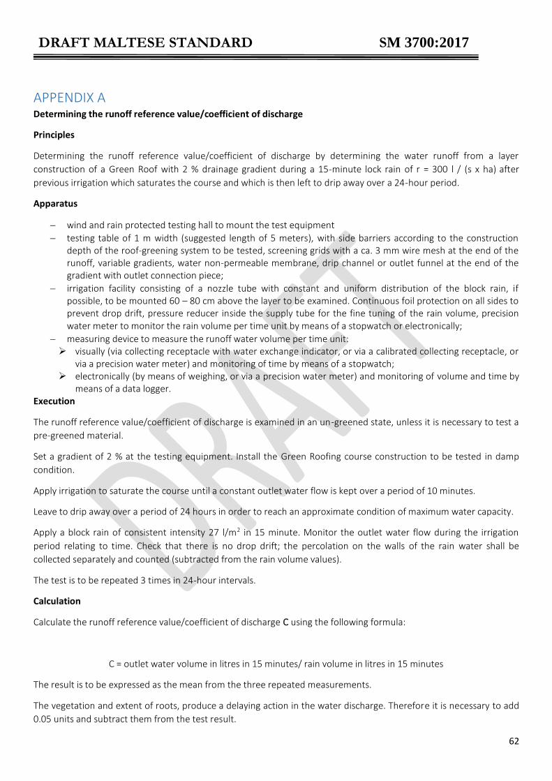
DRAFT MALTESE STANDARD SM 3700:2017
62
APPENDIX A Determining the runoff reference value/coefficient of discharge
Principles
Determining the runoff reference value/coefficient of discharge by determining the water runoff from a layer
construction of a Green Roof with 2 % drainage gradient during a 15-minute lock rain of r = 300 l / (s x ha) after
previous irrigation which saturates the course and which is then left to drip away over a 24-hour period.
Apparatus
wind and rain protected testing hall to mount the test equipment
testing table of 1 m width (suggested length of 5 meters), with side barriers according to the construction depth of the roof-greening system to be tested, screening grids with a ca. 3 mm wire mesh at the end of the runoff, variable gradients, water non-permeable membrane, drip channel or outlet funnel at the end of the gradient with outlet connection piece;
irrigation facility consisting of a nozzle tube with constant and uniform distribution of the block rain, if possible, to be mounted 60 – 80 cm above the layer to be examined. Continuous foil protection on all sides to prevent drop drift, pressure reducer inside the supply tube for the fine tuning of the rain volume, precision water meter to monitor the rain volume per time unit by means of a stopwatch or electronically;
measuring device to measure the runoff water volume per time unit: visually (via collecting receptacle with water exchange indicator, or via a calibrated collecting receptacle, or
via a precision water meter) and monitoring of time by means of a stopwatch; electronically (by means of weighing, or via a precision water meter) and monitoring of volume and time by
means of a data logger. Execution
The runoff reference value/coefficient of discharge is examined in an un-greened state, unless it is necessary to test a
pre-greened material.
Set a gradient of 2 % at the testing equipment. Install the Green Roofing course construction to be tested in damp
condition.
Apply irrigation to saturate the course until a constant outlet water flow is kept over a period of 10 minutes.
Leave to drip away over a period of 24 hours in order to reach an approximate condition of maximum water capacity.
Apply a block rain of consistent intensity 27 l/m2 in 15 minute. Monitor the outlet water flow during the irrigation
period relating to time. Check that there is no drop drift; the percolation on the walls of the rain water shall be
collected separately and counted (subtracted from the rain volume values).
The test is to be repeated 3 times in 24-hour intervals.
Calculation
Calculate the runoff reference value/coefficient of discharge C using the following formula:
C = outlet water volume in litres in 15 minutes/ rain volume in litres in 15 minutes
The result is to be expressed as the mean from the three repeated measurements.
The vegetation and extent of roots, produce a delaying action in the water discharge. Therefore it is necessary to add
0.05 units and subtract them from the test result.

DRAFT MALTESE STANDARD SM 3700:2017
63
APPENDIX B
Determination of compressibility and permeability
Apparatus
- cylindrical plastic containers with an inside diameter of 150 mm and a height of 165 mm, with a base perforated
diameter 5 mm (see example below):
Radius interval: 15°
Perforation perimeter spacing: 10 mm
Perforation diameter: 5 mm
Number of perforation:
Centre: 1 x 1 = 1
90° intervals: 4 x 7 = 28
30°/60° intervals: 8 x 6 = 48
15°/45°75° intervals: 12 x 4 = 48
- screening: 0.6 mm mesh wire, diameter 148 mm
- 7 mm steel plate, diameter 148 mm (proctor compaction test as per DIN 18127)
- proctor hammer, 4.5 kg drop weight, 450 mm drop height (proctor compaction test as per DIN 18127)
- plastic dry dishes heat-resistant to 150° C, with a diameter of app. 30 cm
- drying cabinet
- scales, accurate to within 0.1 g
- plastic bowls with a depth of at least 200 mm for immersion
- spacers, roughly 10 mm deep, to allow water access through a perforated base
- 148 mm diameter filter fleece to cover the top of the sample
- 0.6 mm gauge 148 mm diameter wire mesh to cover the top of the sample
- 100 x 100 mm stone as a weight to rest on top of the sample
- plastic bowls to allow the water to drip away, with drainage channels on top of them, made from spherical pieces of
bonded foam and measuring at least 50 mm in depth.
- test prods: wire ring, diameter approximately 40 mm, with tow test prods attached vertically
to it, these being 45 mm and 35 mm in length.
Compaction of the sample
Estimate visually/manually how cool/moist the test material is (it must not be wet), set thewater content visually, then
test water content. Where water is added, the sample must be left for at least 3 hours under air-tight conditions
before any further work is done with it, in order to ensure even moisture levels throughout the sample.

DRAFT MALTESE STANDARD SM 3700:2017
64
Fill the cylindrical container to a depth of between 120 mm and 140 mm with a quantity of the material under
examination, which must be cool / moist; find the depth of the sample in its fresh state by making four cross
measurements from the upper rim of the cylinder to the surface of the sample and then subtracting the result from
the internal height the cylinder (depth1). The container is filled to a level which will ultimately leave a depth of 100
mm or thereabouts after compaction. Place the steel plate over the top of the material with which the container is
filled and then strike 6 times with the Proctor hammer to compact it. Find the depth of the sample in its compacted
state by making four cross measurements from the upper rim of the cylinder to the surface of the sample and then
subtracting the result from the internal height the cylinder (depth2).
Calculation
Compressibility (%) = 100 x [(depth1 – depth2) / depth1]
Permeability test
The water permeability is calculated as the water infiltration rate / coefficient of absorption (Kf mod.). Coefficient of
absorption (Kf mod.) for the materials in compacted condition inside cylindrical vessels at maximum water capacity is
found by measuring the fall over a given period in the level of the water in which the materials are totally immersed.
Saturation of the sample.
Compacted materials inside cylindrical vessels shall be saturated through total immersion for 24 hours in water and
then left to drip away over a 2-hour period, as described below;
o place the fabric filter and wire mesh on top of the materials inside the cylindrical and then weight these down with stones to prevent the contents from rising;
o place the vessels in plastic bowls and fill slowly with water until the level reaches approximately 10 mm below the top of the test sample;
o dampen the surface of the test sample thoroughly and then add more water until the level is 10 mm above the top of the test sample (add more water, if necessary, in order to maintain that level);
o after the test sample has been totally immersed for 24 hours, remove the vessels and place them on top of the draining boards positioned over the plastic basins for 2 hours
Cover the surface of the test saturated sample with wire mesh, place the test prod on top and then fill the cylinder
carefully with water from the top until the surface of the water is between 10 and 20 mm above the top of the test
sample. Add water continuously as the water level drops, in such a manner as to maintain the total immersion depth.
Measurement actually commences as soon as water begins to flow evenly out of the perforated base. Fill with water
until the surface is above the tip of the upper test prod. Observe the water as the level drops and note the time taken
for it to drop from tip of the upper test prod to that of the lower one, in other words, from 45 mm to 35 mm. The
measurement is to be repeated at least for 3 times.
Calculation
Permeability expressed as mm/min = mod Kf (cm/sec) x 600
mod. Kf (cm/sec) = [1/t] x [/(h+4)]
h = the depth of the commpacted test material in the cylindrical vessel (cm)
t = the time taken for the water level to drop from 45 mm to 35 mm (second)

DRAFT MALTESE STANDARD SM 3700:2017
65
APPENDIX C
Calculation Calculate water permeability (mod. Kf) using the following formula:
h = the depth in cm of the compacted test material (see 2.3) t = the time in s taken for the water level to drop from 45 mm to 35 mm The result is to be expressed as the mean for all measurements.