draft environmental impact assessment...
TRANSCRIPT

Draft Environmental Impact Assessment
Report
Project proponent
For
Coal Based Power Plant
(2 * 135 MW)
3rd Floor, K. G. Chambers, Opp. Gujarat Samachar Press, Udhna Darwaja, Ring Road,
Surat - 395 002.
Narmada Thermal Power Limited At
Survey no.134,135A,135B,137,138,
Village: Padaria, Taluka: Vagra,
District: Bharuch, Gujarat
Prepared By:

Report Details
Draft EIA report
Owner:
Narmada Thermal Power Limite
Work Contractor:
Project Name: ENVIRONMEN
F
Copy Holder: NARMADA THERM
Document title: DRAFT ENVIRO
NAR
Total Pages: 312
Document no.: DT/NTPL /EIA/1
© Detox Corporation Pvt. Ltd., J
All rights Reserved. This Publication
condition that this work may not b
the written consent of Detox Corpor
Date
Originator
Project
Engineer
2011 Ankita
Bhairaviya
Pushpak
Shah
ed
NTAL IMPACT ASSESSMENT STUDY REP
FOR COAL BASED POWER PLANT
AL POWER LIMITED
ONMENTAL IMPACT ASSESSMENT REPO
FOR
RMADA THERMAL POWER LIMITED
10-11/28
une 2011
n is the property of Detox Corporation Pvt.
e reproduced or used (entirely or partially
ration Pvt. Ltd.
Reviewer
Project
Director
Pushpak
Shah
Chetan
Contractor
PORT
ORT
Ltd. and is released on the
y) for any purpose with out

Draft EIA report for Narmada Thermal Power Limited i
Index Sr. no Content Page no
CHAPTER 1
1.0 COMPANY PROFILE 1-1
1.1 PROPOSED PROJECT 1-1
1.2 JUSTIFICATION OF PROJECT 1-1
1.3 CAPITAL COST OF PROJECT 1-2
1.4 SITE SELECTION CRITERIA 1-2
1.5 SALIENT FEATURES OF SITE 1-2
1.6 LAND AREA BREAK UP 1-7
1.7 PURPOSE OF THE STUDY 1-7
1.8 DEFINITION OF EIA 1-7
1.9 METHODOLOGY 1-8
1.10 SCOPE OF ENVIRONMENT IMPACT ASSESSMENT (EIA) 1-8
1.11 ENVIRONMENTAL LEGISLATION APPLICABLE TO THE POWER PLANT
PROJECT
1-10
1.12 STRUCTURE OF THE REPORT 1-14
CHAPTER 2
2.1 PROPOSED PROJECT 2-1
2.2 FUEL/ RAW MATERIAL DETAILS 2-1
2.3 FUEL HANDLING SYSTEM 2-2
2.3.1 Coal Preparation and Firing System 2-2
2.3.2 Fuel Handling System 2-2
2.3.2.1 Coal 2-2
2.3.2.2 Diesel Oil: 2-4
2.4 FUEL ANALYSIS 2-4
2.5 PROCESS DESCRIPTION 2-6
2.6 MAJOR MECHANICAL EQUIPMENTS & AUXILIARIES/ UTILITY 2-7
2.6.1 Steam Generator 2-7
2.6.2 Auxiliary Steam System 2-8
2.6.3 Turbine and its auxiliarie 2-8
2.6.4 Air Cooled Condenser 2-9
2.6.5 Auxiliary Cooling System 2-10
Draft EIA report for Narmada Thermal Power Limited ii
2.6.6 Furnace 2-10
2.6.7 Air and flue gas system 2-10
2.6.8 Fuel Oil Burning System 2-11
2.6.9 Soot Blowing System 2-12
2.6.10 Air Extraction System 2-12
2.6.11 Lube Oil System 2-12
2.6.12 HP / LP Bypass 2-13
2.6.13 Boiler Feed Pumps 2-13
2.6.14 Condensate Pumps 2-14
2.6.15 Electric Power Supply System 2-14
2.7 POWER EVACUATION 2-14
2.8 ENVIRONMENT PARAMETERS 2-15
2.8.1 WATER 2-15
2.8.2 Air Pollution Control Equipments 2-15
2.8.2.1 Electrostatic precipitators 2-15
2.8.2.2 Bag filters 2-17
2.8.2.3 Provision of future Installation of flue gas de sulphurising system (FGD) 2-17
2.8.3 Solid Waste 2-17
2.9
2.9.1
UTILITIES
RAW WATER TREATMENT PLANT:
2-18
2-18
2.9.1.1 Raw Water Chlorination System 2-18
2.9.1.2 Service Water System 2-19
2.9.1.3 Potable Water System 2-19
2.9.1.4 Closed Cooling Water System 2-19
2.9.2 Effluent Treatment Plan 2-20
2.9.3 D G SET 2-20
CHAPTER 3
3.1 AIR ENVIRONMENT 3-1
3.1.1 Design Network for Ambient Air Quality Monitoring Stations 3-1
3.1.2 Meteorology Station 3-1
3.1.3 One season AAQ data 3-3
3.1.3.1 Air monitoring Station 3-4
3.1.3.2 Method of Analysis 3-5
3.1.3.3 Baseline Data 3-6

Draft EIA report for Narmada Thermal Power Limited iii
3.2 WATER ENVIRONMENT 3-9
3.2.1 Water Sampling Location 3-9
3.2.2 Analysis Method 3-11
3.2.3 Ground water Quality 3-13
3.2.4 Surface water quality 3-14
3.3 NOISE ENVIRONMENT 3-15
3.4 LAND ENVIRONMENT 3-16
3.4.1 Study Area 3-16
3.4.2 Objective 3-18
3.4.3 Satellite Data Details 3-18
3.4.4 Methodology 3-18
3.5 SOIL ENVIRONMENT 3-21
3.6 BIODIVERSITY OF TERRESTRIAL ENVIRONMENT 3-23
3.6.1 Period of the study and Study area 3-23
3.6.2 Methodology 3-24
3.6.3 Terrestrial Floral and Faunal Components of the Study Area 3-24
3.6.4 Habitats 3-25
3.6.5 Floral Diversity of the Study Area 3-26
3.6.5.1 Trees 3-27
3.6.5.2 Shrubs 3-28
3.6.5.3 Herbs 3-29
3.6.5.4 Climbers and Twiners 3-30
3.6.6 Cultivated Plants in the Study Area 3-31
3.6.7 Horticultural Practices and Fruits Grown 3-31
3.6.8 Rare and Endangered Flora in the Study Area 3-32
3.6.9 Endemic Plants of the Study Area 3-32
3.6.10 Status of the Forest, Their Category in the Study Area 3-32
3.6.11. Faunal Biodiversity of the Study Area 3-33
3.6.11.1 Birds of the Study Area 3-33
3.6.11.2 Butterflies from the study area 3-35
3.6.11.3 Herpetofauna 3-36
3.6.11.4 Mammals 3-36
3.6.12 Rare and Endangered Fauna of the Study Area 3-37
3.6.13 Endemic Fauna of the Study Area 3-37

Draft EIA report for Narmada Thermal Power Limited iv
3.7 SOCIO ECONOMIC ENVIRONMENT 3-37
4.0 IMPACT IDENTIFICATION 4-1
CHAPTER 4
4.1 AIR ENVIRONMENT 4-2
4.1.1 Construction Phase 4-2
4.1.2 Operation Phase 4-3
4.2 AIR POLLUTION SOURCE 4-3
4.2.1 Sources of Fugitive emission: 4-3
4.2.2 Point source emission 4-5
4.3 DETAILS OF AIR DISPERSION MODEL 4-6
4. 4 WATER ENVIRONMENT 4-11
4.4.1 Source of water: 4-11
4.4.2 Water Consumption 4-11
4.4.3 Waste Water Generation 4-14
4.4.4
4.5
Treatability Study
LAND/ SOIL ENVIRONMENT
4-15
4-17
4.5.1 Construction Phase: 4-17
4.5.2 OPERATION PHASE 4-17
4.6 SOLID AND HAZARDOUS WASTE GENERATION 4-18
4.6.1 CONSTRUCTION PHASE 4-18
4.6.2 Operation phase 4-18
4.7 NOISE POLLUTION 4-19
4.7.1 Equipment noise 4-19
4.7.2 Far Field Noise 4-20
4.8 ECOLOGY [FLORA – FAUNA] 4-20
4.8.1 Construction Phase 4-20
4.8.2 Operation Phase 4-20
4.8.3 Impact Assessment on Biodiversity 4-21
4.9 SOCIOLOGICAL AND CULTURAL IMPACTS 4-21
CHAPTER 5
5.0 INTRODUCTION 5-1
5.1 CONSTRUCTION PHASE 5-1
5.2 OPERATION PHASE 5-3
Draft EIA report for Narmada Thermal Power Limited v
5.3 AIR ENVIRONMENT 5-3
5.3.1 Control of Fugitive Emissions 5-4
5.3.1.1 Coal handling 5-4
5.3.1.2 Fly ash handling 5-5
5.4 WATER ENVIRONMENT 5-6
5.4.1 Water Conservation steps 5-6
5.4.2 Rain Water Harvesting 5-6
5.4.3 WASTE WATER GENERATED 5-6
5.5 SOLID/ HAZARD WASTE GENERATION 5-7
5.5.15.
5.1.2.1
Ash handling system
Disposal of Ash
5-7
5-9
5.5.1.3 Ash Disposal Area 5-10
5.6 CLEANER PRODUCTION 5-10
5.7 ENVIRONMENT MANAGEMENT PLAN FOR LAND/ SOIL ENVIRONMENT 5-12
5.8 NOISE ENVIRONMENT 5-12
5.9 GREEN BELT DEVELOPMENT 5-13
5.9.1 Recommended Plants for Green Belt Development 5-13
5.9.2 Guidelines for plantation 5-13
5.9.3 Selection of plants for Greenbelts: 5-13
5.9.4 Roadside Plantation 5-17
5.10 ENVIRONMENT MANAGEMENT SYSTEM 5-19
5.11 BUDGETARY ALLOCATION FOR ENVIRONMENT MANAGEMENT PLAN 5-21
CHAPTER 6
6.0 POLLUTION MONITORING AND SURVEILLANCE SYSTEM 6-1
6.1 AMBIENT AIR QUALITY MONITORING 6-1
6.2 STACK MONITORING: 6-2
6.3 NOISE ENVIRONMENT 6-2
6.4 WATER AND WASTE WATER QUALITY MONITORING 6-2
6.4.1 Environment laboratory 6-2
CHAPTER 7
7.1 SOCIO ECONOMIC ACTIVITIES 7-1
7.2 EMPLOYMENT POTENTIAL: 7-2
7.3 BUDGETARY ALLOCATION 7-2
CHAPTER 8
Draft EIA report for Narmada Thermal Power Limited vi
8.1 INTRODUCTION 8-1
8.2 OBJECTIVES OF THE RISK ASSESSMENT 8-1
8.3 THE RISK ASSESSMENT PROCESS 8-1
8.4 IDENTIFICATION OF HAZARDS 8-4
8.4.1 Fire And Explosion Index & Toxicity Index 8-4
8.4.1.1 Hazardous Material Identification Methodology 8-4
8.4.1.2 F&EI Computation 8-5
8.4.1.4 Hazards Ranking 8-11
8.4.2 Consequence Analysis 8-12
8.5 RISK ANALYSIS DUE TO STORAGE AND HANDLING OF COAL 8-16
8.5.1 Hazard Identification 8-16
8.5.2 Risk Evaluation and Control Measures 8-18
8.6 RISK ANALYSIS DUE TO STORAGE AND HANDLING OF CHLORINE 8-24
8.6.1 Health hazards data 8-24
8.6.2 Environmental protection procedures 8-24
8.6.3 Special protection information 8-24
8.6.4 Transportation 8-25
8.7 RISK ANALYSIS DUE TO HSD AND LDO 8-26
8.7.1 Fire & Explosion Hazard: 8-26
8.7.2 Health hazard data 8-26
8.7.3 Preventive measures 8-26
8.7.4 Emergency and first aid measures 8-27
8.8 RISK ANALYSIS FOR ASH HANDLING SYSTEM 8-27
8.8.1 Various ash discharge point in a FBC boiler 8-27
8.9 OCCUPATIONAL HEALTH AND SAFETY 8-27
8.10 OTHER HAZARDS AND ITS CONTROLS 8-31
8.11 AUTOMATIC FIRE DETECTION AND CONTROL MEASURES 8-32
8.11.1 Fire water / hydrant system 8-32
8.11.2 Fire Alarm And Detection System 8-35
8.12 SAFETY ORGANIZATION AND ITS ACTIVITIES 8-36
8.12.1 Construction and Erection Phase 8-36
8.12.2 Operation and Maintenance Phase 8-36
8.12.3 Strengthening of HSE and Meeting by Safety and quality circle 8-36
8.12.4 Safety Training 8-36

Draft EIA report for Narmada Thermal Power Limited vii
8.13 HEALTH AND SAFETY MONITORING PLAN 8-37
8.13.1 Do’s and Don’ts checklis 8-37
CHAPTER 9
9.1 GENERAL 9-1
9.2 PURPOSE AND SCOPE OF DMP 9-1
9.3 CAUSES OF DISASTER 9-2
9.4 DISASTER CONTROL PHILOSOPHY 9-2
9.5 DISASTER CONTROL PLAN 9-2
9.6 FIRE FIGHTING ARRANGEMENT 9-4
9.7 SAFETY AND PERSONAL PROTECTIVE APPLIANCES 9-5
9.8 EMERGENCY ACTION PLAN 9-5
9.8.1 FIRST INFORMATION 9-6
9.8.2 Responsibilities of Work Incident Controller (WIC) 9-6
9.8.3 Responsibilities of Chief Incident Controller (CIC) 9-6
9.8.4 Responsibilities For Declaration Of Major Emergency 9-6
9.8.5 Responsibilities of Emergency Communication Officer (ECO) 9-7
9.8.6 Key Personnel 9-7
9.8.7 Responsibilities of Key Personnel 9-8
9.9 EMERGENCY CONTROL CENTRE 9-9
9.10 Off-Site Emergency Preparedness Plan 9-11
9.10.1 Aspects proposed to be considered in the Off-Site Emergency Plan 9-13
9.10.2 Role of the Emergency Co-ordinating Officer 9-14
9.10.3 Role of the Local Authority 9-14
9.10.4 Role of Police 9-14
9.10.5 Role of Fire Authorities 9-14
9.10.6 Role of Health Authorities 9-14
9.10.7 Role of Government Safety Authority 9-15
9.11 SAFETY & EMERGENCY PLAN 9-17
9.12 PRE-EMERGENCY ACTIONS 9-18
9.13 TRANSPORT AND COMMUNICATION 9-18
CHAPTER 10
10.1 LAND AVAILABILITY AND REQUIREMENT 10-1
10.2 FUEL REQUIREMENT, STORAGE & HANDLING SYSTEM 10-1

Draft EIA report for Narmada Thermal Power Limited viii
10.3 WATER AVAILABILITY AND REQUIREMENT 10-1
10.4 ENVIRONMENT IMPACT ASSESSMENT STUDY 10-1
10.5 ANTICIPATED ENVIRONMENTAL IMPACTS AND MITIGATION MEASURES 10-2
10.5.1 Land Use: 10-2
10.5.2 Water Use and Hydrology: 10-2
10.5.3 Demography and Socio-economics: 10-2
10.5.4 Air Quality 10-2
10.5.5 Water Quality 10-2
10.5.6 Noise 10-2
10.6 DISASTER MANAGEMENT PLAN 10-3
10.7 PROJECT BENEFITS 10-3
10.8 ENVIRONMENT MANAGEMENT PLAN 10-3
10.9 ENVIRONMENT MONITORING PLAN 10-4
CHAPTER 11
11.1 GENERAL INFORMATION 11-1
11.2 VISION AND BUSINESS ETHICS 11-1
11.3 KEY FACTS 11-1
11.4 ACCREDITATIONS & REGISTRATIONS 11-1
11.5 ACTIVITES 11-1
11.6 EIA TEAM 11-3

Draft EIA report for Narmada Thermal Power Limited ix
List of tables Table no. Content Page no.
1.1 Product Profile 1-1
1.2 Salient Features of site 1-3
1.3 Land area break up 1-7
1.4 Ambient Noise Quality Standards in respect of public places 1-12
1.5 Ambient air Quality standard 1-13
2.1 Power generation break up 2-1
2.2 Raw material details 2-1
2.3 Analysis of coal 2-4
2.4 Analysis of HSD 2-5
2.5 Analysis of light diesel oil 2-5
2.6 Technical details of ESP 2-16
2.7 Bag filter details 2-17
3.1 Air monitoring location 5
3.2 Analysis methods and Instrument details 5
3.3 Analysis methods and Instrument details 6
3.4 Ground Water monitoring location 9
3.5 Surface Water monitoring location 9
3.6 Method of Analysis 11
3.7 Ground water quality 13
3.8 Surface water quality 14
3.9 Noise monitoring locations 15
3.10 Day and Night Noise Levels 16

Draft EIA report for Narmada Thermal Power Limited x
3.11 LULC classification system 19
3.12 Land use/Land covers Statistics within 10 Km. Radius from Project Site 20
3.13 Soil Sampling Locations 21
3.14 Physical Characteristics of Soil in the Study Area 22
3.15 Soil quality 23
3.16 List of Villages covered under the present baseline study 24
3.17 Trees in the study area 26
3.18 Lists of Shrubs in the Study Area 28
3.19 List of herbaceous species observed in the area 29
3.20 List of Climbers Observed in the Study Area 30
3.21 Near Threatened Birds of the Study Area 33
3.22 Systematic Lists of Birds in the Study Area with Its Distribution And Migratory Status
33
3.23 Butterflies in the study area 35
3.24 Reptiles in the Study Area 36
3.25 Mammals in Core Zone 36
3.26 Mammals in the Buffer Zone 36
3.27 Summary of Demographic structure 38
3.28 Demography of the study area 41
4.1 No. of dumpers/ trucks used for transportation 4-4
4.2 Details of Main Stacks 4-5
4.3 Details of fugitive emission stacks 4-6
4.4 Resultant Concentrations Due To Incremental GLC* 4-10
4.5 Raw water characteristics 4-11
4.6 Water consumption 4-11
4.7 Waste water generation 4-14

Draft EIA report for Narmada Thermal Power Limited xi
4.8 Qualitative Analysis 4-15
4.9 Details of Hazardous Wastes generation and Disposal 4-18
4.10 Solid waste generation 4-19
5.1 Action plan for implementation of CP 5-11
5.2 Recommended Plant Species for Green Belt Development 5-15
5.3 Three Tire plantation management 5-17
5.4 Budgetary allocation 5-17
5.5 Species Selected for Plantation along the roadside of plant and
Township
5-18
5.6 Estimated Cost for Environmental Management Plan 5-21
6.1 Sampling and analytical Instruments required 6-3
6.2 Monitoring schedule 6-4
7.1 Employment details 7-2
8.1 Fire and explosion index for coal 8-5
8.2 Fire and explosion index for HSD storage 8-7
8.3 Fire and explosion index for chlorine 8-9
8.4 Conclusion 8-11
8.5 Illumination level 8-23
8.6 Other Hazards and Its Controls 8-32
8.7 Type of detectors 8-35
9.1 List of Proposed Safety Equipment 9-5
10.1 Raw material details 10-1
11.1 EIA team members 11-3

Draft EIA report for Narmada Thermal Power Limited xii
List of Figures Figure no. Figure Page no.
1.1 Google image showing the project site and surrounding
villages
1-5
1.2 Village map of 10 Km radius surrounding the project site 1-6
3.1 Wind rose for summer season 3-3
3.2 Air sampling location 3-4
3.3 Measured ambient PM10 concentration 3-7
3.4 Measured ambient PM2.5 concentration 3-7
3.5 Measured ambient NOx concentration 3-8
3.6 Measured ambient SO2 concentration 3-8
3.7 Ground water monitoring locations 3-10
3.8 Surface water monitoring locations 3-11
3.9 Land use map of the study area 3-17
3.10 Land use area distribution 3-21
3.11 Soil sampling location 3-22
4.1 Isopleths of PM 4-7
4.2 Isopleths of SO2 4-8
4.3 Isopleths of NOx 4-9
4.4 Water balance diagram 4-13
5.1 Environment management cell 5-20
9.1 Onsite emergency plan 9-11
9.2 Off site emergency plan 9-16

Draft EIA report for Narmada Thermal Power Limited xiii
List of Annexure Annexure 1 : Lay out map
Annexure 2 : Letter from DoEF regarding CRZ applicability
Annexure 3 : Fuel allocation letter
Annexure 4 : Water allocation letter
Annexure 5 : TSDF membership certificate
Annexure 6 : MoU with brick manufacturers
Annexure 7 : Meteorology data
Annexure 8 : Undertaking
Annexure 9 : TOR copy and its compliance
Draft EIA report for Narmada Thermal Power Limited 1-1
Chapter 1 Introduction
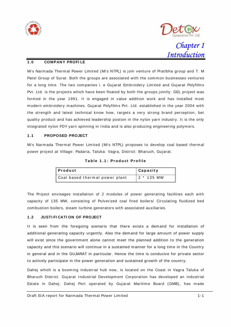
1.0 COMPANY PROFILE
M/s Narmada Thermal Power Limited (M/s NTPL) is join venture of Pratibha group and T. M
Patel Group of Surat. Both the groups are associated with the common businesses ventures
for a long time. The two companies i. e Gujarat Embroidery Limited and Gujarat Polyfilms
Pvt. Ltd. is the projects which have been floated by both the groups jointly. GEL project was
formed in the year 1991. It is engaged in value addition work and has installed most
modern embroidery machines. Gujarat Polyfilms Pvt. Ltd. established in the year 2004 with
the strength and latest technical know how, targets a very strong brand perception, bet
quality product and has achieved leadership postion in the nylon yarn industry. It is the only
integrated nylon FDY yarn spinning in India and is also producing engineering polymers.
1.1 PROPOSED PROJECT
M/s Narmada Thermal Power Limited (M/s NTPL) proposes to develop coal based thermal
power project at Village: Padaria, Taluka: Vagra, District: Bharuch, Gujarat.
Table 1.1: Product Profile
Product Capacity
Coal based thermal power plant 2 * 135 MW
The Project envisages installation of 2 modules of power generating facilities each with
capacity of 135 MW, consisting of Pulverized coal fired boilers/ Circulating fluidized bed
combustion boilers, steam turbine generators with associated auxiliaries.
1.2 JUSTIFICATION OF PROJECT
It is seen from the foregoing scenario that there exists a demand for installation of
additional generating capacity urgently. Also the demand for large amount of power supply
will exist since the government alone cannot meet the planned addition to the generation
capacity and this scenario will continue in a sustained manner for a long time in the Country
in general and in the GUJARAT in particular. Hence the time is conducive for private sector
to actively participate in the power generation and sustained growth of the country.
Dahej which is a booming industrial hub now, is located on the Coast in Vagra Taluka of
Bharuch District. Gujarat Industrial Development Corporation has developed an industrial
Estate in Dahej. Dahej Port operated by Gujarat Maritime Board (GMB), has made

Draft EIA report for Narmada Thermal Power Limited 1-2
significant contribution to facilitate industrial growth in the district. Also High connectivity to
port has lead to industrial development in the area.
Apart from the exiting industries many new industrial development are in line at GIDC
estate of Dahej and Special Economic Zone.
Due to the above proposed developments there shall be increase in the power requirement
in the area. In order to meet the increasing power demand, Narmada Thermal Power
Limited, has proposed to installed 2 * 135 MW coal based thermal power plant at proposed
location.
1.3 CAPITAL COST OF PROJECT
The total cost of project is Rs. 14850 millions (approximate).
1.4 SITE SELECTION CRITERIA
The following factors, which influence selection of site have been considered in the
identifying the prospective site:
Area away from ecologically sensitive, R&R prone, notified reserve forests etc.
Availability of adequate land for locating the coal fired power plant with a capacity of
2 X 135 MW with a proposal to expand in future. Suitability of the land from
topography and geological aspects.
Proximity to rail / road / seaport to facilitate transportation of equipment,
construction material indigenous coal as well as imported coal, and auxiliary fuel.
Availability of adequate quantity of Raw water to meet plant water requirements
Power evacuation facility: proximity to an existing EHV (220 kV) sub-station.
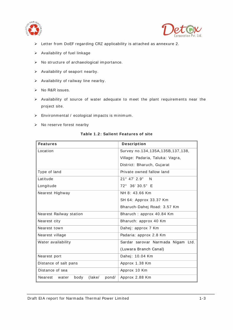
1.5 SALIENT FEATURES OF SITE
The salient features of the project are as mentioned below:
Adequate land is available for the power plant including transformer yard &
switchyard, balance of plant (BOP) facilities such as water storage facilities with
radiator coolers; switchyard and associated power evacuation facilities;
Availability of adequate land for other construction activities, roads, water treatment
plants, DG sets and green belt etc.,
Existing road connectivity to the plant site for movement of equipment, construction
materials, pipes, etc. This site is approachable through Bharuch-Dahej highway
Draft EIA report for Narmada Thermal Power Limited 1-3
Letter from DoEF regarding CRZ applicability is attached as annexure 2.
Availability of fuel linkage
No structure of archaeological importance.
Availability of seaport nearby.
Availability of railway line nearby.
No R&R issues.
Availability of source of water adequate to meet the plant requirements near the
project site.
Environmental / ecological impacts is minimum.
No reserve forest nearby
Table 1.2: Salient Features of site
Features Description
Location Survey no.134,135A,135B,137,138,
Village: Padaria, Taluka: Vagra,
District: Bharuch, Gujarat
Type of land Private owned fallow land
Latitude
Longitude
21° 47' 2.9" N
72° 36' 30.5" E
Nearest Highway NH 8: 43.66 Km
SH 64: Approx 33.37 Km
Bharuch-Dahej Road: 3.57 Km
Nearest Railway station Bharuch : approx 40.84 Km
Nearest city Bharuch: approx 40 Km
Nearest town Dahej: approx 7 Km
Nearest village Padaria: approx 2.8 Km
Water availability Sardar sarovar Narmada Nigam Ltd.
(Luwara Branch Canal)
Nearest port Dahej: 10.04 Km
Distance of salt pans Approx 1.38 Km
Distance of sea Approx 10 Km
Nearest water body (lake/ pond/ Approx 2.88 Km

Draft EIA report for Narmada Thermal Power Limited 1-4
reservoir/ canal)
Distance of mangroves Approx 4.47 Km
National park/ sanctuary/ reserve forest None within 10 Km radius
Heritage site None within 10 Km radius
**Aerial distance is considered

Draft EIA report for Narmada Thermal Power Limited 1-5
The satellite image of the project site with the surrounding area is as shown in the figure below
Figure 1.1: Google image showing the project site and surrounding villages
Bharuch dahej road
Dahej - Jambusar road
Salt pan area Sea

Draft EIA report for Narmada Thermal Power Limited 1-6
The site map of the project site and surrounding villages in 10 km radius is as shown in the figure below:
Figure 1.2: Village map of 10 Km radius surrounding the project site

Draft EIA report for Narmada Thermal Power Limited 1-7
1.6 LAND AREA BREAK UP
The total land area available is 122 acres and the detail area bifurcation is as given in
the table below:
Table 1.3: Land area break up
Purpose Area provided
Power plant area 39 acres
Fuel storage 12 acres
Ash pond 20 acres
Green belt 42 acres
Open area 9 acres
Total 122 acres
Layout plan of the proposed project with provision of unobstructed peripheral area and
showing separate entry and exit gates is attached as annexure 1.
1.7 PURPOSE OF THE STUDY
The proposed project i.e. Thermal Power Plants (270 MW) fall under category B Sr. no. 1
(d) in the Government of India Notification no. 1533 dated 14th September, 2006; which
require prior Environmental Clearance before starting construction, production or any
other allied activities related to the project. For getting the Environmental Clearance; it
is required to carry out the Environmental Impact Assessment (EIA) study report.
In order to assess the environmental impacts arising out of the proposed project
activities, M/s NTPL retained M/s Detox Corporation Private Limited as EIA consultants to
undertake Rapid Environmental Impact Assessment for various environmental
components which may be affected and to delineate a detailed Environmental
Management Plan (EMP).
1.8 DEFINITION OF EIA
Environmental Impact Assessment (EIA) is a formal process used to predict how
industrial development or construction project will affect natural resources such as
water, air, land, socioeconomic and bio ecological environment.
An EIA usually involves a sequence of steps:
(1) Screening to decide if a project requires assessment and to what level of detail.
(2) Preliminary assessment to identify key impacts, their magnitude, significance, and
importance.

Draft EIA report for Narmada Thermal Power Limited 1-8
(3) Scoping to ensure the EIA focuses on key issues and to determine, where more
detailed information is needed.
(4) Implementing the main EIA study, which involves detailed investigations to predict
impacts, assess their consequences.
1.9 METHODOLOGY
Environmental Impact Assessment (EIA) studies include identification, assessment,
quantitative evaluation and prediction of possible impacts. To minimize the impact of the
project on various environmental attributes, mitigation measures are suggested for
implementation along with the project.
The methodology of this study can be schematized as detailed below:
To gather information on present environmental conditions and relevant national
environmental guidelines and EIA procedures.
Scoping of impacts.
Assessment of significant impacts.
Description of residual impacts.
Development of monitoring plans.
To inform all relevant and involved authorities regarding the impact of the project
on the environment and the proposed mitigation measures.
1.10 SCOPE OF ENVIRONMENT IMPACT ASSESSMENT (EIA)
This report represents the environmental impact assessment and management plan of
the proposed 2x 135 MW coal based power projects at Village: Padaria, Taluka: Vagra in
the Bharuch District of Gujarat State being developed by M/s Narmada Thermal Power
Limited.
As per the requirements stated in the Environmental Impact Assessment Notification 2006
and its subsequent amendments, Environmental Impact Assessment (EIA) study has been
undertaken to assess the environmental impacts of the proposed project and to develop a
site specific environmental management plan and risk mitigation measures. Subsequently,
baseline environmental studies have been conducted during the summer season (March
2011 to May 2011) and developed this Environmental Impact Assessment (EIA) report as
per the guidelines, Manuals and best practices suggested by Ministry of Environment and
Forests (MoEF). The project was placed before the Gujarat State Environment Appraisal
Committee for approval of TOR for the EIA study.

Draft EIA report for Narmada Thermal Power Limited 1-9
The EIA report has been prepared as per the TOR issued by State Level Expert Appraisal
Committee vide letter no EIA-10-2010-777-E/71863 dated 01/02/2011 and revised TOR
issued vide letter no. EIA-10-2010-777-E/79413 dated 06/05/2011. The compliance
report of TOR along with TOR copy is attached herewith as annexure 9.
The following tasks were undertaken as a part of the EIA study:
• A review of the detail project report was undertaken to comprehend the process
technology, facility layout, water demand and environmental and safety risk
mitigation measures considered at the conceptual design phase of the project.
The project information has been used for quantifying the residual
environmental impacts, if any, due to the operation of the facility.
• Secondary baseline data with regards to meteorology, hydrology, geology,
biodiversity, forests, socio-economic information etc. was collected from various
published data and from concerned Government departments. Land use pattern
was mapped within 10 Sq. Km area around the project site using satellite
imaginary.
• A rigorous baseline monitoring program was undertaken during summer season
to establish the background air quality, surface and groundwater quality, soil
quality and noise levels in the study area.
• Site specific meteorological data was collected from the automatic
meteorological station operated at the plant site. The information/data
generated was used for air quality modeling assessment.
• As the proposed thermal power plant utilizes Coal as base fuel, The primary
concern of the air quality management aspects are release of oxides of nitrogen,
Sulphur dioxide and particulate matters into the atmosphere. ISCST-3
(Industrial Source Complex Short term-3) model was used to predict the 24-
hours average concentrations of these parameters in the study area.
• The water balance for the plant has been thoroughly studied and wherever
possible, water conservation and wastewater recycling programs have been
explored. Wastewater streams have been identified and adequate treatment and
disposal schemes have been developed.
• Solid and hazardous waste management programs have been evolved.
• A survey of terrestrial flora and fauna in the study area was undertaken to
identify the existing base line conditions.
• A detailed review of the socio-economic status of the study area was carried out
to establish the positive and negative impacts on the socioeconomic
environment and biodiversity in the study area.

Draft EIA report for Narmada Thermal Power Limited 1-10
• Based on the detailed EIA study, various environmental risk mitigation measures
were identified and a detailed Environmental Management Plan (EMP) has been
developed.
1.11 ENVIRONMENTAL LEGISLATION APPLICABLE TO THE POWER PLANT
PROJECT
Clearance from Gujarat pollution control board:
According to section 21 of Air (Prevention& control of pollution) Act, 1981 and section 25
of water (Prevention & Control of pollution) act, 1974, no person shall establish or
operate any activity, which can cause air or water pollution without obtaining Consent to
Establish (CTE). As per the above mentioned Air and Water act, CTE has to be obtained
from Gujarat Pollution Control Board (GPCB) in the form of No Objection Certificate
(NOC) after the submission of Air/water consent forms with requisite fees. This NOC has
to be subsequently followed by Consolidated Consent & Authorization (CC&A) before
staring Production Activities.
Environment Clearance from Environment Impact Assessment Authority (EIAA)
As Per EIA Notification (S.O. 1533) Dated 14th September 2006 & Amended
Thereafter.
In exercise of the powers conferred by sub-section (1) and clause (v) of sub-section (2)
of section 3 of the Environment (Protection) Act, 1986, and clause (d) of sub-rule (3) of
rule 5 of the Environment (Protection) Rules, 1986 and in supersession of the notification
number S.O. 60 (E) dated the 27th January, 1994, the Central Government directed that
on and from the date of the publication (14th September 2009) of the EIA notification
(SO 1553), construction of new projects or activities or the expansion or modernization
of existing projects or activities listed in the Schedule shall be undertaken in any part of
India only after the prior environmental clearance from the Central Government or as
the case may be, by the State Level Environment Impact Assessment Authority, duly
constituted by the Central Government under sub-section (3) of section 3 of the said Act,
in accordance with the procedure specified hereinafter in this notification.
Other Environmental Legislation Applicable To the Project:
Any project activities will be governed by various acts and rules and regulation set by
Ministry of Environment and Forest (MoEF) at the central level and other regulatory
agencies at the state levels. Various environmental standards and guidelines of Central
Pollution Control Board and Gujarat state pollution Control Board will also be applicable.
The Water (Prevention & Control of Pollution) Act, 1974 as amended deals
comprehensively with water issues. It empowers the Government to constitute Pollution

Draft EIA report for Narmada Thermal Power Limited 1-11
Control Boards to maintain the wholesomeness of national water bodies. It enables
Central and State Pollution Control Boards to prescribe standards and has provisions for
monitoring & compliance and penal provisions against the violators of the Act. It
provides the permit system i.e. “Consent” procedure to prevent and control of water
pollution. The Act empowers State Boards to issue directions to the defaulters.
Environment (Protection) Act, 1986 has a broad coverage in which ‘Environment’
includes water, air and land and there exists an interrelationship among water, air, land,
human beings and other creatures. It empowers to take measures in protecting and
improving the quality of the environment through preventing, controlling and abating
environmental pollution. The Government is authorized to set national standards for
ambient environmental quality and controlling discharges to regulate industrial locations,
to prescribe procedure for hazardous substance management and to collect and
disseminate information regarding environmental pollution. The Act provides for severe
penalties for those who fail to comply with or contravenes any provision of the Act.
The Manufacture, Storage, Import of Hazardous Chemicals Rules, 1989 and its
amendments under EPA, 1986 has identified the responsibilities of various stakeholders
for management of chemicals and containment of spillage.
The Hazardous Wastes (Management and Handling) Rules, 1989 and its
subsequent Amendment 2000 were created to provide ‘cradle-to grave’ or
comprehensive guidance to the generators, transporters and operators of disposal
facilities among others, and monitoring norms for State governments.
As per the provisions of Hazardous Waste (Management & Handling) Rules, 1989, as
amended, every occupier handling, or recycler recycling, hazardous wastes including
facility for collection, reception, treatment, transport, storage and disposal of such
wastes is required to obtain authorization from concerned State Pollution Control Board
(SPCB)/Pollution Control Committee (PCC) in UT for any of the said activities.
MoEF notification S.O.470 (E) – 21st June, 1999 Environment (Siting for Industrial
Projects) Rules, 1999
MoEF Notification G.S.R. 37I (E) dated 17th May, 2002. In exercise of the powers
conferred by sections 6 and 25 of the Environment (Protection) Act, 1986 (29 of 1986),
the Central Government made the following rules further to amend the Environment
(Protection) Rules, 1986, regarding noise limit for generator sets run with diesel
The maximum permissible sound pressure level for new diesel generator (DG)sets with
rated capacity up to 1000 KVA, manufactured on or after the 1st July,2003 shall be 75
dB(A) at 1 meter from the enclosure surface.

Draft EIA report for Narmada Thermal Power Limited 1-12
The diesel generator sets should be provided with integral acoustic enclosure at the
manufacturing stage itself. The user shall make efforts to bring down the noise levels
due to the DG set, outside his premises, within the ambient noise requirements by
proper siting and control measures.
S.O. 123(E). - The Noise Pollution (Regulation and Control) Rules, 2000 dated
14 February, 2000
Due to the increasing ambient noise levels in public places from various sources;
industrial activity, construction activity, generator sets, loud speakers, public address
systems, music systems, vehicular horns and other mechanical devices have deleterious
effects on human health and the psychological well being of the people, it was
considered necessary to regulate and control noise producing and generating sources
with the objective of maintaining the ambient air quality standards. In this respect
following noise quality standard was suggested.
Table 1.4: Ambient Noise Quality Standards in respect of public places
Area
Code
Category of
Area/Zone
Limits in dB(A) Leq *
Day time Night time
(A) Industrial area 75 70
(B) Commercial area 65 55
(C) Residential area 55 45
(D) Silence zone 50 40
Day time shall mean from 6.00 a.m. to 10.00 p.m. Night time shall mean from 10.00
p.m. to 6.00 a.m.
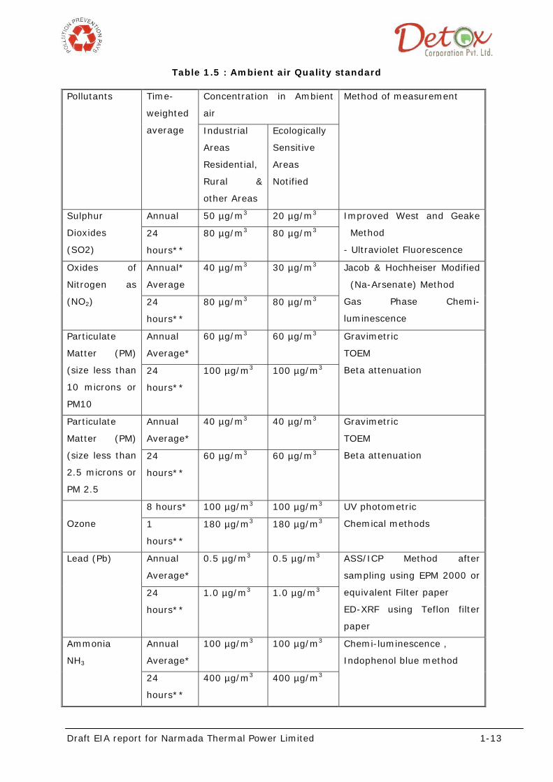
CPCB NATIONAL AMBIENT AIR QUALITY STANDARDS
MoEF amended National Ambient Air Quality Standards by the notification G.S.R. 826(E)
dated 16th November 2009,in exercise of the power conferred by section 6 and section
25 of Environment (protection ) act 1986, amended Environment ( Protection) rule 1986
as Environment ( Protection) seventh Amendment rules 2009.
Draft EIA report for Narmada Thermal Power Limited 1-13
Table 1.5 : Ambient air Quality standard
Pollutants Time-
weighted
average
Concentration in Ambient
air
Method of measurement
Industrial
Areas
Residential,
Rural &
other Areas
Ecologically
Sensitive
Areas
Notified
Sulphur
Dioxides
(SO2)
Annual 50 µg/m3 20 µg/m3 Improved West and Geake
Method
- Ultraviolet Fluorescence
24
hours**
80 µg/m3 80 µg/m3
Oxides of
Nitrogen as
(NO2)
Annual*
Average
40 µg/m3 30 µg/m3 Jacob & Hochheiser Modified
(Na-Arsenate) Method
Gas Phase Chemi-
luminescence
24
hours**
80 µg/m3 80 µg/m3
Particulate
Matter (PM)
(size less than
10 microns or
PM10
Annual
Average*
60 µg/m3 60 µg/m3 Gravimetric
TOEM
Beta attenuation 24
hours**
100 µg/m3 100 µg/m3
Particulate
Matter (PM)
(size less than
2.5 microns or
PM 2.5
Annual
Average*
40 µg/m3 40 µg/m3 Gravimetric
TOEM
Beta attenuation 24
hours**
60 µg/m3 60 µg/m3
Ozone
8 hours* 100 µg/m3 100 µg/m3 UV photometric
Chemical methods 1
hours**
180 µg/m3 180 µg/m3
Lead (Pb) Annual
Average*
0.5 µg/m3 0.5 µg/m3 ASS/ICP Method after
sampling using EPM 2000 or
equivalent Filter paper
ED-XRF using Teflon filter
paper
24
hours**
1.0 µg/m3 1.0 µg/m3
Ammonia
NH3
Annual
Average*
100 µg/m3 100 µg/m3 Chemi-luminescence ,
Indophenol blue method
24
hours**
400 µg/m3 400 µg/m3
Draft EIA report for Narmada Thermal Power Limited 1-14
Carbon
Monoxide
(CO)
8
hours**
0.2 mg/m3 0.2 mg/m3 Spectroscopy
Non dispersive infra red
(NDIR) 1 hour 0.4 mg/m3 0.4 mg/m3
* Annual Arithmetic mean of minimum 104 measurements in a year
taken twice a week 24 hourly at uniform interval.
** 24 hourly/8 hourly values should be met 98% of the time in a year.
However, 2% of the time, it may exceed but not on two consecutive
days.
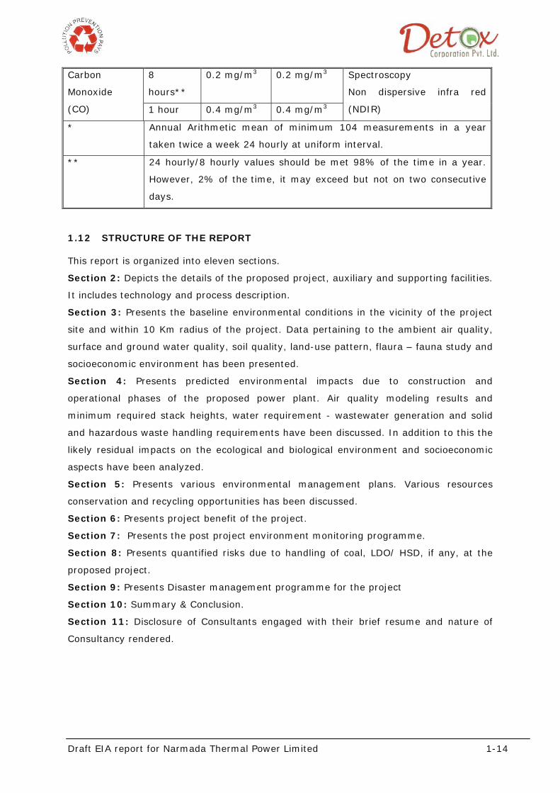
1.12 STRUCTURE OF THE REPORT
This report is organized into eleven sections.
Section 2: Depicts the details of the proposed project, auxiliary and supporting facilities.
It includes technology and process description.
Section 3: Presents the baseline environmental conditions in the vicinity of the project
site and within 10 Km radius of the project. Data pertaining to the ambient air quality,
surface and ground water quality, soil quality, land-use pattern, flaura – fauna study and
socioeconomic environment has been presented.
Section 4: Presents predicted environmental impacts due to construction and
operational phases of the proposed power plant. Air quality modeling results and
minimum required stack heights, water requirement - wastewater generation and solid
and hazardous waste handling requirements have been discussed. In addition to this the
likely residual impacts on the ecological and biological environment and socioeconomic
aspects have been analyzed.
Section 5: Presents various environmental management plans. Various resources
conservation and recycling opportunities has been discussed.
Section 6: Presents project benefit of the project.
Section 7: Presents the post project environment monitoring programme.
Section 8: Presents quantified risks due to handling of coal, LDO/ HSD, if any, at the
proposed project.
Section 9: Presents Disaster management programme for the project
Section 10: Summary & Conclusion.
Section 11: Disclosure of Consultants engaged with their brief resume and nature of
Consultancy rendered.

Draft EIA report for Narmada Thermal Power Limited 2- 1
Chapter-2 Project Description
The design, manufacture, inspection, testing and installation of all equipment and
systems of the proposed project shall confirm to the latest applicable editions of Indian
codes and standards. Best engineering practices shall be followed wherever the relevant
standards are not available
2.1 PROPOSED PROJECT
M/s Narmada Thermal Power Limited (M/s NTPL) proposes to develop coal based thermal
power project at Village: Padaria, Taluka: Vagra, District: Bharuch, Gujarat.
Table 2.1: Power generation break up
Product Capacity
Coal based thermal power plant 2 * 135 MW
2.2 FUEL/ RAW MATERIAL DETAILS
Coal shall be used as major fuel. The detail of fuel consumption along with its source is
given in the table below:
Table 2.2: Raw material details
FUEL Quantity Source Transportation
Indian Coal 1.53 million TPA From Indian mines Road Network by
Trucks/ Tankers.
Imported coal 1.144 million TPA From Indonesian
mines
Transport through Dahej
port via NH 8A & SH 50
LDO/HSD 2010 KL HPCL / IBPL Road Network by Road
tankers.
Based on the availability any one of the coal shall be procured. Fuel allocation letter is
attached as annexure 3.
This estimate is based on the use of Indian coal with CV of 3200 kcal / kg with an
average annual station load factor of 85%. The annual requirement for imported coal
works out to approximately 1.144 million tonnes with calorific value of 4300 kcal/kg.

Draft EIA report for Narmada Thermal Power Limited 2- 2
2.3 FUEL HANDLING SYSTEM
2.3.1 Coal Preparation and Firing System
The coal preparation and firing system will comprise of Bowl mills / Ball mills. The
number and capacity of the mills will be so selected that while firing the worst and
design coals at BMCR the following spare capacities will be ensured, with ball filling in
ratio less than 20% in case of ball mills
At least one (1) mill will be spare at 100% TMCR condition (135 MW) while firing
the worst coal
At least two mills will be spare at BMCR while firing the design coal.
Coal from raw coal bunkers will be fed into the mills by gravimetric raw coal feeders,
each mill will be provided with independent seal air system consisting of 2x100%
capacity fans, filters, piping valves and fittings. There will be two axial PA fans or
individual PA fans for each mill for transporting the pulverized coal from mills to burners
2.3.2 Fuel Handling System
2.3.2.1 Coal
Design Criteria and Assumptions
The system is based on the design data / assumptions furnished below:
Calorific value of coal : 3200 kcal / kg
MCR coal requirement for one unit : 103 TPH
Plant operating days : 310 days (85% availability)
Max lump size of coal : 300 mm (max) for Indian coal
Required size of coal at mill : 25 mm
Time considered for unloading MCR coal
requirement
: 12 hours effective
Density of coal : 800kg/cum( uncompacted )
1000 kg/m³ (compacted)
Stock pile height : 6 m uncompacted
5 m compacted
Truck capacity : 30 t approx
No. of trucks required to meet daily requirement
for coal and fly ash
: 232 dumpers/ trucks
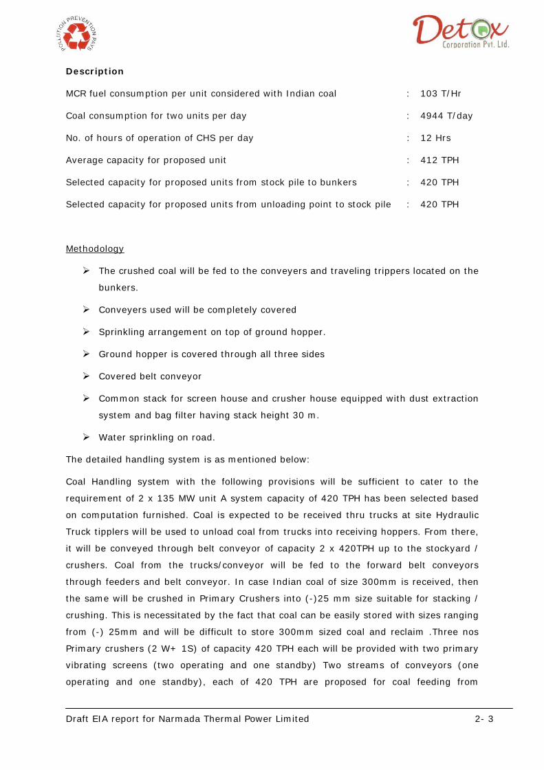
Draft EIA report for Narmada Thermal Power Limited 2- 3
Description
MCR fuel consumption per unit considered with Indian coal : 103 T/Hr
Coal consumption for two units per day : 4944 T/day
No. of hours of operation of CHS per day : 12 Hrs
Average capacity for proposed unit : 412 TPH
Selected capacity for proposed units from stock pile to bunkers : 420 TPH
Selected capacity for proposed units from unloading point to stock pile : 420 TPH
Methodology
The crushed coal will be fed to the conveyers and traveling trippers located on the
bunkers.
Conveyers used will be completely covered
Sprinkling arrangement on top of ground hopper.
Ground hopper is covered through all three sides
Covered belt conveyor
Common stack for screen house and crusher house equipped with dust extraction
system and bag filter having stack height 30 m.
Water sprinkling on road.
The detailed handling system is as mentioned below:
Coal Handling system with the following provisions will be sufficient to cater to the
requirement of 2 x 135 MW unit A system capacity of 420 TPH has been selected based
on computation furnished. Coal is expected to be received thru trucks at site Hydraulic
Truck tipplers will be used to unload coal from trucks into receiving hoppers. From there,
it will be conveyed through belt conveyor of capacity 2 x 420TPH up to the stockyard /
crushers. Coal from the trucks/conveyor will be fed to the forward belt conveyors
through feeders and belt conveyor. In case Indian coal of size 300mm is received, then
the same will be crushed in Primary Crushers into (-)25 mm size suitable for stacking /
crushing. This is necessitated by the fact that coal can be easily stored with sizes ranging
from (-) 25mm and will be difficult to store 300mm sized coal and reclaim .Three nos
Primary crushers (2 W+ 1S) of capacity 420 TPH each will be provided with two primary
vibrating screens (two operating and one standby) Two streams of conveyors (one
operating and one standby), each of 420 TPH are proposed for coal feeding from

Draft EIA report for Narmada Thermal Power Limited 2- 4
stockpile to bunkers. The crushed coal will be fed to the bunkers of the boiler through
series of conveyors and traveling trippers located on the bunkers
The proposed coal stock yard will have a storage capacity of about 75,000 tonnes of coal
which is approximately 30 days’ requirement.
Coal unloaded into the unloading hoppers will be evacuated by the belt conveyor and fed
on to either of the Vibrating Screens in the Crusher House. Inline magnetic separator
and Metal Detector will be provided on belt conveyor at the entry to crusher house.
Vibrating Screens are used for screening out (-) 25 mm coal present in the feed.
The (-) 25 mm coal from the Vibrating Screens will be directly fed on to the Belt
Conveyor. The Coal of size above 25 mm from Vibrating Screens will be fed into either of
the Crushers ( 3 x 50% capacity) for crushing it down to (-) 25 mm size.
The crushed coal will be fed to the bunkers of the boiler through series of conveyors and
traveling trippers located on the bunkers. Whenever coal bunkers are full and the
unloading of trucks is necessitated by the arrival of coal, crushed coal will be stacked in
the stack yard neatly by Dozers. In the absence of non availability of Stacker and Coal
from the stack yard will be reclaimed by front end loader / bull dozers and loaded to
ground hoppers for further feeding to bunkers.
The coal storage area will be provided with necessary fire hydrant system and dust
suppression system.
2.3.2.2 Diesel Oil:
Light diesel oil will be used during starting and High Speed will be used for stabilization.
Pulverised fuel type boiler/ CFBC are preferred because of its proven performance and
very effective combustion in tangential firing. Light diesel Oil / HSD will be used as start
up and stabilization fuel upto 30% BMCR. LDO /HSD will be sourced from nearest depots
of Oil Companies.
The fuel oil requirement of 2 x 135 MW unit shall be procured from nearest depot to the
site and shall be stored in tanks of 2 x 500 KL capacity for HSD and 1 x 200 KL capacity
for LDO. The dyke shall be equipped with dyke and fire fighting equipments.
2.4 FUEL ANALYSIS
The coal analyses for Indian and Imported coal is as mentioned below
Table 2.3 Analysis of coal
Parameters Unit Indian Coal Imported Coal
C % 34.43 46.0
H2 % 2.26 3.48

Draft EIA report for Narmada Thermal Power Limited 2- 5
S % 0.4 0.9
N2 % 0.75 0.86
O2 By Difference % 12.16 7.76
Total Moisture % 10 33
Ash % 40 8
Total % 100 100
Grin debility Index - 50 >50
Coal size will be of less than 50 mm size. As the coal will have to be pre-crushed to a
size of 0 - 25 mm suitable for Boiler firing, the requirement of further crushing is very
less compared to the Indian Raw Coal, which will have a size upto 300 mm.
Table 2.4: Analysis of HSD
Characteristics Result
Total Sulphur content 4.5% (Max)
Gross Calorific Value About 10300kCal/kg
Flash Point (Min.) 66º C
Water content by Volume (Max.) 1.0 %max
Sediment by weight (Max.) 0.25%
Asphaltene content by weight (Max.) -
Kinematic Viscosity in centistokes at 50
Deg.C
169
Ash Content by weight (Max.) 0.1%
Acidity (in inorganic) Nil
Pour Point (Max.) 24º C (Max.)
Sodium Content --
Vanadium Content 25 ppm
Specific heat (kCal/kg. Deg.C) 0.5
Table 2.5: Analysis of light diesel oil
Characteristics Results
Pour Point (Max.) 12º C & 18º C for Summer
and Winter respectively
Kinematic viscosity in Centistokes at 38 Deg.C 7.5
Water content, percent by volume (Max.) 0.25

Draft EIA report for Narmada Thermal Power Limited 2- 6
Sediment percent by mass (MAX.) 0.25
Total sulfur percent by mass (Max.) 0.5
Ash percent by mass (Max.) 0.01
Carbon residue (Rans bottom) percent by wt. (Max.) NA
Acidity in organic Nil
Flash point (Min.) (Pensky Martens) closed cup 66º C
Acidity, total, mg of KOH/g (Max.) Nil
Copper strip corrosion for 3 hours at 100 Deg.C. Not worse than No.2
Gross Calorific Value About 10,400 kCal/kg
2.5 PROCESS DESCRIPTION
The Plant will primarily consist of Two Pulverized fuel fired Boiler or Circulating fluidized
Bed Combustion (CFBC) boilers and Two Steam Turbine Generator with all other
equipments and systems. Light diesel oil will be used during starting and High speed oil
will be used for stabilization. Pulverized fuel type boiler is preferred because of its proven
performance and very effective combustion in tangential firing. The power plant will be
based on the traditional RANKINE CYCLE which is being used in almost all power plants.
It is proposed to have steam parameters of 140 atm pressure at 540 ± 5 ° C
temperature. The feed water temperature entering economizer will be 240 deg c.
Process and Control Mechanism
Steam Turbine Generators (STG) are the main assembly in the Power Plant. Indian/
Imported Coal shall be used as main fuel in the STG. The steam generator(s) shall be
Pulverised coal fired Boilers or Circulating fluidized Bed Combustion (CFBC) boilers.
The steam generator shall receive the water from specialized Water Treatment System
(DM plant); which shall convert raw water to soft water suitable for the steam generator
application. The steam generated will be passed through the Turbine attached to it
wherein the steam will rotate the coil of turbine in magnetic field to produce electricity.
This electrical energy will be supplied at step-up transformer; from where, it is
transmitted at high voltage to step-down transformer for distribution.
Part of the steam shall be used to regenerate the feed water temperature and thereby
improve the thermodynamic cycle efficiency. The steam during this process gets cooled
and then; it shall pass through Air Cooled Condenser. This condensate so formed shall
be pumped back with pumps to the deaerator and then to the steam generator.
The coal combustion will emit exhaust gases, which shall be passed through an
Electrostatic Precipitator, which will reduce the emission levels before passing out

Draft EIA report for Narmada Thermal Power Limited 2- 7
through the chimney. The ash generated from the steam generator shall be sent through
a high-pressure pneumatic system to transfer ash to a silo.
The major equipments of the proposed Power Plant are:
1. Pulverized coal fire Boiler/ Circulating fluidized Bed Combustion (CFBC) boilers (2
nos.)
2. Steam Turbine Generator (STG)
3. Air Cooled Condensor
In addition to these three main equipments, the plant will have all necessary auxiliary
system such as recirculating water system, water dematerializing plant, fire fighting
system and electrical system including power distribution equipment.
2.6 MAJOR MECHANICAL EQUIPMENTS & AUXILIARIES/ UTILITY
The Proposed units of the thermal station will be designed to operate at rated conditions
with coal as main fuel. The layout consists of station building, fuel storage and handling
system, closed cooling water system, switchyard and other auxiliary buildings.
2.6.1 Steam Generator
The steam generator will be pulverised coal fired or CFBC, single reheat, dry bottom,
balanced draft, for outdoor installation. Natural circulation steam generator has been
considered keeping In view the abrasive quality of coal, Boiler design will also be suitable
for variable pressure operation from 30% to 100% BMCR with 15% throttle margin as
well as constant pressure mode of operation. Steam generator will be capable of running
on two shifts and cyclic duty operation. Boiler will be designed to use 100% Indian coal /
100 % Imported coal / blending of Indian coal and Imported coal in any desired
proportion.
The main parameters at 100% BMCR will be as follows:
1. Main steam flow at superheater outlet: 440 t/hr
2. Pressure at superheater outlet: 137 ata
3. Temperature at SH outlet: 540°C
4. Pressure at Reheater outlet: 21.7ata
5. Temperature at SH outlet: 540°C
6. Feed water temp, at economizer Inlet: 240 °C (indicative)
The steam generator will consist of a front wall fired or corner fired, water cooled
furnace, radiant and convection superheaters, attemperator, reheaters, economizer,
rotary airheaters, primary air fans, forced draft fans, induced draft fans, fuel oil pumps,

Draft EIA report for Narmada Thermal Power Limited 2- 8
oil burning and heating equipment, coal mills with associated coal feeders, coal burners,
etc. The type of mills will be bowl mill or ball and race mill or tube mill, which will be
decided during the detailed engineering. Electrostatic precipitators and fly ash hoppers
with associated piping will be provided for the collection of ash. Soot blowers will be
provided at strategic locations and will be designed for sequential automatic operation
from the control room.
The steam generator will be designed to maintain the rated superheater steam
temperature control over the range of 40 to 100% BMCR. Similarly the reheat steam
temperature control range will be between 60 to 100%. The superheater & reheater
desuperheating station will have provision for spraying water tapped off from feed water
piping / BFP interstage tap-off. The steam generator will be provided with a set of soot
blowers with remote automatic sequential operation arranged for on-load cleaning of the
various heat transfer surfaces. The steam for the soot blowers will be taken from the
secondary superheater outlet after the pressure reducing station.
Two nos. of Steam Coil Air Pre-Heater (SCAPH) will be provided at the outlet of each F.D.
fan, and will be installed close to the regenerative air heater. The SCAPH is of modular
construction type with oval fin tubes. The SCAPH will be designed to maintain the
average metal temperature of regenerative air pre-heater cold elements 10°C above the
acid dew point temperature by increasing the temperature of air during start-up and
very low load operation. The regenerative air preheater is of Trisector vertical type. The
air heater will be leak proof and relatively maintenance free. These air preheaters will be
designed passively to avoid the low temperature corrosion of the cold end section of the
air heater parts.
2.6.2 Auxiliary Steam System
Unit will be provided with auxiliary pressure reducing and de-superheating stations
(PRDS) taking the steam tap offs from MS line. The high capacity auxiliary PRDS will be
designed for an ultimate capacity of 30 T/hr approx. auxiliary steam. The auxiliary steam
parameters will be 16 kg/cm2 (abs) pressure and 210°C temperature.
Unit will have its own auxiliary steam header whereas for station services, common
steam header is also envisaged. Arrangement will also be provided to meet the mill fire
fighting requirements.
2.6.3 Turbine and its auxiliaries
The scope of TG unit of 2 x 135 MW will broadly cover the turbine and its integral
systems like Control Oil system, Lube oil System, Automatic Turbine Run-up System,
Bypass system, Condensers, Condenser Air Evacuation system, complete Regenerative
Feed Heating system, Condensate Pumps with drives, Boiler Feed Pumps with drives, LP

Draft EIA report for Narmada Thermal Power Limited 2- 9
Chemical Dosing system, Auxiliary Equipment cooling water system, Instrumentation
and Control devices, equipment and systems such as Turbine Supervisory Instruments,
Turbine Protection and Interlock system, Automatic Turbine Testing system etc
The steam turbine will be of tandem compounded regenerative, condensing,
multicylinder design with common HP and LP casing and directly coupled to the
generator suitable for indoor installation. Double casing turbine design will be preferred.
The turbine will be designed for constant pressure operation and will be suitable for
variable pressure operation. Depending on the capability of the machine, alternative for
over pressure operation will be considered. The turbine will be suitable for cyclic
operation although it is intended for base load operation. The turbine will be provided
with suitable margins for VWO flow. It will have the following design and duty conditions:
Maximum continuous rating at the generator terminals (excluding
the power required for excitation in case of static excitation system
: 135 MW
Turbine throttle steam pressure : 135 kg/sq.cm
Turbine throttle steam temperature : 535° C
Turbine reheat steam temperature : 535° C
Design ambient air temperature : 41 °C
Turbine speed : 3000 rpm
Frequency variation : + 3% to – 5% (47.5
Hz to 51.5 Hz)
Number of extractions for regenerative feed water heating : 5
Final feed water temperature : 240° C
2.6.4 Air Cooled Condenser
The condenser will be air cooled condenser designed as per the requirements of heat
exchange Institute Standards for Steam Condensers, API 661 and ASME. The materials
used willl be conforming to acceptable and reputed material specifications and standards.
The condenser will be sized to condense the maximum quantity of exhaust steam (i.e.
when the extraction is minimum) and will be adequately sized ' to cater to all conditions
of operation such that condenser will never be a bottleneck at any stage of operation.
The exact condenser parameters will be optimized on the basis of site data and most
economical combination of cooling surface and circulating water quantity. The condenser
will be designed as per HEI. The ACC will be suitable for outdoor installation. The ACC
will be direct air cooled type with forced draft. The noise levels will meet with the OSHA
requirements. The ACC will be of 'A' frame type supported on RCC frame. The

Draft EIA report for Narmada Thermal Power Limited 2- 10
arrangement of the ACC will be in 2 rows preferably, with seven modules on each row
.The air flow control through the ACC will be through fan's speed control with two speed
motors or single speed motor with VFD. Automatic tube cleaning system will be
provided.
Condenser Design Criteria:-
i) Design ambient air temperature 41 °C max
ii) Design back pressure 0.176 kg/cm2 (abs)
2.6.5 Auxiliary Cooling System
A hybrid system comprising of fin fan cooler & Auxiliary cooling tower will be provided for
each unit. The generator air cooler, oil coolers of the turbo-generator, boiler feed Pump,
fan in boiler etc. will be supplied with cooling condensate in a closed cycle water system
comprising of DM water, Fin fan cooler, CCW pumps, overhead tank arrangement for the
initial filling and its make-up requirement, Auxiliary cooling tower and a plate heat
exchanger. The pH value of cooling water will be maintained by chemical injection. In
view of maximum ambient temperature prevailing at 41°C, one no cooling tower with a
plate heat exchanger has been included to supplement the cooling effect in order to suit
the cold water requirement of coolers in BTG auxiliaries. The Cooling tower make up
water can be met from soft water from DM plant or service water depending on the
quality of raw water.
2.6.6 Furnace
The furnace will be radiant, dry bottom type with tangential firing (in case of corner fired
type) and enclosed by water cooled, all welded membrane walls communicating with
headers at top and bottom. The furnace bottom will be suitable for installation of dry
type bottom ash hopper. Necessary sealing arrangement will be provided at the bottom
of the furnace to suit dry ash handling. The superheater tubes will be a combination of
radiation and convection type. Single stage of spray type attemperator is envisaged to
control the superheater outlet temperature for varying loads. Economizer will be non
steaming type and will be of modular construction so that if required, addition of loops is
possible. To take care of high erosion properties of coal, sufficient erosion allowance will
be provided on heat transfer surfaces
2.6.7 Air and Flue Gas System
A balanced draft system will be adopted. There will be two (2) axial FD fans, 2 nos. axial
PA fans or individual PA fans for each mill and two (2) radial ID fans. Efforts will be made
to use power saving device like variable frequency drive, two speed motor or hydraulic
coupling (whichever works out to be techno economically most suitable at the detailed

Draft EIA report for Narmada Thermal Power Limited 2- 11
engineering stage) for ID fan drive mechanism. Rotary type air pre-heaters will be used
for the secondary air and primary air. Bypassing of Air heaters will be adopted during
cold startup to avoid cold end corrosion. Alternatively suitable material will be selected
for cold end elements to avoid cold end corrosion.
The draft fans for the steam generator will be capable of maintaining balanced draft
condition in the furnace over the entire load range. The steam generators will be
supplied with a complete set of draft equipment including forced draft fan, induced draft
fan, primary air fan, seal / cooling air fan, damper and associated equipment. Two (2)
nos of 60% PA fan will be provided. The primary air fan will have the following suggested
margins.
Margin on volume: 25%
Margin on pressure: 30%
The draft plant for steam generator will be suitable for producing balanced draft with
sub-atmospheric pressure conditions for furnace. 2 x 60% FD and ID fan with all
auxiliaries. The sizing of fans will be based on the following margins over calculated
values at maximum duty conditions.
FD fan will be of constant speed, horizontal, axial type, Controlled by means of inlet vane
control whereas the ID fan will be of radial centrifugal type with control by means of
hydraulic coupling and inlet vanes. For each FD & ID fans forced oil lubrication system is
provided, which will consist of lube oil pumps, oil cooler, oil reservoirs, piping, valves,
duplex strainer etc. PA fans will be backward curved, radial fan with differential vane
control at the inlet of the fans. All necessary regulating and isolating dampers will be
provided for each fan for safe & efficient operation.
2.6.8 Fuel Oil Burning System
Startup and warm up will be done by LDO and low load operation will be done by HSD
The HSD system will be sized to meet 30% BMCR. Boiler will be so designed that oil
firing for flame stabilization will not be required beyond 30% MCR when firing coal of the
range specified. Necessary pumps, filters and heaters will be provided. The burners, air
registers etc. will have independent pneumatic drives and the entire operation of purging
and fuel sequencing, removal and blow off will be automatic. Scanners and burners will
be of retractable type when not in operation. Ignition of heavy oil will be directly by high
energy arc igniters. There will be light oil (HSD) firing in at least one burner elevation
having a minimum capacity of 7.5-10 % BMCR to facilitate a cold startup of the unit.
HSD system will be sized for 30% BMCR capacity of Boiler.

Draft EIA report for Narmada Thermal Power Limited 2- 12
2.6.9 Soot Blowing System
The system will have short retractable rotary wall blowers for the furnace and long
retractable rotary blowers for the superheater, and economizer. . Fully automatic
sequentially controlled microprocessor based steam soot blowing control system, com-
plete with provision for Individual operation of any soot blower, and facility to bypass
any soot blower, will be provided.
2.6.10 Air Extraction System
Each unit shall comprise of (2x100%) vacuum pumps with all accessories for condenser
air evacuation. The mechanical vacuum pumps and accessories shall be used to create
vacuum by removing air and non-condensable gases from steam condenser during plant
operation.
2.6.11 Lube Oil System
Turbine generator will have a complete self contained lubrication oil system. The system
will cater to the lubrication requirements of the bearings of turbine generator, supply oil
to the hydraulic turning gear (if applicable) during start-up and shut down and jacking
requirements during turning gear operation, under emergency condition.
The system will specifically include the following:
The main oil pump will be centrifugal or gear type and will be driven by the turbine. It
will have sufficient capacity to handle lube oil requirement of the bearings and
emergency seal oil requirements.
During start up and shut down, the oil requirement of TG set will be met by 1x100% AC
driven auxiliary oil pumps.
These pumps will draw oil directly from the main oil tank and discharge oil into the
pressure oil line and continue in service till the main oil pump takes over the oil supply.
A DC driven emergency lube oil pump will be provided to meet bearing lubrication
requirements under low lube oil pressure caused by failure of other pumps.
One (1x100%) AC motor driven and one (1x100%) DC motor driven jacking oil pumps
will be provided to lift the rotor at the bearing during turning gear operation. The pumps
will take suction from main oil tank.
The oil for lubrication will be cooled in (2x100%) oil coolers. The cooling medium will be
DM water (condensate quality).A lube oil purification unit will be permanently purifying
20% of the total oil charge in the system per hour on a continuous bypass basis. Each
unit will be complete, self contained with centrifuge, explosion proof motors, motor
driven feed pumps, heaters etc. Turbine set will be provided with a main oil tank of

Draft EIA report for Narmada Thermal Power Limited 2- 13
sufficient capacity to allow about 8 oil changes per hour to liberate entrained air.
Connection to the centralized lube oil storage & purification system will be provided for
storing and purifying oil from unit lube oil tanks and also transferring new oil to the lube
oil tanks.
2.6.12 HP / LP Bypass
HP/ LP bypass system will be provided for the 135 MW Turbine.
The HP/LP bypass or Turbine bypass station shall be capable of meeting the following
requirements:
• Quick startup of the steam generator from cold, warm and hot conditions.
• Parallel operations of the bypass with turbine in the event of large load throw off.
• House load operations followed by large load throw off.
• To keep the steam generator in operation to avoid a fire out in the steam generator
following full load rejection.
The HP/LP bypass system shall be sized for 60% of BMCR (steam flow at rated main
steam conditions. The HPLP bypass will be sized for steam inlet conditions (pressure and
temperature) in HRH line as those corresponding to 60% MCR.
2.6.13 Boiler Feed Pumps
It is proposed to have a 2 x 100% motor driven boiler feed pumps per unit with the
booster pumps mounted on the common shaft. Each pump will be designed to deliver
440 T/hr feed water at pressure of 160 Kg/cm2(g) {tentative). One feed pump will be
capable of meeting the full requirement of the boiler turbine unit with the other pump as
a standby. Boiler feed pump will be located at ground floor, and will be accessible to
turbine house EOT crane for erection and maintenance. The feed pump will be able to
handle feed water of PH 8.5 to 9.5 and of temperature upto 185-deg.C. The boiler feed
pumps will be of horizontal, centrifugal type, stiff shaft design fitted with mechanical
seals. The boiler feed pumps outer casing will be of barrel type with end rotor removal.
The inner pump assembly comprising of shaft, Impellers, stage casings will be capable of
being removed and replaced as a unit without disturbing the feed piping. Each feed
pump will be provided with ARC type recirculation valve to protect the pump under low
flow condition. The boiler feed water system will be designed to operate primarily on an
automatic mode over the range of system design loads. The arrangement will provide
automatic start-up of the standby pump under conditions like working oil pump failure,
discharge header pressure low etc. The feed flow will be controlled by throttling the feed
control valve whereas hydraulic coupling will be utilized to achieve speed control to
motor driven pumps. Provision will be made for warm up of stand by pump
Draft EIA report for Narmada Thermal Power Limited 2- 14
2.6.14 Condensate Pumps
Each unit will have 2x100% capacity motor driven condensate extraction pumps (one
operating and one standby). The condensate pumps will be horizontal centrifugal type,
multistage, centrifugal diffuser design with a double suction first stage designed for
condensate extraction service having low suction head requirement, one pump will be
capable of handling the condensate from the condenser together with feed heater drains
when the machine is operating at VWO with 3% make-up and discharging this quantity
through the condensate polishing unit and the LP heaters to the deaerator, The pump
will have adequate margins on capacity and head to cater for most adverse conditions of
operation such as
• Turbine bypass in operation
• HP heaters out of service and unit operating at its maximum load during an under
frequency operation
2.6.15 Electric Power Supply System
There are number of C&l systems and equipment which have to be powered in a plant.
The reliable and good quality AC power supply can only be provided by uninterrupted
power supply system. Another important aspect which has to be kept in mind while
finalizing the electrical power supply philosophy is the importance of segregation of the
power supplies so as to avoid common mode failures on account of power supplies,
Faults. In view of this, it is envisaged to provide following electric power supply system
for this project:
Uninterrupted power supply (UPS) system to feed the important C&l package loads
including DDCS, back up secondary instruments, annunciation system, and oxygen
analyzers etc. In addition to the C&l package loads, the peripherals for SG package C&l
system, and TG package C&l system would also be fed from this UPS. The UPS would
consist of 2x100% chargers & 2x100% Inverters, 100% battery banks, and 2x100% DC
distribution &. 2x100% AC distribution boards.
DC emergency backup power supply system would be provided for CLCS & OLCS
hardware consisting of 100% battery bank, 2x100% chargers & 2x100% DC distribution
boards.
2.7 POWER EVACUATION
It is envisaged to evacuate the balance of power after utilizing the power within the plant
for power plant auxiliaries to the state electricity grid through the nearest 220kV
substation at Suva after utilizing the power within the plant for power plant auxiliaries.

Draft EIA report for Narmada Thermal Power Limited 2- 15
2.8 ENVIRONMENT PARAMETERS
2.8.1 WATER
Source
The main source of water to the plant will be from Luwara Branch Canal by Sardar
sarovar Narmada Nigam Ltd. The water allocation letter from the same is attached
herewith as annexure 4.
Water storage
• The plant water for the project will be taken from the Luwara Branch Canal by
Sardar sarovar Narmada Nigam Ltd through properly sized pipe lines. The piping
will be sized adequately to cater water for the entire plant consumption including
future expansion.
• River water received from water intake system will be stored in a reservoir of
40000 m³ capacities (15days’ storage to take care of any stoppage in supply
system).
Water consumption and waste water generation
The major water requirement in the operation of power plant will be for DM water for
boiler, cooling, service water, domestic use etc
Fresh water quantity of 1997.48 m3/day for the proposed project shall be obtained from
Luwara Branch canal. The major consumption of water will be in boiler for steam
generation and make up water for cooling.
The detailed water balance diagram showing the water consumption and waste water
generation for the entire power plant is as given in chapter 4, section 4.4, page 4-11.
2.8.2 Air Pollution Control Equipments
2.8.2.1 Electrostatic precipitators
It is proposed to install high efficiency electrostatic precipitators to limit the outlet
emission to 50 mg/Nm³ while the boiler is operating at its MCR, firing worst coal having
maximum ash content. The electrostatic precipitators will have two (2) parallel gas
streams, isolated from each other on electrical as well as gas side. Gas tight dampers
will be provided at inlets and outlets of each stream so as to allow maintenance to be
carried out safely on the faulty stream, while the unit is working. ESP specific collection
area will not be less than 220 m2/m3 /sec at 100% BMCR and worst coal firing condition.
Electrostatic precipitators will be provided with microprocessor based programmable type
rapper control system and ESP management system to ensure the safe and optimum
operation. Opacity meters will be provided at the ESP outlet for performance
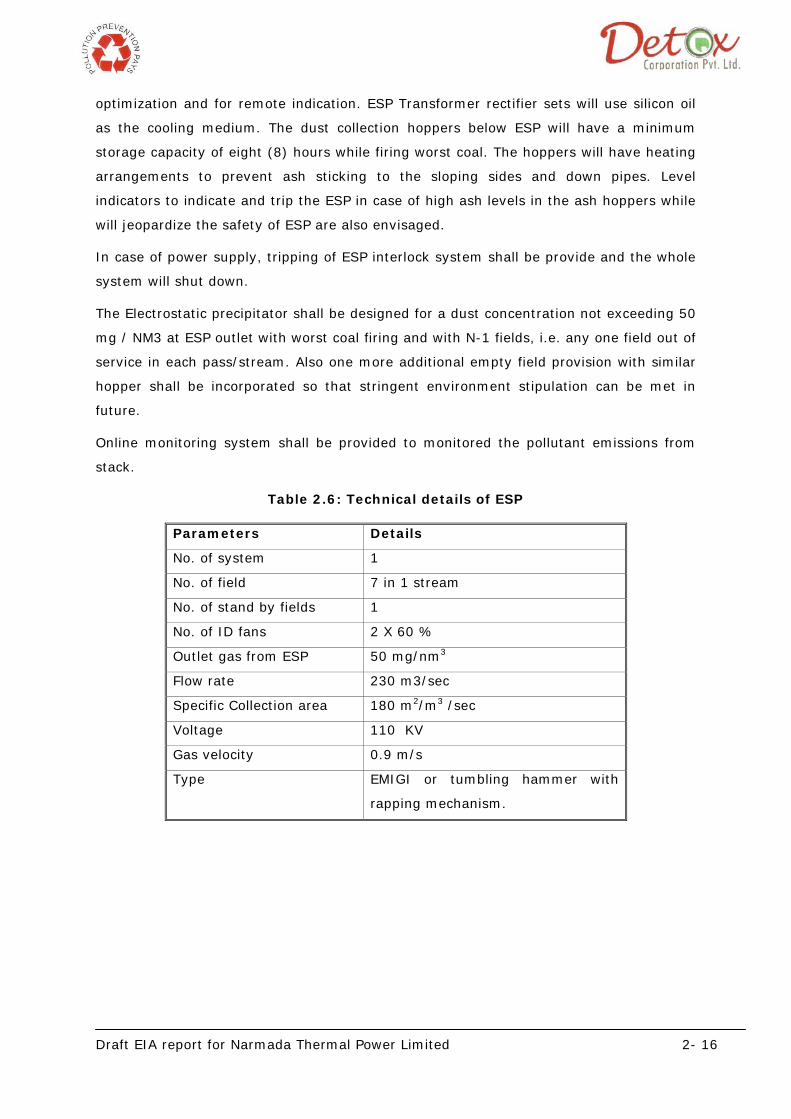
Draft EIA report for Narmada Thermal Power Limited 2- 16
optimization and for remote indication. ESP Transformer rectifier sets will use silicon oil
as the cooling medium. The dust collection hoppers below ESP will have a minimum
storage capacity of eight (8) hours while firing worst coal. The hoppers will have heating
arrangements to prevent ash sticking to the sloping sides and down pipes. Level
indicators to indicate and trip the ESP in case of high ash levels in the ash hoppers while
will jeopardize the safety of ESP are also envisaged.
In case of power supply, tripping of ESP interlock system shall be provide and the whole
system will shut down.
The Electrostatic precipitator shall be designed for a dust concentration not exceeding 50
mg / NM3 at ESP outlet with worst coal firing and with N-1 fields, i.e. any one field out of
service in each pass/stream. Also one more additional empty field provision with similar
hopper shall be incorporated so that stringent environment stipulation can be met in
future.
Online monitoring system shall be provided to monitored the pollutant emissions from
stack.
Table 2.6: Technical details of ESP
Parameters Details
No. of system 1
No. of field 7 in 1 stream
No. of stand by fields 1
No. of ID fans 2 X 60 %
Outlet gas from ESP 50 mg/nm3
Flow rate 230 m3/sec
Specific Collection area 180 m2/m3 /sec
Voltage 110 KV
Gas velocity 0.9 m/s
Type EMIGI or tumbling hammer with
rapping mechanism.

Draft EIA report for Narmada Thermal Power Limited 2- 17
2.8.2.2 Bag filters
To control fugitive emissions in different area of operation bag filter is installed. Capacity
of same is mentioned in the table below.
Table 2.7: Bag filter details
Parameters Details
Capacity 24000 m3/hr
Nos. of system 1
Nos. of bags 180
Diameter 160 mm
Length 3000 mm
Air to cloth ratio 1.51
Filteration area 270 m2
Dust loading of outlet gas
from bag filter
50 mg/Nm3
Dust cleaning system Pulse jet air
2.8.2.3 Provision of future Installation of flue gas de sulphurising system
(FGD)
Space provision for the FGD system, to be installed in future (if required), will be kept
behind the chimney. The design and layout of steam generator and its auxiliaries will be
such that a wet/dry flue gas de-sulphurisation system can be installed in future, taking
suction from duct after ID fan and feeding the de-sulphurisation flue gases back to the
chimney with provision for bypassing the FGD system.
2.8.3 Solid Waste
The solid waste generated shall be fly ash and bed ash. The total quantity of ash
generated is as mentioned below:
Total ash generated :
:
1977 MT/day with Indian coal
287 MT/day with Imported coal
The impact and the management plan for the same including detail ash handling and
disposal system are discussed in chapter 4 & 5 respectively.

Draft EIA report for Narmada Thermal Power Limited 2- 18
2.9 UTILITIES
2.9.1 Raw Water Treatment Plant:
This plant meets the make up water requirement of steam generator auxiliary boiler and
consists of pre treatment plant followed by a demineralization plant. the fresh water
from the storage tank will be filtered in the pre treatment plant with M.G filter, ultra
filter and micro cartridge filter after proper chlorination followed by dechlorination before
supply to DM plant.
For 2 units DM water requirement will be 84 m³/hr. One day’s requirement will have to
be met in 18 hrs’ of operation of DM plant. The DM water requirement is mainly for
boiler make up 27 m3/Hour and CCW make up is only 0.2m3/Hour.
Hence two streams of ion exchange units each with a normal capacity of 164.44 m³/hr
consisting of cation, anion, degasser and mixed bed units with associated regeneration
system are proposed. Exact layout depending on the influent quality of permeate water
will be decided later. Each stream will operate for 18 hours a day.
The effluent of the WT plant will have a conductivity of less than 0.1 micro-mhos/cm at
20 °C and total dissolved solids (TDS) not more than 0.2 ppm in which silica content is
not higher than 0.02 mg/1 as SiO2. The Demineralised water will be stored in two DM
water storage tanks each of 300 m³ capacity (to meet 24 hrs’ requirement of the plant).
3 x 50% capacities pumps each of 20 m³/hr capacity for 2 x 135 MW unit capacities with
two working and one standby, are proposed to pump the DM water to the DM make up
tank.
Individual M.S. rubber lined pipelines are proposed to the condensate storage tanks. Two
100% capacity makeup pumps each of 70 m³/hr capacity with one working and one
standby are proposed to pump the DM water to CST from DM make up tank through
individual rubber-lined pipe lines. Equipment for phosphate, hydrazine, morpholine or
ammonia dosing consisting of dilution tanks, preparation tanks and metering pumps will
be provided for internal water treatment of boiler feed system to prevent scaling and
corrosion of the system components.
2.9.1.1 Raw Water Chlorination System
Chlorine will be dosed in raw water in order to control organic matter and ensure
suitability of water for downstream use. Raw Water Chlorinators draw Chlorine from
Chlorine cylinders. Raw water chlorination will be done at the inlet to MGF before UF
module.

Draft EIA report for Narmada Thermal Power Limited 2- 19
2.9.1.2 Service Water System
Water will be drawn from raw water reservoir for service water system, potable water
system & fire water system. Service water will be pumped with the help of 2 x 100%
service water transfer pumps to an Overhead service water tank of capacity about 300
m³. Further distribution for various points of use will be done from this tank by gravity
except for boiler floor wash for which the water will be pumped using booster pumps.
This system mainly supplies water required for dust suppression in the coal handling
areas, air washer and air conditioning system makeup, air preheater washing (in case of
regenerating type) , plant washing, gardening and toilets.
2.9.1.3 Potable Water System
The quality of drinking water required for the plant is filtered and chlorinated water. The
main source of potable water is from raw water storage tank. Necessary pre treatment
system will be provided to convert raw water into potable quality water. Two 100%
capacity pumps, one working and one standby each of 5 m³/hr are envisaged for
supplying the plant potable water.
2.9.1.4 Closed Cooling Water System
Each unit will be provided with a hybrid system of auxiliaries cooling system. The hybrid
system proposed consists of 2 sets circulating pumps, Finfan coolers, Expansion tank,
chemical dosing system, Cooling tower etc., 2 x 100% capacity Closed cooling water
pumps each of 1400m³/hr and 30 m head will be provided for aux.cooling system . The
total capacity of water will be based on the amount of heat to be removed from the
condenser and on the allowable temperature rise of the circulating water while passing
through the coolers. The hot water from coolers will be passed thru’ a Fin fan cooler for
exchanging heat to the ambient air. The cold water from Fin fan cooler will be passed
thru’ another Plate heat exchanger where cooling effect will be supplemented by cold
water circulated from a Cooling tower of 700 m³/hr capacity in order to bring down the
temperature of cold water inlet to BTG auxiliaries as required by BTG auxiliaries. This
arrangement is necessitated by the fact that during summer the cold water outlet from
Finfan cooler may not meet the exact requirement. The cooling tower will be of induced
draft, multi-cell design and counter flow type with 2 x 100 % Circulating pumps.
Thecapacity of cooling tower will be based on amount of water required to be cooled and
for a cooling range of 9°C. The cooling tower will be of FRP construction. The make up
for the losses in the cooling tower will be made up from the soft water system in DM
plant through adequately sized pumps. The quantity of makeup will depend upon the
cycle of concentration to be maintained in the CW system. Side stream filters and
chemical dosing will be provided for CTs.

Draft EIA report for Narmada Thermal Power Limited 2- 20
2.9.2 Effluent Treatment Plant
Guard pond and oil separators shall be installed as part of ETP scheme. The waste water
generated from plant washing and oil unloading area washing will mainly consist of oily
waste water which shall be treated by passing though oil separators.
The waste water from all the other streams shall be taken to neutralization pit wherein
pH correction will be done and the stream shall later be drawn to guard pond. The
dilution of waste water shall be done in the guard pond and later the water will be used
for gardening, coal handling and dust suppression, plant washing etc. The quality of
water in guard pond shall confirm to the statutory requirement. The detail treatability
study of same is discussed in chapter 4.
Neutralization pit will be provided for 110 m3 considering the retention time of 12 hrs.
Skimmer tank volume will be of 2 m3 considering retention time 30 minutes which shall
be sufficient to cater the total load of waste water.
2.9.3 D G SET
D G set of 500 KVA shall be installed at project site as stand by arrangement. 45 lit/day
LDO/ HSD will be used as fuel. The stack height of the same will be 7 m.

Draft EIA report of Narmada Thermal Power Limited 3-1
Chapter -3 Baseline Environmental Status
The pre project environmental quality in the vicinity of a site identified for proposed
industrial development was collected as the baseline status and also for identification of
significant environmental concerns/ impacts corresponding to project area. The baseline
environmental quality is assessed through field studies within the impact zone for
various individual components of environment, viz. Air, Noise, Water, Land, Biological
and Socio-economic. The present Rapid Environmental Impact Assessment study
comprised pre-project environmental quality monitored during summer season within 10
km around the proposed site. The field surveys for all environmental components were
accomplished during study period for assessment of baseline environmental status.
3.1 AIR ENVIRONMENT
The quality of air depends on the meteorological conditions, back ground concentration
of the pollutants and the emission source. Based on the existing air environment, the
impact due to the upcoming project is quantified. The baseline air environment is studied
within 10 Km radius from the proposed project site during summer season (March - May
2011) and the results are tabulated in this section.
3.1.1 Design Network for Ambient Air Quality Monitoring Stations
The following criterion was taken into account in the design of ambient air quality
monitoring network:
The priority area for air monitoring/samplingwas identified by considering the
predominant wind direction and wind speed (source: Indian Meteorological Department),
topography / terrain of the study area, density of population within the region,
residential and sensitive areas. Meteorological data at the project site during study
period is an essential requirement for proper interpretation for baseline air quality status
and same is also useful in prediction of impacts through mathematical models.
3.1.2 Meteorology Station
Meteorological study is a crucial part in Environmental Impact Assessment Study. In
order to assess the background environmental conditions a weather monitoring station
was installed at a height of 3 m above the ground level in the project vicinity for
continuous recording of micro meteorological parameters like wind speed, wind direction,
cloud cover, rainfall, air temperature and relative humidity. This site is free from

Draft EIA report of Narmada Thermal Power Limited 3-2
hindrance and open from all direction. The collected meteorological data during summer
season were analyzed for hourly variation.
The following meteorological parameters were recorded during the study period:
• Wind speed
• Wind direction
• Temperature
• Humidity
• Rainfall
• Cloud Cover
Temperature
Average temperature in the study area varied between 17oC to 43oC during the study
period. Mean daily variation of maximum, minimum and average temperature were
recorded at site during March-May 2011.
Relative Humidity
Relative humidity in the study area was found varied between 12 % to 91 %. Mean daily
variation of maximum, minimum and average Humidity at site was also recorded.
Pressure
The air pressure in the study area was observed to vary between 1001 hpa to 1016 hpa
during March-May 2011. Mean daily variation of maximum, minimum and average
Pressure at site was recorded during study period.
Wind Speed
The wind speed in the study area was observed between Calm to 13.61 m/s. The
average wind speed in the area was observed 2.54 m/s. Mean daily variation of
maximum, minimum and average Wind speed at site was recorded during study period.
Wind Direction
From the wind rose diagram it is observed that predominant wind direction is SW to NE
and the windrose diagram 3.1.
Rainfall
No rainfall observed in the study area during the study period.
Cloud cover
In the study area, clear weather prevails in most of the time during study period.

Draft EIA report of Narmada
Figure 3.1: W
3.1.3 One season AAQ dat
Ambient air quality was mo
standard guidelines of CP
parameters such as PM10, P
Thermal Power Limited
ind Rose Diagram of Summer Season 2
ta
onitored twice in week for 24 hourly ave
PCB and NAAQS. The conventional and
PM2.5, Sulphur Dioxide (SOx), and oxides o
3-3
2011
erage basis as per
d project specific
of nitrogen (NOx),

Draft EIA report of Narmada
were monitored at different
site during the study period.
3.1.3.1 Air monitoring Sta
Overall 4 locations were iden
site (salt pan) and four in su
study area is occupied by mu
this portion of the study area
Fig
Hence the monitoring locatio
of the project site.
The air monitoring locations
condition in the study area,
at a height of minimum 3 m
depicted on the study area m
Thermal Power Limited
monitoring location around 10 Km radius
ation
ntified for study of air quality including a st
urrounding villages. A North West and sout
ud flats and salt pans. No villages and habi
a.
gure 3.2: Air sampling locations
ons of were selected in the immediate sur
were also selected considering the prevail
the nearby road networks. The sampling s
m above the ground level. The air monito
map as given below in 3.2 (table 3.1).
3-4
s from the project
tation near project
th west part of the
itation observed in
rroundings villages
ing meteorological
station was placed
oring locations are
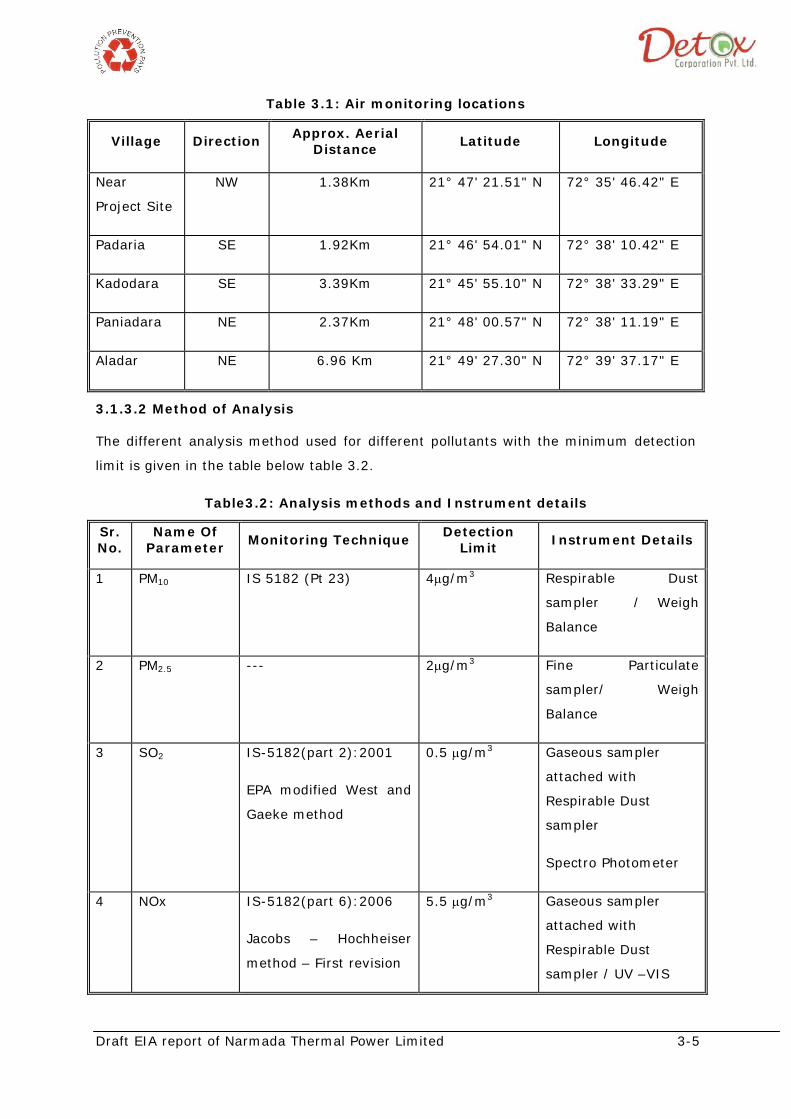
Draft EIA report of Narmada Thermal Power Limited 3-5
Table 3.1: Air monitoring locations
3.1.3.2 Method of Analysis
The different analysis method used for different pollutants with the minimum detection
limit is given in the table below table 3.2.
Table3.2: Analysis methods and Instrument details
Village Direction Approx. Aerial Distance
Latitude Longitude
Near
Project Site
NW 1.38Km 21° 47' 21.51" N 72° 35' 46.42" E
Padaria SE 1.92Km 21° 46' 54.01" N 72° 38' 10.42" E
Kadodara SE 3.39Km 21° 45' 55.10" N 72° 38' 33.29" E
Paniadara NE 2.37Km 21° 48' 00.57" N 72° 38' 11.19" E
Aladar NE 6.96 Km 21° 49' 27.30" N 72° 39' 37.17" E
Sr. No.
Name Of Parameter Monitoring Technique
Detection Limit Instrument Details
1 PM10 IS 5182 (Pt 23) 4μg/m3 Respirable Dust
sampler / Weigh
Balance
2 PM2.5 --- 2μg/m3 Fine Particulate
sampler/ Weigh
Balance
3 SO2 IS-5182(part 2):2001
EPA modified West and
Gaeke method
0.5 μg/m3 Gaseous sampler
attached with
Respirable Dust
sampler
Spectro Photometer
4 NOx IS-5182(part 6):2006
Jacobs – Hochheiser
method – First revision
5.5 μg/m3 Gaseous sampler
attached with
Respirable Dust
sampler / UV –VIS

Draft EIA report of Narmada Thermal Power Limited 3-6
3.1.3.3 Baseline Data
The Ambient Air Quality monitoring results are tabulated for the monitored locations and
presented in the following sections. The observed 24-hour Minimum, Maximum and
average value of PM10, PM2.5 SO2, NOx, concentrations have been presented in table 3.3.
Table 3.3: Analysis methods and Instrument details
PM10
The peak PM10 24-hours average concentrations in the study area were observed in the
range of 73 to 112μg/m3, with the average mean values in the range of 83to95 μg/m3.
At Station A1&A2windward directions shows air quality slightly higher side suggesting
significant agricultural based localised air quality impacts in the surrounding villages,
which are however average values are lower than that of the NAAQ standard (100
μg/m3) (figure 3.3).
Spectro Photometer
Parameters
Observed values
SAMPLING LOCATIONS
CPCB Limits Near
Project Site
Padaria Kadodara Paniadara Aladar
PM10
Min 73 80 47 79 18 100 Max 103 112 109 97 90 Avg 83 95 90 86 51 98 percentile 98.4 110 104 95.16 85.9
PM2.5
Min 31.1 33 26.9 32.7 20.2 60 Max 34.7 35.3 35.5 34.6 34.2 Avg 33.1 34 34.1 33.6 27.2 98 percentile 34.5 35.3 35.4 34.6 33.7
NOx Min 12 12 12 11 9.27 80 Max 19 20 20 18 16.40 Avg 14.71 15.8 15.50 13.75 12.89 98 percentile 18.54 20 19.54 17.8 16.40
SO2 Min 4 4 4 4 2.83 80 Max 9 9 10 9 6.10 Avg 6.8 6.38 6.29 6.17 4.46 98 percentile 8.54 9 9.54 9 6

Draft EIA report of Narmada Thermal Power Limited 3-7
Figure3.3: Measured Ambient PM10 concentration (μg/m3)
PM2.5
The minimum and maximum value for PM2.5 was found between 20.2to 35.5µg/m3, with
the avarage values ranges between27.2 to 34.1μg/m3 which is lower than that of the
NAAQ standard (60 μg/m3) (figure 3.4).
Figure 3.4: Measured Ambient PM2.5 concentration (μg/m3)
0
20
40
60
80
100
120
Nr. Pro. Site Padariya Kadodara Paniyadara Aladar
Concen
tration, µg/m3
Sampling location
PM10 level in the study area
Minimum
Maximum
Average
0.0
5.0
10.0
15.0
20.0
25.0
30.0
35.0
40.0
Nr. Proj. Site
Padariya Kadodara Paniyadara Aladar
Concen
tration, µg/m3
Sampling Location
PM2.5 level in the study area
Minimum
Maximum
Average

Draft EIA report of Narmada Thermal Power Limited 3-8
NOx
The nitrogen oxide concentration in the study area varied between 11 to 20 µg/m3, with
the mean values in the range of 12.89 to 15.8μg/m3 which is lower than that of the
NAAQ standard (80 μg/m3) (figure 3.5).
Figure3.5: Measured Ambient NOX concentration (μg/m3) SO2
The maximum average concentration of sulphur dioxide in the study area was observed
as 10µg/m3 where as the minimum 2.83 µg/m3 and average value ranges between
6.8µg/m3 to 6.17 µg/m3 (figure 3.6).
Figure3.6: Measured Ambient SO2 concentration (μg/m3)
0.00
5.00
10.00
15.00
20.00
25.00
Nr. Proj. Site
Padariya Kadodara Paniyadra Aladar
Minimum
Maximum
Average
0
2
4
6
8
10
12
Nr. Pro. Site Padariya Kadodara Paniyadra Aladar
Concen
tration, µg/m3
Sampling Location
SO2 level in the study area
Minimum
Maximum
Average