draft amendment to fire detection and suppression systems
TRANSCRIPT
Page 1 of 28
Dated of hosting on website:-26th
April, 2021
Draft Amendment
to
AIS-135 Fire Detection and Alarm System (FDAS) &
Fire Detection and
Suppression Systems (FDSS) for Buses
Comments if any, may please be forwarded on email:-
[email protected] within period of thirty days.
Page 2 of 28
Date of hosting on website: ………….2021
Draft Amendment 1
to
AIS-135 Fire Detection and Alarm System (FDAS) & Fire Detection and
Suppression Systems (FDSS) for Buses
1. Page III, INTRODUCTION
After first paragraph of introduction, insert following text
Under the guidance of the Ministry of Road Transport and Highways (MORTH) and
project proposal based on experiments carried out by DRDO for introduction of
protection of occupants from fire, panel under Automotive Industry Standards
Committee (AISC), has prepared this amendment to notified standard AIS-135.
Presently fire detection, alarm and suppression systems are notified for fires originating
from engine compartment vide AIS-135. Provisions regarding protection of occupants
from fire under this amendment are aimed at proving an additional evacuation time to
the occupants and thus will further enhance the safety in fire incidents in buses through
FPS and FAS.
A significant majority of fatal and non-fatal injuries to passengers in bus fire accidents on Indian roads are due to heat and smoke in passenger compartment irrespective of origin of fire in the vehicle. The fatal and non-fatal injuries to passengers in bus fire accidents on Indian roads can be prevented if, irrespective of origin of fire in the vehicle, the heat and smoke in occupant compartment is controlled and thus providing an evacuation window to the occupants.
2. Page 1/35, clause 1.0
Substitute following text Scope for existing text of Scope
“1.0 SCOPE
1.1 This standard specifies the guidelines for detection and suppression
systems for fires that may originate from engine compartment of buses and
protection system from heat and smoke in occupant compartment.
1.2 This standard applies to
1.2.1 Part I – Fire Detection and Alarm Systems (FDAS)
Approval of Fire Detection and Alarm Systems (FDAS) which are fitted in
engine compartment of Buses.
1.2.2 Part II – Fire Detection and Suppression Systems (FDSS)
Approval of Fire Detection and Suppression Systems (FDSS) which are
fitted in engine compartment of Buses.

Page 3 of 28
1.2.3 Part III – Occupant compartment Fire Alarm Systems (FAS) for school bus and
buses of Type III category as per AIS-052 (Rev. 1) as amended from time to
time.
Approval of systems which are fitted in Buses to detect the presence of fire,
smoke and /or heat in occupant compartment and provide alarm.
1.2.4 Part IV – Occupant compartment Fire Protection Systems (FPS) for school bus
and buses of Type III category as per AIS-052(Rev. 1) as amended from time
to time.
Approval of systems which are fitted in Buses to protect the occupants from
fire, heat and smoke to provide sufficient time for their safe evacuation.
1.3 Buses fitted with FDAS, FDSS, FAS and FPS shall comply with the
requirements of this standard.
1.4 The requirements of this standard shall not be applicable for Electric
Powertrain Vehicles (EVs).”
3. Page 5/35, Part II
Add following Parts III and IV after Part II
“PART III
Requirements of Fire Alarm Systems (FAS)
for bus occupant compartment
1.0. DEFINITIONS
For the purpose of Part III of this standard,
1.1 Fire Alarm System (FAS) - A system comprising of components and
sub-systems required for automatically detecting fire, heat and /or smoke
in occupant compartment and initiating an automatic alarm.
1.2. Occupant Compartment - for the purpose of this standard occupant
compartment means the compartment / space inside a vehicle designed for
occupant occupancy including driver‟s seating area.
1.3. Fault Signal - A distinctive audible and visual signal indicating occurrence
of a fault within the FAS (for example, break in electric circuit, short circuit
or fault in power supply, mechanical damage in detector or elsewhere in
system).
1.4. Alarm Signal - An audio and visual signal initiated by a smoke alarm-
initiating device, such as a fire alarm box, automatic fire detector, or
other device in which activation is indicative of the presence of a smoke
as fire signature.
1.5. Fire detection system type - for the purpose of type approval as
a component means a category of systems which does not essentially differ in
the following aspects:
Page 4 of 28
a) Detection system;
b) Detector;
c) ECU.
1.6. Smoke- The airborne solid and liquid particulates along with gases evolved
due to pyrolysis or combustion of materials, together with the quantity of air
that is entrained or otherwise mixed into the mass.
1.7. Heat Detector - A heat detector is a sensor that senses either abnormally
high temperature or rate of temperature rise, or both, coupled with smoke
detector.
1.8. Smoke Detector - A smoke detector is a sensor that senses the presence of
significant amount of smoke as fire signature.
1.9. Class A Fire – A fire in occupant compartment involving all possible
ordinary solid combustibles present there.
1.10. False Alarm: A false alarm, is the deceptive or erroneous signal of an
emergency, causing unnecessary panic and/or involvement of specialized
resources when they are not needed.
2.0. APPLICATION FOR CMVR APPROVAL
2.1. Application for CMVR type approval for a vehicle type in respect of the
Fire Alarm Systems (FAS) in Occupant Compartment of buses.
2.1.1. The application for approval of:
(a) A vehicle type or;
(b) A vehicle type fitted with bodywork type approved as a technical unit.
(c) A component type with regard to its constructional features shall be
submitted by the manufacturer or by his duly accredited
representative.
2.1.2. It shall be accompanied by the documents containing the information
specified in Annex IA & IIIA as applicable.
2.1.2.1. Detailed description of the vehicle type with regard to the arrangement and
design of the control or of the unit on which the fire alarm system
acts.
2.1.3 A vehicle representative of the type to be approved shall be submitted to the
approval agency.
2.1.4 A vehicle not comprising all the components proper to the type may be
accepted provided that it can be shown by the applicant to the satisfaction of
the approval agency that the absence of the components omitted has
no effect on the results of the verifications, so far as the requirements of this
standard are concerned.
2.1.5 In case of application for approval of a type of vehicle, the manufacturer shall
also provide the following information about installed FAS:
2.1.5.1 A copy of the analysis regarding the installation of the FAS (see Annex
IVA) in case FAS is approved as a component, or
Page 5 of 28
2.1.5.2 An analysis on regarding the installation of the FAS (see Annex VIA) in
case FAS is installed in a specific occupant compartment.
3.0 MODIFICATION AND EXTENSION OF APPROVAL OF A
VEHICLE OR BODYWORK TYPE
3.1 Every modification of the vehicle, bodywork type or fire alarm system
shall be notified to the test agency which approved the type. That test agency
may then determine that: (see Annex VIII)
Either that the modifications made are unlikely to have an appreciable
adverse effect and that, in any case, the vehicle, bodywork or fire
detection system still complies with the requirements; Or require a further
test of compliance from the manufacturer.
4.0. GENERAL REQUIREMENTS
4.1 Vehicles shall be equipped with fire alarm system detecting fires in the
occupant compartment based on sensors that get provide a signal of
presence of fire either through smoke or abnormally high temperature / rate
of temperature rise, or both. The detectors forming part of FAS shall have
dust compensation feature and conform to relevant IS/UL/FM Global
Standard.
4.2 Upon detection of fire in occupant compartment, the system referred in
clause no 4.1, shall provide the driver and passengers with both an acoustic
and a visual signal, and activate the hazard warning signal. The placement of
the visual alarm shall be such that it is visible unobstructed while viewed
from the driver seat.
4.3 The occupant compartment fire alarm system shall be operational irrespective
of whether engine has been started and the vehicle's altitude.
4.4 The installation of the fire alarm system shall comply with the following
requirements;
4.4.1. The fire alarm system shall be installed according to the system
manufacturer's installation manual.
4.4.2 An fire risk analysis shall be conducted prior to the installation in order
to determine the location of fire detectors and alarm system. Potential
fire hazards within the occupant compartment shall be identified such
that the fire detectors shall be positioned to appropriately cover the fire
hazard. The system shall also be ensured to work properly regardless of the
vehicle‟s altitude, road conditions etc.
4.5. Minimum sound level of audio-visual alarm shall be 90 dB(A) to make it
audible to the passenger seated on rear seats of the bus. Optionally hooter
system as approved under AIS-052(Rev. 1) can be used with minimum
sound level of 90 dB(A).
4.6 Further, to the FAS required in the occupant compartment by this standard,
the additional heat sensors to monitor temperature near fuel tank and/or near
wheel braking system may be installed as enhanced fire safety measures.
Page 6 of 28
PART IV
Approval of Bus Occupant Compartment
Fire Protection System (FPS)
1.0. DEFINITIONS
For the purpose of Part IV of this standard,
1.1 Fire Protection System (FPS): Fire Protection System is a low pressure
water mist system comprising of necessary elements to manually trigger
release of water mist, with specific characteristics, capable of suppressing the
designed class A fire in occupant compartment as well as controlling the
temperature inside the occupant compartment, when origin of fire is not
occupant compartment, to provide atleast three minutes of evacuation
window to the occupants.
1.2 "Approval of a vehicle, or a separate technical unit or a component"
means the approval of a vehicle type, or of bodywork or of a component type
with regard to the constructional features specified in this Standard;
1.3 "Fire Protection System" for the purpose of type approval as a
component means a category of bus systems which does not essentially differ
in the following aspects:
(a) Compartment(s) for passengers including drivers‟ cabin;
(b) Maximum gross volume upto 80m3;
(c) General layout of components in the compartment (i.e. position of fire
hazards determined and limited to maximum no of seats for a given
volume).
(d) Marking of exit routes, combustion heater and engine on the layout
(e) Number and type of extinguishing agent discharge point(s) (e.g. nozzle/
mist generator atomizer) used ;
(f) Stored dry air as propellant gas or alternative mechanism, including
pump, to generate desired water pressure at discharge point."
1.4. „Occupant Compartment‟ means the compartment / space inside a vehicle
designed for passenger occupancy including driver‟s cabin, if any.
1.5. Water Mist System –A distribution system connected to a water cylinder as
atomizing media through suitable number of nozzles capable of delivering
water mist that meets the performance requirements as per this standard.
1.6. Propulsion System – a system when activated shall be able to provide water
in the piping network at constant nozzle operating pressure for specific time
either using air propulsion system including high pressure air cylinder,
pressure regulating valve and solenoid valve or any such similar arrangement.
1.7. Pressure Relief Valve - A device designed to prevent pressure levels in
excess of the design pressure of the system and/or, the system components.
1.8. Low Pressure System. A water mist system where the water distribution
piping is exposed to pressures of 12.1 bar (175 psi) or less.
Page 7 of 28
2.0. APPLICATION FOR CMVR APPROVAL
2.1 The application for approval of:
(a) A vehicle type with fire risk analysis or;
(b) A separate technical unit type or;
(c) A vehicle type fitted with bodywork type already approved as a
separate technical unit as per this part of the standard with type approval of all
its components type with regard to its constructional features working at
higher than atmospheric pressure shall be submitted by the manufacturer or
by his duly accredited representative.
2.2 It shall be accompanied by the documents containing the information
specified in Annex IIA and IIIA.
2.3 Detailed description of the vehicle type with regard to the arrangement
and design of the control or of the unit on which the fire protection
system acts.
2.4 A vehicle or fire protection system representative of the type to be approved
shall be submitted to the test agency.
2.5 A vehicle not comprising all the components proper to the type may be
accepted provided that it can be shown by the applicant to the satisfaction of
the test agency that the absence of the components omitted has no
effect on the results of the verifications, so far as the requirements of this
standard are concerned.
2.6 In case of application for type approval of a bus, the manufacturer shall also
provide the following information regarding the occupant compartment fire
protection system, if applicable:
2.6.1 A copy of the analysis on regarding the installation of the FPS in case of a
fire protection system (FPS) approved as a component (see Annex VA) or
2.6.2 An analysis on regarding the installation of the FPS in case of a fire
protection system (FPS) installed in a specific occupant compartment, (see
Annex VIIA)
3.0. MODIFICATION AND EXTENSION OF APPROVAL OF A
VEHICLE OR BODYWORK TYPE
3.1 Every modification of the vehicle, bodywork type or fire protection
system shall be notified to the test agency which approved the type. That test
agency may then determine that: (see Annex VIII)
Either that the modifications made are unlikely to have an appreciable
adverse effect and that, in any case, the vehicle, bodywork or fire
suppression system still complies with the requirements; Or require a
further test of compliance from the manufacturer.
4.0. GENERAL REQUIREMENTS
4.1 The requirements of this Part of the standard have been formalized based on
the evaluation of the efficacy of water mist system in occupant compartment
of standard size bus, in case of
Page 8 of 28
a. Seat surface fire inside the occupant compartment where the
suppression is achieved through experiments.
b. External fire affecting occupant compartment of buses, where cooling
and scavenging is achieved, in simulation studies, to ensure an
evacuation window of at least three minutes to the occupants.
4.2 In the buses irrespective of having engine located either to the front
or rear, the occupant compartment shall be equipped with a fixed fire
protection system for life safety of occupants. Thus providing the driver an
option to use fire fighting system to flood the compartment with water mist to
control the temperature and smoke inside the occupant compartment for a
defined period of time. This time window shall be used for evacuation of
passengers to safety. The hazard warning signal include acoustic and a visual
signal indicting presence of fire/smoke or event of sensing either abnormally
high temperature or rate of temperature rise, or both, in the occupant
compartment or in each sub-compartments, as the case may be.
4.3 In addition to the fire alarm system, vehicles shall be equipped with a fire
protection system in the occupant compartment as well as in each sub-
compartments within the occupant compartment.
4.4 The fire alarm system and the fire protection system shall be operational
irrespective of whether engine is running or not and the vehicle's altitude.
This is to ensure availability of FPS in the case of external fire which is
expected to be the most likely cause of transfer of heat and smoke to
occupant compartment. The external fire sources i.e. not originated in
occupant compartment, are fires such as in engine, fuel tank or in braking
system with or without involvement of collision.
4.5 Before finalizing the design and installation details of the FPS, an assessment
of fire risk within the occupant area shall be completed.
4.5.1 For standard bus designs, the primary risk of heat and smoke to occupants
from within the compartment emanates from ignition of class „A‟ materials
present in the form of solid combustibles (wood, fiber boards, seat
cushions/foams, curtains, upholstery etc.) and the total quantity is expected to
be proportional to the number of seats. Excessive loading of combustible
material inside the occupant compartment may have adverse impact on
expected performance of FPS. The risk analysis shall be documented with
approximate quantities of the each source as per clause 4.5.2 below.
4.5.2 The analysis shall take into account at-least the following:
a. amount of each Class A fire source spread over the compartment,
b. identification surfaces where temperatures may reach above 80°C (due to
the auto-ignition temperature for fluids, gases or substances in contact
with the surfaces and electrical components and cables with a current or
voltage high enough for an ignition to occur as well as hoses and
containers with flammable liquid or pressurized gas).
4.5.3 Further analysis shall also be conducted prior to the installation of FPS
in order to determine the location and direction of suppression agent
discharge point(s) (e.g. nozzles, type or water mist discharge tube or other

Page 9 of 28
distribution points). Potential fire hazards within the occupant
compartment and each sub-compartment where a fire risk is present
shall be identified as per clause 4.5.2 and discharge point(s) located such
that the water mist is distributed to cover the fire hazard when the system
activates. The spray pattern and direction of discharge points as well as
the throwing distance shall be ensured to cover identified fire hazards. The
system shall also be ensured to work properly regardless of the vehicle‟s
altitude, road conditions etc.
4.5.4 A low pressure system comprising of atomizer/nozzles, piping network,
water cylinder mounted with pressure relief valve, and connected to water
propulsion system to generate fine mist of desired size and concentration for
specified time is to be installed in the occupant compartment.
4.5.5 The design of FPS comprising of water mist system is recommended to be
based on 0.65 LPM/m3 mist injection rate and accordingly the technical
features with respect to different volume of occupant compartment shall be as
per the table given below. The “seating capacity” is used as a measure of
standard fire load and categorization while highest volume in “gross volume
range” of the occupant compartment is used as a basis for system design for
FPS implementation. When measuring the gross volume of occupant
compartment, the range shall be arrived without subtracting the volume of
installed components / seats etc. from it.
S. No. Seating Capacity
(Maximum)
Gross Volume
Range (m3)
No of Nozzles
(Minimum)
Water Quantity
(Liters)
1. 20 Less than 20 9 55
2. 30 20 to 30 13 80
3. 40 30 to 40 18 110
4. 50 40 to 50 22 130
5. 60 50 to 60 26 155
6. 70 60 to 70 30 185
7. 80 70 to 80 35 210
4.5.6 The design features of the system are based on worst case scenario of
maximum volume in the given gross volume range and lowest water flow
rate accordingly key design parameters i.e. the minimum number of discharge
points /nozzles and mass of water as suppression agent are provided. The
volume and pressure of the propellent gas shall be sufficient to achieve at
least 7 bar constant nozzle operating pressure at farthest point to meet the
following nozzle characteristics.
Nozzle Flow Rate at 7 bar pressure : 1.75 ± 0.25 LPM
Cone Angle : 90° or higher, solid cone
Droplet Size, Souter Mean Diameter
(D32)
: 50 micron or lower
4.5.7 The discharge of water as extinguishing agent shall be along the length of the
bus, in three headers, in such a way that mist is targeted to the seats on left
side, right side with the nozzle spacing upto 1500 mm as well as on the mid-
Page 10 of 28
section of the ceiling for cooling of smoke layer, as per clause 5.0 for
installation of water mist system. The total discharge time of the system shall
not be less than THREE minutes. It is acceptable if the suppression system
has more quantity of extinguishing agent and/or more discharge points and/or
a longer discharge tube for the extinguishing agent and/or more propellant
gas than required according to the table given in clause 4.5.5.
4.5.8 The manual activation of system through control panel, having independent
power backup or auxiliary power back-up as the case may be, will be
positioned in the vicinity of the driver‟s dashboard, in such a manner that
the driver based on one or more of the following inputs, shall be able
remotely activate the FPS through electrically operated solenoid valve on
confirmation of unmanageable fire in occupant compartment after receiving
an audio-visual signal from Fire Alarm System or self-observation / input
from others about presence of an external fire that may affect the lives of bus
occupants.
4.5.9 For ensuring effectiveness of FPS in a non-air conditioned bus, where 50% of
the windows are expected to be open at any given time, the water mist
injection rate has been kept in the range 0.65 litres per m3 per minute or
higher. When applied to an air-conditioned bus the same level of mist
injection rate shall provide additional factor of safety.
5.0 INSTALLATION REQUIREMENTS
5.1 The fire protection system shall be installed according to the system
manufacturer's installation manual.
5.2 To obtain the requisite discharge rate condition, the protection system is to be
assembled within its maximum piping limitations with respect to the
number of fittings, size and length of pipe, if relevant. The water cylinder
shall have applicable capacity or higher and appropriate pressure rating. The
air cylinder or gas cartridge pressurized with propellant gas is expected to
achieve constant operating pressure, with the help of adjustable pressure
reducing valve, for at least 180 seconds or higher.
5.3 The fire protection system shall be installed by the system
manufacturer or supplier based on as-built drawing to show the area where
extinguishing agent discharge points such as of nozzles, extinguishing agent
cylinder or extinguishing agent discharge tubes are located. The discharge
points are recommended to be positioned inside occupant compartment
along the length of the bus, angled downwards or in such a way to provide
wet coverage to window and seats located just below, as the case may be, in
three different headers:
a. Above the windows on right side (RS) of the occupant compartment on
the ceiling or just below the luggage rack.
b. On the ceiling of gang way i.e. mid-section (MS), upto 1.5 times the
spacing being used in RS discharge points.
c. Above the windows on „Left Side‟ (LS) of the occupant compartment, on
the ceiling or just below the luggage rack with an offset upto 750 mm
from similar installations on the RS, wherever possible.

Page 11 of 28
SNo. Seating Capacity No of Nozzles
RS
No of Nozzles
MS
No of Nozzles
LS
1. 20 3 3 3
2. 30 5 4 4
3. 40 7 5 6
4. 50 8 7 7
5. 60 9 8 9
6. 70 11 9 10
7. 80 13 10 12
5.4 The number of discharge points in each LS and RS section shall depend upon
number of seats on each side. Any deviation from the table at clause 5.2
above be justified and recorded. The system set-up and configuration shall be
observed and documented e.g. amount of suppression agent and propellant
gas, system pressure, number, type and location of discharge points, length of
pipes and number of fittings.
5.4.1 Pipe layout network from water cylinder to distribution manifold for
connecting all three headers consisting atomizers to be optimized for pressure
drop.
5.4.2 The pipe network shall be welded / bolted securely at sidewalls or ceiling of
the compartment with support brackets and clamps. The pipe distribution
network shall be installed in such a way so that the entire working fluid in the
pipe network can be easily drained and ease of refilling is achieved.
5.4.3 After completion of the pipe distribution work, the pipe work shall be
hydrostatically tested and performance documented.
6.0 LIMITATION
The design features elaborated in clause 4 & 5 above are applicable to the
standard bus of volume and seat matrix i.e. upto 80m3 and having 80 number
of seats. The buses having special comfort arrangements or sub-
compartments in occupant area shall be subject to simulated fire tests as per
Appendix 6.”

Page 12 of 28
4. Page 8/35, Annex I
Add following Annex IA after existing Annex I
ANNEX IA (See Part III, clause 2.1.2)
INFORMATION TO BE SUBMITTED FOR TYPE APPROVAL OF BUSES
WITH REGARD TO FIRE ALARM SYSTEM (FAS)
S. No Parameter
1. Name of the Model(s)
2. Variant(s)
3. Vehicle category (s)
4. Name and address of vehicle manufacturer
5. Type of fire detector(s) used
6. Number of fire detector (s) for each type
7. Name and address of manufacturer of the Fire detectors
for each type
8. Name and address of manufacturer of the alarm system
and control panel
9. Description of the device installation and sketch
showing locations within occupant compartment and
relevant dimensions of fire detectors
10. Detection Devices provided additionally
Acoustic or visual
If visual, duration and type of optical signal
11. Test report number of the FAS

Page 13 of 28
5. Page 9/35, Annex II
Add following Annex IIA after existing Annex II
ANNEX II A (See Part IV, clause 2.2)
INFORMATION TO BE SUBMITTED FOR TYPE APPROVAL OF BUSES
WITH REGARD TO FIRE PROTECTION SYSTEM
S. No Parameter
1. Name of the Model(s)
2. Variant(s)
3. Vehicle category(s)
4. Dimensions of the occupant compartment
5. Name and address of vehicle manufacturer
6. Make and type of the fire protection system
7. Test report number of the FPS
8. Water reservoir max operational pressure (kg/cm2):
9. Quantity of extinguishing agent (deionized water in
litre):
10. Numbers and characteristics of discharge point(s):
11. Total Length of discharge tube in occupant compartment
12. Number of discharge points(s):
13. Type of propellant gas, dry air cylinder:
14. Stored pressure of propellant gas (dry air)
15. Minimum operating temperature
16. Dimensions of pipes and fittings
17. Detailed description, layout drawings and installation
manual of the fire suppression system and its
components
Page 14 of 28
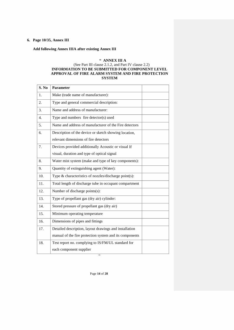
6. Page 10/35, Annex III
Add following Annex IIIA after existing Annex III
“ ANNEX III A (See Part III clause 2.1.2, and Part IV clause 2.2)
INFORMATION TO BE SUBMITTED FOR COMPONENT LEVEL
APPROVAL OF FIRE ALARM SYSTEM AND FIRE PROTECTION
SYSTEM
S. No Parameter
1. Make (trade name of manufacturer):
2. Type and general commercial description:
3. Name and address of manufacturer:
4. Type and numbers fire detector(s) used
5. Name and address of manufacturer of the Fire detectors
6. Description of the device or sketch showing location,
relevant dimensions of fire detectors
7. Devices provided additionally Acoustic or visual If
visual, duration and type of optical signal
8. Water mist system (make and type of key components):
9. Quantity of extinguishing agent (Water):
10. Type & characteristics of nozzles/discharge point(s):
11. Total length of discharge tube in occupant compartment
12. Number of discharge points(s):
13. Type of propellant gas (dry air) cylinder:
14. Stored pressure of propellant gas (dry air)
15. Minimum operating temperature
16. Dimensions of pipes and fittings
17. Detailed description, layout drawings and installation
manual of the fire protection system and its components
18. Test report no. complying to IS/FM/UL standard for
each component supplier
”

Page 15 of 28
7. Page 11/35, Annex IV
Add following Annex IVA after existing Annex IV “ANNEX IVA
(See Part III, Clause 2.1.5.1)
REQUIREMENTS FOR FIRE ALARM SYSTEM (FAS)
APPROVED AS A COMPONENT
1.0. Specifications
1.1 Fire Alarm System (FAS) conforming to this standard shall comply with the
requirements of class A fire and smoke test described in Appendix 6.
1.2 The test apparatus, class A smoke and fire test and general test conditions are
described in Appendix 6 to test the response time of FAS.
2.0. Requirements
2.1 The detectors forming part of FAS shall have dust compensation feature and
conform to relevant IS / UL / FM-Global Standard. The number of detectors
shall be sufficient in numbers that when mounted in the occupant
compartment, with or without partition, will be line of sight to at least
one detector from every class A fire source present in the occupant
compartment, when the bus is empty. This is to ensure optimal coverage of
threats of fire liable to break out in the occupant compartment.
2.2 The numbers of detectors in any FAS may be higher or lower for special
sensors such as multi-sensor type, aspirating type to meet the criteria
mentioned in paragraph 2.5 below.
2.3 The audio-visual alarm unit and control panel, having ingress level protection
of IP54 or higher, will be positioned in the vicinity of the driver‟s
dashboard. Additional audio-visual alarm unit may be installed at the rear of
occupant compartment, if required.
2.4 In addition, provision for manual means of activation of audio-visual alarm
may be incorporated in the control panel as an option.
2.5 The fire shall be detected and warning signal shall be activated within
30 seconds after ignition of test fire #8.
2.6 The test is considered passed if success was achieved at the first attempt or at
two of three attempts in a case when first of these attempts fails.”

Page 16 of 28
8. Page 12/35, Annex V
Add following Annex VA after existing Annex V
“ANNEX V A (See Part IV, clause 2.6.1)
REQUIREMENTS FOR FIRE PROTECTION SYSTEM
(FPS) APPROVED AS A COMPONENT 1.0. Specifications
1.1. Fire protection System (FPS), conforming to this standard, as a component,
shall comply with the requirements of Part IV of this standard.
1.2. The test apparatus for functional test, evaluation of design and
documentation are described in Clause 4.0 of Appendix 6.
2.0. Requirements
2.1 The FPS system key components are type tested and meet all the requirement
of safety, design and operation from this standard to achieve the service
requirements.
2.2 The FPS to be tested for appropriate occupant compartment and to be
activated remotely/manually through an electrical switch positioned in the
vicinity of the driver‟s dashboard, to actuate the connected solenoid valve or
pumping device to perform one or more functional tests in Appendix 6.
2.2 The FPS is expected to achieve intended purpose and considered passed if
compliance is achieved in all the parameters of 12 point check list in Clause
4.1 in Appendix 6.
Note:- For components level tests for Fire Protection System (FPS), please refer
clause no. 4.0 of Appendix 7.
9. Page 15/35, Annex VI
Add following Annex VIA after existing Annex VI
“ANNEX VIA (See Part III, clause 2.1.5.2)
REQUIREMENTS FOR FIRE ALARM SYSTEM (FAS)
INSTALLED IN A SPECIFIC OCCUPANT COMPARTMENT
1.0 Specifications
1.1 A specific occupant compartment means compartments which do not differ
in the following essential aspects:
(a) No of Seats in compartment(s) for occupants including drivers‟ cabin;
(b) Maximum gross volume;

Page 17 of 28
(c) General layout of components in the compartment (i.e. position of fire
hazards determined).
(d) Marking of exit routes, combustion heater and engine on the layout
1.2 The fire alarm system (FAS) conforming to this standard shall comply with
the requirements of class A smoke and fire test.
2.0. Requirements
2.1 The class A smoke and fire test shall be conducted in accordance with
Appendix 6 to test the response time of FAS.
3.0. FAS Installation
3.1 The detectors shall be mounted in the occupant compartment in such a
manner that there will be line of sight to at least one detector from
every class A fire source present in the occupant compartment, when the bus
is empty, to ensure optimal coverage of threats of fire liable to break out in
the occupant compartment.
3.2 The installation of the smoke detectors in occupant compartment without
partition, shall be in such a way that each zone of 3.0 ± 0.5 meters of the bus
length is covered by at least two smoke detectors placed on the ceiling
farthest from each other while maintaining a distance of about 0.8± 0.2 meter
from zone boundary / sides of the bus. This is to provide the maximum
coverage as well as to avoid false alarm from a smoke entering from
windows.
The numbers of detectors in each zone may be higher or lower for special
sensors such as multi-sensor type, aspirating type to meet the criteria
mentioned in paragraph 2.7 below.
3.3 The installation of the smoke detectors in occupant compartment with
partitions, shall be in such a way that each partition is covered by at least two
smoke detectors placed on the ceiling farthest from each other while
maintaining distance of 0.5 meter or more from sides of the bus/partition. The
aim is to provide the maximum coverage within the partition.
3.4 The audio-visual alarm unit and control panel, having ingress level protection
of IP54 or higher, will be positioned in the vicinity of the driver‟s
dashboard in occupant compartment. Additional audio-visual alarm unit may
be installed at the rear of occupant compartment, if required.
3.5 In addition, provision for manual means of activation of audio-visual alarm
may be incorporated in the control panel as an option.
3.6 The fire shall be detected and warning signal shall be activated within
30 seconds after ignition of test fire #8.
3.7 The test is considered passed if success was achieved at the first attempt or at
two of three attempts in a case when first of these attempts fails.”
Page 18 of 28
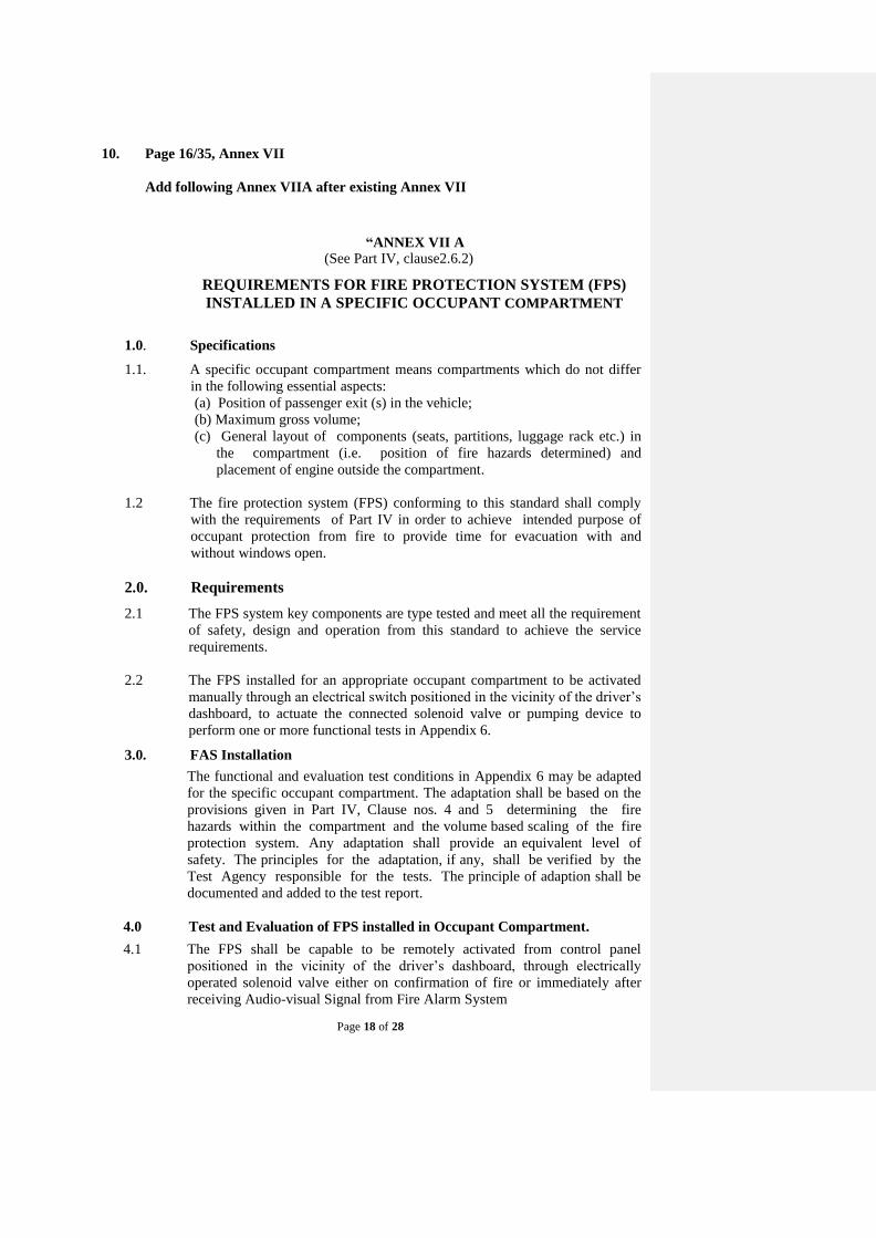
10. Page 16/35, Annex VII
Add following Annex VIIA after existing Annex VII
“ANNEX VII A (See Part IV, clause2.6.2)
REQUIREMENTS FOR FIRE PROTECTION SYSTEM (FPS)
INSTALLED IN A SPECIFIC OCCUPANT COMPARTMENT
1.0. Specifications
1.1. A specific occupant compartment means compartments which do not differ
in the following essential aspects:
(a) Position of passenger exit (s) in the vehicle;
(b) Maximum gross volume;
(c) General layout of components (seats, partitions, luggage rack etc.) in
the compartment (i.e. position of fire hazards determined) and
placement of engine outside the compartment.
1.2 The fire protection system (FPS) conforming to this standard shall comply
with the requirements of Part IV in order to achieve intended purpose of
occupant protection from fire to provide time for evacuation with and
without windows open.
2.0. Requirements
2.1 The FPS system key components are type tested and meet all the requirement
of safety, design and operation from this standard to achieve the service
requirements.
2.2 The FPS installed for an appropriate occupant compartment to be activated
manually through an electrical switch positioned in the vicinity of the driver‟s
dashboard, to actuate the connected solenoid valve or pumping device to
perform one or more functional tests in Appendix 6.
3.0. FAS Installation
The functional and evaluation test conditions in Appendix 6 may be adapted
for the specific occupant compartment. The adaptation shall be based on the
provisions given in Part IV, Clause nos. 4 and 5 determining the fire
hazards within the compartment and the volume based scaling of the fire
protection system. Any adaptation shall provide an equivalent level of
safety. The principles for the adaptation, if any, shall be verified by the
Test Agency responsible for the tests. The principle of adaption shall be
documented and added to the test report.
4.0 Test and Evaluation of FPS installed in Occupant Compartment.
4.1 The FPS shall be capable to be remotely activated from control panel
positioned in the vicinity of the driver‟s dashboard, through electrically
operated solenoid valve either on confirmation of fire or immediately after
receiving Audio-visual Signal from Fire Alarm System

Page 19 of 28
4.2 Fire protection System (FPS) conforming to this standard shall comply with
the requirements of Part IV of this standard within occupant compartment.
4.3 The test apparatus for functional test, evaluation of design and documentation
are described in Clause 4.0 of Appendix 6.
4.4 A declaration by the manufacturer, that an additional test has been conducted
with the water vessel as well as the dry air (propellant gas) vessel cooled to
the minimum operating temperature (“5” degrees celsius) and the discharge
point flow characteristics (Clause 4.3 Appendix 6) were found to be
conforming to the Part IV of the standard, to be submitted.
4,5 The FPS is expected to achieve intended purpose and considered passed if
compliance is achieved in all the parameters of 12 point check list in Clause
4.1 in Appendix 6.”
11. Page 18/35, Annex VIII
Substitute following Annex VIII for existing Annex VIII
“ ANNEX VIII (Clause 3.0 of Parts I & II and Clause 3.1 of Parts III & IV)
GUIDELINES FOR DECIDING WHETHER TESTING IS NEEDED
1. In general, when changes in technical specifications of vehicle do not
affect the FDAS / FDSS/ FAS /FPS performance adversely, and is still
within the stipulated limits, the type approval certificate can be
extended. The changes in parameters that affect the FDAS / FDSS and FAS /
FPS performance are listed in clause No. 2 and 3 respectively.
2. In the case of following changes, with respect to the vehicles tested, in the
details submitted as per Annexures I and II, tests are necessary for
establishing compliance:
1. Change in volume of engine
compartment To be tested if volume of
engine compartment is
increased which increases the
number of nozzles derived
from clause no. 4.5.3
2. Type of extinguishing agents To be tested in case of any change
3. Change in capacity of
extinguishing agent
To be tested in case of
decrease in capacity
4. Dimensions of pipes & fittings
of FDSS & FDAS
To be tested in case of any change
5. Pressurized cartridge system To be tested in case of
decrease in pressure of the
system
3. In the case of following changes, with respect to the vehicles tested, in the
details submitted as per Annexures IA & IIA tests are necessary for
establishing compliance:

Page 20 of 28
1. Change in volume category
of occupant compartment To be tested for compliance as
the change will lead to increase in
the number of nozzles as per
from clause no. 4 & 5 Part IV
2. Exceeding maximum number
of seats corresponding to
specific volume category of
occupant compartment
To be tested with volume
corresponding to applicable seats
which increases the number
of nozzles derived from clause
no. 4 & 5, Part IV
3. Change in water capacity of
extinguishing system
Compliance with Part IV to be
tested
4. Dimensions of pipes &
fittings of FPS
Compliance with Part IV to be
tested
5. Change in Pressurized dry air
cylinder
Compliance with Part IV to be
tested in case of decrease in
stipulated pressure and/or change in
capacity
6. Type, characteristics and
location of the nozzles
Compliance with Part IV to be
tested
7. Type of solenoid valve,
pressure regulating valve,
safety / relief valve
Compliance with Part IV to be
tested
8. Type of detector in FAS or
number of detection zones
To be verified for compliance with
Part III
4. Changes other than the above are generally considered as not affecting
compliance. However it does not limit test agencies and vehicle
manufacturer to investigate possibility of any other criteria, for which tests
may be conducted for extension as per mutual agreement between test
agencies & vehicle manufacturer.”
Page 21 of 28
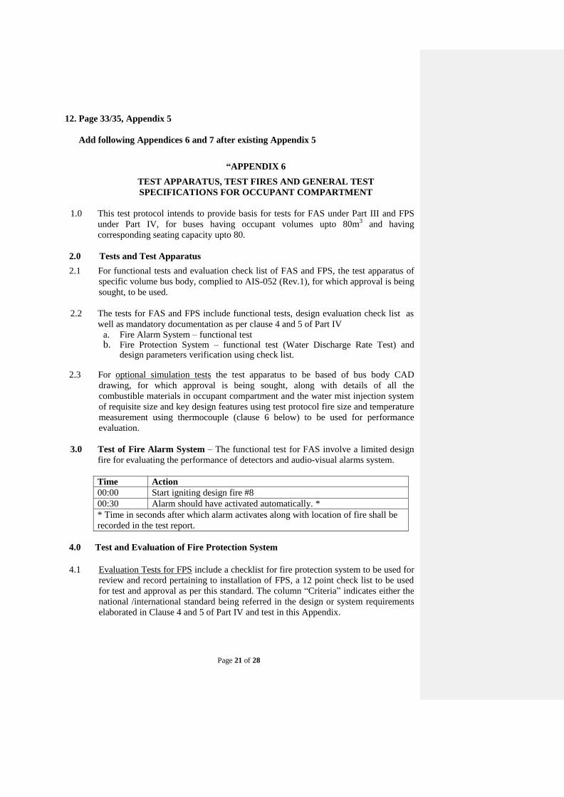
12. Page 33/35, Appendix 5
Add following Appendices 6 and 7 after existing Appendix 5
“APPENDIX 6
TEST APPARATUS, TEST FIRES AND GENERAL TEST
SPECIFICATIONS FOR OCCUPANT COMPARTMENT
1.0 This test protocol intends to provide basis for tests for FAS under Part III and FPS
under Part IV, for buses having occupant volumes upto 80m3 and having
corresponding seating capacity upto 80.
2.0 Tests and Test Apparatus
2.1 For functional tests and evaluation check list of FAS and FPS, the test apparatus of
specific volume bus body, complied to AIS-052 (Rev.1), for which approval is being
sought, to be used.
2.2 The tests for FAS and FPS include functional tests, design evaluation check list as
well as mandatory documentation as per clause 4 and 5 of Part IV
a. Fire Alarm System – functional test b. Fire Protection System – functional test (Water Discharge Rate Test) and
design parameters verification using check list.
2.3 For optional simulation tests the test apparatus to be based of bus body CAD
drawing, for which approval is being sought, along with details of all the
combustible materials in occupant compartment and the water mist injection system
of requisite size and key design features using test protocol fire size and temperature
measurement using thermocouple (clause 6 below) to be used for performance
evaluation.
3.0 Test of Fire Alarm System – The functional test for FAS involve a limited design
fire for evaluating the performance of detectors and audio-visual alarms system.
Time Action
00:00 Start igniting design fire #8
00:30 Alarm should have activated automatically. *
* Time in seconds after which alarm activates along with location of fire shall be
recorded in the test report.
4.0 Test and Evaluation of Fire Protection System
4.1 Evaluation Tests for FPS include a checklist for fire protection system to be used for
review and record pertaining to installation of FPS, a 12 point check list to be used
for test and approval as per this standard. The column “Criteria” indicates either the
national /international standard being referred in the design or system requirements
elaborated in Clause 4 and 5 of Part IV and test in this Appendix.

Page 22 of 28
S.
No.
Test Parameter Criteria
1. Propellant Gas Quality Dry Air standard
2. Propellant Gas Cylinder Capacity and
Operational Pressure
Sufficient to provide 3 mins
system operation
3. Propellant Gas Cylinder Test Pressure Relevant safety code or 1.5
times of operation pressure
whichever is higher
3. Pressure Reducing Valve Required reduction and
lockable adjustment knob
4. Propellant Gas Cylinder Safety Relevant IS standard
5. Solenoid Valve Remote Activation for 3
minutes operation
6. Water Cylinder Capacity and Operational
Pressure
Sufficient to provide 3 mins
system operation
7. Water Cylinder Test Pressure Relevant safety code or 1.5
times of operation pressure
whichever is higher
8. Nozzle Characterization – three parameters
in Clause 4.5.6 Part IV
Certification from BIS
recognized/NABL lab for
each nozzle.
9. Total Nozzles and layout As per clause 5.3 Part IV
10. Pipe Network pressure optimization As per clause 4 & 5 Part IV
11. Pipe & Fittings material & type Relevant Standard and
Record as per Clause 4.2
Appendix 6
12. FPS Functional Test - flow characteristics of
each nozzle for 3 minutes operation
Record as per Clause 4.3
Appendix 6
4.2 Hydrostatic testing of pipe network requires atomizer locations to be plugged before
the test takes place. Each section shall be pressurized upto 1.5 times the working
pressure. During the test no pressures loss to be observed and record to be made. In
the event of leakage, the pressure shall be removed from the system, appropriate
corrective action to be taken and the test procedure to be repeated.
4.3 Functional Test of FPS are intended for checking flow characteristics of installed
Fire Protection System. Each discharge point is wrapped with 10 liters capacity
plastic bag to collect the water during 3 minutes of system operation.
Time Action
00:00 Start FPS
00:10 FPS activation confirmation
03:10 Manual switch off of FPS
* Time in seconds for system operation, normal operational pressure and water
volume at each discharge point, in liters, shall be recorded in the test report.
5.0 Optional Simulated Fire Test for FPS
5.1 Simulated conditions for four fire scenarios are recommended to be used for design
validation, improvements and performance evaluation of FPS using Fire Dynamics
Simulator software (i.e. PYROSIM). The pre-burn time for heat and smoke from
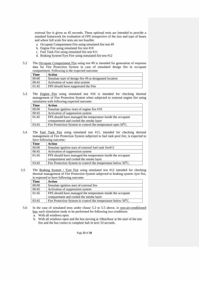
Page 23 of 28
external fire is given as 45 seconds. These optional tests are intended to provide a
standard framework for evaluation of FPS irrespective of the size and type of buses
and where full scale fire tests are not feasible.
a. Occupant Compartment Fire using simulated fire test #9
b. Engine Fire using simulated fire test #10
c. Fuel Tank Fire using simulated fire test #11
d. Braking System/Tyre Fire using simulated fire test #12
5.2 The Occupant Compartment Fire using test #9 is intended for generation of response
data for Fire Protection System in case of simulated design fire in occupant
compartment. Following is the expected outcome:
Time Action
00:00 Simulate start of design fire #9 at designated location
00:45 Activation of water mist system
01:45 FPS should have suppressed the Fire
5.3 The Engine Fire using simulated test #10 is intended for checking thermal
management of Fire Protection System when subjected to external engine fire using
simulation with following expected outcome:
Time Action
00:00 Simulate ignition /start of engine fire #10
00:45 Activation of suppression system
01:45 FPS should have managed the temperature inside the occupant
compartment and cooled the smoke layer
03:45 Fire Protection System to control the temperature upto 500C.
5.4 The Fuel Tank Fire using simulated test #11, intended for checking thermal
management of Fire Protection System subjected to fuel tank pool fire, is expected to
have following outcome:
Time Action
00:00 Simulate ignition start of external fuel tank fire#11
00:45 Activation of suppression system
01:45 FPS should have managed the temperature inside the occupant
compartment and cooled the smoke layer
03:45 Fire Protection System to control the temperature below 500C.
5.5 The Braking System / Tyre Fire using simulated test #12 intended for checking
thermal management of Fire Protection System subjected to braking system /tyre fire,
is expected to have following outcome:
Time Action
00:00 Simulate ignition start of external fire
00:45 Activation of suppression system
01:45 FPS should have managed the temperature inside the occupant
compartment and cooled the smoke layer
03:45 Fire Protection System to control the temperature below 500C.
5.6 In the case of simulated tests under clause 5.2 to 5.5 above, in non-air-conditioned
bus, each simulation study to be performed for following two conditions
a. With all windows open
b. With all windows open and the bus moving at 10km/hour at the start of the test
fire and the bus comes to complete halt in next 10 seconds.
Page 24 of 28
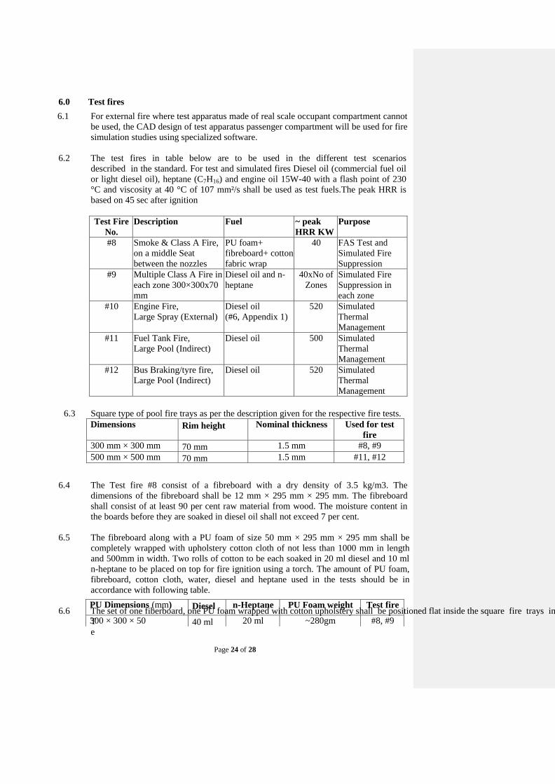
6.0 Test fires
6.1 For external fire where test apparatus made of real scale occupant compartment cannot
be used, the CAD design of test apparatus passenger compartment will be used for fire
simulation studies using specialized software.
6.2 The test fires in table below are to be used in the different test scenarios
described in the standard. For test and simulated fires Diesel oil (commercial fuel oil
or light diesel oil), heptane (C7H16) and engine oil 15W-40 with a flash point of 230
°C and viscosity at 40 °C of 107 mm²/s shall be used as test fuels.The peak HRR is
based on 45 sec after ignition
Test Fire
No.
Description Fuel ~ peak
HRR KW
Purpose
#8 Smoke & Class A Fire,
on a middle Seat
between the nozzles
PU foam+
fibreboard+ cotton
fabric wrap
40 FAS Test and
Simulated Fire
Suppression
#9 Multiple Class A Fire in
each zone 300×300x70
mm
Diesel oil and n-
heptane
40xNo of
Zones
Simulated Fire
Suppression in
each zone
#10 Engine Fire,
Large Spray (External)
Diesel oil
(#6, Appendix 1)
520 Simulated
Thermal
Management
#11 Fuel Tank Fire,
Large Pool (Indirect)
Diesel oil 500 Simulated
Thermal
Management
#12 Bus Braking/tyre fire,
Large Pool (Indirect)
Diesel oil 520 Simulated
Thermal
Management
6.3 Square type of pool fire trays as per the description given for the respective fire tests.
Dimensions Rim height Nominal thickness Used for test
fire
300 mm × 300 mm 70 mm 1.5 mm #8, #9
500 mm × 500 mm 70 mm 1.5 mm #11, #12
6.4 The Test fire #8 consist of a fibreboard with a dry density of 3.5 kg/m3. The
dimensions of the fibreboard shall be 12 mm × 295 mm × 295 mm. The fibreboard
shall consist of at least 90 per cent raw material from wood. The moisture content in
the boards before they are soaked in diesel oil shall not exceed 7 per cent.
6.5 The fibreboard along with a PU foam of size 50 mm × 295 mm × 295 mm shall be
completely wrapped with upholstery cotton cloth of not less than 1000 mm in length
and 500mm in width. Two rolls of cotton to be each soaked in 20 ml diesel and 10 ml
n-heptane to be placed on top for fire ignition using a torch. The amount of PU foam,
fibreboard, cotton cloth, water, diesel and heptane used in the tests should be in
accordance with following table.
6.6 The set of one fiberboard, one PU foam wrapped with cotton upholstery shall be positioned flat inside the square fire trays in such a way that two small rolls of cotton fabric for fire ignition can be placed on top to meet the requirements of test #8. Similar arrangement needs to be made in each zone for test #9. Simulated
T
e
PU Dimensions (mm) Diesel n-Heptane PU Foam weight Test fire
300 × 300 × 50 40 ml 20 ml ~280gm #8, #9

Page 25 of 28
st fire #10 consists of diesel oil spray fires while Test fire #11 & #12 consist of large
oil pool fire (by hot surface ignition).
7.0 Thermocouples in Simulation Studies
7.1 Four thermocouples (Tc) shall be mounted on the surface while another four towards
the ceiling as per coordinates given. At least two (Tc8 & Tc9) over the engine area on
the passenger floor, three (Tc10, Tc11, Tc12) to be placed equidistant from each other
along the length on the ceiling. Here Tc10 & Tc12 will be placed close to ceiling while
Tc11 to be placed 0.5 meter below the ceiling. Further one thermocouple each at main
service door (Tc15) 1.6 meter from floor, at just above the fuel tank (Tc14) and at
emergency exit (Tc13) to be placed along the floor. The coordinates of thermocouple
locations from the front edge of Service door and their temperature in every 30
seconds from start of simulation to be studied for evaluation of FPS.
7.2 The location of the thermocouples is illustrated in figures below.
8.0 Tolerances
8.1 A tolerance of ±5 per cent of the stipulated values shall apply (for time values:
±5 seconds). These tolerances are applicable to test set up parameters only. These
tolerances are not applicable to performance duration (e.g. FAS / FPS performance time
parameters).
APPENDIX 7
GENERAL GUIDELINES
1.0 These Guidelines are being included to facilitate implementation of a reliable fire safety
system during its life cycle. For desired results from proposed FAS and FPS, it is
essential to include reliable components at design stage, adherence to good engineering
practices during installation and regular preventive and breakdown maintenance of the
system during operation. Therefore, it is essential that all the essential communication is
shared with relevant agencies dealing with the system in its different stages. Following
aspects are considered essential for being covered.
a. Components Selection and testing for FAS and FPS
b. Documentation on
i. Maintenance Requirements
ii. Reactivation of FPS after release of water mist
iii. Training Requirements
Thermocouple Coordinates [x; y; z] Thermocouple Coordinates [x; y; z]
Tc8 [x1; y1; 0] Tc12 [x5; y3; z3]
Tc9 [x2; y2; 0] Tc13 [x6; y4; 0]
Tc10 [x3; y3; z3] Tc14 [x7; y5; 0]
Tc11 [x4; y3; (z3-0.5)] Tc15 [x8; y6; 0]
Tc9
Z
Y Tc12
Tc14
Tc13
Tc11 Tc10
Tc15 X
Tc8
Y
Page 26 of 28
2.0 Components Selection and testing for FAS and FPS
2.1 It is recommended that selection of components, even at the initial stage of
implementation, should be based on the overall objective of achieving high system
reliability. To achieve this goal, components of even higher reliability are required.
Initially it is not expected to have reliability data of all the components, however as the
implementation of this standard progresses the reliability is expected to become a
baseline requirement.
2.2 The recommended type testings‟ of components are shock, vibration, cyclic and drop
tests. The component level tests guideline as per AIS-018 are provided below.
SNO TEST DETAILS
2.3 Any of the components, where choice between national/international standard exist, is
recommended to adhere the more stringent standard. Identifying the relevant standards
early on will ensure development of a quality fire alarm system and fire protection
system.
2.4 While selecting the components, routing of cables, wires, pipes etc. a careful
consideration is expected to be given to system safety. Any component which might get
impacted due to tempering by passengers also needs to be suitably protected and/or laid
accordingly. For example, the water mist nozzles may include a protection cap to protect
the nozzles from dust and other blockages over the years. The nozzle protection cap, if
provided, shall be released or ruptured as soon as the pressure is build-up in water
distribution header. Similarly, wherever smoke detectors are being used in FAS, their
installation is to be undertaken in such a way that interference from dust is minimized.
This presents a challenge for non-air-conditioned bus and therefore a specially designed
housing, dust protector along with dust compensation may provide better results and
lower day to day maintenance.
3.0 Documentation
Besides the drawings, installation manual and necessary documentation as part of the
standard, some add-on documentation covering different aspects of maintenance and
training are required to supplement a good engineering design.
3.1 Maintenance Requirements:
There will be a day to day up-keep requirements to keep the system in operational mode.
For example, this may include testing /cleaning of smoke sensors, nozzles, checking of
water in the water cylinder and pressure in the gas cylinder. Then there would be
preventive maintenance to ensure the continued functionality of FAS and FPS which
may include the charging of auxiliary power batteries and step by step method to make
the system functional if the system is not working as intended. The guidelines here are
not exhaustive but only for illustration purposes.
3.2 Reactivation of FPS after release of water mist
Page 27 of 28
The SOP provided by the manufacturer is expected to elaborate on reactivation of FAS
and FPS after a fire incident or accidental actuation.
3.3 Training Requirements –
The FAS and FPS in occupant compartment compliment other fire safety measures such
as already installed FDAS and FDSS in engine compartment and the mandatory portable
fire extinguisher kept on-board the buses. Therefore, the choice of fire safety measure
primarily rests with the driver or the attendant. A bus fire incident (internal or external
to the occupants) in the initial stage can be effectively managed using the portable
extinguishers. Similarly, in case of engine fire, the incident can be effectively managed
using FDSS if detected in time. Making the drivers and attendants to understand their
role in handling different fire scenarios will be the key element to save precious lives of
bus occupants. The manufacturer is expected to clearly spell out the roles of driver and
attendant during operation and maintenance. This followed by regular training and mock
drills to the concerned personnel will alone enable best use of FAS and FPS.
4.0. Guidelines for Component Level Tests (common requirements for FAS & FPS)
4.1 Functional Test: This test is applicable on all electronics devices (e.g. detectors, solenoid valves etc.) of
FAS & FPS system. The component shall be connected to rated voltage. The component
shall be coupled with the suitable rig which can simulate the required function of device.
The maximum current consumption (A) shall be recorded. The maximum current shall
not exceed the values specified by the manufacturer.
4.2 Endurance Test under Vibration Test:
Each electronic component (e.g. detectors, solenoid valves etc.) and the water
pressurization system (WPS) (filled with water) shall be mounted in actual vehicle‟s
orientation with suitable fixture and subjected to following Vibration Tests:-
A. Sine Sweep Vibration Test:
Frequency Range1 : 10 to 30 Hz
Amplitude : ± 2 mm
Frequency Range2 : 30 to 1000 Hz
Acceleration : 2.5g
Sweep Rate : 1 Octave/min.
Test Duration : 1 hr. in each axis (X, Y & Z)
B. Mechanical Shock Test:
Acceleration : 50g
Duration : 11 ms
No. of Shocks : 60 Nos. [20 shocks in each axis {10 positive and 10 negative}]
After performing above vibration tests, the functional check shall be done as per clause
no. 3.1. For WPS, there shall not be any breakage or crack of mountings and other
component
4.3 Endurance Test at High Temperature:
Comment [SD1]: Highlighted text may be
shifted to Appendix 7.

Page 28 of 28
Each electronic component (e.g. detectors, solenoid valves etc.) shall be mounted in
actual vehicle‟s orientation and subjected to endurance test at high temperature in
climatic chamber at temperature of 65 ± 5C for 12,500 cycles.
The mechanical components shall be subjected to high temperature at 100 ± 5C for 240 h.
After performing above tests, the functional check shall be done as per clause no. 3.1.
For mechanical components, there shall not any breakage, crack, discoloration etc.
4.4 Endurance Test at Low Temperature:
Each electronic component (e.g. detectors, solenoid valves etc.) shall be mounted in
actual vehicle‟s orientation and subjected to endurance test at low temperature in
climatic chamber at temperature of -20 ± 5C for 12,500 cycles.
The mechanical components shall be subjected to low temperature at -20 ± 5C for 240
h. The size of test component shall be mutually agreed between test agency and the
manufacturer.
After performing above test, the functional check shall be done as per clause no. 3.1. For
mechanical components, there shall not any breakage, crack, discoloration etc.
4.5 Endurance Test – Salt Spray Test:
Each electronic component (e.g. detectors, solenoid valves etc.) shall be mounted in
actual vehicle‟s orientation and subjected to endurance test while keeping the
component in salt spray chamber with 5% concentration of sodium chloride and internal
temperature of 35°C ± 2°C for 12500 cycles.
The mechanical components (e.g. tubings, connectors, water tank, nozzles etc.) shall be
subjected to salt spray test as per above said specifications for 240 h. The size of test
component shall be mutually agreed between test agency and the manufacturer.
After performing above test, the functional check shall be done as per clause no. 3.1. For
mechanical components, there shall not any corrosion or any other abnormal sign.
4.6 Endurance Test at High Humidity:
Each electronic component (e.g. detectors, solenoid valves etc.) shall be mounted in
actual vehicle‟s orientation and subjected to high humidity test while keeping the
component in a humidity chamber at 95% ± 3% Rh for 12500 cycles.
After performing above test, the functional check shall be done as per clause no. 3.1.
4.7 Drop Test:
Each electronic component (e.g. detectors, solenoid valves etc.) shall be subjected to
drop
and topple test as per Clause 4.10 of IS: 10250-1982 with a drop height of 200 mm. The
number of drops shall be 6 Nos.
After performing above test, the functional check shall be done as per clause no. 3.1.
Also there shall not be any breakage or crack of component.”