draft ac 33.28-2 - faa.gov · ... guidelines for time-limited-dispatch analysis for electronic...
TRANSCRIPT

Subject: GUIDANCE MATERIAL FOR 14 CFR §33.28, RECIPROCATING ENGINES, ELECTRICAL AND ELECTRONIC ENGINE CONTROL SYSTEMS.
Date: 08/13/03 Initiated By: ANE-110
AC No: 33.28-2 Change: Version:
1. PURPOSE. This advisory circular (AC) provides guidance and acceptable methods, but not the only methods, that may be used by designers of reciprocating engine electronic control systems to demonstrate compliance with §33.28 of Title 14 of the Code of Federal Regulations (14 CFR 33.28), Electrical and electronic engine control systems. 2. RELATED REGULATIONS. a. Part 21. Section 21.16. b. Part 23. Sections 23.901, 23.903, 23.909, and 23.1309. c. Part 33. Sections 33.4, 33.5, 33.17, 33.28, 33.49, 33.53 and appendix A of part 33. 3. RELATED REFERENCE MATERIAL. a. ACs, Notices, and Policy. (1) AC 20-53A, Protection of Aircraft Fuel Systems Against Fuel Vapor Ignition Due to Lightning, dated April 12, 1985. (2) AC 20-115B, RTCA, Inc. Document DO-178B, Software Considerations in Airborne Systems and Equipment Certification, dated January 11, 1993. (3) AC 20-136, Protection of Aircraft Electrical/Electronic Systems Against the Indirect Effects of Lightning, dated March 5, 1990.
AC 33.28-2 8/13/03
(4) AC 21-16D, RTCA Document No. DO-160D, Environmental Conditions and Test Procedures for Airborne Equipment, dated July 21, 1998. (5) AC 23.1309-1C, Equipment, Systems, and Installations in Part 23 Airplanes, dated March 12, 1999. (6) AC 33.28-1, Compliance Criteria for 14 CFR §33.28, Aircraft Engines, Electrical and Electronic Engine Control Systems, dated June 29, 2001. (7) Notice N8110.71, Guidance for the Certification of Aircraft Operating in High Intensity Radiated Field (HIRF) Environments, issued April 2, 1998. (8) Engine and Propeller Directorate Policy, Time Limited Dispatch (TLD) of Engines Fitted with Full Authority Digital Engine Control (FADEC) Systems, dated June 29, 2001. (9) AC 33.4-1, Instructions for Continued Airworthiness, dated August 27, 1999. b. Industry Documents. (1) RTCA Document No. DO-160D (EUROCAE ED14D), Environmental Conditions and Test Procedures for Airborne Equipment, dated July 29, 1997. (2) RTCA Document No. DO-178B (EUROCAE ED12D), Software Considerations in Airborne Systems and Equipment Certification, dated December 1, 1992. (3) SAE ARP 926B, Fault or Failure Analysis Procedure, issued June 1997. (4) SAE ARP 1834A, Fault or Failure Analysis for Digital Systems and Equipment, issued June 1997. (5) SAE ARP 4754, Certification Considerations for Highly-Integrated or Complex Aircraft Systems, issued November 1996. (6) SAE ARP 4761, Guidelines and Methods for Conducting the Safety Assessment Process on Civil Airborne Systems and Equipment, issued December 1996. (7) SAE ARP 5107, Guidelines for Time-Limited-Dispatch Analysis for Electronic Engine Control Systems, issued June 1997. (8) IEC PAS 62239, Electronic Component Management Plans, edition 1.0, dated April 2001. (9) IEC PAS 62240, Use of Semiconductor Devices Outside Manufacturers’ Specified Temperature Ranges, edition 1.0, dated April 2001.
Page ii Par 3

8/13/03 AC 33.28-2
(10) RTCA Document No. DO-254, Design Assurance Guidance for Airborne Electronic Hardware, dated April 19, 2000. c. Military Specifications. (1) MIL-STD-461E, Requirements for the Control of Electromagnetic Interference Characteristics of the Subsystems and Equipment, dated August 20, 1999. (2) MIL-STD-462D, Measurement of Electromagnetic Interference Characteristics, Test Standard For, dated February 5, 1996. (3) MIL-STD-704, Aircraft Electrical Power Characteristics, dated March 22, 1994. (4) MIL-STD-810E, Environmental Test Methods and Engineering Guidelines, dated July 31, 1995. (5) MIL-STD-5007D, General Specification for Engine, Aircraft, Turbojet and Turbofan, Amendment 3, dated December 27, 1995. (6) MIL-HDBK-179A, Microcircuit Acquisition Handbook, dated July 20, 1995. (7) MIL-HDBK-217F, Reliability Prediction of Electronic Equipment, dated February 28, 1995. 4. APPLICABILITY. a. The guidance provided in this document is directed to engine manufacturers, modifiers, foreign regulatory authorities, and Federal Aviation Administration (FAA) engine type certification engineers and their designees. b. This material is neither mandatory nor regulatory in nature and does not constitute a regulation. It describes acceptable means, but not the only means, for demonstrating compliance with the applicable regulations. The FAA will consider other methods of demonstrating compliance that an applicant may elect to present. Terms such as “should,” “shall,” “may,” and “must” are used only in the sense of ensuring applicability of this particular method of compliance when the acceptable method of compliance in this document is used. While these guidelines are not mandatory, they are derived from extensive FAA and industry experience in determining compliance with the relevant regulations. On the other hand, if the FAA becomes aware of circumstances that convince us that following this AC would not result in compliance with the applicable regulations, we will not be bound by the terms of this AC, and we may require additional substantiation as the basis for finding compliance. c. This material does not change, create any additional, authorize changes in, or permit deviations from existing regulatory requirements.
Par 3 Page iii

AC 33.28-2 8/13/03
d. This AC applies to electrical and electronic engine control (EEC) systems used on reciprocating engines certificated under part 33 and intended for use in aircraft certificated under part 23 (normal, utility, or acrobatic categories) or under Civil Air Regulation (CAR) part 3. These engines are generally installed on small, general aviation airplanes. This AC applies to any electrical or electronic sub-systems that control a specific engine function installed on one of these engines (for example, turbocharger, fuel injection, or ignition timing systems). e. However, this guidance does not apply to or address the following: (1) EEC systems installed on engines used on airplanes certificated under part 23 commuter category or part 25 transport category. (2) Non-engine control functions integrated into the EEC system that are not normally covered under part 33 (for example, propeller controls regulated under part 35). This AC does, however, apply to these functions when they affect part 33 requirements. Original signed by MJB 8/13/03 Marc J. Bouthillier Acting Manager, Engine and Propeller Directorate, Aircraft Certification Service
Page iv Par 4
8/13/03 AC 33.28-2
CONTENTS Paragraph Page CHAPTER 1. GENERAL
1-1. Background....................................................................................................................1 1-2. Limitations.....................................................................................................................1 1-3. Definitions .....................................................................................................................1 CHAPTER 2. SECTION 33.28 GENERAL 2-1. Rule Text .......................................................................................................................5 2-2. Intent of Rule .................................................................................................................5 CHAPTER 3. SECTION 33.28(a) 3-1. Rule Text .......................................................................................................................7 3-2. Intent of Rule .................................................................................................................7
a. General ..................................................................................................................7 b. Airplane Installation and Certification..................................................................7
3-3. Guidance........................................................................................................................7 a. Control System Description ..................................................................................7 b. Installation Requirements .....................................................................................8 c. Operational Requirements.....................................................................................9 d. Certification Data Interface Document ...............................................................10
CHAPTER 4. SECTION 33.28(b) 4-1. Rule Text .......................................................................................................................13 4-2. Intent of Rule .................................................................................................................13 4-3. Guidance........................................................................................................................13
a. General ..................................................................................................................13 b. Failure of Aircraft-Supplied Power .....................................................................13 c. Failure of Aircraft-Supplied Data .........................................................................16
CHAPTER 5. SECTION 33.28(c) 5-1. Rule Text .......................................................................................................................19 5-2. Intent of Rule .................................................................................................................19
a. Single-Fault Tolerance ..........................................................................................19 b. Unsafe Condition ..................................................................................................19
5-3. Compliance....................................................................................................................20
Page v

AC 33.28-2 8/13/03
5-4. Guidance........................................................................................................................20 a. EECSA General ...................................................................................................20 b. EECSA Assumptions ............................................................................................21 c. EECSA Quantitative Analysis ..............................................................................21 d. TLO Implementation Requirements .....................................................................23 e. EECSA Qualitative Analysis ................................................................................25
CHAPTER 6. SECTION 33.28(d) 6-1. Rule Text .......................................................................................................................33 6-2. Intent of Rule .................................................................................................................33 6-3. Guidance........................................................................................................................33 6-4. Electrical Environmental Limitations............................................................................33
a. Declared Levels.....................................................................................................33 b. Test Procedures.....................................................................................................34 c. Pass/Fail Criteria ...................................................................................................35 d. Component and Software Design Changes...........................................................35 e. Maintenance Requirements...................................................................................35
6-5. Physical Environmental Limitations .............................................................................36 CHAPTER 7. SECTION 33.28(e) 7-1. Rule Text .......................................................................................................................39 7-2. Intent of Rule .................................................................................................................39 7-3. Guidance........................................................................................................................39
a. Compliance Elements............................................................................................39 b. Software Level Requirement ................................................................................40 c. Software Partitioning ............................................................................................40 d. Software Integrity .................................................................................................40
CHAPTER 8. INTEGRATION OF ENGINE, PROPELLER AND AIRCRAFT SYSTEMS 8-1. EEC System Integration Plan ........................................................................................41
a. Distribution of Compliance Tasks ........................................................................41 b. Interface Definition & Other Data ........................................................................41 c. Design Change Control .........................................................................................42
8-2. Aircraft Functions Integrated into the Engine Control System .....................................42 a. Integration Activities.............................................................................................42 b. Certification Considerations .................................................................................42
8-3. Integration of Engine Control Functions into Aircraft Systems....................................43 a. Integration Activities.............................................................................................43 b. Certification Considerations .................................................................................43
APPENDIX 1. CERTIFICATION COMPLIANCE DOCUMENTS
Page vi
8/13/03 AC 33.28-2
CHAPTER 1. GENERAL 1-1. Background. a. EEC technology was initially applied to turbine engines designed for large transport aircraft applications. Therefore, the information and guidance for showing compliance with §33.28 provided by the FAA was oriented toward these applications. However, the increasing use of EEC systems in reciprocating piston engines has created a need for guidance specifically for reciprocating engines. b. The application of electronic technology to reciprocating engine control systems introduces systems safety considerations: (1) A greater dependence of the engine on aircraft systems due to the use of electrical power or data supplied from the aircraft; (2) A risk of significant failures common to more than one engine of the aircraft that might, for example, occur as a result of the following: (a) Insufficient protection from electromagnetic disturbance (lightning, internal or external radiation effects); (b) Insufficient integrity of the aircraft electrical power supply; (c) Insufficient integrity of data supplied from the aircraft; (d) Hidden design faults or discrepancies contained within the design of the propulsion system control software; or (e) Omissions or errors in the system/software specification. c. This AC provides guidance and acceptable methods, but not the only methods, for demonstrating compliance with §33.28 that address these issues. This guidance is consistent with the FAA objective of isolating the engine from the effects of airplane system failures. 1-2. Limitations. The engine Type Certificate Data Sheet (TCDS) or engine Supplemental Type Certificate (STC) issued by the FAA upon approval of an EEC system substantiated in accordance with this AC should specify the following limitation:
“Installation of this engine is not approved for airplanes certificated under part 23 commuter or part 25 transport categories.”
1-3. Definitions. The following definitions apply to reciprocating engines and may not be appropriate for turbine engines.
Par 1-1 Page 1
AC 33.28-2 8/13/03
a. Aircraft-Supplied Data. Aircraft-supplied data is information that is generated in the aircraft systems and used by the engine control system, but whose source is not controlled under the design authority of the engine certification applicant. This does not include input from those sensors that are used by, and normally dedicated to, the engine control system but may be mounted in the airframe. b. Aircraft-Supplied Power. Aircraft-supplied power is any electrical power source that is an integral part of the aircraft electrical system and whose primary function is to power aircraft systems (for example, an electrical bus). c. Alternate Control Mode(s). For the purposes of this AC, an alternate control mode is characterized by engine control operating characteristics or capabilities that are sufficiently different from the “normal mode” and may significantly affect the operating characteristics or capabilities of the aircraft, crew workload, or anything that constitutes appropriate crew procedures. d. Back-up System. A back-up system is a different type of system that is used as a stand-by or alternate control mode to the primary or normal control mode or system. e. Commercial and Industrial Grade Electronic Parts. Commercial and industrial grade electronic parts are not manufactured to military standards. f. Degraded System or Configuration. A degraded system or configuration is an EEC system that has faults or failures present that have no effect on engine operation but may cause a loss of redundancy in the system. g. Destructive Event. A destructive event is any malfunction or failure of the EEC system that could result in a condition in which the engine, or any of its components, causes physical damage to the airplane structure or its occupants that could potentially impact continued safe operation of the airplane. For example, engine separation from its mounts, uncontrolled fire, inability to shutdown the engine, generation of toxic products, or destructive engine explosion. h. Electronic Engine Control (EEC) System. The EEC system consists of systems or subsystems, with full or limited-authority functional capability, which have the following characteristics: (1) Modulation of one or more engine control parameters; (2) Logic that discriminates the desired condition of an engine control parameter; and (3) Electronic implementation of logic. i. Failure Condition. A failure condition is an abnormal or non-operating state of the engine that is caused by or contributed to by one or more faults or failures. j. Failure Event. See definition for “failure condition.”
Page 2 Par 1-3

8/13/03 AC 33.28-2
k. Fault or Failure. A fault or failure is an occurrence that affects the operation of an engine component, part, or element so that it cannot function as intended (this includes both loss of function and malfunction). Software errors may cause failures, but are not considered faults. l. Fault or Failure Accommodation. This term refers to the capability of the control system or flight crew to mitigate, either entirely or in part, the fault or failure. m. Fault or Failure Detection. This term refers to the discovery of a fault or failure or the resulting condition. n. Full Authority Digital Engine Control (FADEC). FADEC is an engine control system in which the primary functions are provided using digital electronics and the EEC unit has full-range authority over the engine power. o. Full-up System or Configuration. The full-up system or configuration is an EEC system that has no faults or failures present, detected or undetected, that affect the control of engine power, engine protection systems, indication of critical engine operating parameters or other safety features of the engine control system. p. Local Events. Local events are failures of aircraft systems and components, other than the EEC system, that may affect the installed environment of the EEC. q. Loss of Power Control (LOPC). LOPC is an EEC failure event resulting in the inability to attain at least 85% of rated power, or the inability to modulate power at all normal operating conditions. r. Minor Power Loss (MPL). MPL is an EEC failure event resulting in the ability to attain greater than 85%, but less than 95%, of rated power. s. Primary Mode. This is the mode of operation intended to control the engine. This is often referred to as the “normal mode.” t. Programmed Logic Device. A programmed logic device is a custom micro-coded component, such as application specific integrated circuits (ASIC) or programmable logic devices (PLDs). u. Single-Fault Tolerant. Single-fault tolerant refers to the capability of the EEC system design architecture to accommodate the occurrence of any single EEC system fault to prevent an unsafe condition. v. Time-Limited Operations (TLO). TLO refers to the duration of flight operations permitted with the EEC system in a degraded condition. w. Unacceptable Change in Power. For the purposes of this AC, an unacceptable change in power is defined as an LOPC.
Par 1-3 Page 3

AC 33.28-2 8/13/03
x. Uncovered Fault. An uncovered fault is a fault or failure for which either a detection mechanism does not exist or, if there is a detection mechanism, an accommodation for the fault does not exist. y. Unsafe Condition. For the purposes of this AC, an unsafe condition refers to any malfunction or failure of the EEC system that could result in a destructive event or EEC system LOPC and MPL rates in excess of those specified in Tables 5-1 and 5-2 of this AC. This definition is intended to apply to certification activities for reciprocating engine EEC systems and is not applicable to continued airworthiness activities related to these engines and systems.
Page 4 Par 1-3

8/13/03 AC 33.28-2
CHAPTER 2. SECTION 33.28 GENERAL 2-1. Rule Text. The introduction to §33.28 specifies that the requirements of §33.28 apply to: “Each control system which relies on electrical and electronic means for normal operation.” 2-2. Intent of Rule. a. Section 33.28 applies to engine control systems, or subsystems, that include the following design elements: (1) Modulation of one or more engine control parameters; (2) Logic that discriminates the desired condition of an engine control parameter; and (3) Electronic implementation of logic. b. Section 33.28 applies to the entire scope of integration of electronic and electrical systems into engine control systems, including the following: (1) Primary and back-up systems; (2) Full-authority and limited authority systems; (3) Digital and analog systems; (4) Supervisory systems; (5) Electronic subsystems such as turbocharger wastegate controllers, ignition timing systems, and fuel injection systems; and (6) Hybrid systems that rely on mechanical systems to back-up primary EEC systems. c. Section 33.28 does not apply to engine control systems using electrical, but non-electronic, components with the following design characteristics: (1) The operating state of the device is not directly determined by the EEC system; and (2) The device does not itself incorporate the design elements of paragraph 2-2a of this AC.
Par 2-1 Page 5

AC 33.28-2 8/13/03
d. The following are examples of components to which §33.28 does not apply: (1) A conventional, new magneto; (2) An electrically-powered actuator such as a solenoid whose actuation is dependant on pilot action through a dedicated electrical circuit; and (3) An electrical relay not controlled by the EEC system. e. The following are examples of components to which §33.28 does apply: (1) Programmable logic controllers or arrays (PLCs or PLAs). (2) An electrically-powered actuator, such as a solenoid, whose actuation is directly controlled by the EEC system. (3) An electrical relay controlled by the EEC system.
Page 6 Par 2-2

8/13/03 AC 33.28-2
CHAPTER 3. SECTION 33.28(a) 3-1. Rule Text. Section 33.28(a) provides that each EEC system: “Have the control system description, the percent of available power or thrust controlled in both normal operation and failure conditions, and the range of control of other controlled functions, specified in the instruction manual required by §33.5 for the engine.” 3-2. Intent of Rule. Section §33.28(a) requires the applicant to provide the engine installer with enough information about the EEC system to integrate the EEC-equipped engine system into the airplane design. A successful propulsion system installation requires a clear understanding of all aspects of the control system in normal and alternate control modes. The instruction manual specified in §33.5 includes both installation and operation instructions. a. General. To show compliance with 33.28(a), the applicant may submit installation and operation manual sections for the engine manual or separate installation and operation manuals for the EEC system. The manual(s) should include descriptive, interface, and operating data in enough detail to support airplane certification. Limitations specified in the manual(s) should be consistent with those stated on the type certificate data sheet (TCDS), amended TCDS, or supplemental type certificate (STC), as applicable. These installation and operation instructions (or a separate Certification Data Interface Document) should also include the certification data specified in section 3-3d of this AC, to ensure that the part 33 certification is not invalidated when the engine is installed on the airplane. b. Airplane Installation and Certification. Subpart E of part 23 provides regulations for the installation of a certificated engine into an airplane. The installed engine is defined as the powerplant system. These regulations require that the powerplant system design meet all the requirements, procedures, limitations, and assumptions specified in the engine instruction manual and the engine TCDS or STC. The applicant should coordinate this data with the prospective airplane designer and the appropriate FAA certification office. If the application is unknown or not defined at the time of engine certification, the EEC system applicant should substantiate any installation and operational assumptions made during the EEC system design. As part of the airplane certification program, the FAA may require flight-testing to fully evaluate engine performance and operability characteristics for all operating modes. See §23.939. 3-3. Guidance. The following is a method, but not the only method, for demonstrating compliance with §33.28(a). The applicant should include this data in the engine installation and operation instructions submitted to show compliance with §33.5. See appendix 1 for a list of compliance documents that may be submitted for this section. a. Control System Description. The applicant should include a brief control system description in the instruction manual and may reference a more detailed system description. The manual should include, but not be limited to, the following: (1) A system schematic that includes electrical, mechanical, and fuel system elements;
Par 3-1 Page 7
AC 33.28-2 8/13/03
(2) A description of the engine control functions performed by the EEC system; and (3) An overview of the design of each of the system components. b. Installation Requirements. The instruction manual should specify all of the physical, electrical, and functional installation requirements and limitations of the EEC system. For example, the instruction manual should include: (1) Electrical Interface. The instruction manual should define the following: (a) EEC system electrical power requirements and quality, including interrupt limitations, and grounding requirements. This should also include steady-state and transient under-voltage and over-voltage limits for the equipment. The power input requirements of DO-160D, Section 16, provide an acceptable definition of such requirements. If DO-160 is used, the manual should state any exceptions to the power quality requirements cited in DO-160 for the particular category of equipment specified. (b) Impedance and buffering limitations for the signals provided by the EEC system for display and instrumentation. (c) Signals used by the EEC system, such as air data information, to ensure that the EEC system is adequately isolated and unaffected by other systems using these signals. (d) Impedance, buffering, and range limitations for aircraft data signals used by the EEC system. (e) Subtle interface requirements, such as power interrupt tolerance of the EEC system. (f) EEC system power supply requirements and backup power reliability, if the backup electrical supply is not certified as part of the engine. The manual should clearly state that the backup electrical supply should be independent and isolated from the airplane bus system or systems. (g) Endurance of the battery, if a battery is certified with the engine as a source of electrical power for the EEC system. The endurance of the battery should be consistent with the airworthiness standards applicable to the intended installation. The manual should also specify provisions for monitoring the health status of the battery. (2) Engine control lever(s) interface requirements, including electrical and mechanical characteristics. (3) Unique fuel system requirements, such as filtration and fuel inlet conditions (flow and pressure). (4) Any unique engine instrumentation cockpit display requirements.
Page 8 Par 3-3

8/13/03 AC 33.28-2
c. Operational Requirements. The instruction manual should contain a description of the control system operating procedures and limitations in both the normal and alternate control modes. For example, the instruction manual should provide: (1) Restrictions in the flight envelope or unusual operating characteristics in these alternate modes. (2) Abnormal control characteristics that could have an impact on crew procedures, training, workload, or any other aspects of aircraft performance or operating characteristics, for evaluation during aircraft certification. (3) Control system output information to the cockpit, such as fault indication or control mode status. (4) General information to help the pilot determine that the engine is actually producing the commanded power, such as the percent of available power in both normal operation and any alternate modes. (5) General information associated with engine parameters that have limiting functions, including range information on those parameters. The instruction manual should specify those parameters that are within the pilot’s control (such as engine rpm) and those that are not (such as fuel flow, manifold air pressure (MAP), cylinder head temperature (CHT), exhaust gas temperature (EGT) ), as well as range of control. (6) General information associated with operation lean of the EGT peak, including the allowable CHT or EGT range and transient behavior. (7) General information about automatic engine limiting functions independent of the propeller governor, such as speed, MAP, CHT, and EGT. The manual should also specify unusual interactions with a (conventional) propeller governor. (8) In-flight restarting procedures, both normal and abnormal. (9) A list of approved fuels, including any operating restrictions or limitations resulting from use of alternate fuels. (10) Descriptions of other abnormal operations, such as failed control channel or inoperative sensors. (11) Operating limitations. If applicable, the instruction manual should identify the operating limitations associated with EEC system faults such as: (a) Unlimited operation; (b) Time-limited operation (TLO); and
Par 3-3 Page 9

AC 33.28-2 8/13/03
(c) No take-off permitted. d. Certification Data Interface Document (CDID). The applicant should submit a document that includes data from safety analyses, environmental testing, and software validation and verification that is necessary for systems analysis of the powerplant installation and any other associated aircraft system. In lieu of a separate document, this data may be included in the instruction manual. If the applicant submits this data in a separate document, the instructions for installation should reference the document to ensure that the data is integrated into the airplane designer’s powerplant system safety analysis. The CDID should include, but is not limited to, the following specific data: (1) Failure of Aircraft Power Analysis. The CDID should include the assumptions and results from this analysis that should be considered in the aircraft design. Chapter 4 of this AC provides more information on this analysis. The CDID should also include, but is not limited to, the following specific data: (a) Data for the engine response to the transition from primary to backup power sources, or from primary to mechanical backup controls modes; and (b) Effects on engine power and the duration of those effects. (2) Failure of Aircraft Data Analysis. The CDID should include the assumptions and results from this analysis that should be considered in the aircraft design. Chapter 4 of this AC provides more information on this analysis. The CDID should include, but is not limited to, the following specific data: (a) Fault accommodations taken for these aircraft-supplied signals; (b) Those air data signals whose failure can cause an engine MPL; (c) EEC system limitations for aircraft-supplied data, and signals for protection against common mode faults; and (d) Hardware and software requirements for aircraft components in the data path between the EEC system and the aircraft. (3) EEC Safety Analysis (EECSA) Assumptions. The CDID should include assumptions relating to airplane installation and operation conditions, such as the following: (a) Operating procedures; (b) Maintenance actions and associated intervals; (c) Installed environment; and (d) Latent failure exposure period.
Page 10 Par 3-3
8/13/03 AC 33.28-2
(4) EECSA Results. The CDID should specify the estimated reliability of, or the failure rates for, safety-significant failure conditions and the other events associated with the control system (that is, events that the control system causes or is involved in preventing), as determined from the system safety analysis, such as the following: (a) LOPC rate from the numerical fault tree analysis (FTA) and failure modes and effects analysis (FMEA); (b) MPL rate from the numerical FTA and FMEA; (c) Failures that result in a system transfer to an alternate control mode; (d) Transmission of faulty parameters that affect cockpit-located engine displays or other safety critical functions identified in the EEC system output data content analysis; (e) Loss of any critical safeguards, such as CHT or overboost limiting control, identified as latent failures in the FMEA or FTA; (f) Failures of existing engine mechanical systems that could produce significant EEC system failure modes or effects as identified in the existing subsystems analysis; and (g) Fault accommodation logic data (for EEC system faults) as identified in the fault accommodation logic analysis: 1. Tabulation of the fault accommodation logic for the critical parameters used by the control; and 2. Tabulation of the “default” or “fail-safe” states of all output effectors and the rationale for selection. (5) Environmental Testing. The CDID should specify the types and levels of environmental exposure for which the EEC system has been successfully qualified (for example, vibration, temperature, electro-magnetic interference (EMI), HIRF, and lightning). For the HIRF, lightning, and EMI qualification tests, the CDID should describe the interfacing aircraft cables used for the tests. (6) Software Validation and Verification. The CDID should identify the software level and documentation submitted in support of the software certification.
Par 3-3 Page 11 (and 12)


8/13/03 AC 33.28-2
CHAPTER 4. SECTION 33.28(b)
4-1. Rule Text. Section 33.28(b) provides that each EEC system: “Be designed and constructed so that any failure of aircraft-supplied power or data will not result in an unacceptable change in power or thrust, or prevent continued safe operation of the engine.” 4-2. Intent of Rule. Section 33.28(b) requires that the EEC system maintain a level of self-sufficiency and isolation from the aircraft, or ensure a level of redundancy, that will enable the EEC system to accommodate aircraft electrical and data system failures. Conventional magneto ignition and mechanical fuel systems currently have the capability to accommodate these aircraft failures. 4-3. Guidance. The following is a method, but not the only method, for demonstrating compliance with §33.28(b). See appendix 1 for a list of compliance documents that may be submitted for this section. a. General. (1) Any LOPC event represents an unacceptable change in power. Therefore, the objective of both analyses described in this chapter should be to substantiate that the failure of aircraft-supplied power or data does not cause an LOPC. (2) However, aircraft-supplied power or data failure events that result in engine effects less severe than an LOPC, such as an MPL, do not represent unacceptable changes in power. The analyses in this chapter and the installation instructions should identify these types of events along with their effect on engine operation. This data can then be used in the powerplant installation safety analysis required under the airplane airworthiness standards of part 23 to evaluate the impact of these failures on airplane operation. b. Failure of Aircraft-Supplied Power. The applicant should provide an analysis, validated by engine or bench testing, that substantiates the function of the EEC system with a failure or interruption of an aircraft-supplied power source at any point within the declared engine-operating envelope. The following are acceptable design concepts: (1) Engine Self-Contained Electrical Power System. (a) This type of system is an integral part of the engine design and is both functionally and physically isolated from the aircraft electrical power system. (b) This type of electrical power system is considered part of the EEC system; its predicted failure event rate should be included in the EECSA of chapter 5 of this AC.
Par 4-1 Page 13

AC 33.28-2 8/13/03
(c) Back-up electrical power is not necessarily required with this type of system. However, if the applicant elects to use aircraft power as a back-up source of power, then the applicant should provide detailed electrical system interface requirements in the installation instructions and demonstrate that abnormal behavior of the aircraft source cannot upset the EEC system. The predicted failure event rate of this back-up power system does not have to be included in the EECSA of chapter 5 of this AC. (d) Power from an engine-mounted alternator or generator that is routed directly to the aircraft main power bus and then in turn used to power the EEC system is considered part of that aircraft bus and not a self-contained engine power source. However, EEC system power from a dedicated winding on an alternator with dual windings is considered a self-contained engine power source, even if the alternate winding is used to provide power for aircraft systems. (2) Aircraft-Supplied Power System(s) for EEC System Electrical Power. (a) Aircraft-supplied power is any electrical power source that is an integral part of the aircraft electrical system and whose primary function is to power aircraft systems (for example, an electrical bus). (b) A failure of a single aircraft bus on an aircraft equipped with multiple aircraft buses is not considered a loss of aircraft power if the buses are independent and isolated from each other and if each of the buses power the EEC system separately. Therefore, a backup source could be an alternate aircraft bus, such as an essential bus, that is independent and isolated from the bus serving as the primary power source. An essential bus is an isolated bus that services only electrical loads required for continued safe operation. (c) When the EEC system design relies on an aircraft electrical power system for primary power, backup power, or both, the applicant should provide detailed electrical system interface requirements in the installation instructions. (d) For EEC systems that rely on aircraft electrical power systems for primary power or backup power, a maximum allowable failure event rate should be derived for that system such that the total EEC system failure event rate, including the aircraft power source, remains within the EECSA criteria for full-up and degraded systems of chapter 5 of this AC. This maximum allowable failure event rate requirement for the aircraft electrical power system(s) should be defined in the instructions for installation in chapter 3 of this AC. (e) If aircraft-supplied power, such as the aircraft bus and battery system, is used as the primary power source, then the EEC system should have a backup power source that is isolated from the primary source. This backup power source can be integral to the engine EEC system or provided by the airplane.
Page 14 Par 4-3

8/13/03 AC 33.28-2
1. Integral EEC System or Engine Electrical Backup Power. Generators or battery systems certified with the engine should be physically and functionally separate from the primary EEC power system. (aa) The engine instructions for installation should specify installation and interface requirements for the backup system. (bb) The applicant should provide instructions for continued airworthiness (ICA) and provisions for system monitoring, to ensure that the backup system is capable of powering the EEC system for continued safe flight. For example, a battery system should incorporate provisions for charge level monitoring and the ICA should include maintenance procedures to ensure that the charge level is adequate to power the EEC system. 2. Airplane System Electrical Backup Power, such as Alternate Buses, Essential Buses, or Battery Systems. The engine instructions for installation should specify the following: (aa) A requirement that the backup system is an essential system physically and functionally separate from the primary EEC power system; (bb) The interface and reliability requirements for the airplane system to meet overall EEC system objectives; (cc) System charge level or power requirements and health monitoring requirements to ensure that power or charge level is available. (dd) For battery systems, a requirement to isolate the backup battery system from the engine starting battery system. (3) Mechanical Alternate Control Mode. A backup electrical power source is not required for hybrid systems that incorporate a full mechanical alternate control mode. For these systems, the applicant should substantiate that the transition from the electronic-powered mode to the mechanical control mode can be performed without the aircraft-supplied power and without the occurrence of an LOPC. (4) New and Novel Design Concepts. Technological advances in electrical power-generating components and in the associated systems may allow for new and novel design concepts to meet the requirements of §33.28(b). The following are examples of possible EEC electrical power system concepts: (a) Use of an engine alternator, or alternators, to provide power to both the airplane bus system and the engine EEC system. This would require substantiation of the ability of the alternator to continue to supply the EEC system power in the event of an airplane bus failure.
Par 4-3 Page 15

AC 33.28-2 8/13/03
(b) Use of an existing airplane backup essential battery system to also provide backup power for the EEC system. This would require a re-evaluation of the electrical load requirements and the consequent battery endurance. The battery system would have to be essential and could not be the same battery used to start the engine. In addition, the battery system would need to be isolated and independent from the airplane bus system(s). (5) Non-Critical Engine Control Functions. Some non-critical engine control functions, such as engine starting, that have traditionally relied exclusively upon aircraft electrical power may not have to meet the requirements of §33.28(b). c. Failure of Aircraft-Supplied Data. The applicant should provide an analysis, based on component, system, or engine testing, as required, that evaluates the impact of the failure of aircraft data on the engine’s performance and operability throughout the flight envelope. This analysis should address all allowable engine control and aircraft dispatch configurations in which failure of aircraft data in that dispatch configuration would impact engine control system response. Failure of aircraft data includes airplane system failure events that either prevent data from being transmitted or result in the transmission of incorrect data. This analysis should consider the following: (1) The analysis should evaluate the engine control responses to aircraft data inputs and should include an evaluation of the effect of faulty and corrupted aircraft-supplied data on the engine control system. (2) For EEC systems in which the throttle or power lever command system is not included in the EEC system design, thrust and power command signals sent from aircraft should not be included in this analysis. If the aircraft thrust or power command system is configured to move the engine thrust or power levers or transmit an electronic signal to command a thrust or power change, the engine control system merely responds to the command and changes engine thrust or power as appropriate. The engine control system design should not attempt to differentiate between correct or erroneous throttle or power lever commands. Evaluation of this type of system is performed under the aircraft powerplant installation certification. However, for EEC systems in which the power lever command is included in the EEC system design to be certificated under part 33, the analysis should include the thrust and power command signals. (3) The design of EEC systems intended for use on multi-engine airplanes should include an evaluation of the potential for common mode faults affecting the operation of more than one engine. The instruction manual should identify data transfers and exchanges between engines, and between the airplane and engines, that could produce common mode faults. The following are examples of potential common mode faults that the analysis should address: (a) A single erroneous data source transmitted from the aircraft to multiple engines and their associated EEC systems (for example, air data sources, or autothrottle systems). (b) Control system operating faults spread through data links between engines (for example, maintenance recording, common bus, cross-talk, or automatic power reserve system).
Page 16 Par 4-3

8/13/03 AC 33.28-2
(c) Loss or interruption of aircraft data or electrical power used by the engine control, when that loss or interruption is caused by the failure of another engine. (4) The applicant should include an evaluation of the EEC system fault accommodation logic for coverage of aircraft-supplied data failures. Testing or analysis should be conducted on the fault accommodated control mode to establish that the engine operating characteristics comply with all operability requirements of part 33. Precautions for addressing common effects may be incorporated in the aircraft system architecture or in the EEC system itself. The following are examples of possible accommodation means: (a) Alternate control modes that are independent from aircraft-supplied data. (b) Dual sources of aircraft-supplied sensor data with local engine sensors provided as voters and alternate data sources. (c) Use of synthesized engine parameters as voters. When synthesized parameters are used for control or voting purposes, the analysis should consider the impact of temperature and other environmental effects on those sensors whose data is used in the synthesis. The analysis should also assess the variability of any data or information necessary to relate the data from the sensors used for the synthesized parameters.
Par 4-3 Page 17 (and 18)


8/13/03 AC 33.28-2
CHAPTER 5. SECTION 33.28(c) 5-1. Rule Text. Section 33.28(c) provides that each EEC system must: “Be designed and constructed so that no single failure or malfunction, or probable combination of failures of electrical or electronic components of the control system, results in an unsafe condition.” 5-2. Intent of Rule. Section 33.28(c) addresses the unique, random nature of EEC system failures as compared to the progressive, wear-out nature of mechanical control system failures. These random failures can be accommodated by designing redundancy and reliability into the system. A reliability and safety analysis can substantiate that the system design meets this intended purpose. Two key terms that are used when evaluating system safety are “single-fault tolerant” and “unsafe condition.” a. Single-Fault Tolerant. To meet the intent of 33.28(c), the engine control system should be essentially single fault tolerant of electrical and electronic component failures that can cause an unsafe condition. (1) Achieving complete single fault tolerance could require a triplicate design approach, or a design approach with 100% fault detection. The FAA has determined that it may be appropriate for the applicant to omit some coverage because detection or accommodation of certain electrical or electronic faults may not be practical. In these cases, single, simple electrical or electronic components or circuits can be used in a reliable manner; requiring redundancy in some situations may add unnecessary complexity. (2) EEC systems that are equipped with dual, redundant channels or with backup systems that do not provide complete coverage of faults have been approved by the FAA and have demonstrated excellent in-service safety and reliability. However, these FAA approvals were based upon a detailed review of each of these uncovered faults. b. Unsafe Condition. Engine power loss events are not typically considered unsafe conditions when evaluating airplane safety. However, if the frequency of these events is excessive relative to the safety objectives of the intended application, then they can be considered unsafe conditions. Consequently, engine power losses and shutdowns are included in the following failure conditions and categories that are considered unsafe conditions for reciprocating engines: (1) Destructive events (DE). (2) Excessive number of LOPC events. (3) Excessive number of MPL events.
Par 5-1 Page 19
AC 33.28-2 8/13/03
5-3. Compliance. a. Section 33.28(c) refers only to electrical and electronic components; it does not address mechanical control system components. The rule also does not specifically address operations when faults are present in the EEC system. However, service experience with EEC systems indicates that to be economically viable, EEC system equipped engines must be permitted to operate for limited time periods with faults present in the system (that is, permitted to operate in a degraded state). In addition, a thorough system safety analysis should include all of the components of the control system, including the mechanical components. To address these issues as well as meet the intent of the rule, the FAA has developed a method, but not the only method, for demonstrating compliance that allows for operation with certain faults (that is, in a degraded state) and that addresses the mechanical components of the control system. b. This method consists of an engine control system safety analysis with both quantitative and qualitative elements. The quantitative element compares the predicted number of failure events of the electrical or electronic components with established criteria that represents unsafe conditions. Both full-up and degraded configurations are evaluated, but those degraded system configurations that are found acceptable are limited to 20 hours of operation. Mechanical component reliability is evaluated through the test and analyses required by §§33.19, 33.49, and 33.53. The qualitative elements provide an evaluation of the entire engine control system. 5-4. Guidance. Instead of addressing all forms and levels of safety analyses, the FAA has developed a method, but not the only method, for demonstrating compliance that meets the intent of §33.28(c) and ensures an acceptable level of safety. The applicant may use a different method of showing compliance; alternative methods should be reviewed and accepted by the FAA as early as possible in the project. The applicant can submit an EECSA to comply with §33.28. The method of showing compliance described in this chapter allows for FAA approval of time-limited flight operations with certain EEC system faults. A time limit of 20 hours was derived from the unsafe condition criteria established for a degraded EEC system to ensure an acceptable reliability level is maintained during this type of operation. See appendix 1 for a list of compliance documents that may be submitted for this section. a. EECSA General. The EECSA includes a quantitative element that is intended to evaluate the predicted reliability of the electrical or electronic components of the EEC system and compare it to the system safety criteria included in this AC. The EECSA also includes a qualitative element that provides an evaluation of certain aspects of the control system. (1) The EECSA quantitative analysis will determine the instantaneous failure event rates in both the full-up system and degraded system. These event rates are then compared to the unsafe condition criteria for both the full-up and degraded systems. The quantitative analysis should consist of the following analyses: (a) Numerical fault tree analysis (FTA); (b) Failure modes and effects analysis (FMEA); and
Page 20 Par 5-3
8/13/03 AC 33.28-2
(c) Markov or similar type of analysis to evaluate the EEC system in a degraded condition. (2) The EECSA qualitative analysis consists of design appraisals of certain aspects of the EEC system. Paragraph 5-3e of this AC provides a detailed overview of these analyses. The qualitative analyses should include the following reports: (a) Alternate control mode(s) characteristics; (b) Control mode transition; (c) EEC system output data content; (d) Existing subsystems; (e) Local events analysis; (f) Commercial, automotive, or industrial grade electronic parts analysis; and (g) Programmed logic device usage. b. EECSA Assumptions. The EECSA should explain any assumptions made regarding airplane installation and operating conditions. These assumptions should be consistent with corresponding data contained in the ICAs and the instructions for installation. These assumptions could include, but are not limited to, the following: (1) Maintenance actions and associated intervals; (2) Airplane systems or equipment response; (3) Powerplant installation design and environment; and (4) Latent failure exposure period. c. EECSA Quantitative Analysis. The quantitative analysis is intended to supplement, but not replace, qualitative methods based on engineering and operational judgement and experience. In general, the depth and scope of an acceptable safety analysis depends on the complexity and criticality of the functions performed by the system and can vary considerably for different types of systems. Because this analysis is limited to reciprocating engine electronic control systems, the criteria provided in this AC can be more specific. The quantitative analysis should encompass all elements of the control system, electrical or electronic and mechanical. However, the analysis should only consider failure rates from the electrical or electronic components for predictions of system reliability. The analysis should not consider the reliability of mechanical components, because it is assumed that they are not subject to random failures. The durability of the mechanical components should be evaluated during the certification block testing.
Par 5-4 Page 21

AC 33.28-2 8/13/03
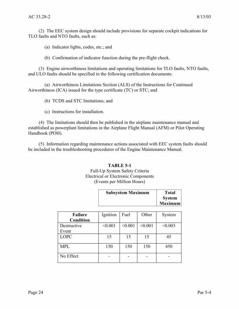
(1) EECSA Safety Criteria. This AC provides safety criteria, expressed in terms of events per million hours, that has been found acceptable for EEC systems installed on reciprocating engines. (a) The safety criteria is provided for each of the two major control subsystems (fuel and ignition), and also for any other subsystem. This is intended to accommodate varying degrees of system functionality by increasing the allowable failure event rates as subsystems or functions are added to the total system definition. However, once the total number of subsystems is defined and the associated maximum failure event rates are calculated, these failure rates are allocated across the total system and not to the individual subsystems. (b) Criteria is also provided for both full-up and degraded configurations. Criteria other than that presented in this AC may be appropriate if data is available that substantiates the alternative reliability objective. (c) The FAA consulted with industry representatives and analyzed available service data to establish the reciprocating engine control system failure event rates. This included a review of the FAA service difficulty reports (SDR) database, the National Transportation Safety Board (NTSB)/FAA accident database, and the Airplane Operators and Pilots Association (AOPA) accident data. SDR events relating to fuel system or ignition system failures were tabulated and corrected for known underreporting of events, and assumptions were made regarding the event data to estimate the actual rate. This reciprocating engine in-service data was then reviewed with reciprocating engine industry representatives and compared to the turbine requirement of one Loss of Thrust Control (LOTC) event per 100,000 hours. After an evaluation of the respective criticality of these two types of engines in their typical installations, the failure event rates of tables 5-1 and 5-2 were found to be consistent with FAA safety objectives for reciprocating engines. (2) Full-Up System Analysis Methods and Criteria. This analysis should be used to confirm that the full-up system meets the system safety criteria specified in table 5-1. The applicant should perform both a numerical FTA and an FMEA. An FMEA is a structured, inductive, bottom-up analysis used to evaluate the effects of each possible failure of the control system on engine operation. An FTA is a structured, deductive, top-down analysis used to identify the conditions, failures, and events that would cause each defined failure event. An FTA is a graphic method of identifying the logical relationship between each particular failure condition and the primary element or component failures, other events, or combinations of both that can cause the failure condition. (a) Mechanical components should be included in the structure of each of these analyses, but only to evaluate the interrelationships among the EEC system components. However, reliability values should not be assigned to the mechanical components, and they should not be included in the cumulative event rate for the system.
Page 22 Par 5-4

8/13/03 AC 33.28-2
(b) Table 5-1 provides safety criteria for the full-up system. Each of these system elements is additive; “other” applies to each subsystem in addition to the fuel and ignition systems. For example, an EEC system comprised of fuel, ignition, and wastegate control functions should meet a total system reliability of 15+15+15=45 LOPC events per million hours (and 450 MPL events per million hours). This criteria is then applied to the entire system and not allocated to each of the subsystems. Note that a maximum of 45 LOPC and 450 MPL events per million hours are allowed, regardless of the number of subsystems. For example, if the EEC system includes more than three subsystems, the sum of the LOPC rates for the total system should not exceed 45 LOPC or 450 MPL events per million hours for all of the electrical and electronic elements. (c) The event rates in table 5-1 should be applied to the highest appropriate system or subsystem level and not, for example, to individual components of the same system. (3) Degraded System Analysis Methods and Criteria. This analysis should be used to confirm that the system meets the system safety criteria stated in table 5-2 with an existing fault or faults in the system, when time limited operations with that fault or faults is desired. If the existing fault or faults does not affect engine operability and the criteria of table 5-2 are met, then Time-Limited Operations (TLO) may be approved for these fault conditions. The analysis determines the instantaneous failure rate with one or more failures in the system. A Markov analysis, or channel failure analysis for simple systems, may be used. d. TLO Implementation Requirements. FAA acceptance of the EECSA is based upon incorporating provisions in the EEC system design for the following: (1) All EEC system faults should be grouped into one of the following three operating limitation categories: (a) No Take-Off (NTO). Take-off is not acceptable for total system faults that result in calculated event rates that exceed the degraded system limits or when the system does not have sufficient resources to operate the engine properly. These system faults are defined as NTO faults. (b) TLO. Twenty hours of operation with total system faults is acceptable when the calculated event rates are greater than the full-up limits but less than the degraded system limits. These system faults are defined as TLO faults. In addition, the total system LOPC and MPL rates should not be greater than 450 and 4500 events per million flight hours, respectively, for the system to considered acceptable for TLO operations. (c) Unlimited Operation (ULO). Unlimited operation is acceptable when the calculated event rates are less than the full-up system analysis limits (this may apply to degraded system with certain minor faults). (d) The system limits are additive (from tables 5-1 and 5-2) for all subsystems included in the applicant’s EEC system design.
Par 5-4 Page 23
AC 33.28-2 8/13/03
(2) The EEC system design should include provisions for separate cockpit indications for TLO faults and NTO faults, such as: (a) Indicator lights, codes, etc.; and (b) Confirmation of indicator function during the pre-flight check. (3) Engine airworthiness limitations and operating limitations for TLO faults, NTO faults, and ULO faults should be specified in the following certification documents: (a) Airworthiness Limitations Section (ALS) of the Instructions for Continued Airworthiness (ICA) issued for the type certificate (TC) or STC; and (b) TCDS and STC limitations; and (c) Instructions for installation. (4) The limitations should then be published in the airplane maintenance manual and established as powerplant limitations in the Airplane Flight Manual (AFM) or Pilot Operating Handbook (POH). (5) Information regarding maintenance actions associated with EEC system faults should be included in the troubleshooting procedures of the Engine Maintenance Manual.
TABLE 5-1 Full-Up System Safety Criteria
Electrical or Electronic Components (Events per Million Hours)
Subsystem Maximum Total
System Maximum
Failure
Condition Ignition Fuel Other System
Destructive Event
<0.001 <0.001 <0.001 <0.003
LOPC 15 15 15 45
MPL 150 150 150 450
No Effect - - - -
Page 24 Par 5-4
8/13/03 AC 33.28-2
TABLE 5-2
Degraded System Safety Criteria Electrical or Electronic Components
(Events per Million Hours)
Subsystem Maximum Total System
Maximum
Failure Condition
Ignition Fuel Other System
Destructive Event
<0.001 <0.001 <0.001 <0.001
LOPC 150 150 150 450
MPL 1500 1500 1500 4500
No Effect - - - -
e. EECSA Qualitative Analyses. These analyses complement the quantitative analyses and substantiate that the applicant has evaluated all aspects of the EEC system design. These analyses should include the mechanical components as well as the electrical and electronic components. (1) Alternate Control Mode Analysis. Alternate or backup control modes or systems are usually necessary to meet the essentially single fault tolerant requirement of §33.28(c). However, unlike engines for transport category aircraft, the backup modes for reciprocating engines may have limited control authority. (a) If the alternate control mode does not affect engine operability, and if the predicted event rate of the control mode does not exceed the criteria of table 5-2, then 20 hours of operation is permitted in this mode. (b) The acceptability of these alternate systems should be based on the following factors: 1. Effect on engine operability; and 2. Characteristics of the transition to the alternate control mode.
Par 5-4 Page 25
AC 33.28-2 8/13/03
(c) Factors relating to engine operability that should be considered in the design and evaluation of any alternate operating mode(s) should include, but are not limited to, the following: 1. Maximum power level achievable in the alternate operating mode; 2. Engine control range in the alternate operating mode; 3. Altitude restart capability; 4. Dormant failures of the alternate operating mode, and documentation of any automatic or manual checks to ensure the availability of the mode; and 5. Throttle motion restriction or any other envelope restrictions. (2) Control Mode Transition Analysis. The EECSA should evaluate systems that use alternate control modes as backup systems, including fail-fixed or fail-to-manual control systems, to determine acceptability of the mode transfer mechanism. (a) A manually activated switch to transition to the alternate mode may be acceptable if the instruction manual documents this emergency procedure and it is evaluated in the EECSA. (b) In some turbine applications the FAA has accepted a “fail-fixed” fuel flow followed by a manually activated switch to the alternate mode. If this type of alternate control mode is incorporated in a reciprocating engine, the applicant should make provisions for indication of the “fail-fixed” condition to the flight crew. (c) The alternate mode may be implemented using hydromechanical, electrical/electronic, manual means, or any combination of these means. The engine instruction manual should state the power change associated with an automatic transfer to the alternate mode. (d) Power changes during automatic transfer to backup should be limited to less than 15%. Power changes greater than 15% may be accepted if they result from a crew-selected transfer. (e) Acceptable transition between all control modes should be demonstrated to the greatest extent possible. Development flight-testing should be used for further evaluation, if available. If pilot action is required in the fault detection and transfer of control, the engine instruction manual should declare the faults involved in such a situation and the aircraft certification program should evaluate the condition(s).
Page 26 Par 5-4
8/13/03 AC 33.28-2
(f) For transfers that occur automatically, the following factors should be considered: 1. The frequency of occurrence of transfers to any alternate control mode. Computed frequency of transfer to any alternate control mode should be supported with data from endurance or reliability testing, in-service experience on similar equipment, or other data acceptable to the FAA. 2. Faults that would result in transfer to any alternate mode, and the capability of detecting these faults. 3. Self-test coverage and diagnostics. Sufficient self-test coverage and diagnostics should be provided to allow detection of error conditions critical to system performance. 4. Time delays in the transfer of control. The engine installation manual should specify time delays in the transfer of control. In some cases, the certification engineer may not be able to determine if the mode transition provides a safe and acceptable system in accordance with part 33 based solely on analytical or simulation data. An engine test or flight test program could be used to provide additional data. In any case, such control transition delays may or may not be certifiable at the aircraft level depending on the installation. The aircraft certification program should fully evaluate any control mode transition. 5. Availability of the alternate mode. If the alternate mode is not exercised during normal mode operation, an inspection interval to uncover latent failures in the alternate mode components, or a procedure for exercising the alternate mode, should be specified to ensure that the alternate mode is functional and available. Any inspection interval or procedure requires FAA approval. This should be included in the Operating Instructions and in the Engine Maintenance Manual. 6. Provisions for signal(s) to indicate a mode transition. (g) Pilot workload and performance during transition to or operation in an alternate control mode may need evaluation at the aircraft level. The applicant should review the applicable aircraft certification requirements and coordinate with the installer, if known, to determine if any alternate operating modes would comply with the applicable aircraft requirements. These issues have been significant for some programs. (3) EEC System Output Data Analysis. The EECSA should include information about faults or failures that could cause the transmission of faulty or drifting engine parameters to the aircraft systems, including a prediction of the rate of occurrence. The following engine output parameters are examples of parameters that could be addressed in this analysis: (a) Oil pressure; (b) Engine speed; (c) Manifold pressure;
Par 5-4 Page 27

AC 33.28-2 8/13/03
(d) Cylinder head temperature; (e) Turbine inlet temperature; (f) Exhaust gas temperature; (g) Calculated engine power parameters (horsepower or torque, etc.); (h) Combustion pressure; and (i) Engine detonation (sometimes called knock). (4) Existing Subsystems Analysis. The EECSA should include an evaluation of the functional interaction of any existing mechanical control system elements that remain on the engine after incorporation of the EEC system or subsystem. The existing subsystems analysis should: (a) Address existing mechanical subsystems such as carburetors, magneto ignition, turbo mechanical wastegates, and mechanical fuel injection; (b) Substantiate interface and installation requirements related to these existing mechanical systems or components; and (c) Address effects on the EEC system of failures of these mechanical systems. (5) Local Events Analysis. When the installation environment is more severe than the declared environmental limits, the EECSA safety criteria does not apply. Occurrence of severe environmental events would normally be limited to one engine and are referred to as “local events.” A local event is not usually considered a common mode event; common mode threats, such as HIRF, lightning and rain are not considered local events. (There may be installations in which multiple engines are affected by the same local event. Such installations should be considered by the engine manufacturer and will be reviewed during aircraft certification.) (a) Examples of local events: 1. Fluid leaks or mechanical disruptions that could lead to damage to control system electrical harnesses, connectors, or the control unit(s); 2. Fires; and 3. Overheat conditions, for example, those resulting from hot air duct bursts.
Page 28 Par 5-4
8/13/03 AC 33.28-2
(b) Consideration of Local Events. 1. Whatever the local event, the resultant behavior of the EEC system should not cause a destructive event. 2. If accommodation of a particular local event is based on the assumption that there is another function that affords the necessary protection, it should be shown that this function is not rendered inoperative by the same local event on the engine (including destruction of wires, ducts, or power supplies). 3. For the purposes of this AC, an overheat condition exists when the temperature of the system components is greater than the maximum design operating temperature for the components, as declared by the engine manufacturer in the engine instructions for installation. The electronic portions of the control system should not cause a hazardous engine effect when the electronic components or units of the system are exposed to a continuous overheat or over-temperature condition. Specific design features or analysis methods should be used to show compliance with respect to the prevention of hazardous effects. When this is not possible, due to the variability or the complexity of the failure sequence, for example, the FAA may require testing. (c) Fire Testing. Exposure of the electrical and electronic parts of the EEC system to fire should not intensify the severity of the fire condition. If the EEC system is located in a fire zone, the applicant should perform either an analysis of system effects due to fire damage, or fire testing. Fire zones are defined in appropriate aircraft design regulations. 1. The fire requirements do not specify the length of time that electronic parts are required to function when exposed to fire. The FAA has developed an acceptance criteria for EEC systems that specifies either that the control system must maintain the ability to safely shut down the engine when exposed to fire, or that there must be an alternate method, such as a fuel shutoff valve, that allows the pilot to safely shutdown the engine when there is a fire in the engine compartment. In addition, the fire analysis or fire test should verify that when exposed to fire for a five minute period the system does not take unwanted action that could be hazardous to the aircraft. 2. The fuel handling parts of the EEC system, including the fuel injector valve parts that are directly in contact with the fuel, should comply with the requirements of §33.17, which requires these parts to be fire resistant and shielded or located to guard against the ignition of leaking flammable fluids. 3. The FAA has accepted computer simulations of EEC system exposure to fire instead of fire tests on production hardware as demonstration of compliance with fire requirements. The computer simulation should be validated by analysis or test, or both, and should be approved by the FAA. The FAA should also approve all assumptions upon which construction of the computer simulation is based.
Par 5-4 Page 29

AC 33.28-2 8/13/03
4. Hardware emulations for use in fire tests are also acceptable. Hardware emulations should be validated by analysis or test, or both, and should be approved by the FAA. (d) Probability of Local Events. There is no probability associated with the occurrence of local events. Therefore, all foreseeable local events should be considered. It is difficult to address all possible local events in the intended aircraft installation at the time of engine certification. Therefore, sound engineering judgement should be applied to identify the reasonably foreseeable local events. 1. Each wire interfacing with the electronic control unit should be tested or analyzed with respect to wiring faults. These faults should include opens and shorts to ground, and the test or analysis should show that the fault results in an identified and non-hazardous engine response. 2. Aircraft wiring that interfaces with the EEC system should be tested or analyzed for shorts to aircraft power. These “hot” shorts should result in an identified and non-hazardous effect. The engine instructions for installation should state the potential effects of wiring faults on aircraft interface wiring. The installer is responsible for ensuring that there are no wiring faults that could affect more than one engine, and if practical, more than one EEC system channel of a single engine by isolation and separation of the relevant wiring/conductors. 3. When the physical separation of conductors is not practical, the engine manufacturer and installer should coordinate with each other to ensure that the potential for common mode faults between engine controls is eliminated and that the potential for common mode faults between channels on one engine is minimized. (e) Fluid Susceptibility. The applicant should assess the effects of hydraulic or lubricating leaks impinging on components of the EEC system by analysis or test. These conditions should not result in a hazardous engine effect, nor should the fluids be allowed to impinge on circuitry or printed circuit boards and result in a potential latent failure condition. Refer to RTCA Document number DO-160D for test procedures for fluid susceptibility. (6) Guidance for Use of Commercial or Industrial Grade Electronic Parts. When the engine type design specifies commercial or industrial grade electronic components, the applicant should have the following data available for review, as applicable: (a) Reliability data that substantiates the failure rate for each component used in the EEC system reliability analysis and the EECSA for each commercial and industrial grade electrical component specified in the design. (b) The EEC system applicant’s procurement, quality assurance, and process control plans for the vendor-supplied commercial and industrial grade parts. These plans should ensure that the parts will be able to maintain the reliability level specified in the approved engine type design.
Page 30 Par 5-4
8/13/03 AC 33.28-2
(c) Unique databases for similar components obtained from different vendors, because commercial and industrial grade parts may not all be manufactured to the same accepted industry standard, such as military component standards. (d) Substantiation that the proposed extended range of the specified components is suitable for the application, if the declared installation temperature environment for the EEC system is greater than that specified by the manufacturer of the electronic components specified in the engine type design. Additionally, if commercial or industrial parts are used in an environment beyond their specified rating and cooling provisions are required in the design of the EEC system, the applicant should specify these provisions in the instructions for installation. Failure modes of the cooling provisions included in the EEC system design that cause these limits to be exceeded should be considered in determining the probability of failure. (e) Two recently published documents provide guidance on the application of commercial or industrial grade components: 1. IEC/PAS 62239, Electronic Component Management Plans, edition 1.0, dated April 2001. 2. IEC/PAS 62240, Use of Semiconductor Devices Outside Manufacturers’ Specified Temperature Ranges, edition 1.0, dated April 2001.
(7) Programmed Logic Devices. Due to the nature and complexity of systems containing digital logic, programmed logic devices should be developed using a structured development approach, equivalent to the hazard associated with failure or malfunction of the system in which the device is contained. Programmed logic devices include application specific integrated circuits (ASICs) and programmable logic devices (PLDs). (a) ASICs are defined as integrated circuits that are developed to implement a function, including, but not limited to: gate arrays, standard cell and full custom components encompassing linear, digital and mixed mode technologies. (b) A PLD is defined as any device that is purchased as an electronic part and altered to perform an application specific function. PLDs usually require programming by the equipment manufacturer. PLDs include, but are not limited to, the following: 1. Programmable array logic (PAL) devices; 2. Programmable logic array (PLA) devices; 3. General array logic (GAL) devices; 4. Field programmable gate array (FPGA) devices; and 5. Electrically or erasable programmable logic devices (EPLD).
Par 5-4 Page 31

AC 33.28-2 8/13/03
(c) RTCA Document DO-254 provides guidance for the criticality, failure condition categories, and design assurance levels associated with development of programmed logic devices. (d) For off-the-shelf equipment or modified equipment, service experience may be used to demonstrate compliance. This should be acceptable if the worst-case failure or malfunction of the device for the new installation is not more severe than that for the original installation of the same equipment on another application. The applicant should also consider significant differences related to the environmental or operational category of the aircraft in which the original system was installed and certified.
Page 32 Par 5-4

8/13/03 AC 33.28-2
CHAPTER 6. SECTION 33.28(d) 6-1. Rule Text. Section 33.28(d) provides that each EEC system must: “Have environmental limits, including transients caused by lightning strikes, specified in the instruction manual.” 6-2. Intent of Rule. Section 33.28(d) ensures that the environmental operating limitations of the EEC system are specified in the certification data as installation requirements for the installer. Section 33.28(d) complements §33.53, reciprocating engine component test, which requires the corresponding environmental testing used to establish the environmental limitations. Both §§33.28(d) and 33.53 encompass electrical environmental conditions such as lightning, HIRF, EMI, as well as physical environmental conditions such as temperature, humidity, vibration, and water. The applicant should substantiate the declared electrical environmental limitations by component and system tests of the EEC system. The engine endurance test of §33.49 provides some substantiation of the physical environmental conditions. However, for those physical environmental and installation conditions not simulated during the engine endurance test, the applicant should conduct tests or analyses to establish that both the individual components and the system will operate properly over the full range of these conditions. 6-3. Guidance. Although the FAA does not specify the test limits, the conditions declared by the applicant should represent environments that would be encountered in the engine installation. Due to the obvious overlap of §§33.28(d) and 33.53, this AC provides guidance for the tests used to establish the environmental limitations. This guidance provides a method, but not the only method, for demonstrating compliance with §33.28(d). See appendix 1 for a list of compliance documents that may be submitted for this section. 6-4. Electrical Environmental Limitations. Electrical environmental limitations include limitations for the effects of HIRF, lightning, and EMI. a. Declared Levels. (1) If the installation is known, the engine control system should be tested at levels that the engine and aircraft manufacturers have agreed upon. With this agreement, the installation should meet the aircraft certification requirements. Successful completion of the testing to the agreed-upon levels would be accepted for engine type certification. This, however, may limit the engine to a specific aircraft installation. (2) If the aircraft application is not known or defined at the time of the engine certification, the engine manufacturer may use the default values defined in this paragraph and use assumed installation attenuation effects. (a) HIRF Default Values. The FAA has established recommended minimum default levels for system laboratory HIRF tests: 1. For frequencies from 10 kHz to 700 MHz, the minimum test level should be 100 volts per meter average.
Par 6-1 Page 33

AC 33.28-2 8/13/03
2. For frequencies from 700 MHz to 18 GHz, the minimum test level should be 200 volts per meter average. (b) EMI and Lightning Default Values. AC 20-136 and RTCA Document DO-160 provide appropriate test values. b. Test Procedures. (1) General. The installed engine controls system, including representative engine-aircraft interface cables, should be the basis for certification testing. (a) EMI. EMI tests procedures and test levels should follow the guidelines of RTCA Document DO-160, MIL-STD-461, or MIL-STD-462. However, the applicant should provide the rationale for conducting a test using the MIL-STD-461 or MIL-STD-462 procedure if that test procedure differs from the corresponding RTCA Document DO-160D procedure. (b) HIRF. The applicant should use the HIRF test guidelines provided in Section 20 of RTCA Document DO-160D, or the equivalent. However, the tests defined in RTCA Document DO-160D apply to a component test level, requiring the applicant to adapt these test procedures to a system level HIRF test to meet the intent of §33.28(d). (c) Lightning. Lightning tests should follow the guidelines provided in AC 20-136 and Section 22 of RTCA Document DO-160D. Pin injection tests (PIT) should be conducted on the EEC unit and other system components as required. PIT levels should be appropriately selected from the tables of Section 22 of RTCA Document DO-160D. Environmental tests that follow the guidelines of MIL-STD-810E may be accepted instead of RTCA Document DO-160 tests if the MIL-STD-810E tests are equal to or more rigorous than those defined in RTCA Document DO-160D. (2) Open Loop Versus Closed Loop Testing. (a) HIRF, lightning, and EMI tests should be conducted as system tests on closed loop or open loop laboratory set-ups. The applicant should provide the closed loop set-up with the necessary mechanical means to actuate any system mechanical components to close the inner actuating loops. The applicant may use a simplified engine simulation to close the outer engine loop. Testing should be conducted with the engine control system controlling at the most sensitive operating point, as selected by the applicant. The system should be exposed to the HIRF, lightning, and EMI environmental threats while operating at the selected condition. The HIRF, lightning, and EMI environmental threats may have different operating points.
Page 34 Par 6-4

8/13/03 AC 33.28-2
(b) If the applicant conducts tests in open loop set-ups, the following factors should be considered: 1. If special EEC system test software is used, that software should be developed and implemented by guidelines defined for software levels of at least Level C in RTCA Document DO-178B, or the equivalent. In some cases, the application code should be modified to include the required test code features. 2. The system test set-up should be instrumented to monitor both the output drive signals and the input signals. 3. Anomalies observed on inputs or outputs should be duplicated on the engine simulation to determine if the resulting power or thrust perturbations comply with the pass/fail criteria. c. Pass/Fail Criteria. (1) HIRF and Lightning. The control system operation should not experience any adverse effects when exposed to the conditions of the HIRF and lightning tests. The following are considered adverse effects: (a) A greater than +/-10% change of rated power or thrust change from the normal control governing capability for a period of more than one second; (b) Component damage; (c) False fault annunciation to the crew that continues beyond the duration of the HIRF or lightning event and could cause unnecessary or inappropriate crew action; and (d) Erroneous operation of engine protection circuits. (2) EMI. RTCA Document DO-160D provides pass criteria for EMI testing. d. Component and Software Design Changes. Hardware or software design changes implemented after initial qualification should be evaluated for their effects on the EMI and HIRF and lightning environment. Appropriate testing or analysis, or both, should be defined to ensure that the original basis for certification is maintained. The applicant should conduct component level testing for these purposes. e. Maintenance Requirements. Section 33.4 and appendix A to part 33 require that the applicant prepare ICA for all engine parts to ensure the continued airworthiness of the installed systems. AC 33.4-1, “Instructions for Continued Airworthiness,” provides guidance for preparation of ICAs. These instructions should include maintenance requirements for the electrical environment protection features because these features depend, to some extent, on the physical integrity of the design. The maintenance requirements for HIRF protection features to
Par 6-4 Page 35

AC 33.28-2 8/13/03
be considered during certification include periodic inspections or tests for required structural shielding, wire shields, connectors, and equipment protection components. The applicant must provide the engineering validation and substantiation of these maintenance requirements. Paragraph 7 of AC 20-136, “Maintenance and Surveillance,” provides additional guidance for continued airworthiness of system lightning protection features. 6-5. Physical Environmental Limitations. Physical environmental limitations include limitations for the effects of physical environmental factors such as temperature, humidity, vibration, and water. The applicant should substantiate all components of the EEC system, including all electronic units, sensors, harnesses, hydromechanical components, electromechanical components, and any other associated components, for proper operation over the full range of physical environmental conditions. For those components that undergo testing, the environmental limiting conditions should be simulated in a laboratory test fixture. If possible, the complete engine should be tested. a. Environmental test requirements are specified in RTCA Document DO-160 and listed in table 6-1. Acceptable test procedures for each item are referenced in the same table. Not all tests are applicable to all components. The applicant should provide rationale for the selection of applicable tests for each component. b. Use of the pre-established environmental classifications of RTCA Document DO-160 allows certification of components in a consistent manner, independently from installation considerations. However, the classification specified by the applicant should represent the environment of the proposed installation. c. The applicant should prepare an environmental test plan, summarized in an environmental test matrix, that defines the method to be used to qualify the component for each of the environments. The applicant should submit the plan and test matrix to the FAA for review and approval before testing is initiated. Generally, the applicant should test only the types of environments that the components are expected to encounter. The matrix should note other environments as “not applicable.” The components may be qualified by test, similarity, analysis, and combinations of these factors. For substantiation by similarity, the component should be shown to be sufficiently similar and to operate in an environment that is the same or less severe than the previously certified component. d. Before the testing is initiated, all conformity requirements for the software, hardware, and the test setups should be established and approved by the FAA. Conformity should be documented as part of the Certification Report. The applicant should reconcile any differences between the test hardware and the type design hardware in the test plan and submit it for FAA approval before the start of testing. e. The list of applicable requirements and associated tests or procedures (or their equivalent) in table 6-1 has been accepted for evaluating component airworthiness. The applicant should obtain FAA approval of these environmental test plans before initiating the tests.
Page 36 Par 6-4

8/13/03 AC 33.28-2
TABLE 6-1 ENVIRONMENTAL
CONDITIONS ACCEPTABLE TESTS/PROCEDURES
1 High Temperature Demonstration
RTCA Document DO-160, section 4 or MIL-STD-5007D paragraph 4.6.2.2.5
2 Low Temperature Demonstration
RTCA Document DO-160, section 4 or MIL-STD-5007D paragraph 4.6.2.2.7
3 Room Temperature Demonstration
RTCA Document DO-160, section 4 or MIL-STD-5007D paragraph 4.6.2.2.6
4 Contaminated Fluids Reference §§33.35, 33.39 for fuel/oil/air requirements or MIL-STD-5007D paragraph 4.6.2.2.6 (fuel test only)
5 Vibration RTCA Document DO-160, Section 8 6 Impact RTCA Document DO-160, Section 7 7 Sustained Acceleration RTCA Document DO-160, Section 7
or MIL-STD-810E, Method 513 8 Sand and Dust RTCA Document DO-160, Section 12,
Category D or MIL-STD-810E
9 Fluid Susceptibility RTCA Document DO-160, Section 11, Category F
10 Salt Spray RTCA Document DO-160, Section 14, Category S or MIL-STD-810E
11 Induction Icing Reference §33.35 12 Fungus RTCA Document DO-160, Section 13,
Category F 13 Temperature and Altitude RTCA Document DO-160, Section 4 14 Thermal Cycle RTCA Document DO-160, Section 5 15 Explosion Proofness RTCA Document DO-160, Section 9 16 Humidity RTCA Document DO-160, Section 6
or MIL-STD-810E 17 Waterproofness RTCA Document DO-160, Section 10
MIL-STD-810E (RAIN) 18 Power Input RTCA Document DO-160,
Sections 16 and 17 or MIL-STD-704
Par 6-5 Page 37 (and 38)


8/13/03 AC 33.28-2
CHAPTER 7. SECTION 33.28(e) 7-1. Rule Text. Section 33.28(e) provides that each EEC system must: “Have all associated software designed and implemented to prevent errors that would result in an unacceptable loss of power or thrust, or other unsafe condition, and have the method used to design and implement the software approved by the Administrator.” 7-2. Intent of Rule. Section 33.28(e) requires that EEC system software undergo a sufficient level of design assurance testing to ensure, with a high level of confidence, that errors in the software are prevented, and requires that the FAA approve the method used to design and implement the software. 7-3. Guidance. The following guidance provides a method, but not the only method, for demonstrating compliance with §33.28(e). Compliance with §33.28(e) should be demonstrated by software design and implementation in accordance with an approved method, such as RTCA Document DO-178B, in combination with system validation testing. a. Compliance Elements. (1) Software Design and Implementation Process. RTCA Document DO-178B, “Software Considerations in Airborne Systems and Equipment Certification,” provides guidelines for the software design and implementation process. This process includes the following activities: (a) Life cycle definition; (b) Planning; (c) Development; (d) Software verification; 1. Requirements-based coverage analysis should be conducted to demonstrate that the system requirements allocated to the software have been properly implemented. 2. The software should be verified by open or closed loop bench testing on a system that provides an electrical simulation of the engine system. (e) Configuration management; and (f) Quality assurance. (2) System Validation Testing. Validation testing should be conducted to substantiate successful integration of the EEC system software and the engine control system. Validation testing should be performed on a complete engine, or on a test rig that provides a physical simulation of the engine control system.
Par 7-1 Page 39

AC 33.28-2 8/13/03
b. Software Level Requirement. The level of confidence regarding error prevention in the software is directly related to the scope of the design assurance activity. These design assurance scopes have been defined in terms of software levels. These levels have been correlated to EEC system functional criticality. The FAA has accepted EEC system software verification to software levels defined in RTCA Document DO-178B as substantiation for the error prevention requirement. The following information is provided for determining the software level: (1) RTCA Document DO-178B software level C has been determined to be the minimum requirement for the reciprocating engine EEC systems to which this AC applies. Level C would be acceptable for single-engine or twin-engine airplanes under 6000 pounds maximum take-off weight (MTOW) approved under part 23 normal, utility or acrobatic categories, or similar CAR 3 approval. (2) The guidance provided in this AC does not apply to reciprocating EEC systems installed in airplanes approved under part 23 commuter or part 25 transport categories. Therefore, the minimum software level for those EEC systems should be determined by performing an airplane system-level safety analysis. (3) For reciprocating EEC systems installed in any other aircraft, the applicant should evaluate the failure condition criticality of EEC system functions to determine if Level C software would be adequate. This would require coordination with the aircraft designer and the cognizant aircraft ACO during the EEC system development program. c. Software Partitioning. Non-critical software may be partitioned from the critical software, allowing the non-critical software to be designed and implemented at a lower level than that established for the critical software. (1) The applicant should substantiate the adequacy of the partitioning method. (2) The partition should be developed to the highest level of the components being partitioned. (3) The applicant should consider if the lower levels of the partitioned software are appropriate for the anticipated installations. If the criticality level requirement were higher in subsequent applications, it would be difficult to raise the software level without repeating the software life cycle processes for the new level. d. Software Integrity. RTCA Document DO-178B provides guidance for assurance of software used at specified hazard levels. As with all guidance to which this document refers, DO-178B may be modified or updated due to events or advancements in technology.
Page 40 Par 7-3

8/13/03 AC 33.28-2
CHAPTER 8. INTEGRATION OF ENGINE, PROPELLER, AND AIRCRAFT SYSTEMS
8-1. EEC System Integration Certification Plan (SICP). There must be a clear definition of the respective certification tasks of the various applicants: engine, propeller, and aircraft manufacturers, with the associated engine, propeller, and aircraft certification authorities. This should be documented in an EEC SICP, submitted by the applicant for engine certification. The plan should be included as an appendix to the instructions for installation and should include the following: a. Distribution of Compliance Tasks. The tasks for the certification of the aircraft propulsion system equipped with electronic controls may be shared between the engine, propeller, and aircraft manufacturers. The distribution of these tasks between the manufacturers should be identified and agreed on by the appropriate engine, propeller, and aircraft authorities. The EEC SICP should summarize the engine applicant’s responsibilities for these certification tasks. The plan should list each task related to the EEC system certification and define those for which the engine applicant is responsible and those for which the aircraft or propeller applicant is responsible. The plan should address all analyses and tests required for EEC system certification. b. Interface Definition and Other Data. The EEC SICP should include interface definitions and other data for the functional, hardware, and software aspects that have been integrated between the engine, propeller, and aircraft systems. The plan should describe integration aspects or provide cross-references to the instructions for installation for the following items: (1) Functional requirements; (2) Fault accommodation strategies; (3) Maintenance strategies; (4) Software quality level (per function if necessary); (5) The reliability objectives for: (a) LOPC and MPL events; and (b) Transmission of faulty parameters. (6) The environmental requirements, including the degree of protection against lightning or other electromagnetic effects (for example, the level of induced voltages that can be supported at the interfaces); (7) Engine, propeller, and aircraft interface data and characteristics; and (8) Aircraft electrical power supply requirements and characteristics (if relevant).
Par 8-1 Page 41

AC 33.28-2 8/13/03
c. Design Change Control. The EEC SICP should describe the design change control system established to support post-certification activity. This system should ensure that changes to any control element that is integrated into the EEC system are evaluated by all design approval holders of that integrated system. 8-2. Aircraft Functions Integrated into the Engine Control System. a. Integration Activities. These activities involve the integration of aircraft and propeller control functions (that is, those that have traditionally not been considered engine control functions) into the EEC system’s hardware and software. Examples include: propeller speed governors, which govern speed by varying pitch, cowl flap controls, and automatic throttle systems. (1) The EEC system may be configured to contain only part of the aircraft system’s functions, or it may contain all of it. Turbine engine thrust reverser control systems are an example in which only part of the functions are included in the EEC system. In such cases, the aircraft is configured to have separate switches and logic (that is, independent from the EEC system) as part of the thrust reverser control system. This separation of reverser control system elements and logic provides an architectural means to limit the criticality of the functions provided by the EEC system. (2) However, in some cases the EEC system may be configured to incorporate virtually all of a critical aircraft function. Examples of this are EEC systems that contain full authority to govern propeller speed and automatic throttle systems in turbofan-powered aircraft. The first of these is considered critical because if an engine fails, the logic in the engine control must be configured to feather the propeller on that engine. Failure to rapidly feather the propeller following an engine failure results in excessive drag on the aircraft; such a condition can be critical to the aircraft. Automatic throttle systems are considered critical because the system is required to react to an engine failure during take-off by increasing the thrust of the remaining functioning engine(s); the increased thrust on the functioning engines is necessary to achieve the required aircraft performance. b. Certification Considerations. (1) Engine Certification. The engine certification program should include all hardware and software substantiation requirements for the hardware and software that resides on the engine, including those that provide aircraft or propeller functions. This includes environmental testing of all components and software quality assurance of the software that performs both the engine and aircraft functions. (a) The EECSA and other analyses (aircraft power, fault accommodation, etc.) that the engine applicant should submit for engine certification should address only engine functions performed by the EEC system. The aircraft and propeller functions do not need to be evaluated in the EECSA unless they affect engine operation or reliability.
Page 42 Par 8-1

8/13/03 AC 33.28-2
(b) The engine applicant should include in the instructions for installation the architecture, failure event rate data, and any other requirements for the aircraft or propeller functions that reside in the EEC system components. This data is then considered part of the engine type design to which the associated aircraft or propeller certification program must adhere. (2) Aircraft or Propeller Certification. (a) The aircraft or propeller certification programs should use the data in the engine instructions for installation for input into the aircraft or propeller safety analysis for evaluation of the safety and functional aspects of those systems. (b) The aircraft or propeller functions performed by the EEC system should be substantiated by test and analysis during the airplane or propeller certification program. 8-3. Integration of Engine Control Functions into Aircraft Systems. a. Integration Activities. The trend toward systems integration may lead to aircraft systems performing functions that are traditionally considered part of the engine control. (1) Limited authority functions that are not required by the EEC system for engine control may be incorporated into the aircraft or propeller systems. This type of function would augment the basic engine control with inputs based on certain aircraft flight conditions. In these cases, the EEC system would provide all the functions required to safely operate the engine in accordance with part 33. An example of such a limited authority function is an engine control that receives a torque output demand signal from the aircraft and responds by changing the engine’s fuel flow and other variables to meet that demand. (2) Other designs may use aircraft systems to implement a significant number of the engine control system functions. Examples of this are the complex integrated flight and engine control systems for tiltrotor aircraft. These systems are integrated into aircraft avionics units and govern engine speed, rotor speed, rotor pitch angle, and rotor tilt angle. b. Certification Considerations. (1) Engine Certification. (a) The EECSA and other analyses (loss of aircraft power, fault accommodation, etc.) submitted for engine certification should include the engine control functions performed by the aircraft or propeller system. The engine applicant should substantiate the adequacy of the event failure rates, function architectures, and any other requirements used in these analyses by test and analysis. The analyses may be based on actual or assumed aircraft or propeller systems design characteristics.
Par 8-2 Page 43
AC 33.28-2 8/13/03
(b) The engine applicant should include in the instructions for installation the architecture, failure event rate data, and any other requirements for the engine functions that reside in the aircraft or propeller system components. This data is then considered part of the engine type design to which the associated aircraft or propeller certification program must adhere. (2) Aircraft or Propeller Certification. (a) The data submitted for the aircraft or propeller certification program should substantiate that the associated aircraft or propeller system meets these engine installation requirements. (b) The aircraft or propeller certification program should include all hardware and software substantiation requirements for the hardware and software that resides on the aircraft or propeller, including those that perform engine control functions. This includes environmental testing of all components and software quality assurance of the software that performs both the engine and airplane functions.
Page 44 Par 8-3

8/13/03 AC 33.28-2 Appendix 1
APPENDIX 1. CERTIFICATION COMPLIANCE DOCUMENTS The following is a representative summary of documents that an applicant may submit to show compliance to §33.28. Specific reciprocating engine EEC system certification programs may vary; not all documents in this list will apply to all programs.
Submitted Document Major Sections AC Chapter
Reference
14 CFR §
Instruction Manual • Description • Installation • Operation
3 33.28(a)
Certification Data Interface Manual (CDID)
• Failure of Aircraft Power Analysis • Failure of Aircraft Data Analysis • EECSA Assumptions • EECSA Results • Environmental Testing • Software Validation and Verification
3 33.28(a)
Aircraft-Supplied Power Analysis
4 33.28(b)
Aircraft-Supplied Data Analysis 4 33.28(b) EECSA Assumptions 5 33.28(c) EECSA Quantitative Analysis • Full-up System
• Degraded System 5 33.28(c)
EECSA Qualitative Analysis • Alternate Control Mode Analysis • Control Mode Transition • EEC System Output Data Analysis • Existing Subsystems Analysis • Local Events Analysis • Commercial or Industrial
Grade Electronic Parts Analysis • Programmed Logic Devices Analysis
5 33.28(c)
Declared Component/System Environmental Limits
• Electrical • Physical
6 33.28(d)
Component/System Environmental Test Plans and Test Reports (Electrical)
• HIRF • Lightning • EMI
6 33.53 33.28(d)
Page 1

AC 33.28-2 8/13/03 Appendix 1
Submitted Document Major Sections AC Chapter
Reference
14 CFR §
Component/System Environmental Test Plans and Test Reports (Physical)
• High/Low/Room Temperature Demonstrations
• Contaminated Fluids Vibration • Impact • Sustained Acceleration • Sand and Dust • Fluid Susceptibility • Salt Spray • Induction Icing • Fungus • Temperature and Altitude • Thermal Cycle • Explosion Proofness • Humidity • Waterproofness • Power Input
6 33.53 33.28(d)
Plan for Software Aspects of Certification (ref. RTCA DO-178B)
7 33.28(e)
Software Configuration Index (ref. RTCA DO-178B)
7 33.28(e)
Software Accomplishment Summary (ref. RTCA DO-178B)
7 33.28(e)
NOTE: Applicants should prepare all remaining Software Design Assurance documents in accordance with RTCA DO-178B and have them on file and available for FAA audit.
EEC System Integration Certification Plan (SICP) (if applicable)
• Distribution of Compliance Tasks • Interface Definition & Other Data • Design Change Control
8 33.28
Page 2