dr. stephen r. borneman, ph.d., aerospace engineering ... · mechanical shock is fundamentally...
TRANSCRIPT

Geometrical Considerations Involved in Hydrodynamic Shock Efficiency
Dr. Stephen R. Borneman, Ph.D., Aerospace Engineering
Curtiss-Wright - INDAL Technologies, Mississauga, Ontario, Canada
Abstract
In recent years, navies around the world are designing lighter, faster and more powerful
underwater crafts; however, equipment installed on these crafts has not kept pace. At Indal
Technologies, towed array/cable handling equipment is designed such that it is optimized for
hydrodynamic and mechanical shock based on both cost and weight. To achieve this feat, a good
understanding of both types of underwater shocks is important (hydrodynamic & mechanical).
Obviously equipment subject to shock, mounted on submarines, must be designed based on
given specifications such as (US, British, European and Canadian). However, by considering
concepts such as wave diffraction, surface pressure dynamics and shock transparency, equipment
weight and corresponding costs can be considerably reduced while designs remain robust and
shock compliant. In this paper, a geometrical review of ship mounted equipment with respect to
underwater explosions is presented and a description of how weight reduction is achieved using
explosion dynamics.
Introduction
Navies around the world are moving to lighter, faster ships with the advent of new
analysis techniques and highly accurate simulations most of which are validated by experimental
tests. These lighter ships provide better maneuvering, reduced fuel consumption and availability
for greater payload. While navies are moving to lighter materials and equipment optimized for
strength, performance and weight, the explosive resistance of these ships is still maintained at the
highest standard. This triumph is achieved by increasing understanding of ship dynamics in the
sea and environmental mechanical and hydrodynamic shock transient dynamics.
Submarines and surface ships are persistently incorporating new advanced combinations of
materials to achieve these lighter structures and robust designs, including the implementation
laminated composite structures. In the past decade, ship and submarine builders have been
actively using lighter materials for their advanced physical properties; however, the naval
equipment suppliers have not kept pace. At Indal, lightweight materials and corresponding
analysis techniques are continually advancing with the industry to provide towed array handling
systems that are optimal for either ship or submarine environments.
Indal Technologies has unique experiences working with various navies around the world, with a
wide understanding of a variety of specifications and codes, the development of custom sonar
cable handling equipment accomplished. The company also provides aircraft handling equipment
and detailed ship/aircraft interface dynamics, merging both naval and aircraft industries.
Assuredly, the aircraft industry requires light designs as it directly impacts range and payload
during flight operations. Accordingly, this knowledge and experience is extended to designing
naval equipment. However, the environmental conditions between aircraft and naval ships are
significantly different, lighter and more efficient designs are always investigated and
implemented as a standard practice. Hydrodynamic/mechanical shock for submerged equipment
must also be considered in the design of sonar handling equipment.
This paper reviews underwater explosion dynamics and geometric considerations involved in
preparing the most optimized naval equipment designs. To achieve an explosion resistant design,
both mechanical shock and hydrodynamic shock must be considered for equipment submersed in
water. Mechanical shock is fundamentally transient dynamic movement of a surface ship or
submarine foundation that imparts a base excitation to mounted equipment. In contrast,
hydrodynamic shock is a transient pressure wave propagating in water at the speed of sound,
which diffracts around objects generating a differential pressure. As it pertains to submerged
equipment mounted to a submarine, the hydrodynamic shock load path is much different than
mechanical shock. Hydrodynamic shock waves diffract around objects and transmit shock wave
energy to the exposed surfaces, where, in turn, the shock load travels to the base where mounted
to the submarine. This means hydrodynamic shock energy can be controlled by surface geometry
characteristics, whereas, mechanical shock is mainly influenced by inertia, stiffness and fluid
damping. This paper will focus on the optimization of equipment that is subject to hydrodynamic
shock.
Selecting a shock mount to reduce the shock accelerations based only on tabulated stiffness's is
not always appropriate. This is especially true if the surrounding structure can be considered
light and flexible, and with complex anisotropic material coupling behavior, as many
shipbuilders are going towards, or if the equipment is mounted on flexible mounts where a large
number of characteristic modes of the equipment become crucial. With the power of transient
dynamic programs (i.e. ANSYS® or MSC NASTRAN), the dynamics of shock mounted
equipment is imperative in understanding the full rigid and flexible motions of a structural and
mechanical system. Understanding of transient dynamics, natural modal behavior, and
equipment response to unbalanced shock impulses, is fundamental in optimizing equipment and
structures aboard a submarine. Mass, stiffness, damping, surface area, wave diffraction, back
pressure time differentials and material anisotropy play significant roles in the hydrodynamic
transient response of naval equipment.
At Indal, one of the key aspects of hydrodynamic optimization is based on the normal surface
area and corresponding frontal and back pressures exposed to the shock wave. It is important to
recognize this frontal and back pressure and how it changes with the underwater shock wave.
Intuitively, in the static sense, the more surface area exposed to a shock wave, the greater the
overall unbalanced load generated on the equipment or structure. This is not always true. The
unbalanced load experienced by particular equipment exposed to shock is dependent on the
difference between the frontal pressure and back pressure over time. Back pressure rise time is
controlled by the nature of the geometry and wave diffraction. Therefore, a hydrodynamic shock
wave, moving the speed of sound in sea water, can be manipulated by the equipment geometry
and the net pressure on the structure can ultimately be reduced. The time between when a wave
impacts the front surface of an object, to when the supporting pressure on the back surface
builds, is essential in quantifying the magnitude of the unbalanced load. As a result, “time” plays
a major role when evaluating equipment responses to hydrodynamic shock.

Review of Explosion Dynamics and Wave Propagation
The process for which the detonation of an underwater explosion produces dangerous
shock waves is reviewed. An explosive first generates a superheated gas bubble with its
corresponding shock-wave travelling much faster than the speed of sound. The shock-wave then
reduces quickly to the speed of sound in water, while radially propagating outwards. Underwater
explosions can be extremely damaging to surface ships, submarines and onboard equipment,
however, the extent of that damage is first evaluated by determining the proximity of the
explosion, commonly referred to as the standoff distance, and weight of equivalent TNT. This
3D radial shock wave expansion can be idealized as a planar wave to facilitate peak pressure and
pressure decay calculations. The free field wave pressure from a blast can be quantified over
time by the following equation [1, 2],
t
w ePtP
0 (1)
The peak over pressure, 0P , for an underwater explosion decays exponentially over time and
quantified by the following relationship,
MPaR
WP
4.520 (2)
Where 0P is the peak over pressure, and are 0.33 and 1.13 for purposes of this paper and
previously used in [2, 3] and wP , is the free field wave pressure from the blast. Alpha and beta
constants are generally restricted and change for different shock specifications. In general, the
peak overpressure for an air blast is comparable to atmospheric pressure, conversely, for an
underwater blast; the peak over pressure is much greater than the hydrostatic pressure by several
orders of magnitude. For this reason, the hydrostatic pressure is negligible and ignored. is the
time constant and controls the pressure decay. W, denotes the equivalent weight of TNT and R
denotes the standoff distance.
From reference [3], the time constant is defined as,
22.0
3
1
3
1
6105.96
R
WW (3)
The initial shock wave generated by an underwater explosive charge is likely to reflect off the
sea bed. This reflected wave then merges with the initial radial wave, forming a super crest,
essentially doubling the wave amplitude (see Figure 1). Subsequently, the peak over pressure P0,
is multiplied by a factor of 2. If we consider simple plate type geometry, as the shock wave
strikes the plate, the amount of energy absorbed is dependent on the surrounding environment
and plate dimensions. The incident reflected pressure on the front face of the plate then linearly
decreases to the peak over pressure [4], 0P , such that,

f
ft
tPtP 201
, for ftt (4)
ftt
f ePtP
02, for
U
St
3 (5)
Where, fP , is a two stage equation for the pressure on the front face of a plate and ft (equal to
3S/U) is the time required for the reflected pressure to decay to the 0P .
Figure 1: Illustration of shock reflection off sea bed
Shock severity is usually described using a Hull Shock Factor (HSF). This represents the
available energy that may be absorbed by the hull from a shock wave. This hull acceleration
generates the mechanical shock at the foundation where equipment is installed. The excess
energy not absorbed, where the wave passes through the water backed hull plating, is available to
strike submerged equipment. A hull shock factor equation is found in [5], with the value of n
(restricted value), and not discussed further.
A water backed plate exposed to an underwater shock wave absorbs less energy than an air
backed plate. This is due to the fact that water backed plates have the capability to generate quick
back pressure balancing the initial front pressure. The following equation governs the motion of
a plate submerged in water,
AtPkxdt
dxc
dt
xdm n
2
2
(6)
Where, m represents the mass of the plate plus any added mass, c represents the damping of the
plate and, k is the structural stiffness of the plate in the load direction. The time varying net
pressure denoted, Pn(t) is derived based on the differential pressure of the front and back faces
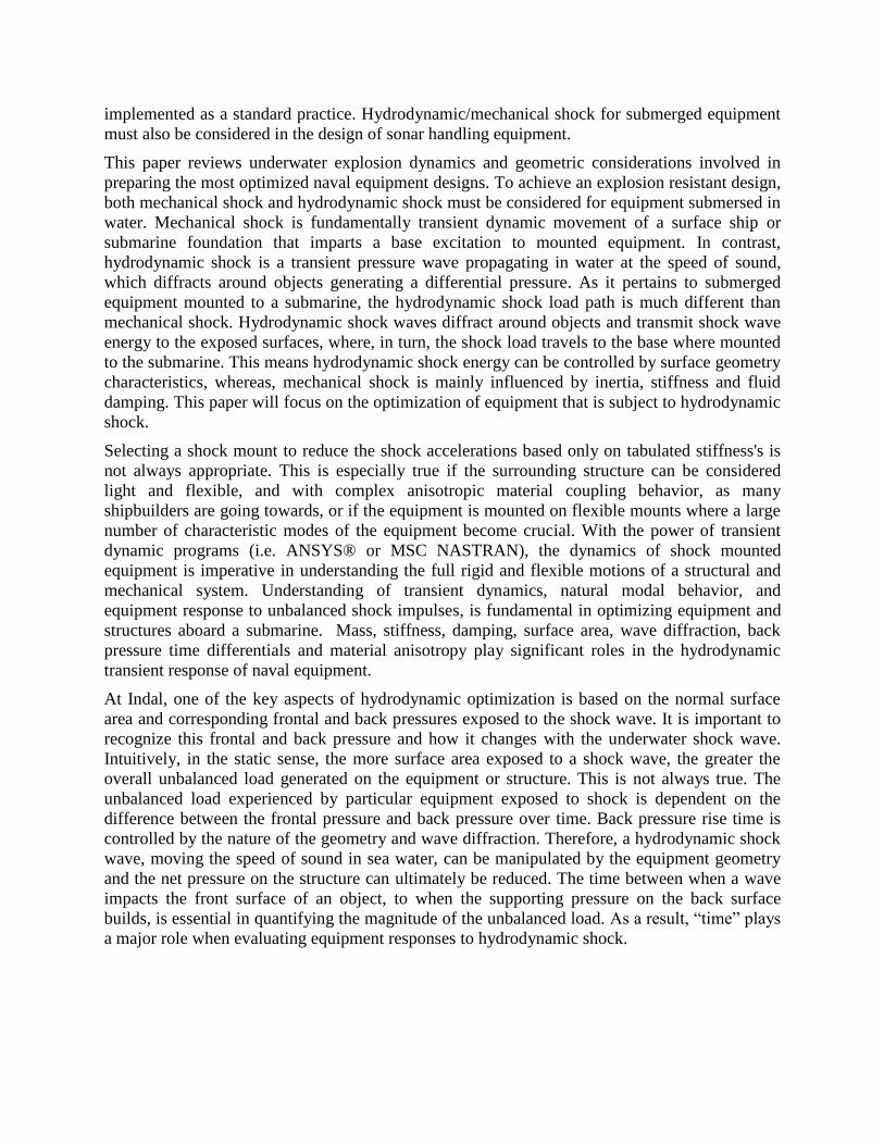
(see Figure 2a. In Figure 2b), the pressure Pr (reflected pressure) is equivalent to two times the
incident overpressure denoted, P0. According to reference [4], the reflected pressure reduces
linearly to the incident overpressure in 3S/U, and then continues to decay according to the
relationship presented in equation 2. Where S is the either the width or height of the plate
(whichever is shortest) and U is the speed of sound in water. The front plate pressure over time is
shown in Figure 2a. Pressure on the back surface of the plate begins to build after L/U to a peak
back pressure, pb, at a time of (L+4S)/U and is presented in Figure 2b.
(a) (b)
Figure 2: Hydrodynamic shock pressure; (a) front plate pressure, (b) back plate pressure
The overall unbalanced load generated from a shock wave can be evaluated by subtracting the
areas under curves, Figure 2a and Figure 2b. This unbalanced net pressure Pn(t) can then be used
in a subsequent calculations or dynamic simulations. The front pressure on the plate is solely
based on the incident shock wave and wave reflection; however, the back pressure is influenced
greatly based on the geometry of the plate. For example, consider a simple block in Figure 3.
Two main factors affect the back pressure and how it develops over time, specifically, the time
delay due to the distance (or thickness) required for the shock wave to reach the rear of the block
and the wave diffraction around the block (see Figure 4). When a shock wave strikes the front
surface of an arbitrary object, initial pressure is instantly high on the front surface. Next, the
wave traverses along the block further, and a balanced pressure is formed on each side, while the
front face pressure exponentially decays. Subsequently, as the wave reaches the back surface of
the block in L/U seconds, backpressure begins to build over an additional 4S/U. For this
example, S is equal to the shortest dimension, h (see Figure 3). For thin plates, where L<<S, the
back pressure begins to rise almost immediately after the front face is struck by the shock wave.
As a result, the net pressure depends mainly on the shortest dimension describing the area normal
to the wave. Conversely, if the plate is thickened into a block, with a length L>>S, the net
pressure depends mainly on the time taken for the wave to reach the back of the plate.
Intuitively, thin plates, with small values of b or h are ideal for optimizing equipment for mass
when exposed to hydrodynamic shock.

Figure 3: Square block geometry
Figure 4: Wave diffraction around a solid object
Hydrodynamic mass (added mass)
For objects moving in a dense fluid, such as water, additional mass referred to as “added
mass” or “hydrodynamic mass” must be accounted in any dynamic simulation or basic
calculations. The natural vibration of a structure or equipment mounted on flexible mounts is
equal to the root of the ratio of stiffness and mass. When vibrating in a dense fluid medium, such
as water, the structure or equipment can be thought of as carrying additional mass based on the
displaced fluid. In general, there is a threshold that should be considered when deciding on
incorporating added mass into calculations and simulations of submerged equipment. Added
mass should be ignored for systems that are considered rigid (i.e. Hzf 160 ). Added mass varies
depending on the geometry, much like aerodynamic drag. For a flat plate, the added mass per
unit length is evaluated as follows (see [6]),
bamh
2 (7)
Where a2 is the shortest dimension describing the area normal to the motion of the plate, and
b , is the span of the plate.
Shock Transparency
Shock transparency is a concept studied by researchers for many years, two of which are;
Huang [7] in 1979 and more recently Iakovlev [8] in 2007. Shock response of fluid filled
cylindrical shells has had a large impact on the design of double hull submarines and
advancement of multi-layered shell structures. The study of Iakovlev [8] led to a relationship
between the thickness and radius of a cylindrical shell with the shock transparency of the
cylinder. Unlike a flat plate, where the diffraction of a shock wave is most significant in

determining load transmitted to the plate, a fluid filled cylinder is greatly affected by the acoustic
waves generated inside.
f
s
r
h
0
0 (8)
Where, according to [7, 8], is the dimensionless mass per unit area of the shell, h0 is the
thickness of the shell, s is the density of the shell, f the density of the fluid, and ro is the
radius of the shell. This relationship is very important in hydrodynamic shock efficiency, by
lowering the thickness and increasing the radius of a cylinder; the more transparent the geometry
is to hydrodynamic shock. Therefore, optimization for cost and weight can be achieved balancing
these physical properties. Additionally, given the ratio in equation 8, and considering the density
of the fluid is fixed, if the density of the cylinder was changed from steel to aluminum the
cylinder would become roughly 3 times more shock transparent according to this relationship.
Static Equivalent Hydrodynamic Shock
Qualification of naval equipment submerged in water, and thus susceptible to
hydrodynamic shock, is performed by various methods, i.e, experimental blast tests, hammer
tests, dynamic transient simulation or a static equivalent method as proposed in this paper.
Obviously, blast tests can be costly if performed for each component mounted on a submarine
(i.e. pump, winch, or any general or critical structures) submerged in water attached to a
submarine and therefore is not always practical. At Indal, transient dynamic analysis is
commonly performed using ANSYS® software, especially for equipment where a good
understanding of the behavior and response is critical in qualifying a component for shock.
However, there are simple systems that can easily be idealized as mass spring systems, where a
full transient dynamic solution is not required and only the peak load transmitted to the
foundation is of interest. For this reason, Indal has developed a static equivalent method for
evaluating impulse loads to the foundation and the sizing of corresponding hold down bolts.
Given the mass spring system in Figure 5, the displacement of the mass when subjected to a
shock wave can be quantified using energy and momentum principles.
Figure 5: Idealized mass spring system
The impulse of a shock wave is evaluated by the following integral of force over time,

AdttPJ )( (9)
However, according to the law of conservation of momentum, the momentum of the shock wave
must be equal to the momentum of the equipment,
mvJ (10)
Where, m is mass and v is the velocity of the mass. Additionally, for energy to be conserved,
kinetic energy of the mass must equal the stored potential energy of the spring, such that,
22
2
1
2
1kxmv (11)
Where, k is the spring stiffness and x is the spring deflection. Subsequently, a relationship
between impulse and spring force can be formed,
Jm
kJFhse
2
(12)
Where, F is the spring force and w is the natural frequency of the mass – spring system. This
force is referred as the “hydrodynamic static equivalent” force.
Validation of Hydrodynamic Static Equivalent Method
The motivation of presenting the following example is show validation the static
equivalent method by comparing results with a commercial dynamic transient simulator.
Consider a mass-spring system that is subject to an explosive blast at a standoff distance of 30 m
with an equivalent 100 kg of TNT. The mass mounted on a spring is representative of a medium
size, light weight, piece of equipment attached to shock mounts. Moreover, the system is
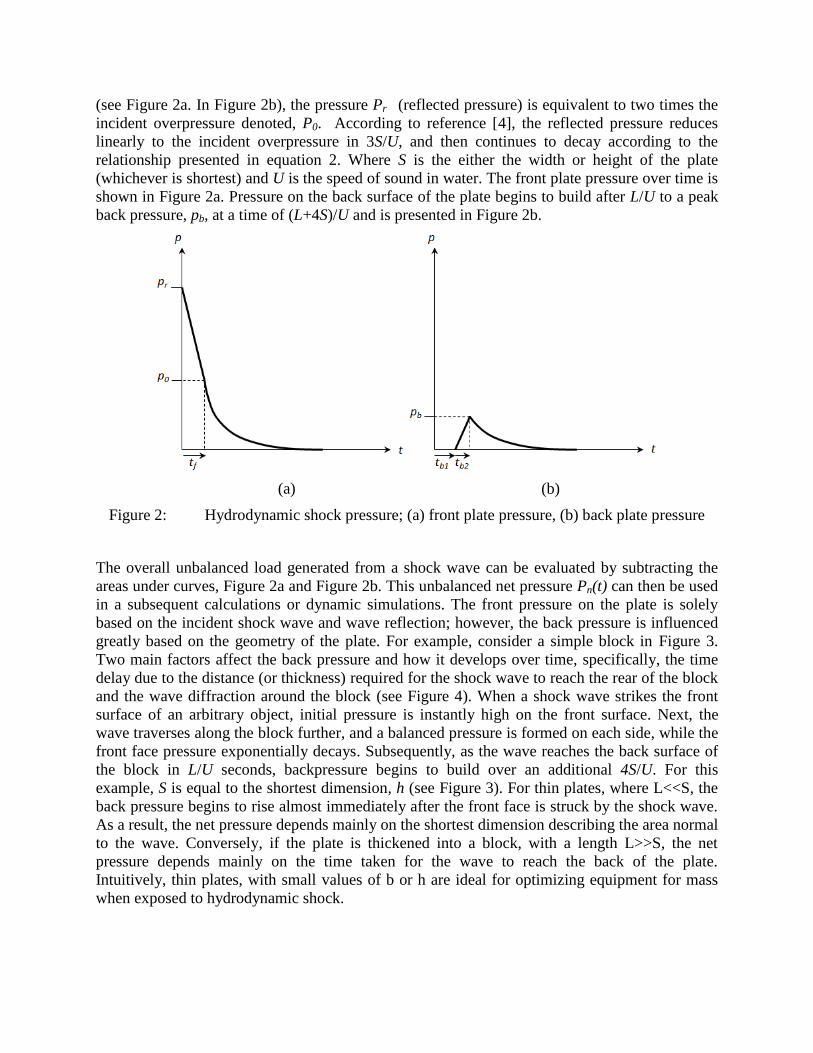
designed to have a natural frequency of 10 Hz. The geometry of the block exposed to shock is
shown in Figure 6, where the base and width are 500 mm and 500 mm respectively, and the
thickness of the block is 200 mm. The block is much thicker than a thin plate and consequently a
time delay in back pressure stabilizing is apparent in Figure 7. The net pressure, as indicated in
purple, is used for as the time varying pressure for both methodologies. The mass of the light
weight block is 100 kg with added mass of,
kgbamadded 6.1345.025.01027335.1335.122
where, the density of water is 1027 kg/m3 at 10
oC.
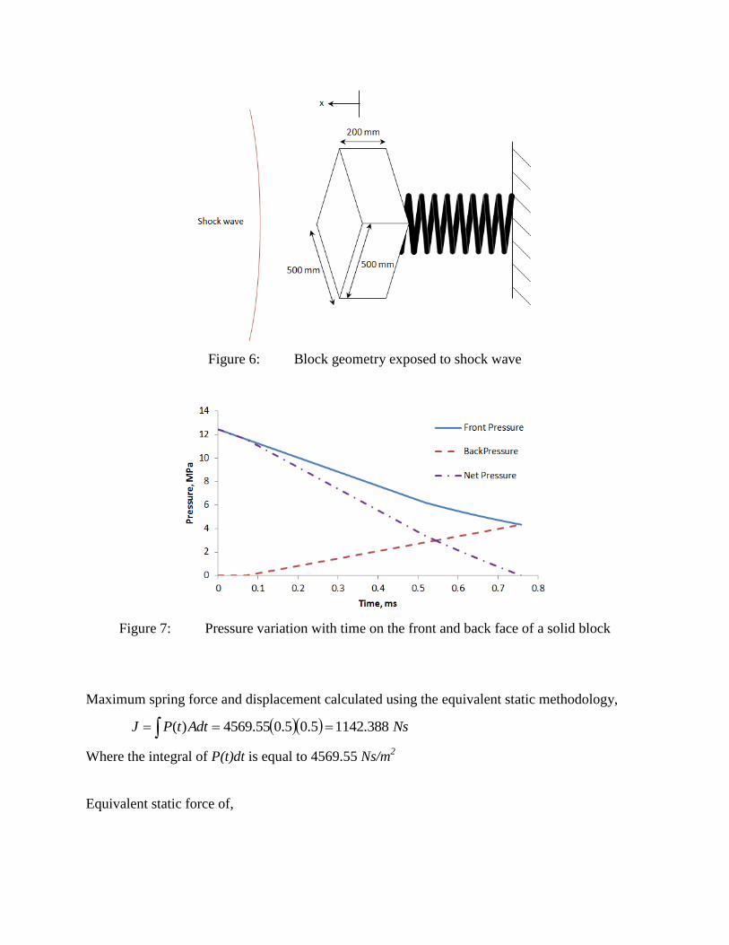
Figure 6: Block geometry exposed to shock wave
Figure 7: Pressure variation with time on the front and back face of a solid block
Maximum spring force and displacement calculated using the equivalent static methodology,
NsAdttPJ 388.11425.05.055.4569)(
Where the integral of P(t)dt is equal to 4569.55 Ns/m2
Equivalent static force of,

NJm
kJFhse 778,71210388.1142
2
and the corresponding spring deflection is,
mm
Fhse 0775.02
A blast wave is applied to a simple mass spring system using commercial ANSYS® simulating
software, with time varying spring forces and spring elongation demonstrated in Figure 8a and
Figure 8b, respectively. For this example, damping and added mass was not included in the
system. As a result the time histories for force and deflection for this ideal system has constant
amplitudes. The motivation of presenting this example is to show how shock mounted equipment
can be idealized as a mass spring system and transient hydrodynamic impulses can be evaluated
accurately by both applied equations and simulation. In Table 1, a comparison between the static
equivalent calculations and commercial software is presented. The difference between the two
methods should be identical; however, given approximations in the integral of the impulse a
0.54% error is acceptable. If damping is included in the current mass-spring system the response
to the same shock wave is presented in the Figure 9.
(a) (b)
Figure 8: Dynamic response of a mass spring system (a) force, (b) elongation
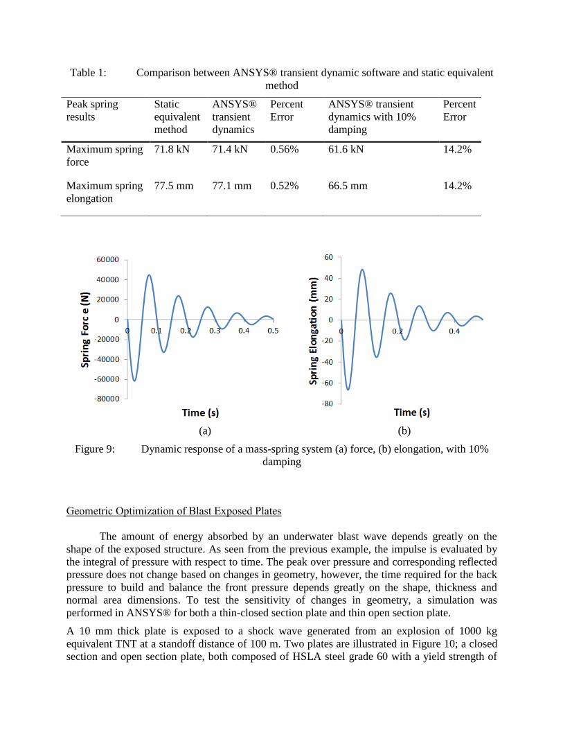
Table 1: Comparison between ANSYS® transient dynamic software and static equivalent
method
Peak spring
results
Static
equivalent
method
ANSYS®
transient
dynamics
Percent
Error
ANSYS® transient
dynamics with 10%
damping
Percent
Error
Maximum spring
force
71.8 kN 71.4 kN 0.56%
61.6 kN 14.2%
Maximum spring
elongation
77.5 mm 77.1 mm 0.52% 66.5 mm
14.2%
(a) (b)
Figure 9: Dynamic response of a mass-spring system (a) force, (b) elongation, with 10%
damping
Geometric Optimization of Blast Exposed Plates
The amount of energy absorbed by an underwater blast wave depends greatly on the
shape of the exposed structure. As seen from the previous example, the impulse is evaluated by
the integral of pressure with respect to time. The peak over pressure and corresponding reflected
pressure does not change based on changes in geometry, however, the time required for the back
pressure to build and balance the front pressure depends greatly on the shape, thickness and
normal area dimensions. To test the sensitivity of changes in geometry, a simulation was
performed in ANSYS® for both a thin-closed section plate and thin open section plate.
A 10 mm thick plate is exposed to a shock wave generated from an explosion of 1000 kg
equivalent TNT at a standoff distance of 100 m. Two plates are illustrated in Figure 10; a closed
section and open section plate, both composed of HSLA steel grade 60 with a yield strength of
414 MPa (60 ksi) and an ultimate tensile strength of 517 MPa (75 ksi). The boundary conditions
of both plates include simply-supported constraints along the external edges. The corresponding
pressures are presented in Figure 11 for the closed and open section respectively. Subsequently,
the maximum reflected pressure, distributed over the front face of each plate, is initially
identical, at 7.5 MPa. Eliminating the center of the plate decreases the amount of time required
for the pressure on the plate to reach hydrostatic pressure. Consequently, the net pressure
between the front and back face for the open section plate goes to zero nearly 5 times faster than
the closed section. In contrast, net pressure durations on each plate and their magnitude are
governed by wave diffraction, and therefore change for changes in width, angle and thickness.
For simplicity, the angle of each plate is placed a 900 to the wave flow to avoid oblique wave
diffraction.
Mass of the closed section plate is,
kgmCS 62.195.05.001.07850
Hydrodynamic mass is included to each simulation based on the section entitled “hydrodynamic
mass”,
kgbam CSadded 8.1002
,
The total mass of the closed section plate is,
kgm TotalCS 5.120,
Mass of the closed section plate is,
kgmOS 07.74.025.0205.001.07850
Hydrodynamic mass,
kgbam OSadded 5.1445.0405.0102722
,
The total mass of the closed section plate is,
kgm TotalOS 6.21,
For the both simulations, damping has been included using the Rayleigh damping model. A
stiffness coefficient based on a damping ratio of 0.1 on the fundamental frequency response of
each plate was implemented. The 1st natural frequency of the closed section plate is 77 Hz,
whereas, the open plate geometry is much stiffer with a fundamental frequency of 304 Hz.

Figure 10: Closed and open section plates geometries
(a) (b)
Figure 11: Pressure variations with time for, (a) closed section plate, and (b) open section
plate
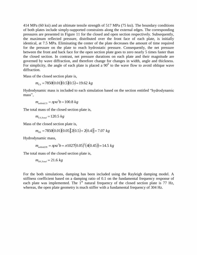
The von-Mises stress was calculated for each incremental time step for each simulation with the
peak stress, over duration of 0.1s presented in Figure 12. The closed section plate exhibits stress
2.3 times higher than the stress indicated in the response of an open section. The maximum stress
for the open section is 388 MPa resulting in a factor of safety of 1, whereas the close section
plate has a peak stress of 878 MPa, 2.1 times higher than the yield strength of the material.
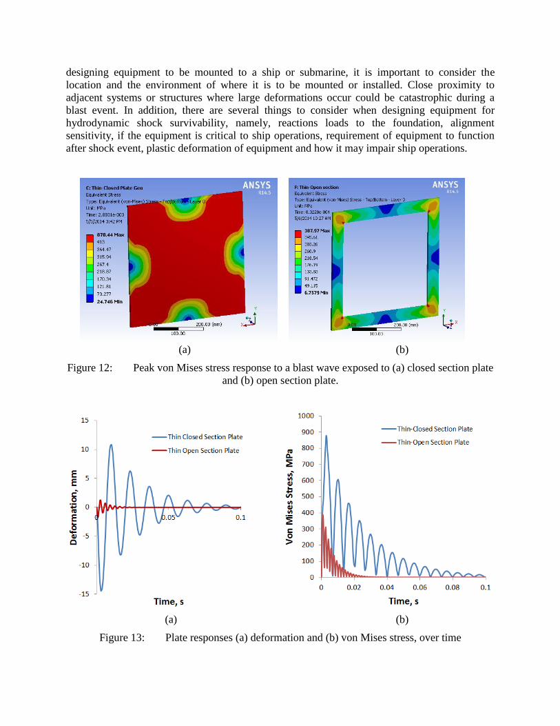
Deformation in the plate over time is presented in Figure 13. In Figure 13a and Figure 13b, the
amplitudes for both stress and deformation tend to dampen out after 0.1 s, and the magnitude of
the deformation of the closed section plate is 8.2 times greater than the open section plate. When
designing equipment to be mounted to a ship or submarine, it is important to consider the
location and the environment of where it is to be mounted or installed. Close proximity to
adjacent systems or structures where large deformations occur could be catastrophic during a
blast event. In addition, there are several things to consider when designing equipment for
hydrodynamic shock survivability, namely, reactions loads to the foundation, alignment
sensitivity, if the equipment is critical to ship operations, requirement of equipment to function
after shock event, plastic deformation of equipment and how it may impair ship operations.
(a) (b)
Figure 12: Peak von Mises stress response to a blast wave exposed to (a) closed section plate
and (b) open section plate.
(a) (b)
Figure 13: Plate responses (a) deformation and (b) von Mises stress, over time

Conclusion
Design optimization of naval equipment mounted to surface ships or submarines is the
key motivation of this review. Indal technologies, a large international provider of towed array
handling equipment for submarines, designs submersed equipment to comply with a high
standard of shock. A number of techniques have been presented in this paper regarding the
strategy for evaluating the underwater shock on submersed equipment, i.e., wave diffraction and
manipulation of surface dimensions, hydrodynamic static equivalency, shock transparency on
cylindrical geometries and transient dynamic simulation of closed and open sections. It is
important to acknowledge, hydrodynamic shock may not always govern the optimization of a
design, other considerations such as mechanical shock, environmental loads and operational
loads may also be design drivers. However, if the equipment geometry is not optimized for wave
diffraction and corresponding transient dynamic responses, hydrodynamic shock could be
catastrophic to equipment or structures.
Hydrodynamic static equivalent method was first reviewed in this paper, based on energy
and momentum conservation has been shown to agree well with a full transient dynamic
simulation in ANSYS®. Moreover, the method has been shown to be conservative for highly
damped systems.
Dynamic simulations were conducted in ANSYS® for both a closed and an open flat
plate, where it has been demonstrated the closed section plate exceeds the ultimate strength
based on the standoff and equivalent TNT. Consequently, by removing material from the plate to
form the open plate geometry, the duration of wave diffraction and corresponding net pressure,
drops significantly across the surface. It has been shown with this removal of material, the mass
and hydrodynamic mass have lowered and the peak stress on the plate has reduced under the
yield strength. In addition, the deformation of the open plate was 8.2 times less for the same
impulse as the closed plate.
Through different techniques discussed in this review, a significant reduction in mass and
corresponding cost has been demonstrated.
References
1. Keil, A. H., 1961., The response of ships to underwater explosions, Structural mechanics
laboratory research and development-department of the navy David Taylor model basin,
Report 1576.4
2. Rajendran R., Paik J. K. and Lee, J. M., 2007. Underwater explosion experiments of
plane plates. Society for experimental mechanics.
3. Rajendran, R. and. Lee, J. M., 2008. Blast loaded plates. Marine Structures, 1-29.
4. Glasstone, S. and Dolan, P. J., 1977. The effects of nuclear weapons, Third Edition.
United States department of defense and United States department of energy.

5. Reid, W. D., 1996. The response of surface ships to underwater explosions. Ship
structures and materials division, aeronautical and maritime research laboratory,
Department of defense, defense science and technology organization, DSTO-GD-0109.
6. Brennen, C. E., 1982. A review of added mass and fluid inertial forces. Naval civil
engineering laboratory, Port Hueneme, California.
7. Huang, H., 1979. Transient response of two fluid filled-coupled cylindrical elastic shells
to an incident pressure pulse. Journal of Applied Mechanics 46, 513-518.
8. Iakovlev, S., 2007. Submerged fluid-filled cylindrical shell subjected to a shock wave:
Fluid-structure interaction effects. Journal of Fluids and Structures 23, 117-142.

CURTISSWRIGHTDS.COM© 2015 Curtiss-Wright. All rights reserved. Specifications are subject to change without notice. All trademarks are property of their respective owners.
Info
curtisswrightds.com