dr. alaadin a. bukhari centre for environment and water research institute kfupm tertiary treatment...
TRANSCRIPT

Dr. Alaadin A. Bukhari
Centre for Environment and Water
Research Institute
KFUPM
Tertiary Treatment of Domestic Wastewater
By

PRESENTATION LAYOUT
• Introduction
• Tertiary Treatment Technologies
• Removal of Residual Constituents
– Suspended Solids Removal
– Nutrients Removal
– Removal of Toxic Compounds
– Removal of Dissolved Inorganic Compounds
• Tertiary Treatment of Wastewater in Saudi
Arabia
• Summary

• DefinitionFurther removal of suspended and dissolved contaminants, not normally removed by conventional treatment
InfluentIn fluent E ffluent
P rim arycla rifie r
A era tiontank
Secondaryclarifier
T ertia rytrea tm ent
un it
INTRODUCTION
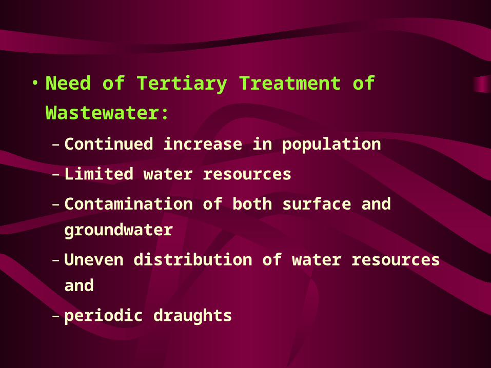
• Need of Tertiary Treatment of Wastewater:
– Continued increase in population
– Limited water resources
– Contamination of both surface and groundwater
– Uneven distribution of water resources and
– periodic draughts

• Typical Constituents Present in Wastewater:
– Suspended solids
– Biodegradable organics compounds
– Volatile organic compounds
– Toxic contaminants
– Nutrients
– Other organics and inorganics

•Options for reuse of treated wastewater

TERTIARY TREATMENT TECHNOLOGIES
• Classification of Technologies
• Primary Treatment Systems
• Secondary Treatment Systems
• Tertiary Treatment Systems


• Factors affecting the selection of treatment processes:
– The potential use of the treated effluent
– The nature of the wastewater
– The compatibility of the various operations
and processes
– The available means to dispose of the
ultimate contaminants, and
– The environmental and economic feasibility
of the various systems

Typical performance data:

• What are the contaminants removed during tertiary treatment?
– Suspended solids
– Nutrients
– Toxic compounds
– Dissolved organics and inorganics

REMOVAL OF RESIDUAL CONSTITUNTS
• Suspended Solids Removal:
– Granular-medium filters
• the bed depth
• the type of filtering medium used
• whether the filtering medium is stratified or unstratified
• the type of operation
– Microstrainers
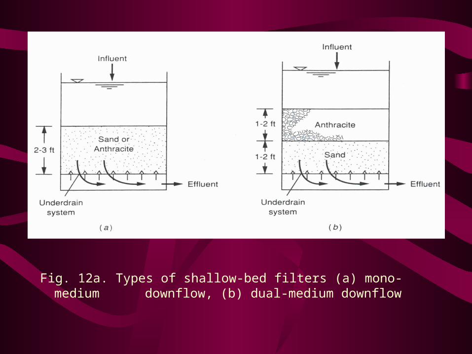
Fig. 12a. Types of shallow-bed filters (a) mono-medium downflow, (b) dual-medium downflow

Fig. 12b. Types of deep-bed filters (a) mono-medium downflow, (b) mono-medium upflow


• Sizing of a filter:– Principal design criteria of a filter design is water
flow rate and head loss
– Usually we know• flow rate of influent
• surface loading rate
Flow rate Surface area of filtering unit = --------------------------
Surface loading rate
• Head loss can be calculated using reference (MetCalf & Eddy, 1991)

• Removal of Suspended Solids by Microscreaning:


• (II) Nutrients Removal
Basic nutrients present in the domestic wastewater are
– Nitrogen (ammonia, nitrite, nitrate)
– Phosphorus (soluble and insoluble)
– Sulfate
– Other compounds of nitrogen & phosphorus
Problems associated with nutrients presence in wastewater are– accelerate the eutrophication
– stimulate the growth of algae & rooted aquatic plants
– aesthetic problems & nuisance

– depleting D.O. concentration in receiving waters
– Toxicity towards aquatic life
– increasing chlorine demand
– presenting a public health hazard
– affecting the suitability of wastewater for reuse
• Nutrient Control could be accomplished by:
– physical methods
– chemical methods, and
– biological methods

Control and Removal of Nitrogen (Biologically):
• Removal of Nitrogen by Nitrification/Denitrification Processes:– It is a two step processes
aerobicNH4
- —> NO3- (nitrification)
anoxicNO3
- —> N2 (denitrification)
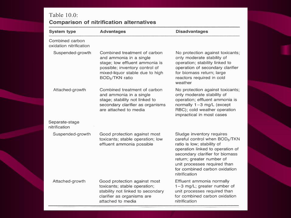
• Removal of Nitrogen by Nitrification Processes:– 1) Single-stage process– 2) Separate-stage process

In fluent E ffluentP rim arycla rifie r
N itrifica tiontank
N itrifica tioncla rifie r
Prim ary s ludge
Returned s ludge
W aste s ludge
Fig. 8a. Typical carbon oxidation and nitrification processes (single-stage)

Secondaryc larifier
E ffluentN itrifica tiontank
N itrifica tionc larifier
R eturned s ludge
W aste s ludge
In fluent Prim aryc larifier
A erob ictank (B O D )
P rim ary s ludge
R eturned s ludge
W aste s ludge
Fig. 8b. Typical carbon oxidation and nitrification processes (separate-stage)

• Nitrification/Denitrification systems can be
classified as:
(a) Combined Nitrification/Denitrification Systems
1) Bardenpho process(four stage)
2) Oxidation Ditch process
(b) Separate-Stage Denitrification Systems

Fig. 9a. Combined-stage nitrification/denitrification system (four-stage Bardenpho)
E ffluentAerobiczone
Secondaryc larifier
W aste s ludge
In fluent Aerobic com binedoxidation n itrification
zone
R eturned s ludge
Anoxicdenitrification
zone
Anoxicdenitrification
zone
M ixed liquor re tu rn

Fig. 9b. Combined-stage nitrification/denitrification system (oxidation ditch)
A erator
Aerobic zone
Anoxic zone
In fluent
Secondaryclarifier
R eturn s ludge
W aste s ludge
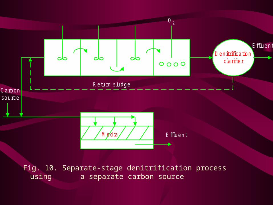
Fig. 10. Separate-stage denitrification process using a separate carbon source
O 2
D enitrifica tioncla rifie r
R eturn s ludge
E ffluent
E ffluentM edia
C arbonsource

• Control and Removal of Nitrogen (Physical &
Chemical Methods):
– air Stripping
– breakpoint chlorination
– selective ion exchange

V ent
In flow
P acking m edia
E ffluentA ir
Fig. 11. Cross-section of a countercurrent ammonia-stripping tower

• Breakpoint chlorination:
– Oxidation of ammonia-nitrogen can be done by adding
excess chlorine
– Basic chemical equations:
Cl2 + H2O HOCl + H+ + Cl-
NH3 + HOCl N2 + N2O + NO2- + NO3
- + Cl-

• Ion exchange process
In itia l s tage F ina l stage
N H 3
N a +
C a ++
N a +
etc.
K +
N a +
C a ++
N H 3
N H 3
N H 3
N H 3
Ion exchangesites
In fluent
E ffluent


Phosphorus Removal Biologically:
Key to the biological phosphorus removal is the exposure of the microorganisms to alternating anaerobic & aerobic conditions
• Phosphorus Removal Processes
– (1) Mainstream process
– (2) Sidestream process
– (3) Sequencing Batch Reactor (SBR)

C larifie r
R eturn s ludge W aste
In fluent
E ffluent
A naerob icstages
O xic stages
Fig. 12a. Biological phosphorus removal (mainstream process)

In fluent E ffluentA era tion basin cla rifie r
R eturned s ludge
W aste s ludge
A naerob icphosphorus
stripper
Fig. 12a. Biological phosphorus removal (sidestream process)

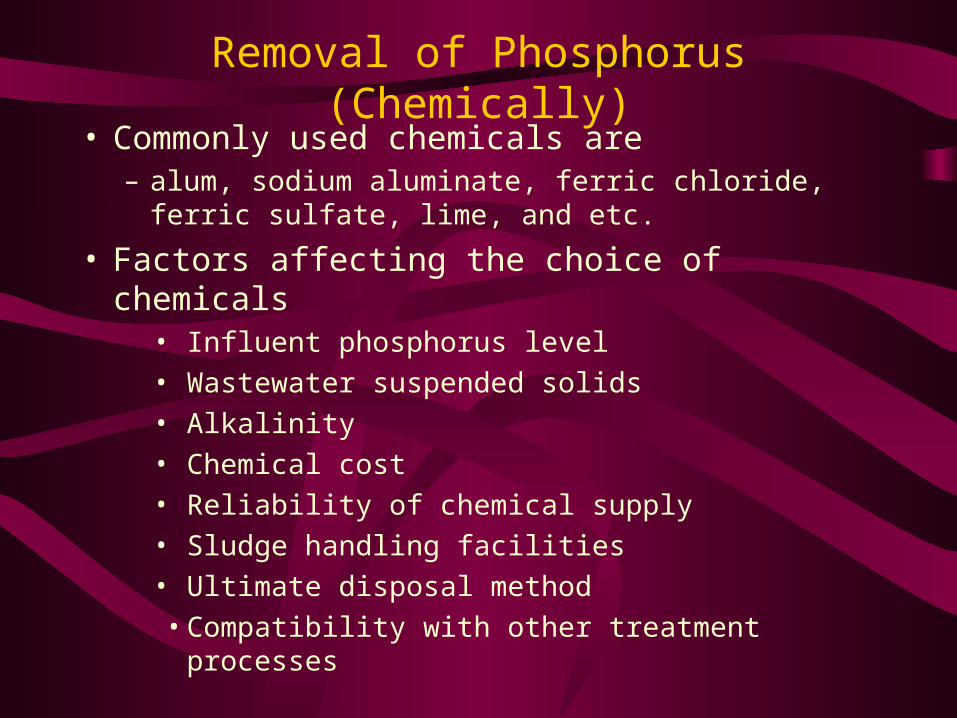
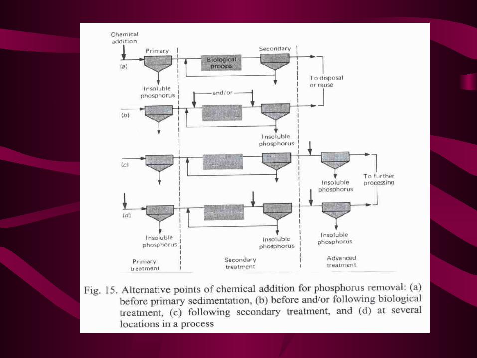
Removal of Phosphorus (Chemically)• Commonly used chemicals are
– alum, sodium aluminate, ferric chloride, ferric sulfate, lime, and etc.
• Factors affecting the choice of chemicals• Influent phosphorus level
• Wastewater suspended solids
• Alkalinity
• Chemical cost
• Reliability of chemical supply
• Sludge handling facilities
• Ultimate disposal method
• Compatibility with other treatment processes


(III) Removal of Toxic Compounds:
Special attention is given to priority pollutants &
refractory organic compounds in recent years, due to:
– carcinogenic
– mutagenic
– teratogenic
– they are resistant to microbial degradation

• Treatment methods
– Biological
– Chemical
• chemical oxidation
• coagulation, sedimentation, and filtration
– Physical
• carbon adsorption
• air stripping

• (1) Carbon Adsorption:
It is an advanced wastewater treatment method
used for the removal of refrectory organic
compounds as well as residual amount of
inorganic compounds
• Types of carbon contactors:
• Upflow columns
• Downflow columns
• Fixed beds
• Expanded beds

Fig. 17. Typical upflow countercurrent carbon column
B ack wash dra in
In fluent
U nderdra in system
C arbon filling port
E ffluent
Carbon colum n
W astewater flow

(2) Chemical Oxidation:
Chemical oxidation mainly done by
– chlorine
– chlorine dioxide, and
– ozone
Basic chemical equation:
Oxidant + Compound CO2 + H2O + other products

(IV) Removal of Dissolved Inorganic Compounds
– chemical precipitation
– ion exchange
– ultra-filtration
– reverse osmosis
– electrodialysis
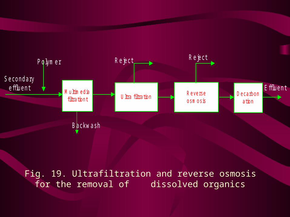
S econdaryeffluen t
U ltra filtra tionM ultim edia
filtra tiontD ecarbon
ationR everseosm osis
P olym er
B ackwash
R eject R e ject
E ffluent
Fig. 19. Ultrafiltration and reverse osmosis for the removal of dissolved organics
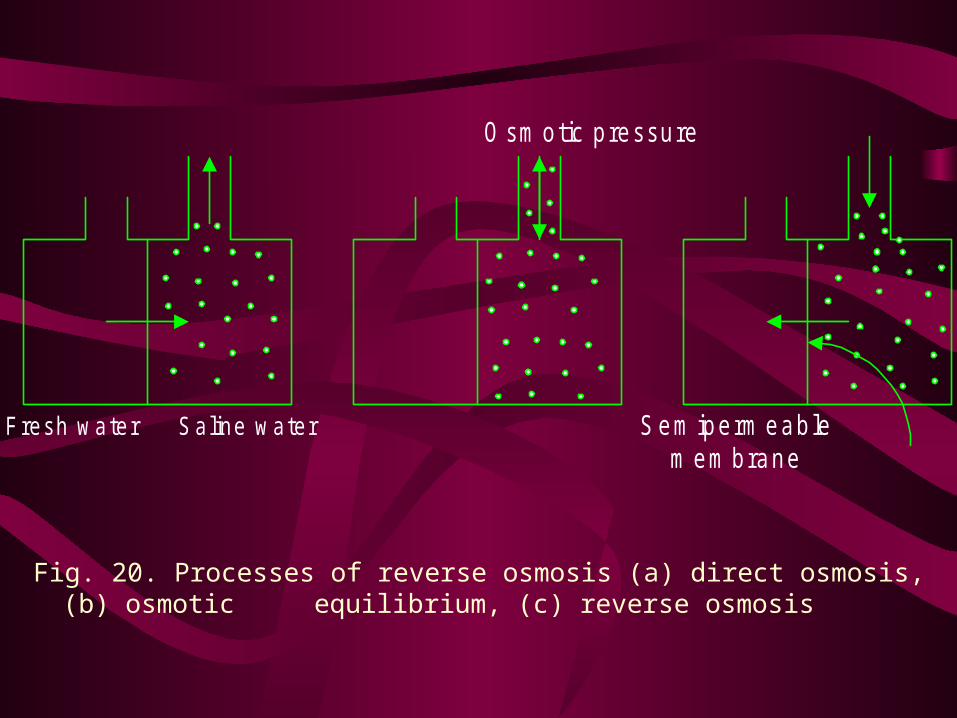
Fig. 20. Processes of reverse osmosis (a) direct osmosis, (b) osmotic equilibrium, (c) reverse osmosis
Fresh water Saline water S em iperm eablem em brane
O sm otic p ressure


Tertiary Treatment of Wastewater in Saudi Arabia
• Large quantity of wastewater is being generated in
kingdom of Saudi Arabia
• Quantities of wastewater generated
– In 1994: Water Demand = 1.8 billion m3
– WW Generated = 1.0 billion m3
– WW Treated = 0.4 billion m3
– WW Recycled = 0.1 billion m3
– Water Demand in year 2000 = 2.8 billion m3
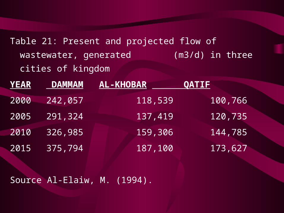
Table 21: Present and projected flow of wastewater, generated
(m3/d) in three cities of kingdom
YEAR DAMMAM AL-KHOBAR QATIF
2000 242,057 118,539 100,766
2005 291,324 137,419 120,735
2010 326,985 159,306 144,785
2015 375,794 187,100 173,627
Source Al-Elaiw, M. (1994).

• Secondary treatment is practiced in Dammam,
Khobar, Qatif and Khafji
• Tertiary treatment is practiced in Royal
Commission of Jubail and Yanbu (RCJY)
• In Jubail 100% of tertiary treated wastewater is
being reused


• Summary:– Growing demand and scarcity of water resources
necessitate the need for the tertiary treatment of
wastewater for reuse purposes
– Tertiary treatment of wastewater mainly depends on the
availability and practicality of technologies
– Selection of the processes depends on the requirement
– Residual contaminants to be removed during tertiary
treatment are suspended solids, nutrients, toxic
compounds, and dissolved inorganics
