dpp iec · 3dpp040-*** 40 40 93% 87% 228 99 79 125 438 111 48 61 gtd3x 2900 975 32201 240vdc (120...
TRANSCRIPT
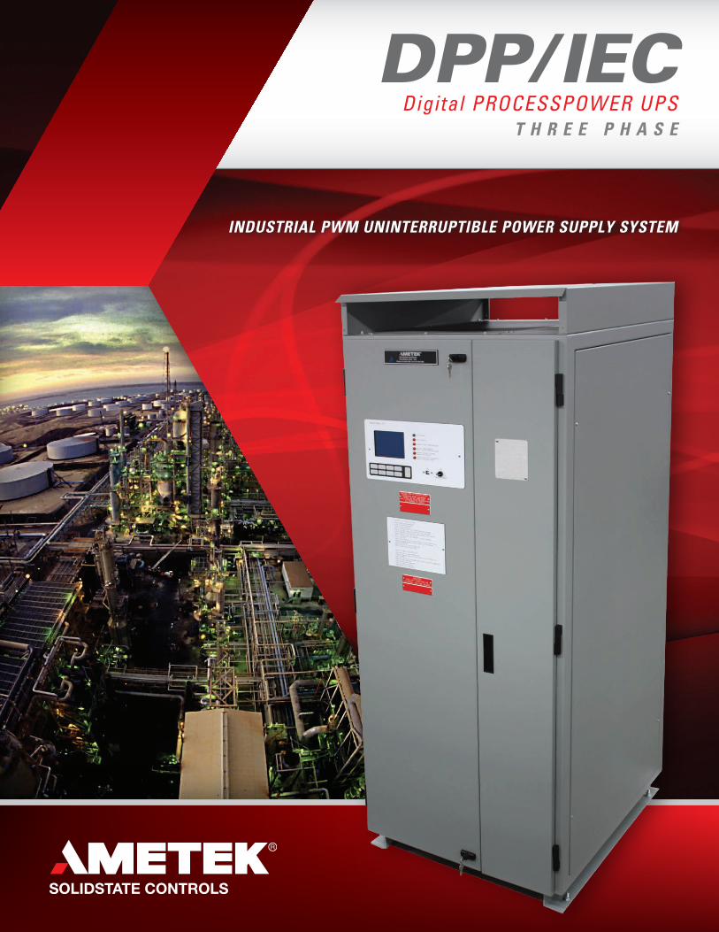
INDUSTRIAL PWM UNINTERRUPTIBLE POWER SUPPLY SYSTEM
DPP/IEC Digital PROCESSPOWER UPS
T H R E E P H A S E
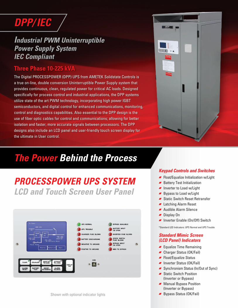
Keypad Controls and Switches Float/Equalize Initialization w/Light Battery Test Initialization Inverter to Load w/Light Bypass to Load w/Light Static Switch Reset Retransfer Latching Alarm Reset Audible Alarm Silence Display On Inverter Enable (On/Off) Switch
*Standard LED Indicators: UPS Normal and UPS Trouble
Standard Mimic Screen (LCD Panel) Indicators
Equalize Time Remaining Charger Status (OK/Fail) Float/Equalize Status Inverter Status (OK/Fail) Synchronism Status (In/Out of Sync) Static Switch Position
(Inverter or Bypass) Manual Bypass Position
(Inverter or Bypass) Bypass Status (OK/Fail)
DPP/ IEC
Industrial PWM Uninterruptible Power Supply System IEC Compliant
Three Phase 10-225 kVAThe Digital PROCESSPOWER (DPP) UPS from AMETEK Solidstate Controls is a true on-line, double conversion Uninterruptible Power Supply system that provides continuous, clean, regulated power for critical AC loads. Designed specifically for process control and industrial applications, the DPP systems utilize state of the art PWM technology, incorporating high power IGBT semiconductors, and digital control for enhanced communications, monitoring, control and diagnostics capabilities. Also essential to the DPP design is the use of fiber optic cables for control and communications; allowing for better isolation and faster, more accurate signals between processors. The DPP designs also include an LCD panel and user-friendly touch screen display for the ultimate in User control.
PROCESSPOWER UPS SYSTEM LCD and Touch Screen User Panel
Shown with optional indicator lights
The Power Behind the Process
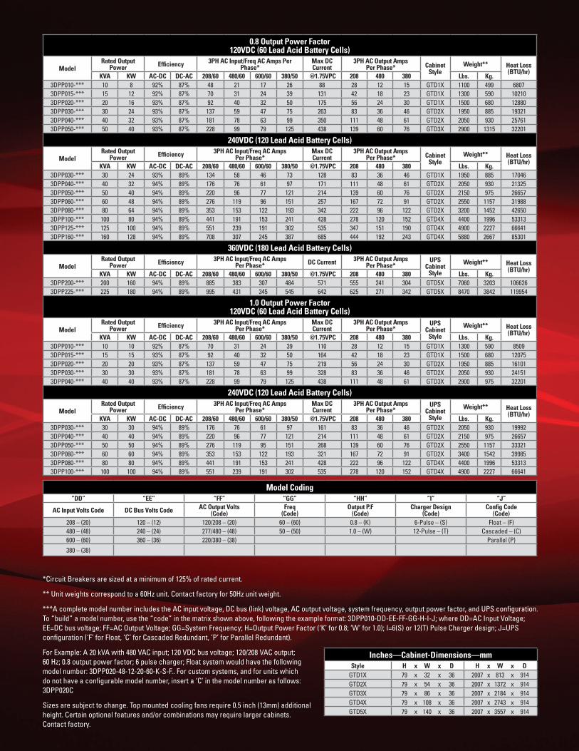
0.8 Output Power Factor120VDC (60 Lead Acid Battery Cells)
ModelRated Output
Power Efficiency 3PH AC Input/Freq AC Amps Per Phase*
Max DC Current
3PH AC Output Amps Per Phase* Cabinet
StyleWeight** Heat Loss
(BTU/hr)KVA KW AC-DC DC-AC 208/60 480/60 600/60 380/50 @1.75VPC 208 480 380 Lbs. Kg.
3DPP010-*** 10 8 92% 87% 48 21 17 26 88 28 12 15 GTD1X 1100 499 68073DPP015-*** 15 12 92% 87% 70 31 24 39 131 42 18 23 GTD1X 1300 590 102103DPP020-*** 20 16 93% 87% 92 40 32 50 175 56 24 30 GTD1X 1500 680 128803DPP030-*** 30 24 93% 87% 137 59 47 75 263 83 36 46 GTD2X 1950 885 193213DPP040-*** 40 32 93% 87% 181 78 63 99 350 111 48 61 GTD2X 2050 930 257613DPP050-*** 50 40 93% 87% 228 99 79 125 438 139 60 76 GTD3X 2900 1315 32201
240VDC (120 Lead Acid Battery Cells)
ModelRated Output
Power Efficiency 3PH AC Input/Freq AC Amps Per Phase*
Max DC Current
3PH AC Output Amps Per Phase* Cabinet
StyleWeight** Heat Loss
(BTU/hr)KVA KW AC-DC DC-AC 208/60 480/60 600/60 380/50 @1.75VPC 208 480 380 Lbs. Kg.
3DPP030-*** 30 24 93% 89% 134 58 46 73 128 83 36 46 GTD1X 1950 885 170463DPP040-*** 40 32 94% 89% 176 76 61 97 171 111 48 61 GTD2X 2050 930 213253DPP050-*** 50 40 94% 89% 220 96 77 121 214 139 60 76 GTD2X 2150 975 266573DPP060-*** 60 48 94% 89% 276 119 96 151 257 167 72 91 GTD2X 2550 1157 319883DPP080-*** 80 64 94% 89% 353 153 122 193 342 222 96 122 GTD2X 3200 1452 426503DPP100-*** 100 80 94% 89% 441 191 153 241 428 278 120 152 GTD4X 4400 1996 533133DPP125-*** 125 100 94% 89% 551 239 191 302 535 347 151 190 GTD4X 4900 2227 666413DPP160-*** 160 128 94% 89% 708 307 245 387 685 444 192 243 GTD4X 5880 2667 85301
360VDC (180 Lead Acid Battery Cells)
ModelRated Output
Power Efficiency 3PH AC Input/Freq AC Amps Per Phase* DC Current 3PH AC Output Amps
Per Phase*UPS
Cabinet Style
Weight** Heat Loss (BTU/hr)
KVA KW AC-DC DC-AC 208/60 480/60 600/60 380/50 @1.75VPC 208 480 380 Lbs. Kg.3DPP200-*** 200 160 94% 89% 885 383 307 484 571 555 241 304 GTD5X 7060 3203 1066263DPP225-*** 225 180 94% 89% 995 431 345 545 642 625 271 342 GTD5X 8470 3842 119954
1.0 Output Power Factor120VDC (60 Lead Acid Battery Cells)
ModelRated Output
Power Efficiency 3PH AC Input/Freq AC Amps Per Phase*
Max DC Current
3PH AC Output Amps Per Phase*
UPS Cabinet
Style
Weight** Heat Loss (BTU/hr)
KVA KW AC-DC DC-AC 208/60 480/60 600/60 380/50 @1.75VPC 208 480 380 Lbs. Kg.3DPP010-*** 10 10 92% 87% 70 31 24 39 110 28 12 15 GTD1X 1300 590 85093DPP015-*** 15 15 93% 87% 92 40 32 50 164 42 18 23 GTD1X 1500 680 120753DPP020-*** 20 20 93% 87% 137 59 47 75 219 56 24 30 GTD2X 1950 885 161013DPP030-*** 30 30 93% 87% 181 78 63 99 328 83 36 46 GTD2X 2050 930 241513DPP040-*** 40 40 93% 87% 228 99 79 125 438 111 48 61 GTD3X 2900 975 32201
240VDC (120 Lead Acid Battery Cells)
ModelRated Output
Power Efficiency 3PH AC Input/Freq AC Amps Per Phase*
Max DC Current
3PH AC Output Amps Per Phase*
UPS Cabinet
Style
Weight** Heat Loss (BTU/hr)
KVA KW AC-DC DC-AC 208/60 480/60 600/60 380/50 @1.75VPC 208 480 380 Lbs. Kg.3DPP030-*** 30 30 94% 89% 176 76 61 97 161 83 36 46 GTD2X 2050 930 199923DPP040-*** 40 40 94% 89% 220 96 77 121 214 111 48 61 GTD2X 2150 975 266573DPP050-*** 50 50 94% 89% 276 119 95 151 268 139 60 76 GTD2X 2550 1157 333213DPP060-*** 60 60 94% 89% 353 153 122 193 321 167 72 91 GTD2X 3400 1542 399853DPP080-*** 80 80 94% 89% 441 191 153 241 428 222 96 122 GTD4X 4400 1996 533133DPP100-*** 100 100 94% 89% 551 239 191 302 535 278 120 152 GTD4X 4900 2227 66641
Model Coding“DD” “EE” “FF” “GG” “HH” “I” “J”
AC Input Volts Code DC Bus Volts Code AC Output Volts (Code)
Freq(Code)
Output P.F(Code)
Charger Design (Code)
Config Code(Code)
208 – (20) 120 – (12) 120/208 – (20) 60 – (60) 0.8 – (K) 6-Pulse – (S) Float – (F)480 – (48) 240 – (24) 277/480 – (48) 50 – (50) 1.0 – (W) 12-Pulse – (T) Cascaded – (C)600 – (60) 360 – (36) 220/380 – (38) Parallel (P)
380 – (38)
*Circuit Breakers are sized at a minimum of 125% of rated current.
** Unit weights correspond to a 60Hz unit. Contact factory for 50Hz unit weight.
***A complete model number includes the AC input voltage, DC bus (link) voltage, AC output voltage, system frequency, output power factor, and UPS configuration. To “build” a model number, use the “code” in the matrix shown above, following the example format: 3DPP010-DD-EE-FF-GG-H-I-J; where DD=AC Input Voltage; EE=DC bus voltage; FF=AC Output Voltage; GG=System Frequency; H=Output Power Factor (‘K’ for 0.8; ‘W’ for 1.0); I=6(S) or 12(T) Pulse Charger design; J=UPS configuration (‘F’ for Float, ‘C’ for Cascaded Redundant, ‘P’ for Parallel Redundant).
For Example: A 20 kVA with 480 VAC input; 120 VDC bus voltage; 120/208 VAC output; 60 Hz; 0.8 output power factor; 6 pulse charger; Float system would have the following model number: 3DPP020-48-12-20-60-K-S-F.. For custom systems, and for units which do not have a configurable model number, insert a ‘C’ in the model number as follows: 3DPP020C
Sizes are subject to change. Top mounted cooling fans require 0.5 inch (13mm) additional height. Certain optional features and/or combinations may require larger cabinets. Contact factory.
Inches—Cabinet-Dimensions—mmStyle H x W x D H x W x D
GTD1X 79 x 32 x 36 2007 x 813 x 914GTD2X 79 x 54 x 36 2007 x 1372 x 914GTD3X 79 x 86 x 36 2007 x 2184 x 914GTD4X 79 x 108 x 36 2007 x 2743 x 914GTD5X 79 x 140 x 36 2007 x 3557 x 914

English: www.solidstatecontrolsinc.com Nuclear: www.nuclearups.com
Spanish: www.solidstatecontrolsinc-esp.com
Russian: www.solidstatecontrolsinc-ru.comChinese: www.solidstatecontrolsinc-chn.com
Brazilian Portuguese: www.solidstatecontrolsinc-bz.com
VISIT OUR WEBSITES:
REV 1-12-2017
All Facilities are ISO 9001 Certified
World Headquarters875 Dearborn Drive Columbus, Ohio 43085 Phone: +1-614-846-7500 Toll Free: +1-800-635-7300 Fax: +1-614-885-3990
Mexico HeadquartersCamino a la Montaña 178-101La Perla, Naucalpan Estado de México53340Phone: (55) 55250-1232Fax: (55) 5203-7981
Asia Pacific HeadquartersAMETEK Singapore Office 43 Changi South Ave. 2 #04-01 Singapore 486164 Phone: +65-6484-2388 Fax: +65-6481-6588
Brazil HeadquartersAMETEK do Brasil Ltda Rod. Eng° Ermênio de Oliveira Penteado (SP75) - Km 57, Barrio Tombadouro Indaiatuba - SP - Brasil, 13337-300 Phone: +55-16-2107-4100
Middle East OfficesDubaiP.O.Box 337164Office 2004 , X2 BuildingJumeirah Lakes Towers JLTDubai – UAEPhone: +971544300331 Saudi ArabiaKing Khalid Street, ATCO BuildingDammam, Saudi ArabiaPhone: +966 13 833 2339 ext. 654Direct: +966 830 5482Cell: +966 55 888 7860
India HeadquartersAMETEK Instruments India Private Limited Plot 148, EPIP Zone Phase 2 Featherlite Tech Park, 1st Floor Whitefield, Bangalore - 560066 Karnataka, INDIA Phone: +91 70222 53258 Fax: +91 80 6782 3232
Argentina HeadquartersOlive 1954Rosario 2000 – Sta Fe, ArgentinaPhone: +54 341 455 3332
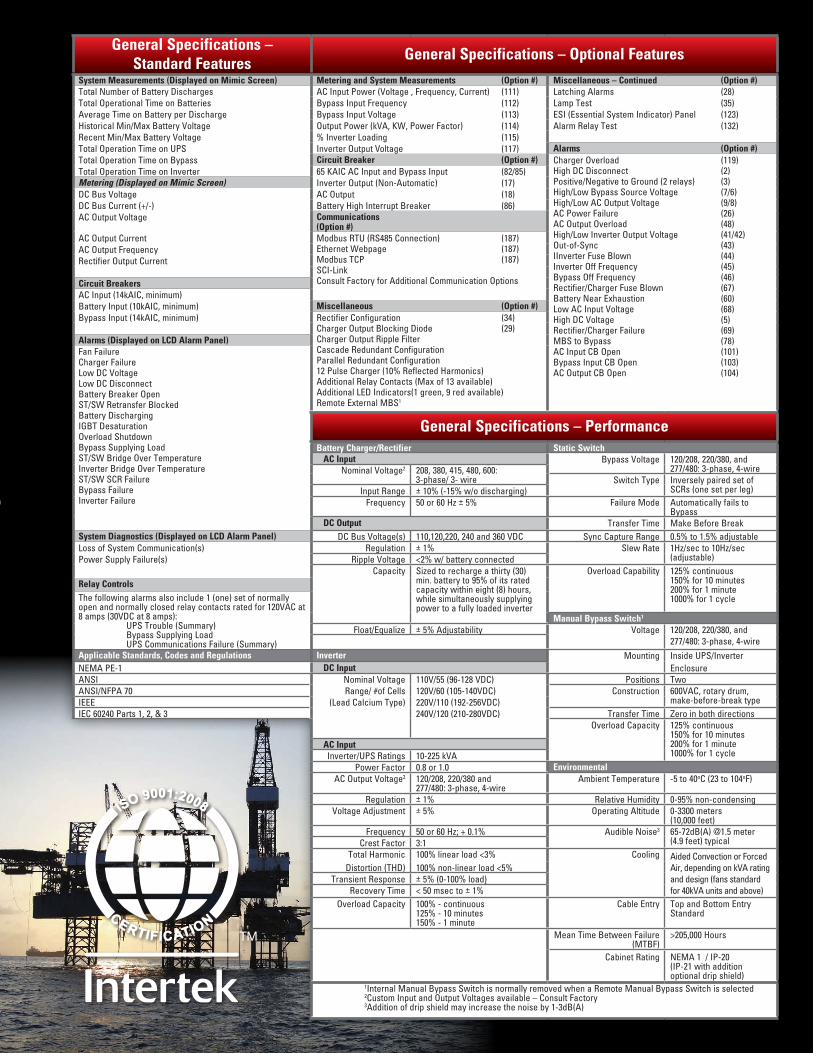
General Specifications – Standard Features
General Specifications – Optional Features
System Measurements (Displayed on Mimic Screen) Metering and System Measurements (Option #) Miscellaneous – Continued (Option #)Total Number of Battery Discharges AC Input Power (Voltage , Frequency, Current) (111) Latching Alarms (28)Total Operational Time on Batteries Bypass Input Frequency (112) Lamp Test (35)Average Time on Battery per Discharge Bypass Input Voltage (113) ESI (Essential System Indicator) Panel (123)Historical Min/Max Battery Voltage Output Power (kVA, KW, Power Factor) (114) Alarm Relay Test (132)Recent Min/Max Battery Voltage % Inverter Loading (115)Total Operation Time on UPS Inverter Output Voltage (117) Alarms (Option #)Total Operation Time on Bypass Circuit Breaker (Option #) Charger Overload (119)
High DC Disconnect (2)Positive/Negative to Ground (2 relays) (3)High/Low Bypass Source Voltage (7/6)High/Low AC Output Voltage (9/8)AC Power Failure (26)AC Output Overload (48)High/Low Inverter Output Voltage (41/42)Out-of-Sync (43)IInverter Fuse Blown (44)Inverter Off Frequency (45)Bypass Off Frequency (46)Rectifier/Charger Fuse Blown (67)Battery Near Exhaustion (60)Low AC Input Voltage (68)High DC Voltage (5)Rectifier/Charger Failure (69)MBS to Bypass (78)AC Input CB Open (101)Bypass Input CB Open (103)AC Output CB Open (104)
Total Operation Time on Inverter 65 KAIC AC Input and Bypass Input (82/85)Metering (Displayed on Mimic Screen) Inverter Output (Non-Automatic) (17)DC Bus Voltage AC Output (18)DC Bus Current (+/-) Battery High Interrupt Breaker (86)AC Output Voltage Communications
(Option #)AC Output Current Modbus RTU (RS485 Connection) (187)
Ethernet Webpage (187)Modbus TCP (187)SCI-Link Consult Factory for Additional Communication Options
AC Output FrequencyRectifier Output Current
Circuit BreakersAC Input (14kAIC, minimum)Battery Input (10kAIC, minimum) Miscellaneous (Option #)Bypass Input (14kAIC, minimum) Rectifier Configuration (34)
Charger Output Blocking Diode (29)Charger Output Ripple Filter Cascade Redundant ConfigurationParallel Redundant Configuration 12 Pulse Charger (10% Reflected Harmonics)Additional Relay Contacts (Max of 13 available)Additional LED Indicators(1 green, 9 red available)Remote External MBS1
Alarms (Displayed on LCD Alarm Panel)Fan FailureCharger FailureLow DC VoltageLow DC DisconnectBattery Breaker OpenST/SW Retransfer BlockedBattery DischargingIGBT DesaturationOverload ShutdownBypass Supplying LoadST/SW Bridge Over TemperatureInverter Bridge Over TemperatureST/SW SCR FailureBypass FailureInverter Failure
General Specifications – Performance Battery Charger/Rectifier Static Switch AC Input Bypass Voltage 120/208, 220/380, and
277/480: 3-phase, 4-wireNominal Voltage2 208, 380, 415, 480, 600: 3-phase/ 3- wire Switch Type Inversely paired set of
SCRs (one set per leg)Input Range ± 10% (-15% w/o discharging)Frequency 50 or 60 Hz ± 5% Failure Mode Automatically fails to
Bypass DC Output Transfer Time Make Before Break
System Diagnostics (Displayed on LCD Alarm Panel) DC Bus Voltage(s) 110,120,220, 240 and 360 VDC Sync Capture Range 0.5% to 1.5% adjustableLoss of System Communication(s) Regulation ± 1% Slew Rate 1Hz/sec to 10Hz/sec
(adjustable)Power Supply Failure(s) Ripple Voltage <2% w/ battery connectedCapacity Sized to recharge a thirty (30)
min. battery to 95% of its rated capacity within eight (8) hours, while simultaneously supplying power to a fully loaded inverter
Overload Capability 125% continuous 150% for 10 minutes200% for 1 minute1000% for 1 cycle
Relay ControlsThe following alarms also include 1 (one) set of normally open and normally closed relay contacts rated for 120VAC at 8 amps (30VDC at 8 amps): UPS Trouble (Summary) Bypass Supplying Load UPS Communications Failure (Summary)
Manual Bypass Switch1
Float/Equalize ± 5% Adjustability Voltage 120/208, 220/380, and277/480: 3-phase, 4-wire
Applicable Standards, Codes and Regulations Inverter Mounting Inside UPS/InverterNEMA PE-1 DC Input EnclosureANSI Nominal Voltage 110V/55 (96-128 VDC) Positions TwoANSI/NFPA 70 Range/ #of Cells 120V/60 (105-140VDC) Construction 600VAC, rotary drum,
make-before-break typeIEEE (Lead Calcium Type) 220V/110 (192-256VDC)IEC 60240 Parts 1, 2, & 3 240V/120 (210-280VDC) Transfer Time Zero in both directions
Overload Capacity 125% continuous 150% for 10 minutes 200% for 1 minute 1000% for 1 cycle
AC InputInverter/UPS Ratings 10-225 kVA
Power Factor 0.8 or 1.0 EnvironmentalAC Output Voltage2 120/208, 220/380 and
277/480: 3-phase, 4-wireAmbient Temperature -5 to 40oC (23 to 104oF)
Regulation ± 1% Relative Humidity 0-95% non-condensingVoltage Adjustment ± 5% Operating Altitude 0-3300 meters
(10,000 feet)Frequency 50 or 60 Hz; + 0.1% Audible Noise3 65-72dB(A) @1.5 meter
(4.9 feet) typicalCrest Factor 3:1Total Harmonic 100% linear load <3% Cooling Aided Convection or Forced
Distortion (THD) 100% non-linear load <5% Air, depending on kVA ratingTransient Response ± 5% (0-100% load) and design (fans standard
Recovery Time < 50 msec to ± 1% for 40kVA units and above)Overload Capacity 100% - continuous
125% - 10 minutes150% - 1 minute
Cable Entry Top and Bottom Entry Standard
Mean Time Between Failure (MTBF)
>205,000 Hours
Cabinet Rating NEMA 1 / IP-20(IP-21 with addition optional drip shield)
1Internal Manual Bypass Switch is normally removed when a Remote Manual Bypass Switch is selected2Custom Input and Output Voltages available – Consult Factory3Addition of drip shield may increase the noise by 1-3dB(A)

VISIT OUR WEBSITES:
English: www.solidstatecontrolsinc.com Nuclear: www.nuclearups.com
Spanish: www.solidstatecontrolsinc-esp.com
Russian: www.solidstatecontrolsinc-ru.com
Chinese: www.solidstatecontrolsinc-chn.com
Brazilian Portuguese: www.solidstatecontrolsinc-bz.com
All Facilities are ISO 9001 Certified
REV 1-12-2017
World Headquarters875 Dearborn Drive Columbus, Ohio 43085 Phone: +1-614-846-7500 Toll Free: +1-800-635-7300 Fax: +1-614-885-3990
Mexico HeadquartersCamino a la Montaña 178-101La Perla, Naucalpan Estado de México53340Phone: (55) 55250-1232Fax: (55) 5203-7981
Asia Pacific HeadquartersAMETEK Singapore Office 43 Changi South Ave. 2 #04-01 Singapore 486164 Phone: +65-6484-2388 Fax: +65-6481-6588
Brazil HeadquartersAMETEK do Brasil Ltda Rod. Eng° Ermênio de Oliveira Penteado (SP75) - Km 57, Barrio Tombadouro Indaiatuba - SP - Brasil, 13337-300 Phone: +55-16-2107-4100
Middle East OfficesDubaiP.O.Box 337164Office 2004 , X2 BuildingJumeirah Lakes Towers JLTDubai – UAEPhone: +971544300331 Saudi ArabiaKing Khalid Street, ATCO BuildingDammam, Saudi ArabiaPhone: +966 13 833 2339 ext. 654Direct: +966 830 5482Cell: +966 55 888 7860
India HeadquartersAMETEK Instruments India Private Limited Plot 148, EPIP Zone Phase 2 Featherlite Tech Park, 1st Floor Whitefield, Bangalore - 560066 Karnataka, INDIA Phone: +91 70222 53258 Fax: +91 80 6782 3232
Argentina HeadquartersOlive 1954Rosario 2000 – Sta Fe, ArgentinaPhone: +54 341 455 3332
THE PURPOSE OF OUR BUSINESS IS TO PROVIDE CONTINUITY OF ELECTRICAL POWER
TO KEEP BUSINESSES IN BUSINESS.