downstream technology solutions … technology solutions | products & services enhancing the ......
TRANSCRIPT

GE Oil & Gas
DOWNSTREAM TECHNOLOGY SOLUTIONS | PRODUCTS & SERVICES
Enhancing the design of hyper compressors and related LDPE plant components
Carmelo Maggi, GE Oil & GasLeonardo Tognarelli, GE Oil & GasStefano Giorgetti, GE Oil & Gas

AbstractEffective hyper compressor design depends heavily on a good understanding of all critical aspects of the LDPE plant. In addition, design-phase implementation must include identifying problems that may arise during plant operations and resolving them with appropriate technological solutions.
The first design stages are critical, and they concern the dynamic loads acting on the foundation, the torsional analysis involving the motor supplier, and the pulsation/vibration considerations that tie together the engineering company, the high-pressure equipment suppliers and the end users. All stress levels, pulsation and vibrations must be reduced, but those effects are influenced by the plant layout and the configuration of the compressor’s crankshaft cranks. While the configuration can improve the pulsation level, it also can affect the loads on the foundations.
Following is a look at how some technical aspects of the plant can be designed to enhance plant operations.
2Enhancing the design of hyper compressors and related LDPE plant components
Nomenclature
API American Petroleum Institute
ASME American Society of Mechanical Engineers
ACI American Concrete Institute
BS British Standard
FEM Finite Element Method
LDPE Low Density Poly Ethylene
P&ID Piping & Instrumentation Diagram
RPM Revolutions per Minute
IntroductionAn LDPE plant requires huge heavy-duty reciprocating compressors to withstand the loads that result from operating pressures. Safety, performance, reliability and maintainability are the most important targets to achieve for the greatest possible plant availability.
The preliminary selection of a machine begins with a positive experience in similar applications, but the machine then must be customized to meet specific requirements. While each configuration has unique elements, there are some key common aspects that guide the design of all plants. Typically, the LDPE plant has different arrangements, including a booster, a primary and a hyper compressor.
The sizing of the compressors is driven by the plant capacity and process operating conditions, and achieved by determining the most effective number and size of the cylinders. The pulsation and vibration of the piping are usually investigated to keep the plant operating without failures and, depending on the operating conditions, the number of cylinders and arrangement of related piping.
Even the torsional aspects of the train (compressor and driver), must be examined to avoid potential resonances that otherwise may be caused by the crankshaft design and external loads.
It’s also necessary to address compressor-generated vibrations during the design phase to avoid unexpected compressor alarms or trips and/or foundation issues.
To effectively handle the high operating pressures that produce high operating loads, all of the above factors must be considered in the initial engineering stage for hyper compressors (Figure 1). Therefore, it’s only possible to obtain peak hyper compressor performance with a careful design of the crankshaft that accounts for the number of cylinders.
Balancing of hyper compressorsHyper compressors [8] are special reciprocating compressors designed to compress the gas up to 350 MPa [7].
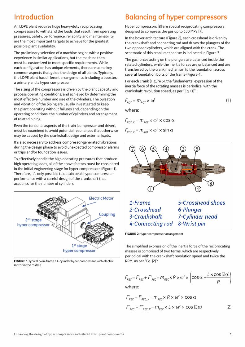
In the boxer architecture (Figure 2), each crosshead is driven by the crankshaft and connecting rod and drives the plungers of the two opposed cylinders, which are aligned with the crank. The schematic of this crank mechanism is indicated in Figure 3.
The gas forces acting on the plungers are balanced inside the related cylinders, while the inertia forces are unbalanced and are transferred by the crank mechanism to the foundation across several foundation bolts of the frame (Figure 4).
For each crank (Figure 3), the fundamental expression of the inertia force of the rotating masses is periodical with the crankshaft revolution speed, as per “Eq. (1)”:
The simplified expression of the inertia force of the reciprocating masses is comprised of two terms, which are respectively periodical with the crankshaft revolution speed and twice the RPM, as per “Eq. (2)”:
(1)
where:
FROT = mROT × ω2
FROT, X = mROT × ω2 × cos α
FROT, Z = mROT × ω2 × sin α
( )R
L × cos (2α)
(2)
FREC = F'REC + F"REC = mREC × R × ω2 × cos α +
F'REC = F'REC, X = mREC × R × ω2 × cos α
F"REC = F"REC, X = mREC × L × ω2 × cos (2α)
where:
FIGURE 1 Typical twin-frame 14-cylinder hyper compressor with electric motor in the middle
FIGURE 2 Hyper compressor arrangement
3Enhancing the design of hyper compressors and related LDPE plant components

In addition to the above forces projected in X and Z directions, Figure 4 shows the vertical force T, caused by the obliquity of the connecting rod, that is balanced by the couple Cy of the foundation. Usually this force is negligible compared to the horizontal and vertical inertia forces, and it does not need to be considered.
Figure 5 indicates the trend of the inertia forces in function of the crank angle a.
All of the above considerations are for each crank that involves two opposite cylinders. When the crankshaft of
the hyper compressor is comprised of two or more cranks, the combination of the inertia forces of each crank, expressed as a sum in amplitude and phases, generates additional couples Cx and Cz, parallel to the X and Z axes (Figure 6).
For crankshafts having two or more cranks, the designer’s first task is to balance, if possible, the overall inertia forces across appropriate angular phases to obtain equally spaced cranks (Figure 7). The next step is to evaluate the inertia moments generated by the inertia forces that result from the distance between the cranks.
FIGURE 3 Crank mechanism
FIGURE 4 Forces and couples transferred to the foundation for each crank
FIGURE 5 Trend of the inertia forces
FIGURE 6 Scheme of hyper compressor twin frames with the electric motor in the middle
FIGURE 7 Typical crankshaft layouts
4Enhancing the design of hyper compressors and related LDPE plant components
The balancing of the total inertia moment is more complex than the balancing of the inertia forces and is dependent on the number of cranks of the crankshaft. With a low number of cranks, it’s not possible to balance the total moment of inertia without affecting the balancing of the inertia forces.
To achieve that balance, it’s necessary to greatly reduce the total moment of inertia by rearranging the cranks’ position and maintaining the crank angles that previously had been obtained to balance the total inertia forces (except the shaft with two cranks).
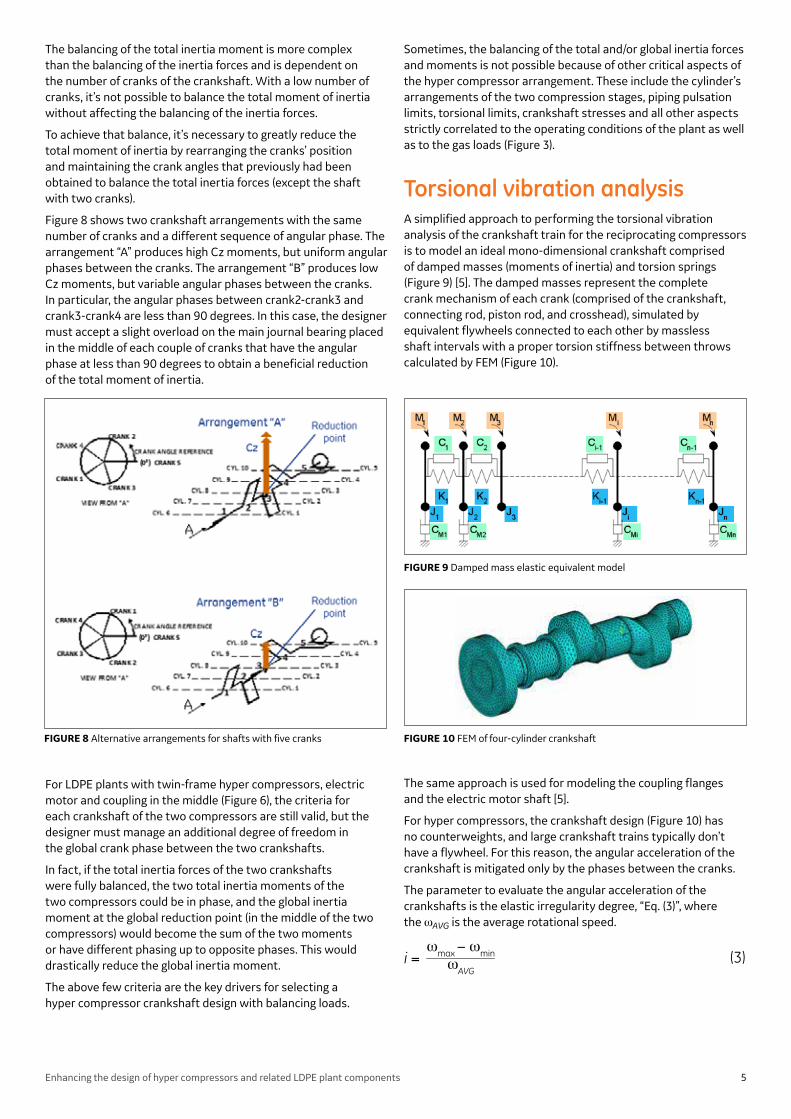
Figure 8 shows two crankshaft arrangements with the same number of cranks and a different sequence of angular phase. The arrangement “A” produces high Cz moments, but uniform angular phases between the cranks. The arrangement “B” produces low Cz moments, but variable angular phases between the cranks. In particular, the angular phases between crank2-crank3 and crank3-crank4 are less than 90 degrees. In this case, the designer must accept a slight overload on the main journal bearing placed in the middle of each couple of cranks that have the angular phase at less than 90 degrees to obtain a beneficial reduction of the total moment of inertia.
For LDPE plants with twin-frame hyper compressors, electric motor and coupling in the middle (Figure 6), the criteria for each crankshaft of the two compressors are still valid, but the designer must manage an additional degree of freedom in the global crank phase between the two crankshafts.
In fact, if the total inertia forces of the two crankshafts were fully balanced, the two total inertia moments of the two compressors could be in phase, and the global inertia moment at the global reduction point (in the middle of the two compressors) would become the sum of the two moments or have different phasing up to opposite phases. This would drastically reduce the global inertia moment.
The above few criteria are the key drivers for selecting a hyper compressor crankshaft design with balancing loads.
Sometimes, the balancing of the total and/or global inertia forces and moments is not possible because of other critical aspects of the hyper compressor arrangement. These include the cylinder’s arrangements of the two compression stages, piping pulsation limits, torsional limits, crankshaft stresses and all other aspects strictly correlated to the operating conditions of the plant as well as to the gas loads (Figure 3).
Torsional vibration analysis A simplified approach to performing the torsional vibration analysis of the crankshaft train for the reciprocating compressors is to model an ideal mono-dimensional crankshaft comprised of damped masses (moments of inertia) and torsion springs (Figure 9) [5]. The damped masses represent the complete crank mechanism of each crank (comprised of the crankshaft, connecting rod, piston rod, and crosshead), simulated by equivalent flywheels connected to each other by massless shaft intervals with a proper torsion stiffness between throws calculated by FEM (Figure 10).
The same approach is used for modeling the coupling flanges and the electric motor shaft [5].
For hyper compressors, the crankshaft design (Figure 10) has no counterweights, and large crankshaft trains typically don’t have a flywheel. For this reason, the angular acceleration of the crankshaft is mitigated only by the phases between the cranks.
The parameter to evaluate the angular acceleration of the crankshafts is the elastic irregularity degree, “Eq. (3)”, where the ωAVG is the average rotational speed.
i = ωmax − ωmin
ωAVG(3)
FIGURE 8 Alternative arrangements for shafts with five cranks
FIGURE 9 Damped mass elastic equivalent model
FIGURE 10 FEM of four-cylinder crankshaft
5Enhancing the design of hyper compressors and related LDPE plant components
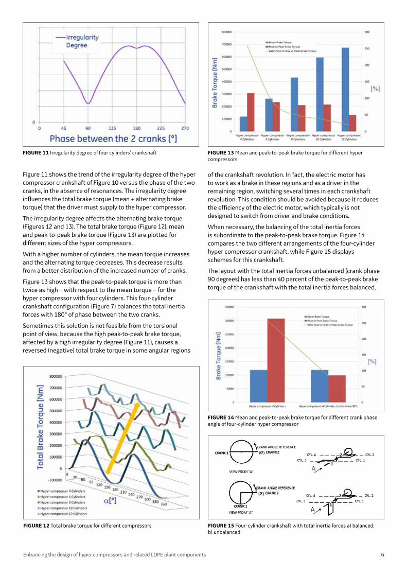
Figure 11 shows the trend of the irregularity degree of the hyper compressor crankshaft of Figure 10 versus the phase of the two cranks, in the absence of resonances. The irregularity degree influences the total brake torque (mean + alternating brake torque) that the driver must supply to the hyper compressor.
The irregularity degree affects the alternating brake torque (Figures 12 and 13). The total brake torque (Figure 12), mean and peak-to-peak brake torque (Figure 13) are plotted for different sizes of the hyper compressors.
With a higher number of cylinders, the mean torque increases and the alternating torque decreases. This decrease results from a better distribution of the increased number of cranks.
Figure 13 shows that the peak-to-peak torque is more than twice as high – with respect to the mean torque – for the hyper compressor with four cylinders. This four-cylinder crankshaft configuration (Figure 7) balances the total inertia forces with 180° of phase between the two cranks.
Sometimes this solution is not feasible from the torsional point of view, because the high peak-to-peak brake torque, affected by a high irregularity degree (Figure 11), causes a reversed (negative) total brake torque in some angular regions
of the crankshaft revolution. In fact, the electric motor has to work as a brake in these regions and as a driver in the remaining region, switching several times in each crankshaft revolution. This condition should be avoided because it reduces the efficiency of the electric motor, which typically is not designed to switch from driver and brake conditions.
When necessary, the balancing of the total inertia forces is subordinate to the peak-to-peak brake torque. Figure 14 compares the two different arrangements of the four-cylinder hyper compressor crankshaft, while Figure 15 displays schemes for this crankshaft.
The layout with the total inertia forces unbalanced (crank phase 90 degrees) has less than 40 percent of the peak-to-peak brake torque of the crankshaft with the total inertia forces balanced.
FIGURE 11 Irregularity degree of four cylinders’ crankshaft
FIGURE 12 Total brake torque for different compressors
FIGURE 13 Mean and peak-to-peak brake torque for different hyper compressors
FIGURE 14 Mean and peak-to-peak brake torque for different crank phase angle of four-cylinder hyper compressor
FIGURE 15 Four-cylinder crankshaft with total inertia forces a) balanced; b) unbalanced
6Enhancing the design of hyper compressors and related LDPE plant components
Pressure pulsation and vibration On LDPE plants, the booster-primary and hyper compressor generate an unsteady flow on the gas piping, connected to the cylinders, that generates pressure pulsations inside the piping, and their operation can be subjected to severe vibrations [3].
For the booster-primary, the design of the pulsation suppression devices (volume bottles or dampeners) that are close to the cylinders can significantly reduce the pressure pulsation on the following piping [2].
Extreme operating pressure (well beyond the scope of API 618), and high construction costs (because of the high walls’ thickness and autofrettage treatment needed for manufacturing), make the use of acoustic filters such as the volume bottle unsuitable for the hyper compressor [1][4].
The unsteady gas flow coming from the cylinders is directly transferred to the piping and from there to the reactor. For this reason, an accurate design requires several analyses of the high-pressure piping [4]. In fact, the pressure pulsation produces fatigue stresses on the piping that require a special process, the autofrettage, to decrease the overall stresses at the inner diameter. This pressure pulsation also induces shaking forces on the piping at each elbow (Figure 16) and potential acoustical resonances caused by the reflection of the pulsating gas waves along the path of the entire piping. This is mainly due to the presence of elbows (changing direction of the flow) and the reduction or increase of the piping inner diameter [3].
The shaking forces and the acoustical resonances can be controlled with the proper dimensioning of the piping design, the introduction of the orifices in proper locations, and the correct dimensioning of the piping supports.
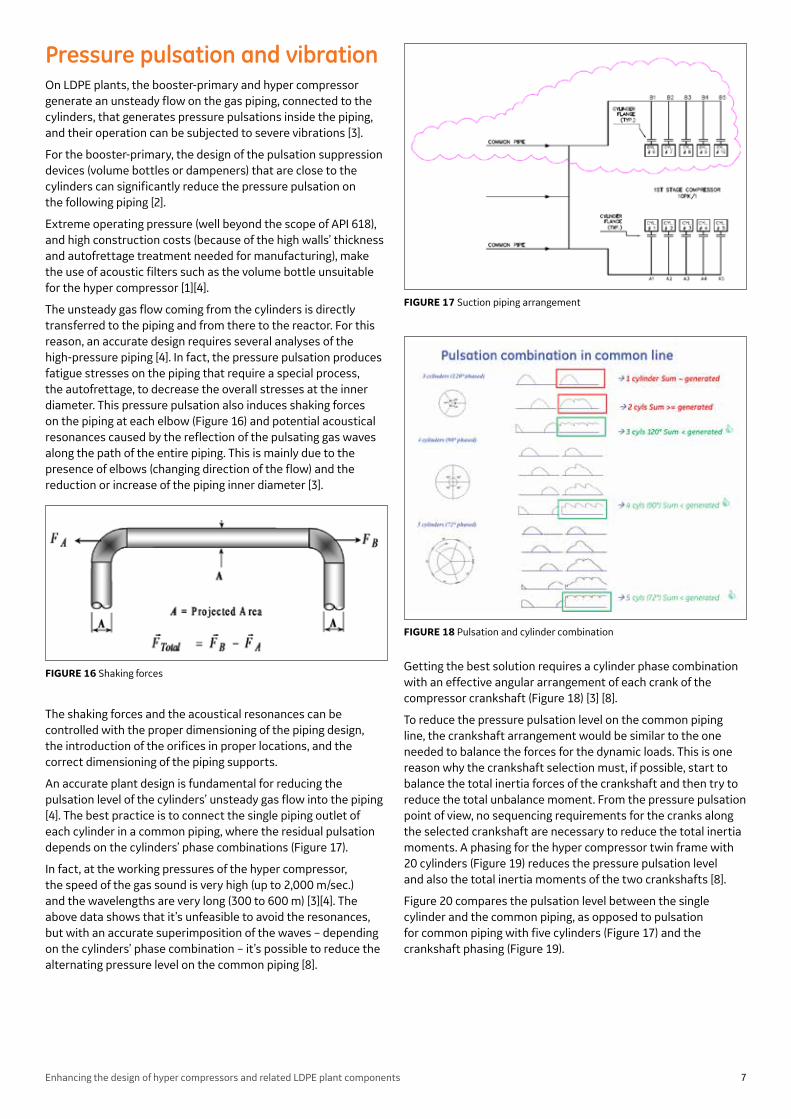
An accurate plant design is fundamental for reducing the pulsation level of the cylinders’ unsteady gas flow into the piping [4]. The best practice is to connect the single piping outlet of each cylinder in a common piping, where the residual pulsation depends on the cylinders’ phase combinations (Figure 17).
In fact, at the working pressures of the hyper compressor, the speed of the gas sound is very high (up to 2,000 m/sec.) and the wavelengths are very long (300 to 600 m) [3][4]. The above data shows that it’s unfeasible to avoid the resonances, but with an accurate superimposition of the waves – depending on the cylinders’ phase combination – it’s possible to reduce the alternating pressure level on the common piping [8].
Getting the best solution requires a cylinder phase combination with an effective angular arrangement of each crank of the compressor crankshaft (Figure 18) [3] [8].
To reduce the pressure pulsation level on the common piping line, the crankshaft arrangement would be similar to the one needed to balance the forces for the dynamic loads. This is one reason why the crankshaft selection must, if possible, start to balance the total inertia forces of the crankshaft and then try to reduce the total unbalance moment. From the pressure pulsation point of view, no sequencing requirements for the cranks along the selected crankshaft are necessary to reduce the total inertia moments. A phasing for the hyper compressor twin frame with 20 cylinders (Figure 19) reduces the pressure pulsation level and also the total inertia moments of the two crankshafts [8].
Figure 20 compares the pulsation level between the single cylinder and the common piping, as opposed to pulsation for common piping with five cylinders (Figure 17) and the crankshaft phasing (Figure 19).
FIGURE 17 Suction piping arrangement
FIGURE 16 Shaking forces
FIGURE 18 Pulsation and cylinder combination
7Enhancing the design of hyper compressors and related LDPE plant components

FoundationsThe foundation basement of the compressors can be:
• A solid block with piping and equipment that creates a more robust solution and easier maintenance for the various pieces of equipment, since the space around is wider (shallow foundation).
• Similar to a table with a more compact solution, where the high-pressure piping can be positioned under the compressor (table top foundation). In this case, the lower stiffness creates a greater possibility of vibration, so the balancing of inertial forces and dynamic loads must be evaluated more carefully.
The foundation normally is controlled by the engineering companies and designed for ruggedness and the prevention of dangerous vibrations arising from the dynamic loads.
The dynamic design drives the block dimensioning; displacement over the compressor manufacturer specification shall be taken under the limit values, if possible, out of the frequency level that is dangerous for the reciprocating machinery.
Crank phasing to reduce foundation loadsEven if efficiency is the top priority, reciprocating compressor designers must carefully consider what loads the machine configuration produces on the foundation, since these can change significantly, depending on the different crank phase.
It’s necessary to consider the dimensioning of the entire model comprised of the machinery foundation block and the ground beneath it. This analysis should be done at the beginning of the project and account for a range of soils to lessen the risk that the installed machinery wouldn’t be well sustained dynamically by poor soil.
The foundation site where the reciprocating compressors are installed can be:
• In a greenfield where the foundation block is new
• In a brownfield where the foundation block is already installed and part of the foundation block will be built for the revamping or reinstallation of machinery. In this case the civil designer would adjust the shape according to the existing foundation’s geometries and other equipment positions
A typical configuration for hyper compressors has twin frame compressors and an electric motor in the middle. The foundation loads are applied to correspond to the center of gravity of each machine (origin of the Cartesian coordinate system) (Figure 21).
For the calculation model, the masses of machines and dynamic action are transferred to relevant nodes on the block (anchoring points) by rigid link elements (Figure 21).
FIGURE 19 Crankshaft phasing
FIGURE 20 Comparison of pressure pulsation level
FIGURE 21 Twin-frame hyper compressor foundation model
8Enhancing the design of hyper compressors and related LDPE plant components

Loads variance with different crankshaft phasingDifferent phasing of the cranks in the shafts generates different loads on the foundation.
The foundation of a twin-frame hyper compressor has been modeled (Figure 21), and for three different crankshafts configurations (Figures 22a, 23a, 24a) the corresponding loads on the foundation have been calculated (Figures 22b, 23b, 24b) to reflect changes in the internal and external crank phasing. To represent the loads on a graph, each load component is presented in the following 1st order equations (“Eq.(4)” - “Eq.(7)”):
The main axial forces can be reduced significantly (by about 30 percent) by switching from “Int ph.=90°/Ext ph.0” (Figure 22a, b) or “Int ph.=90°/ Ext ph.180°” (Figures 23a, b)” to “Int ph.=120°/ Ext ph.180” (Figures 24a, b). This last phasing greatly benefits the foundation design.
The type of loading can significantly impact foundation design. Special care must be taken to distinguish between and handle horizontal or torque moments (rotation of the moment in the horizontal plane) and vertical or rocking moments (rotation of the moment around the longitudinal axis of the machinery) (Figure 25), since they imply different requirements for the foundations that need to contrast these loads.
For horizontal or torque moments that act on the foundation’s horizontal plan, the contrast will be in the friction of the ground beneath the block, where the resultant of the friction force shall be greater that the torque moment applied. Standard Codes and Practices like BS and ACI give proper guidance for correct calculation and dimensioning.
The vertical or rocking moment, acting around the longitudinal axis, will be contrasted by the foundation vertical section, which will be robust enough to fight this moment. The reinforced concrete must have suitable inertia for opposing this action, and the pressure transferred on the soil must be below allowable soil characteristic values. This last condition is the hardest to sustain, because the soil can respond differently under a static pressure or dynamic loads. Therefore, reducing the rocking moment through crankshaft phasing is particularly critical.
• Horizontal/Vertical Forces Hi' = Hi *cos (ω*t-φHi ) Vi' = Vi *cos (ω*t-φVi )
• Horizontal/Vertical Moments MHI' = MHI *cos (ω*t-φMHi ) MVI' = MVI *cos (ω*t-φMVi )
where:
i = 1 (for 4 cylinders stage 1) or 2 (for 4 cylinders stage 2)
ω = angular speed [rad] Hi ,Vi = Amplitude of Forces [daN] MHi = Amplitude of Moments [daN*m]
φ... = phase [rad]
(4)
(5)
(6)
(7)
a
FIGURE 22 a) Phasing case 1: Int. = 90°/Ext.0°; b) Foundation loads
b
9Enhancing the design of hyper compressors and related LDPE plant components

Dynamic behavior of the foundationThe dynamic behavior of the foundation is even more important than static behavior, since foundations can respond to the excitation of the variable loads produced by hyper compressors at specific frequencies with quite large amplification factors. This can significantly influence the displacement values so that they hamper the operation of the machinery.
The amplification factors are a function of the exciting frequency, natural frequency and damping ratio D as shown in “Eq. (8)”:
1
( )f 2
fn( )f 2
fn
A =
+ 4 · D2 · 1 – (8)2
Soil damping is the ratio of actual damping/soil critical damping D = C/Ccrit where C is the damping coefficient of each vibration mode and Ccrit- is the soil critical damping which in turn is correlated to other soil characteristics.
As required by the manufacturer, the civil design will avoid the dangerous ranges around the operational frequency (+/- 30 percent usually) and the other potential excitation frequencies (higher order harmonics).
The harmonic analysis will explore the vibrational behavior of the machinery block at the different main frequencies, taking into account that the amplification factor can significantly increase the displacement of the block, especially when the system’s natural frequencies are close to the machine’s operational frequencies.
a
FIGURE 24 a) Phasing 3: Int.120°/Ext.180°; b) Foundation loads
b
a
FIGURE 23 a) Phasing 2: Int.90°/ Ext.180°; b) Foundation loads
b
FIGURE 25 Horizontal and vertical moments on foundations
10Enhancing the design of hyper compressors and related LDPE plant components

Conclusions LPDE production requires processing equipment with increased capacities and an existing application uprating.
An integrated plant design must pay special attention to safety and reliability, since those are the key factors for end user and supplier success.
Designing the most effectively performing overall plant requires a proper balance among all critical elements, i.e., hyper compressor crankshaft configuration, angle phasing between shafts, train torsional analysis, foundation design, and impacts on pressure pulsation and piping vibration. Such an approach also requires a tight collaboration among all involved parties (manufacturers, engineering contractor, end user and licensor) right from the start. This cooperation – covering agreement on customer P&IDs in the bidding phase, on plant piping layout, and on actual operating conditions – will correctly drive the design of the plant’s compressor and associated equipment. This approach reduces the risk of a design modification in an advanced phase of the project, increases plant reliability and efficiency, and reduces plant maintenance costs.
References1 Possamai, F.C. and M.L. Todescat, 2004, “A review of household
compressor energy performance,” Int. Compressor Engineering Conference, Purdue University, Indiana.
2 API 618 STD fourth ed., June 1995, “Reciprocating Compressor for Petroleum, Chemical and gas Industry services” American Petroleum institute. pp. 37-42 and 147-148)
3 ASME - Boiler and Pressure Vessel code, sect. VIII Div. 2, 2001, The American Society of Mechanical Engineers
4 Giacomelli E., Passeri M., Bassani S., Zagli F., Pieraccini M.,” Preliminary Pulsation Analysis for High Pressure Piping Size Evaluation for Hyper-Compressor for LDPE Plants”, PVP2006-ICPVT11-93234, Proceedings of PVP 2006:Pressure Vessels and Piping 23-27 July 2006, Vancouver, BC, Canada
5 Giacomelli E., Passeri M., Giusti S., Zagli F., Generosi S., 2004, ”Modeling of Pressure Pulsations for Reciprocating Compressors and Interaction with Mechanical System”, Proceedings of ESDA, Engineering System Design and Analysis, 19-22 July, Manchester, UK, The American Society of Mechanical Engineers.
6 Giacomelli E., Mazzali C., Falciani F., Battagli P., “Torsional Analysis of a 20 Cylinder Hyper-compressor Train”, ESDA2006-95503, Proceedings of ESDA 2006:Engineering System Design and Analysis, 4-7 July 2006, Torino, Italy
7 Giacomelli E., Passeri M., Zagli F., Generosi S., 2004, “Control of Pulsations and Vibrations in Hyper-compressors for LDPE Plants”, PVP-Vol.473, High Pressure Technology-Innovations and Advances on High Pressure Technology, July 25-29,2004,San Diego, California, USA, PVP2004-2281
8 Giacomelli E., Traversari A., 2001, “Very High Pressure Compressors (over 100 MPa) [14500psi]”, 2001, Compressor Handbook, Paul C. Hanlon Editor, McGraw-Hill, NY 2001
9 Passeri M., Generosi S., Bagagli R., Maggi C. Proceedings of ASME PVP 2014 Pressure Vessels & Piping Conference PVP 2014 July 20-24, 2014, Anaheim, California, USA
11Enhancing the design of hyper compressors and related LDPE plant components
Imagination at work
GE Oil & Gas - Global Headquarters The Ark - 201 Talgarth Road, Hammersmith - London, W6 8BJ, UK T +44 207 302 6000 [email protected]
Nuovo Pignone S.p.A. - Nuovo Pignone S.r.l Via Felice Matteucci, 2 - 50127 Florence, Italy T +39 055 423 211 F +39 055 423 2800
Downstream Technology Solutions 4424 West Sam Houston Parkway North - Houston, TX 77041-8200, US
Reciprocating compressor cylinder’s cooling: a numerical approach using computational fluid dynamics with conjugate heat transfer
By Carmelo Maggi, Leonardo Tognarelli, Stefano Giorgetti
© PVP 2015-45185 ASME
GEA32031 (08/2015)