Download - Zircon Programmer’s Manual V2

Zircon Programmer’s Manual V2.32
An RF tester for the Bluetooth® 5 BR/EDR standard, compatible with TLF3000.
27 January 2022

TELEDYNE LECROY
2 TLF3000 Zircon Programmer’s Manual V2.32
1 Contents
1 Contents ................................................................................................................................................ 2
2 Overview. .............................................................................................................................................. 9
3 Modes of Operation. ........................................................................................................................... 10
3.1 Overview ..................................................................................................................................... 10
4 Phy Level Tester Mode ........................................................................................................................ 11
4.1 Overview ..................................................................................................................................... 11
4.1.1 Supported tests ................................................................................................................... 11
4.1.2 Scripting .............................................................................................................................. 12
4.1.3 Parameter searches ............................................................................................................ 13
4.1.4 External Connectivity .......................................................................................................... 13
4.2 Signal Generator Mode ............................................................................................................... 14
4.2.1 Overview ............................................................................................................................. 14
4.2.2 Wanted signal ..................................................................................................................... 14
4.2.3 Interfering signal ................................................................................................................. 15
4.2.4 Primary and Seconadry In-band CW signals ....................................................................... 16
4.2.5 AWGN signal ....................................................................................................................... 16
4.2.6 Out-of-band CW signal ........................................................................................................ 16
4.3 Signal Analyser Mode .................................................................................................................. 17
4.3.1 Overview ............................................................................................................................. 17
4.3.2 Capture port ........................................................................................................................ 17
5 Python Interface ................................................................................................................................. 18
5.1 Overview ..................................................................................................................................... 18
5.1.1 Prerequistes ........................................................................................................................ 18
5.1.2 Connecting to the TLF3000 ................................................................................................. 18
5.1.3 Launching the Zircon application ........................................................................................ 19
5.1.4 Handling asynchronouos data ............................................................................................ 20
5.1.5 Handling errors ................................................................................................................... 21
5.1.6 Closing down ....................................................................................................................... 21
5.2 Examples ..................................................................................................................................... 22
5.2.1 Running a phy test script .................................................................................................... 22

TELEDYNE LECROY
3 TLF3000 Zircon Programmer’s Manual V2.32
5.2.1.1 Inquiry and connection callbacks .................................................................................... 26
5.2.1.2 Test progress ................................................................................................................... 27
5.2.1.3 Tables for decoding results ............................................................................................. 28
5.2.1.4 Common routines ........................................................................................................... 28
5.2.1.5 Transtmitter test results ................................................................................................. 30
5.2.1.6 Receiver test results ........................................................................................................ 47
5.2.2 Programming the signal generator ..................................................................................... 52
5.2.2.1 Completion of transmission of wanted signal ................................................................ 57
5.2.3 Analysing waveforms using the signal analyser .................................................................. 58
5.2.4 Controlling a DUT over-the-air ............................................................................................ 67
5.2.5 Making measurements on a CW signal ............................................................................... 71
5.3 Library reference ......................................................................................................................... 73
5.3.1 Overview ............................................................................................................................. 73
5.3.2 setMode .............................................................................................................................. 73
5.3.3 startScript ............................................................................................................................ 73
5.3.4 contScript ............................................................................................................................ 74
5.3.5 endScript ............................................................................................................................. 74
5.3.6 deleteScript ......................................................................................................................... 74
5.3.7 runScript .............................................................................................................................. 75
5.3.8 abortScript .......................................................................................................................... 76
5.3.9 setCableLoss ........................................................................................................................ 76
5.3.10 setCableLosses .................................................................................................................... 76
5.3.11 progWanted ........................................................................................................................ 77
5.3.12 progInterferer ..................................................................................................................... 80
5.3.13 progCW ............................................................................................................................... 80
5.3.14 progAWGN .......................................................................................................................... 81
5.3.15 progOutOfBandCW ............................................................................................................. 81
5.3.16 startSigGen .......................................................................................................................... 82
5.3.17 stopSigGen .......................................................................................................................... 82
5.3.18 startSigAna .......................................................................................................................... 82
5.3.19 stopSigAna .......................................................................................................................... 82
5.3.20 pollSigAnaTable ................................................................................................................... 83

TELEDYNE LECROY
4 TLF3000 Zircon Programmer’s Manual V2.32
5.3.21 pollResultsPlot .................................................................................................................... 86
5.3.22 getResultsPlotFloat ............................................................................................................. 94
5.3.23 clearResults ......................................................................................................................... 94
5.3.24 setLimits .............................................................................................................................. 94
5.3.25 doInquiry ............................................................................................................................. 96
5.3.26 doPage ................................................................................................................................ 97
5.3.27 progLoopback ...................................................................................................................... 97
5.3.28 pwrControl .......................................................................................................................... 99
5.3.29 setPollPwr ........................................................................................................................... 99
5.3.30 setLoopPwr ......................................................................................................................... 99
5.3.31 setRSSIthreshold ............................................................................................................... 100
5.3.32 doStopOnFail ..................................................................................................................... 100
5.3.33 loadDirtyTx ........................................................................................................................ 100
5.3.34 IgnoreExceptions ............................................................................................................... 101
5.3.35 setRxAtten ......................................................................................................................... 101
5.3.36 getRxAtten ........................................................................................................................ 101
5.3.37 setRxPort ........................................................................................................................... 101
5.3.38 getRxPort ........................................................................................................................... 102
5.3.39 setDIOVolts ....................................................................................................................... 102
5.3.40 getError ............................................................................................................................. 102
5.3.41 exitApp .............................................................................................................................. 103
5.3.42 measCW ............................................................................................................................ 103
5.3.43 hardwareReset .................................................................................................................. 103
5.3.44 powerDown ....................................................................................................................... 103
5.3.45 getFriendlyName ............................................................................................................... 103
5.3.46 getSerialNumber ............................................................................................................... 103
5.3.47 stashExe ............................................................................................................................ 104
5.3.48 swapExe ............................................................................................................................ 104
5.3.49 suspend ............................................................................................................................. 104
5.3.50 resume .............................................................................................................................. 104
6 C dll Interface .................................................................................................................................... 105
6.1 Overview ................................................................................................................................... 105

TELEDYNE LECROY
5 TLF3000 Zircon Programmer’s Manual V2.32
6.1.1 Connecting to the TLF3000 ............................................................................................... 105
6.1.2 Handling asynchronous data ............................................................................................. 105
6.1.3 Handling errors ................................................................................................................. 106
6.1.4 Closing down ..................................................................................................................... 106
6.1.5 Switching between applications on the TLF3000 ............................................................. 107
6.2 Examples ................................................................................................................................... 108
6.2.1 Running a phy test script .................................................................................................. 108
6.2.1.1 Inquiry and associated callbacks ................................................................................... 113
6.2.1.2 Test progress ................................................................................................................. 114
6.2.1.3 Tables for decoding results ........................................................................................... 115
6.2.1.4 Common routines ......................................................................................................... 116
6.2.1.5 Transtmitter test results ............................................................................................... 117
6.2.1.6 Receiver test results ...................................................................................................... 137
6.2.2 Programming the signal generator ................................................................................... 144
6.2.2.1 Completion of transmission of wanted signal .............................................................. 151
6.2.3 Analysing waveforms using the signal analyser ................................................................ 152
6.2.4 Controlling a DUT over-the-air .......................................................................................... 161
6.2.5 Simplied phy test report generation ................................................................................. 167
6.2.6 Measuring a CW signal ...................................................................................................... 169
6.3 Library reference ....................................................................................................................... 172
6.3.1 Overview ........................................................................................................................... 172
6.3.2 zircon_setMode ................................................................................................................ 172
6.3.3 zircon_startScript .............................................................................................................. 172
6.3.4 zircon_contScript .............................................................................................................. 173
6.3.5 zircon_endScript ............................................................................................................... 173
6.3.6 zircon_deleteScript ........................................................................................................... 173
6.3.7 zircon_runScript ................................................................................................................ 174
6.3.8 zircon_runScript2 .............................................................................................................. 175
6.3.9 zircon_abortScript ............................................................................................................. 176
6.3.10 zircon_setCableLoss .......................................................................................................... 176
6.3.11 zircon_setCableLosses ...................................................................................................... 177
6.3.12 zircon_progWanted .......................................................................................................... 177

TELEDYNE LECROY
6 TLF3000 Zircon Programmer’s Manual V2.32
6.3.13 zircon_progInterferer ........................................................................................................ 181
6.3.14 zircon_progCW .................................................................................................................. 182
6.3.15 zircon_progAWGN ............................................................................................................ 182
6.3.16 zircon_progOutOfBandCW ............................................................................................... 182
6.3.17 zircon_startSigGen ............................................................................................................ 183
6.3.18 zircon_stopSigGen ............................................................................................................ 183
6.3.19 zircon_startSigAna ............................................................................................................ 183
6.3.20 Zircon_stopSigAna ............................................................................................................ 184
6.3.21 zircon_pollResultsTable .................................................................................................... 184
6.3.22 zircon_pollResultsPlot ....................................................................................................... 188
6.3.23 zircon_getResultsPlotFloat ............................................................................................... 195
6.3.24 zircon_clearResults ........................................................................................................... 196
6.3.25 zircon_setLimits ................................................................................................................ 196
6.3.26 zircon_inquiry ................................................................................................................... 197
6.3.27 zircon_page ....................................................................................................................... 198
6.3.28 zircon_loopback ................................................................................................................ 199
6.3.29 zircon_pwrControl ............................................................................................................ 200
6.3.30 zircon_pollPwr .................................................................................................................. 200
6.3.31 zircon_loopPwr ................................................................................................................. 201
6.3.32 zircon_rssiThreshold ......................................................................................................... 201
6.3.33 zircon_stopOnFail ............................................................................................................. 201
6.3.34 zircon_loadDirtyTx ............................................................................................................ 201
6.3.35 zircon_ignoreExceptions ................................................................................................... 202
6.3.36 zircon_setRxAtten ............................................................................................................. 202
6.3.37 zircon_setRxPort ............................................................................................................... 202
6.3.38 zircon_setDIOVolts ............................................................................................................ 203
6.3.39 zircon_getError ................................................................................................................. 203
6.3.40 zircon_search .................................................................................................................... 203
6.3.41 zircon_connect .................................................................................................................. 204
6.3.42 zircon_disconnect ............................................................................................................. 204
6.3.43 zircon_search_simple........................................................................................................ 204
6.3.44 zircon_search_result ......................................................................................................... 204
TELEDYNE LECROY
7 TLF3000 Zircon Programmer’s Manual V2.32
6.3.45 zircon_free_search_results ............................................................................................... 204
6.3.46 zircon_connect_serial ....................................................................................................... 205
6.3.47 zircon_destroy................................................................................................................... 205
6.3.48 zircon_setDataCallback ..................................................................................................... 205
6.3.49 zircon_measure_cw .......................................................................................................... 205
6.3.50 zircon_testWrapper .......................................................................................................... 206
6.3.51 zircon_testWrapperScalar................................................................................................. 207
6.3.52 zircon_testWrapper2 ........................................................................................................ 208
6.3.53 zircon_testWrapperScalar2 .............................................................................................. 211
6.3.54 zircon_testWrapper_CW................................................................................................... 212
6.3.55 zircon_hardwareReset ...................................................................................................... 213
6.3.56 zircon_powerDown ........................................................................................................... 213
6.3.57 zircon_getFriendlyName ................................................................................................... 213
6.3.58 zircon_getSerialNumber ................................................................................................... 213
6.3.59 zircon_stashExe ................................................................................................................. 214
6.3.60 zircon_swapExe ................................................................................................................. 214
6.3.61 zircon_suspend ................................................................................................................. 214
6.3.62 zircon_resume ................................................................................................................... 214
7 Test Script Format ............................................................................................................................. 215
7.1 Overview ................................................................................................................................... 215
7.2 General Format ......................................................................................................................... 215
7.3 Test header ............................................................................................................................... 215
7.4 Test Body ................................................................................................................................... 217
7.4.1 Test body for transmitter tests ......................................................................................... 217
7.4.2 Test body for receiver sensitivity, maximum input and BER floor measurements .......... 218
7.4.3 Test body for receiver C/I performance tests ................................................................... 220
7.4.4 Test body for receiver blocking tests ................................................................................ 222
7.4.5 Test body for receiver intermodulation tests ................................................................... 224
8 Connectors. ....................................................................................................................................... 226
8.1 Front Panel ................................................................................................................................ 226
8.1.1 Monitor In Port ................................................................................................................. 226
8.1.2 Tx/Rx port .......................................................................................................................... 226
TELEDYNE LECROY
8 TLF3000 Zircon Programmer’s Manual V2.32
8.1.3 Receiver Specification ....................................................................................................... 226
8.1.4 Video port ......................................................................................................................... 227
8.1.5 External Clock Input .......................................................................................................... 227
8.1.6 Reference Clock Output .................................................................................................... 227
8.2 Rear Panel ................................................................................................................................. 228
8.2.1 Digital IO ............................................................................................................................ 228
8.2.2 USB Connector .................................................................................................................. 229
8.2.3 Ethernet Connector ........................................................................................................... 229
8.2.4 Power Connector~ ............................................................................................................ 229
9 Uncertainty ....................................................................................................................................... 230
10 Indicators ...................................................................................................................................... 231
10.1 Front Panel ................................................................................................................................ 231
10.1.1 Status ................................................................................................................................ 231
10.1.2 RF Overload ....................................................................................................................... 231
10.1.3 Flash Update ..................................................................................................................... 231

TELEDYNE LECROY
9 TLF3000 Zircon Programmer’s Manual V2.32
2 Overview.
Zircon is a Bluetooth® 5 BR/EDR application for the TLF3000 software-defined receiver, signal analyser
and signal generator. The Zircon application can:
1. Act as either a signalling or non-signalling tester.
2. Perform the majority of phy level tests as specified in Bluetooth Radio Frequency Test
Specification without the need for additional test equipment. Testing beyond the limits of the
specification is also supported.
3. Act as a signal generator, creating all necessary signals for receiver testing including signals
outside the specification. Additional test equipment is required to perform high level out-of-band
blocking tests.
4. Act as a signal analyser, performing transmitter and receiver tests which are manually configured.
5. Act as a packet sniffer with live output to Wireshark or data archive in pcap-ng format.
The application has been honed for speed. The TLF3000 possesses a unique parallel architecture to
maximise throughput.
A key feature of the unit is its ability to perform C/I receiver selectivity and intermodulation tests without
the need for additional test equipment. This is possible due to TLF3000‘s ultra-linear wideband signal
generator. This permits both wanted and interfering signals to be generated through the same signal
path. The high linearity and low noise floor ensure that there is ample dynamic range to encompass both
the wanted and interfering signals. Furthermore, high fidelity filtering of the interfering signals ensures
that they are correctly bandlimited and that unwanted sidebands are not responsible for test failures; this
is frequently overlooked when external test equipment is used to provide these signals. The single signal
path also removes the need for time consuming and laborious calibration of signal combiners as well as
eliminating the need to ensure that the injected interfering and wanted signals do not generate
intermodulation products before arriving at the DUT.
Unique to TLF3000 is a 25 MHz to 6 GHz signal generator. The source is not capable of providing the
strong blocking signals required by the RF test specification, but it is sufficient to enable receiver blocking
performance to be explored in the 2 to 3GHz region.
The Zircon application is highly parameterised, permitting it to be configured for different scenarios. For
example:
1. The unit may be controlled directly from a host machine via USB or Ethernet.
2. The unit can be operated in either signalling or non-signalling mode.
TELEDYNE LECROY
10 TLF3000 Zircon Programmer’s Manual V2.32
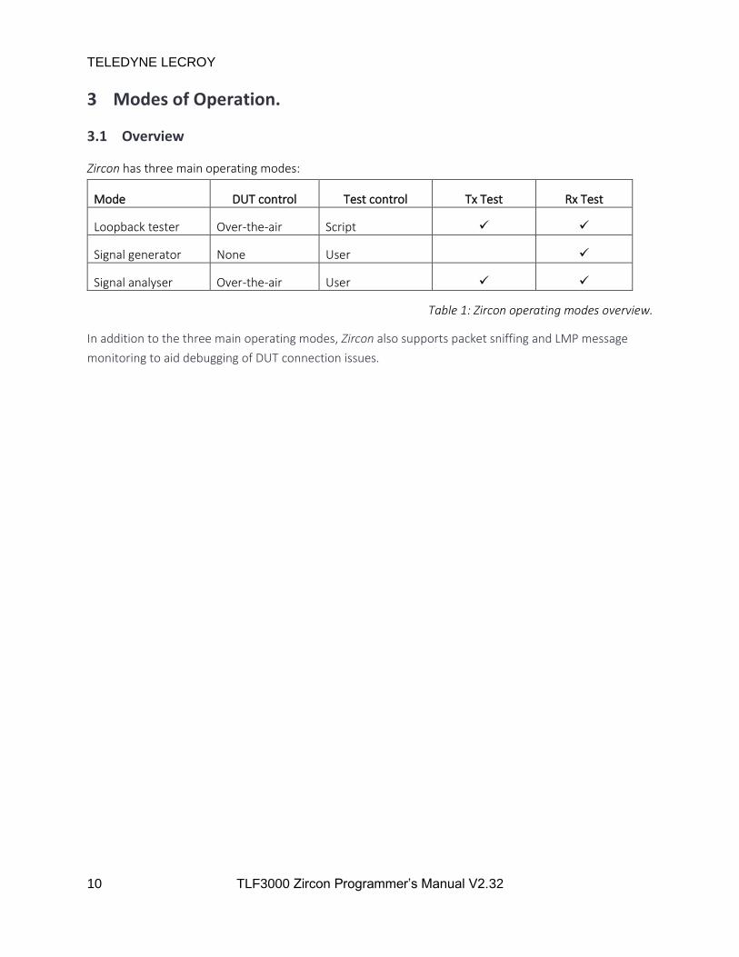
3 Modes of Operation.
3.1 Overview
Zircon has three main operating modes:
Mode DUT control Test control Tx Test Rx Test
Loopback tester Over-the-air Script
Signal generator None User
Signal analyser Over-the-air User
Table 1: Zircon operating modes overview.
In addition to the three main operating modes, Zircon also supports packet sniffing and LMP message
monitoring to aid debugging of DUT connection issues.
TELEDYNE LECROY
11 TLF3000 Zircon Programmer’s Manual V2.32
4 Phy Level Tester Mode
4.1 Overview
The loopback tester mode executes tests in accordance with the Bluetooth Radio Frequency Test
Specification. The tests to be performed are entered into a script which is then executed by Zircon. The
DUT is automatically controlled by Zircon over-the-air.
All tests are fully parameterised, permitting exploration of margin against the Bluetooth 5 specification
or datasheet figures.
4.1.1 Supported tests
Zircon supports the following phy level tests:
Test number Test description Phy Limitations
RF/TRM/CA/BV-01-C Output power BR
RF/TRM/CA/BV-02-C Power density BR See (a)
RF/TRM/CA/BV-03-C Power control BR
RF/TRM/CA/BV-04-C Tx output spectrum – frequency range BR
RF/TRM/CA/BV-05-C Tx output spectrum – 20dB bandwidth BR
RF/TRM/CA/BV-06-C Tx output spectrum – adjacent channel power BR
RF/TRM/CA/BV-7-C Modulation characteristics BR
RF/TRM/CA/BV-8-C Initial carrier frequency tolerance BR
RF/TRM/CA/BV-9-C Carrier frequency drift BR
RF/TRM/CA/BV-10-C EDR relative transmit power 2-EDR/3-EDR
RF/TRM/CA/BV-11-C EDR carrier frequency stability & modulation accuracy 2-EDR/3-EDR
RF/TRM/CA/BV-12-C EDR differential phase encoding 2-EDR/3-EDR
RF/TRM/CA/BV-13-C EDR in0band spurious emissions 2-EDR/3-EDR
RF/TRM/CA/BV-14-C Enhanced power control 2-EDR/3-EDR
RF/TRM/CA/BV-15-C EDR guard time 2-EDR/3-EDR
RF/TRM/CA/BV-16-C EDR synchronization sequence & trailer 2-EDR/3-EDR
RF/RCV/CA/BV-01-C Sensitivity – single slot packets 2-EDR/3-EDR
RF/RCV/CA/BV-02-C Sensitivity – multi slot packets BR
RF/RCV/CA/BV-03-C C/I performance BR
RF/RCV/CA/BV-04-C Blocking performance BR See (b)
RF/RCV/CA/BV-05-C Intermodulation performance BR See (c)
RF/RCV/CA/BV-06-C Maximum input level BR
RF/RCV/CA/BV-07-C EDR sensitivity 2 Mbps
RF/RCV/CA/BV-08-C EDR BER floor performance 2-EDR/3-EDR
RF/RCV/CA/BV-09-C EDR C/I performance 2-EDR/3-EDR
RF/RCV/CA/BV-10-C EDR maximum input level 2-EDR/3-EDR
TELEDYNE LECROY
12 TLF3000 Zircon Programmer’s Manual V2.32
Limitations:
a) The initial sweep for the power density is performed over 90MHz and not 240MHz as per
the specification. Unless the device under test has severe issues, this should return the
correct frequency for the second scan and hence the correct value for the power density.
b) Blocking tests are limited to the range 25 MHz to 6 GHz and to blocking levels of
approximately -30dBm or less. This is substantially less coverage than dictated by the
specification. It should be possible to perform blocking tests in the range 2GHz to 3GHz
without additional test equipment. However additional test equipment will be required to
evaluate the blocking performance outside this range. The unit contains a high-
performance F-BAR filter at its input and possesses an extremely high dynamic range. This
ensures that the DUT will always be blocked before the tester. The unit can also provide a
gating signal for the blocker to ensure it is off when the DUT is attempting to transmit.
The intermodulation test can be performed provided both the CW and continuous interferers lie within
the range 2395MHz to 2485MHz. This can always be arranged by choosing whether they are placed
above or below the wanted signal.
4.1.2 Scripting
RF Phy level tests are performed by downloading a test script to the Zircon application and then
executing the script. When multiple units are to be tested, the test script need only be downloaded
once.
The test script is an ASCII formatted file. Each line in the test script corresponds to one of the Bluetooth
test cases. If only the test name is specified, then the default parameters for that test are assumed; i.e.
the test it carried out in accordance with the Bluetooth 5 BR/EDR RF PHY Test Specification (RF.TS.p30).
However, each test also permits a number of quantities to be parameterized, such as:
1. RF channels to be tested.
2. Packet lengths to be used.
3. Number of packets to be used in the test.
4. Wanted signal levels.
5. Interferer signal levels.
6. Interferer signal frequencies.
This parameterisation of the tests permits DUTs to be tested outside the Bluetooth specification and
hence the margin against the Bluetooth specification to be determined. It also allows devices to be
tested against a manufacturers’ datasheet rather than the Bluetooth specification.

TELEDYNE LECROY
13 TLF3000 Zircon Programmer’s Manual V2.32
4.1.3 Parameter searches
Each parameter which can be specified can be entered either as a single value or a range of values. For
example, the channels to be tested could be specified as:
1. 39 – a single channel
1. 1,12,39 – a list of channels
2. 1,12,39,3:10 – a list of channels plus a range of channels
By enabling complex ranges of parameters to be specified, automated testing of specific scenarios can
be achieved.
Furthermore, by specifying a range of parameters for quantities such as wanted signal level, the
sensitivity of the DUT can automatically be searched for.
4.1.4 External Connectivity
In phy test mode the following connectivity is required:
1. RF connection between the DUT and the TLF3000. This would normally be a calibrated cabled
connection between the DUT and the TLF3000 Tx/Rx port. However, it is also possible to
perform radiated testing. In radiated test mode, the unit will transmit on the Tx/Rx port and can
receive on either the Tx/Rx port or the more sensitive Monitor In port.
2. Control connection to the TLF3000. This would normally be a USB or Ethernet connection to a
host machine. However, the starting and stopping of a test script can also be controlled via
digital input lines and the results displayed using digital output lines. This facility allows TLF3000
to be incorporated into a range of test facilities.
TELEDYNE LECROY
14 TLF3000 Zircon Programmer’s Manual V2.32
4.2 Signal Generator Mode
4.2.1 Overview
The signal generator is able to produce any combination of the following signals:
1. Packetized BR/EDR test signal
2. Continuously modulated or packetised BR interferer signal
3. Tow independent in-band CW signals
4. In-band AWGN
5. Out-of-band CW signal.
4.2.2 Wanted signal
A packetised wanted signal to be received by the DUT can be generated. This is parameterised by:
1. Frequency: 2395 to 2485MHz in 1MHz steps
2. Amplitude: -120 dBm to 0 dBm for basic rate pakets and -120 dBm to -3.1 dBm for EDR packets
with a resolution of 0.1 dBm.
3. Packet type: all Bluetooth packets types except DV
4. Bluetooth address
5. Whitening
6. Packet payload:
a. PRBS9 sequence
b. PRBS15 sequence
c. PRBS11 sequence
d. PRBS20 sequence
e. PRBS23 sequence
f. PRBS29 sequence
g. PRBS31 sequence
h. 11110000 in transmission order
i. 10101010 in transmission order
j. 11111111 in transmission order
k. 00000000 in transmission order
l. 00001111 in transmission order
m. 01010101 in transmission order
n. User defined
7. Payload length
8. Packet interval: packet duration to 5s
9. Number of packets to be transmitted: 1 to 65535, or continuous
10. Dirty or standard transmitter
11. Dirty transmitter parameters:
a. Carrier frequency offset: -250 kHz to +250 kHz.
TELEDYNE LECROY
15 TLF3000 Zircon Programmer’s Manual V2.32
b. Modulation index: 0.23 to 0.4
c. Drift magnitude: 0 to 78 kHz.
d. Drift rate: 0 to 20000 Hz
e. Symbol timing error: -100 ppm to +100 ppm
12. Ramp time: 1 to 10µs
The drift magnitude and drift rate follow the definitions in the Bluetooth 5 RF PHY Test Specification.
The drift follows a sinusoidal waveform whose period is given by the drift rate and whose amplitude is
determined by the drift magnitude. The drift is always zero at the start of basic rate packets or at the
start of the EDR portion of the paclet for EDR packets. The sign of the drift amplitude is inverted on
alternate packets.
The dirty transmitter is defined by an arbitrary length list, each element in the list specifying:
1. Carrier frequency offset
2. Modulation index
3. Drift magnitude
4. Drift rate
5. Symbol timing error
The first element in the list is used to define the first 20ms for basic rate packets or 20 packets for EDR,
with alternate packets having the sign of the drift reversed. The next 20ms or 20 packets to be
transmitted are defined by the second element in the list, and so on. If more packets are to be
transmitted than there are definitions in the list, then the contents of the list are repeated until all
packets have been transmitted.
If any of the wanted signal parameters are changed whilst the wanted signal is being transmitted, then
the current transmission is aborted and the wanted signal plus any interfering signals restarted.
4.2.3 Interfering signal
An interfering signal with PRBS payload to be used in C/I and intermodulation tests. This signal is
parameterised by:
1. Frequency: 2395 MHz to 2485 MHz in steps of 1 MHz
2. Amplitude: -120 dBm to 0 dBm with a resolution of 0.1 dBm
3. Modulation: Basic rate
3. Contents of payload: PRBS15
4. Whether the interferer is a continuous signal or packetised
5. The payload length, if the interferer signal is packetised
6. The packet interval, if the interferer signal is packetised

TELEDYNE LECROY
16 TLF3000 Zircon Programmer’s Manual V2.32
Although this is can be a continuous signal, on commencement of a transmission a valid preamble and
access code are sent prior to the PRBS payload. Hence there are a few µs at the start of each test period
before the PRBS sequence commences. The wanted signal is always delayed until this period has passed.
If any of the interfering signal parameters are changed whilst the interferer signal is active, then the
current transmission is aborted, and all wanted and interfering signals restarted.
4.2.4 Primary and Seconadry In-band CW signals
Two in-band CW signals which can be used in intermodulation testing. These signals could also be used
for custom receiver selectivity testing. The signals are parameterised by:
1. Frequency: 2395 MHz to 2485 MHz in steps of 1 kHz
2. Amplitude: -120 dBm to 0 dBm with a resolution of 0.1 dBm
If any of the in-band CW signal parameters are changed whilst the in-band CW signal is active, then the
current transmission is aborted, and all wanted and interfering signals restarted.
4.2.5 AWGN signal
An AWGN signal covering 2395 to 2485MHz can be generated. The amplitude of this signal can be set
between -162dBm/MHz and -42dBm/MHz. This signal permits the SNR of the wanted signal to be
accurately controlled, which can be useful for testing the implementation of digital demodulators.
4.2.6 Out-of-band CW signal
An out-of-band CW signal to be used in receiver blocking tests. This signal can typically be generated at a
level up to -25 dBm. The frequency of the signal can be in the range 25 MHz to 6 GHz with a resolution
of 1 MHz.
The CW generator within the TLF3000 unit possesses significant harmonic content. When a harmonic
lies within the 2.4 GHz ISM band, it is possible for the DUT to be blocked by the harmonic and not the
fundamental. This issue is not unique to the TLF3000; harmonic content is also an issue when using
external signal generators to provide the blocking signal. For example, an R&S SMW200A specifies
harmonic content as < -30 dBc. If this unit were to generate a blocking signal at 1201 MHz with a level of
-30 dBm, then it may generate a second harmonic at 2402 MHz with a level of -60 dBm. Given that the
DUT is being tested at a sensitivity level of at least -67 dBm, it is clear that the DUT will be blocked by
the harmonic and not the fundamental.
To help alleviate this problem, the TLF3000 contains a 2.4 GHz notch filter in the out-of-band CW signal
path. This notch filter is switched in whenever the blocking signal is below 1500 MHz. Hence the
harmonic content of the blocker within the 2.4 GHz ISM band is greatly attenuated. However, when
testing sensitive receivers, it should always be borne in mind that any blocking failures could be due to
harmonics of the blocking signal and not the fundamental.
TELEDYNE LECROY
17 TLF3000 Zircon Programmer’s Manual V2.32
The out-of-band CW signal can be modified at any time without affecting the wanted or in-band
interfering signals.
4.3 Signal Analyser Mode
4.3.1 Overview
In signal analyser mode, the Zircon application can analyse incoming signals against the transmitter tests
contained within the Bluetooth Radio Frequency Test Specification. The signals may originate from a DUT
controlled by the signal analyser or be unwhitened signals from a DUT controlled by other means, ie the
signal analyser can operate in both signalling and non-signalling modes. The application can analyse both
conducted and off-air signals.
If the DUT is controlled over-the-air, then receiver tests can also be performed. The signal analyser mode
permits sensitivity, maximum input signal, C/I and intermodulation tests to be carried out.
When performing transmitter tests, all 79 Bluetooth channels are monitored simultaneously, hence there
is no requirement to program the signal analyser to look on a specified channel or to look for a specific
packet type. The signal analyser accumulates results separately for each channel, number of packet slots
and modulation method. This permits the results to be filtered and displayed in a number of different
ways.
4.3.2 Capture port
The Zircon application can receive packets on one of two ports:
1. Tx/Rx port. This port has a noise figure of +46 dB and can handle input signals as high as +27
dBm. Use this port for conducted measurements.
2. Monitor In port. This port has a noise figure of +6 dB and a maximum usable input signal level of
-10 dBm. Use this port for off-air measurements.

TELEDYNE LECROY
18 TLF3000 Zircon Programmer’s Manual V2.32
5 Python Interface
5.1 Overview
Support is provided for driving the TLF3000 directly from Python on a Windows or Linux platform. This
support is available for Python 3.8 or later. Both 32 bit and 64 bit versions are available.
5.1.1 Prerequistes
To import the Zircon module, include the location of the appropriate Zircon library on the current path.
Then import the following:
sys.path.append('D:/Users/timbo/build-pyFrontline_MSVC2017_32bit_2v7-Release')
from Frontline import MorephDevice, MorephSearch, MorephInterface, ZirconInterface,
vector_uchar, vector_float, vector_int16, vector_char
5.1.2 Connecting to the TLF3000
To connect to the TLF3000 it is first necessary to create a search engine by calling MorephSearch.get().
Having obtained a search engine, the following operations should be performed:
1. Attach a callback to the search engine by invoking the callback() method. The callback will
process the TLF3000s that are discovered by the search engine.
2. Start the search engine by invoking the start() method.
Whenever a TLF3000 is discovered, the callback will be entered with a handle to the device and a flag to
indicate whether it was discovered on USB or Ethernet. In the example code below, the callback
appends the device to a list if it is a USB device or an Ethernet device.
In the example program, the main thread monitors the contents of the list. Whenever a new entry is
placed on the list, the main thread obtains an interface to the device by invoking the MorephInterface()
method. Having obtained an interface to the device, the friendly name, serial number and current IP
address are interrogated. If these satisfy certain search criteria, then the required device has been found
and opened, otherwise the entry is discarded from the list.
Once the required device has been found, the search engine is stopped by invoking the stop() method.
from __future__ import print_function
import sys, struct
from collections import namedtuple
from time import sleep
sys.path.append('D:/Users/timbo/build-pyFrontline_MSVC2017_32bit_2v7-Release')
from Frontline import MorephDevice, MorephSearch, MorephInterface, ZirconInterface,
vector_uchar, vector_float, vector_int16, vector_char
TLF3000Name = "TLF3000"
TLF3000SerialNumber = 172
TELEDYNE LECROY
19 TLF3000 Zircon Programmer’s Manual V2.32
"""
Connect to first device found which matches either TLF3000Name or TLF3000SerialNumber
"""
def connect():
tlf3000 = []
ms = MorephSearch.get()
def callback(m):
if ( (m.type == MorephDevice.USB) | (m.type == MorephDevice.Eth) ):
tlf3000.append(m)
ms.set_callback(callback)
ms.start()
found = False
while True:
while len(tlf3000):
try:
transport = tlf3000[0].getTransport();
mi = MorephInterface(transport)
name = mi.getFriendlyName()
sn = mi.getSerialNumber()
net = mi.getNetwork()
print( "Found" , name , sn , hex(net.cur_ip) )
if( (name == TLF3000Name) | (sn == TLF3000SerialNumber) ):
found = True
break
del tlf3000[0]
break
except:
del tlf3000[0]
if found:
break
sleep(0.1)
print( "Stop" )
ms.stop()
print("Opening TLF3000" )
return transport
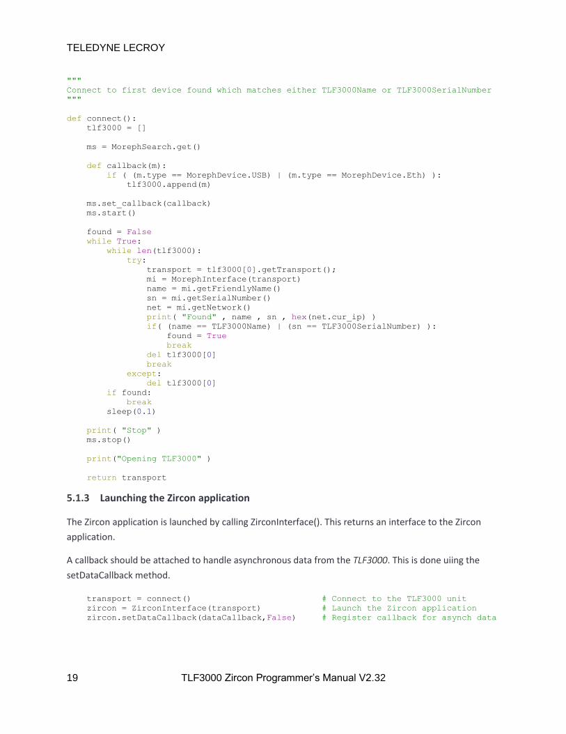
5.1.3 Launching the Zircon application
The Zircon application is launched by calling ZirconInterface(). This returns an interface to the Zircon
application.
A callback should be attached to handle asynchronous data from the TLF3000. This is done uiing the
setDataCallback method.
transport = connect() # Connect to the TLF3000 unit
zircon = ZirconInterface(transport) # Launch the Zircon application
zircon.setDataCallback(dataCallback,False) # Register callback for asynch data

TELEDYNE LECROY
20 TLF3000 Zircon Programmer’s Manual V2.32
5.1.4 Handling asynchronouos data
Whenever an asynchronous message is received from the TLF3000, the asynchronous data callback will
be entered. In the example below, the data is unpacked to determine its length and type. Having
determined the message type, it is dispatched to an appropriate routine.
"""
Main callback for handling messages on the asynch data channel
These are then dispatched to the next level callback handler
"""
pktType =
0: startScript,
1: txTest,
2: rxTest,
3: endScript,
4: startLine,
5: endLine,
6: extraBR,
7: extraEDR,
64: siganaTerm,
65: inquiryComplete,
66: inquiryResponse,
67: pageComplete,
68: extInqRep,
69: dutName,
95: lmpLost,
96: lmpTo,
97: lmpFrom,
98: lmpJoin,
99: lmpLeave,
100: wireshark,
101: endSniff,
102: siganaChange,
110: guiOnly,
193: envData,
194: pwrData,
195: running
pkthdr = namedtuple('hdr', 'n nMsb typ')
pkthdrbin = '<HBB'
def dataCallback(d):
s = pkthdr(*struct.unpack(pkthdrbin, d[0:4]))
pktType.get( s.typ )(d)
TELEDYNE LECROY
21 TLF3000 Zircon Programmer’s Manual V2.32
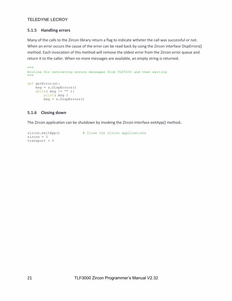
5.1.5 Handling errors
Many of the calls to the Zircon library return a flag to indicate wtheter the call was successful or not.
When an error occurs the cause of the error can be read back by using the Zircon interface DispErrors()
method. Each invocation of this method will remove the oldest error from the Zircon error queue and
return it to the caller. When no more messages are available, an empty string is returned.
"""
Routine for retrieving errors messages from TLF3000 and then exiting
"""
def getError(s):
msg = s.DispErrors()
while( msg != "" ):
print( msg )
msg = s.DispErrors()
5.1.6 Closing down
The Zircon application can be shutdown by invoking the Zircon interface exitApp() method..
zircon.exitApp() # Close the zircon applications
zircon = 0
transport = 0
TELEDYNE LECROY
22 TLF3000 Zircon Programmer’s Manual V2.32
5.2 Examples
5.2.1 Running a phy test script
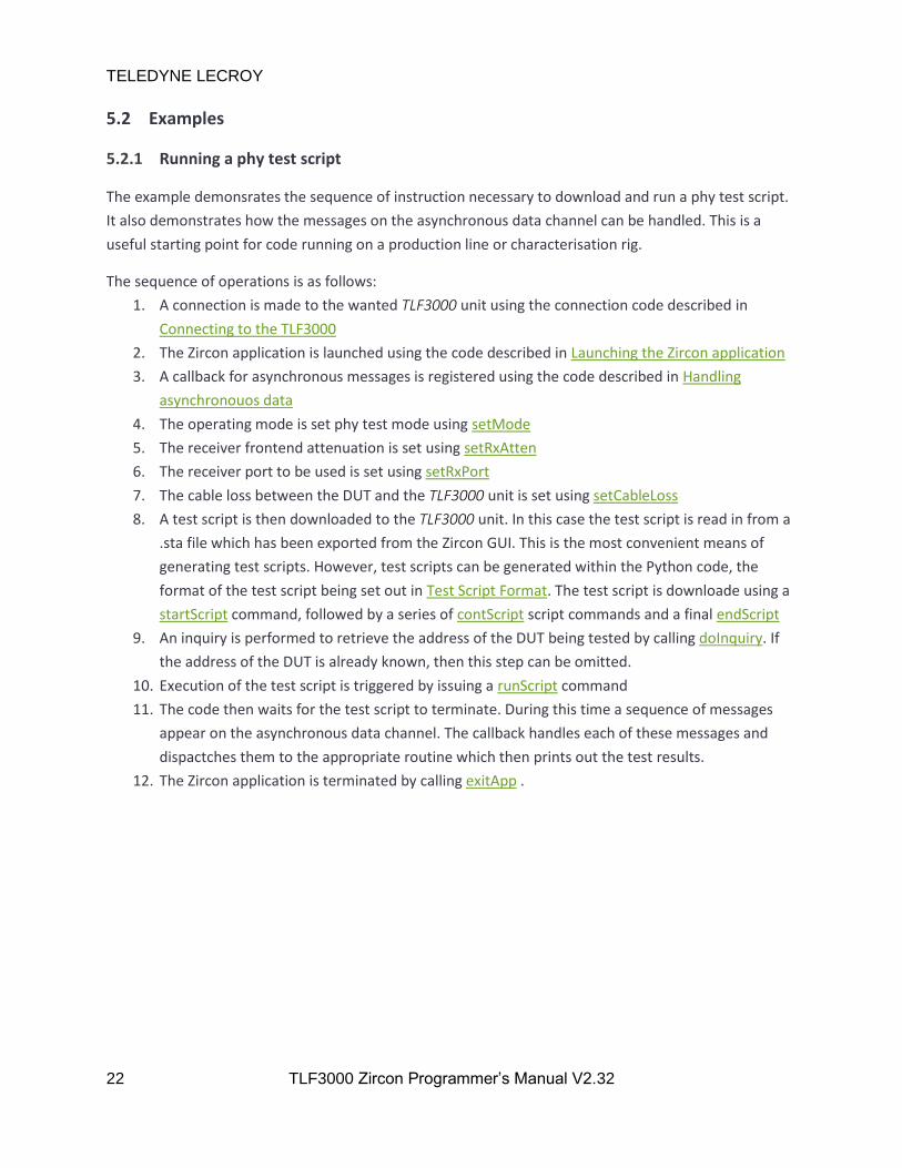
The example demonsrates the sequence of instruction necessary to download and run a phy test script.
It also demonstrates how the messages on the asynchronous data channel can be handled. This is a
useful starting point for code running on a production line or characterisation rig.
The sequence of operations is as follows:
1. A connection is made to the wanted TLF3000 unit using the connection code described in
Connecting to the TLF3000
2. The Zircon application is launched using the code described in Launching the Zircon application
3. A callback for asynchronous messages is registered using the code described in Handling
asynchronouos data
4. The operating mode is set phy test mode using setMode
5. The receiver frontend attenuation is set using setRxAtten
6. The receiver port to be used is set using setRxPort
7. The cable loss between the DUT and the TLF3000 unit is set using setCableLoss
8. A test script is then downloaded to the TLF3000 unit. In this case the test script is read in from a
.sta file which has been exported from the Zircon GUI. This is the most convenient means of
generating test scripts. However, test scripts can be generated within the Python code, the
format of the test script being set out in Test Script Format. The test script is downloade using a
startScript command, followed by a series of contScript script commands and a final endScript
9. An inquiry is performed to retrieve the address of the DUT being tested by calling doInquiry. If
the address of the DUT is already known, then this step can be omitted.
10. Execution of the test script is triggered by issuing a runScript command
11. The code then waits for the test script to terminate. During this time a sequence of messages
appear on the asynchronous data channel. The callback handles each of these messages and
dispactches them to the appropriate routine which then prints out the test results.
12. The Zircon application is terminated by calling exitApp .

"""
Main script for phy test example
"""
if __name__ == '__main__':
global done
global addr
global lastTestNum # Variables used to help format printing of results
global oldChan
global oldInfo
global oldPktTyp
global oldSubTest
global oldIchan
global oldMHz
global oldN
lastTestNum = 99
oldChan = 99
oldInfo = 0
oldPktTyp = -1
oldSubTest = 99
oldIchan = 99
oldMHz = 0
oldN = 99
transport = connect() # Connect to the TLF3000 unit
zircon = ZirconInterface(transport) # Launch the Zircon application
zircon.setDataCallback(dataCallback,False) # Register callback for asynch data channel
if( not zircon.setMode( 0 ) ): # Enter phy tester mode
getError(zircon)
if( not zircon.setRxAtten( 0 ) ): # Set rx frontend attenuation in units of 0.5dB
getError(zircon)
if( not zircon.setRxPort( 1 ) ): # Set the rx port to be tx/rx
getError(zircon)
if( not zircon.setCableLoss( 10.0 ) ): # Set cable loss in units of dB
getError(zircon)
# Start download of test script
# Overwrite file with existing name

TELEDYNE LECROY
24 TLF3000 Zircon Programmer’s Manual V2.32
# Do not place in FLASH (currently not supported)
# Test script file name
if( not zircon.startScript( True , False , "TestScript" ) ):
getError(zircon)
with open( TestScriptFile , "r" ) as f:
for line in f:
if( not zircon.contScript(line) ): # Add lines to test script file
getError(zircon)
quit()
if( not zircon.endScript() ): # Signal that the test script is now complete
getError(zircon)
f.close()
# Do an iqnuiry to get address of device to test
# (this may be unnecessary if address is already known)
# Start/stop
# Duration in ms
# Inquiry power in dBm
# RSSI threshold in dBm
# Number of expected response (will terminate once this
# number of response have been seen)
done = False
if( not zircon.doInquiry( True , 5000 , -40 , -40 , 1 ) ):
getError(zircon)
while( not done ): # Loop until we have inquiry response or inquiry terminates
msg = zircon.DispErrors()
if( msg != "" ):
print( msg )
else:
sleep(0.1)
# Run the test script
# Address of device
# Paging timeout in ms
# Power used to page device in dBm
# Power used for LMP packets in dBm
# Power used for poll packets in transmit test mode in dBm
# RSSI threshold below which received packets will be
# ignored in dBm
# Supervision timeout in ms
# Number of times script should be run
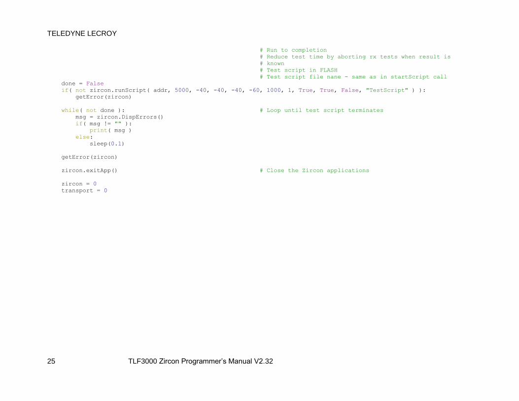
TELEDYNE LECROY
25 TLF3000 Zircon Programmer’s Manual V2.32
# Run to completion
# Reduce test time by aborting rx tests when result is
# known
# Test script in FLASH
# Test script file nane - same as in startScript call
done = False
if( not zircon.runScript( addr, 5000, -40, -40, -40, -60, 1000, 1, True, True, False, "TestScript" ) ):
getError(zircon)
while( not done ): # Loop until test script terminates
msg = zircon.DispErrors()
if( msg != "" ):
print( msg )
else:
sleep(0.1)
getError(zircon)
zircon.exitApp() # Close the Zircon applications
zircon = 0
transport = 0

5.2.1.1 Inquiry and connection callbacks
When an inquiry is initiated, all responses to the inquiry are directed to asynchronous callbacks. When a
device responds to an inquiry, then the address of the device and the RSSI of the response can be
determined:
inqresp = namedtuple('inqresp', 'hdr n rssi dummy addr')
inqrespbin = '<LHbBQ'
def inquiryResponse( d ):
global addr
s = inqresp(*struct.unpack(inqrespbin, d[0:16]))
addr = s.addr
addr = ((addr & 0xFFFFFFFF) << 32) | (addr >> 32)
print( "Inquiry response %08X" % s.addr , " with RSSI %d" % s.rssi )
An asynchronous callback is also called once the inquiry has terminated:
def inquiryComplete( d ):
global done
print( "Inquiry complete" )
done = True
Whenever a connection to a device is closed or lost, another asynchronous callback is invoked:
def pageComplete( d ):
print( "Connection terminated" )
TELEDYNE LECROY
27 TLF3000 Zircon Programmer’s Manual V2.32
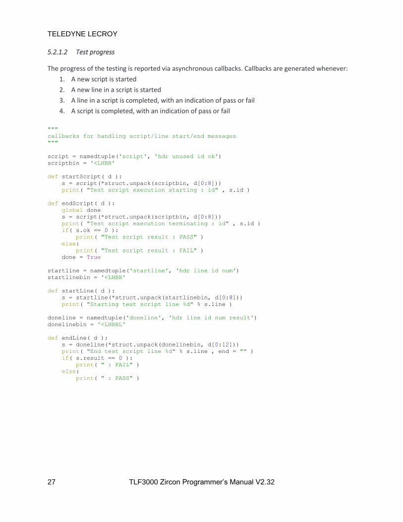
5.2.1.2 Test progress
The progress of the testing is reported via asynchronous callbacks. Callbacks are generated whenever:
1. A new script is started
2. A new line in a script is started
3. A line in a script is completed, with an indication of pass or fail
4. A script is completed, with an indication of pass or fail
"""
callbacks for handling script/line start/end messages
"""
script = namedtuple('script', 'hdr unused id ok')
scriptbin = '<LHBB'
def startScript( d ):
s = script(*struct.unpack(scriptbin, d[0:8]))
print( "Test script execution starting : id" , s.id )
def endScript( d ):
global done
s = script(*struct.unpack(scriptbin, d[0:8]))
print( "Test script execution terminating : id" , s.id )
if( s.ok == 0 ):
print( "Test script result : PASS" )
else:
print( "Test script result : FAIL" )
done = True
startline = namedtuple('startline', 'hdr line id num')
startlinebin = '<LHBB'
def startLine( d ):
s = startline(*struct.unpack(startlinebin, d[0:8]))
print( "Starting test script line %d" % s.line )
doneline = namedtuple('doneline', 'hdr line id num result')
donelinebin = '<LHBBL'
def endLine( d ):
s = doneline(*struct.unpack(donelinebin, d[0:12]))
print( "End test script line %d" % s.line , end = "" )
if( s.result == 0 ):
print( " : FAIL" )
else:
print( " : PASS" )

TELEDYNE LECROY
28 TLF3000 Zircon Programmer’s Manual V2.32
5.2.1.3 Tables for decoding results
The example code utilises the following tables to decode the test results returned.
pktNames = [ "ID", "NULL", "POLL", "FHS", "DM1", "DH1", "DM3", "DH3", "DM5", "DH5",
"AUX1", "2-DH1", "2-DH3", "2-DH5", "3-DH1", "3-DH3", "3-DH5", "HV1",
"HV2", "HV3", "DV", "EV3", "EV4", "EV5", "2-EV3", "2-EV5", "3-EV3",
"3-EV5" ]
pktPayloads = [ "PRBS9", "11110000", "10101010", "11111111", "00000000", "????????",
"????????", "????????" ]
rxTitles = [ "" , "Sensitivity - single slot" , "Sensitivity - multi slot" ,
"C/I Performance" , "Blocking" , "Intermodulation" ,
"Maximum input level" , "EDR sensitivity" ,
"EDR BER floor performance" , "EDR C/I Performance" ,
"EDR maximum input level" ]
5.2.1.4 Common routines
The example code used some common utility routines for printing out the results. This routine is used to
print information common to most tests excluding those involving receiver interference:
def commonOutput(TestNum, chan, pktTyp, info):
global lastTestNum
global oldChan
global oldInfo
global oldPktTyp
global oldSubTest
global oldIchan
global oldMHz
global oldN
TestNum = (TestNum >> 4) & 0xFF
print(" (RF_TRM_CA_BV_%02d_C)" % TestNum , end = "" )
print(" : RF Channel %d" % chan , end = "" )
print(" : %s" % pktNames[pktTyp] , end = "" )
print(" : %s" % pktPayloads[(info >> 4) & 7] , end = "" )
if( info & 1 ):
print(" : Hopping" , end = "" )
else:
print( " : Non-hopping" , end = "" )
if( info & 2 ):
print(" : Loopback" , end = "" )
else:
print(" : Tx mode" , end = "" )
if( info & 4 ):
print(" : Whitened" )
else:
print(" : Not whitened")
if( lastTestNum != TestNum ):
oldChan = 99
oldInfo = 0
oldPktTyp = -1
oldSubTest = 99
oldIchan = 99
oldMHz = 0
oldN = 99
lastTestNum = TestNum

TELEDYNE LECROY
29 TLF3000 Zircon Programmer’s Manual V2.32
Tests involving receiver interference use this common routine:
def commonOutputInterferer(TestNum, chan, iChan, pktTyp, info, units):
global lastTestNum
global oldChan
global oldInfo
global oldPktTyp
global oldSubTest
global oldIchan
global oldMHz
global oldN
TestNum = (TestNum >> 4) & 0xFF
print(" (RF_TRM_CA_BV_%02d_C)" % TestNum , end = "" )
print(" : RF Channel %d" % chan , end = "" )
if( units == 0 ):
print(" : Interferer Channel %d" % iChan , end = "" )
elif( units == 1 ):
print(" : Interferer frequency %d MHz" % iChan , end = "" )
else:
print(" : Interferer spacing %d" % iChan , end = "" )
print(" : %s" % pktNames[pktTyp] , end = "" )
print(" : %s" % pktPayloads[(info >> 4) & 7] , end = "" )
if( info & 1 ):
print(" : Hopping" , end = "" )
else:
print( " : Non-hopping" , end = "" )
if( info & 2 ):
print(" : Loopback" , end = "" )
else:
print(" : Tx mode" , end = "" )
if( info & 4 ):
print(" : Whitened" )
else:
print(" : Not whitened")
if( lastTestNum != TestNum ):
oldChan = 99
oldInfo = 0
oldPktTyp = -1
oldSubTest = 99
oldIchan = 99
oldMHz = 0
oldN = 99
lastTestNum = TestNum
And the pass/fail result is output by this routine:
def commonPass(result):
if( result ):
print( " ( FAIL )" )
else:
print( " ( PASS )" )

TELEDYNE LECROY
30 TLF3000 Zircon Programmer’s Manual V2.32
5.2.1.5 Transtmitter test results
Transmitter test results are directed through a single routine called by the main asynchronous callback
handler. The nature of the transmitter test is determined and an appropriate routine for handling the
asynchronous data is called.
"""
Dictionary to map test numbers to callbacks
"""
txType =
1: outputPower,
2: powerDensity,
3: powerControl,
4: frequencyRange,
5: bandwidth20dB,
6: adjacentChannelPower,
7: modulationCharacteristics,
8: initialCarrierFrequency,
9: carrierFrequencyDrift,
10: edrRelativeTransmitPower,
11: edrCarrierFrequencyStabilityAndModulationAccuracy,
12: edrDifferentialPhaseEncoding,
13: edrInBandSpuriousEmissions,
14: enhancedPowerControl,
15: edrGuardTime,
16: edrSynchronisationSequenceAndTrailer
"""
Callbacks for handling transmit messages
These are passed to the appropraite message handler
"""
txhdr = namedtuple('txhdr', 'hdr line TestNum')
txhdrbin = '<LHH'
def txTest(d):
s = txhdr(*struct.unpack(txhdrbin, d[0:8]))
SubTest = s.TestNum >> 12;
TestNum = (s.TestNum >> 4) & 0xFF;
txType.get( TestNum )(d,SubTest)
TELEDYNE LECROY
31 TLF3000 Zircon Programmer’s Manual V2.32
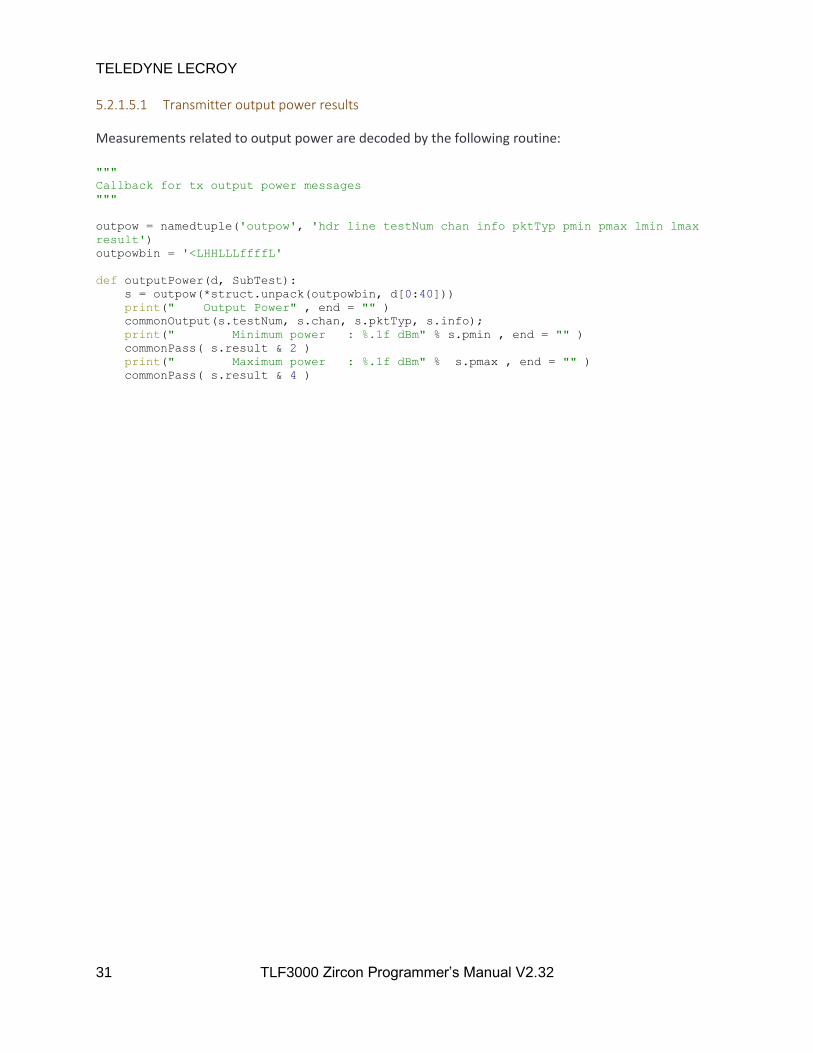
5.2.1.5.1 Transmitter output power results
Measurements related to output power are decoded by the following routine:
"""
Callback for tx output power messages
"""
outpow = namedtuple('outpow', 'hdr line testNum chan info pktTyp pmin pmax lmin lmax
result')
outpowbin = '<LHHLLLffffL'
def outputPower(d, SubTest):
s = outpow(*struct.unpack(outpowbin, d[0:40]))
print(" Output Power" , end = "" )
commonOutput(s.testNum, s.chan, s.pktTyp, s.info);
print(" Minimum power : %.1f dBm" % s.pmin , end = "" )
commonPass( s.result & 2 )
print(" Maximum power : %.1f dBm" % s.pmax , end = "" )
commonPass( s.result & 4 )

TELEDYNE LECROY
32 TLF3000 Zircon Programmer’s Manual V2.32
5.2.1.5.2 Transmitter power density results
Measurements related to power density are decoded by the following routine. The object “spectrum”
holds the results of the power density measurements on 901 channels in units of dBm. The first channel
is 2395MHz and the last channel is 2485MHz in steps of 100kHz.
"""
Callback for tx power density
"""
powdens = namedtuple('powdens', 'hdr line testNum chan info pktTyp pmin pmax lmin lmax
result')
powdensbin = '<LHHLLLffffL'
powdenshdr = namedtuple('powdenshdr', 'hdr line testNum chan info pktTyp')
powdenshdrbin = '<LHHLLL'
def powerDensity(d, SubTest):
if( SubTest == 0 ):
s = powdens(*struct.unpack(powdensbin, d[0:40]))
print(" Maximum power : %.1f dBm/100kHz" % s.pmax , end = "" )
commonPass( s.result & 1 )
elif (SubTest == 1):
s = powdens(*struct.unpack(powdensbin, d[0:40]))
print(" Power density" , end = "" )
commonOutput(s.testNum, s.chan, s.pktTyp, s.info)
print(" Peak frequency : %.1f MHz" % s.pmax)
elif (SubTest == 2):
s = powdenshdr(*struct.unpack(powdenshdrbin, d[0:20]))
# Spectrum is 901 points @ 100kHz resolution
# First point is 2395MHz and last point is 2485MHz
spectrum = struct.unpack( '901f' , d[20:3624] )
print( "Power density spectrum" )
else:
print("Unknown sub test %d" % SubTest)

TELEDYNE LECROY
33 TLF3000 Zircon Programmer’s Manual V2.32
5.2.1.5.3 Transmitter power control results
Measurements related to power control are decoded by the following routine:
"""
Callback for tx power control
"""
powctrl = namedtuple('powctrl', 'hdr line testNum chan info pktTyp pmin pmax lmin lmax
result')
powctrlbin = '<LHHLLLffffL'
def powerControl(d, SubTest):
global oldChan
global oldInfo
global oldPktTyp
s = powctrl(*struct.unpack(powctrlbin, d[0:40]))
if ((s.chan != oldChan) or (oldInfo != s.info) or (oldPktTyp != s.pktTyp)):
print(" Power control" , end = "" )
commonOutput(s.testNum, s.chan, s.pktTyp, s.info)
oldChan = s.chan
oldInfo = s.info
oldPktTyp = s.pktTyp
if (SubTest == 0):
print(" Power step down : %.1f dBm" % s.pmin , end = "" )
commonPass( s.result & 1 )
elif (SubTest == 1):
print(" Minimum power : %.1f dBm" % s.pmin , end = "" )
commonPass( s.result & 1 )
elif (SubTest == 8):
print(" Power step up : %.1f dBm" % s.pmin , end = "" )
commonPass( s.result & 1 )
else:
print("Unknown sub test %d" % SubTest)

TELEDYNE LECROY
34 TLF3000 Zircon Programmer’s Manual V2.32
5.2.1.5.4 Transmitter frequency range results
Measurements related to frequency range are decoded by the following routine. The spectrum arrays
have a resolution of 100kHz and span 10MHz, starting at either 2395MHz or 2475MHz. They contain the
measured power in units of dBm.
"""
Callback for tx frequency range
"""
frqrange = namedtuple('frqrange', 'hdr line testNum chan info pktTyp X L result')
frqrangebin = '<LHHLLLffL'
frqrangehdr = namedtuple('frqrangehdr', 'hdr line testNum chan info pktTyp')
frqrangehdrbin = '<LHHLLL'
def frequencyRange(d, SubTest):
if (SubTest == 0) :
s = frqrange(*struct.unpack(frqrangebin, d[0:32]))
print(" Minimum range : %.1f MHz" % s.X , end = "" )
commonPass( s.result & 1 )
elif (SubTest == 1):
s = frqrange(*struct.unpack(frqrangebin, d[0:32]))
print(" Frequency range" , end = "" )
commonOutput(s.testNum, s.chan, s.pktTyp, s.info)
print(" Maximum range : %.1f MHz" % s.X , end = "" )
commonPass( s.result & 1 )
elif (SubTest == 2):
s = frqrangehdr(*struct.unpack(frqrangehdrbin, d[0:20]))
# Spectrum is 101 points @ 100kHz resolution
# First point is 2395MHz and last point is 2405MHz
spectrum = struct.unpack( '101f' , d[20:424] )
print("Fl Spectrum")
elif (SubTest == 3):
s = frqrangehdr(*struct.unpack(frqrangehdrbin, d[0:20]))
# Spectrum is 101 points @ 100kHz resolution
# First point is 2475MHz and last point is 2485MHz
spectrum = struct.unpack( '101f' , d[20:424] )
print("Fh Spectrum")
else:
print("Unknown sub test %d" % SubTest)

TELEDYNE LECROY
35 TLF3000 Zircon Programmer’s Manual V2.32
5.2.1.5.5 Transmitter 20dB bandwidth results
Measurements related to the transmitter 20dB bandwidth are decoded by the following routine. The
spectrum array contains 600 points with a resolution of 5kHz spanning ±1.5MHz from the nominal
carrier frequency. The spectrum units are dB relative to the maximum value measured.
"""
Callback for tx 20dB bandwidth
"""
bw20dB = namedtuple('bw20dB', 'hdr line testNum chan info pktTyp f20 fl fh lmax
result')
bw20dBbin = '<LHHLLLffffL'
def bandwidth20dB(d, SubTest):
s = bw20dB(*struct.unpack(bw20dBbin, d[0:40]))
print(" 20dB bandwidth" , end = "" )
commonOutput(s.testNum, s.chan, s.pktTyp, s.info)
print(" 20dB bandwidth : %.0f kHz" % s.f20 , end = "" )
commonPass( s.result & 1 )
# spectrum is 600 points @ 5kHz per point spanning +/- 1.5MHz from the carrier
# frequency
spectrum = struct.unpack( '600f' , d[40:2440] )

TELEDYNE LECROY
36 TLF3000 Zircon Programmer’s Manual V2.32
5.2.1.5.6 Transmitter adjacent channel power results
Measurements related to the transmitter adjacent channel power are decoded by the following routine.
Two spectra are returned. The first contains the ACP measurements every 1MHz from 2395MHz to
2485MHz inclusive. The second contains the 100kHz RBW measurements which were used to generate
the 1MHz resolution results. These measurements are from 2394.550MHz to 2485.450MHz in 100kHz
steps.
"""
Callback for tx adjacent channel power
"""
acp = namedtuple('acp', 'hdr line testNum chan info pktTyp pmin pmax lmin lmax
result')
acpbin = '<LHHLLLffffL'
def adjacentChannelPower(d, SubTest):
global oldSubTest
if( SubTest == 1 ):
s = acp(*struct.unpack(acpbin, d[0:40]))
print(" | M - N | = 2 : %.1f dBm" % s.pmax , end = "" )
commonPass( s.result & 1 )
elif (SubTest == 2):
s = acp(*struct.unpack(acpbin, d[0:40]))
print(" | M - N | >= 3 : %.1f dBm" % s.pmax , end = "" )
commonPass( s.result & 1 )
elif (SubTest == 3):
s = acp(*struct.unpack(acpbin, d[0:40]))
if (oldSubTest != 4):
print(" Adjacent channel power" , end = "" )
commonOutput(s.testNum, s.chan, s.pktTyp, s.info)
print(" # exceptions : %.0f" % s.pmax , end = "" )
commonPass( s.result & 1 )
elif (SubTest == 4):
s = acp(*struct.unpack(acpbin, d[0:40]))
print(" Adjacent channel power" , end = "" )
commonOutput(s.testNum, s.chan, s.pktTyp, s.info)
print(" Max exception : %.1f dBm" % s.pmax , end = "" )
commonPass( s.result & 1 )
elif (SubTest == 5):
spectrum = struct.unpack( '91f' , d[20:384] )
print("Spectrum",spectrum)
elif (SubTest == 6):
spectrum = struct.unpack( '910f' , d[20:3660] )
print("Spectrum",spectrum)
else:
print("Unknown sub test %d" % SubTest)
oldSubTest = SubTest

TELEDYNE LECROY
37 TLF3000 Zircon Programmer’s Manual V2.32
5.2.1.5.7 Transmitter modulation characteristics results
Measurements related to modulation characteristics are decoded by the following routine:
"""
Callback for modulation characteristics
"""
modchar = namedtuple('modchar', 'hdr line testNum chan info pktTyp fmin fmax lmin lmax
result')
modcharbin = '<LHHLLLffffL'
def modulationCharacteristics(d, SubTest):
global lastTestNum
s = modchar(*struct.unpack(modcharbin, d[0:40]))
if ( ((lastTestNum != ((s.testNum >> 4) & 0xFF)) and ((SubTest == 6) or (SubTest
== 1) or (SubTest == 4))) or (SubTest == 5) ):
print(" Modulation characteristics" , end = "" )
commonOutput(s.testNum, s.chan, s.pktTyp, s.info)
if (SubTest == 2): # Delta F2 max
pass
elif (SubTest == 3): # Delta F2 avg
pass
elif (SubTest == 5): # F2 99%
print(" F2 99.9%% : %.1f kHz" % s.fmin , end = "" )
commonPass( s.result )
elif (SubTest == 6): # F2 115kHz
print(" F2 > 115kHz : %.3f %%" % s.fmin , end = "" )
commonPass( s.result )
elif (SubTest == 0): # Delta F1 max
pass
elif (SubTest == 1): # Delta F1 avg
print(" DeltaF1avg (min): %.1f kHz" % s.fmin , end = "" )
commonPass( s.result & 2 )
print(" DeltaF1avg (max): %.1f kHz" % s.fmax , end = "" )
commonPass( s.result & 4 )
elif (SubTest == 4): # Delta F2avg / Delta F1avg
print(" DeltaF2/DeltaF1 : %.3f" % s.fmin , end = "" )
commonPass( s.result )
else:
print("Unknown sub test %d" % SubTest)
TELEDYNE LECROY
38 TLF3000 Zircon Programmer’s Manual V2.32
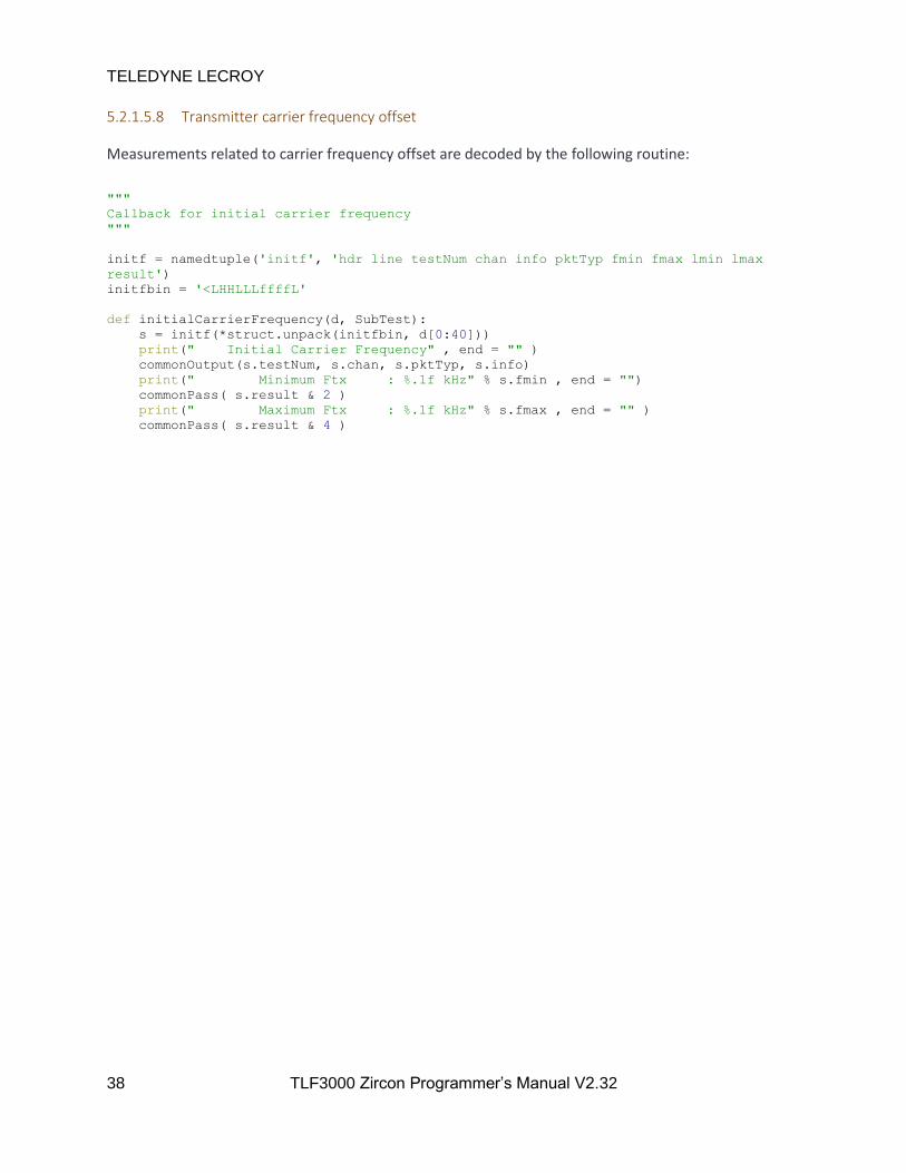
5.2.1.5.8 Transmitter carrier frequency offset
Measurements related to carrier frequency offset are decoded by the following routine:
"""
Callback for initial carrier frequency
"""
initf = namedtuple('initf', 'hdr line testNum chan info pktTyp fmin fmax lmin lmax
result')
initfbin = '<LHHLLLffffL'
def initialCarrierFrequency(d, SubTest):
s = initf(*struct.unpack(initfbin, d[0:40]))
print(" Initial Carrier Frequency" , end = "" )
commonOutput(s.testNum, s.chan, s.pktTyp, s.info)
print(" Minimum Ftx : %.1f kHz" % s.fmin , end = "")
commonPass( s.result & 2 )
print(" Maximum Ftx : %.1f kHz" % s.fmax , end = "" )
commonPass( s.result & 4 )
TELEDYNE LECROY
39 TLF3000 Zircon Programmer’s Manual V2.32
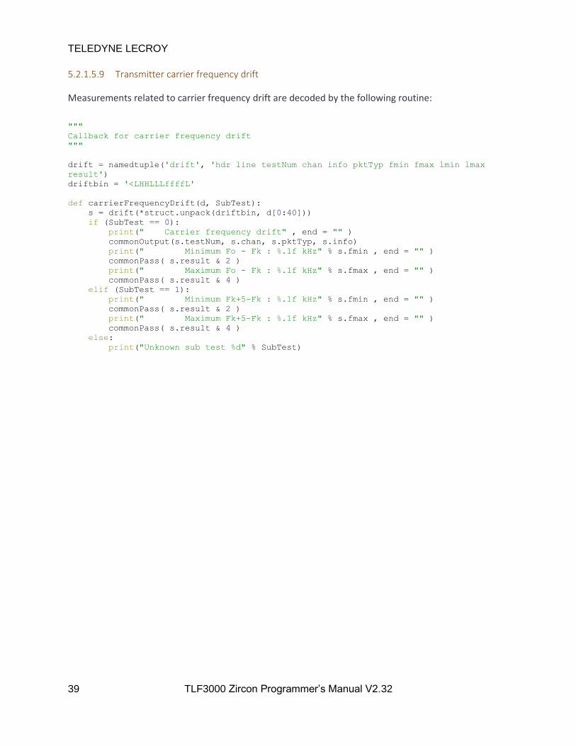
5.2.1.5.9 Transmitter carrier frequency drift
Measurements related to carrier frequency drift are decoded by the following routine:
"""
Callback for carrier frequency drift
"""
drift = namedtuple('drift', 'hdr line testNum chan info pktTyp fmin fmax lmin lmax
result')
driftbin = '<LHHLLLffffL'
def carrierFrequencyDrift(d, SubTest):
s = drift(*struct.unpack(driftbin, d[0:40]))
if (SubTest == 0):
print(" Carrier frequency drift" , end = "" )
commonOutput(s.testNum, s.chan, s.pktTyp, s.info)
print(" Minimum Fo - Fk : %.1f kHz" % s.fmin , end = "" )
commonPass( s.result & 2 )
print(" Maximum Fo - Fk : %.1f kHz" % s.fmax , end = "" )
commonPass( s.result & 4 )
elif (SubTest == 1):
print(" Minimum Fk+5-Fk : %.1f kHz" % s.fmin , end = "" )
commonPass( s.result & 2 )
print(" Maximum Fk+5-Fk : %.1f kHz" % s.fmax , end = "" )
commonPass( s.result & 4 )
else:
print("Unknown sub test %d" % SubTest)

TELEDYNE LECROY
40 TLF3000 Zircon Programmer’s Manual V2.32
5.2.1.5.10 Transmitter EDR relative transmit power
Measurements related to EDR relative transmit power are decoded by the following routine:
"""
Callback for tx EDR relative transmit power
"""
edrrelpow = namedtuple('edrrelpow', 'hdr line testNum chan info pktTyp pmin pmax lmin
lmax result')
edrrelpowbin = '<LHHLLLffffL'
def edrRelativeTransmitPower(d, SubTest):
s = edrrelpow(*struct.unpack(edrrelpowbin, d[0:40]))
print(" EDR relative tansmit power" , end = "" )
commonOutput(s.testNum, s.chan, s.pktTyp, s.info)
print(" Min PDPSK-PGSFK : %.1f dBm" % s.pmin , end = "" )
commonPass( s.result & 2 )
print(" Max PDPSK-PGSFK : %.1f dBm" % s.pmax , end = "" )
commonPass( s.result & 4 )

TELEDYNE LECROY
41 TLF3000 Zircon Programmer’s Manual V2.32
5.2.1.5.11 Transmitter EDR carrier frequency stability and modulation accuracy
Measurements related to EDR carrier frequency stability and modulation accuracy are decoded by the
following routine:
"""
Callback for tx EDR carrier frequency stability and modulation accuracy
"""
edrmod = namedtuple('edrmod', 'hdr line testNum chan info pktTyp pmin pmax lmin lmax
result')
edrmodbin = '<LHHLLLffffL'
def edrCarrierFrequencyStabilityAndModulationAccuracy(d, SubTest):
s = edrmod(*struct.unpack(edrmodbin, d[0:40]))
if (SubTest == 1):
print(" EDR Carrier frequency stability & modulation accuracy" , end = "")
commonOutput(s.testNum, s.chan, s.pktTyp, s.info)
print(" RMS DEVM : %.3f" % s.pmax , end = "" )
commonPass( s.result )
elif (SubTest == 2):
print(" Peak DEVM : %.3f" % s.pmax , end = "" )
commonPass( s.result )
elif (SubTest == 4):
print(" DEVM < Limit : %.3f%%" % s.pmin , end = "" )
commonPass( s.result )
elif (SubTest == 5):
print(" DEVM 99%% : %.3f" % s.pmax , end = "" )
commonPass( s.result )
elif (SubTest == 6): # Fo
pass
elif (SubTest == 7):
print(" Minimum wi : %.1f kHz" % s.pmin , end = "" )
commonPass( s.result & 2 )
print(" Maximum wi : %.1f kHz" % s.pmax , end = "" )
commonPass( s.result & 4 )
elif (SubTest == 8):
print(" Minimum wo : %.1f kHz" % s.pmin , end = "" )
commonPass( s.result & 2 )
print(" Maximum wo : %.1f kHz" % s.pmax , end = "" )
commonPass( s.result & 4 )
elif (SubTest == 9):
print(" Minimum wi - wo : %.1f kHz" % s.pmin , end = "" )
commonPass( s.result & 2 )
print(" Maximum wi - wo : %.1f kHz" % s.pmax , end = "" )
commonPass( s.result & 4 )
else:
print("Unknown sub test %d" % SubTest)
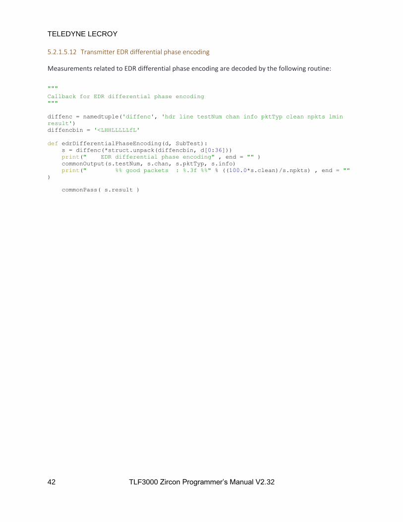
TELEDYNE LECROY
42 TLF3000 Zircon Programmer’s Manual V2.32
5.2.1.5.12 Transmitter EDR differential phase encoding
Measurements related to EDR differential phase encoding are decoded by the following routine:
"""
Callback for EDR differential phase encoding
"""
diffenc = namedtuple('diffenc', 'hdr line testNum chan info pktTyp clean npkts lmin
result')
diffencbin = '<LHHLLLLLfL'
def edrDifferentialPhaseEncoding(d, SubTest):
s = diffenc(*struct.unpack(diffencbin, d[0:36]))
print(" EDR differential phase encoding" , end = "" )
commonOutput(s.testNum, s.chan, s.pktTyp, s.info)
print(" %% good packets : %.3f %%" % ((100.0*s.clean)/s.npkts) , end = ""
)
commonPass( s.result )

TELEDYNE LECROY
43 TLF3000 Zircon Programmer’s Manual V2.32
5.2.1.5.13 Transmitter EDR in-band spurious emissions
Measurements related to EDR in-band spurious emissions are decoded by the following routine. Two
spectra are returned. The first contains the ACP measurements every 1MHz from 2395MHz to 2485MHz
inclusive. The second contains the 100kHz RBW measurements which were used to generate the 1MHz
resolution results. These measurements are from 2394.550MHz to 2485.450MHz in 100kHz steps.
"""
Callback for EDR in-band spurious emissions
"""
edracp = namedtuple('edracp', 'hdr line testNum chan info pktTyp pmin pmax lmin lmax
result')
edracpbin = '<LHHLLLffffL'
def edrInBandSpuriousEmissions(d, SubTest):
global oldSubTest
if (SubTest == 1):
s = edracp(*struct.unpack(edracpbin, d[0:40]))
print(" | M - N | = 2 : %.1f dBm" % s.pmax , end = "" )
commonPass( s.result & 1 )
elif (SubTest == 2):
s = edracp(*struct.unpack(edracpbin, d[0:40]))
print(" | M - N | >= 3 : %.1f dBm" % s.pmax , end = "" )
commonPass( s.result & 1 )
elif (SubTest == 3):
s = edracp(*struct.unpack(edracpbin, d[0:40]))
if (oldSubTest != 4):
print(" EDR in-band spurious emissions" , end = "" )
commonOutput(s.testNum, s.chan, s.pktTyp, s.info)
print(" # exceptions : %.0f" % s.pmax , end = "" )
commonPass( s.result & 1 )
elif (SubTest == 4):
s = edracp(*struct.unpack(edracpbin, d[0:40]))
print(" EDR in-band spurious emissions" , end = "" )
commonOutput(s.testNum, s.chan, s.pktTyp, s.info)
print(" Max exception : %.1f dBm" % s.pmax , end = "" )
commonPass( s.result & 1 )
elif (SubTest == 5):
spectrum = struct.unpack( '91f' , d[20:384] )
print("Spectrum",spectrum)
elif (SubTest == 0):
s = edracp(*struct.unpack(edracpbin, d[0:40]))
print(" PTXref - PTX : %.1f dBm" % s.pmax , end = "" )
commonPass( s.result & 1 )
elif (SubTest == 6):
spectrum = struct.unpack( '910f' , d[20:3660] )
print("Spectrum",spectrum)
else:
print("Unknown sub test %d" % SubTest)
oldSubTest = SubTest
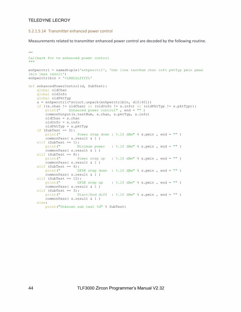
TELEDYNE LECROY
44 TLF3000 Zircon Programmer’s Manual V2.32
5.2.1.5.14 Transmitter enhanced power control
Measurements related to transmitter enhanced power control are decoded by the following routine.
"""
Callback for tx enhanced power control
"""
enhpwrctrl = namedtuple('enhpwrctrl', 'hdr line testNum chan info pktTyp pmin pmax
lmin lmax result')
enhpwrctrlbin = '<LHHLLLffffL'
def enhancedPowerControl(d, SubTest):
global oldChan
global oldInfo
global oldPktTyp
s = enhpwrctrl(*struct.unpack(enhpwrctrlbin, d[0:40]))
if ((s.chan != oldChan) or (oldInfo != s.info) or (oldPktTyp != s.pktTyp)):
print(" Enhanced power control" , end = "" )
commonOutput(s.testNum, s.chan, s.pktTyp, s.info)
oldChan = s.chan
oldInfo = s.info
oldPktTyp = s.pktTyp
if (SubTest == 0):
print(" Power step down : %.1f dBm" % s.pmin , end = "" )
commonPass( s.result & 1 )
elif (SubTest == 1):
print(" Minimum power : %.1f dBm" % s.pmin , end = "" )
commonPass( s.result & 1 )
elif (SubTest == 8):
print(" Power step up : %.1f dBm" % s.pmin , end = "" )
commonPass( s.result & 1 )
elif (SubTest == 4):
print(" GFSK step down : %.1f dBm" % s.pmin , end = "" )
commonPass( s.result & 1 )
elif (SubTest == 12):
print(" GFSK step up : %.1f dBm" % s.pmin , end = "" )
commonPass( s.result & 1 )
elif (SubTest == 3):
print(" Start/End diff : %.1f dBm" % s.pmin , end = "" )
commonPass( s.result & 1 )
else:
print("Unknown sub test %d" % SubTest)
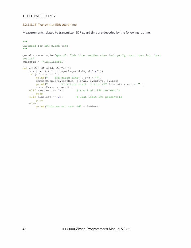
TELEDYNE LECROY
45 TLF3000 Zircon Programmer’s Manual V2.32
5.2.1.5.15 Transmitter EDR guard time
Measurements related to transmitter EDR guard time are decoded by the following routine.
"""
Callback for EDR guard time
"""
guard = namedtuple('guard', 'hdr line testNum chan info pktTyp tmin tmax lmin lmax
result')
guardbin = '<LHHLLLffffL'
def edrGuardTime(d, SubTest):
s = guard(*struct.unpack(guardbin, d[0:40]))
if (SubTest == 0):
print(" EDR guard time" , end = "" )
commonOutput(s.testNum, s.chan, s.pktTyp, s.info)
print(" %% within limit : %.3f %%" % s.tmin , end = "" )
commonPass( s.result )
elif (SubTest == 1): # Low limit 99% percentile
pass
elif (SubTest == 2): # High limit 99% percentile
pass
else:
print("Unknown sub test %d" % SubTest)

TELEDYNE LECROY
46 TLF3000 Zircon Programmer’s Manual V2.32
5.2.1.5.16 Transmitter EDR synchronisation sequence and trailer
Measurements related to EDR synchronisation sequence and trailer are decoded by the following
routine.
"""
Callback for EDR synchronisation sequence and trailer
"""
synctrail = namedtuple('synctrail', 'hdr line testNum chan info pktTyp pmax lmax
result')
synctrailbin = '<LHHLLLffL'
def edrSynchronisationSequenceAndTrailer(d, SubTest):
s = synctrail(*struct.unpack(synctrailbin, d[0:32]))
if (SubTest == 0):
print(" EDR synchronisation sequence & trailer" , end = "" )
commonOutput(s.testNum, s.chan, s.pktTyp, s.info)
print(" Sync sequence BER : %.3f %%" % (100.0*s.pmax) , end = "" )
commonPass( s.result )
elif (SubTest == 1):
print(" Trailer BER : %.3f %%" % (100.0*s.pmax) , end = "" )
commonPass( s.result )
else:
print("Unknown sub test %d" % SubTest)

TELEDYNE LECROY
47 TLF3000 Zircon Programmer’s Manual V2.32
5.2.1.6 Receiver test results
Receiver test results are directed through a single routine called by the main asynchronous callback
handler. The nature of the receiver test is determined and an appropriate routine for handling the
asynchronous data is called.
"""
Dictionary to map test numbers to callbacks
"""
rxType =
1: sensitivity,
2: sensitivity,
3: ciPerformance,
4: blocking,
5: intermodulation,
6: sensitivity,
7: sensitivity,
8: sensitivity,
9: ciPerformance,
10: sensitivity
"""
Callbacks for handling receive messages
These are passed to the appropraite message handler
"""
rxhdr = namedtuple('rxhdr', 'hdr line testNum')
rxhdrbin = '<LHH'
def rxTest(d):
s = rxhdr(*struct.unpack(rxhdrbin, d[0:8]))
SubTest = s.testNum >> 12;
TestNum = (s.testNum >> 4) & 0xFF;
rxType.get( TestNum )(d,SubTest,rxTitles[TestNum])
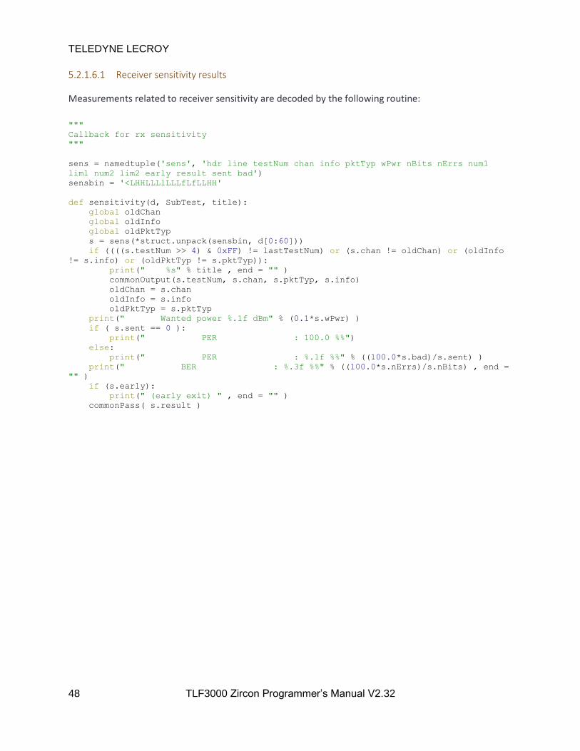
TELEDYNE LECROY
48 TLF3000 Zircon Programmer’s Manual V2.32
5.2.1.6.1 Receiver sensitivity results
Measurements related to receiver sensitivity are decoded by the following routine:
"""
Callback for rx sensitivity
"""
sens = namedtuple('sens', 'hdr line testNum chan info pktTyp wPwr nBits nErrs num1
lim1 num2 lim2 early result sent bad')
sensbin = '<LHHLLLlLLLfLfLLHH'
def sensitivity(d, SubTest, title):
global oldChan
global oldInfo
global oldPktTyp
s = sens(*struct.unpack(sensbin, d[0:60]))
if ((((s.testNum >> 4) & 0xFF) != lastTestNum) or (s.chan != oldChan) or (oldInfo
!= s.info) or (oldPktTyp != s.pktTyp)):
print(" %s" % title , end = "" )
commonOutput(s.testNum, s.chan, s.pktTyp, s.info)
oldChan = s.chan
oldInfo = s.info
oldPktTyp = s.pktTyp
print(" Wanted power %.1f dBm" % (0.1*s.wPwr) )
if ( s.sent == 0 ):
print(" PER : 100.0 %%")
else:
print(" PER : %.1f %%" % ((100.0*s.bad)/s.sent) )
print(" BER : %.3f %%" % ((100.0*s.nErrs)/s.nBits) , end =
"" )
if (s.early):
print(" (early exit) " , end = "" )
commonPass( s.result )

TELEDYNE LECROY
49 TLF3000 Zircon Programmer’s Manual V2.32
5.2.1.6.2 Receiver C/I results
Measurements related to receiver C/I measurements are decoded by the following routine:
"""
Callback for rx C/I messages
"""
interference = namedtuple('interference', 'hdr line testNum chan info pktTyp wPwr
iChan iPwr nBits nErrs num1 lim1 num2 lim2 early result sent bad')
interferencebin = '<LHHLLLlLlLLLfLfLLHH'
exception = namedtuple('exception', 'hdr line testNum chan info pktTyp wPwr nXcep
maxXcep lvlXcep result')
exceptionbin = '<LHHLLLlLLlL'
def ciPerformance(d, SubTest, title):
global lastTestNum
global oldChan
global oldInfo
global oldPktTyp
global oldIchan
if (SubTest == 0):
s = interference(*struct.unpack(interferencebin, d[0:68]))
if ((((s.testNum >> 4) & 0xFF) != lastTestNum) or (s.chan != oldChan) or
(s.iChan != oldIchan) or (oldInfo != s.info) or (oldPktTyp != s.pktTyp)):
commonOutputInterferer(s.testNum, s.chan, s.iChan, s.pktTyp, s.info, 0)
oldChan = s.chan
oldIchan = s.iChan
oldInfo = s.info
oldPktTyp = s.pktTyp
print(" Wanted power %.1f dBm" % (0.1*s.wPwr))
print(" Interferer power %.1f dBm" % (0.1*s.iPwr))
if ( s.sent == 0 ):
print(" PER : 100.0 %%")
else:
print(" PER : %.1f %%" % ((100.0*s.bad)/s.sent) )
print(" BER : %.3f %%" % ((100.0*s.nErrs)/s.nBits) ,
end = "" )
if (s.early):
print(" (early exit) " , end = "")
if( s.result == 0 ):
print(" ( PASS )" )
elif( s.result == 2 ):
print(" ( EXCEPTION )")
else:
print(" ( FAIL )")
elif( SubTest == 8 ):
s = exception(*struct.unpack(exceptionbin, d[0:40]))
print(" Number of exceptions %d" % s.nXcep , end = "" )
commonPass( s.result )
else:
print("Unknown sub test %d" % SubTest)

TELEDYNE LECROY
50 TLF3000 Zircon Programmer’s Manual V2.32
5.2.1.6.3 Receiver blocking results
Measurements related to receiver blocking performance are decoded by the routine:
"""
Callback for rx blocking messages
"""
blocking = namedtuple('blocking', 'hdr line testNum chan info pktTyp wPwr MHz iPwr
nBits nErrs num1 lim1 num2 lim2 early result sent bad')
blockingbin = '<LHHLLLlLlLLLfLfLLHH'
def blocking(d, SubTest, title):
global lastTestNum
global oldChan
global oldMHz
global oldInfo
global oldPktTyp
if (SubTest == 0):
s = blocking(*struct.unpack(blockingbin, d[0:68]))
if ((((s.testNum >> 4) & 0xFF) != lastTestNum) or (s.chan != oldChan) or
(s.MHz != oldMHz) or (oldInfo != s.info) or (oldPktTyp != s.pktTyp)):
print(" Blocking" , end = "" )
commonOutputInterferer(s.testNum, s.chan, s.MHz, s.pktTyp, s.info, 1)
oldChan = s.chan
oldMHz = s.MHz
oldInfo = s.info
oldPktTyp = s.pktTyp
print(" Wanted power %.1f dBm" % (0.1*s.wPwr))
print(" Blocker power %.1f dBm" % (0.1*s.iPwr))
if ( s.sent == 0 ):
print(" PER : 100.0 %%")
else:
print(" PER : %.1f %%" % ((100.0*s.bad)/s.sent) )
print(" BER : %.3f %%" % ((100.0*s.nErrs)/s.nBits) ,
end = "" )
if (s.early):
print(" (early exit) " , end = "" )
if (s.result == 0):
print(" ( PASS )")
elif (s.result == 2):
print(" ( EXCEPTION - higher level )")
elif (s.result == 4):
print(" ( EXCEPTION - lower level )");
else:
print(" ( FAIL )")
elif (SubTest == 8):
s = exception(*struct.unpack(exceptionbin, d[0:40]))
print(" Number of exceptions %d" % s.nXcep , end = "" )
commonPass( s.result )
elif (SubTest == 4):
s = exception(*struct.unpack(exceptionbin, d[0:40]))
print(" Number of failures %d" % s.nXcep , end = "" )
commonPass( s.result )
else:
print("Unknown sub test %d" % SubTest)

TELEDYNE LECROY
51 TLF3000 Zircon Programmer’s Manual V2.32
5.2.1.6.4 Receiver intermodulation results
Measurements related to the receiver intermodulation performance are handled by the following
routine:
"""
Callback for rx intermodulation messages
"""
intermod = namedtuple('intermod', 'hdr line testNum chan info pktTyp wPwr n iPwr nBits
nErrs num1 lim1 num2 lim2 early result sent bad')
intermodbin = '<LHHLLLlLlLLLfLfLLHH'
def intermodulation(d, SubTest, title):
global lastTestNum
global oldChan
global oldN
global oldInfo
global oldPktTyp
s = intermod(*struct.unpack(intermodbin, d[0:68]))
if ((((s.testNum >> 4) & 0xFF) != lastTestNum) or (s.chan != oldChan) or (s.n !=
oldN) or (oldInfo != s.info) or (oldPktTyp != s.pktTyp)):
print(" Intermodulation" , end = "" )
commonOutputInterferer(s.testNum, s.chan, s.n, s.pktTyp, s.info, 2)
oldChan = s.chan;
oldN = s.n;
oldInfo = s.info;
oldPktTyp = s.pktTyp;
print(" Wanted power %.1f dBm" % (0.1*s.wPwr))
print(" Interferer power %.1f dBm" % (0.1*s.iPwr))
if ( s.sent == 0 ):
print(" PER : 100.0 %%")
else:
print(" PER : %.1f %%" % ((100.0*s.bad)/s.sent) )
print(" BER : %.3f %%" % ((100.0*s.nErrs)/s.nBits) ,
end= "" )
if (s.early):
print(" (early exit) " , end = "" )
commonPass( s.result )

TELEDYNE LECROY
52 TLF3000 Zircon Programmer’s Manual V2.32
5.2.2 Programming the signal generator
This example code demonstrates how to program the various signal generator sources and then turn on
the signal generator output.
The sequence of operations is as follows:
1. A connection is made to the wanted TLF3000 unit using the connection code described in
Connecting to the TLF3000
2. The Zircon application is launched using the code described in Launching the Zircon application
3. A callback for asynchronous messages is registered using the code described in Handling
asynchronouos data
4. The operating mode is set to signal generator mode using setMode
5. Set the cable loss using setCableLoss
6. Vectors are created to hold the dirty transmitter table. In this example, the dirty transmitter
table contains two rows.
7. The wanted signal is programmed using progWanted. At this stage there is not output from the
signal generator since it has not been started.
8. An interferer signal is programmed using progInterferer
9. An in-band CW blocker is programmed using progCW
10. A second in-band CW blocker is programmed using progCW
11. An AWGN source is enabled using progAWGN
12. An out–of-band CW blocker is programmed using progOutOfBandCW
13. The signal generator is started by calling startSigGen. It is only at this point that the signal
generator starts outputting power.
14. Once the programmed number of wanted packets have been transmitted, the signal generator
is stopped by calling stopSigGen. This does not affect the programming which has previously
been performed.

"""
Main script
"""
if __name__ == '__main__':
global done
transport = connect() # Connect to the TLF3000 unit
zircon = ZirconInterface(transport) # Launch the Zircon application
zircon.setDataCallback(dataCallback,False) # Register callback for asynch data channel
if( not zircon.setMode( 1 ) ): # Enter signal generator mode
getError(zircon)
if( not zircon.setCableLoss( 0.0 ) ): # Set cable loss in units of dB
getError(zircon)
# Distortion table for wanted signal - an empty vector will
# apply no distortions
# carrier offset in kHZ
# modulation index x 10000
# drift magnitude in kHz
# drift rate in Hz
# symbol timing error in ppm
distortions = vector_int16( array.array( "h" ,( 0, 3200, 0, 0, 0,
50, 3200, 0, 0, 0 ) ) )
distortions = vector_int16( array.array( "h" , () ) )
# Program the wanted signal
# Arg1 : True = on, False = off
# Arg2 : RF channel, 0 -> 78
# Arg3 : Amplitude in dBm
# Arg4 : phy, 0 = BR, 1 = 2-EDR, 2 = 3-EDR
# Arg5 : UAP - 8bits
# Arg6 : True = whiten, False = do not whiten
# Arg7 : Central clock, LSB used for whitening, ignored if
# whitening disabled
# Arg8 : LAP - 24bits
# Arg9 : Header contents without HEC - 10bits, but the
# packet type bits are ignored and set on the basis
# of Arg11
# Arg10: Payload header - numbers of bits dependent on
# packet type, those bits which denote the number of
# octets are ignored and are set on the basis of
# Arg21

TELEDYNE LECROY
54 TLF3000 Zircon Programmer’s Manual V2.32
# Arg11: Packet type
# 0 = ID
# 1 = NULL
# 2 = POLL
# 3 = FHS
# 4 = DM1
# 5 = DH1
# 6 = DM3
# 7 = DH3
# 8 = DM5
# 9 = DH5
# 10 = AUX1
# 11 = 2-DH1
# 12 = 2-DH3
# 13 = 2-DH5
# 14 = 3-DH1
# 15 = 3-DH3
# 16 = 3-DH5
# 17 = HV1
# 18 = HV2
# 19 = HV3
# 20 = DV
# 21 = EV3
# 22 = EV4
# 23 = EV5
# 24 = 2-EV3
# 25 = 2-EV5
# 26 = 3-EV3
# 27 = 3-EV5
# Arg12: Payload type
# 0 = PRBS9
# 1 = PRBS11
# 2 = PRBS15
# 3 = PRBS20
# 4 = PRBS23
# 5 = PRBS29
# 6 = PRBS31
# 7 = 00001111
# 8 = 01010101
# 9 = 11111111
# 10 = 00000000
# 11 = 11110000
# 12 = 10101010
# Arg13: adjustment to guard interval in us
# Arg14: relative amplitude of EDR re GFSK in dB

TELEDYNE LECROY
55 TLF3000 Zircon Programmer’s Manual V2.32
# Arg15: number of packets to send, 0 => infinite
# Arg16: interval between packets in us
# Arg17: ramp time in us
# Arg18: length of unmodulated carrier prior to preamble in
# us
# Arg19: length of unmodulated carrier after CRC and prior
# to ramp down in us
# Arg20: number of octets in payload
print( "Program wanted signal" )
if( not zircon.progWanted( True, 10, -20, 2, 0x7D, False, 0x00, 0xE78F12, 0x00, 0x00, 16, 7, 0.0, -2.0, 1000,
6*625, 2.0, 2.0, 2.0, 1021, distortions ) ):
getError(zircon)
# Program interferer signal
# Arg1 : True = on, False = off
# Arg2 : True = continuous transmission,
# False = packetised transmission
# Arg3 : Amplitude in dBm
# Arg4 : phy, 0 = BR, 1 = 2-EDR, 2 = 3-EDR
# Arg5 : Number of octets in payload for packetised
# transmission, ignored otherwise
# Arg6 : Frequency of transmission in MHz
# Arg7 : Period between packets in us for packetised
# transmission, ignored otherwise
print( "Program interferer" )
if( not zircon.progInterferer( True, False, -15, 0, 27, 2460, 2*625 ) ):
getError(zircon)
# Program first CW
# Arg1 : Number of CW interferer to program
# Arg2 : True = on, False = off
# Arg3 : Amplitude in dBm
# Arg4 : Frequency in Hz
print( "Program first CW signal" )
if( not zircon.progCW( 0, True, -40, 2451000 ) ):
getError(zircon)
# Program second CW
print( "Program seond CW signal" )
if( not zircon.progCW( 1, True, -40, 2421000 ) ):
getError(zircon)
# Program AWGN
# Arg1 : True = on, False = off
# Arg2 : Amplitude in dBm/MHz

TELEDYNE LECROY
56 TLF3000 Zircon Programmer’s Manual V2.32
print( "Program AWGN" )
if( not zircon.progAWGN( True , -45 ) ):
getError(zircon)
# Program out-of-band CW
# Arg1 : True = on, False = off
# Arg2 : Amplitude in dBm
# Arg3 : Frequency in MHz
print( "Program out-of-band CW" )
if( not zircon.progOutOfBandCW( True, -30, 2441 ) ):
getError(zircon)
# Start the signal geneator
print( "Start signal generator" )
done = False
if( not zircon.startSigGen() ):
getError(zircon)
print( "Waiting for signal generator to send wanted packets" )
while not done:
sleep(0.1)
getError(zircon)
# Stop the signal generator
print( "Stop signal generator" )
if( not zircon.stopSigGen() ):
getError(zircon)
zircon.exitApp() # Close the Zircon applications
zircon = 0
transport = 0
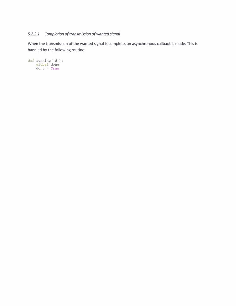
5.2.2.1 Completion of transmission of wanted signal
When the transmission of the wanted signal is complete, an asynchronous callback is made. This is
handled by the following routine:
def running( d ):
global done
done = True

TELEDYNE LECROY
58 TLF3000 Zircon Programmer’s Manual V2.32
5.2.3 Analysing waveforms using the signal analyser
This example code demonstrates how to program the signal analyser and instruct it to run. Various
results are then retrieved from the signal analyser.
The sequence of operations is as follows:
1. A connection is made to the wanted TLF3000 unit using the connection code described in
Connecting to the TLF3000
2. The Zircon application is launched using the code described in Launching the Zircon application
3. A callback for asynchronous messages is registered using the code described in Handling
asynchronouos data
4. The operating mode is set to signal analyser mode using setMode
5. The receiver port to be used is set using setRxPort
6. The receiver frontend attenuation is set using setRxAtten
7. The cable loss is set using setCableLoss
8. There then follows a section of optional code which creates an over-the-air connection to a DUT
and instructs it to transmit. See Controlling a DUT over-the-air for further details on how to
connect to a DUT over-the-air.
9. The signal analayser is set running using startSigAna.
10. After 10 seconds the signal analyser is halted using stopSigAna. It is not actually neceassry to
stop the signal analyser running before reading back results.
11. pollSigAnaTable is used to recover the output power results table and then further calls are used
to recover the modulation characteristics, carrier frequency and drift results table and the
spectral results table. All these tables are printed out.

"""
routine for printing results tables
"""
PowerHeadingsBR = (
"Pavg",
"Pk-Pavg"
)
PowerHeadingsEDR = (
"Pavg",
"EDR re GFSK",
"Guard- 99%",
"Guard+ 99%",
"Guard > 4.6",
"Guard < 5.4"
)
ModulationHeadingsBR = (
"DF1max",
"DF1avg",
"DF2max",
"DF2avg",
"DF2avg/DF1avg",
"DF2max 99.9%",
"DF2max > 115"
)
ModulationHeadingsEDR = (
"RMS DEVM",
"PK DEVM",
"DEVM <= 30%",
"DEVM 99%"
)
DriftHeadingsBR = (
"Fo",
"Fk+5 - Fk",
"1 slot Fo - Fk",
"3 slot Fo - Fk",
"5 slot Fo - Fk"
)
DriftHeadingsEDR = (
"Wi",
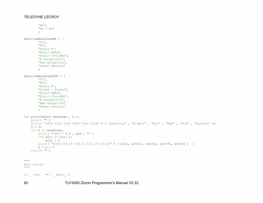
TELEDYNE LECROY
60 TLF3000 Zircon Programmer’s Manual V2.32
"Wo",
"Wi + Wo"
)
SpectrumHeadingsBR = (
"Fl",
"Fh",
"Delta F",
"Ftx+/-2MHz",
"Ftx+/-(3+n)MHz",
"# exceptions",
"Max exception",
"Power density"
)
SpectrumHeadingsEDR = (
"Fl",
"Fh",
"Delta F",
"Ptx26 - Ptxref",
"Ftx+/-2MHz",
"Ftx+/-(3+n)MHz",
"# exceptions",
"Max exception",
"Power density"
)
def printTable( headings , x ):
print( "" )
print( "%20s %10s %10s %10s %10s %10s" % ( "Quantity" , "# Pkts" , "Min" , "Max" , "Avg" , "Current" ))
n = 0;
for h in headings:
print( "%20s " % h , end = "" )
if( x[n] != x[n] ):
x[n] = 0
print( "%10d %10.1f %10.1f %10.1f %10.1f" % ( x[n], x[n+1], x[n+2], x[n+3], x[n+4] ) )
n = n + 5
print( "" )
"""
Main script
"""
if __name__ == '__main__':
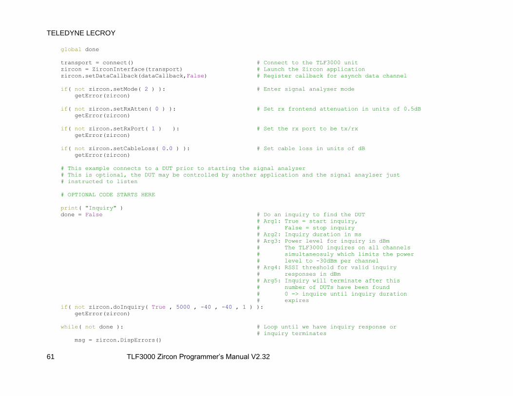
TELEDYNE LECROY
61 TLF3000 Zircon Programmer’s Manual V2.32
global done
transport = connect() # Connect to the TLF3000 unit
zircon = ZirconInterface(transport) # Launch the Zircon application
zircon.setDataCallback(dataCallback,False) # Register callback for asynch data channel
if( not zircon.setMode( 2 ) ): # Enter signal analyser mode
getError(zircon)
if( not zircon.setRxAtten( 0 ) ): # Set rx frontend attenuation in units of 0.5dB
getError(zircon)
if( not zircon.setRxPort( 1 ) ): # Set the rx port to be tx/rx
getError(zircon)
if( not zircon.setCableLoss( 0.0 ) ): # Set cable loss in units of dB
getError(zircon)
# This example connects to a DUT prior to starting the signal analyser
# This is optional, the DUT may be controlled by another application and the signal anaylser just
# instructed to listen
# OPTIONAL CODE STARTS HERE
print( "Inquiry" )
done = False # Do an inquiry to find the DUT
# Arg1: True = start inquiry,
# False = stop inquiry
# Arg2: Inquiry duration in ms
# Arg3: Power level for inquiry in dBm
# The TLF3000 inquires on all channels
# simultaneosuly which limits the power
# level to -30dBm per channel
# Arg4: RSSI threshold for valid inquiry
# responses in dBm
# Arg5: Inquiry will terminate after this
# number of DUTs have been found
# 0 => inquire until inquiry duration
# expires
if( not zircon.doInquiry( True , 5000 , -40 , -40 , 1 ) ):
getError(zircon)
while( not done ): # Loop until we have inquiry response or
# inquiry terminates
msg = zircon.DispErrors()
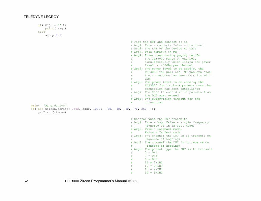
TELEDYNE LECROY
62 TLF3000 Zircon Programmer’s Manual V2.32
if( msg != "" ):
print( msg )
else:
sleep(0.1)
# Page the DUT and connect to it
# Arg1: True = connect, False = disconnect
# Arg2: The LAP of the device to page
# Arg3: Page timeout in ms
# Arg4: Power used during paging in dBm
# The TLF3000 pages on channels
# simultaneously which limits the power
# level to -30dBm per channel
# Arg5: The power level to be used by the
# TLF3000 for poll and LMP packets once
# the connection has been established in
# dBm
# Arg6: The power level to be used by the
# TLF3000 for loopback packets once the
# connection has been established
# Arg7: The RSSI threshold which packets from
# the DUT must exceed
# Arg8: The supervision timeout for the
# connection
print( "Page device" )
if( not zircon.doPage( True, addr, 10000, -40, -40, -40, -70, 250 ) ):
getError(zircon)
# Control what the DUT transmits
# Arg1: True = hop, False = single frequency
# (ignored if in Tx Test mode)
# Arg2: True = Loopback mode,
# False = Tx Test mode
# Arg3: The channel the DUT is to transmit on
# (ignored if hopping)
# Arg4: The channel the DUT is to receive on
# (ignored if hopping)
# Arg5: The packet type the DUT is to transmit
# 5 = DH1
# 7 = DH3
# 9 = DH5
# 11 = 2-DH1
# 12 = 2-DH3
# 13 = 2=DH5
# 14 = 3-DH1

TELEDYNE LECROY
63 TLF3000 Zircon Programmer’s Manual V2.32
# 15 = 3-DH3
# 16 = 3-DH5
# Arg6: The power the TLF3000 is to transmit
# poll packets at in dBm
# Arg7: The power the TLF3000 is to transmit
# loopback packets at in dBm
# Arg8: The number of octets in the packets to
# be transmitted by the DUT
# Arg9: The payload of the packets to be
# transmsitted by the DUT
# 0 = PRBS9
# 1 = 11110000
# 2 = 10101010
# 3 = 11111111
# 4 = 00000000
# Arg10:True = whitening on,
# False = whitening off
print( "Program DUT transmissions" )
if( not zircon.progLoopback( False, True, 0, 78, 11, -40, -40, 27, 0, False ) ):
getError( zircon )
# Control the DUT output power
# 1 = increment power
# 2 = maximum power
# 255 = decrement power
# 254 = minimum power
print( "Set DUT power" )
if( not zircon.pwrControl( 2 ) ):
getError( zircon )
# Change the level of poll packets sent by the TLF3000
print( "Set TLF3000 power" )
if( not zircon.setPollPwr( -50 ) ):
getError( zircon );
# Change the level of loopback packets sent by
# the TLF3000 (ignored in Tx Test mode)
if( not zircon.setLoopPwr( -50 ) ):
getError( zircon )
# OPTIONAL CODE ENDS HERE
# Start the signal analyser
# Arg 1 : Supervision timeout in ms, ignored
# if no DUT is being controlled

TELEDYNE LECROY
64 TLF3000 Zircon Programmer’s Manual V2.32
# Arg 2 : RSSI threshold for packets to be
# analysed
print( "Start signal analyser" )
if( not zircon.startSigAna( 250, -70 ) ):
getError(zircon)
# Wait for the signal analyser to collect data
sleep(10)
# Stop the signal analyser
# Signal analyer can be stopped before or after
# printing results
print( "Stop signal analyser" )
if( not zircon.stopSigAna() ):
getError(zircon)
"""
Output power results
"""
# Poll results table
# Arg1: measurement to be retrieved
# Arg2: bit mask for channel filter
# bitn = RF channel number n
# Arg3: bit mask for phy filter
# bit0 = BR
# bit1 = 2-EDR
# bit2 = 3-EDR
# Arg4: bit mask for packet slots
# bit0 = 1 slot packets
# bit1 = 3 slot packets
# bit2 = 5 slot packets
chans = vector_uchar( array.array( "B" , ( 0xFF , 0xFF , 0xFF , 0xFF , 0xFF , 0xFF ,
0xFF , 0xFF , 0xFF , 0x7F ) ) )
x = zircon.pollSigAnaTable( 0, chans, 0x2 , 0x7 )
if( len(x) == 10 ):
printTable( PowerHeadingsBR , x )
else:
printTable( PowerHeadingsEDR , x )
"""
Output modulation characteristics
"""
# Poll results table
# Arg1: measurement to be retrieved
# Arg2: bit mask for channel filter
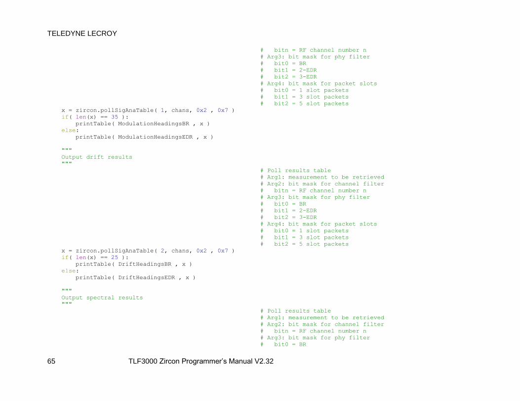
TELEDYNE LECROY
65 TLF3000 Zircon Programmer’s Manual V2.32
# bitn = RF channel number n
# Arg3: bit mask for phy filter
# bit0 = BR
# bit1 = 2-EDR
# bit2 = 3-EDR
# Arg4: bit mask for packet slots
# bit0 = 1 slot packets
# bit1 = 3 slot packets
# bit2 = 5 slot packets
x = zircon.pollSigAnaTable( 1, chans, 0x2 , 0x7 )
if( len(x) == 35 ):
printTable( ModulationHeadingsBR , x )
else:
printTable( ModulationHeadingsEDR , x )
"""
Output drift results
"""
# Poll results table
# Arg1: measurement to be retrieved
# Arg2: bit mask for channel filter
# bitn = RF channel number n
# Arg3: bit mask for phy filter
# bit0 = BR
# bit1 = 2-EDR
# bit2 = 3-EDR
# Arg4: bit mask for packet slots
# bit0 = 1 slot packets
# bit1 = 3 slot packets
# bit2 = 5 slot packets
x = zircon.pollSigAnaTable( 2, chans, 0x2 , 0x7 )
if( len(x) == 25 ):
printTable( DriftHeadingsBR , x )
else:
printTable( DriftHeadingsEDR , x )
"""
Output spectral results
"""
# Poll results table
# Arg1: measurement to be retrieved
# Arg2: bit mask for channel filter
# bitn = RF channel number n
# Arg3: bit mask for phy filter
# bit0 = BR

TELEDYNE LECROY
66 TLF3000 Zircon Programmer’s Manual V2.32
# bit1 = 2-EDR
# bit2 = 3-EDR
# Arg4: bit mask for packet slots
# bit0 = 1 slot packets
# bit1 = 3 slot packets
# bit2 = 5 slot packets
x = zircon.pollSigAnaTable( 3, chans, 0x2 , 0x7 )
if( len(x) == 40 ):
printTable( SpectrumHeadingsBR , x )
else:
printTable( SpectrumHeadingsEDR , x )
zircon.exitApp() # Close the Zircon applications
zircon = 0
transport = 0

5.2.4 Controlling a DUT over-the-air
This example code demonstrates how a DUT can be controlled from the Zircon application. This is
possible in either signal analyser or DUT control mode.
The sequence of operations is as follows:
1. A connection is made to the wanted TLF3000 unit using the connection code described in
Connecting to the TLF3000
2. The Zircon application is launched using the code described in Launching the Zircon application
3. A callback for asynchronous messages is registered using the code described in Handling
asynchronouos data
4. The operating mode is set to DUT control mode using setMode
5. The receiver port to be used is set using setRxPort
6. The receiver frontend attenuation is set using setRxAtten
7. The cable loss is set using setCableLoss
8. An inquiry is initiated by calling doInquiry. The Zircon application sends out inquiry packets on all
inquiry channels simultaneously. If the DUT inquiry scan activity to ensure the device listens
frequently, then the device will be found almost immediately. For every device which is found,
an asynchronous callback routine is executed.
9. When the inquiry has terminated, as indicated by an asynchronous callback, the Zircon
application pages and connects to the chosen device by calling doPage.
10. Once connected to the DUT, a call is made to progLoopback to determine what packets are
transmitted between the Zircon application and the DUT.
11. A call is made to pwrControl to tell the DUT to increase its transmitter power to maximum.
12. A call is made to setPollPwr to set the level at which the Zircon application transmits poll
packets to the DUT. These are transmitted in tx test mode or whenever the Zircon application
detects that the link is about to timeout.
13. A call is made to setLoopPwr to set the level at which the Zircon application transmits loopback
packets. These are the packets which are used when testing receiver sensitivity.
14. A call is made to setRSSIthreshold to set an RSSI threshold. Only those packets which have a
signal strength greated than the threshold will be analysed by the Zircon application. This can be
used in signal analyser mode to restrict the packets which are analysed to a nearby device.
15. Finally a second call is made to doPage to terminate the connection to the DUT.

"""
Main script
"""
if __name__ == '__main__':
global done
global addr
transport = connect() # Connect to the TLF3000 unit
zircon = ZirconInterface(transport) # Launch the Zircon application
zircon.setDataCallback(dataCallback,False) # Register callback for asynch data channel
if( not zircon.setMode( 5 ) ): # Enter DUT ctrl mode
getError(zircon)
if( not zircon.setRxAtten( 0 ) ): # Set rx frontend attenuation in units of 0.5dB
getError(zircon)
if( not zircon.setRxPort( 1 ) ): # Set the rx port to be tx/rx
getError(zircon)
if( not zircon.setCableLoss( 0.0 ) ): # Set cable loss in units of dB
getError(zircon)
done = False # Do an inquiry to find the DUT
# Arg1: True = start inquiry, False = stop inquiry
# Arg2: Inquiry duration in ms
# Arg3: Power level for inquiry in dBm
# The TLF3000 inquires on all channels simultaneosuly
# which limits the power level to -30dBm per channel
# Arg4: RSSI threshold for valid inquiry responses in dBm
# Arg5: Inquiry will terminate after this number of DUTs
# have been found
# 0 => inquire until inquiry duration expires
if( not zircon.doInquiry( True , 5000 , -40 , -40 , 1 ) ):
getError(zircon)
while( not done ): # Loop until we have inquiry response or inquiry terminates
msg = zircon.DispErrors()
if( msg != "" ):
print( msg )
else:
sleep(0.1)
# Page the DUT and connect to it

TELEDYNE LECROY
69 TLF3000 Zircon Programmer’s Manual V2.32
# Arg1: True = connect, False = disconnect
# Arg2: The LAP of the device to page
# Arg3: Page timeout in ms
# Arg4: Power used during paging in dBm
# The TLF3000 pages on channels simultaneously which
# limits the power level to -30dBm per channel
# Arg5: The power level to be used by the TLF3000 for poll
# and LMP packets once the connection has been
# established in dBm
# Arg6: The power level to be used by the TLF3000 for
# loopback packets once the connection has been
# established
# Arg7: The RSSI threshold which packets from the DUT must
# exceed
# Arg8: The supervision timeout for the connection
if( not zircon.doPage( True, addr, 10000, -40, -40, -40, -70, 250 ) ):
getError(zircon)
# Control what the DUT transmits
# Arg1: True = hop, False = single frequency (ignored if in
# Tx Test mode)
# Arg2: True = Loopback mode, False = Tx Test mode
# Arg3: The channel the DUT is to transmit on (ignored if
# hopping)
# Arg4: The channel the DUT is to receive on (ignored if
# hopping)
# Arg5: The packet type the DUT is to transmit
# 5 = DH1
# 7 = DH3
# 9 = DH5
# 11 = 2-DH1
# 12 = 2-DH3
# 13 = 2=DH5
# 14 = 3-DH1
# 15 = 3-DH3
# 16 = 3-DH5
# Arg6: The power the TLF3000 is to transmit poll packets
# at in dBm
# Arg7: The power the TLF3000 is to transmit loopback
# packets at in dBm
# Arg8: The number of octets in the packets to be
# transmitted by the DUT
# Arg9: The payload of the packets to be transmsitted by
# the DUT
# 0 = PRBS9
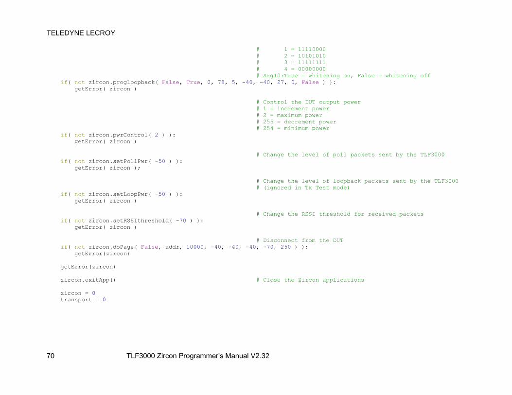
TELEDYNE LECROY
70 TLF3000 Zircon Programmer’s Manual V2.32
# 1 = 11110000
# 2 = 10101010
# 3 = 11111111
# 4 = 00000000
# Arg10:True = whitening on, False = whitening off
if( not zircon.progLoopback( False, True, 0, 78, 5, -40, -40, 27, 0, False ) ):
getError( zircon )
# Control the DUT output power
# 1 = increment power
# 2 = maximum power
# 255 = decrement power
# 254 = minimum power
if( not zircon.pwrControl( 2 ) ):
getError( zircon )
# Change the level of poll packets sent by the TLF3000
if( not zircon.setPollPwr( -50 ) ):
getError( zircon );
# Change the level of loopback packets sent by the TLF3000
# (ignored in Tx Test mode)
if( not zircon.setLoopPwr( -50 ) ):
getError( zircon )
# Change the RSSI threshold for received packets
if( not zircon.setRSSIthreshold( -70 ) ):
getError( zircon )
# Disconnect from the DUT
if( not zircon.doPage( False, addr, 10000, -40, -40, -40, -70, 250 ) ):
getError(zircon)
getError(zircon)
zircon.exitApp() # Close the Zircon applications
zircon = 0
transport = 0

5.2.5 Making measurements on a CW signal
The Zircon application can be made to measure the power and frequency of a CW signal. This can be
useful on a production line where a crystal must be trimmed prior to testing.
The sequence of operations is as follows:
1. A connection is made to the wanted TLF3000 unit using the connection code described in
Connecting to the TLF3000
2. The Zircon application is launched using the code described in Launching the Zircon application
3. A callback for asynchronous messages is registered using the code described in Handling
asynchronouos data
4. The operating mode is set to phy tester mode using setMode
5. The receiver port to be used is set using setRxPort
6. The receiver frontend attenuation is set using setRxAtten
7. The cable loss is set using setCableLoss
8. A call is made to measCW to make a measurement the frequency and power of the largest
signal found in the ISM band.
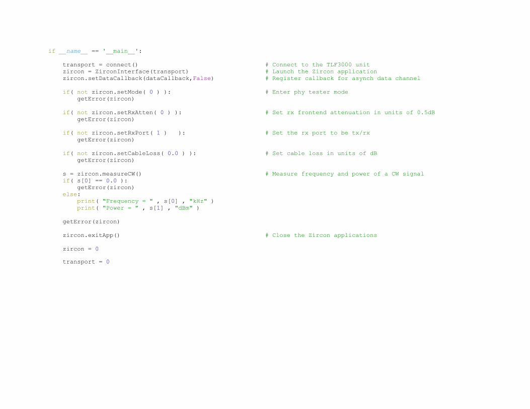
if __name__ == '__main__':
transport = connect() # Connect to the TLF3000 unit
zircon = ZirconInterface(transport) # Launch the Zircon application
zircon.setDataCallback(dataCallback,False) # Register callback for asynch data channel
if( not zircon.setMode( 0 ) ): # Enter phy tester mode
getError(zircon)
if( not zircon.setRxAtten( 0 ) ): # Set rx frontend attenuation in units of 0.5dB
getError(zircon)
if( not zircon.setRxPort( 1 ) ): # Set the rx port to be tx/rx
getError(zircon)
if( not zircon.setCableLoss( 0.0 ) ): # Set cable loss in units of dB
getError(zircon)
s = zircon.measureCW() # Measure frequency and power of a CW signal
if( s[0] == 0.0 ):
getError(zircon)
else:
print( "Frequency = " , s[0] , "kHz" )
print( "Power = " , s[1] , "dBm" )
getError(zircon)
zircon.exitApp() # Close the Zircon applications
zircon = 0
transport = 0
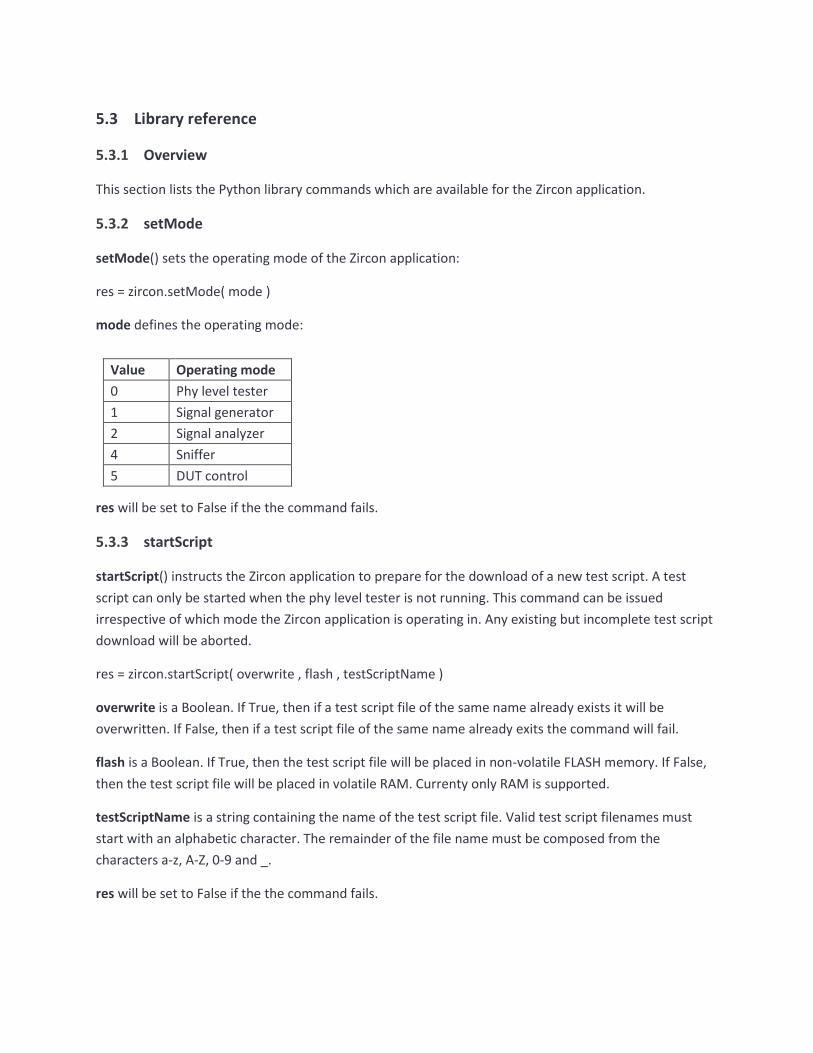
5.3 Library reference
5.3.1 Overview
This section lists the Python library commands which are available for the Zircon application.
5.3.2 setMode
setMode() sets the operating mode of the Zircon application:
res = zircon.setMode( mode )
mode defines the operating mode:
Value Operating mode
0 Phy level tester
1 Signal generator
2 Signal analyzer
4 Sniffer
5 DUT control
res will be set to False if the the command fails.
5.3.3 startScript
startScript() instructs the Zircon application to prepare for the download of a new test script. A test
script can only be started when the phy level tester is not running. This command can be issued
irrespective of which mode the Zircon application is operating in. Any existing but incomplete test script
download will be aborted.
res = zircon.startScript( overwrite , flash , testScriptName )
overwrite is a Boolean. If True, then if a test script file of the same name already exists it will be
overwritten. If False, then if a test script file of the same name already exits the command will fail.
flash is a Boolean. If True, then the test script file will be placed in non-volatile FLASH memory. If False,
then the test script file will be placed in volatile RAM. Currenty only RAM is supported.
testScriptName is a string containing the name of the test script file. Valid test script filenames must
start with an alphabetic character. The remainder of the file name must be composed from the
characters a-z, A-Z, 0-9 and _.
res will be set to False if the the command fails.

TELEDYNE LECROY
74 TLF3000 Zircon Programmer’s Manual V2.32
5.3.4 contScript
contScript() appends a new line to a test script previously opened using startScript but not yet closed
with an endScript. A test script can only be added to when the phy level tester is not running. This
command can be issued irrespective of which mode the Zircon application is operating in.
Each line in the test script is a sequence of ASCII characters defining a test to be performed and its
associated parameters. The test script is case insensitive. Full details of the test script format can be
found in Test Script Format.
res = zircon.contScript( line )
line is a character string containing the next line to be appended to the test script file. It is not necessary
to include an end of line character.
res will be set to False if the the command fails.
5.3.5 endScript
endScript() signifies that the entire content of a test script has been download. This can only be called
after startScript() has successfully be executed. This command cannot be executed if the phy level tester
is running. This command can be issued irrespective of which mode the Zircon application is operating
in.
res = zircon.endScript()
res will be set to False if the the command fails.
5.3.6 deleteScript
deleteScript() will delete a test script from the TLF3000 memory.
res = zircon.deleteScript( flash, testScriptName )
flash is a Boolean. If True, then the test script file to be deleted resides in non-volatile FLASH memory. If
False, then the test script file to be deleted resides in volatile RAM. Currenty only RAM is supported.
testScriptName is a string containing the name of the test script file to be deleted. Valid test script
filenames must start with an alphabetic character. The remainder of the file name must be composed
from the characters a-z, A-Z, 0-9 and _.
res will be set to False if the the command fails.

TELEDYNE LECROY
75 TLF3000 Zircon Programmer’s Manual V2.32
5.3.7 runScript
runScript() instructs the phy level tester to start executing a test script. This command can only be
executed when the Zircon application is in phy level test mode. It cannot be executed whilst a test script
is being downloaded, i.e. after a startScript() command and prior to an endScript() command.
res = zircon.startScript( addr, timeoout, pagePwr , pollPwr , tstPwr , rssi, supervision, repeat ,
runToCompletion , onlyLimts , flash , testScriptName )
addr specifies the Bluetooth address of the DUT to be tested.
pagePwr specifies the power at which the Zircon application will transmit packets during paging. During
paging Zircon transmits on all paging channels simultaneously. If the device has its page scan activity set
so that it listens frequently, then it will connect almost instaneoulsy, thereby dramatically reducing test
time. As a consequence of transmitting on all paging channels simultaneously, the maximum power per
channel is limited to around -30dBm. Units of pagePwr are dBm/channel.
pollPwr specifies the power at which the Zircon application will transmit poll packets and LMP packets.
Units of pollPwr are dBm.
tstPwr specifies the power at which the Zircon application will transmit packets when in the loopback
test mode. Units of tstPwr are dBm.
rssi is a threshold for received packets. Only those packets which are above the RSSI threshold will be
analysed. Units of rssi are dBm.
supervision specifies the supervision timeout for the link. Units are in ms.
repeat specifies the number of times the testScript will be executed.
runToCompletion is a Boolean. If set, then all the tests specified in the test script will be performed. If
not set, then the test script will terminate as soon as a test failure is detected.
onlyLimits is a Boolean. If set, the receiver tests will terminate as soon as sufficient packets have been
sent to determine whether the test will pass or fail the BER limit. This will reduce the accuracy of the
returned BER value but will dramatically reduce test time.
flash is a Boolean. If True, then the test script file to be run resides in non-volatile FLASH memory. If
False, then the test script file to be run resides in volatile RAM. Currenty only RAM is supported.
testScriptName is a string containing the name of the test script file to be run. Valid test script filenames
must start with an alphabetic character. The remainder of the file name must be composed from the
characters a-z, A-Z, 0-9 and _.
res will be set to False if the the command fails.

TELEDYNE LECROY
76 TLF3000 Zircon Programmer’s Manual V2.32
5.3.8 abortScript
abortScript() instructs the phy level tester to abort an executing a test script. This command can only be
executed when the Zircon application is in phy level test mode and a test script is running.
res = zircon.abortScript()
res will be set to False if the the command fails.
5.3.9 setCableLoss
setCableLoss() informs the Zircon application of the cable loss between the Tx/Rx port of the TLF3000
unit and the DUT. The loss is specified at 2.4 GHz. The Zircon application requires knowledge of this loss
to compensate its transmit power and to calibrate its received signal strength measurements. The same
loss is also used to compensate the out-of-band CW blocker. Since the cable loss will vary between 24
MHz and 6 GHz, this compensation can only be approximate.
res = zircon.setCableLoss( dB )
dB is the cable loss in dB. The cable loss must be between 0 and 25dB.
res will be set to False if the the command fails.
5.3.10 setCableLosses
setCableLosses() informs the Zircon application of the cable loss between the Tx/Rx port of the TLF3000
unit and the DUT as a function of frequency within the 2.4GHz band. The Zircon application requires
knowledge of this loss to compensate its transmit power and to calibrate its received signal strength
measurements. The same loss is also used to compensate the out-of-band CW blocker. Since the cable
will vary between 24 MHz and 6 GHz, this compensation can only be approximate.
res = zircon.setCableLosses( n, frqs, dBs )
n is the number of frqs,dBs pairs. Each pair defines the cable loss at one frequency.
frqs is a vector_float which must be imported from Frontline. It consists of a list of frequencies in MHz at
which the cable loss is specified. All frequencies must lie within the 2.4GHz band and be monotonic.
dBs is a vector_float which must be imported from Frontline. It consists of a list of cable losses in dB,
each entry corresponding to the frequency specified in frqs. The cable loss must be between 0 and
25dB.
res will be set to False if the the command fails.

TELEDYNE LECROY
77 TLF3000 Zircon Programmer’s Manual V2.32
5.3.11 progWanted
progWanted() programs the wanted signal when the Zircon application is in signal generator mode. This
command can only be executed when the Zircon application is in signal generator mode. There will be
no output from the signal generator until startSigGen is invoked.
res = zircon.progWanted( on , chan , pwr , phy , uap, whiten, clk, lap, hdr, payHdr, pktTyp, payload,
guard, rel, numPkt, pktInt, ramp, before, after, octets, distortions )
on is a Boolean to indicate whether the wanted signal should be enabled. If this flag set, then the
wanted signal will be enabled, otherwise the wanted signal is disabled.
chan is the RF channel number for the wanted signal. Valid channels are in the range 0 to 79.
pwr is the power of the wanted signal in units of dBm. This should be in range -120dBm to 0dBm for BR
packets and -120dBm to -3.1dBm for EDR packets.
phy is the phy to be used by the wanted signal. Valid options are:
0 Basic rate
1 2-EDR
2 3-EDR
uap is the UAP of the Bluetooth address. This is required to generate the HEC for the header.
whiten is a Boolean. If True the packet will be whitened. If False, the packet will not be whitened.
clk is the current value of the central clock. The LSBs are used for whitening the packet. If whitening is
not enabled, then this parameter is ignored.
lap is the 24bit LAP of the Bluetooth address.
hdr is the 10bits of the header without the HEC. The header bits denoting the packet type are ignored
and are set on the basis of the parameter pktTyp.
payHdr is the appropriate payload header for the selected packet type. The length field in the payload
header is ignored and filled using the contents of the parameter octets.

TELEDYNE LECROY
78 TLF3000 Zircon Programmer’s Manual V2.32
pktTyp is the type of packet to be transmitted:
0 ID
1 Null
2 Poll
3 FHS
4 DM1
5 DH1
6 DM3
7 DH3
8 DM5
9 DH5
10 AUX1
11 2-DH1
12 2-DH3
13 2-DH5
14 3-DH1
15 3-DH3
16 3-DH5
17 HV1
18 HV2
19 HV3
20 DV
21 EV3
22 EV4
23 EV5
24 2-EV3
25 2-EV5
26 3-EV3
27 3-EV5

TELEDYNE LECROY
79 TLF3000 Zircon Programmer’s Manual V2.32
payload defines the contents of the wanted signal’s payload. Valid options are:
0 PRBS9
1 PRBS11
2 PRBS15
3 PRBS20
4 PRBS23
5 PRBS29
6 PRBS31
7 11110000 in transmission order
8 10101010 in transmission order
9 11111111
10 00000000
11 00001111 in transmission order
12 01010101 in transmission order
guard is the adjustment to the guard interval in µs. This parameter is ignored for BR packets.
rel is the amplitude of the EDR portion of the packet relative to the GFSK portion of the packet in dB.
numPkt is the number of packets to be transmitted. If this parameter is set to zero, then packets will be
transmitted indefinitely.
ramp is the time of the power ramp up and down in units of µs.
before is the length of unmodulated carrier after the power ramp and before the first symbol of the
preamble in units of µs.
after is the length of unmodulated carrier after the last symbol of the payload/CRC and the start of the
power ramp down in units of µs.
octets is the number of octets in the payload, excluding payload header and CRC.
distortions is a vector__int16 which must be imported from the zircon module. See example signal
generator code. Its contents are groups of 5 int16 which described the distortions to be applied:
0 Carrier offset kHz
1 Modulation index X 10000
2 Drift magnitude kHz
3 Drift rate kHz
4 Symbol timing error ppm
For basic rate packets, each group of distortions is repeated for 20ms before moving onto the next
group of distortions in the table. Once the table has been exhausted, it is restarted from the top. For
EDR packets each group of distortions is repeated 20 times. The sign of the carrier drift is automatically
reversed by the Zircon application on alternate packets.
TELEDYNE LECROY
80 TLF3000 Zircon Programmer’s Manual V2.32
res will be set to False if the the command fails.
5.3.12 progInterferer
progInterferer() programs the modulated interferer signal generator when the Zircon application is in
signal generator mode. This command can only be executed when the Zircon application is in signal
generator mode. There will be no output from the signal generator until startSigGen is invoked. The
interferer is modulated by a PRBS15 sequence.
res = zircon.setInterferer( on , cont , pwr , phy , octets , freq , pktInt )
on is a Boolean to indicate whether the modulated interferer signal generator should be enabled. If this
flag is set, then the modulated interferer signal generator is enabled, otherwise the modulated
interferer signal generator is disabled.
cont indicates whether the inteferer is a continuous transmission or packetised. If this parameter is
True, then the interferer is a continuous transmission. If this parameter is False then the interferer is a
packetised transmiision,
pwr is the power of the modulated interferer signal in dBm. Valid range is -120dBm to 0dBm for a basic
rate interferer and -120dBm to -3.1dBm for an EDR interferer.
phy is the phy to be used by the modulated interferer signal. Valid options are:
0 Basic rate
1 2-EDR
2 3-EDR
octets determines the number of octets in the packet payload for packetised transmissions. This
parameter is ignored it cont is True.
freq is the transmission frequency of the interferer in units of MHz.
pktInt is the interval between the start of one packet of the interferer and the start of the subsequent
packet in units of µs. This parameter is ignored if cont is True.
res will be set to False if the the command fails.
5.3.13 progCW
progCW() programs the in-band CW signal generator when the Zircon application is in signal generator
mode. This command can only be executed when the Zircon application is in signal generator mode.
There will be no output from the signal generator until startSigGen is invoked.
res = zircon.progCW( num , on , pwr , freq )
TELEDYNE LECROY
81 TLF3000 Zircon Programmer’s Manual V2.32
num indicates which of the two in-band CW sources is being programmed. Valid values are 0 and 1.
on is a Boolean to indicate whether the in-band CW generator should be enabled. If set, then the in-
band CW generator is enabled, otherwise the in-band CW generator is disabled.
pwr is the power of the in-band CW signal in units of dBm. Valid range is -120 dBm to 0 dBm.
freq is the frequency of the in-band CW signal in Hz. Valid range is 2,395,000,000 Hz to 2,485,000,000 Hz
inclusive.
res will be set to False if the the command fails.
5.3.14 progAWGN
progAWGN programs the AWGN generator when the Zircon application is in signal generator mode. This
command can only be executed when the Zircon application is in signal generator mode. There will be
no output from the signal generator until startSigGen is invoked.
res = zircon.progAWGN( on , pwr )
on is a Boolean to indicate whether the AWGN generator should be enabled. If set, then the AWGN
generator is enabled, otherwise the AWGN generator is disabled.
pwr is the power of the AWGN signal in units of dBm/MHz. Valid range is -162 dBm/MHz to -42
dBm/MHz.
res will be set to False if the the command fails.
5.3.15 progOutOfBandCW
progOutOfBandCW programs the out-of-band CW signal generator when the Zircon application is in
signal generator mode. This command can only be executed when the Zircon application is in signal
generator mode. There will be no output from the signal generator until startSigGen is invoked.
res = zircon.progOutOfBandCW( on , pwr , freq )
on is a Boolean to indicate whether the out-of-band CW generator should be enabled. If set, then the
out-of-band CW generator is enabled, otherwise the out-of-band CW generator is disabled.
pwr is the power of the out-of-band CW signal in units of dBm. Valid range is -50dBm to -28 dBm.
freq is the frequency of the out-of-band CW signal in MHz. Valid range is 24 MHz to 6,000 MHz.
res will be set to False if the the command fails.
TELEDYNE LECROY
82 TLF3000 Zircon Programmer’s Manual V2.32
5.3.16 startSigGen
startSSigGen determines when the signal generator is active. This is a global enable for the signal
generator output; it overrides the individual on fields for the wanted signal, modulated interferer, in-
band CW, AWGN and out-of-band CW. This command can only be executed when the Zircon application
is in signal generator mode.
res = zircon.startSigGen()
res will be set to False if the the command fails.
5.3.17 stopSigGen
stopSigGen will stop all output from the signal generator. It will not affect the programming of the
various signal sources, ie the wanted signal, modulated interferer, in-band CW, AWGN and out-of-band
CW. This command can only be executed when the Zircon application is in signal generator mode.
res = zircon.stopSigGen( )
res will be set to False if the the command fails.
5.3.18 startSigAna
startSigAna() starts the signal analyser. This command can only be executed when the Zircon application
is in signal analyser mode.
res = zircon.startStopSigAna( supervision , RSSIthresh )
supervision is the supervision timeout for the link in ms. This parameter is ignored if the Zircon
application is not currently controlling a DUT.
RSSIthresh Only packets with an RSSI greater than RSSIthresh will be analysed. RSSIthresh is in units of
dBm.
res will be set to False if the the command fails.
5.3.19 stopSigAna
stopSigAna() will stop the signal analyser running. This command can only be executed when the Zircon
application is in signal analyser mode.
res = zircon.stopSigAna()
res will be set to False if the the command fails.

TELEDYNE LECROY
83 TLF3000 Zircon Programmer’s Manual V2.32
5.3.20 pollSigAnaTable
pollSigAnaTable() returns results in a tabular form when operating in signal analyser mode.
The results contributing to the returned table are filtered by:
1. An RF channel filter
2. A phy filter
3. A packet slot filter
If the phy filter contains basic rate packets, then only results for basic rate packets will be returned. If
the phy filter does not contain basic rate packets, then only results for EDR packets will be returned. All
packets which satisfy the RF channel and packet slot filter will contribute to the statistics returned in the
table.
table = zircon.pollSigAnaTable( meas , chanMask , phyMask , slotMask )
meas is the measurement set for which tabular results are requested. Possible values are:
Meas Measurement set
0x00000000 Output power
0x00000001 Modulation characteristics
0x00000002 Carrier offset & drift
0x00000003 Spectrum
0x00000004 BER
chanMask is a vector_uchar containing a 79 bit mask indicating containing the RF channel filter.
vector_uchar must be imported from Frontline. Only packets which pass the RF channel filter will
contribute to the statistics in the returned table. A ‘1’ in the mask indicates that the corresponding RF
channel results should be included in the table, a ‘0’ in the mask indicates that the corresponding RF
channel results should be ignored.
phyMask is a 3 bit mask containing the phy filter. If basic rate is selected in the mask, then only results
for basic rate packets will be returned. If basic rate is not set, then combined results for the remaining
selected phys will be returned.
Bit Position Bit Mask Phy
0 0x01 Basic rate
1 0x02 2-EDR
2 0x04 3-EDR
slotMask. this mask contains the packet slot filter. Only packets which pass the packet slot filter will
contribute to the statistics in the returned table. If a bit is ‘1’, then the results for the corresponding

TELEDYNE LECROY
84 TLF3000 Zircon Programmer’s Manual V2.32
packet slot will contribute to the statistics in the returned table. If a bit is ‘0’, then the results for the
corresponding slot are ignored.
Bit Position Bit Mask Packet slots
0 0x01 1 slot packets
1 0x02 3 slot packets
2 0x04 5 slot packets
table is a vector_float type which must be imported from Frontline. See example signal analyser code. It
contains the requested table of results. The first 5 values in table correspond to the first row in the
table, the second 5 values to the second row, etc. The tables returned for the various measurement sets
are:
1. Basic rate output power
Quantity Packet Count Minimum Maximum Average Current
Pavg
Pk - Pavg
EDR output power
Quantity Packet Count Minimum Maximum Average Current
Pavg
PGFSK - PDPSK
Guard- 99%
Guard+ 99%
Guard > 4.6µs
Guard < 5.4µs
2. Basic rate modulation characteristics
Quantity Packet Count Minimum Maximum Average Current
ΔF1max
ΔF1avg
ΔF2max
ΔF2avg
ΔF2avg / ΔF1avg
ΔF2max 99.9%
ΔF2max > 99%

TELEDYNE LECROY
85 TLF3000 Zircon Programmer’s Manual V2.32
EDR modulation characteristics
Quantity Packet Count Minimum Maximum Average Current
RMS DEVM
Peak DEVM
DEVM ≤ 30%
DEVM @ 99%
3. Basic rate carrier offset and drift
Quantity Packet Count Minimum Maximum Average Current
F0
Fk+5 - Fk
1 slot F0 - Fk
3 slot F0 - Fk
5 slot F0 - Fk
EDR rate carrier offset and drift
Quantity Packet Count Minimum Maximum Average Current
ωi
ω0
ωi + ω0
4. Basic rate spectrum
Quantity Packet Count Minimum Maximum Average Current
Fl
Fh
ΔF
Ftx ± 2MHz
Ftx ± (3+n)MHz
# Exceptions
Max exception
Power density
TELEDYNE LECROY
86 TLF3000 Zircon Programmer’s Manual V2.32
EDR spectrum
Quantity Packet Count Minimum Maximum Average Current
Fl
Fh
ΔF
Ptx26 - Ptxref
Ftx ± 2MHz
Ftx ± (3+n)MHz
# Exceptions
Max exception
Power density
5. BER
Quantity Packet Count Minimum Maximum Average Current
Log10(BER)
Packet loss rate
5.3.21 pollResultsPlot
polltResultsPlot() instructs Zircon to capture data ready for reading back in a subsequent command,
n = zircon.pollResultsPlot( quantity , method , phyMask , slotMask , chanMask )
To access plot data, a sequence of two commands is required:
1. pollPlotResults. This command determines whether data is available, and if so, stashes it within
the Zircon application.
2. getPlotResultsFloat. This command reads back sections of the stashed data.
Multiple getPlotResultsFloat commands can be issued to retrieve different sections of the stashed data.
The pollResultsPlot command has 5 arguments:

TELEDYNE LECROY
87 TLF3000 Zircon Programmer’s Manual V2.32
Quantity. The measured quantity for which the plot is requested. Possible values are:
Quantity Measurement Phy
0 Pavg Basic rate
1 Pk - Pavg Basic rate
100 ΔF1max Basic rate
101 ΔF1avg Basic rate
102 ΔF2max Basic rate
103 ΔF2avg Basic rate
104 ΔF2avg /ΔF1avg Basic rate
105 ΔF2max 99% percentile Basic rate
106 ΔF2max ≥ 115kHz Basic rate
200 F0 Basic rate
201 Fk+5 - Fk Basic rate
202 F0 – Fk 1 slot packets Basic rate
203 F0 – Fk 3 slot packets Basic rate
204 F0 – Fk 5 slot packets Basic rate
205 F0 – Fk any slots Basic rate
300 Fl Basic rate
301 Fh Basic rate
302 ΔF Basic rate
303 Ftx ± 2MHz Basic rate
304 Ftx ± (3+n)MHz Basic rate
305 # Exceptions Basic rate
306 Max exception Basic rate
307 Power density Basic rate
400 BER Basic rate
401 PER Basic rate
1000 Pavg 2-EDR
1001 PGFSK - PDPSK 2-EDR
1002 Guard- 99% 2-EDR
1003 Guard+ 99% 2-EDR
1004 Guard > 4.6µs 2-EDR
1005 Guard < 5.4µs 2-EDR
1050 Guard 2-EDR
1100 RMS DEVM 2-EDR
1101 Peak DEVM 2-EDR
1102 DEVM ≤ 30% 2-EDR
1103 DEVM @ 99% 2-EDR
1150 DEVM 2-EDR

TELEDYNE LECROY
88 TLF3000 Zircon Programmer’s Manual V2.32
1200 ωi 2-EDR
1201 ω0 2-EDR
1202 ωi + ω0 2-EDR
1300 Fl 2-EDR
1301 Fh 2-EDR
1302 ΔF 2-EDR
1303 Ptx26 - Ptxref 2-EDR
1304 Ftx ± 2MHz 2-EDR
1305 Ftx ± (3+n)MHz 2-EDR
1306 # Exceptions 2-EDR
1307 Max exception 2-EDR
1308 Power density 2-EDR
1400 BER 2-EDR
1401 PER 2-EDR
2000 Pavg 3-EDR
2001 PGFSK - PDPSK 3-EDR
2002 Guard- 99% 3-EDR
2003 Guard+ 99% 3-EDR
2004 Guard > 4.6µs 3-EDR
2005 Guard < 5.4µs 3-EDR
2050 Guard 3-EDR
2100 RMS DEVM 3-EDR
2101 Peak DEVM 3-EDR
2102 DEVM ≤ 30% 3-EDR
2103 DEVM @ 99% 3-EDR
2150 DEVM 3-EDR
2200 ωi 3-EDR
2201 ω0 3-EDR
2202 ωi + ω0 3-EDR
2300 Fl 3-EDR
2301 Fh 3-EDR
2302 ΔF 3-EDR
2303 Ptx26 - Ptxref 3-EDR
2304 Ftx ± 2MHz 3-EDR
2305 Ftx ± (3+n)MHz 3-EDR
2306 # Exceptions 3-EDR
2307 Max exception 3-EDR
2308 Power density 3-EDR
2400 BER 3-EDR
2401 PER 3-EDR

TELEDYNE LECROY
89 TLF3000 Zircon Programmer’s Manual V2.32
3000 Amplitude waveform Last packet
3001 FM demodulated waveform Last packet
3002 IQ data Last packet
3003 Frequency range spectrum Last packet
3004 20dB bandwidth spectrum Last packet
3005 ACP spectra Last packet
3006 Power density spectrum Last packet
Method. Describes the type of plot which is requested. Possible values are:
0x00000000 Quantity vs RF channel
0x00000001 Quantity vs packet slots
0x00000002 Quantity vs phy
0x00000003 Histogram of quantity
Otherwise vs time or frequency
phyMask is a 3 bit mask containing the phy filter. If basic rate is selected in the mask, then only results
for basic rate packets will be returned. If basic rate is not set, then combined results for the remaining
selected phys will be returned.
Bit Position Bit Mask Phy
0 0x01 Basic rate
1 0x02 2-EDR
2 0x04 3-EDR
slotMask. this mask contains the packet slot filter. Only packets which pass the packet slot filter will
contribute to the statistics in the returned table. If a bit is ‘1’, then the results for the corresponding
packet slot will contribute to the statistics in the returned table. If a bit is ‘0’, then the results for the
corresponding slot are ignored.
Bit Position Bit Mask Packet slots
0 0x01 1 slot packets
1 0x02 3 slot packets
2 0x04 5 slot packets
chanMask is a vector_uchar containing a 79 bit mask indicating containing the RF channel filter.
vector_uchar must be imported from Frontline. Only packets which pass the RF channel filter will
contribute to the statistics in the returned table. A ‘1’ in the mask indicates that the corresponding RF
channel results should be included in the table, a ‘0’ in the mask indicates that the corresponding RF
channel results should be ignored.

TELEDYNE LECROY
90 TLF3000 Zircon Programmer’s Manual V2.32
Returns n the number of samples which are available for reading back.
The number of samples available to be read back is:
Method Number of returned samples Bytes available to read
0 3*79 = 237 948
1 3*3 = 9 36
2 3*3 = 9 36
3 128 512
For Method = 0, the first 79 samples correspond to the minimum value observed over RF channels 0 to
78. The next 79 samples correspond to the average value observed over RF channels 0 to 78. The final
79 samples correspond to the maximum value observed over RF channels 0 to 78.
For Method = 1, the first 3 samples correspond to the minimum value observed for each modulation
scheme. The order of the modulation schemes is:
1. Basic rate
2. 2-EDR
3. 3-EDR
The next 3 samples correspond the average value observed for each modulation scheme. The final 3
samples correspond to the maximum value observed for each modulation scheme.
For Method = 2, the first 3 samples correspond the minimum value observed for each of the packet slot
lengths. The next 3 samples correspond the average value observed for each of the packet slot lengths.
The final 3 samples correspond to the maximum value observed for each of the packet slot lengths. The
order of the packet slot lengths is:
1. 1 slot packets
2. 3 slot packets
3. 5 slot packets
The units of the returned quantities are:

TELEDYNE LECROY
91 TLF3000 Zircon Programmer’s Manual V2.32
Measurement Units
Pavg dBm
Pk - Pavg dB
ΔF1max kHz
ΔF1avg kHz
ΔF2max kHz
ΔF2avg kHz
ΔF2avg /ΔF1avg Dimensionless
ΔF2max 99% percentile kHz
ΔF2max ≥ 115kHz kHz
F0 kHz
Fk+5 - Fk kHz
F0 – Fk 1 slot packets kHz
F0 – Fk 3 slot packets kHz
F0 – Fk 5 slot packets dBm
F0 – Fk any slots dBm
Fl Dimensionless
Fh dBm
ΔF dBm
Ftx ± 2MHz dBm
Ftx ± (3+n)MHz kHz
# Exceptions kHz
Max exception kHz
Power density kHz
PGFSK - PDPSK dB
Guard- 99% µs
Guard+ 99% µs
Guard > 4.6µs %
Guard < 5.4µs %
Guard µs
RMS DEVM %
Peak DEVM %
DEVM ≤ 30% %
DEVM @ 99% %
DEVM %
ωi kHz
ω0 kHz
ωi + ω0 kHz
Ptx26 - Ptxref dB
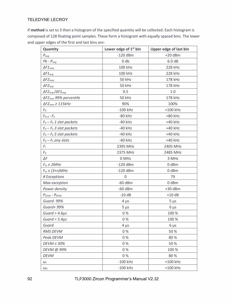
TELEDYNE LECROY
92 TLF3000 Zircon Programmer’s Manual V2.32
If method is set to 3 then a histogram of the specified quantity will be collected. Each histogram is
composed of 128 floating point samples. These form a histogram with equally spaced bins. The lower
and upper edges of the first and last bins are:
Quantity Lower edge of 1st bin Upper edge of last bin
Pavg -120 dBm +20 dBm
Pk - Pavg 0 db 6.0 dB
ΔF1max 100 kHz 228 kHz
ΔF1avg 100 kHz 228 kHz
ΔF2max 50 kHz 178 kHz
ΔF2avg 50 kHz 178 kHz
ΔF2avg /ΔF1avg 0.5 1.0
ΔF2max 99% percentile 50 kHz 178 kHz
ΔF2max ≥ 115kHz 90% 100%
F0 -100 kHz +100 kHz
Fk+5 - Fk -80 kHz +80 kHz
F0 – Fk 1 slot packets -40 kHz +40 kHz
F0 – Fk 3 slot packets -40 kHz +40 kHz
F0 – Fk 5 slot packets -40 kHz +40 kHz
F0 – Fk any slots -40 kHz +40 kHz
Fl 2395 MHz 2405 MHz
Fh 2375 MHz 2485 MHz
ΔF 0 MHz 3 MHz
Ftx ± 2MHz -120 dBm 0 dBm
Ftx ± (3+n)MHz -120 dBm 0 dBm
# Exceptions 0 79
Max exception -60 dBm 0 dBm
Power density -60 dBm +30 dBm
PGFSK - PDPSK -10 dB +10 dB
Guard- 99% 4 µs 5 µs
Guard+ 99% 5 µs 6 µs
Guard > 4.6µs 0 % 100 %
Guard < 5.4µs 0 % 100 %
Guard 4 µs 6 µs
RMS DEVM 0 % 50 %
Peak DEVM 0 % 80 %
DEVM ≤ 30% 0 % 50 %
DEVM @ 99% 0 % 100 %
DEVM 0 % 80 %
ωi -100 kHz +100 kHz
ω0 -100 kHz +100 kHz

TELEDYNE LECROY
93 TLF3000 Zircon Programmer’s Manual V2.32
ωi + ω0 -100 kHz +100 kHz
Ptx26 - Ptxref -60 dB 0 dB
If method is set to 4, then the specified quantity is collected as a function of time or frequency.
For those quantities which are collected as a function of time, the saved data consists of 28 bytes of
meta data followed by the requested quantity as a series of floating point numbers. The meta data is
composed of 7 uint32_t:
1. uint32_t : MSB. MSB of timestamp of packet P0 location in units of 250 ns since the Unix epoch
of 1970-01-01 00:00:00 + 0000 (UTC).
2. uint32_t : LSB. LSB of timestamp of packet P0 location in units of 250 ns since the Unix epoch of
1970-01-01 00:00:00 + 0000 (UTC).
3. uint32_t : N. The number of samples available.
4. uint32_t : RF Chan. The RF channel number on which the packet was collected.
5. uint32_t : Slots. Indicates the number of slots in the packet. Possible values are:
0 1 slot packet
1 3 slot packet
2 5 slot packet
6. uint32_t : Phy. phy of the packet for which the data was collected. Possible values are:
0 Basic rate
1 2-EDR
2 3-EDR
7. uint32_t : Bits. The number of bits in the packet payload.
The units of the returned quantities are the same as for methods 1, 2 and 3.
For basic rate packets:
1. The first samples of ΔF1max and ΔF2max correspond to bit 4 of the payload. The interval between
samples is 1 bit. Samples which are not valid contain NaN.
2. The first samples of Fn correspond to the average starting at bit 1 of the payload. The interval
between samples is 10 bits. These samples are used to derive F0 - Fn and Fn+5 – Fn.
Amplitude, FM deviation and IQ data commence 15µs prior to the starts of the packet and continue for
15µs past the end of the packet.
For ACP spectra the data which can be read back represents in-band emissions as a function of
frequency. Results are available for both the final 1MHz resolution spectrum and the 100kHz resolution
spectrum which was summed to generate the 1MHz spectrum. This provides greater visibility of what is
dominating the in-band emissions.

TELEDYNE LECROY
94 TLF3000 Zircon Programmer’s Manual V2.32
The available data can contain the following fields:
1. 91*float : Curr_1MHz. The last recorded value of the in-band emissions as a function of
frequency from 2395MHz to 2485 MHz.
2. 910*float : Curr_100kHz. The last recorded values of the 100 kHz spectrum summed to generate
the in-band emissions spectrum as a function of frequency from 24394.550 MHz to 2485.450
MHz.
For frequency range or power density spectra, data which can be read back are 100kHz resolution
spectra spanning from 2395MHz to 2485MHz. There are 901 float available for reading back.
For 20dB bandwidth spectra, data which can be read back consist of 81*200 float. These cover
2400.5MHz to 2481.5MHz in steps of 5kHz. Only those 600 points centred on the channel of the last
packet which satisfied the filters will be populated.
All spectra are in units of dBm.
n is the number of bytes of data which are available to be read back, or zero if no data is available.
5.3.22 getResultsPlotFloat
getResultsPlotFloat() reads back the data which was captured using a previous polltResultsPlot()
command. This command should be used when the captured data consisted of an array of float.
x = zircon.getResultsPlotFloat( offset , count )
offset is the offset from the start of the buffer of the data to be read back (see pollResultsPlot). The
offset is in units of 4 bytes.
count is the number of float to be read back from the buffer.
x is the data read back from the buffer. x is a vector_float which must be imported from the Zircon
module.
5.3.23 clearResults
clearResults() erases all test results accumulated in the Zircon application by the signal analyser mode or
the phy tester mode. This command can be executed at any time.
res = zircon.clearResults()
res will be set to False if the the command fails.
5.3.24 setLimits
setLimits() informs the Zircon application of the test limits to be applied. The test limits are used in phy
tester mode and signal analyser mode. This command can be executed at any time.

TELEDYNE LECROY
95 TLF3000 Zircon Programmer’s Manual V2.32
res = zircon.setLimits( x )
x is a vector_int16 containing the test limits. vector_int16 must be imported from the Zircon module
(see example signal analyser code).
Limit Test Quantity Phy Limit type Units
1 Ouput power Pavg BR Lower 0.1 dBm
2 Ouput power Pavg BR Upper 0.1 dBm
3 Modulation characteristics ΔF1avg BR Lower 100 Hz
4 Modulation characteristics ΔF1avg BR Upper 100 Hz
5 Modulation characteristics ΔF2avg /ΔF1avg BR Lower 0.001
6 Modulation characteristics ΔF2 99.9% percentile BR - 100 Hz
7 Modulation characteristics ΔF2 ≤ 115 kHz BR 0.01%
8 Carrier frequency & drift F0 BR Lower 100 Hz
9 Carrier frequency & drift F0 BR Upper 100 Hz
10 Carrier frequency & drift Fk+5 – Fk BR Lower 100 Hz
11 Carrier frequency & drift Fk+5 – Fk BR Upper 100 Hz
12 Carrier frequency & drift F0 – Fk 1 slot packets BR Lower 100 Hz
13 Carrier frequency & drift F0 – Fk 1 slot packets BR Upper 100 Hz
14 Carrier frequency & drift F0 – Fk 3 slot packets BR Lower 100 Hz
15 Carrier frequency & drift F0 – Fk 3 slot packets BR Upper 100 Hz
16 Carrier frequency & drift F0 – Fk 5 slot packets BR Lower 100 Hz
17 Carrier frequency & drift F0 – Fk 5 slot packets BR Upper 100 Hz
18 Ouput power Pavg 2-EDR Lower 0.1 dBm
19 Ouput power Pavg 2-EDR Upper 0.1 dBm
20 Modulation characteristics PGFSK - PDPSK 2-EDR Lower 0.1 dB
21 Modulation characteristics PGFSK - PDPSK 2-EDR Upper 0.1 dB
22 Modulation characteristics Guard- 99% 2-EDR - ns
23 Modulation characteristics Guard+ 99% 2-EDR - ns
24 Modulation characteristics Guard > 4.6µs 2-EDR - 0.01 %
25 Modulation characteristics Guard < 5.4µs 2-EDR - 0.01 %
26 Modulation characteristics RMS DEVM 2-EDR Upper 0.01 %
27 Modulation characteristics Peak DEVM 2-EDR Upper 0.01 %
28 Modulation characteristics DEVM 99% percentile 2-EDR - 0.01 %
29 Modulation characteristics DEVM ≤ 30% 2-EDR - 0.01 %
30 Carrier frequency & drift ωi 2-EDR Lower 100 Hz
31 Carrier frequency & drift ωi 2-EDR Upper 100 Hz
32 Carrier frequency & drift ω0 2-EDR Lower 100 Hz
33 Carrier frequency & drift ω0 2-EDR Upper 100 Hz
34 Carrier frequency & drift ωi + ω0 2-EDR Lower 100 Hz

TELEDYNE LECROY
96 TLF3000 Zircon Programmer’s Manual V2.32
35 Carrier frequency & drift ωi + ω0 2-EDR Upper 100 Hz
36 Ouput power Pavg 3-EDR Lower 0.1 dBm
37 Ouput power Pavg 3-EDR Upper 0.1 dBm
38 Modulation characteristics PGFSK - PDPSK 3-EDR Lower 0.1 dB
39 Modulation characteristics PGFSK - PDPSK 3-EDR Upper 0.1 dB
40 Modulation characteristics Guard- 99% 3-EDR - ns
41 Modulation characteristics Guard+ 99% 3-EDR - ns
42 Modulation characteristics Guard > 4.6µs 3-EDR - 0.01 %
43 Modulation characteristics Guard < 5.4µs 3-EDR - 0.01 %
44 Modulation characteristics RMS DEVM 3-EDR Upper 0.01 %
45 Modulation characteristics Peak DEVM 3-EDR Upper 0.01 %
46 Modulation characteristics DEVM 99% percentile 3-EDR - 0.01 %
47 Modulation characteristics DEVM ≤ 30% 3-EDR - 0.01 %
48 Carrier frequency & drift ωi 2-EDR Lower 100 Hz
49 Carrier frequency & drift ωi 2-EDR Upper 100 Hz
50 Carrier frequency & drift ω0 2-EDR Lower 100 Hz
51 Carrier frequency & drift ω0 2-EDR Upper 100 Hz
52 Carrier frequency & drift ωi + ω0 2-EDR Lower 100 Hz
53 Carrier frequency & drift ωi + ω0 2-EDR Upper 100 Hz
res will be set to False if the the command fails.
5.3.25 doInquiry
doInquiry() instructs the Zircon application to perform an inquiry to discover devices. For every DUT
discovered a callback will be executed (see Controlling a DUT over-the-air) from which the address and
RSSI of the DUT can be extracted. A further callback will be executed when the inquiry terminates.
res = zircon.doInquiry( run, duration, pwr, rssi, nresp )
run is a Boolean. If run is True, then an inquiry will be started. If run is False, then any existing inquiry
will be terminated.
duration is the maximum time for the inquiry in ms. Once this time has expired the inquiry will
terminate.
pwr is the power for the inquiry packets in dBm. The Zircon application transmits on all inquiry channels
simultaneously. If the inquiry scan activity of the DUT is set to ensure the DUT listens frequently, then
the DUT will be discovered almost instantaneously. Because the Zircon application is transmitting on all
inquiry channels simultaneously, the maximum power per channel is limited to -30dBm.
rssi is an RSSI threshold. Packets which are below the RSSI threshold will be ignored. This can be used to
ensure that only nearby devices are found. Units are in dBm.

TELEDYNE LECROY
97 TLF3000 Zircon Programmer’s Manual V2.32
nresp is the maximum number of inquiry responses required. Once nresp devices have been found the
inquiry will be terminated. Hence if there is only one device that needs to be found the inquiry can be
terminated as soon as that device is located. If nresp is set to zero, then there is no limit on the number
of inquiry responses.
res will be set to False is the command fails.
5.3.26 doPage
doPage() instructs the Zircon application to connect to a device and attempt to place it into test mode. It
can also be used to terminate a connection. A callback is executed whenever a connection is terminated.
See Controlling a DUT over-the-air.
res = zircon.doPage( run, addr, timeout, pagePwr, pollPwr, tstPwr, rssi, supervision )
run is a Boolean. If run is True, then an attempt will be made to connect to the device and place it into
test mode. If run is False, then any existing connection to a device will be terminated.
addr is the Bluetooth address of the device to connect to. Only the LAP Is required. This argument is
ignored if run is False.
timeout a timeout for establishing the connection. Units are ms.
pagePwr is the power in dBm of the ID packets transmitted by the Zircon device whilst paging the
device. The Zircon application transmits on all paging channels simultaneously. If the page scan activity
of the DUT is set to ensure the DUT listens frequently, then the connection will be estaablished almost
instantaneously. Because the Zircon application is transmitting on all paging channels simultaneously,
the maximum power per channel is limited to -30dBm.
pollPwr is the power in dBm at which the Zircon application transmits poll packets and LMP packets. Poll
packets are used when the DUT is in tx test mode.
tstPwr is the power in dBm at which the Zircon application transmits packets which the DUT is to
loopback.
rssi is an RSSI threshold. Packets which are below the RSSI threshold will be ignored.
supervision is the supervision timeout of the link in ms.
res will be set to False if the command fails.
5.3.27 progLoopback
progLoopback() configures the packets which are to be transmitted by the Zircon application and those
transmitted in response by the DUT.

TELEDYNE LECROY
98 TLF3000 Zircon Programmer’s Manual V2.32
res = zircon.progLoopback( hop, loopback, chanTx, chanRx, pktTyp, pollPwr, tstPwr , octets, payload,
whiten )
hop determines whether frequency hopping is enabled. If hop is True, then the link will be frequency
hopping. If hop is False, then all packets will be transmitted and received on a single frequency.
loopback determines whether the DUT is in tx test mode or loopback mode. In tx test mode, the Zircon
application sends a poll packet and the DUT responds with a pre-programmed packet. In loopback
mode, the Zircon application sends a packet to the the DUT and the DUT responds with a copy of the
packet it received. If loopback is True, then the link is in loopback mode. If loopback is False, then the
link is in tx test mode.
chanTx is the channel on which the DUT transmits. This is ignored if hop is True.
chanRx is the channel on which the DUT receives. This is ignored if hop is True. In tx test mode, chanRx
should be identical to chanTx.
pktTyp specifies the type of packets to be transmitted by the DUT:
5 DH1
7 DH3
9 DH5
11 2-DH1
12 2-DH3
13 2-DH5
14 3-DH1
15 3-DH3
16 3-DH5
pollPwr is the power in dBm at which the Zircon application transmits poll packets and LMP packets. Poll
packets are used when the DUT is in tx test mode.
tstPwr is the power in dBm at which the Zircon application transmits packets which the DUT is to
loopback.
octets is the number of payload octets in the packets to be transmitted by the DUT.
payload determines the contents of the payload of the packets transmitted by the DUT:
0 PRBS9
1 11110000
2 10101010
3 11111111
4 00000000

TELEDYNE LECROY
99 TLF3000 Zircon Programmer’s Manual V2.32
whiten determines whether the packets transmitted and received should be whitened. This parameter
is ignored in tx test mode where whitening is not permitted. If whiten is True, then the packets will be
whitened. If whiten is False, then the packets will not be whitened.
res will be set to False if the command fails.
5.3.28 pwrControl
pwrControl() allows the Zircon application to control the transmit power of the DUT.
res = zircon.pwrControl( cmd )
cmd can be one of the following:
1 Increment power
2 Maximum power
254 Decrement power
255 Minimum power
res will be set to False if the command fails.
5.3.29 setPollPwr
setPollPwr() adjusts the level at which poll and LMP packets are transmitted by the Zircon application.
res = zircon.setPollPwr( pwr )
pwr is the power at which poll and LMP packets are transmitted by the Zircon application in units of
dBm. The power must be in the range -120 to 0dBm.
res will be set to False if the command fails.
5.3.30 setLoopPwr
setLoopPwr() adjusts the level at which Zircon application transmits packets which are to be loopbacked
by the DUT.
res = zircon.setLoopPwr( pwr )
pwr is the power at packets to be loopbacked by the DUT are transmitted by the Zircon application in
units of dBm. The power must be in the range -120 to 0dBm for basic rate packets and -120 to -3.1dBm
for EDR packets.
res will be set to False if the command fails.

TELEDYNE LECROY
100 TLF3000 Zircon Programmer’s Manual V2.32
5.3.31 setRSSIthreshold
setRSSIthreshold() sets the minimum RSSI of packets which will be accepted by the Zircon application.
Packets received below this threshold will be ignored.
res = setRSSIthreshold( rssi )
rssi is the RSSI threshold in dBm. Packets with an RSSI below this threshold will be ignored.
res will be set to False if the command fails.
5.3.32 doStopOnFail
doStopOnFail() determines whether the signal analyser should stop whenever a limit failure is detected.
res = zircon.doStopOnFail( s )
s is a Boolean. If s is True, then the signal analyser will stop whenever a limit failure is detected. If s is
False, then the signal analyser will ignore limit failures.
res will be set toe False if the command fails.
5.3.33 loadDirtyTx
loadDirtyTx() specifies the dirty transmitter to be used in phy tester and signal generator modes.
res = loadDirtyTx( table , distortions )
table specifies which of the dirty transmitter tables is to be programmed. The possibilities are:
0 Basic rate 1 slot packet dirty transmitter table
1 Basic rate 3 slot packet dirty transmitter table
2 Basic rate 5 slot packet dirty transmitter table
3 EDR dirty transmitter table
distortions is a vector_int16 which must be loaded from module Frontline. The contents of the vector
are groups of 5 values which represent:
Quantity Units
0 Carrier offset kHz
1 Modulation index X 10000
2 Drift magnitude kHz
3 Drift rate kHz
4 Symbol timing error ppm
For basic rate packets, each group of distortions is repeated for 20ms before moving onto the next
group of distortions in the table. Once the table has been exhausted, it is restarted from the top. For
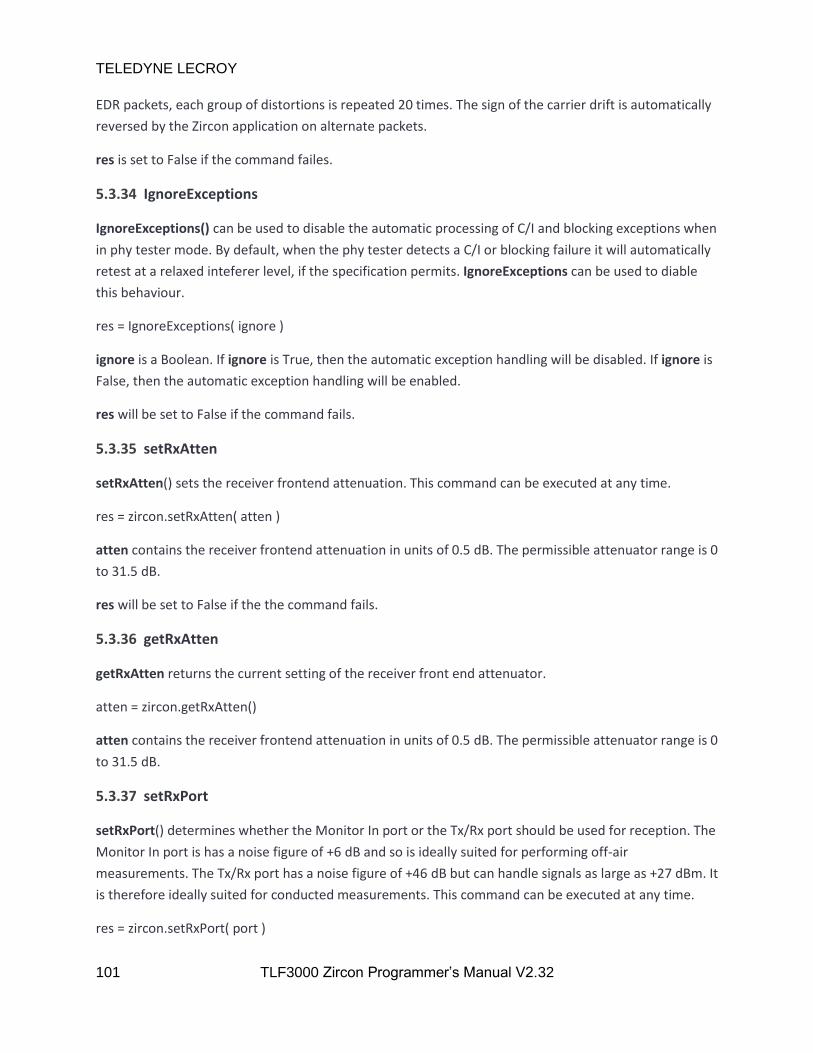
TELEDYNE LECROY
101 TLF3000 Zircon Programmer’s Manual V2.32
EDR packets, each group of distortions is repeated 20 times. The sign of the carrier drift is automatically
reversed by the Zircon application on alternate packets.
res is set to False if the command failes.
5.3.34 IgnoreExceptions
IgnoreExceptions() can be used to disable the automatic processing of C/I and blocking exceptions when
in phy tester mode. By default, when the phy tester detects a C/I or blocking failure it will automatically
retest at a relaxed inteferer level, if the specification permits. IgnoreExceptions can be used to diable
this behaviour.
res = IgnoreExceptions( ignore )
ignore is a Boolean. If ignore is True, then the automatic exception handling will be disabled. If ignore is
False, then the automatic exception handling will be enabled.
res will be set to False if the command fails.
5.3.35 setRxAtten
setRxAtten() sets the receiver frontend attenuation. This command can be executed at any time.
res = zircon.setRxAtten( atten )
atten contains the receiver frontend attenuation in units of 0.5 dB. The permissible attenuator range is 0
to 31.5 dB.
res will be set to False if the the command fails.
5.3.36 getRxAtten
getRxAtten returns the current setting of the receiver front end attenuator.
atten = zircon.getRxAtten()
atten contains the receiver frontend attenuation in units of 0.5 dB. The permissible attenuator range is 0
to 31.5 dB.
5.3.37 setRxPort
setRxPort() determines whether the Monitor In port or the Tx/Rx port should be used for reception. The
Monitor In port is has a noise figure of +6 dB and so is ideally suited for performing off-air
measurements. The Tx/Rx port has a noise figure of +46 dB but can handle signals as large as +27 dBm. It
is therefore ideally suited for conducted measurements. This command can be executed at any time.
res = zircon.setRxPort( port )

TELEDYNE LECROY
102 TLF3000 Zircon Programmer’s Manual V2.32
port is the receiver port to use for reception and can be one of the following values:
0 Monitor In
1 Tx/Rx port
res will be set to False if the the command fails.
5.3.38 getRxPort
getRxPort() returns the port currently in use for reception. The Monitor In port is has a noise figure of +6
dB and so is ideally suited for performing off-air measurements. The Tx/Rx port has a noise figure of +46
dB but can handle signals as large as +27 dBm. It is therefore ideally suited for conducted
measurements. This command can be executed at any time.
port = zircon.getPort()
port is the receiver port used for reception and can be one of the following values:
0 Monitor In
1 Tx/Rx port
5.3.39 setDIOVolts
setDIOVolts() determines whether the digital IO voltage is supplied by TLF3000 or is supplied by an
external source. If TLF3000 supplies the digital IO voltage then it is fixed at 3.3 V. The TLF3000 is able to
provide up to 500 mA on the 3v3 supply. If an external voltage is used for the digital IO then it must be
in the range 0.8 V to 3.6 V. This command can be executed at any time.
res = zircon.setDIOVolts( ext )
ext determines whether the IO voltage is supplied internally or externally:
0 3.3 V IO supplied by TLF3000
1 0.8 V to 3.6 V IO supplied externally
res will be set to False if the the command fails.
5.3.40 getError
getError() returns the oldest error message from the Zircon error queue. Once read, this eror message is
removed from the error queue.
msg = zircon.getError()

TELEDYNE LECROY
103 TLF3000 Zircon Programmer’s Manual V2.32
msg is a string containing the oldest message of the Zircon error queue. If the queue is empty, then an
empty string is returned.
5.3.41 exitApp
exitApp() will cause the Zircon application to exit and control return to the TLF3000 supervistor
program.
res = zircon.exitApp()
res will be set to False if the the command fails.
5.3.42 measCW
measCW instructs the Zircon application to measure the power and frequency of the strongest in-band
CW signal. This can be used to trim the crystal of a DUT on a production line. This command can only be
executed in phy tester mode.
cw = measCW()
cw is a vector_float which must be imported from module Frontline. It contains two elements. The first
element is the frequency of the CW signal in kHz. The second element is the power of the CW signal in
dBm.
5.3.43 hardwareReset
hardwareReset() will cause the TLF3000 to reboot.
zircon.hardwareReset()
5.3.44 powerDown
powerDown() will power down the TLF3000.
zircon.powerDown()
5.3.45 getFriendlyName
getFriendlyName() will return the friendly name of the TLF3000 unit.
name = zircon.getFriendlyName()
name is a string containging the friendly name of the TLF3000 unit.
5.3.46 getSerialNumber
geSerialNumber() will return the serial number of the TLF3000 unit.

TELEDYNE LECROY
104 TLF3000 Zircon Programmer’s Manual V2.32
sn = zircon.getSerialNumber()
sn is an integer containing the serial number of the TLF3000 unit.
5.3.47 stashExe
stashExe() instructs the TLF3000 to place the Zircon image into RAM disc so that it can be quickly
retrieved after another application has been run.
res = zircon.stashExe()
res is set to False if the command fails.
5.3.48 swapExe
swapExe() tells Zircon which application is going to be run next on the TLF3000. This application will be
started when the Zircon application is suspended.
res = zircon.swapExe( num )
num is the application number of the next application to be run.
res is set to False if the command fails.
5.3.49 suspend
suspend() suspends execution of the Zircon application and changes execution to the application
specified in the last swapExe() command.
zircon.suspend()
5.3.50 resume
resume() should be called after another application has swapped execution to the Zircon application.
This causes the resumption of the Zicon application.
zircon.resume()

TELEDYNE LECROY
105 TLF3000 Zircon Programmer’s Manual V2.32
6 C dll Interface
6.1 Overview
Support is provided for driving the TLF3000 using a C dll. This support is available for both 32 bit and 64
bits.
6.1.1 Connecting to the TLF3000
To connect to the TLF3000 it is first necessary to find a list of accessible TLF3000s by calling
zircon_search(). The required TLF3000 can be identified and connected to using zircon_connect(). This
will start the Zircon application running on the TLF3000.
zircon_search_result_t* results; while (true) int N; zircon_search(&results, &N); for (int i = 0; i < N; i++) printf("Found: %d\n", results[i].serial_number); if (N) // This simply connects to the first unit which is found printf("Connecting\n"); zircon_connect(results[0].handle); break; std::this_thread::sleep_for(500ms);
6.1.2 Handling asynchronous data
A callback should be attached to handle asynchronous data from the TLF3000. This is done by calling
zircon_set_data_callback().
// Register callback for asynch data channel zircon_set_data_callback((zircon_data_callback_t)&dataCallback);
Whenever an asynchronous message is received from the TLF3000, the asynchronous data callback will
be entered. In the example below, the data is unpacked to determine its length and type. Having
determined the message type, it is dispatched to an appropriate routine. deserialise is a utility function
provided by Frontline to unpack the data returned in the callback.

TELEDYNE LECROY
106 TLF3000 Zircon Programmer’s Manual V2.32
void dataCallback(uint8_t *data, uint32_t len) std::vector<unsigned char> d; for (uint32_t k = 0; k < len; k++) d.push_back(data[k]); uint16_t len_lsb; uint8_t len_msb; uint8_t type; deserialise(d, len_lsb, len_msb, type); switch (type) case 0: StartScript(d); break; case 1: TxTest(d); break; case 2: RxTest(d); break; case 3: EndScript(d); break; case 4: StartLine(d); break; case 5: EndLine(d); break; case 65: InquiryComplete(d); break; case 66: InquiryResponse(d); break; case 67: PageComplete(d); break; case 69: DUTname(d); break; case 99: break; case 110: break; // GUI specific callback case 193: EnvData(d); break; case 194: PwrData(d); break; default: printf("Unknown callback %d\n", type); break;
6.1.3 Handling errors
Many of the calls to the Zircon library return a flag to indicate wtheter the call was successful or not.
When an error occurs, the cause of the error can be read back by calling zircon_getError(). Each
invocation of this method will remove the oldest error from the Zircon error queue and return it to the
caller. When no more messages are available, an empty string is returned.
void getError() char err[1024]; zircon_getError(err,1024); while (err[0]) printf("%s\n", err); zircon_getError(err,1024);
6.1.4 Closing down
The Zircon application can be shutdown by calling zircon_disconnect()
zircon_disconnect();
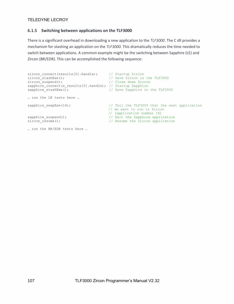
TELEDYNE LECROY
107 TLF3000 Zircon Programmer’s Manual V2.32
6.1.5 Switching between applications on the TLF3000
There is a significant overhead in downloading a new application to the TLF3000. The C dll provides a
mechanism for stashing an application on the TLF3000. This dramatically reduces the time needed to
switch between applications. A common example might be the switching between Sapphire (LE) and
Zircon (BR/EDR). This can be accomplished the following sequence:
zircon_connect(results[0].handle); // Startup Zircon
zircon_stashExe(); // Save Zircon in the TLF3000
zircon_suspend(); // Close down Zircon
sapphire_connect(s_results[0].handle); // Startup Sapphire
sapphire_stashExe(); // Save Sapphire in the TLF3000
… run the LE tests here …
sapphire_swapExe(16); // Tell the TLF3000 that the next application
// we want to run is Zircon
// (application number 16)
sapphire_suspend(); // Exit the Sapphire application
zircon_resume(); // Resume the Zircon application
… run the BR/EDR tests here …
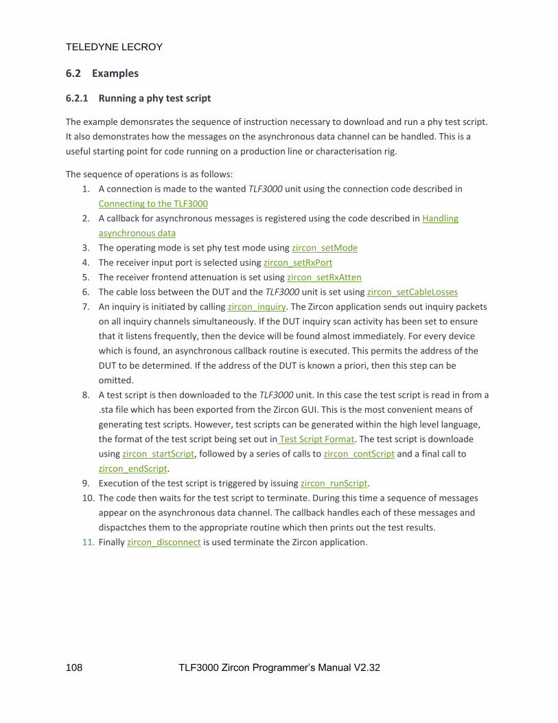
TELEDYNE LECROY
108 TLF3000 Zircon Programmer’s Manual V2.32
6.2 Examples
6.2.1 Running a phy test script
The example demonsrates the sequence of instruction necessary to download and run a phy test script.
It also demonstrates how the messages on the asynchronous data channel can be handled. This is a
useful starting point for code running on a production line or characterisation rig.
The sequence of operations is as follows:
1. A connection is made to the wanted TLF3000 unit using the connection code described in
Connecting to the TLF3000
2. A callback for asynchronous messages is registered using the code described in Handling
asynchronous data
3. The operating mode is set phy test mode using zircon_setMode
4. The receiver input port is selected using zircon_setRxPort
5. The receiver frontend attenuation is set using zircon_setRxAtten
6. The cable loss between the DUT and the TLF3000 unit is set using zircon_setCableLosses
7. An inquiry is initiated by calling zircon_inquiry. The Zircon application sends out inquiry packets
on all inquiry channels simultaneously. If the DUT inquiry scan activity has been set to ensure
that it listens frequently, then the device will be found almost immediately. For every device
which is found, an asynchronous callback routine is executed. This permits the address of the
DUT to be determined. If the address of the DUT is known a priori, then this step can be
omitted.
8. A test script is then downloaded to the TLF3000 unit. In this case the test script is read in from a
.sta file which has been exported from the Zircon GUI. This is the most convenient means of
generating test scripts. However, test scripts can be generated within the high level language,
the format of the test script being set out in Test Script Format. The test script is downloade
using zircon_startScript, followed by a series of calls to zircon_contScript and a final call to
zircon_endScript.
9. Execution of the test script is triggered by issuing zircon_runScript.
10. The code then waits for the test script to terminate. During this time a sequence of messages
appear on the asynchronous data channel. The callback handles each of these messages and
dispactches them to the appropriate routine which then prints out the test results.
11. Finally zircon_disconnect is used terminate the Zircon application.
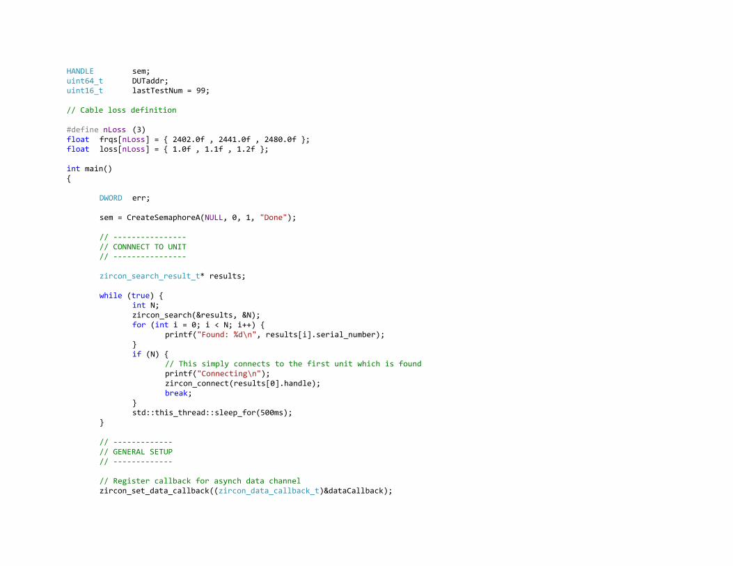
HANDLE sem; uint64_t DUTaddr; uint16_t lastTestNum = 99; // Cable loss definition #define nLoss (3) float frqs[nLoss] = 2402.0f , 2441.0f , 2480.0f ; float loss[nLoss] = 1.0f , 1.1f , 1.2f ; int main() DWORD err; sem = CreateSemaphoreA(NULL, 0, 1, "Done"); // ---------------- // CONNNECT TO UNIT // ---------------- zircon_search_result_t* results; while (true) int N; zircon_search(&results, &N); for (int i = 0; i < N; i++) printf("Found: %d\n", results[i].serial_number); if (N) // This simply connects to the first unit which is found printf("Connecting\n"); zircon_connect(results[0].handle); break; std::this_thread::sleep_for(500ms); // ------------- // GENERAL SETUP // ------------- // Register callback for asynch data channel zircon_set_data_callback((zircon_data_callback_t)&dataCallback);

TELEDYNE LECROY
110 TLF3000 Zircon Programmer’s Manual V2.32
// Enter loopback tester mode if (zircon_setMode(0) != ZIRCON_NO_ERROR) getError(); // Set rx frontend attenuation in units of 0.5dB if (zircon_setRxAtten(0) != ZIRCON_NO_ERROR) getError(); // Set the rx port to be tx / rx if (zircon_setRxPort(1) != ZIRCON_NO_ERROR) getError(); // Set cable loss if (zircon_setCableLosses( nLoss, frqs, loss ) != ZIRCON_NO_ERROR) getError(); // -------------------------------------------------------------------------------- // DO AN INQUIRY TO FIND THE DUT (not required if the DUT address is already known) // -------------------------------------------------------------------------------- DUTaddr = 0; while (!DUTaddr) // arg1 = Time duration of inquiry in ms // arg2 = Inquiry power per channel in unit of 0.1 dBm // arg3 = RSSI threshold for inquiry responses in dBm // arg4 = Expected number of responses if (zircon_inquiry(10000, -400, -40, 1) != ZIRCON_NO_ERROR) getError(); err = WaitForSingleObject(sem, 11000); if (err != WAIT_OBJECT_0) printf("Error waiting for inquiry to complete\n"); if (!DUTaddr) printf("No DUT found ... press return to try again\n"); getchar(); // ------------------------ // RUN THE MAIN TEST SCRIPT // ------------------------ // Start download of test script // arg1 = Overwrite file with existing name

TELEDYNE LECROY
111 TLF3000 Zircon Programmer’s Manual V2.32
// arg2 = Do not place in FLASH(currently not supported) // arg3 = Test script file name if (zircon_startScript(true, false, "TestScript") != ZIRCON_NO_ERROR) getError(); FILE *fid; fopen_s(&fid, "D:/Users/timbo/Docs/test.sta", "rt"); char line[4096]; while (fgets(line, 4096, fid)) // Add lines to test script file if (zircon_contScript(line) != ZIRCON_NO_ERROR) getError(); fclose(fid); // Signal that the test script is now complete if (zircon_endScript() != ZIRCON_NO_ERROR) getError(); // Run the test script // arg1 = Bluetooth address of DUT // arg2 = Paging timeout in ms // arg3 = Paging power in 0.1dBm // arg4 = LMP packet power in 0.1dBm // arg5 = Power used for poll packets in transmit mode in 0.1dBm // arg6 = Supervsision timeout in ms // arg7 = Number of times script should be run // arg8 = Run to completion flag // arg9 = Test only against limits to save test time // arg10 = Unimplemented flag - ignored // arg11 = Test script file nane - same as in startScript call lastTestNum = 99; uint32_t DUTnap = (DUTaddr >> 32); uint32_t DUTuap = (DUTaddr >> 24) & 0xFF; uint32_t DUTlap = (DUTaddr & 0xFFFFFF); if (zircon_runScript(DUTlap, DUTuap, DUTnap, 10000, -450, -450, -400, -40, 250, 1, true, true, false, (char *) "TestScript") != ZIRCON_NO_ERROR) getError(); // YOU WILL NEED TO ADJUST THIS TIMEOUT DEPENDING ON HOW LONG YOU THINK YOUR TEST SCRIPT WILL TAKE TO RUN err = WaitForSingleObject(sem, 20000); if (err != WAIT_OBJECT_0) printf("Error waiting for script to terminate\n"); // getError();

TELEDYNE LECROY
112 TLF3000 Zircon Programmer’s Manual V2.32
// ------- // Tidy up // ------- // Stop the Zircon application running on the unit zircon_disconnect(); printf("All done\n"); getchar(); return 0;

6.2.1.1 Inquiry and associated callbacks
The inquiry complete callback is invoked whenever an inquiry terminates. An inquiry will terminate
either after a specified number of devices have been found or a specified time interval has expired.
void InquiryComplete(std::vector<unsigned char> d) printf("Inquiry completed\n"); ReleaseSemaphore(sem, 1, NULL);
The inquiry response callback is invoked everytime a new DUT is discovered. It allows the address of the
DUT to be determined. It also returns the RSSI of the DUT inquiry response so it can be determined
whether the DUT is nearby or not.
void InquiryResponse(std::vector<unsigned char> d) uint32_t hdr; uint16_t n; int8_t rssi; int8_t dummy; uint32_t addr_msb; uint32_t addr_lsb; deserialise(d, hdr, n, rssi, dummy, addr_msb, addr_lsb); DUTaddr = addr_msb; DUTaddr <<= 32; DUTaddr |= addr_lsb; printf("Inquiry response from device %012I64X with RSSI %d dBm\n", DUTaddr, rssi);
The page complete callback is invoked when the connection between the Zircon application and the
DUT is terminated.
void PageComplete(std::vector<unsigned char> d) printf("Paging completed\n");
The DUT name callback is invoked when the Zircon application connects to the DUT and successfully
reads back the DUTs name.
void DUTname(std::vector<unsigned char> d) std::vector<char> x; deserialise(d, Pad<8>(), x); if (x.size() < 4) return; x[x.size() - 4] = 0; printf("DUT name is %s\n", x.data());

TELEDYNE LECROY
114 TLF3000 Zircon Programmer’s Manual V2.32
6.2.1.2 Test progress
The progress of the testing is reported via asynchronous callbacks. Callbacks are generated whenever:
1. A new script is started.
2. A new line in a script is started.
3. A line in a script is completed, with an indication of pass or fail.
4. A script is completed, with an indication of pass or fail.
void StartScript(std::vector<unsigned char> d) uint32_t hdr; uint16_t unused; uint8_t id; uint8_t ok; deserialise(d, hdr, unused, id, ok); printf("Test script execution starting : %d\n", id); void EndScript(std::vector<unsigned char> d) uint32_t hdr; uint16_t unused; uint8_t id; uint8_t ok; deserialise(d, hdr, unused, id, ok); printf("Test script execution terminating : %d\n", id); if (ok) printf("Test script result : FAIL\n"); else printf("Test script result : PASS\n"); ReleaseSemaphore(sem, 1, NULL); void StartLine(std::vector<unsigned char> d) uint32_t hdr; uint16_t line; uint8_t id; uint8_t num; deserialise(d, hdr, line, id, num); printf("Starting test script line %d\n", line); void EndLine(std::vector<unsigned char> d) uint32_t hdr; uint16_t line; uint8_t id; uint8_t num; uint32_t result; deserialise(d, hdr, line, id, num, result); printf("End test script line %d", line); if (result == 0) printf(" : FAIL\n"); else printf(" : PASS\n");

TELEDYNE LECROY
115 TLF3000 Zircon Programmer’s Manual V2.32
6.2.1.3 Tables for decoding results
The example code utilises the following tables to decode the test results returned.
// Text strings for output static const char *PktNames[28] = "ID", "NULL", "POLL", "FHS", "DM1", "DH1", "DM3", "DH3", "DM5", "DH5", "AUX1", "2-DH1", "2-DH3", "2-DH5", "3-DH1", "3-DH3", "3-DH5", "HV1", "HV2", "HV3", "DV", "EV3", "EV4", "EV5", "2-EV3", "2-EV5", "3-EV3", "3-EV5" ; static const char *PktPayloads[8] = "PRBS9", "11110000", "10101010", "11111111", "00000000", "????????", "????????", "????????" ;
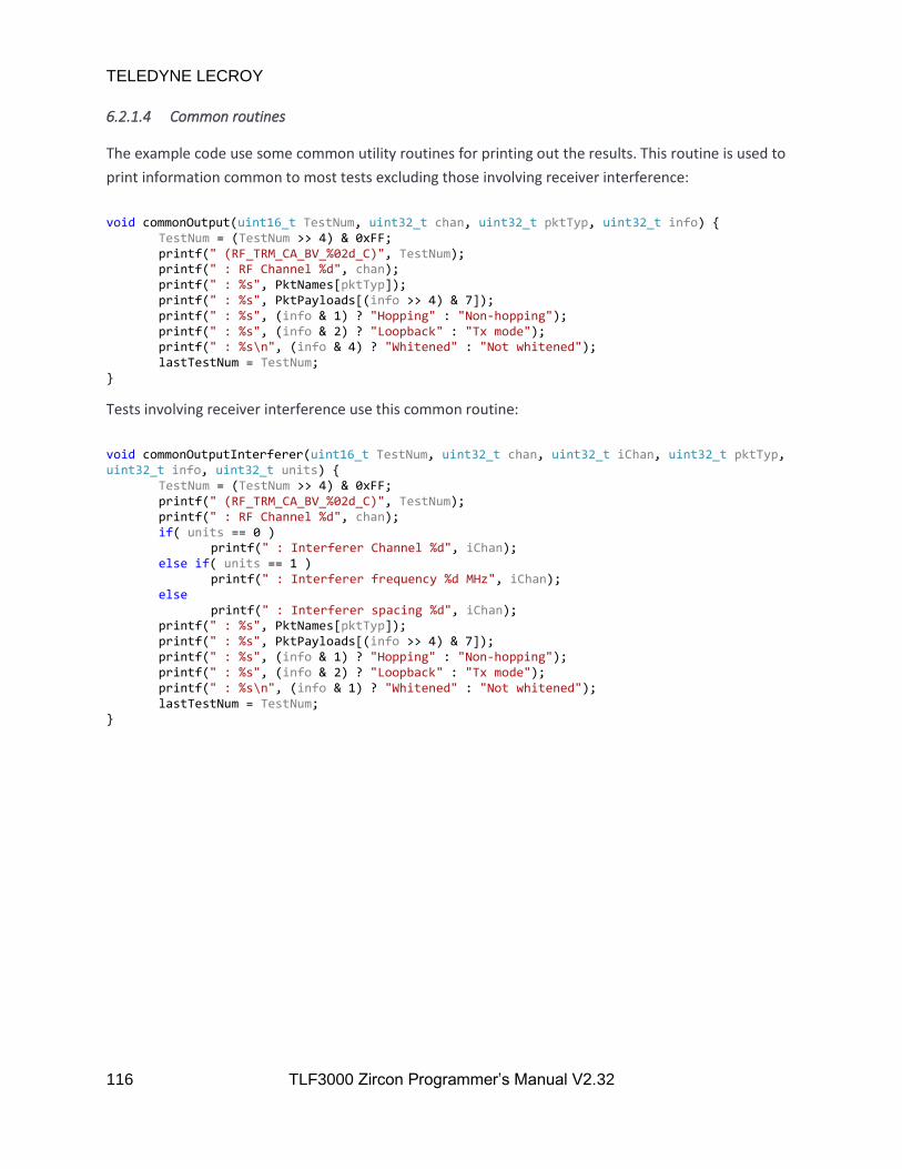
TELEDYNE LECROY
116 TLF3000 Zircon Programmer’s Manual V2.32
6.2.1.4 Common routines
The example code use some common utility routines for printing out the results. This routine is used to
print information common to most tests excluding those involving receiver interference:
void commonOutput(uint16_t TestNum, uint32_t chan, uint32_t pktTyp, uint32_t info) TestNum = (TestNum >> 4) & 0xFF; printf(" (RF_TRM_CA_BV_%02d_C)", TestNum); printf(" : RF Channel %d", chan); printf(" : %s", PktNames[pktTyp]); printf(" : %s", PktPayloads[(info >> 4) & 7]); printf(" : %s", (info & 1) ? "Hopping" : "Non-hopping"); printf(" : %s", (info & 2) ? "Loopback" : "Tx mode"); printf(" : %s\n", (info & 4) ? "Whitened" : "Not whitened"); lastTestNum = TestNum;
Tests involving receiver interference use this common routine:
void commonOutputInterferer(uint16_t TestNum, uint32_t chan, uint32_t iChan, uint32_t pktTyp, uint32_t info, uint32_t units) TestNum = (TestNum >> 4) & 0xFF; printf(" (RF_TRM_CA_BV_%02d_C)", TestNum); printf(" : RF Channel %d", chan); if( units == 0 ) printf(" : Interferer Channel %d", iChan); else if( units == 1 ) printf(" : Interferer frequency %d MHz", iChan); else printf(" : Interferer spacing %d", iChan); printf(" : %s", PktNames[pktTyp]); printf(" : %s", PktPayloads[(info >> 4) & 7]); printf(" : %s", (info & 1) ? "Hopping" : "Non-hopping"); printf(" : %s", (info & 2) ? "Loopback" : "Tx mode"); printf(" : %s\n", (info & 1) ? "Whitened" : "Not whitened"); lastTestNum = TestNum;
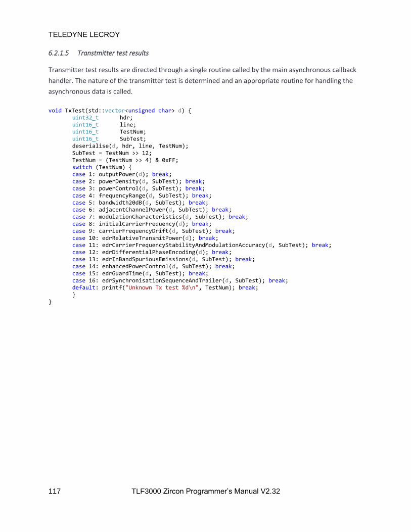
TELEDYNE LECROY
117 TLF3000 Zircon Programmer’s Manual V2.32
6.2.1.5 Transtmitter test results
Transmitter test results are directed through a single routine called by the main asynchronous callback
handler. The nature of the transmitter test is determined and an appropriate routine for handling the
asynchronous data is called.
void TxTest(std::vector<unsigned char> d) uint32_t hdr; uint16_t line; uint16_t TestNum; uint16_t SubTest; deserialise(d, hdr, line, TestNum); SubTest = TestNum >> 12; TestNum = (TestNum >> 4) & 0xFF; switch (TestNum) case 1: outputPower(d); break; case 2: powerDensity(d, SubTest); break; case 3: powerControl(d, SubTest); break; case 4: frequencyRange(d, SubTest); break; case 5: bandwidth20dB(d, SubTest); break; case 6: adjacentChannelPower(d, SubTest); break; case 7: modulationCharacteristics(d, SubTest); break; case 8: initialCarrierFrequency(d); break; case 9: carrierFrequencyDrift(d, SubTest); break; case 10: edrRelativeTransmitPower(d); break; case 11: edrCarrierFrequencyStabilityAndModulationAccuracy(d, SubTest); break; case 12: edrDifferentialPhaseEncoding(d); break; case 13: edrInBandSpuriousEmissions(d, SubTest); break; case 14: enhancedPowerControl(d, SubTest); break; case 15: edrGuardTime(d, SubTest); break; case 16: edrSynchronisationSequenceAndTrailer(d, SubTest); break; default: printf("Unknown Tx test %d\n", TestNum); break;

TELEDYNE LECROY
118 TLF3000 Zircon Programmer’s Manual V2.32
6.2.1.5.1 Transmitter output power results
Measurements related to output power are decoded by the following routine:
// Callback for tx output power messages void outputPower(std::vector<unsigned char> d) uint32_t hdr; uint16_t line; uint16_t TestNum; uint32_t chan; uint32_t info; uint32_t pktTyp; float Pmin; float Pmax; float Lmin; float Lmax; uint32_t result; deserialise(d, hdr, line, TestNum, chan, info, pktTyp, Pmin, Pmax, Lmin, Lmax, result); printf(" Output Power"); commonOutput(TestNum, chan, pktTyp, info); printf(" Minimum power : %.1f dBm", Pmin); printf(" ( %s )\n", (result & 2) ? "FAIL" : "PASS"); printf(" Maximum power : %.1f dBm", Pmax); printf(" ( %s )\n", (result & 4) ? "FAIL" : "PASS");
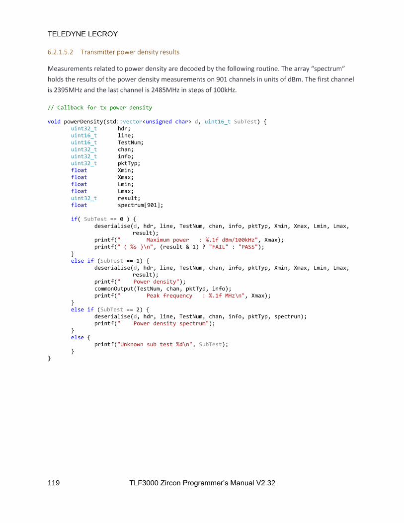
TELEDYNE LECROY
119 TLF3000 Zircon Programmer’s Manual V2.32
6.2.1.5.2 Transmitter power density results
Measurements related to power density are decoded by the following routine. The array “spectrum”
holds the results of the power density measurements on 901 channels in units of dBm. The first channel
is 2395MHz and the last channel is 2485MHz in steps of 100kHz.
// Callback for tx power density void powerDensity(std::vector<unsigned char> d, uint16_t SubTest) uint32_t hdr; uint16_t line; uint16_t TestNum; uint32_t chan; uint32_t info; uint32_t pktTyp; float Xmin; float Xmax; float Lmin; float Lmax; uint32_t result; float spectrum[901]; if( SubTest == 0 ) deserialise(d, hdr, line, TestNum, chan, info, pktTyp, Xmin, Xmax, Lmin, Lmax, result); printf(" Maximum power : %.1f dBm/100kHz", Xmax); printf(" ( %s )\n", (result & 1) ? "FAIL" : "PASS"); else if (SubTest == 1) deserialise(d, hdr, line, TestNum, chan, info, pktTyp, Xmin, Xmax, Lmin, Lmax, result); printf(" Power density"); commonOutput(TestNum, chan, pktTyp, info); printf(" Peak frequency : %.1f MHz\n", Xmax); else if (SubTest == 2) deserialise(d, hdr, line, TestNum, chan, info, pktTyp, spectrun); printf(" Power density spectrum"); else printf("Unknown sub test %d\n", SubTest);
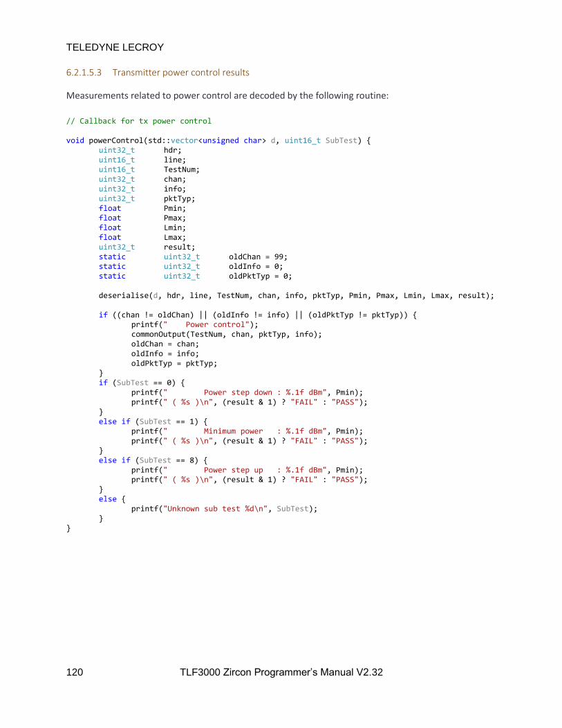
TELEDYNE LECROY
120 TLF3000 Zircon Programmer’s Manual V2.32
6.2.1.5.3 Transmitter power control results
Measurements related to power control are decoded by the following routine:
// Callback for tx power control void powerControl(std::vector<unsigned char> d, uint16_t SubTest) uint32_t hdr; uint16_t line; uint16_t TestNum; uint32_t chan; uint32_t info; uint32_t pktTyp; float Pmin; float Pmax; float Lmin; float Lmax; uint32_t result; static uint32_t oldChan = 99; static uint32_t oldInfo = 0; static uint32_t oldPktTyp = 0; deserialise(d, hdr, line, TestNum, chan, info, pktTyp, Pmin, Pmax, Lmin, Lmax, result); if ((chan != oldChan) || (oldInfo != info) || (oldPktTyp != pktTyp)) printf(" Power control"); commonOutput(TestNum, chan, pktTyp, info); oldChan = chan; oldInfo = info; oldPktTyp = pktTyp; if (SubTest == 0) printf(" Power step down : %.1f dBm", Pmin); printf(" ( %s )\n", (result & 1) ? "FAIL" : "PASS"); else if (SubTest == 1) printf(" Minimum power : %.1f dBm", Pmin); printf(" ( %s )\n", (result & 1) ? "FAIL" : "PASS"); else if (SubTest == 8) printf(" Power step up : %.1f dBm", Pmin); printf(" ( %s )\n", (result & 1) ? "FAIL" : "PASS"); else printf("Unknown sub test %d\n", SubTest);

TELEDYNE LECROY
121 TLF3000 Zircon Programmer’s Manual V2.32
6.2.1.5.4 Transmitter frequency range results
Measurements related to frequency range are decoded by the following routine. The spectrum arrays
have a resolution of 100kHz and span 10MHz, starting at either 2395MHz or 2475MHz. They contain the
measured power in units of dBm.
// Callback for tx frequency range void frequencyRange(std::vector<unsigned char> d, uint16_t SubTest) uint32_t hdr; uint16_t line; uint16_t TestNum; uint32_t chan; uint32_t info; uint32_t pktTyp; float X; float L; uint32_t result; float spectrum[101]; if (SubTest == 0) deserialise(d, hdr, line, TestNum, chan, info, pktTyp, X, L, result); printf(" Minimum range : %.1f MHz", X); printf(" ( %s )\n", (result & 1) ? "FAIL" : "PASS"); else if (SubTest == 1) deserialise(d, hdr, line, TestNum, chan, info, pktTyp, X, L, result); printf(" Frequency range"); commonOutput(TestNum, chan, pktTyp, info); printf(" Maximum range : %.1f MHz", X); printf(" ( %s )\n", (result & 1) ? "FAIL" : "PASS"); else if (SubTest == 2) deserialise(d, hdr, line, TestNum, chan, info, pktTyp, spectrum); else printf("Unknown sub test %d\n", SubTest);
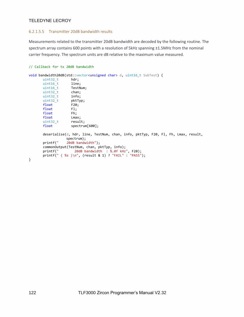
TELEDYNE LECROY
122 TLF3000 Zircon Programmer’s Manual V2.32
6.2.1.5.5 Transmitter 20dB bandwidth results
Measurements related to the transmitter 20dB bandwidth are decoded by the following routine. The
spectrum array contains 600 points with a resolution of 5kHz spanning ±1.5MHz from the nominal
carrier frequency. The spectrum units are dB relative to the maximum value measured.
// Callback for tx 20dB bandwidth void bandwidth20dB(std::vector<unsigned char> d, uint16_t SubTest) uint32_t hdr; uint16_t line; uint16_t TestNum; uint32_t chan; uint32_t info; uint32_t pktTyp; float F20; float Fl; float Fh; float Lmax; uint32_t result; float spectrum[600]; deserialise(d, hdr, line, TestNum, chan, info, pktTyp, F20, Fl, Fh, Lmax, result, spectrum); printf(" 20dB bandwidth"); commonOutput(TestNum, chan, pktTyp, info); printf(" 20dB bandwidth : %.0f kHz", F20); printf(" ( %s )\n", (result & 1) ? "FAIL" : "PASS");

TELEDYNE LECROY
123 TLF3000 Zircon Programmer’s Manual V2.32
6.2.1.5.6 Transmitter adjacent channel power results
Measurements related to the transmitter adjacent channel power are decoded by the following routine.
Two spectra are returned. The first contains the ACP measurements every 1MHz from 2395MHz to
2485MHz inclusive. The second contains the 100kHz RBW measurements which were used to generate
the 1MHz resolution results. These measurements are from 2394.550MHz to 2485.450MHz in 100kHz
steps.
// Callback for tx adjacent channel power void adjacentChannelPower(std::vector<unsigned char> d, uint16_t SubTest) uint32_t hdr; uint16_t line; uint16_t TestNum; uint32_t chan; uint32_t info; uint32_t pktTyp; float Pmin; float Pmax; float Lmin; float Lmax; uint32_t result; float spectrum[91]; static uint16_t oldSubTest = 99; if( SubTest == 1 ) deserialise(d, hdr, line, TestNum, chan, info, pktTyp, Pmin, Pmax, Lmin, Lmax, result); printf(" | M - N | = 2 : %.1f dBm", Pmax); printf(" ( %s )\n", (result & 1) ? "FAIL" : "PASS"); else if (SubTest == 2) deserialise(d, hdr, line, TestNum, chan, info, pktTyp, Pmin, Pmax, Lmin, Lmax, result); printf(" | M - N | >= 3 : %.1f dBm", Pmax); printf(" ( %s )\n", (result & 1) ? "FAIL" : "PASS"); else if (SubTest == 3) deserialise(d, hdr, line, TestNum, chan, info, pktTyp, Pmin, Pmax, Lmin, Lmax, result); if (oldSubTest != 4) printf(" Adjacent channel power"); commonOutput(TestNum, chan, pktTyp, info); printf(" # exceptions : %.0f", Pmax); printf(" ( %s )\n", (result & 1) ? "FAIL" : "PASS"); else if (SubTest == 4) deserialise(d, hdr, line, TestNum, chan, info, pktTyp, Pmin, Pmax, Lmin, Lmax, result); printf(" Adjacent channel power"); commonOutput(TestNum, chan, pktTyp, info); printf(" Max exception : %.1f dBm", Pmax); printf(" ( %s )\n", (result & 1) ? "FAIL" : "PASS"); else if (SubTest == 5) deserialise(d, hdr, line, TestNum, chan, info, pktTyp, spectrum);

TELEDYNE LECROY
124 TLF3000 Zircon Programmer’s Manual V2.32
else printf("Unknown sub test %d\n", SubTest); oldSubTest = SubTest;
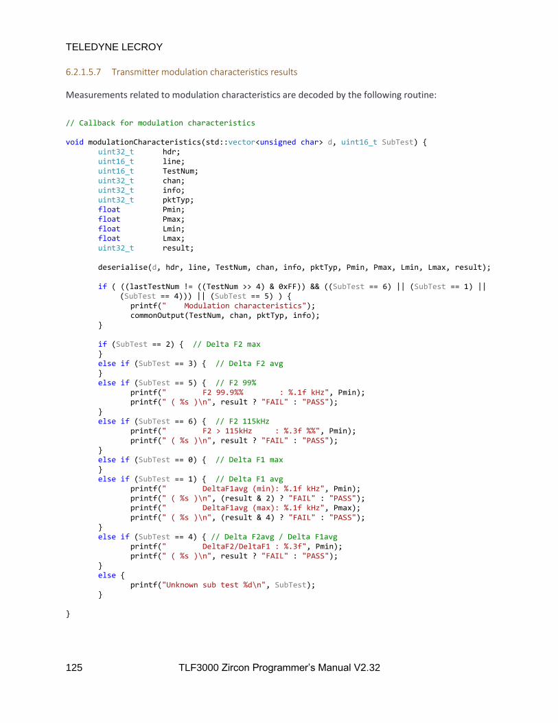
TELEDYNE LECROY
125 TLF3000 Zircon Programmer’s Manual V2.32
6.2.1.5.7 Transmitter modulation characteristics results
Measurements related to modulation characteristics are decoded by the following routine:
// Callback for modulation characteristics void modulationCharacteristics(std::vector<unsigned char> d, uint16_t SubTest) uint32_t hdr; uint16_t line; uint16_t TestNum; uint32_t chan; uint32_t info; uint32_t pktTyp; float Pmin; float Pmax; float Lmin; float Lmax; uint32_t result; deserialise(d, hdr, line, TestNum, chan, info, pktTyp, Pmin, Pmax, Lmin, Lmax, result); if ( ((lastTestNum != ((TestNum >> 4) & 0xFF)) && ((SubTest == 6) || (SubTest == 1) || (SubTest == 4))) || (SubTest == 5) ) printf(" Modulation characteristics"); commonOutput(TestNum, chan, pktTyp, info); if (SubTest == 2) // Delta F2 max else if (SubTest == 3) // Delta F2 avg else if (SubTest == 5) // F2 99% printf(" F2 99.9%% : %.1f kHz", Pmin); printf(" ( %s )\n", result ? "FAIL" : "PASS"); else if (SubTest == 6) // F2 115kHz printf(" F2 > 115kHz : %.3f %%", Pmin); printf(" ( %s )\n", result ? "FAIL" : "PASS"); else if (SubTest == 0) // Delta F1 max else if (SubTest == 1) // Delta F1 avg printf(" DeltaF1avg (min): %.1f kHz", Pmin); printf(" ( %s )\n", (result & 2) ? "FAIL" : "PASS"); printf(" DeltaF1avg (max): %.1f kHz", Pmax); printf(" ( %s )\n", (result & 4) ? "FAIL" : "PASS"); else if (SubTest == 4) // Delta F2avg / Delta F1avg printf(" DeltaF2/DeltaF1 : %.3f", Pmin); printf(" ( %s )\n", result ? "FAIL" : "PASS"); else printf("Unknown sub test %d\n", SubTest);
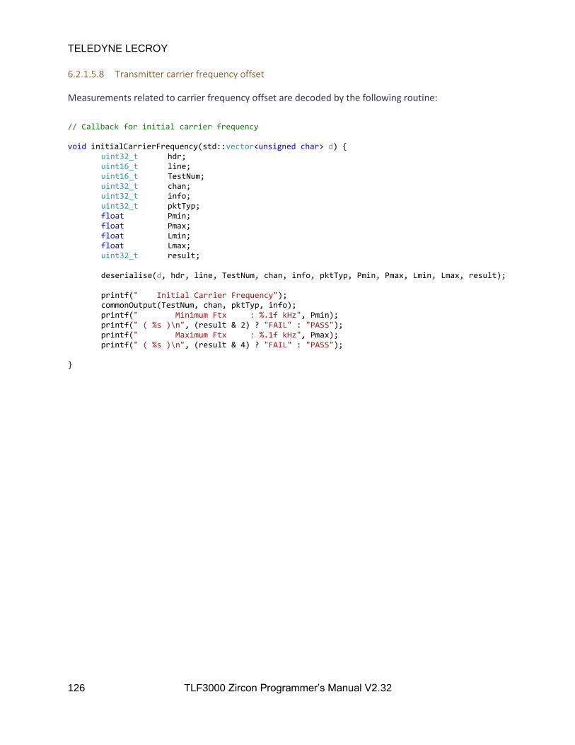
TELEDYNE LECROY
126 TLF3000 Zircon Programmer’s Manual V2.32
6.2.1.5.8 Transmitter carrier frequency offset
Measurements related to carrier frequency offset are decoded by the following routine:
// Callback for initial carrier frequency void initialCarrierFrequency(std::vector<unsigned char> d) uint32_t hdr; uint16_t line; uint16_t TestNum; uint32_t chan; uint32_t info; uint32_t pktTyp; float Pmin; float Pmax; float Lmin; float Lmax; uint32_t result; deserialise(d, hdr, line, TestNum, chan, info, pktTyp, Pmin, Pmax, Lmin, Lmax, result); printf(" Initial Carrier Frequency"); commonOutput(TestNum, chan, pktTyp, info); printf(" Minimum Ftx : %.1f kHz", Pmin); printf(" ( %s )\n", (result & 2) ? "FAIL" : "PASS"); printf(" Maximum Ftx : %.1f kHz", Pmax); printf(" ( %s )\n", (result & 4) ? "FAIL" : "PASS");

TELEDYNE LECROY
127 TLF3000 Zircon Programmer’s Manual V2.32
6.2.1.5.9 Transmitter carrier frequency drift
Measurements related to carrier frequency drift are decoded by the following routine:
// Callback for carrier frequency drift void carrierFrequencyDrift(std::vector<unsigned char> d, uint16_t SubTest) uint32_t hdr; uint16_t line; uint16_t TestNum; uint32_t chan; uint32_t info; uint32_t pktTyp; float Pmin; float Pmax; float Lmin; float Lmax; uint32_t result; deserialise(d, hdr, line, TestNum, chan, info, pktTyp, Pmin, Pmax, Lmin, Lmax, result); if (SubTest == 0) printf(" Carrier frequency drift"); commonOutput(TestNum, chan, pktTyp, info); printf(" Minimum Fo - Fk : %.1f kHz", Pmin); printf(" ( %s )\n", (result & 2) ? "FAIL" : "PASS"); printf(" Maximum Fo - Fk : %.1f kHz", Pmax); printf(" ( %s )\n", (result & 4) ? "FAIL" : "PASS"); else if (SubTest == 1) printf(" Minimum Fk+5-Fk : %.1f kHz", Pmin); printf(" ( %s )\n", (result & 2) ? "FAIL" : "PASS"); printf(" Maximum Fk+5-Fk : %.1f kHz", Pmax); printf(" ( %s )\n", (result & 4) ? "FAIL" : "PASS"); else printf("Unknown sub test %d\n", SubTest);

TELEDYNE LECROY
128 TLF3000 Zircon Programmer’s Manual V2.32
6.2.1.5.10 Transmitter EDR relative transmit power
Measurements related to EDR relative transmit power are decoded by the following routine:
// Callback for tx EDR relative transmit power
void edrRelativeTransmitPower(std::vector<unsigned char> d) uint32_t hdr; uint16_t line; uint16_t TestNum; uint32_t chan; uint32_t info; uint32_t pktTyp; float Pmin; float Pmax; float Lmin; float Lmax; uint32_t result; deserialise(d, hdr, line, TestNum, chan, info, pktTyp, Pmin, Pmax, Lmin, Lmax, result); printf(" EDR relative tansmit power"); commonOutput(TestNum, chan, pktTyp, info); printf(" Min PDPSK-PGSFK : %.1f dBm", Pmin); printf(" ( %s )\n", (result & 2) ? "FAIL" : "PASS"); printf(" Max PDPSK-PGSFK : %.1f dBm", Pmax); printf(" ( %s )\n", (result & 4) ? "FAIL" : "PASS");
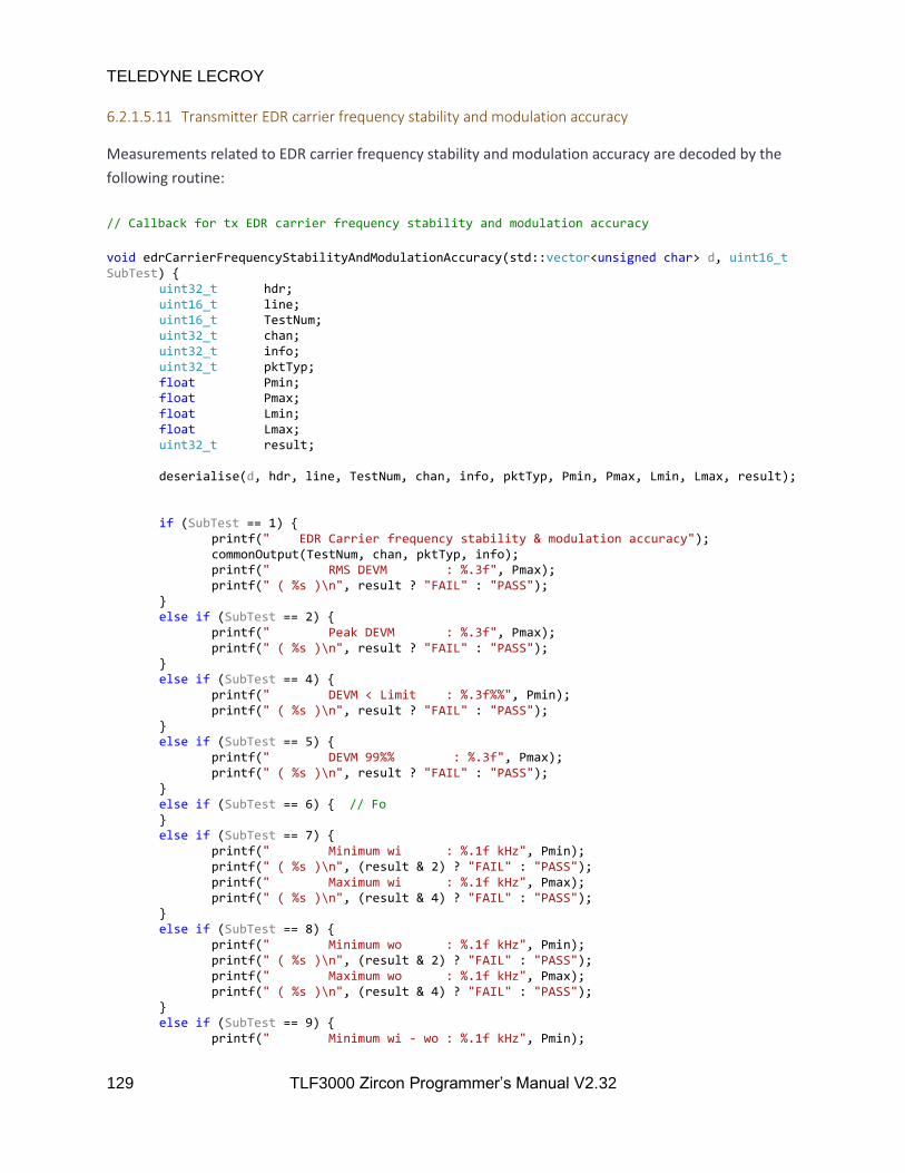
TELEDYNE LECROY
129 TLF3000 Zircon Programmer’s Manual V2.32
6.2.1.5.11 Transmitter EDR carrier frequency stability and modulation accuracy
Measurements related to EDR carrier frequency stability and modulation accuracy are decoded by the
following routine:
// Callback for tx EDR carrier frequency stability and modulation accuracy
void edrCarrierFrequencyStabilityAndModulationAccuracy(std::vector<unsigned char> d, uint16_t SubTest) uint32_t hdr; uint16_t line; uint16_t TestNum; uint32_t chan; uint32_t info; uint32_t pktTyp; float Pmin; float Pmax; float Lmin; float Lmax; uint32_t result; deserialise(d, hdr, line, TestNum, chan, info, pktTyp, Pmin, Pmax, Lmin, Lmax, result); if (SubTest == 1) printf(" EDR Carrier frequency stability & modulation accuracy"); commonOutput(TestNum, chan, pktTyp, info); printf(" RMS DEVM : %.3f", Pmax); printf(" ( %s )\n", result ? "FAIL" : "PASS"); else if (SubTest == 2) printf(" Peak DEVM : %.3f", Pmax); printf(" ( %s )\n", result ? "FAIL" : "PASS"); else if (SubTest == 4) printf(" DEVM < Limit : %.3f%%", Pmin); printf(" ( %s )\n", result ? "FAIL" : "PASS"); else if (SubTest == 5) printf(" DEVM 99%% : %.3f", Pmax); printf(" ( %s )\n", result ? "FAIL" : "PASS"); else if (SubTest == 6) // Fo else if (SubTest == 7) printf(" Minimum wi : %.1f kHz", Pmin); printf(" ( %s )\n", (result & 2) ? "FAIL" : "PASS"); printf(" Maximum wi : %.1f kHz", Pmax); printf(" ( %s )\n", (result & 4) ? "FAIL" : "PASS"); else if (SubTest == 8) printf(" Minimum wo : %.1f kHz", Pmin); printf(" ( %s )\n", (result & 2) ? "FAIL" : "PASS"); printf(" Maximum wo : %.1f kHz", Pmax); printf(" ( %s )\n", (result & 4) ? "FAIL" : "PASS"); else if (SubTest == 9) printf(" Minimum wi - wo : %.1f kHz", Pmin);

TELEDYNE LECROY
130 TLF3000 Zircon Programmer’s Manual V2.32
printf(" ( %s )\n", (result & 2) ? "FAIL" : "PASS"); printf(" Maximum wi - wo : %.1f kHz", Pmax); printf(" ( %s )\n", (result & 4) ? "FAIL" : "PASS"); else printf("Unknown sub test %d\n", SubTest);
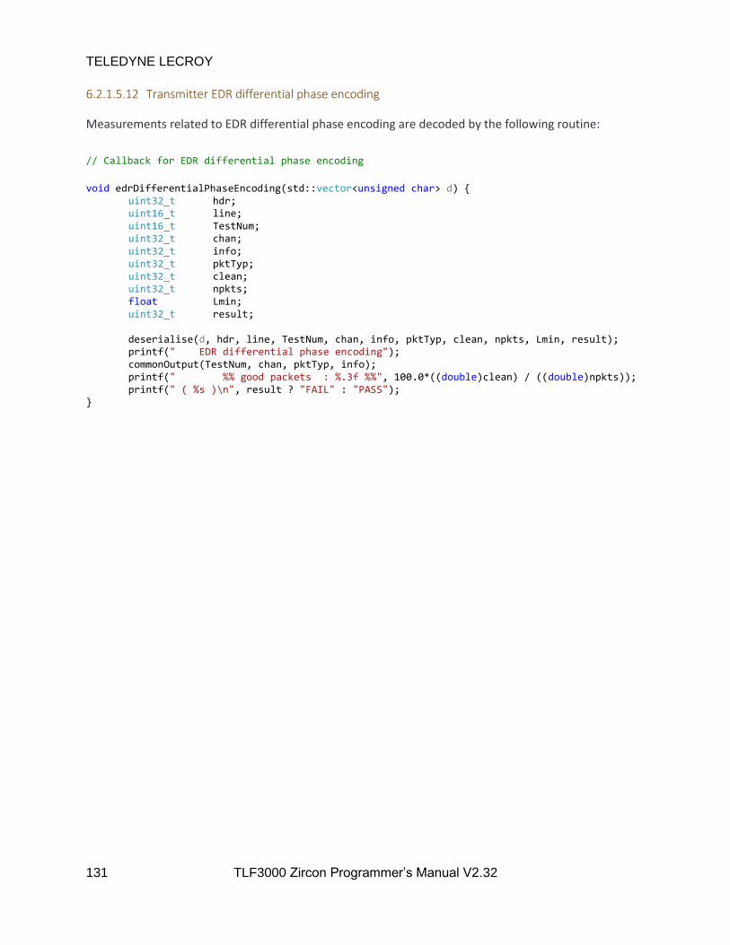
TELEDYNE LECROY
131 TLF3000 Zircon Programmer’s Manual V2.32
6.2.1.5.12 Transmitter EDR differential phase encoding
Measurements related to EDR differential phase encoding are decoded by the following routine:
// Callback for EDR differential phase encoding
void edrDifferentialPhaseEncoding(std::vector<unsigned char> d) uint32_t hdr; uint16_t line; uint16_t TestNum; uint32_t chan; uint32_t info; uint32_t pktTyp; uint32_t clean; uint32_t npkts; float Lmin; uint32_t result; deserialise(d, hdr, line, TestNum, chan, info, pktTyp, clean, npkts, Lmin, result); printf(" EDR differential phase encoding"); commonOutput(TestNum, chan, pktTyp, info); printf(" %% good packets : %.3f %%", 100.0*((double)clean) / ((double)npkts)); printf(" ( %s )\n", result ? "FAIL" : "PASS");

TELEDYNE LECROY
132 TLF3000 Zircon Programmer’s Manual V2.32
6.2.1.5.13 Transmitter EDR in-band spurious emissions
Measurements related to EDR in-band spurious emissions are decoded by the following routine. Two
spectra are returned. The first contains the ACP measurements every 1MHz from 2395MHz to 2485MHz
inclusive. The second contains the 100kHz RBW measurements which were used to generate the 1MHz
resolution results. These measurements are from 2394.550MHz to 2485.450MHz in 100kHz steps.
// Callback for EDR in-band spurious emissions
void edrInBandSpuriousEmissions(std::vector<unsigned char> d, uint16_t SubTest) uint32_t hdr; uint16_t line; uint16_t TestNum; uint32_t chan; uint32_t info; uint32_t pktTyp; float Pmin; float Pmax; float Lmin; float Lmax; uint32_t result; float spectrum[91]; static uint16_t oldSubTest = 99; if (SubTest == 1) deserialise(d, hdr, line, TestNum, chan, info, pktTyp, Pmin, Pmax, Lmin, Lmax, result); printf(" | M - N | = 2 : %.1f dBm", Pmax); printf(" ( %s )\n", (result & 1) ? "FAIL" : "PASS"); else if (SubTest == 2) deserialise(d, hdr, line, TestNum, chan, info, pktTyp, Pmin, Pmax, Lmin, Lmax, result); printf(" | M - N | >= 3 : %.1f dBm", Pmax); printf(" ( %s )\n", (result & 1) ? "FAIL" : "PASS"); else if (SubTest == 3) deserialise(d, hdr, line, TestNum, chan, info, pktTyp, Pmin, Pmax, Lmin, Lmax, result); if (oldSubTest != 4) printf(" EDR in-band spurious emissions"); commonOutput(TestNum, chan, pktTyp, info); printf(" # exceptions : %.0f", Pmax); printf(" ( %s )\n", (result & 1) ? "FAIL" : "PASS"); else if (SubTest == 4) deserialise(d, hdr, line, TestNum, chan, info, pktTyp, Pmin, Pmax, Lmin, Lmax, result); printf(" EDR in-band spurious emissions"); commonOutput(TestNum, chan, pktTyp, info); printf(" Max exception : %.1f dBm", Pmax); printf(" ( %s )\n", (result & 1) ? "FAIL" : "PASS"); else if (SubTest == 5) deserialise(d, hdr, line, TestNum, chan, info, pktTyp, spectrum);

TELEDYNE LECROY
133 TLF3000 Zircon Programmer’s Manual V2.32
else if (SubTest == 0) deserialise(d, hdr, line, TestNum, chan, info, pktTyp, Pmin, Pmax, Lmin, Lmax, result); printf(" PTXref - PTX : %.1f dBm", Pmax); printf(" ( %s )\n", (result & 1) ? "FAIL" : "PASS"); else printf("Unknown sub test %d\n", SubTest); oldSubTest = SubTest;

TELEDYNE LECROY
134 TLF3000 Zircon Programmer’s Manual V2.32
6.2.1.5.14 Transmitter enhanced power control
Measurements related to transmitter enhanced power control are decoded by the following routine.
// Callback for tx enhanced power control
void enhancedPowerControl(std::vector<unsigned char> d, uint16_t SubTest) uint32_t hdr; uint16_t line; uint16_t TestNum; uint32_t chan; uint32_t info; uint32_t pktTyp; float Pmin; float Pmax; float Lmin; float Lmax; uint32_t result; static uint32_t oldChan = 99; static uint32_t oldInfo = 0; static uint32_t oldPktTyp = 0; deserialise(d, hdr, line, TestNum, chan, info, pktTyp, Pmin, Pmax, Lmin, Lmax, result); if ((chan != oldChan) || (oldInfo != info) || (oldPktTyp != pktTyp)) printf(" Enhanced power control"); commonOutput(TestNum, chan, pktTyp, info); oldChan = chan; oldInfo = info; oldPktTyp = pktTyp; if (SubTest == 0) printf(" Power step down : %.1f dBm", Pmin); printf(" ( %s )\n", (result & 1) ? "FAIL" : "PASS"); else if (SubTest == 1) printf(" Minimum power : %.1f dBm", Pmin); printf(" ( %s )\n", (result & 1) ? "FAIL" : "PASS"); else if (SubTest == 8) printf(" Power step up : %.1f dBm", Pmin); printf(" ( %s )\n", (result & 1) ? "FAIL" : "PASS"); else if (SubTest == 4) printf(" GFSK step down : %.1f dBm", Pmin); printf(" ( %s )\n", (result & 1) ? "FAIL" : "PASS"); else if (SubTest == 12) printf(" GFSK step up : %.1f dBm", Pmin); printf(" ( %s )\n", (result & 1) ? "FAIL" : "PASS"); else if (SubTest == 3) printf(" Start/End diff : %.1f dBm", Pmin); printf(" ( %s )\n", (result & 1) ? "FAIL" : "PASS"); else printf("Unknown sub test %d\n", SubTest);
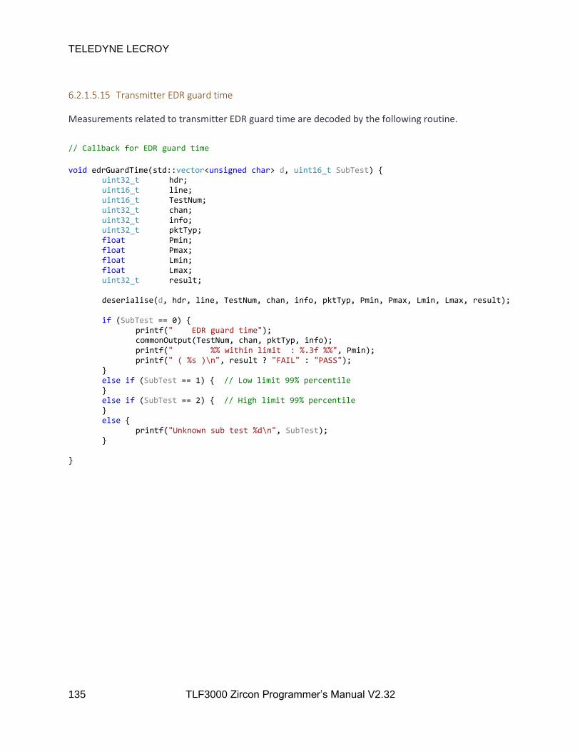
TELEDYNE LECROY
135 TLF3000 Zircon Programmer’s Manual V2.32
6.2.1.5.15 Transmitter EDR guard time
Measurements related to transmitter EDR guard time are decoded by the following routine.
// Callback for EDR guard time
void edrGuardTime(std::vector<unsigned char> d, uint16_t SubTest) uint32_t hdr; uint16_t line; uint16_t TestNum; uint32_t chan; uint32_t info; uint32_t pktTyp; float Pmin; float Pmax; float Lmin; float Lmax; uint32_t result; deserialise(d, hdr, line, TestNum, chan, info, pktTyp, Pmin, Pmax, Lmin, Lmax, result); if (SubTest == 0) printf(" EDR guard time"); commonOutput(TestNum, chan, pktTyp, info); printf(" %% within limit : %.3f %%", Pmin); printf(" ( %s )\n", result ? "FAIL" : "PASS"); else if (SubTest == 1) // Low limit 99% percentile else if (SubTest == 2) // High limit 99% percentile else printf("Unknown sub test %d\n", SubTest);
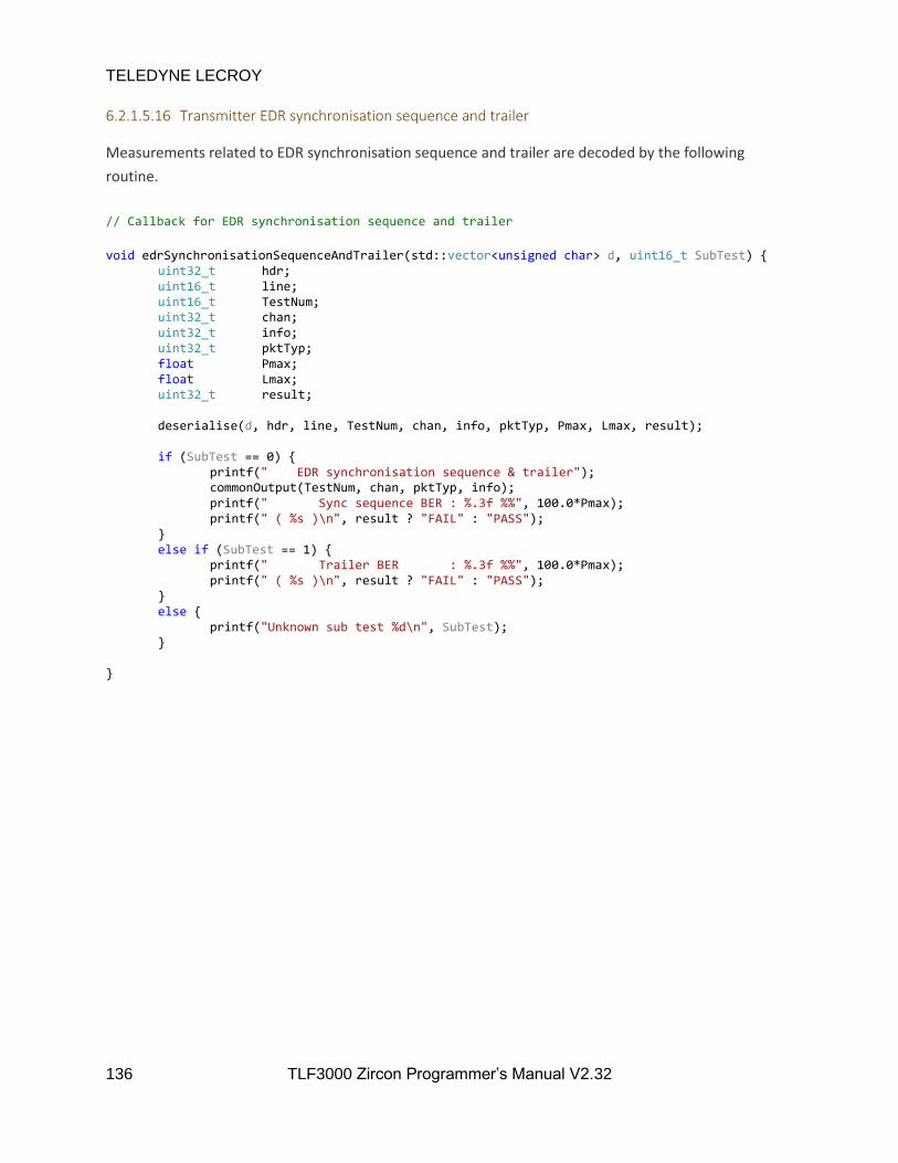
TELEDYNE LECROY
136 TLF3000 Zircon Programmer’s Manual V2.32
6.2.1.5.16 Transmitter EDR synchronisation sequence and trailer
Measurements related to EDR synchronisation sequence and trailer are decoded by the following
routine.
// Callback for EDR synchronisation sequence and trailer
void edrSynchronisationSequenceAndTrailer(std::vector<unsigned char> d, uint16_t SubTest) uint32_t hdr; uint16_t line; uint16_t TestNum; uint32_t chan; uint32_t info; uint32_t pktTyp; float Pmax; float Lmax; uint32_t result; deserialise(d, hdr, line, TestNum, chan, info, pktTyp, Pmax, Lmax, result); if (SubTest == 0) printf(" EDR synchronisation sequence & trailer"); commonOutput(TestNum, chan, pktTyp, info); printf(" Sync sequence BER : %.3f %%", 100.0*Pmax); printf(" ( %s )\n", result ? "FAIL" : "PASS"); else if (SubTest == 1) printf(" Trailer BER : %.3f %%", 100.0*Pmax); printf(" ( %s )\n", result ? "FAIL" : "PASS"); else printf("Unknown sub test %d\n", SubTest);

TELEDYNE LECROY
137 TLF3000 Zircon Programmer’s Manual V2.32
6.2.1.6 Receiver test results
Receiver test results are directed through a single routine called by the main asynchronous callback
handler. The nature of the receiver test is determined and an appropriate routine for handling the
asynchronous data is called.
void RxTest(std::vector<unsigned char> d) uint32_t hdr; uint16_t line; uint16_t TestNum; uint16_t SubTest; deserialise(d, hdr, line, TestNum); SubTest = TestNum >> 12; TestNum = (TestNum >> 4) & 0xFF; switch (TestNum) case 1: sensitivity(d,"Sensitivity - single slot"); break; case 2: sensitivity(d, "Sensitivity - multi slot"); break; case 3: ciPerformance(d, SubTest, "C/I Performance"); break; case 4: blocking(d, SubTest); break; case 5: intermodulation(d); break; case 6: sensitivity(d, "Maximum input level"); break; case 7: sensitivity(d, "EDR sensitivity"); break; case 8: sensitivity(d, "EDR BER floor performance"); break; case 9: ciPerformance(d, SubTest, "EDR C/I Performance"); break; case 10: sensitivity(d, "EDR maximum input level"); break; default: break;

TELEDYNE LECROY
138 TLF3000 Zircon Programmer’s Manual V2.32
6.2.1.6.1 Receiver sensitivity results
Measurements related to receiver sensitivity are decoded by the following routine:
// Callback for rx sensitivity and maximum input messages void sensitivity(std::vector<unsigned char> d, const char *title) uint32_t hdr; uint16_t line; uint16_t TestNum; uint32_t chan; uint32_t info; uint32_t pktTyp; int32_t wPwr; uint32_t nBits; uint32_t nErrs; uint32_t num1; float lim1; uint32_t num2; float lim2; uint32_t early; uint32_t result; static uint32_t oldChan = 99; static uint32_t oldInfo = 0; static uint32_t oldPktTyp = 0; deserialise(d, hdr, line, TestNum, chan, info, pktTyp, wPwr, nBits, nErrs, num1, lim1, num2, lim2, early, result); if ((((TestNum >> 4) & 0xFF) != lastTestNum) || (chan != oldChan) || (oldInfo != info) || (oldPktTyp != pktTyp)) printf(" %s", title); commonOutput(TestNum, chan, pktTyp, info); oldChan = chan; oldInfo = info; oldPktTyp = pktTyp; printf(" Wanted power %.1f dBm\n", 0.1f*wPwr); printf(" BER : %.3f %%", 100.0*((double)nErrs) / ((double)nBits)); if (early) printf(" (early exit) "); printf(" ( %s )\n", result ? "FAIL" : "PASS");
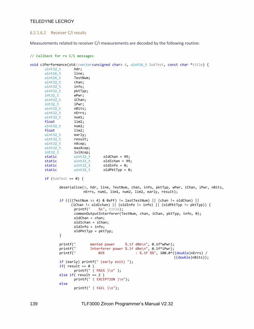
TELEDYNE LECROY
139 TLF3000 Zircon Programmer’s Manual V2.32
6.2.1.6.2 Receiver C/I results
Measurements related to receiver C/I measurements are decoded by the following routine:
// Callback for rx C/I messages void ciPerformance(std::vector<unsigned char> d, uint16_t SubTest, const char *title) uint32_t hdr; uint16_t line; uint16_t TestNum; uint32_t chan; uint32_t info; uint32_t pktTyp; int32_t wPwr; uint32_t iChan; int32_t iPwr; uint32_t nBits; uint32_t nErrs; uint32_t num1; float lim1; uint32_t num2; float lim2; uint32_t early; uint32_t result; uint32_t nXcep; uint32_t maxXcep; int32_t lvlXcep; static uint32_t oldChan = 99; static uint32_t oldIchan = 99; static uint32_t oldInfo = 0; static uint32_t oldPktTyp = 0; if (SubTest == 0) deserialise(d, hdr, line, TestNum, chan, info, pktTyp, wPwr, iChan, iPwr, nBits, nErrs, num1, lim1, num2, lim2, early, result); if ((((TestNum >> 4) & 0xFF) != lastTestNum) || (chan != oldChan) || (iChan != oldIchan) || (oldInfo != info) || (oldPktTyp != pktTyp)) printf(" %s", title); commonOutputInterferer(TestNum, chan, iChan, pktTyp, info, 0); oldChan = chan; oldIchan = iChan; oldInfo = info; oldPktTyp = pktTyp; printf(" Wanted power %.1f dBm\n", 0.1f*wPwr); printf(" Interferer power %.1f dBm\n", 0.1f*iPwr); printf(" BER : %.3f %%", 100.0*((double)nErrs) / ((double)nBits)); if (early) printf(" (early exit) "); if( result == 0 ) printf(" ( PASS )\n" ); else if( result == 2 ) printf(" ( EXCEPTION )\n"); else printf(" ( FAIL )\n");
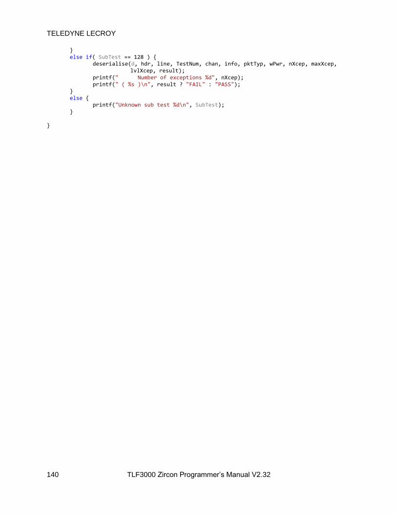
TELEDYNE LECROY
140 TLF3000 Zircon Programmer’s Manual V2.32
else if( SubTest == 128 ) deserialise(d, hdr, line, TestNum, chan, info, pktTyp, wPwr, nXcep, maxXcep, lvlXcep, result); printf(" Number of exceptions %d", nXcep); printf(" ( %s )\n", result ? "FAIL" : "PASS"); else printf("Unknown sub test %d\n", SubTest);
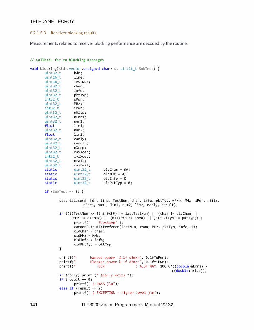
TELEDYNE LECROY
141 TLF3000 Zircon Programmer’s Manual V2.32
6.2.1.6.3 Receiver blocking results
Measurements related to receiver blocking performance are decoded by the routine:
// Callback for rx blocking messages void blocking(std::vector<unsigned char> d, uint16_t SubTest) uint32_t hdr; uint16_t line; uint16_t TestNum; uint32_t chan; uint32_t info; uint32_t pktTyp; int32_t wPwr; uint32_t MHz; int32_t iPwr; uint32_t nBits; uint32_t nErrs; uint32_t num1; float lim1; uint32_t num2; float lim2; uint32_t early; uint32_t result; uint32_t nXcep; uint32_t maxXcep; int32_t lvlXcep; uint32_t nFail; uint32_t maxFail; static uint32_t oldChan = 99; static uint32_t oldMHz = 0; static uint32_t oldInfo = 0; static uint32_t oldPktTyp = 0; if (SubTest == 0) deserialise(d, hdr, line, TestNum, chan, info, pktTyp, wPwr, MHz, iPwr, nBits, nErrs, num1, lim1, num2, lim2, early, result); if ((((TestNum >> 4) & 0xFF) != lastTestNum) || (chan != oldChan) || (MHz != oldMHz) || (oldInfo != info) || (oldPktTyp != pktTyp)) printf(" Blocking" ); commonOutputInterferer(TestNum, chan, MHz, pktTyp, info, 1); oldChan = chan; oldMHz = MHz; oldInfo = info; oldPktTyp = pktTyp; printf(" Wanted power %.1f dBm\n", 0.1f*wPwr); printf(" Blocker power %.1f dBm\n", 0.1f*iPwr); printf(" BER : %.3f %%", 100.0*((double)nErrs) / ((double)nBits)); if (early) printf(" (early exit) "); if (result == 0) printf(" ( PASS )\n"); else if (result == 2) printf(" ( EXCEPTION - higher level )\n");
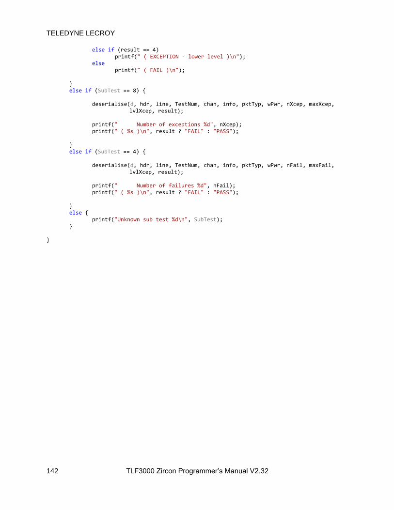
TELEDYNE LECROY
142 TLF3000 Zircon Programmer’s Manual V2.32
else if (result == 4) printf(" ( EXCEPTION - lower level )\n"); else printf(" ( FAIL )\n"); else if (SubTest == 8) deserialise(d, hdr, line, TestNum, chan, info, pktTyp, wPwr, nXcep, maxXcep, lvlXcep, result); printf(" Number of exceptions %d", nXcep); printf(" ( %s )\n", result ? "FAIL" : "PASS"); else if (SubTest == 4) deserialise(d, hdr, line, TestNum, chan, info, pktTyp, wPwr, nFail, maxFail, lvlXcep, result); printf(" Number of failures %d", nFail); printf(" ( %s )\n", result ? "FAIL" : "PASS"); else printf("Unknown sub test %d\n", SubTest);

TELEDYNE LECROY
143 TLF3000 Zircon Programmer’s Manual V2.32
6.2.1.6.4 Receiver intermodulation results
Measurements related to the receiver intermodulation performance are handled by the following
routine:
// Callback for rx intermodulation messages void intermodulation(std::vector<unsigned char> d) uint32_t hdr; uint16_t line; uint16_t TestNum; uint32_t chan; uint32_t info; uint32_t pktTyp; int32_t wPwr; uint32_t n; int32_t iPwr; uint32_t nBits; uint32_t nErrs; uint32_t num1; float lim1; uint32_t num2; float lim2; uint32_t early; uint32_t result; static uint32_t oldChan = 99; static uint32_t oldN = 99; static uint32_t oldInfo = 0; static uint32_t oldPktTyp = 0; deserialise(d, hdr, line, TestNum, chan, info, pktTyp, wPwr, n, iPwr, nBits, nErrs, num1, lim1, num2, lim2, early, result); if ((((TestNum >> 4) & 0xFF) != lastTestNum) || (chan != oldChan) || (n != oldN) || (oldInfo != info) || (oldPktTyp != pktTyp)) printf(" Intermodulation"); commonOutputInterferer(TestNum, chan, n, pktTyp, info, 2); oldChan = chan; oldN = n; oldInfo = info; oldPktTyp = pktTyp; printf(" Wanted power %.1f dBm\n", 0.1f*wPwr); printf(" Interferer power %.1f dBm\n", 0.1f*iPwr); printf(" BER : %.3f %%", 100.0*((double)nErrs) / ((double)nBits)); if (early) printf(" (early exit) "); printf(" ( %s )\n", result ? "FAIL" : "PASS");

TELEDYNE LECROY
144 TLF3000 Zircon Programmer’s Manual V2.32
6.2.2 Programming the signal generator
This example code demonstrates how to program the various signal generator sources and then turn on
the signal generator output.
The sequence of operations is as follows:
1. A connection is made to the wanted TLF3000 unit using the connection code described in
Connecting to the TLF3000
2. A callback for asynchronous messages is registered using the code described in Handling
asynchronous data
3. The operating mode is set to signal generator mode using zircon_setMode
4. The cable loss is set by calling zircon_setCableLosses
5. The wanted signal is programmed using zircon_progWanted. At this stage there is no output
from the signal generator since it has not been started.
6. An interferer signal is programmed using zircon_progInterferer.
7. An in-band CW blocker is programmed using zircon_progCW.
8. A second in-band CW blocker is programmed using zircon_progCW.
9. An AWGN source is programmed using zircon_progAWGN.
10. An out–of-band CW blocker is programmed using zircon_progOutOfBandCW .
11. The signal generator is started by calling zircon_startSigGen. It is only at this point that the signal
generator starts outputting power.
12. Execution is paused until the asynchronous callback for all programmed packets has been called.
13. The signal generator is stopped using zircon_stopSigGen. This does not affect the programming
which has previously been performed.

HANDLE sem; // Cable loss definition #define nLoss (3) float frqs[nLoss] = 2402.0f , 2441.0f , 2480.0f ; float loss[nLoss] = 1.0f , 1.1f , 1.2f ; int main() DWORD err; sem = CreateSemaphoreA(NULL, 0, 1, "Done"); // ---------------- // CONNNECT TO UNIT // ---------------- zircon_search_result_t* results; while (true) int N; zircon_search(&results, &N); for (int i = 0; i < N; i++) printf("Found: %d\n", results[i].serial_number); if (N) // This simply connects to the first unit which is found printf("Connecting\n"); zircon_connect(results[0].handle); break; std::this_thread::sleep_for(500ms); // ------------- // GENERAL SETUP // ------------- // Register callback for asynch data channel zircon_set_data_callback((zircon_data_callback_t)&dataCallback); // Enter signal generator mode if (zircon_setMode(1) != ZIRCON_NO_ERROR) getError();

TELEDYNE LECROY
146 TLF3000 Zircon Programmer’s Manual V2.32
// Set cable loss if (zircon_setCableLosses(nLoss, frqs, loss) != ZIRCON_NO_ERROR) getError(); // --------------------- // PROGRAM WANTED SIGNAL // --------------------- // Distortion table for wanted signal - set numDistort to zero for no distortions // carrier offset in kHZ // modulation index x 10000 // drift magnitude in kHz // drift rate in Hz // symbol timing error in ppm uint32_t numDistort = 2; int16_t distortions[] = 0, 3200, 0, 0, 0, 50, 3200, 0, 0, 0 ; // Program the wanted signal // Arg1 : True = on, False = off // Arg2 : RF channel, 0 -> 78 // Arg3 : Amplitude in dBm // Arg4 : phy, 0 = BR, 1 = 2 - EDR, 2 = 3 - EDR // Arg5 : UAP - 8bits // Arg6 : True = whiten, False = do not whiten // Arg7 : Central clock, LSB used for whitening, ignored if whitening disabled // Arg8 : LAP - 24bits // Arg9 : Header contents without HEC - 10bits, but the packet type bits are ignored and set on the basis of Arg11 // Arg10 : Payload header - numbers of bits dependent on packet type, those bits which denote the number of octets are // ignored and are set on the basis of Arg21 // Arg11 : Packet type // 0 = ID // 1 = NULL // 2 = POLL // 3 = FHS // 4 = DM1 // 5 = DH1 // 6 = DM3 // 7 = DH3 // 8 = DM5 // 9 = DH5 // 10 = AUX1 // 11 = 2 - DH1

TELEDYNE LECROY
147 TLF3000 Zircon Programmer’s Manual V2.32
// 12 = 2 - DH3 // 13 = 2 - DH5 // 14 = 3 - DH1 // 15 = 3 - DH3 // 16 = 3 - DH5 // 17 = HV1 // 18 = HV2 // 19 = HV3 // 20 = DV // 21 = EV3 // 22 = EV4 // 23 = EV5 // 24 = 2 - EV3 // 25 = 2 - EV5 // 26 = 3 - EV3 // 27 = 3 - EV5 // Arg12: Payload type // 0 = PRBS9 // 1 = PRBS11 // 2 = PRBS15 // 3 = PRBS20 // 4 = PRBS23 // 5 = PRBS29 // 6 = PRBS31 // 7 = 00001111 // 8 = 01010101 // 9 = 11111111 // 10 = 00000000 // 11 = 11110000 // 12 = 10101010 // Arg13: adjustment to guard interval in us // Arg14 : relative amplitude of EDR re GFSK in dB // Arg15 : number of packets to send, 0 = > infinite // Arg16: interval between packets in us // Arg17 : ramp time in us // Arg18 : length of unmodulated carrier prior to preamble in us // Arg19 : length of unmodulated carrier after CRC and prior to ramp down in us // Arg20 : number of sets of distortions - can be zero // Arg21 : number of octets in payload // Arg22 : array containing distortions printf("Program wanted signal\n"); if (zircon_progWanted(true, 10, -20, 2, 0x7D, false, 0x00, 0xE78F12, 0x00, 0x00, 16, 7, 0.0, -2.0, 10000, 6 * 625, 2.0, 2.0, 2.0, numDistort, 1021, distortions) != ZIRCON_NO_ERROR) getError();

TELEDYNE LECROY
148 TLF3000 Zircon Programmer’s Manual V2.32
// ------------------ // PROGRAM INTERFERER // ------------------ // Program interferer signal // Arg1 : True = on, False = off // Arg2 : True = continuous transmission, False = packetised transmission // Arg3 : Amplitude in dBm // Arg4 : phy, 0 = BR, 1 = 2 - EDR, 2 = 3 - EDR // Arg5 : Number of octets in payload for packetised transmission, ignored otherwise // Arg6 : Frequency of transmission in MHz // Arg7 : Period between packets in us for packetised transmission, ignored otherwise printf("Program interferer\n"); if (zircon_progInterferer(true, false, -15, 0, 27, 2460, 2 * 625) != ZIRCON_NO_ERROR) getError(); // --------------------- // PROGRAM 1st CW SOURCE // --------------------- // Program first CW // Arg1 : Number of CW interferer to program // Arg2 : True = on, False = off // Arg3 : Amplitude in dBm // Arg4 : Frequency in Hz printf("Program first CW signal\n"); if (zircon_progCW(0, true, -40, 2451000000) != ZIRCON_NO_ERROR) getError(); // --------------------- // PROGRAM 2nd CW SOURCE // --------------------- // Program second CW // Arg1 : Number of CW interferer to program // Arg2 : True = on, False = off // Arg3 : Amplitude in dBm // Arg4 : Frequency in Hz printf("Program first CW signal\n"); if (zircon_progCW(1, true, -40, 2421000000) != ZIRCON_NO_ERROR) getError(); // ------------ // PROGRAM AWGN // ------------
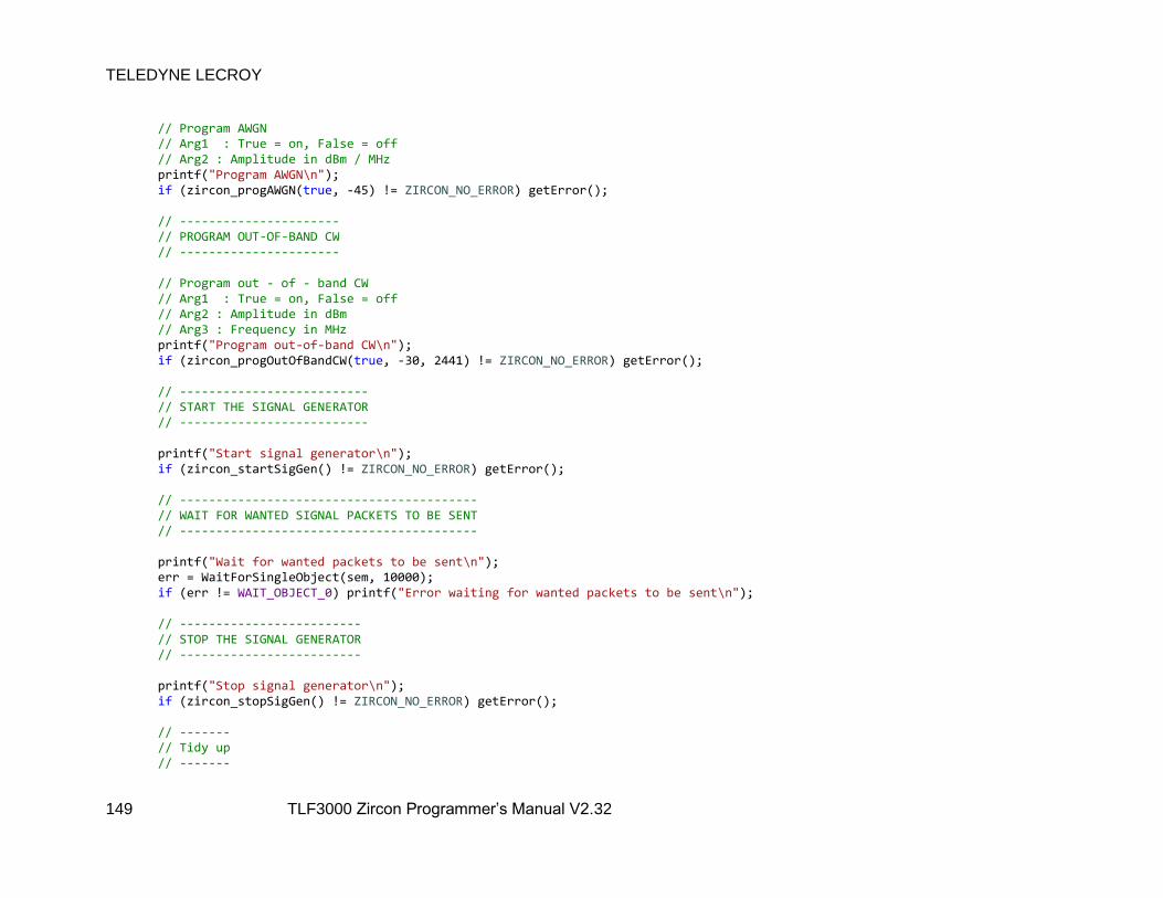
TELEDYNE LECROY
149 TLF3000 Zircon Programmer’s Manual V2.32
// Program AWGN // Arg1 : True = on, False = off // Arg2 : Amplitude in dBm / MHz printf("Program AWGN\n"); if (zircon_progAWGN(true, -45) != ZIRCON_NO_ERROR) getError(); // ---------------------- // PROGRAM OUT-OF-BAND CW // ---------------------- // Program out - of - band CW // Arg1 : True = on, False = off // Arg2 : Amplitude in dBm // Arg3 : Frequency in MHz printf("Program out-of-band CW\n"); if (zircon_progOutOfBandCW(true, -30, 2441) != ZIRCON_NO_ERROR) getError(); // -------------------------- // START THE SIGNAL GENERATOR // -------------------------- printf("Start signal generator\n"); if (zircon_startSigGen() != ZIRCON_NO_ERROR) getError(); // ----------------------------------------- // WAIT FOR WANTED SIGNAL PACKETS TO BE SENT // ----------------------------------------- printf("Wait for wanted packets to be sent\n"); err = WaitForSingleObject(sem, 10000); if (err != WAIT_OBJECT_0) printf("Error waiting for wanted packets to be sent\n"); // ------------------------- // STOP THE SIGNAL GENERATOR // ------------------------- printf("Stop signal generator\n"); if (zircon_stopSigGen() != ZIRCON_NO_ERROR) getError(); // ------- // Tidy up // -------
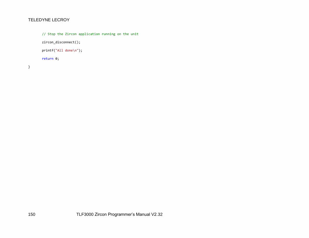
TELEDYNE LECROY
150 TLF3000 Zircon Programmer’s Manual V2.32
// Stop the Zircon application running on the unit zircon_disconnect(); printf("All done\n"); return 0;

6.2.2.1 Completion of transmission of wanted signal
When the transmission of the wanted signal is complete, an asynchronous callback is made. This is
handled by the following routine:
void running() ReleaseSemaphore(sem, 1, NULL);
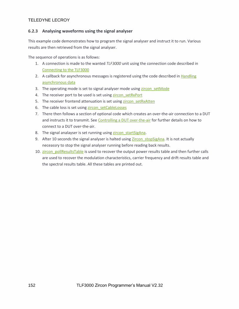
TELEDYNE LECROY
152 TLF3000 Zircon Programmer’s Manual V2.32
6.2.3 Analysing waveforms using the signal analyser
This example code demonstrates how to program the signal analyser and instruct it to run. Various
results are then retrieved from the signal analyser.
The sequence of operations is as follows:
1. A connection is made to the wanted TLF3000 unit using the connection code described in
Connecting to the TLF3000
2. A callback for asynchronous messages is registered using the code described in Handling
asynchronous data
3. The operating mode is set to signal analyser mode using zircon_setMode
4. The receiver port to be used is set using zircon_setRxPort
5. The receiver frontend attenuation is set using zircon_setRxAtten
6. The cable loss is set using zircon_setCableLosses
7. There then follows a section of optional code which creates an over-the-air connection to a DUT
and instructs it to transmit. See Controlling a DUT over-the-air for further details on how to
connect to a DUT over-the-air.
8. The signal analayser is set running using zircon_startSigAna.
9. After 10 seconds the signal analyser is halted using Zircon_stopSigAna. It is not actually
neceassry to stop the signal analyser running before reading back results.
10. zircon_pollResultsTable is used to recover the output power results table and then further calls
are used to recover the modulation characteristics, carrier frequency and drift results table and
the spectral results table. All these tables are printed out.

#define maxRes (200) HANDLE sem; uint64_t DUTaddr; // Cable loss definition #define nLoss (3) float frqs[nLoss] = 2402.0f , 2441.0f , 2480.0f ; float loss[nLoss] = 1.0f , 1.1f , 1.2f ; // ----------------------------------- // Routine for printing results tables // ----------------------------------- const char *PowerHeadingsBR[] = "Pavg", "Pk-Pavg" ; const char *PowerHeadingsEDR[] = "Pavg", "EDR re GFSK", "Guard- 99%", "Guard+ 99%", "Guard > 4.6", "Guard < 5.4" ; const char *ModulationHeadingsBR[] = "DF1max", "DF1avg", "DF2max", "DF2avg", "DF2avg/DF1avg", "DF2max 99.9%", "DF2max > 115" ; const char *ModulationHeadingsEDR[] = "RMS DEVM", "PK DEVM", "DEVM <= 30%", "DEVM 99%" ;
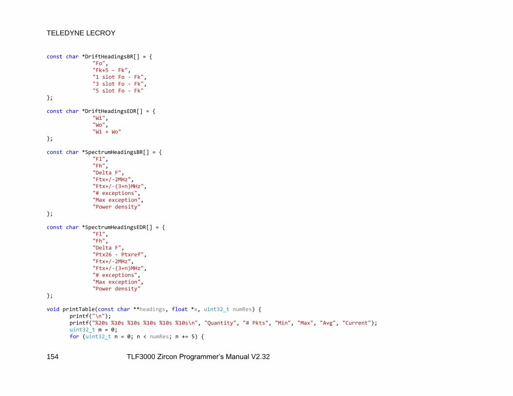
TELEDYNE LECROY
154 TLF3000 Zircon Programmer’s Manual V2.32
const char *DriftHeadingsBR[] = "Fo", "Fk+5 - Fk", "1 slot Fo - Fk", "3 slot Fo - Fk", "5 slot Fo - Fk" ; const char *DriftHeadingsEDR[] = "Wi", "Wo", "Wi + Wo" ; const char *SpectrumHeadingsBR[] = "Fl", "Fh", "Delta F", "Ftx+/-2MHz", "Ftx+/-(3+n)MHz", "# exceptions", "Max exception", "Power density" ; const char *SpectrumHeadingsEDR[] = "Fl", "Fh", "Delta F", "Ptx26 - Ptxref", "Ftx+/-2MHz", "Ftx+/-(3+n)MHz", "# exceptions", "Max exception", "Power density" ; void printTable(const char **headings, float *x, uint32_t numRes) printf("\n"); printf("%20s %10s %10s %10s %10s %10s\n", "Quantity", "# Pkts", "Min", "Max", "Avg", "Current"); uint32_t m = 0; for (uint32_t n = 0; n < numRes; n += 5)

TELEDYNE LECROY
155 TLF3000 Zircon Programmer’s Manual V2.32
printf("%20s ", headings[m]); if (isnan(x[n])) x[n] = 0; printf("%10d %10.1f %10.1f %10.1f %10.1f\n", x[n], x[n + 1], x[n + 2], x[n + 3], x[n + 4]); m++; printf("\n"); int main() float res[maxRes]; uint32_t numRes; DWORD err; sem = CreateSemaphoreA(NULL, 0, 1, "Done"); // ---------------- // CONNNECT TO UNIT // ---------------- zircon_search_result_t* results; while (true) int N; zircon_search(&results, &N); for (int i = 0; i < N; i++) printf("Found: %d\n", results[i].serial_number); if (N) // This simply connects to the first unit which is found printf("Connecting\n"); zircon_connect(results[0].handle); break; std::this_thread::sleep_for(500ms); // ------------- // GENERAL SETUP // ------------- // Register callback for asynch data channel zircon_set_data_callback((zircon_data_callback_t)&dataCallback);

TELEDYNE LECROY
156 TLF3000 Zircon Programmer’s Manual V2.32
// Enter signal anayser mode if (zircon_setMode(2) != ZIRCON_NO_ERROR) getError(); // Set rx frontend attenuation in units of 0.5dB if (zircon_setRxAtten(0) != ZIRCON_NO_ERROR) getError(); // Set the rx port to be tx / rx if (zircon_setRxPort(1) != ZIRCON_NO_ERROR) getError(); // Set cable loss if (zircon_setCableLosses(nLoss, frqs, loss) != ZIRCON_NO_ERROR) getError(); // ------------------------------------------------------------------------------------------------ // The example code connects to a DUT to provide the signal to be analysed. This is not necessary, // the DUT can be controlled by another application or the signal to be analysed could be // received off-air // ------------------------------------------------------------------------------------------------ // -------------------------------------------------------------------------------- // DO AN INQUIRY TO FIND THE DUT (not required if the DUT address is already known) // -------------------------------------------------------------------------------- DUTaddr = 0; while (!DUTaddr) // Arg1 : Time duration of inquiry in ms // Arg2 : Inquiry power per channel in unit of 0.1 dBm // Arg3 : RSSI threshold for inquiry responses in dBm // Arg4 : Expected number of responses printf("Inquiry\n"); if (zircon_inquiry(10000, -400, -40, 1) != ZIRCON_NO_ERROR) getError(); err = WaitForSingleObject(sem, 11000); if (err != WAIT_OBJECT_0) printf("Error waiting for inquiry to complete\n"); if (!DUTaddr) printf("No DUT found ... press return to try again\n"); getchar();
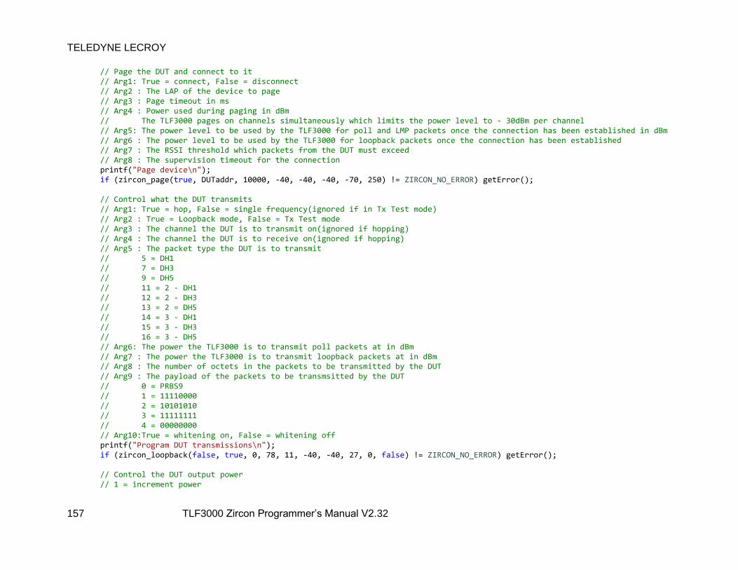
TELEDYNE LECROY
157 TLF3000 Zircon Programmer’s Manual V2.32
// Page the DUT and connect to it // Arg1: True = connect, False = disconnect // Arg2 : The LAP of the device to page // Arg3 : Page timeout in ms // Arg4 : Power used during paging in dBm // The TLF3000 pages on channels simultaneously which limits the power level to - 30dBm per channel // Arg5: The power level to be used by the TLF3000 for poll and LMP packets once the connection has been established in dBm // Arg6 : The power level to be used by the TLF3000 for loopback packets once the connection has been established // Arg7 : The RSSI threshold which packets from the DUT must exceed // Arg8 : The supervision timeout for the connection printf("Page device\n"); if (zircon_page(true, DUTaddr, 10000, -40, -40, -40, -70, 250) != ZIRCON_NO_ERROR) getError(); // Control what the DUT transmits // Arg1: True = hop, False = single frequency(ignored if in Tx Test mode) // Arg2 : True = Loopback mode, False = Tx Test mode // Arg3 : The channel the DUT is to transmit on(ignored if hopping) // Arg4 : The channel the DUT is to receive on(ignored if hopping) // Arg5 : The packet type the DUT is to transmit // 5 = DH1 // 7 = DH3 // 9 = DH5 // 11 = 2 - DH1 // 12 = 2 - DH3 // 13 = 2 = DH5 // 14 = 3 - DH1 // 15 = 3 - DH3 // 16 = 3 - DH5 // Arg6: The power the TLF3000 is to transmit poll packets at in dBm // Arg7 : The power the TLF3000 is to transmit loopback packets at in dBm // Arg8 : The number of octets in the packets to be transmitted by the DUT // Arg9 : The payload of the packets to be transmsitted by the DUT // 0 = PRBS9 // 1 = 11110000 // 2 = 10101010 // 3 = 11111111 // 4 = 00000000 // Arg10:True = whitening on, False = whitening off printf("Program DUT transmissions\n"); if (zircon_loopback(false, true, 0, 78, 11, -40, -40, 27, 0, false) != ZIRCON_NO_ERROR) getError(); // Control the DUT output power // 1 = increment power

TELEDYNE LECROY
158 TLF3000 Zircon Programmer’s Manual V2.32
// 2 = maximum power // 255 = decrement power // 254 = minimum power printf("Set DUT power\n"); if (zircon_pwrControl(2)) getError(); // Change the level of poll packets sent by the TLF3000 printf("Set TLF3000 power\n"); if (zircon_pollPwr(-50) != ZIRCON_NO_ERROR) getError(); // Change the level of loopback packets sent by the TLF3000 (ignored in Tx Test mode) if (zircon_loopPwr(-50) != ZIRCON_NO_ERROR) getError(); // ------------------------------------------------- // START THE SIGNAL ANALYSER NOW DUT IS TRANSMITTING // ------------------------------------------------- // Start the signal analyser // Arg 1 : Supervision timeout in ms, ignored if no DUT is being controlled // Arg 2 : RSSI threshold for packets to be analysed printf("Start signal analyser\n"); if (zircon_startSigAna(250, -70) != ZIRCON_NO_ERROR) getError(); // Wait for the signal analyser to collect data Sleep(10000); // Stop the signal analyser // Signal analyer can be stopped before or after printing results printf("Stop signal analyser\n"); if (zircon_stopSigAna() != ZIRCON_NO_ERROR) getError(); // -------------------- // OUTPUT POWER RESULTS // -------------------- // Poll results table // Arg1: measurement to be retrieved // Arg2 : bit mask for channel filter // bitn = RF channel number n // Arg3: bit mask for phy filter // bit0 = BR // bit1 = 2 - EDR // bit2 = 3 - EDR
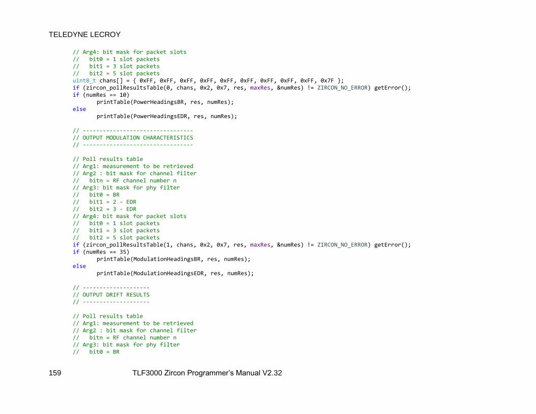
TELEDYNE LECROY
159 TLF3000 Zircon Programmer’s Manual V2.32
// Arg4: bit mask for packet slots // bit0 = 1 slot packets // bit1 = 3 slot packets // bit2 = 5 slot packets uint8_t chans[] = 0xFF, 0xFF, 0xFF, 0xFF, 0xFF, 0xFF, 0xFF, 0xFF, 0xFF, 0x7F ; if (zircon_pollResultsTable(0, chans, 0x2, 0x7, res, maxRes, &numRes) != ZIRCON_NO_ERROR) getError(); if (numRes == 10) printTable(PowerHeadingsBR, res, numRes); else printTable(PowerHeadingsEDR, res, numRes); // --------------------------------- // OUTPUT MODULATION CHARACTERISTICS // --------------------------------- // Poll results table // Arg1: measurement to be retrieved // Arg2 : bit mask for channel filter // bitn = RF channel number n // Arg3: bit mask for phy filter // bit0 = BR // bit1 = 2 - EDR // bit2 = 3 - EDR // Arg4: bit mask for packet slots // bit0 = 1 slot packets // bit1 = 3 slot packets // bit2 = 5 slot packets if (zircon_pollResultsTable(1, chans, 0x2, 0x7, res, maxRes, &numRes) != ZIRCON_NO_ERROR) getError(); if (numRes == 35) printTable(ModulationHeadingsBR, res, numRes); else printTable(ModulationHeadingsEDR, res, numRes); // -------------------- // OUTPUT DRIFT RESULTS // -------------------- // Poll results table // Arg1: measurement to be retrieved // Arg2 : bit mask for channel filter // bitn = RF channel number n // Arg3: bit mask for phy filter // bit0 = BR
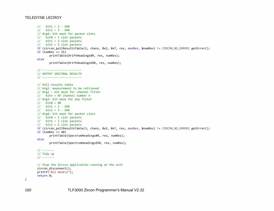
TELEDYNE LECROY
160 TLF3000 Zircon Programmer’s Manual V2.32
// bit1 = 2 - EDR // bit2 = 3 - EDR // Arg4: bit mask for packet slots // bit0 = 1 slot packets // bit1 = 3 slot packets // bit2 = 5 slot packets if (zircon_pollResultsTable(2, chans, 0x2, 0x7, res, maxRes, &numRes) != ZIRCON_NO_ERROR) getError(); if (numRes == 25) printTable(DriftHeadingsBR, res, numRes); else printTable(DriftHeadingsEDR, res, numRes); // ----------------------- // OUTPUT SPECTRAL RESULTS // ----------------------- // Poll results table // Arg1: measurement to be retrieved // Arg2 : bit mask for channel filter // bitn = RF channel number n // Arg3: bit mask for phy filter // bit0 = BR // bit1 = 2 - EDR // bit2 = 3 - EDR // Arg4: bit mask for packet slots // bit0 = 1 slot packets // bit1 = 3 slot packets // bit2 = 5 slot packets if (zircon_pollResultsTable(3, chans, 0x2, 0x7, res, maxRes, &numRes) != ZIRCON_NO_ERROR) getError(); if (numRes == 40) printTable(SpectrumHeadingsBR, res, numRes); else printTable(SpectrumHeadingsEDR, res, numRes); // ------- // Tidy up // ------- // Stop the Zircon application running on the unit zircon_disconnect(); printf("All done\n"); return 0;
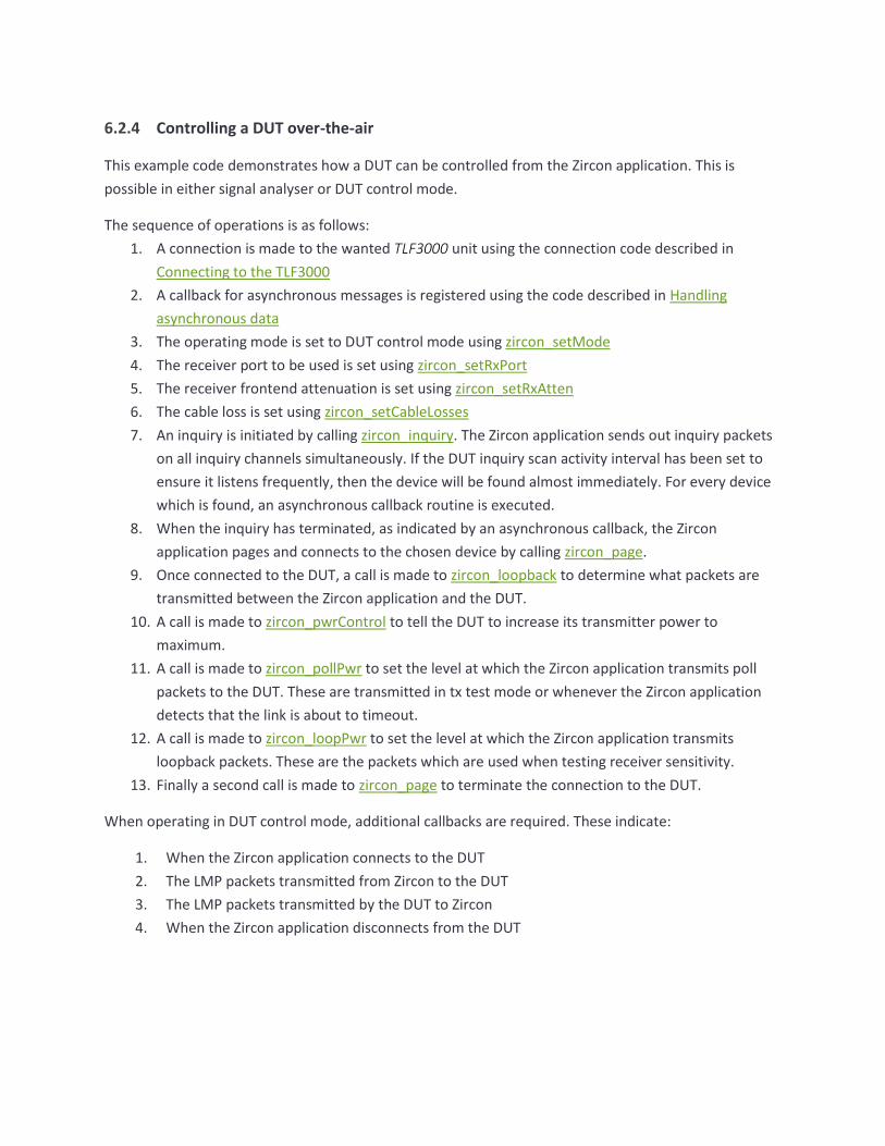
6.2.4 Controlling a DUT over-the-air
This example code demonstrates how a DUT can be controlled from the Zircon application. This is
possible in either signal analyser or DUT control mode.
The sequence of operations is as follows:
1. A connection is made to the wanted TLF3000 unit using the connection code described in
Connecting to the TLF3000
2. A callback for asynchronous messages is registered using the code described in Handling
asynchronous data
3. The operating mode is set to DUT control mode using zircon_setMode
4. The receiver port to be used is set using zircon_setRxPort
5. The receiver frontend attenuation is set using zircon_setRxAtten
6. The cable loss is set using zircon_setCableLosses
7. An inquiry is initiated by calling zircon_inquiry. The Zircon application sends out inquiry packets
on all inquiry channels simultaneously. If the DUT inquiry scan activity interval has been set to
ensure it listens frequently, then the device will be found almost immediately. For every device
which is found, an asynchronous callback routine is executed.
8. When the inquiry has terminated, as indicated by an asynchronous callback, the Zircon
application pages and connects to the chosen device by calling zircon_page.
9. Once connected to the DUT, a call is made to zircon_loopback to determine what packets are
transmitted between the Zircon application and the DUT.
10. A call is made to zircon_pwrControl to tell the DUT to increase its transmitter power to
maximum.
11. A call is made to zircon_pollPwr to set the level at which the Zircon application transmits poll
packets to the DUT. These are transmitted in tx test mode or whenever the Zircon application
detects that the link is about to timeout.
12. A call is made to zircon_loopPwr to set the level at which the Zircon application transmits
loopback packets. These are the packets which are used when testing receiver sensitivity.
13. Finally a second call is made to zircon_page to terminate the connection to the DUT.
When operating in DUT control mode, additional callbacks are required. These indicate:
1. When the Zircon application connects to the DUT
2. The LMP packets transmitted from Zircon to the DUT
3. The LMP packets transmitted by the DUT to Zircon
4. When the Zircon application disconnects from the DUT
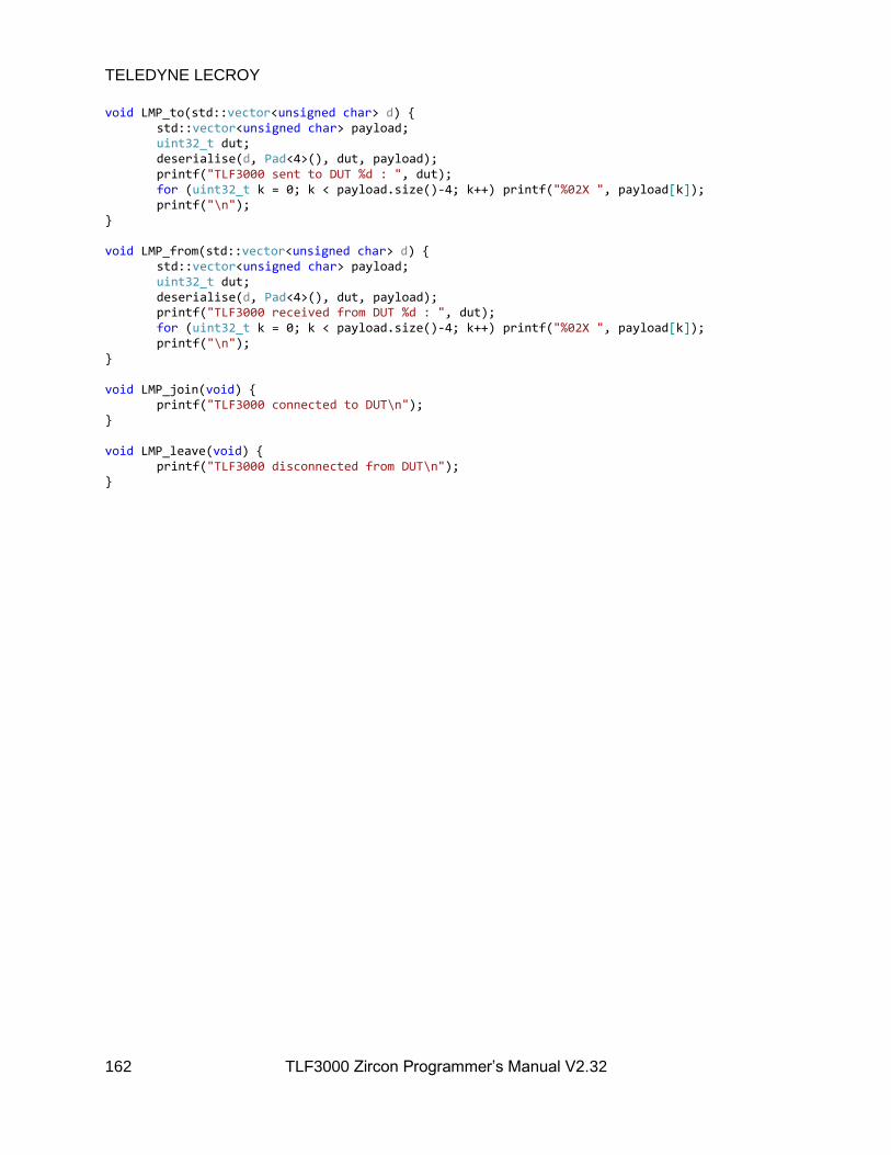
TELEDYNE LECROY
162 TLF3000 Zircon Programmer’s Manual V2.32
void LMP_to(std::vector<unsigned char> d) std::vector<unsigned char> payload; uint32_t dut; deserialise(d, Pad<4>(), dut, payload); printf("TLF3000 sent to DUT %d : ", dut); for (uint32_t k = 0; k < payload.size()-4; k++) printf("%02X ", payload[k]); printf("\n"); void LMP_from(std::vector<unsigned char> d) std::vector<unsigned char> payload; uint32_t dut; deserialise(d, Pad<4>(), dut, payload); printf("TLF3000 received from DUT %d : ", dut); for (uint32_t k = 0; k < payload.size()-4; k++) printf("%02X ", payload[k]); printf("\n"); void LMP_join(void) printf("TLF3000 connected to DUT\n"); void LMP_leave(void) printf("TLF3000 disconnected from DUT\n");

int main() DWORD err; sem = CreateSemaphoreA(NULL, 0, 1, "Done"); // ---------------- // CONNNECT TO UNIT // ---------------- zircon_search_result_t* results; while (true) int N; zircon_search(&results, &N); for (int i = 0; i < N; i++) printf("Found: %d\n", results[i].serial_number); if (N) // This simply connects to the first unit which is found printf("Connecting\n"); zircon_connect(results[0].handle); break; std::this_thread::sleep_for(500ms); // ------------- // GENERAL SETUP // ------------- // Register callback for asynch data channel zircon_set_data_callback((zircon_data_callback_t)&dataCallback); // Enter DUT control mode if (zircon_setMode(5) != ZIRCON_NO_ERROR) getError(); // Set rx frontend attenuation in units of 0.5dB if (zircon_setRxAtten(0) != ZIRCON_NO_ERROR) getError(); // Set the rx port to be tx / rx if (zircon_setRxPort(1) != ZIRCON_NO_ERROR) getError();

TELEDYNE LECROY
164 TLF3000 Zircon Programmer’s Manual V2.32
// Set cable loss if (zircon_setCableLosses(nLoss, frqs, loss) != ZIRCON_NO_ERROR) getError(); // -------------------------------------------------------------------------------- // DO AN INQUIRY TO FIND THE DUT (not required if the DUT address is already known) // -------------------------------------------------------------------------------- DUTaddr = 0; while (!DUTaddr) // Arg1 : Time duration of inquiry in ms // Arg2 : Inquiry power per channel in unit of 0.1 dBm // Arg3 : RSSI threshold for inquiry responses in dBm // Arg4 : Expected number of responses printf("Inquiry\n"); if (zircon_inquiry(10000, -400, -40, 1) != ZIRCON_NO_ERROR) getError(); err = WaitForSingleObject(sem, 11000); if (err != WAIT_OBJECT_0) printf("Error waiting for inquiry to complete\n"); if (!DUTaddr) printf("No DUT found ... press return to try again\n"); getchar(); // Page the DUT and connect to it // Arg1: True = connect, False = disconnect // Arg2 : The LAP of the device to page // Arg3 : Page timeout in ms // Arg4 : Power used during paging in dBm // The TLF3000 pages on channels simultaneously which limits the power level to - 30dBm per channel // Arg5: The power level to be used by the TLF3000 for poll and LMP packets once the connection has been established in dBm // Arg6 : The power level to be used by the TLF3000 for loopback packets once the connection has been established // Arg7 : The RSSI threshold which packets from the DUT must exceed // Arg8 : The supervision timeout for the connection printf("Page device\n"); if (zircon_page(true, DUTaddr, 10000, -40, -40, -40, -70, 250) != ZIRCON_NO_ERROR) getError(); // Control what the DUT transmits // Arg1: True = hop, False = single frequency(ignored if in Tx Test mode)

TELEDYNE LECROY
165 TLF3000 Zircon Programmer’s Manual V2.32
// Arg2 : True = Loopback mode, False = Tx Test mode // Arg3 : The channel the DUT is to transmit on(ignored if hopping) // Arg4 : The channel the DUT is to receive on(ignored if hopping) // Arg5 : The packet type the DUT is to transmit // 5 = DH1 // 7 = DH3 // 9 = DH5 // 11 = 2 - DH1 // 12 = 2 - DH3 // 13 = 2 = DH5 // 14 = 3 - DH1 // 15 = 3 - DH3 // 16 = 3 - DH5 // Arg6: The power the TLF3000 is to transmit poll packets at in dBm // Arg7 : The power the TLF3000 is to transmit loopback packets at in dBm // Arg8 : The number of octets in the packets to be transmitted by the DUT // Arg9 : The payload of the packets to be transmsitted by the DUT // 0 = PRBS9 // 1 = 11110000 // 2 = 10101010 // 3 = 11111111 // 4 = 00000000 // Arg10:True = whitening on, False = whitening off printf("Program DUT transmissions\n"); if (zircon_loopback(false, true, 0, 78, 11, -40, -40, 27, 0, false) != ZIRCON_NO_ERROR) getError(); // Control the DUT output power // 1 = increment power // 2 = maximum power // 255 = decrement power // 254 = minimum power printf("Set DUT power\n"); if (zircon_pwrControl(2)) getError(); // Change the level of poll packets sent by the TLF3000 printf("Set TLF3000 power\n"); if (zircon_pollPwr(-50) != ZIRCON_NO_ERROR) getError(); // Change the level of loopback packets sent by the TLF3000 (ignored in Tx Test mode) if (zircon_loopPwr(-50) != ZIRCON_NO_ERROR) getError(); // Disconnect from the DUT // Arg1: True = connect, False = disconnect

TELEDYNE LECROY
166 TLF3000 Zircon Programmer’s Manual V2.32
// Arg2 : The LAP of the device to page // Arg3 : Page timeout in ms // Arg4 : Power used during paging in dBm // The TLF3000 pages on channels simultaneously which limits the power level to - 30dBm per channel // Arg5: The power level to be used by the TLF3000 for poll and LMP packets once the connection has been established in dBm // Arg6 : The power level to be used by the TLF3000 for loopback packets once the connection has been established // Arg7 : The RSSI threshold which packets from the DUT must exceed // Arg8 : The supervision timeout for the connection printf("Page device\n"); if (zircon_page(false, DUTaddr, 10000, -40, -40, -40, -70, 250) != ZIRCON_NO_ERROR) getError(); // ------- // Tidy up // ------- // Stop the Zircon application running on the unit zircon_disconnect(); printf("All done\n"); return 0;
6.2.5 Simplied phy test report generation
A test script can be run, and a report generated using a single call to the C dll. The generated report is
either a .txt, .csv or .html file, depending on the file extension specified for the output file. The contents
of the file ReportHdr (if specified) will be inserted at the top of the report file. This permits
customisation of the report file on a production line.

char TestScript[] = "D:\\BR_EDR_production_fast.sta"; // Name of the test script file exported from the GUI char ReportHdr[] = ""; // Contents of this file will be inserted at the top of the results file. Use this to customise the results with your company name. char TestReport[] = "D:\\junk.html"; // Use .html, .csv or .txt to select results file format. #define nLoss (3) // Number of frequencies at which cable loss is specified float frqs[nLoss] = 2402.0f , 2441.0f, 2480.0f ; // Frequencies at which cable loss is specified float loss[nLoss] = 0.0f , 0.0f, 0.0f ; // Cable loss at each frequency int main() char *s = zircon_testWrapper( 0, // Serial number of unit to use. The value of 0 will result in the first unit which is found being used. TestScript, // Name of file containing the test script. This is a .sta file exported from the GUI. TestReport, // Name of file to receive test results. File type can be .html, .csv or .txt. ReportHdr, // Name of file containing a header to be inserted at the top of the test results. Use this to customise the results file with your company name. 0, 0, 0, // LAP, UAP and NAP of DUT. Set to zero to force DUT to be found using inquiry. 1, // Receiver port to use. 1 = Rx/Tx, 0 = Monitor In 0.0f, // Front-end attenuation to be used in dB nLoss, // Number of points describing cable loss frqs, // Frequencies in MHz at which cable loss is defined loss, // Cable loss in dB at each of the defined frequencies -40.0f, // RSSI threshold in dBm for page and inquiry 10000, // Timeout in ms for paging DUT -40.0f, // Transmit power used during paging -40.0f, // Transmit power used for LMP packets -40.0f, // Transmit power used for poll packets true, // Run to completion (false = abort on first fail) 20000 // Timeout for test script execution in ms ); printf("%s\n", s); getchar(); zircon_disconnect(); return 0;

6.2.6 Measuring a CW signal
The Zircon application can be made to measure the power and frequency of a CW signal. This can be
useful on a production line where a crystal must be trimmed prior to testing.
The sequence of operations is as follows:
1. A connection is made to the wanted TLF3000 unit using the connection code described in
Connecting to the TLF3000
2. A callback for asynchronous messages is registered using the code described in Handling
asynchronous data
3. The operating mode is set to phy tester mode using zircon_setMode
4. The receiver port to be used is set using zircon_setRxPort
5. The receiver frontend attenuation is set using zircon_setRxAtten
6. The cable loss is set using zircon_setCableLosses
7. A call is made to zircon_measure_cw to make a measurement the frequency and power of the
largest signal found in the ISM band.
int main() double f, p; // ---------------- // CONNNECT TO UNIT // ---------------- zircon_search_result_t* results; while (true) int N; zircon_search(&results, &N); for (int i = 0; i < N; i++) printf("Found: %d\n", results[i].serial_number); if (N) // This simply connects to the first unit which is found and starts // running the Zircon application printf("Connecting\n"); zircon_connect(results[0].handle); break; std::this_thread::sleep_for(500ms); // ------------- // GENERAL SETUP // ------------- // Enter loopback tester mode if (zircon_setMode(0) != ZIRCON_NO_ERROR) getError(); // Set rx frontend attenuation in units of 0.5dB if (zircon_setRxAtten(0) != ZIRCON_NO_ERROR) getError();

TELEDYNE LECROY
170 TLF3000 Zircon Programmer’s Manual V2.32
// Set the rx port to be tx / rx // 0 = Monitor In // 1 = Tx/Rx if (zircon_setRxPort(1) != ZIRCON_NO_ERROR) getError(); // Set cable loss // This is a table of frequencies and losses - see above if (zircon_setCableLosses(nLoss, frqs, loss) != ZIRCON_NO_ERROR) getError(); // --------------------- // Do the CW measurement // --------------------- if (zircon_measure_cw(&f, &p)) getError(); printf( "Frequency %.0f Hz\n", f ); printf( "Power %.2f dBm\n", p ); // ------- // Tidy up // ------- // Stop the Zircon application running on the unit zircon_disconnect(); printf("All done\n"); getchar(); return 0;
Alternatively, it is possible to use a simplified wrapper function to perform the measurement:

#define nLoss (3) // Number of frequencies at which cable loss is specified float frqs[nLoss] = 2402.0f , 2441.0f, 2480.0f ; // Frequencies at which cable loss is specified float loss[nLoss] = 0.0f , 0.0f, 0.0f ; // Cable loss at each frequency int main() double f, p; for (int k = 0; k < 10; k++) char *s = zircon_testWrapper_CW( 0, // Serial number of unit to use. The value of 0 will result in the first unit which is found being used. 1, // Receiver port to use. 1 = Rx/Tx, 0 = Monitor In 0.0f, // Front-end attenuation to be used in dB nLoss, // Number of points describing cable loss frqs, // Frequencies in MHz at which cable loss is defined loss, // Cable loss in dB at each of the defined frequencies &f, // Frequency measurement in Hz &p // Power measurement in dBm ); printf("%.3f kHz %.2f dBm\n", 0.001*f, p); zircon_disconnect(); return 0;

6.3 Library reference
6.3.1 Overview
This section lists the C dll library commands which are available for the Zircon application.
6.3.2 zircon_setMode
zircon_setMode() sets the operating mode of the Zircon application:
zircon_error_t zircon_setMode(int mode)
mode defines the operating mode:
Value Operating mode
0 Phy level tester
1 Signal generator
2 Signal analyzer
4 Sniffer
5 DUT control
Returns ZIRCON_NO_ERROR if the command succeeds.
6.3.3 zircon_startScript
Zircon_startScript() instructs the Zircon application to prepare for the download of a new test script. A
test script can only be started when the phy level tester is not running. This command can be issued
irrespective of which mode the Zircon application is operating in. Any existing but incomplete test script
download will be aborted.
zircon_error_t zircon_startScript(bool overwrite, bool flash, const char*fileName)
overwrite is a Boolean. If True, then if a test script file of the same name already exists it will be
overwritten. If False, then if a test script file of the same name already exits the command will fail.
flash is a Boolean. If True, then the test script file will be placed in non-volatile FLASH memory. If False,
then the test script file will be placed in volatile RAM. Currenty only RAM is supported.
fileName is a string containing the name of the test script file. Valid test script filenames must start with
an alphabetic character. The remainder of the file name must be composed from the characters a-z, A-Z,
0-9 and _.
Returns ZIRCON_NO_ERROR if the command succeeds.
TELEDYNE LECROY
173 TLF3000 Zircon Programmer’s Manual V2.32
6.3.4 zircon_contScript
zircon_contScript() appends a new line to a test script previously opened using zircon_startScript but
not yet closed with an zircon_endScript. A test script can only be added to when the phy level tester is
not running. This command can be issued irrespective of which mode the Zircon application is operating
in.
Each line in the test script is a sequence of ASCII characters defining a test to be performed and its
associated parameters. The test script is case insensitive. Full details of the test script format can be
found in Test Script Format.
zircon_error_t zircon_contScript(const char *line)
line is a character string containing the next line to be appended to the test script file. It is not necessary
to include an end of line character.
Returns ZIRCON_NO_ERROR if the command succeeds.
6.3.5 zircon_endScript
zircon_endScript() signifies that the entire content of a test script has been download. This can only be
called after zircon_startScript() has successfully be executed. This command cannot be executed if the
phy level tester is running. This command can be issued irrespective of which mode the Zircon
application is operating in.
zircon_error_t zircon_endScript()
Returns ZIRCON_NO_ERROR if the command succeeds.
6.3.6 zircon_deleteScript
zircon_deleteScript() will delete a test script from the TLF3000 memory.
zircon_error_t zircon_deleteScript(bool flash, const char*fileName)
flash is a Boolean. If True, then the test script file to be deleted resides in non-volatile FLASH memory. If
False, then the test script file to be deleted resides in volatile RAM. Currenty only RAM is supported.
fileName is a string containing the name of the test script file to be deleted. Valid test script filenames
must start with an alphabetic character. The remainder of the file name must be composed from the
characters a-z, A-Z, 0-9 and _.
Returns ZIRCON_NO_ERROR if the command succeeds.

TELEDYNE LECROY
174 TLF3000 Zircon Programmer’s Manual V2.32
6.3.7 zircon_runScript
zircon_runScript() instructs the phy level tester to start executing a test script. This command can only
be executed when the Zircon application is in phy level test mode. It cannot be executed whilst a test
script is being downloaded, i.e. after a zircon_startScript() command and prior to an zircon_endScript()
command.
zircon_error_t zircon_runScript( uint32_t addrLAP, uint32_t addrUAP, uint32_t addrNAP, uint16_t timeout, int16_t pagePwr, int16_t pollPwr, int16_t tstPwr, int16_t rssi, uint16_t super, uint8_t repeat, bool runToEnd, bool onlyLimits, bool flash, char *fname)
addrLAP specifies the Bluetooth LAP address of the DUT to be tested.
addrUAP specifies the Bluetooth UAP address of the DUT to be tested.
addrNAP specifies the Bluetooth NAP address of the DUT to be tested.
pagePwr specifies the power at which the Zircon application will transmit packets during paging. During
paging Zircon transmits on all paging channels simultaneously. If the device has its page scan activity set
so that it listens frequently, then it will connect almost instaneoulsy, thereby dramatically reducing test
time. As a consequence of transmitting on all paging channels simultaneously, the maximum power per
channel is limited to around -30dBm. Units of pagePwr are dBm/channel.
pollPwr specifies the power at which the Zircon application will transmit poll packets and LMP packets.
Units of pollPwr are dBm.
tstPwr specifies the power at which the Zircon application will transmit packets when in the loopback
test mode. Units of tstPwr are dBm.
rssi is a threshold for received packets. Only those packets which are above the RSSI threshold will be
analysed. Units of rssi are dBm.
super specifies the supervision timeout for the link. Units are in ms.
repeat specifies the number of times the testScript will be executed.
runToEnd is a Boolean. If set, then all the tests specified in the test script will be performed. If not set,
then the test script will terminate as soon as a test failure is detected.
onlyLimits is a Boolean. If set, the receiver tests will terminate as soon as sufficient packets have been
sent to determine whether the test will pass or fail the BER limit. This will reduce the accuracy of the
returned BER value but will dramatically reduce test time.
flash is a Boolean. If True, then the test script file to be run resides in non-volatile FLASH memory. If
False, then the test script file to be run resides in volatile RAM. Currenty only RAM is supported.

TELEDYNE LECROY
175 TLF3000 Zircon Programmer’s Manual V2.32
fname is a string containing the name of the test script file to be run. Valid test script filenames must
start with an alphabetic character. The remainder of the file name must be composed from the
characters a-z, A-Z, 0-9 and _.
Returns ZIRCON_NO_ERROR if the command succeeds.
6.3.8 zircon_runScript2
zircon_runScript2() as zircon_runScript() but with greater control over the run mode.
zircon_error_t zircon_runScript2( uint32_t addrLAP, uint32_t addrUAP, uint32_t addrNAP, uint16_t timeout, int16_t pagePwr, int16_t pollPwr, int16_t tstPwr, int16_t rssi, uint16_t super, uint8_t repeat, bool runToEnd, bool onlyLimits, bool noExtra, bool forceLoopback, bool flash, char *fname)
addrLAP specifies the Bluetooth LAP address of the DUT to be tested.
addrUAP specifies the Bluetooth UAP address of the DUT to be tested.
addrNAP specifies the Bluetooth NAP address of the DUT to be tested.
pagePwr specifies the power at which the Zircon application will transmit packets during paging. During
paging Zircon transmits on all paging channels simultaneously. If the device has its page scan activity set
so that it listens frequently, then it will connect almost instaneoulsy, thereby dramatically reducing test
time. As a consequence of transmitting on all paging channels simultaneously, the maximum power per
channel is limited to around -30dBm. Units of pagePwr are dBm/channel.
pollPwr specifies the power at which the Zircon application will transmit poll packets and LMP packets.
Units of pollPwr are dBm.
tstPwr specifies the power at which the Zircon application will transmit packets when in the loopback
test mode. Units of tstPwr are dBm.
rssi is a threshold for received packets. Only those packets which are above the RSSI threshold will be
analysed. Units of rssi are dBm.
super specifies the supervision timeout for the link. Units are in ms.
repeat specifies the number of times the testScript will be executed.
runToEnd is a Boolean. If set, then all the tests specified in the test script will be performed. If not set,
then the test script will terminate as soon as a test failure is detected.

TELEDYNE LECROY
176 TLF3000 Zircon Programmer’s Manual V2.32
onlyLimits is a Boolean. If set, the receiver tests will terminate as soon as sufficient packets have been
sent to determine whether the test will pass or fail the BER limit. This will reduce the accuracy of the
returned BER value but will dramatically reduce test time.
noExtra is a Boolean. By default, when a test is run, if another test uses the identical packet types, then
the results of that test are also calculated in order to save test time. If this parameter is set to True then
this behaviour is stopped.
forceLoopback is a Boolean. By default, transmitter tests are performed using Tx Test mode. If this
parameter is set to True then transmitter tests are performed using loopback mode.
flash is a Boolean. If True, then the test script file to be run resides in non-volatile FLASH memory. If
False, then the test script file to be run resides in volatile RAM. Currenty only RAM is supported.
fname is a string containing the name of the test script file to be run. Valid test script filenames must
start with an alphabetic character. The remainder of the file name must be composed from the
characters a-z, A-Z, 0-9 and _.
Returns ZIRCON_NO_ERROR if the command succeeds.
6.3.9 zircon_abortScript
zircon_abortScript() instructs the phy level tester to abort an executing a test script. This command can
only be executed when the Zircon application is in phy level test mode and a test script is running.
zircon_error_t zircon_abortScript()
Returns ZIRCON_NO_ERROR if the command succeeds.
6.3.10 zircon_setCableLoss
zircon_setCableLoss() informs the Zircon application of the cable loss between the Tx/Rx port of the
TLF3000 unit and the DUT. The loss is specified at 2.4 GHz. The Zircon application requires knowledge of
this loss to compensate its transmit power and to calibrate its received signal strength measurements.
The same loss is also used to compensate the out-of-band CW blocker. Since the cable will vary between
24 MHz and 6 GHz, this compensation can only be approximate.
zircon_error_t zircon_setCableLoss(float dB)
dB is the cable loss in dB. The cable loss must be between 0 and 25dB.
Returns ZIRCON_NO_ERROR if the command succeeds.
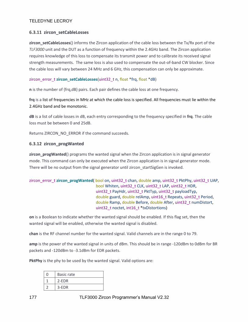
TELEDYNE LECROY
177 TLF3000 Zircon Programmer’s Manual V2.32
6.3.11 zircon_setCableLosses
zircon_setCableLosses() informs the Zircon application of the cable loss between the Tx/Rx port of the
TLF3000 unit and the DUT as a function of frequency within the 2.4GHz band. The Zircon application
requires knowledge of this loss to compensate its transmit power and to calibrate its received signal
strength measurements. The same loss is also used to compensate the out-of-band CW blocker. Since
the cable loss will vary between 24 MHz and 6 GHz, this compensation can only be approximate.
zircon_error_t zircon_setCableLosses(uint32_t n, float *frq, float *dB)
n is the number of frq,dB pairs. Each pair defines the cable loss at one frequency.
frq is a list of frequencies in MHz at which the cable loss is specified. All frequencies must lie within the
2.4GHz band and be monotonic.
dB is a list of cable losses in dB, each entry corresponding to the frequency specified in frq. The cable
loss must be between 0 and 25dB.
Returns ZIRCON_NO_ERROR if the command succeeds.
6.3.12 zircon_progWanted
zircon_progWanted() programs the wanted signal when the Zircon application is in signal generator
mode. This command can only be executed when the Zircon application is in signal generator mode.
There will be no output from the signal generator until zircon_startSigGen is invoked.
zircon_error_t zircon_progWanted( bool on, uint32_t chan, double amp, uint32_t PktPhy, uint32_t UAP, bool Whiten, uint32_t CLK, uint32_t LAP, uint32_t HDR, uint32_t PayHdr, uint32_t PktTyp, uint32_t payloadTyp, double guard, double relAmp, uint16_t Repeats, uint32_t Period, double Ramp, double Before, double After, uint32_t numDistort, uint32_t noctet, int16_t *txDistortions)
on is a Boolean to indicate whether the wanted signal should be enabled. If this flag set, then the
wanted signal will be enabled, otherwise the wanted signal is disabled.
chan is the RF channel number for the wanted signal. Valid channels are in the range 0 to 79.
amp is the power of the wanted signal in units of dBm. This should be in range -120dBm to 0dBm for BR
packets and -120dBm to -3.1dBm for EDR packets.
PktPhy is the phy to be used by the wanted signal. Valid options are:
0 Basic rate
1 2-EDR
2 3-EDR
TELEDYNE LECROY
178 TLF3000 Zircon Programmer’s Manual V2.32
UAP is the UAP of the Bluetooth address. This is required to generate the HEC for the header.
Whiten is a Boolean. If True the packet will be whitened. If False, the packet will not be whitened.
CLK is the current value of the central clock. The LSBs are used for whitening the packet. If whitening is
not enabled, then this parameter is ignored.
LAP is the 24bit LAP of the Bluetooth address.
HDR is the 10bits of the header without the HEC. The header bits denoting the packet type are ignored
and are set on the basis of the parameter pktTyp.
PayHdr is the appropriate payload header for the selected packet type. The length field in the payload
header is ignored and filled using the contents of the parameter octets.

TELEDYNE LECROY
179 TLF3000 Zircon Programmer’s Manual V2.32
PktTyp is the type of packet to be transmitted:
0 ID
1 Null
2 Poll
3 FHS
4 DM1
5 DH1
6 DM3
7 DH3
8 DM5
9 DH5
10 AUX1
11 2-DH1
12 2-DH3
13 2-DH5
14 3-DH1
15 3-DH3
16 3-DH5
17 HV1
18 HV2
19 HV3
20 DV
21 EV3
22 EV4
23 EV5
24 2-EV3
25 2-EV5
26 3-EV3
27 3-EV5
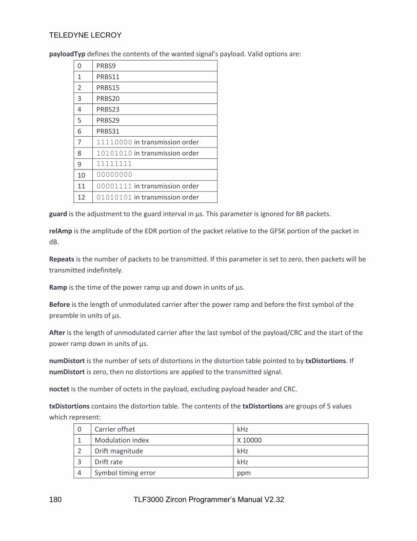
TELEDYNE LECROY
180 TLF3000 Zircon Programmer’s Manual V2.32
payloadTyp defines the contents of the wanted signal’s payload. Valid options are:
0 PRBS9
1 PRBS11
2 PRBS15
3 PRBS20
4 PRBS23
5 PRBS29
6 PRBS31
7 11110000 in transmission order
8 10101010 in transmission order
9 11111111
10 00000000
11 00001111 in transmission order
12 01010101 in transmission order
guard is the adjustment to the guard interval in µs. This parameter is ignored for BR packets.
relAmp is the amplitude of the EDR portion of the packet relative to the GFSK portion of the packet in
dB.
Repeats is the number of packets to be transmitted. If this parameter is set to zero, then packets will be
transmitted indefinitely.
Ramp is the time of the power ramp up and down in units of µs.
Before is the length of unmodulated carrier after the power ramp and before the first symbol of the
preamble in units of µs.
After is the length of unmodulated carrier after the last symbol of the payload/CRC and the start of the
power ramp down in units of µs.
numDistort is the number of sets of distortions in the distortion table pointed to by txDistortions. If
numDistort is zero, then no distortions are applied to the transmitted signal.
noctet is the number of octets in the payload, excluding payload header and CRC.
txDistortions contains the distortion table. The contents of the txDistortions are groups of 5 values
which represent:
0 Carrier offset kHz
1 Modulation index X 10000
2 Drift magnitude kHz
3 Drift rate kHz
4 Symbol timing error ppm

TELEDYNE LECROY
181 TLF3000 Zircon Programmer’s Manual V2.32
For basic rate packets, each group of distortions is repeated for 20ms before moving onto the next
group of distortions in the table. Once the table has been exhausted, it is restarted from the top. For
EDR packets each group of distortions is repeated 20 times. The sign of the carrier drift is automatically
reversed by the Zircon application on alternate packets.
Returns ZIRCON_NO_ERROR if the command succeeds.
6.3.13 zircon_progInterferer
zircon_progInterferer() programs the modulated interferer signal generator when the Zircon application
is in signal generator mode. This command can only be executed when the Zircon application is in signal
generator mode. There will be no output from the signal generator until zircon_startSigGen is invoked.
The interferer is modulated by a PRBS15 sequence.
zircon_error_t zircon_progInterferer( bool On, bool Cont, double Amp, uint32_t Phy, uint32_t Octets,
uint32_t Freq, double Period)
On is a Boolean to indicate whether the modulated interferer signal generator should be enabled. If this
flag is set, then the modulated interferer signal generator is enabled, otherwise the modulated
interferer signal generator is disabled.
Cont indicates whether the inteferer is a continuous transmission or packetised. If this parameter is
True, then the interferer is a continuous transmission. If this parameter is False then the interferer is a
packetised transmiision,
Amp is the power of the modulated interferer signal in dBm. Valid range is -120dBm to 0dBm for a basic
rate interferer and -120dBm to -3.1dBm for an EDR interferer.
Phy is the phy to be used by the modulated interferer signal. Valid options are:
0 Basic rate
1 2-EDR
2 3-EDR
Octets determines the number of octets in the packet payload for packetised transmissions. This
parameter is ignored it Cont is True.
Freq is the transmission frequency of the interferer in units of MHz.
Period is the interval between the start of one packet of the interferer and the start of the subsequent
packet in units of µs. This parameter is ignored if Cont is True.
Returns ZIRCON_NO_ERROR if the command succeeds.

TELEDYNE LECROY
182 TLF3000 Zircon Programmer’s Manual V2.32
6.3.14 zircon_progCW
zircon_progCW() programs the in-band CW signal generator when the Zircon application is in signal
generator mode. This command can only be executed when the Zircon application is in signal generator
mode. There will be no output from the signal generator until zircon_startSigGen is invoked.
zircon_error_t zircon_progCW( uint32_t cw, bool on, double amp, uint32_t freq )
cw indicates which of the two in-band CW sources is being programmed. Valid values are 0 and 1.
on is a Boolean to indicate whether the in-band CW generator should be enabled. If set, then the in-
band CW generator is enabled, otherwise the in-band CW generator is disabled.
amp is the power of the in-band CW signal in units of dBm. Valid range is -120 dBm to 0 dBm.
freq is the frequency of the in-band CW signal in Hz. Valid range is 2,395,000,000 Hz to 2,485,000,000 Hz
inclusive.
Returns ZIRCON_NO_ERROR if the command succeeds.
6.3.15 zircon_progAWGN
zircon_progAWGN programs the AWGN generator when the Zircon application is in signal generator
mode. This command can only be executed when the Zircon application is in signal generator mode.
There will be no output from the signal generator until zircon_startSigGen is invoked.
zircon_error_t zircon_progAWGN( bool on, double amp )
on is a Boolean to indicate whether the AWGN generator should be enabled. If set, then the AWGN
generator is enabled, otherwise the AWGN generator is disabled.
amp is the power of the AWGN signal in units of dBm/MHz. Valid range is -162 dBm/MHz to -42
dBm/MHz.
Returns ZIRCON_NO_ERROR if the command succeeds.
6.3.16 zircon_progOutOfBandCW
zircon_progOutOfBandCW programs the out-of-band CW signal generator when the Zircon application
is in signal generator mode. This command can only be executed when the Zircon application is in signal
generator mode. There will be no output from the signal generator until zircon_startSigGen is invoked.
zircon_error_t zircon_progOutOfBandCW( bool on, double amp, uint32_t freq )
on is a Boolean to indicate whether the out-of-band CW generator should be enabled. If set, then the
out-of-band CW generator is enabled, otherwise the out-of-band CW generator is disabled.

TELEDYNE LECROY
183 TLF3000 Zircon Programmer’s Manual V2.32
amp is the power of the out-of-band CW signal in units of dBm. Valid range is -50dBm to -28 dBm.
freq is the frequency of the out-of-band CW signal in MHz. Valid range is 24 MHz to 6,000 MHz.
Returns ZIRCON_NO_ERROR if the command succeeds.
6.3.17 zircon_startSigGen
zircon_startSSigGen determines when the signal generator is active. This is a global enable for the signal
generator output; it overrides the individual on fields for the wanted signal, modulated interferer, in-
band CW, AWGN and out-of-band CW. This command can only be executed when the Zircon application
is in signal generator mode.
zircon_error_t zircon_startSigGen(void)
Returns ZIRCON_NO_ERROR if the command succeeds.
6.3.18 zircon_stopSigGen
zircon_stopSigGen will stop all output from the signal generator. It will not affect the programming of
the various signal sources, ie the wanted signal, modulated interferer, in-band CW, AWGN and out-of-
band CW. This command can only be executed when the Zircon application is in signal generator mode.
zircon_error_t zircon_stopSigGen(void)
Returns ZIRCON_NO_ERROR if the command succeeds.
6.3.19 zircon_startSigAna
zircon_startSigAna() starts the signal analyser. This command can only be executed when the Zircon
application is in signal analyser mode.
zircon_error_t zircon_startSigAna(uint32_t super, double rssiThreshold)
super is the supervision timeout for the link in ms. This parameter is ignored if the Zircon application is
not currently controlling a DUT.
rssiTthreshold Only packets with an RSSI greater than rssiThreshold will be analysed. rssiThreshold is in
units of dBm.
Returns ZIRCON_NO_ERROR if the command succeeds.

TELEDYNE LECROY
184 TLF3000 Zircon Programmer’s Manual V2.32
6.3.20 Zircon_stopSigAna
Zircon_stopSigAna() will stop the signal analyser running. This command can only be executed when the
Zircon application is in signal analyser mode.
zircon_error_t zircon_stopSigAna(void)
Returns ZIRCON_NO_ERROR if the command succeeds.
6.3.21 zircon_pollResultsTable
zircon_pollResultsTable() returns results in a tabular form when operating in signal analyser mode.
The results contributing to the returned table are filtered by:
1. An RF channel filter
2. A phy filter
3. A packet slot filter
If the phy filter contains basic rate packets, then only results for basic rate packets will be returned. If
the phy filter does not contain basic rate packets, then only results for EDR packets will be returned. All
packets which satisfy the RF channel and packet slot filter will contribute to the statistics returned in the
table.
zircon_error_t zircon_pollResultsTable(uint32_t meas, uint8_t *chanMask, uint32_t phyMask ,
uint32_t slotMask, float *res, uint32_t maxRes,
uint32_t *numRes)
meas is the measurement set for which tabular results are requested. Possible values are:
Meas Measurement set
0x00000000 Output power
0x00000001 Modulation characteristics
0x00000002 Carrier offset & drift
0x00000003 Spectrum
0x00000004 BER
chanMask is an array of uint8_t containing a 79 bit mask which is the RF channel filter. Only packets
which pass the RF channel filter results will contribute to the statistics in the returned table. A ‘1’ in the
mask indicates that the corresponding RF channel results should be included in the table, a ‘0’ in the
mask indicates that the corresponding RF channel results should be ignored.

TELEDYNE LECROY
185 TLF3000 Zircon Programmer’s Manual V2.32
phyMask is a 3 bit mask containing the phy filter. If basic rate is selected in the mask, then only results
for basic rate packets will be returned. If basic rate is not set, then combined results for the remaining
selected phys will be returned.
Bit Position Bit Mask Phy
0 0x01 Basic rate
1 0x02 2-EDR
2 0x04 3-EDR
slotMask. this mask contains the packet slot filter. Only packets which pass the packet slot filter will
contribute to the statistics in the returned table. If a bit is ‘1’, then the results for the corresponding
packet slot will contribute to the statistics in the returned table. If a bit is ‘0’, then the results for the
corresponding slot are ignored.
Bit Position Bit Mask Packet slots
0 0x01 1 slot packets
1 0x02 3 slot packets
2 0x04 5 slot packets
res is an array to receive the the requested table of results. The first 5 values in table correspond to the
first row in the table, the second 5 values to the second row, etc. The tables returned for the various
measurement sets are:
1. Basic rate output power
Quantity Packet Count Minimum Maximum Average Current
Pavg
Pk - Pavg
EDR output power
Quantity Packet Count Minimum Maximum Average Current
Pavg
PGFSK - PDPSK
Guard- 99%
Guard+ 99%
Guard > 4.6µs
Guard < 5.4µs
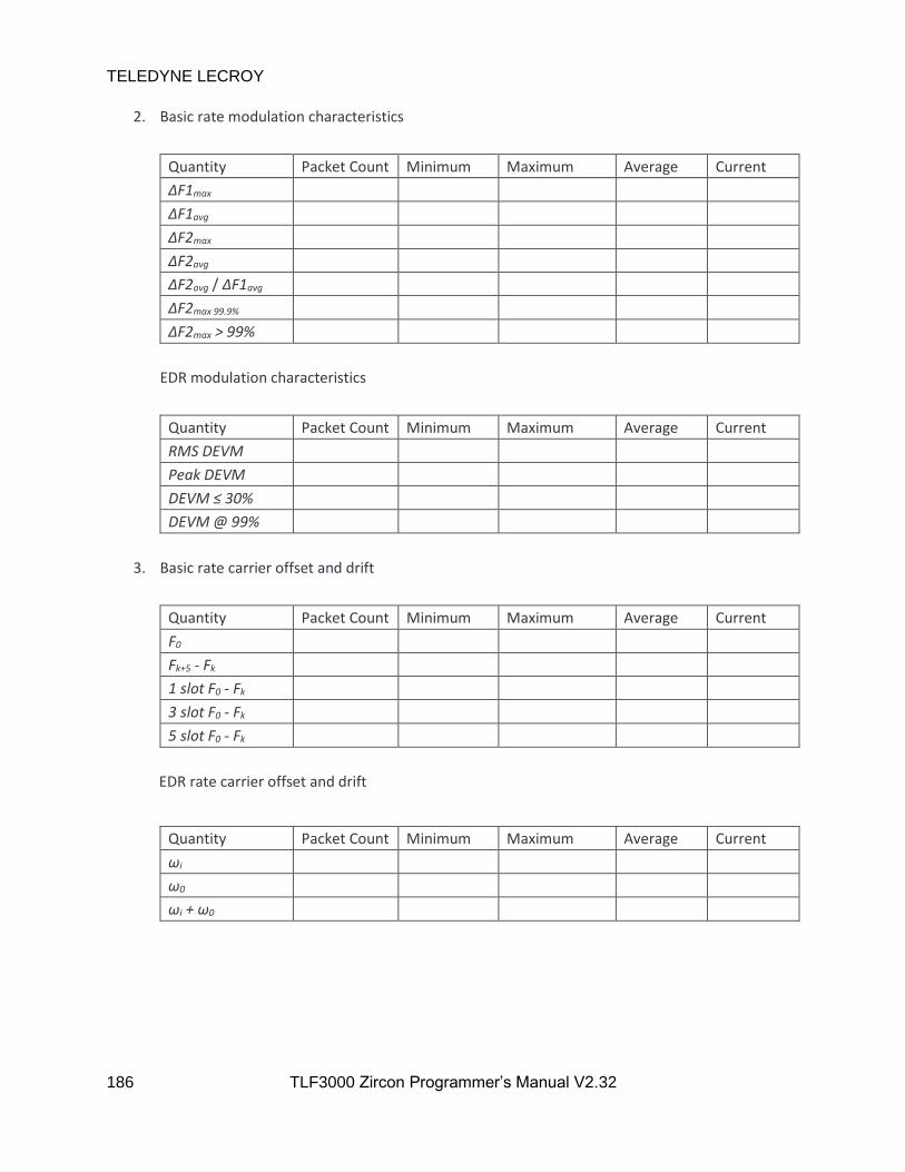
TELEDYNE LECROY
186 TLF3000 Zircon Programmer’s Manual V2.32
2. Basic rate modulation characteristics
Quantity Packet Count Minimum Maximum Average Current
ΔF1max
ΔF1avg
ΔF2max
ΔF2avg
ΔF2avg / ΔF1avg
ΔF2max 99.9%
ΔF2max > 99%
EDR modulation characteristics
Quantity Packet Count Minimum Maximum Average Current
RMS DEVM
Peak DEVM
DEVM ≤ 30%
DEVM @ 99%
3. Basic rate carrier offset and drift
Quantity Packet Count Minimum Maximum Average Current
F0
Fk+5 - Fk
1 slot F0 - Fk
3 slot F0 - Fk
5 slot F0 - Fk
EDR rate carrier offset and drift
Quantity Packet Count Minimum Maximum Average Current
ωi
ω0
ωi + ω0

TELEDYNE LECROY
187 TLF3000 Zircon Programmer’s Manual V2.32
4. Basic rate spectrum
Quantity Packet Count Minimum Maximum Average Current
Fl
Fh
ΔF
Ftx ± 2MHz
Ftx ± (3+n)MHz
# Exceptions
Max exception
Power density
EDR spectrum
Quantity Packet Count Minimum Maximum Average Current
Fl
Fh
ΔF
Ptx26 - Ptxref
Ftx ± 2MHz
Ftx ± (3+n)MHz
# Exceptions
Max exception
Power density
5. BER
Quantity Packet Count Minimum Maximum Average Current
Log10(BER)
Packet loss rate
maxRes is the maximum number of entries which can be returned in res.
numRes is the number of entries which were returned in res.
Returns ZIRCON_NO_ERROR if the command succeeds.
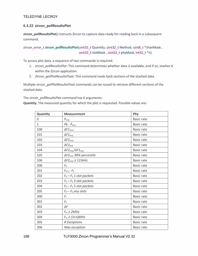
TELEDYNE LECROY
188 TLF3000 Zircon Programmer’s Manual V2.32
6.3.22 zircon_pollResultsPlot
zircon_pollResultsPlot() instructs Zircon to capture data ready for reading back in a subsequent
command.
zircon_error_t zircon_pollResultsPlot(uint32_t Quantity, uint32_t Method, uint8_t *chanMask ,
uint32_t slotMask , uint32_t phyMask, int32_t *n)
To access plot data, a sequence of two commands is required:
1. zircon_pollResultsPlot. This command determines whether data is available, and if so, stashes it
within the Zircon application.
2. Zircon_getPlotResultsFloat. This command reads back sections of the stashed data.
Multiple zircon_getPlotResultsFloat commands can be issued to retrieve different sections of the
stashed data.
The zircon_pollResultsPlot command has 6 arguments:
Quantity. The measured quantity for which the plot is requested. Possible values are:
Quantity Measurement Phy
0 Pavg Basic rate
1 Pk - Pavg Basic rate
100 ΔF1max Basic rate
101 ΔF1avg Basic rate
102 ΔF2max Basic rate
103 ΔF2avg Basic rate
104 ΔF2avg /ΔF1avg Basic rate
105 ΔF2max 99% percentile Basic rate
106 ΔF2max ≥ 115kHz Basic rate
200 F0 Basic rate
201 Fk+5 - Fk Basic rate
202 F0 – Fk 1 slot packets Basic rate
203 F0 – Fk 3 slot packets Basic rate
204 F0 – Fk 5 slot packets Basic rate
205 F0 – Fk any slots Basic rate
300 Fl Basic rate
301 Fh Basic rate
302 ΔF Basic rate
303 Ftx ± 2MHz Basic rate
304 Ftx ± (3+n)MHz Basic rate
305 # Exceptions Basic rate
306 Max exception Basic rate

TELEDYNE LECROY
189 TLF3000 Zircon Programmer’s Manual V2.32
307 Power density Basic rate
400 BER Basic rate
401 PER Basic rate
1000 Pavg 2-EDR
1001 PGFSK - PDPSK 2-EDR
1002 Guard- 99% 2-EDR
1003 Guard+ 99% 2-EDR
1004 Guard > 4.6µs 2-EDR
1005 Guard < 5.4µs 2-EDR
1050 Guard 2-EDR
1100 RMS DEVM 2-EDR
1101 Peak DEVM 2-EDR
1102 DEVM ≤ 30% 2-EDR
1103 DEVM @ 99% 2-EDR
1150 DEVM 2-EDR
1200 ωi 2-EDR
1201 ω0 2-EDR
1202 ωi + ω0 2-EDR
1300 Fl 2-EDR
1301 Fh 2-EDR
1302 ΔF 2-EDR
1303 Ptx26 - Ptxref 2-EDR
1304 Ftx ± 2MHz 2-EDR
1305 Ftx ± (3+n)MHz 2-EDR
1306 # Exceptions 2-EDR
1307 Max exception 2-EDR
1308 Power density 2-EDR
1400 BER 2-EDR
1401 PER 2-EDR
2000 Pavg 3-EDR
2001 PGFSK - PDPSK 3-EDR
2002 Guard- 99% 3-EDR
2003 Guard+ 99% 3-EDR
2004 Guard > 4.6µs 3-EDR
2005 Guard < 5.4µs 3-EDR
2050 Guard 3-EDR
2100 RMS DEVM 3-EDR
2101 Peak DEVM 3-EDR
2102 DEVM ≤ 30% 3-EDR
2103 DEVM @ 99% 3-EDR
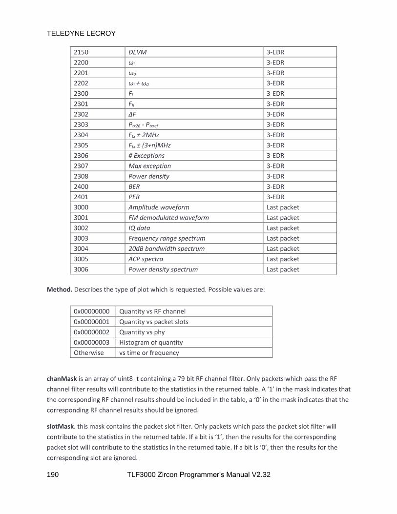
TELEDYNE LECROY
190 TLF3000 Zircon Programmer’s Manual V2.32
2150 DEVM 3-EDR
2200 ωi 3-EDR
2201 ω0 3-EDR
2202 ωi + ω0 3-EDR
2300 Fl 3-EDR
2301 Fh 3-EDR
2302 ΔF 3-EDR
2303 Ptx26 - Ptxref 3-EDR
2304 Ftx ± 2MHz 3-EDR
2305 Ftx ± (3+n)MHz 3-EDR
2306 # Exceptions 3-EDR
2307 Max exception 3-EDR
2308 Power density 3-EDR
2400 BER 3-EDR
2401 PER 3-EDR
3000 Amplitude waveform Last packet
3001 FM demodulated waveform Last packet
3002 IQ data Last packet
3003 Frequency range spectrum Last packet
3004 20dB bandwidth spectrum Last packet
3005 ACP spectra Last packet
3006 Power density spectrum Last packet
Method. Describes the type of plot which is requested. Possible values are:
0x00000000 Quantity vs RF channel
0x00000001 Quantity vs packet slots
0x00000002 Quantity vs phy
0x00000003 Histogram of quantity
Otherwise vs time or frequency
chanMask is an array of uint8_t containing a 79 bit RF channel filter. Only packets which pass the RF
channel filter results will contribute to the statistics in the returned table. A ‘1’ in the mask indicates that
the corresponding RF channel results should be included in the table, a ‘0’ in the mask indicates that the
corresponding RF channel results should be ignored.
slotMask. this mask contains the packet slot filter. Only packets which pass the packet slot filter will
contribute to the statistics in the returned table. If a bit is ‘1’, then the results for the corresponding
packet slot will contribute to the statistics in the returned table. If a bit is ‘0’, then the results for the
corresponding slot are ignored.
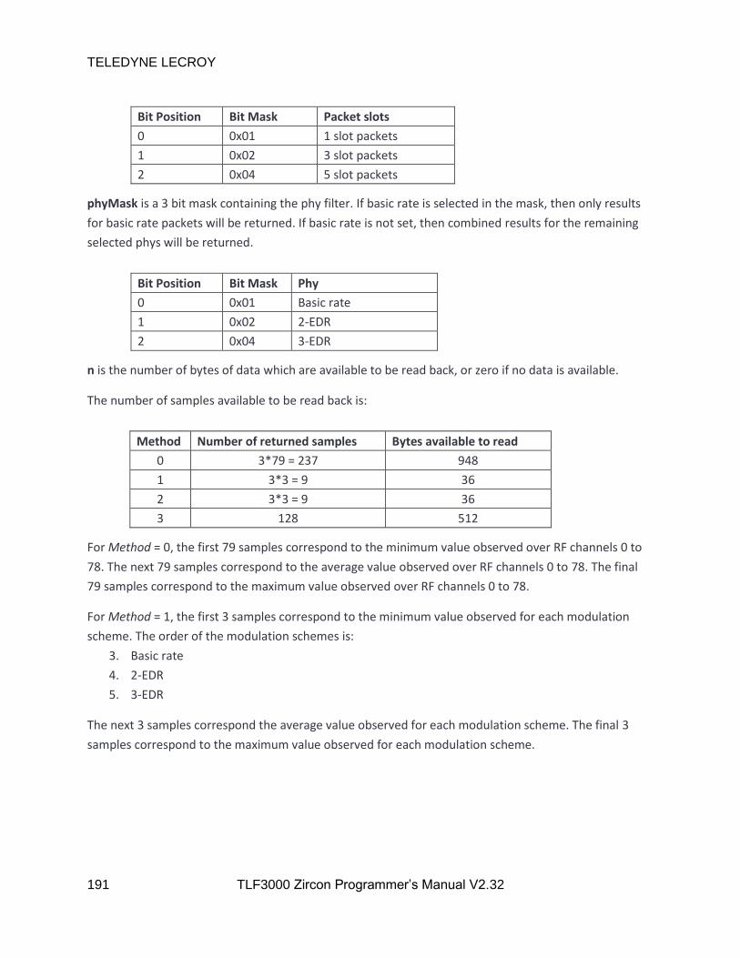
TELEDYNE LECROY
191 TLF3000 Zircon Programmer’s Manual V2.32
Bit Position Bit Mask Packet slots
0 0x01 1 slot packets
1 0x02 3 slot packets
2 0x04 5 slot packets
phyMask is a 3 bit mask containing the phy filter. If basic rate is selected in the mask, then only results
for basic rate packets will be returned. If basic rate is not set, then combined results for the remaining
selected phys will be returned.
Bit Position Bit Mask Phy
0 0x01 Basic rate
1 0x02 2-EDR
2 0x04 3-EDR
n is the number of bytes of data which are available to be read back, or zero if no data is available.
The number of samples available to be read back is:
Method Number of returned samples Bytes available to read
0 3*79 = 237 948
1 3*3 = 9 36
2 3*3 = 9 36
3 128 512
For Method = 0, the first 79 samples correspond to the minimum value observed over RF channels 0 to
78. The next 79 samples correspond to the average value observed over RF channels 0 to 78. The final
79 samples correspond to the maximum value observed over RF channels 0 to 78.
For Method = 1, the first 3 samples correspond to the minimum value observed for each modulation
scheme. The order of the modulation schemes is:
3. Basic rate
4. 2-EDR
5. 3-EDR
The next 3 samples correspond the average value observed for each modulation scheme. The final 3
samples correspond to the maximum value observed for each modulation scheme.

TELEDYNE LECROY
192 TLF3000 Zircon Programmer’s Manual V2.32
For Method = 2, the first 3 samples correspond the minimum value observed for each of the packet slot
lengths. The next 3 samples correspond the average value observed for each of the packet slot lengths.
The final 3 samples correspond to the maximum value observed for each of the packet slot lengths. The
order of the packet slot lengths is:
1. 1 slot packets
2. 3 slot packets
3. 5 slot packets
The units of the returned quantities are:
Measurement Units
Pavg dBm
Pk - Pavg dB
ΔF1max kHz
ΔF1avg kHz
ΔF2max kHz
ΔF2avg kHz
ΔF2avg /ΔF1avg Dimensionless
ΔF2max 99% percentile kHz
ΔF2max ≥ 115kHz kHz
F0 kHz
Fk+5 - Fk kHz
F0 – Fk 1 slot packets kHz
F0 – Fk 3 slot packets kHz
F0 – Fk 5 slot packets dBm
F0 – Fk any slots dBm
Fl Dimensionless
Fh dBm
ΔF dBm
Ftx ± 2MHz dBm
Ftx ± (3+n)MHz kHz
# Exceptions kHz
Max exception kHz
Power density kHz
PGFSK - PDPSK dB
Guard- 99% µs
Guard+ 99% µs
Guard > 4.6µs %
Guard < 5.4µs %
Guard µs
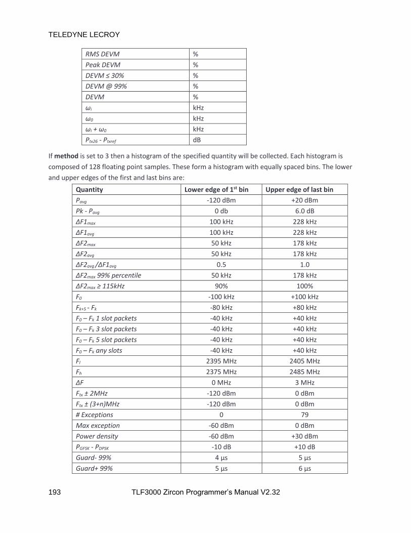
TELEDYNE LECROY
193 TLF3000 Zircon Programmer’s Manual V2.32
RMS DEVM %
Peak DEVM %
DEVM ≤ 30% %
DEVM @ 99% %
DEVM %
ωi kHz
ω0 kHz
ωi + ω0 kHz
Ptx26 - Ptxref dB
If method is set to 3 then a histogram of the specified quantity will be collected. Each histogram is
composed of 128 floating point samples. These form a histogram with equally spaced bins. The lower
and upper edges of the first and last bins are:
Quantity Lower edge of 1st bin Upper edge of last bin
Pavg -120 dBm +20 dBm
Pk - Pavg 0 db 6.0 dB
ΔF1max 100 kHz 228 kHz
ΔF1avg 100 kHz 228 kHz
ΔF2max 50 kHz 178 kHz
ΔF2avg 50 kHz 178 kHz
ΔF2avg /ΔF1avg 0.5 1.0
ΔF2max 99% percentile 50 kHz 178 kHz
ΔF2max ≥ 115kHz 90% 100%
F0 -100 kHz +100 kHz
Fk+5 - Fk -80 kHz +80 kHz
F0 – Fk 1 slot packets -40 kHz +40 kHz
F0 – Fk 3 slot packets -40 kHz +40 kHz
F0 – Fk 5 slot packets -40 kHz +40 kHz
F0 – Fk any slots -40 kHz +40 kHz
Fl 2395 MHz 2405 MHz
Fh 2375 MHz 2485 MHz
ΔF 0 MHz 3 MHz
Ftx ± 2MHz -120 dBm 0 dBm
Ftx ± (3+n)MHz -120 dBm 0 dBm
# Exceptions 0 79
Max exception -60 dBm 0 dBm
Power density -60 dBm +30 dBm
PGFSK - PDPSK -10 dB +10 dB
Guard- 99% 4 µs 5 µs
Guard+ 99% 5 µs 6 µs

TELEDYNE LECROY
194 TLF3000 Zircon Programmer’s Manual V2.32
Guard > 4.6µs 0 % 100 %
Guard < 5.4µs 0 % 100 %
Guard 4 µs 6 µs
RMS DEVM 0 % 50 %
Peak DEVM 0 % 80 %
DEVM ≤ 30% 0 % 50 %
DEVM @ 99% 0 % 100 %
DEVM 0 % 80 %
ωi -100 kHz +100 kHz
ω0 -100 kHz +100 kHz
ωi + ω0 -100 kHz +100 kHz
Ptx26 - Ptxref -60 dB 0 dB
If method is set to 4, then the specified quantity is collected as a function of time or frequency.
For those quantities which are collected as a function of time, the saved data consists of 28 bytes of
meta data followed by the requested quantity as a series of floating point numbers. The meta data is
composed of 7 uint32_t:
1. uint32_t : MSB. MSB of timestamp of packet P0 location in units of 250 ns since the Unix epoch
of 1970-01-01 00:00:00 + 0000 (UTC).
2. uint32_t : LSB. LSB of timestamp of packet P0 location in units of 250 ns since the Unix epoch of
1970-01-01 00:00:00 + 0000 (UTC).
3. uint32_t : N. The number of samples available.
4. uint32_t : RF Chan. The RF channel number on which the packet was collected.
5. uint32_t : Slots. Indicates the number of slots in the packet. Possible values are:
0 1 slot packet
1 3 slot packet
2 5 slot packet
6. uint32_t : Phy. phy of the packet for which the data was collected. Possible values are:
0 Basic rate
1 2-EDR
2 3-EDR
7. uint32_t : Bits. The number of bits in the packet payload.
The units of the returned quantities are the same as for methods 1, 2 and 3.

TELEDYNE LECROY
195 TLF3000 Zircon Programmer’s Manual V2.32
For basic rate packets:
1. The first samples of ΔF1max and ΔF2max correspond to bit 4 of the payload. The interval between
samples is 1 bit. Samples which are not valid contain NaN.
2. The first samples of Fn correspond to the average starting at bit 1 of the payload. The interval
between samples is 10 bits. These samples are used to derive F0 - Fn and Fn+5 – Fn.
Amplitude, FM deviation and IQ data commence 15µs prior to the starts of the packet and continue for
15µs past the end of the packet.
For ACP spectra the data which can be read back represents in-band emissions as a function of
frequency. Results are available for both the final 1MHz resolution spectrum and the 100kHz resolution
spectrum which was summed to generate the 1MHz spectrum. This provides greater visibility of what is
dominating the in-band emissions.
The available data can contain the following fields:
1. 91*float : Curr_1MHz. The last recorded value of the in-band emissions as a function of
frequency from 2395MHz to 2485 MHz.
2. 910*float : Curr_100kHz. The last recorded values of the 100 kHz spectrum summed to generate
the in-band emissions spectrum as a function of frequency from 24394.550 MHz to 2485.450
MHz.
For frequency range or power density spectra, data which can be read back are 100kHz resolution
spectra spanning from 2395MHz to 2485MHz. There are 901 float available for reading back.
For 20dB bandwidth spectra, data which can be read back consist of 81*200 float. These cover
2400.5MHz to 2481.5MHz in steps of 5kHz. Only those 600 points centred on the channel of the last
packet which satisfied the filters will be populated.
All spectra are in units of dBm.
Returns ZIRCON_NO_ERROR if the command succeeds.
6.3.23 zircon_getResultsPlotFloat
zircon_getResultsPlotFloat() reads back the data which was captured using a previous
zircon_polltResultsPlot() command. This command should be used when the captured data consisted of
an array of float.
zircon_error_t zircon_getResultsPlotFloat(uint32_t offset, uint32_t n, float *res)
offset is the offset from the start of the buffer of the data to be read back (see zircon_pollResultsPlot).
The offset is in units of 4 bytes.
n is the number of float to be read back from the buffer.

TELEDYNE LECROY
196 TLF3000 Zircon Programmer’s Manual V2.32
res is the data read back from the buffer.
Returns ZIRCON_NO_ERROR if the command succeeds.
6.3.24 zircon_clearResults
zircon_clearResults() erases all test results accumulated in the Zircon application by the signal analyser
mode or the phy tester mode. This command can be executed at any time.
zircon_error_t zircon_clearResults( void )
Returns ZIRCON_NO_ERROR if the command succeeds.
6.3.25 zircon_setLimits
zircon_setLimits() informs the Zircon application of the test limits to be applied. The test limits are used
in phy tester mode and signal analyser mode. This command can be executed at anytime.
zircon_error_t zircon_setLimits( int16_t *limits )
limits is an int16_t array with 53 entries containing the limits:
Limit Test Quantity Phy Limit type Units
1 Ouput power Pavg BR Lower 0.1 dBm
2 Ouput power Pavg BR Upper 0.1 dBm
3 Modulation characteristics ΔF1avg BR Lower 100 Hz
4 Modulation characteristics ΔF1avg BR Upper 100 Hz
5 Modulation characteristics ΔF2avg /ΔF1avg BR Lower 0.001
6 Modulation characteristics ΔF2 99.9% percentile BR - 100 Hz
7 Modulation characteristics ΔF2 ≤ 115 kHz BR 0.01%
8 Carrier frequency & drift F0 BR Lower 100 Hz
9 Carrier frequency & drift F0 BR Upper 100 Hz
10 Carrier frequency & drift Fk+5 – Fk BR Lower 100 Hz
11 Carrier frequency & drift Fk+5 – Fk BR Upper 100 Hz
12 Carrier frequency & drift F0 – Fk 1 slot packets BR Lower 100 Hz
13 Carrier frequency & drift F0 – Fk 1 slot packets BR Upper 100 Hz
14 Carrier frequency & drift F0 – Fk 3 slot packets BR Lower 100 Hz
15 Carrier frequency & drift F0 – Fk 3 slot packets BR Upper 100 Hz
16 Carrier frequency & drift F0 – Fk 5 slot packets BR Lower 100 Hz
17 Carrier frequency & drift F0 – Fk 5 slot packets BR Upper 100 Hz
18 Ouput power Pavg 2-EDR Lower 0.1 dBm
19 Ouput power Pavg 2-EDR Upper 0.1 dBm
20 Modulation characteristics PGFSK - PDPSK 2-EDR Lower 0.1 dB
21 Modulation characteristics PGFSK - PDPSK 2-EDR Upper 0.1 dB
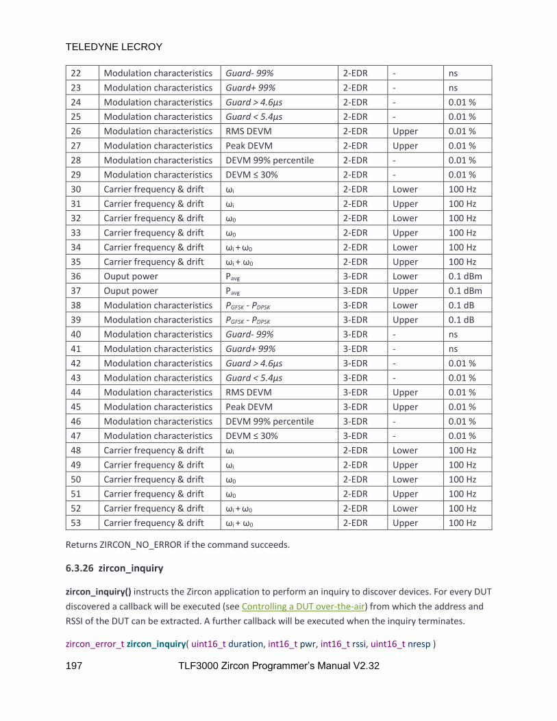
TELEDYNE LECROY
197 TLF3000 Zircon Programmer’s Manual V2.32
22 Modulation characteristics Guard- 99% 2-EDR - ns
23 Modulation characteristics Guard+ 99% 2-EDR - ns
24 Modulation characteristics Guard > 4.6µs 2-EDR - 0.01 %
25 Modulation characteristics Guard < 5.4µs 2-EDR - 0.01 %
26 Modulation characteristics RMS DEVM 2-EDR Upper 0.01 %
27 Modulation characteristics Peak DEVM 2-EDR Upper 0.01 %
28 Modulation characteristics DEVM 99% percentile 2-EDR - 0.01 %
29 Modulation characteristics DEVM ≤ 30% 2-EDR - 0.01 %
30 Carrier frequency & drift ωi 2-EDR Lower 100 Hz
31 Carrier frequency & drift ωi 2-EDR Upper 100 Hz
32 Carrier frequency & drift ω0 2-EDR Lower 100 Hz
33 Carrier frequency & drift ω0 2-EDR Upper 100 Hz
34 Carrier frequency & drift ωi + ω0 2-EDR Lower 100 Hz
35 Carrier frequency & drift ωi + ω0 2-EDR Upper 100 Hz
36 Ouput power Pavg 3-EDR Lower 0.1 dBm
37 Ouput power Pavg 3-EDR Upper 0.1 dBm
38 Modulation characteristics PGFSK - PDPSK 3-EDR Lower 0.1 dB
39 Modulation characteristics PGFSK - PDPSK 3-EDR Upper 0.1 dB
40 Modulation characteristics Guard- 99% 3-EDR - ns
41 Modulation characteristics Guard+ 99% 3-EDR - ns
42 Modulation characteristics Guard > 4.6µs 3-EDR - 0.01 %
43 Modulation characteristics Guard < 5.4µs 3-EDR - 0.01 %
44 Modulation characteristics RMS DEVM 3-EDR Upper 0.01 %
45 Modulation characteristics Peak DEVM 3-EDR Upper 0.01 %
46 Modulation characteristics DEVM 99% percentile 3-EDR - 0.01 %
47 Modulation characteristics DEVM ≤ 30% 3-EDR - 0.01 %
48 Carrier frequency & drift ωi 2-EDR Lower 100 Hz
49 Carrier frequency & drift ωi 2-EDR Upper 100 Hz
50 Carrier frequency & drift ω0 2-EDR Lower 100 Hz
51 Carrier frequency & drift ω0 2-EDR Upper 100 Hz
52 Carrier frequency & drift ωi + ω0 2-EDR Lower 100 Hz
53 Carrier frequency & drift ωi + ω0 2-EDR Upper 100 Hz
Returns ZIRCON_NO_ERROR if the command succeeds.
6.3.26 zircon_inquiry
zircon_inquiry() instructs the Zircon application to perform an inquiry to discover devices. For every DUT
discovered a callback will be executed (see Controlling a DUT over-the-air) from which the address and
RSSI of the DUT can be extracted. A further callback will be executed when the inquiry terminates.
zircon_error_t zircon_inquiry( uint16_t duration, int16_t pwr, int16_t rssi, uint16_t nresp )

TELEDYNE LECROY
198 TLF3000 Zircon Programmer’s Manual V2.32
duration is the maximum time for the inquiry in ms. Once this time has expired the inquiry will
terminate.
pwr is the power for the inquiry packets in dBm. The Zircon application transmits on all inquiry channels
simultaneously. If the inquiry scan activity of the DUT is set to ensure the DUT listens frequently, then
the DUT will be discovered almost instantaneously. Because the Zircon application is transmitting on all
inquiry channels simultaneously, the maximum power per channel is limited to -30dBm.
rssi is an RSSI threshold. Packets which are below the RSSI threshold will be ignored. This can be used to
ensure that only nearby devices are found. Units are in dBm.
nresp is the maximum number of inquiry responses required. Once nresp devices have been found the
inquiry will be terminated. Hence if there is only one device that needs to be found the inquiry can be
terminated as soon as that device is located. If nresp is set to zero, then there is no limit on the number
of inquiry responses.
Returns ZIRCON_NO_ERROR if the command succeeds.
6.3.27 zircon_page
zircon_page() instructs the Zircon application to connect to a device and attempt to place it into test
mode. It can also be used to terminate a connection. A callback is executed whenever a connection is
terminated. See Controlling a DUT over-the-air.
zircon_error_t zircon_page( bool run, uint64_t addr, uint16_t timeout, double pagePwr, double pollPwr,
double tstPwr, double rssi, uint16_t super )
run is a Boolean. If run is True, then an attempt will be made to connect to the device and place it into
test mode. If run is False, then any existing connection to a device will be terminated.
addr is the Bluetooth address of the device to connect to. Only the LAP Is required. This argument is
ignored if run is False.
timeout a timeout for establishing the connection. Units are ms.
pagePwr is the power in dBm of the ID packets transmitted by the Zircon device whilst paging the
device. The Zircon application transmits on all paging channels simultaneously. If the page scan activity
of the DUT is set to ensure the DUT listens frequently, then the connection will be estaablished almost
instantaneously. Because the Zircon application is transmitting on all paging channels simultaneously,
the maximum power per channel is limited to -30dBm.
pollPwr is the power in dBm at which the Zircon application transmits poll packets and LMP packets. Poll
packets are used when the DUT is in tx test mode.

TELEDYNE LECROY
199 TLF3000 Zircon Programmer’s Manual V2.32
tstPwr is the power in dBm at which the Zircon application transmits packets which the DUT is to
loopback.
rssi is an RSSI threshold. Packets which are below the RSSI threshold will be ignored.
super is the supervision timeout of the link in ms
Returns ZIRCON_NO_ERROR if the command succeeds.
6.3.28 zircon_loopback
zircon_loopback() configures the packets which are to be transmitted by the Zircon application and
those transmitted in response by the DUT.
zircon_error_t zircon_loopback( bool hop, bool loopback, uint32_t chanTx, uint32_t chanRx,
uint32_t pktTyp, double pollPwr, double tstPwr, uint32_t octets,
uint32_t payload, bool whiten )
hop determines whether frequency hopping is enabled. If hop is True, then the link will be frequency
hopping. If hop is False, then all packets will be transmitted and received on a single frequency.
loopback determines whether the DUT is in tx test mode or loopback mode. In tx test mode, the Zircon
application sends a poll packet and the DUT responds with a pre-programmed packet. In loopback
mode, the Zircon application sends a packet to the the DUT and the DUT responds with a copy of the
packet it received. If loopback is True, then the link is in loopback mode. If loopback is False, then the
link is in tx test mode.
chanTx is the channel on which the DUT transmits. This is ignored if hop is True.
chanRx is the channel on which the DUT receives. This is ignored if hop is True. In tx test mode, chanRx
should be identical to chanTx.
pktTyp specifies the type of packets to be transmitted by the DUT:
5 DH1
7 DH3
9 DH5
11 2-DH1
12 2-DH3
13 2-DH5
14 3-DH1
15 3-DH3
16 3-DH5
pollPwr is the power in dBm at which the Zircon application transmits poll packets and LMP packets. Poll
packets are used when the DUT is in tx test mode.

TELEDYNE LECROY
200 TLF3000 Zircon Programmer’s Manual V2.32
tstPwr is the power in dBm at which the Zircon application transmits packets which the DUT is to
loopback.
octets is the number of payload octets in the packets to be transmitted by the DUT.
payload determines the contents of the payload of the packets transmitted by the DUT:
0 PRBS9
1 11110000
2 10101010
3 11111111
4 00000000
whiten determines whether the packets transmitted and received should be whitened. This parameter
is ignored in tx test mode where whitening is not permitted. If whiten is True, then the packets will be
whitened. If whiten is False, then the packets will not be whitened.
Returns ZIRCON_NO_ERROR if the command succeeds.
6.3.29 zircon_pwrControl
zircon_pwrControl() allows the Zircon application to control the transmit power of the DUT.
zircon_error_t zircon_pwrControl( uint32_t cmd )
cmd can be one of the following:
1 Increment power
2 Maximum power
254 Decrement power
255 Minimum power
Returns ZIRCON_NO_ERROR if the command succeeds.
6.3.30 zircon_pollPwr
zircon_pollPwr() adjusts the level at which poll and LMP packets are transmitted by the Zircon
application.
zircon_error_t zircon_pollPwr( double pollPwr )
pollPwr is the power at which poll and LMP packets are transmitted by the Zircon application in units of
dBm. The power must be in the range -120 to 0dBm.
Returns ZIRCON_NO_ERROR if the command succeeds.
TELEDYNE LECROY
201 TLF3000 Zircon Programmer’s Manual V2.32
6.3.31 zircon_loopPwr
zircon_loopPwr() adjusts the level at which Zircon application transmits packets which are to be
loopbacked by the DUT.
zircon_error_t zircon_loopPwr( double loopPwr )
loopPwr is the power at which packets to be loopbacked by the DUT are transmitted by the Zircon
application in units of dBm. The power must be in the range -120 to 0dBm for basic rate packets and -
120 to -3.1dBm for EDR packets.
Returns ZIRCON_NO_ERROR if the command succeeds.
6.3.32 zircon_rssiThreshold
zircon_rssiThreshold() set the minimum RSSI of packets which will be accepted by the Zircon
application. Packets received below this threshold will be ignored.
zircon_error_t zircon_rssiThreshold( double threshold )
threshold is the RSSI threshold in dBm. Packets with an RSSI below this threshold will be ignored.
Returns ZIRCON_NO_ERROR if the command succeeds.
6.3.33 zircon_stopOnFail
zircon_stopOnFail() determines whether the signal analyser should stop whenever a limit failure is
detected.
zircon_error_t zircon_stopOnFail( bool stopOnFail )
stopOnFail is a Boolean. If s is True, then the signal analyser will stop whenever a limit failure is
detected. If s is False, then the signal analyser will ignore limit failures.
Returns ZIRCON_NO_ERROR if the command succeeds.
6.3.34 zircon_loadDirtyTx
zircon_loadDirtyTx() specifies the dirty transmitter to be used in phy tester and signal generator modes.
zircon_error_t zircon_loadDirtyTx( uint32_t table , uint32_t numDistort , int16_t *txDistortions )
table specifies which of the dirty transmitter tables is to be programmed. The possibilities are:
0 Basic rate 1 slot packet dirty transmitter table
1 Basic rate 3 slot packet dirty transmitter table
2 Basic rate 5 slot packet dirty transmitter table
3 EDR dirty transmitter table
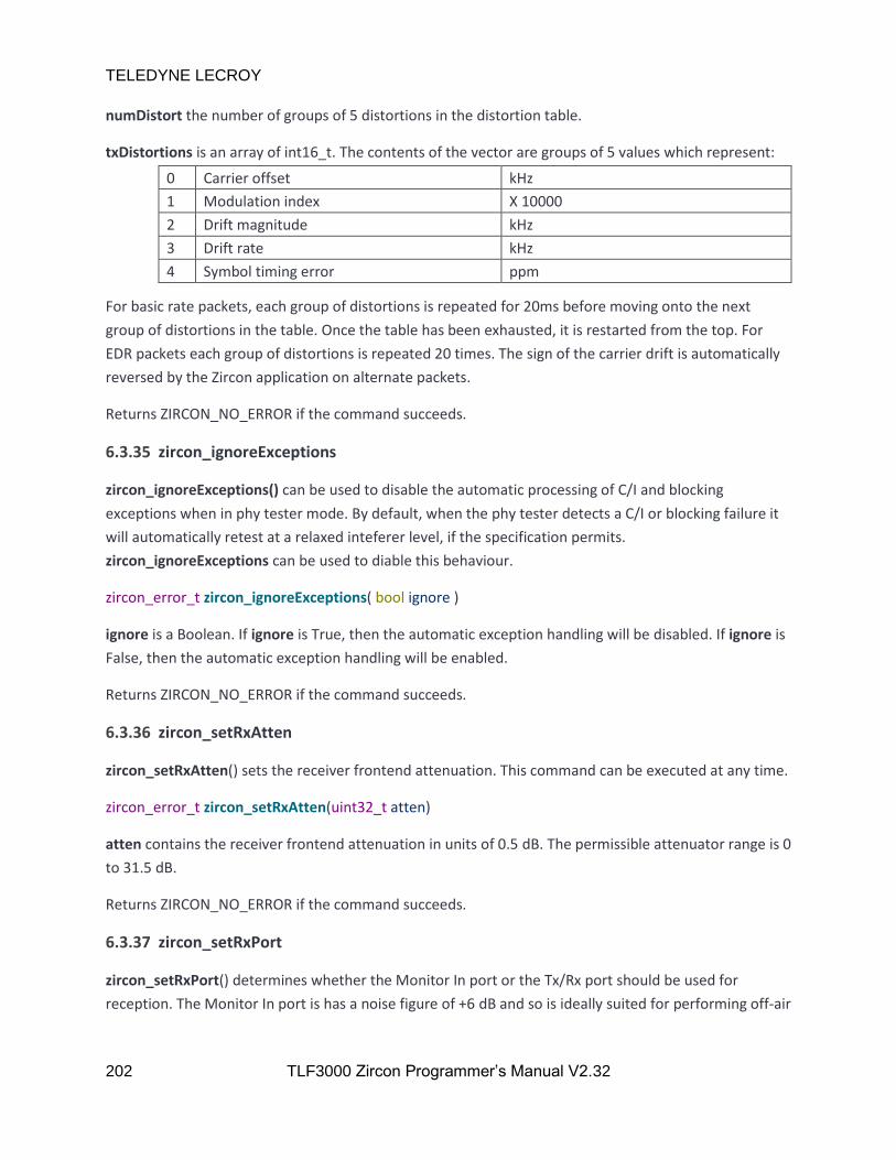
TELEDYNE LECROY
202 TLF3000 Zircon Programmer’s Manual V2.32
numDistort the number of groups of 5 distortions in the distortion table.
txDistortions is an array of int16_t. The contents of the vector are groups of 5 values which represent:
0 Carrier offset kHz
1 Modulation index X 10000
2 Drift magnitude kHz
3 Drift rate kHz
4 Symbol timing error ppm
For basic rate packets, each group of distortions is repeated for 20ms before moving onto the next
group of distortions in the table. Once the table has been exhausted, it is restarted from the top. For
EDR packets each group of distortions is repeated 20 times. The sign of the carrier drift is automatically
reversed by the Zircon application on alternate packets.
Returns ZIRCON_NO_ERROR if the command succeeds.
6.3.35 zircon_ignoreExceptions
zircon_ignoreExceptions() can be used to disable the automatic processing of C/I and blocking
exceptions when in phy tester mode. By default, when the phy tester detects a C/I or blocking failure it
will automatically retest at a relaxed inteferer level, if the specification permits.
zircon_ignoreExceptions can be used to diable this behaviour.
zircon_error_t zircon_ignoreExceptions( bool ignore )
ignore is a Boolean. If ignore is True, then the automatic exception handling will be disabled. If ignore is
False, then the automatic exception handling will be enabled.
Returns ZIRCON_NO_ERROR if the command succeeds.
6.3.36 zircon_setRxAtten
zircon_setRxAtten() sets the receiver frontend attenuation. This command can be executed at any time.
zircon_error_t zircon_setRxAtten(uint32_t atten)
atten contains the receiver frontend attenuation in units of 0.5 dB. The permissible attenuator range is 0
to 31.5 dB.
Returns ZIRCON_NO_ERROR if the command succeeds.
6.3.37 zircon_setRxPort
zircon_setRxPort() determines whether the Monitor In port or the Tx/Rx port should be used for
reception. The Monitor In port is has a noise figure of +6 dB and so is ideally suited for performing off-air

TELEDYNE LECROY
203 TLF3000 Zircon Programmer’s Manual V2.32
measurements. The Tx/Rx port has a noise figure of +46 dB but can handle signals as large as +27 dBm. It
is therefore ideally suited for conducted measurements. This command can be executed at any time.
zircon_error_t zircon_setRxPort(uint32_t port)
port is the receiver port to use for reception and can be one of the following values:
0 Monitor In
1 Tx/Rx port
Returns ZIRCON_NO_ERROR if the command succeeds.
6.3.38 zircon_setDIOVolts
zircon_setDIOVolts() determines whether the digital IO voltage is supplied by TLF3000 or is supplied by
an external source. If TLF3000 supplies the digital IO voltage then it is fixed at 3.3 V. The TLF3000 is able
to provide up to 500 mA on the 3v3 supply. If an external voltage is used for the digital IO then it must
be in the range 0.8 V to 3.6 V. This command can be executed at any time.
zircon_error_t zircon_setDioVolts(bool volts)
volts determines whether the IO voltage is supplied internally or externally:
0 3.3 V IO supplied by TLF3000
1 0.8 V to 3.6 V IO supplied externally
Returns ZIRCON_NO_ERROR if the command succeeds.
6.3.39 zircon_getError
zircon_getError() returns the oldest error message from the Zircon error queue. Once read, this error
message is removed from the error queue.
zircon_error_t zircon_getError( char* err , uint32_t maxlen )
err is a string containing the oldest message of the Zircon error queue. If the queue is empty, then an
empty string is returned.
maxlen is the maximum length of the string which can be returned in err.
Returns ZIRCON_NO_ERROR if the command succeeds.
6.3.40 zircon_search
zircon_search returns a list of the TLF3000 devices connected to the host computer.
zircon_error_t zircon_search(zircon_search_result_t** results, int* N)

TELEDYNE LECROY
204 TLF3000 Zircon Programmer’s Manual V2.32
results is a list of devices which are connected to the host computer. The serial number of each device
can be obtained from results[i].serial_number.
N is the number of devices which have been found.
Returns ZIRCON_NO_ERROR if the command succeeds.
6.3.41 zircon_connect
zircon_connect() connects to a device discovered by zircon_search and launches the Zircon application.
zircon_error_t zircon_connect(zircon_handle_t* handle)
handle is a handle to the device as returned by zircon_search.
Returns ZIRCON_NO_ERROR if the command succeeds.
6.3.42 zircon_disconnect
zircon_disconnect() will cause the Zircon application to exit and control return to the TLF3000
supervistor program,
zircon_error_t zircon_disconnect( void )
Returns ZIRCON_NO_ERROR if the command succeeds.
6.3.43 zircon_search_simple
zircon_search_simple() performs a search for TLF3000 devices and returns the number found. Access to
a device can then be gained via zircon_search_result.
int zircon_search_simple()
Returns the number of TLF3000 devices found.
6.3.44 zircon_search_result
zircon_search_result() returns handle to a TLF3000 discovered by zircon_search_simple. This can then
be used in zircon_connect to connect to the device.
zircon_search_result_t zircon_search_result(int i)
i is the index of the search result to return.
Returns a handle to a TLF3000 device for use in zircon_connect.
6.3.45 zircon_free_search_results
zircon_free_search_results() frees the search results allocated by zircon_search_simple.

TELEDYNE LECROY
205 TLF3000 Zircon Programmer’s Manual V2.32
zircon_error_t zircon_free_search_results()
Returns ZIRCON_NO_ERROR if the command succeeds.
6.3.46 zircon_connect_serial
zircon_connect_serial() searches for a specific TLF3000 device and then connects to it.
zircon_error_t zircon_connect_serial(uint32_t serial_number)
serial_number the serial number of the TLF3000 unit to connect to.
Returns ZIRCON_NO_ERROR if the command succeeds.
6.3.47 zircon_destroy
zircon_destroy() This destructs the DLL internal state. Only for Labview or other applications that
improperly unload the DLL.
void zircon_destroy( void )
6.3.48 zircon_setDataCallback
zircon_setDataCallback adds an asynchronous data callback to the Zircon application. This is used to
report asynchronous data such as test results or the termination of a command.
zircon_error_t zircon_set_data_callback(zircon_data_callback_t cb)
cb the name of the callback to be used.
Returns ZIRCON_NO_ERROR if the command succeeds.
6.3.49 zircon_measure_cw
zircon_measure_cw() instructs the Zircon application to measure the power and frequency of the
strongest in-band CW signal. This can be used to trim the crystal of a DUT on a production line. This
command can only be executed in phy tester mode.
zircon_error_t zircon_measure_cw( double *f , double *p )
f is the frequency of the CW signal in kHz.
p is the power of the CW signal in dBm.
Returns ZIRCON_NO_ERROR if the command succeeds.

TELEDYNE LECROY
206 TLF3000 Zircon Programmer’s Manual V2.32
6.3.50 zircon_testWrapper
zircon_TestWrapper() provides a single call interface to produce a test report.
char *zircon_testWrapper ( uint32_t TLF3000SerialNumber, char *TestScript,
char *TestReport, char *ReportHdr,
uint32_t DUTlap, uint32_t DUTuap, uint32_t DUTnap,
bool rxPort, float rxAtten, uint32_t nLoss,
float *frqs, float *loss, float RSSIthreshold,
uint32_t PageTimeOut, float PagePwr, float LMPpwr,
float PollPwr, bool RunToCompletion,
uint32_t ScriptTimeOut )
TLF3000SerialNumber is the serial number of the TLF3000 unit which will conduct the test.
TestScript is the name of the .sta file which defines the test to be conducted.
TestReport is the name of the file where test results will be placed. The file suffix can be .csv, .txt or
.html. The format of the output file will be governed by the suffix used.
ReportHdr is the name of a file whose contents will be placed at the start of the TestReport file. This
provides a mechanism for customising the test report file. Use a nullptr if no customisation is required.
DUTlap is the Bluetooth LAP address of the device to be tested. If the Bluetooth address is to be found
by the Zircon application performing an inquiry, then set this address to zero.
DUTuap is the Bluetooth UAP address of the device to be tested. If the Bluetooth address is to be found
by the Zircon application performing an inquiry, then set this address to zero.
DUTnap is the Bluetooth NAP address of the device to be tested. If the Bluetooth address is to be found
by the Zircon application performing an inquiry, then set this address to zero.
rxPort is the receiver port to use for reception and can be one of the following values:
0 Monitor In
1 Tx/Rx port
rxAtten is the value of the frontend receiver attenuation to use. Permissible values are in the range 0 to
315dB.
nLoss is the number of points are which the cable loss is defined.
frqs is an array containing the nLoss frequencies at which the cable loss is defined. These must be
monotonic. Units are MHz.
loss is an array containing the nLoss values of the cable loss at the frequencies defined in frqs. Units are
dB.

TELEDYNE LECROY
207 TLF3000 Zircon Programmer’s Manual V2.32
RSSIthreshold is the RSSI threshold for packets. Only packets which are above this threshold will be
analysed by the Zircon application. This can be useful for when the Zircon is finding the DUT via inquiry
since it can be used to ensure only nearby devices are discovered.
PageTimeOut is the time interval permitted for the device connection to be made in units of ms.
PagePwr is the power in dBm of the ID packets transmitted by the Zircon device whilst paging the
device. The Zircon application transmits on all paging channels simultaneously. If the page scan activity
of the DUT is set to ensure the DUT listens frequently, then the connection will be established almost
instantaneously. Because the Zircon application is transmitting on all paging channels simultaneously,
the maximum power per channel is limited to -30dBm.
LMPpwr is the power at which the Zircon application transmits LMP meassges in dBm.
PollPwr is the power at which the Zircon application transmits poll packets in dBm.
RunToCompletion If True, then all tests in the test script file will be executed. If False, then testing will
terminate as soon as a fail condition is detected.
ScriptTimeOut A timeout for performing all the tests in ms.
The call returns a pointer to a character string which will contain “Passed”, “Failed” or an error message.
6.3.51 zircon_testWrapperScalar
zircon_TestWrapperScalar() provides a single call interface to produce a test report. A single cable loss
is specified which is applied to all frequencies.
char *zircon_testWrapperScalar ( uint32_t MorephSerialNumber,
char *TestScript, char *TestReport,
char *ReportHdr, uint32_t DUTlap, uint32_t DUTuap,
uint32_t DUTnap, bool rxPort, float rxAtten,
float cableLoss, float RSSIthreshold,
uint32_t PageTimeOut, float PagePwr, float LMPpwr,
float PollPwr, bool RunToCompletion,
uint32_t ScriptTimeOut )
MorephSerialNumber is the serial number of the Moreph30 unit which will conduct the test.
TestScript is the name of the .sta file which defines the test to be conducted.
TestReport is the name of the file where test results will be placed. The file suffix can be .csv, .txt or
.html. The format of the output file will be governed by the suffix used.
ReportHdr is the name of a file whose contents will be placed at the start of the TestReport file. This
provides a mechanism for customising the test report file. Use a nullptr if no customisation is required.
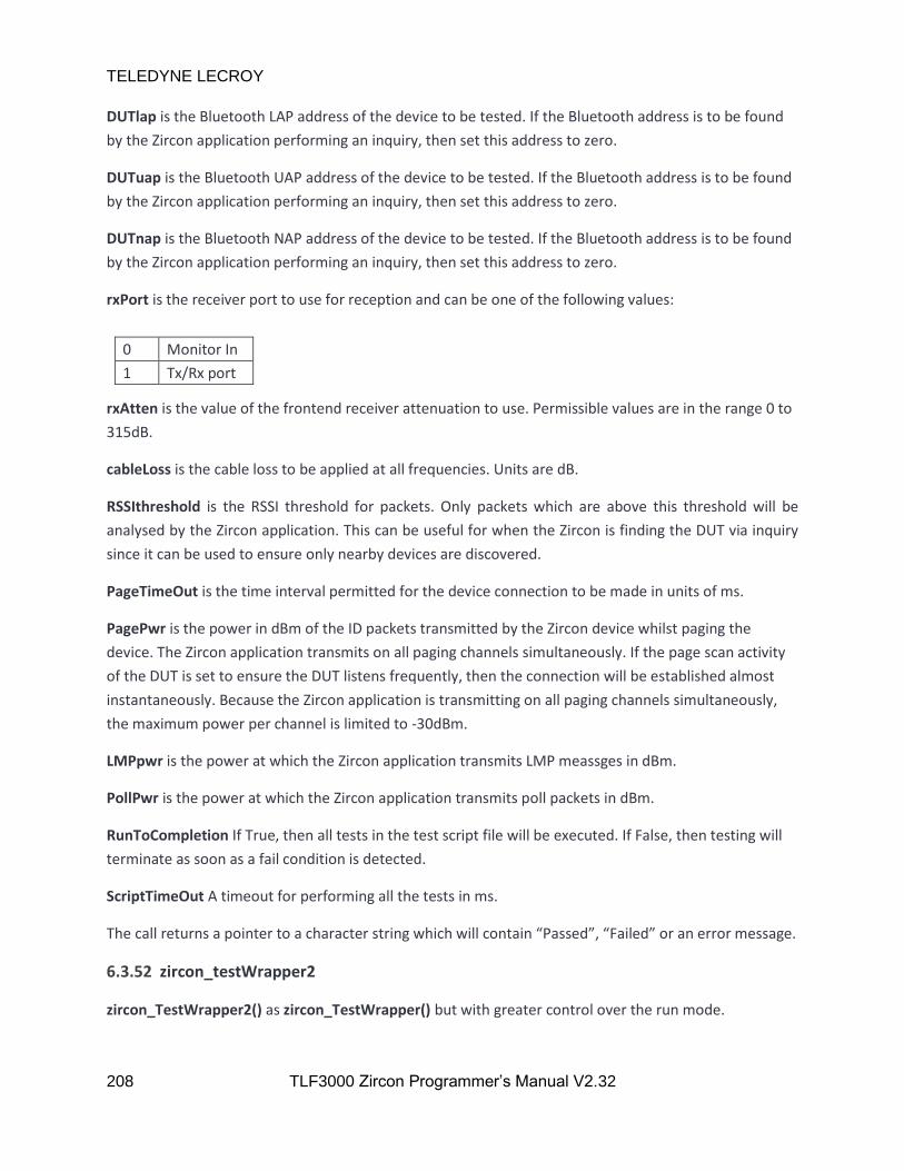
TELEDYNE LECROY
208 TLF3000 Zircon Programmer’s Manual V2.32
DUTlap is the Bluetooth LAP address of the device to be tested. If the Bluetooth address is to be found
by the Zircon application performing an inquiry, then set this address to zero.
DUTuap is the Bluetooth UAP address of the device to be tested. If the Bluetooth address is to be found
by the Zircon application performing an inquiry, then set this address to zero.
DUTnap is the Bluetooth NAP address of the device to be tested. If the Bluetooth address is to be found
by the Zircon application performing an inquiry, then set this address to zero.
rxPort is the receiver port to use for reception and can be one of the following values:
0 Monitor In
1 Tx/Rx port
rxAtten is the value of the frontend receiver attenuation to use. Permissible values are in the range 0 to
315dB.
cableLoss is the cable loss to be applied at all frequencies. Units are dB.
RSSIthreshold is the RSSI threshold for packets. Only packets which are above this threshold will be
analysed by the Zircon application. This can be useful for when the Zircon is finding the DUT via inquiry
since it can be used to ensure only nearby devices are discovered.
PageTimeOut is the time interval permitted for the device connection to be made in units of ms.
PagePwr is the power in dBm of the ID packets transmitted by the Zircon device whilst paging the
device. The Zircon application transmits on all paging channels simultaneously. If the page scan activity
of the DUT is set to ensure the DUT listens frequently, then the connection will be established almost
instantaneously. Because the Zircon application is transmitting on all paging channels simultaneously,
the maximum power per channel is limited to -30dBm.
LMPpwr is the power at which the Zircon application transmits LMP meassges in dBm.
PollPwr is the power at which the Zircon application transmits poll packets in dBm.
RunToCompletion If True, then all tests in the test script file will be executed. If False, then testing will
terminate as soon as a fail condition is detected.
ScriptTimeOut A timeout for performing all the tests in ms.
The call returns a pointer to a character string which will contain “Passed”, “Failed” or an error message.
6.3.52 zircon_testWrapper2
zircon_TestWrapper2() as zircon_TestWrapper() but with greater control over the run mode.
TELEDYNE LECROY
209 TLF3000 Zircon Programmer’s Manual V2.32
char *zircon_testWrapper2( uint32_t MorephSerialNumber, char *TestScript,
char *TestReport, char *ReportHdr,
uint32_t DUTlap, uint32_t DUTuap, uint32_t DUTnap,
bool rxPort, float rxAtten, uint32_t nLoss,
float *frqs, float *loss, float RSSIthreshold,
uint32_t PageTimeOut, float PagePwr, float LMPpwr,
float PollPwr, bool RunToCompletion,
bool onlyLimits, bool noExtra, bool forceLoopback,
uint32_t ScriptTimeOut )
MorephSerialNumber is the serial number of the Moreph30 unit which will conduct the test.
TestScript is the name of the .sta file which defines the test to be conducted.
TestReport is the name of the file where test results will be placed. The file suffix can be .csv, .txt or
.html. The format of the output file will be governed by the suffix used.
ReportHdr is the name of a file whose contents will be placed at the start of the TestReport file. This
provides a mechanism for customising the test report file. Use a nullptr if no customisation is required.
DUTlap is the Bluetooth LAP address of the device to be tested. If the Bluetooth address is to be found
by the Zircon application performing an inquiry, then set this address to zero.
DUTuap is the Bluetooth UAP address of the device to be tested. If the Bluetooth address is to be found
by the Zircon application performing an inquiry, then set this address to zero.
DUTnap is the Bluetooth NAP address of the device to be tested. If the Bluetooth address is to be found
by the Zircon application performing an inquiry, then set this address to zero.
rxPort is the receiver port to use for reception and can be one of the following values:
0 Monitor In
1 Tx/Rx port
rxAtten is the value of the frontend receiver attenuation to use. Permissible values are in the range 0 to
315dB.
nLoss is the number of points are which the cable loss is defined.
frqs is an array containing the nLoss frequencies at which the cable loss is defined. These must be
monotonic. Units are MHz.
loss is an array containing the nLoss values of the cable loss at the frequencies defined in frqs. Units are
dB.
RSSIthreshold is the RSSI threshold for packets. Only packets which are above this threshold will be
analysed by the Zircon application. This can be useful for when the Zircon is finding the DUT via inquiry
since it can be used to ensure only nearby devices are discovered.

TELEDYNE LECROY
210 TLF3000 Zircon Programmer’s Manual V2.32
PageTimeOut is the time interval permitted for the device connection to be made in units of ms.
PagePwr is the power in dBm of the ID packets transmitted by the Zircon device whilst paging the
device. The Zircon application transmits on all paging channels simultaneously. If the page scan activity
of the DUT is set to ensure the DUT listens frequently, then the connection will be established almost
instantaneously. Because the Zircon application is transmitting on all paging channels simultaneously,
the maximum power per channel is limited to -30dBm.
LMPpwr is the power at which the Zircon application transmits LMP meassges in dBm.
PollPwr is the power at which the Zircon application transmits poll packets in dBm.
RunToCompletion If True, then all tests in the test script file will be executed. If False, then testing will
terminate as soon as a fail condition is detected.
onlyLimits is a Boolean. If set, the receiver tests will terminate as soon as sufficient packets have been
sent to determine whether the test will pass or fail the BER limit. This will reduce the accuracy of the
returned BER value but will dramatically reduce test time.
noExtra is a Boolean. By default, when a test is run, if another test uses the identical packet types, then
the results of that test are also calculated in order to save test time. If this parameter is set to True then
this behaviour is stopped.
forceLoopback is a Boolean. By default, transmitter tests are performed using Tx Test mode. If this
parameter is set to True then transmitter tests are performed using loopback mode.
ScriptTimeOut A timeout for performing all the tests in ms.
The call returns a pointer to a character string which will contain “Passed”, “Failed” or an error message.

TELEDYNE LECROY
211 TLF3000 Zircon Programmer’s Manual V2.32
6.3.53 zircon_testWrapperScalar2
zircon_TestWrapperScalar2() as zircon_testWrapperScaler() but with more control over the run mode.
char *zircon_testWrapperScalar2 ( uint32_t MorephSerialNumber,
char *TestScript, char *TestReport,
char *ReportHdr, uint32_t DUTlap, uint32_t DUTuap,
uint32_t DUTnap, bool rxPort, float rxAtten,
float cableLoss, float RSSIthreshold,
uint32_t PageTimeOut, float PagePwr, float LMPpwr,
float PollPwr, bool RunToCompletion,
bool onlyLimits, bool noExtras,
bool forceLoopback, uint32_t ScriptTimeOut )
MorephSerialNumber is the serial number of the Moreph30 unit which will conduct the test.
TestScript is the name of the .sta file which defines the test to be conducted.
TestReport is the name of the file where test results will be placed. The file suffix can be .csv, .txt or
.html. The format of the output file will be governed by the suffix used.
ReportHdr is the name of a file whose contents will be placed at the start of the TestReport file. This
provides a mechanism for customising the test report file. Use a nullptr if no customisation is required.
DUTlap is the Bluetooth LAP address of the device to be tested. If the Bluetooth address is to be found
by the Zircon application performing an inquiry, then set this address to zero.
DUTuap is the Bluetooth UAP address of the device to be tested. If the Bluetooth address is to be found
by the Zircon application performing an inquiry, then set this address to zero.
DUTnap is the Bluetooth NAP address of the device to be tested. If the Bluetooth address is to be found
by the Zircon application performing an inquiry, then set this address to zero.
rxPort is the receiver port to use for reception and can be one of the following values:
0 Monitor In
1 Tx/Rx port
rxAtten is the value of the frontend receiver attenuation to use. Permissible values are in the range 0 to
315dB.
cableLoss is the cable loss to be applied at all frequencies. Units are dB.
RSSIthreshold is the RSSI threshold for packets. Only packets which are above this threshold will be
analysed by the Zircon application. This can be useful for when the Zircon is finding the DUT via inquiry
since it can be used to ensure only nearby devices are discovered.

TELEDYNE LECROY
212 TLF3000 Zircon Programmer’s Manual V2.32
PageTimeOut is the time interval permitted for the device connection to be made in units of ms.
PagePwr is the power in dBm of the ID packets transmitted by the Zircon device whilst paging the
device. The Zircon application transmits on all paging channels simultaneously. If the page scan activity
of the DUT is set to ensure the DUT listens frequently, then the connection will be established almost
instantaneously. Because the Zircon application is transmitting on all paging channels simultaneously,
the maximum power per channel is limited to -30dBm.
LMPpwr is the power at which the Zircon application transmits LMP meassges in dBm.
PollPwr is the power at which the Zircon application transmits poll packets in dBm.
RunToCompletion If True, then all tests in the test script file will be executed. If False, then testing will
terminate as soon as a fail condition is detected.
onlyLimits is a Boolean. If set, the receiver tests will terminate as soon as sufficient packets have been
sent to determine whether the test will pass or fail the BER limit. This will reduce the accuracy of the
returned BER value but will dramatically reduce test time.
noExtra is a Boolean. By default, when a test is run, if another test uses the identical packet types, then
the results of that test are also calculated in order to save test time. If this parameter is set to True then
this behaviour is stopped.
forceLoopback is a Boolean. By default, transmitter tests are performed using Tx Test mode. If this
parameter is set to True then transmitter tests are performed using loopback mode.
ScriptTimeOut A timeout for performing all the tests in ms.
The call returns a pointer to a character string which will contain “Passed”, “Failed” or an error message.
6.3.54 zircon_testWrapper_CW
zircon_testWrapper_CW() provides a single call interface to make a CW measurement.
char *zircon_testWrapper_CW ( uint32_t TLF3000SerialNumber, bool rxPort,
float rxAtten, uint32_t nLoss, float *frqs,
float *loss, double *f, double *p )
TLF3000SerialNumber is the serial number of the TLF3000 unit which will conduct the test.
rxPort is the receiver port to use for reception and can be one of the following values:
0 Monitor In
1 Tx/Rx port
rxAtten is the value of the frontend receiver attenuation to use. Permissible values are in the range 0 to
315dB.

TELEDYNE LECROY
213 TLF3000 Zircon Programmer’s Manual V2.32
nLoss is the number of points are which the cable loss is defined.
frqs is an array containing the nLoss frequencies at which the cable loss is defined. These must be
monotonic. Units are MHz.
loss is an array containing the nLoss values of the cable loss at the frequencies defined in frqs. Units are
dB.
f points to a double which will receive the frequency of the CW signal in kHz.
p points to a double which will receive the power of the CW signal in dBm.
6.3.55 zircon_hardwareReset
zircon_hardwareReset() will cause the TLF3000 to reboot.
zircon_error_t zircon_hardwareReset( void )
6.3.56 zircon_powerDown
zircon_powerDown() will power down the TLF3000.
zircon_error_t zircon_PowerDown( void )
6.3.57 zircon_getFriendlyName
zircon_getFriendlyName() will return the friendly name of the TLF3000 unit.
zircon_error_t zircon_friendly_name(char* name, unsigned maxlen)
name is a string containging the friendly name of the TLF3000 unit.
maxlen is the maximum length of the string which can be returned in name.
Returns ZIRCON_NO_ERROR if the command succeeds.
6.3.58 zircon_getSerialNumber
zircon_getSerialNumber() will return the serial number of the TLF3000 unit.
zircon_error_t zircon_getSerialNumber(uint32_t* serial)
serial is an integer containing the serial number of the TLF3000 unit.
Returns ZIRCON_NO_ERROR if the command succeeds.

TELEDYNE LECROY
214 TLF3000 Zircon Programmer’s Manual V2.32
6.3.59 zircon_stashExe
zircon_stashExe() instructs the TLF3000 to place the Zircon image into RAM disc so that it can be quickly
retrieved after another application has been run.
zircon_error_t zircon_stashExe(void)
Returns ZIRCON_NO_ERROR if the command succeeds.
6.3.60 zircon_swapExe
zircon_swapExe() tells Zircon which application is going to be run next on the TLF3000. This application
will be started when the Zircon application is suspended.
zircon_error_t zircon_swapExe(unsigned int num)
num is the application number of the next application to be run.
Returns ZIRCON_NO_ERROR if the command succeeds.
6.3.61 zircon_suspend
zircon_suspend() suspends execution of the Zircon application and changes execution to the application
specified in the last zircon_swapExc() command.
zircon_error_t zircon_suspend(void)
Returns ZIRCON_NO_ERROR if the command succeeds.
6.3.62 zircon_resume
zircon_resume() should be called after another application has swapped execution to the Zircon
application. This causes the resumption of the Zircon application.
zircon_error_t zircon_resume(void)
Returns ZIRCON_NO_ERROR if the command succeeds.

TELEDYNE LECROY
215 TLF3000 Zircon Programmer’s Manual V2.32
7 Test Script Format
7.1 Overview
When running in phy level test mode, the tests which are performed are specified via a test script. A test
script is a named ASCII file which is downloaded to the Zircon application. Multiple test scripts can reside
within the Zircon application simultaneously. These test scripts can reside in either RAM or FLASH (not
currently implemented). Test scripts residing in RAM will be lost when the unit is powered down. Test
scripts held in FLASH will persist between power cycles of the unit.
7.2 General Format
Test scripts are held as ASCII files. The test script is case insensitive. There should be no whitespace
within the test script.
Each line within the file represents a new test to be run. This is composed of:
1. A test header to indicate which test is to be run
2. A test body to indicate the parameters for that test
The test header and test body are separated by the character ‘,’.
Fields within the test body are separated by the character ‘,’.
Fields which contain lists should be of the form element 1, element 2, …. .
7.3 Test header
The first 3 letters of each line must be either:
1. ‘TRM’ to represent a transmitter test
2. ‘RCV’ to represent a receiver test

TELEDYNE LECROY
216 TLF3000 Zircon Programmer’s Manual V2.32
Immediately following the transmit/receive letters is a test number to indicate which test should be
performed. The values for transmitter tests (TRM) are:
Test number Test description
1 Output power
2 Power density
3 Power control
4 Tx output spectrum – frequency range
5 Tx output spectrum – 20dB bandwidth
6 Tx output spectrum – adjacent channel power
7 Modulation characteristics
8 Initial carrier frequency tolerance
9 Carrier frequency drift
10 EDR relative transmit power
11 EDR carrier frequency stability and modulation accuracy
12 EDR differential phase encoding
13 EDR in-band spurious emissions
14 Enhanced power control
15 EDR guard time
16 EDR synchronisation sequence and trailer
And for receiver tests (RCV):
Test number Test description
1 Sensitivity – singe slot packets
2 Sensitivity – multi slot packets
3 C/I performance
4 Blocking performance
5 Intermodulation performance
6 Maximum input level
7 EDR sensitivity
8 EDR BER floor performance
9 EDR C/I performance
10 EDR maximum input level
The format of the remainder of the test script line depends on which test has been specified.
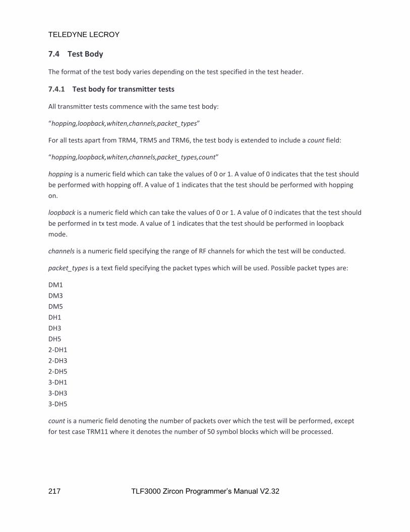
TELEDYNE LECROY
217 TLF3000 Zircon Programmer’s Manual V2.32
7.4 Test Body
The format of the test body varies depending on the test specified in the test header.
7.4.1 Test body for transmitter tests
All transmitter tests commence with the same test body:
“hopping,loopback,whiten,channels,packet_types”
For all tests apart from TRM4, TRM5 and TRM6, the test body is extended to include a count field:
“hopping,loopback,whiten,channels,packet_types,count”
hopping is a numeric field which can take the values of 0 or 1. A value of 0 indicates that the test should
be performed with hopping off. A value of 1 indicates that the test should be performed with hopping
on.
loopback is a numeric field which can take the values of 0 or 1. A value of 0 indicates that the test should
be performed in tx test mode. A value of 1 indicates that the test should be performed in loopback
mode.
channels is a numeric field specifying the range of RF channels for which the test will be conducted.
packet_types is a text field specifying the packet types which will be used. Possible packet types are:
DM1
DM3
DM5
DH1
DH3
DH5
2-DH1
2-DH3
2-DH5
3-DH1
3-DH3
3-DH5
count is a numeric field denoting the number of packets over which the test will be performed, except
for test case TRM11 where it denotes the number of 50 symbol blocks which will be processed.
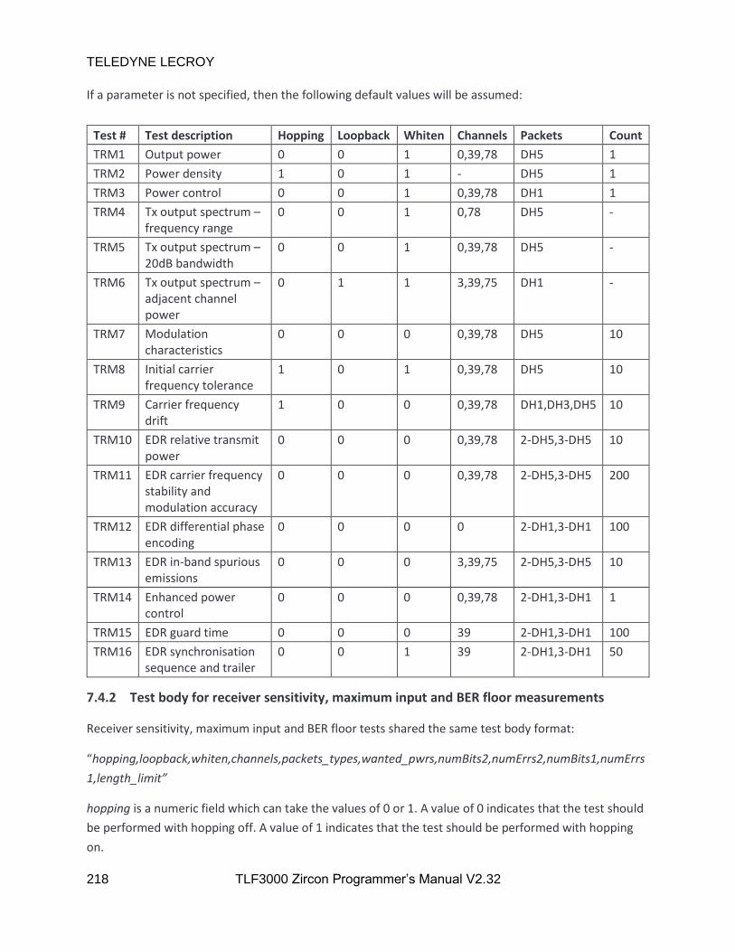
TELEDYNE LECROY
218 TLF3000 Zircon Programmer’s Manual V2.32
If a parameter is not specified, then the following default values will be assumed:
Test # Test description Hopping Loopback Whiten Channels Packets Count
TRM1 Output power 0 0 1 0,39,78 DH5 1
TRM2 Power density 1 0 1 - DH5 1
TRM3 Power control 0 0 1 0,39,78 DH1 1
TRM4 Tx output spectrum – frequency range
0 0 1 0,78 DH5 -
TRM5 Tx output spectrum – 20dB bandwidth
0 0 1 0,39,78 DH5 -
TRM6 Tx output spectrum – adjacent channel power
0 1 1 3,39,75 DH1 -
TRM7 Modulation characteristics
0 0 0 0,39,78 DH5 10
TRM8 Initial carrier frequency tolerance
1 0 1 0,39,78 DH5 10
TRM9 Carrier frequency drift
1 0 0 0,39,78 DH1,DH3,DH5 10
TRM10 EDR relative transmit power
0 0 0 0,39,78 2-DH5,3-DH5 10
TRM11 EDR carrier frequency stability and modulation accuracy
0 0 0 0,39,78 2-DH5,3-DH5 200
TRM12 EDR differential phase encoding
0 0 0 0 2-DH1,3-DH1 100
TRM13 EDR in-band spurious emissions
0 0 0 3,39,75 2-DH5,3-DH5 10
TRM14 Enhanced power control
0 0 0 0,39,78 2-DH1,3-DH1 1
TRM15 EDR guard time 0 0 0 39 2-DH1,3-DH1 100
TRM16 EDR synchronisation sequence and trailer
0 0 1 39 2-DH1,3-DH1 50
7.4.2 Test body for receiver sensitivity, maximum input and BER floor measurements
Receiver sensitivity, maximum input and BER floor tests shared the same test body format:
“hopping,loopback,whiten,channels,packets_types,wanted_pwrs,numBits2,numErrs2,numBits1,numErrs
1,length_limit”
hopping is a numeric field which can take the values of 0 or 1. A value of 0 indicates that the test should
be performed with hopping off. A value of 1 indicates that the test should be performed with hopping
on.

TELEDYNE LECROY
219 TLF3000 Zircon Programmer’s Manual V2.32
loopback is a numeric field which can take the values of 0 or 1. A value of 0 indicates that the test should
be performed in tx test mode. A value of 1 indicates that the test should be performed in loopback
mode. All receiver tests must be performed in loopback mode.
channels is a numeric field specifying the range of RF channels for which the test will be conducted.
packet_types is a text field specifying the packet types which will be used. Possible packet types are:
DM1
DM3
DM5
DH1
DH3
DH5
2-DH1
2-DH3
2-DH5
3-DH1
3-DH3
3-DH5
wanted_pwrs is a numeric field specifying the wanted signal level powers over which the test will be
conducted in units of dBm.
If any of the above parameters are not specified, then the values in the table below are assumed:
Test # Test description Hopping Loopback Whiten Channels Packets Power
RCV1 Sensitivity – singe slot packets
0 1 1 0,39,78 DH1 -70
RCV2 Sensitivity – multi slot packets
0 1 1 0,39,78 DH5 -70
RCV6 Maximum input level 0 1 1 3,39,75 DH1 -20
RCV7 EDR sensitivity 0 1 1 0,39,78 2-DH5,3-DH5 -70
RCV8 EDR BER floor performance
0 1 1 0,39,78 2-DH5,3-DH5 -60
RCV10 EDR maximum input level
0 1 1 0,39,78 2-DH5,3-DH5 -20
numBits2 is a numeric field containing the number of bits to be tested.
numErrs2 is a numeric field containing the permissible bit error rate.
numBits1 is a numeric field containing the number of bits to be tested for early exit.
numErrs1 is a numeric field containing the permissible bit error rate for early exit.
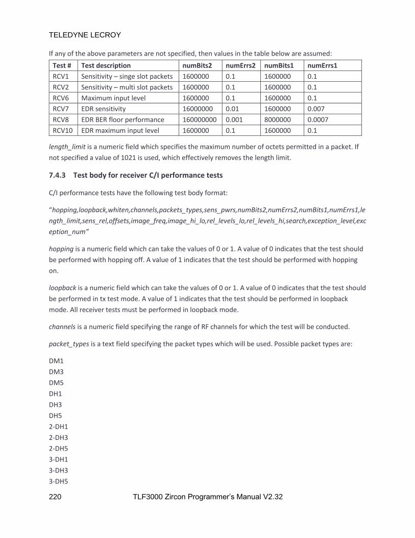
TELEDYNE LECROY
220 TLF3000 Zircon Programmer’s Manual V2.32
If any of the above parameters are not specified, then values in the table below are assumed:
Test # Test description numBits2 numErrs2 numBits1 numErrs1
RCV1 Sensitivity – singe slot packets 1600000 0.1 1600000 0.1
RCV2 Sensitivity – multi slot packets 1600000 0.1 1600000 0.1
RCV6 Maximum input level 1600000 0.1 1600000 0.1
RCV7 EDR sensitivity 16000000 0.01 1600000 0.007
RCV8 EDR BER floor performance 160000000 0.001 8000000 0.0007
RCV10 EDR maximum input level 1600000 0.1 1600000 0.1
length_limit is a numeric field which specifies the maximum number of octets permitted in a packet. If
not specified a value of 1021 is used, which effectively removes the length limit.
7.4.3 Test body for receiver C/I performance tests
C/I performance tests have the following test body format:
“hopping,loopback,whiten,channels,packets_types,sens_pwrs,numBits2,numErrs2,numBits1,numErrs1,le
ngth_limit,sens_rel,offsets,image_freq,image_hi_lo,rel_levels_lo,rel_levels_hi,search,exception_level,exc
eption_num”
hopping is a numeric field which can take the values of 0 or 1. A value of 0 indicates that the test should
be performed with hopping off. A value of 1 indicates that the test should be performed with hopping
on.
loopback is a numeric field which can take the values of 0 or 1. A value of 0 indicates that the test should
be performed in tx test mode. A value of 1 indicates that the test should be performed in loopback
mode. All receiver tests must be performed in loopback mode.
channels is a numeric field specifying the range of RF channels for which the test will be conducted.
packet_types is a text field specifying the packet types which will be used. Possible packet types are:
DM1
DM3
DM5
DH1
DH3
DH5
2-DH1
2-DH3
2-DH5
3-DH1
3-DH3
3-DH5
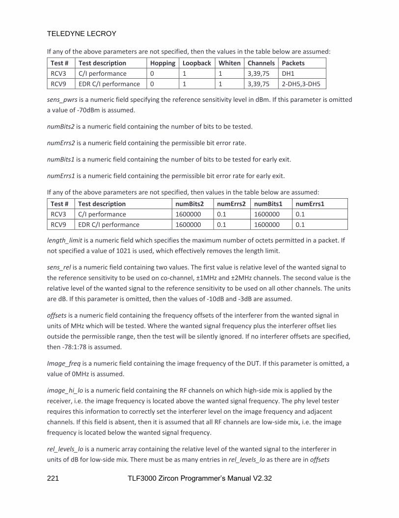
TELEDYNE LECROY
221 TLF3000 Zircon Programmer’s Manual V2.32
If any of the above parameters are not specified, then the values in the table below are assumed:
Test # Test description Hopping Loopback Whiten Channels Packets
RCV3 C/I performance 0 1 1 3,39,75 DH1
RCV9 EDR C/I performance 0 1 1 3,39,75 2-DH5,3-DH5
sens_pwrs is a numeric field specifying the reference sensitivity level in dBm. If this parameter is omitted
a value of -70dBm is assumed.
numBits2 is a numeric field containing the number of bits to be tested.
numErrs2 is a numeric field containing the permissible bit error rate.
numBits1 is a numeric field containing the number of bits to be tested for early exit.
numErrs1 is a numeric field containing the permissible bit error rate for early exit.
If any of the above parameters are not specified, then values in the table below are assumed:
Test # Test description numBits2 numErrs2 numBits1 numErrs1
RCV3 C/I performance 1600000 0.1 1600000 0.1
RCV9 EDR C/I performance 1600000 0.1 1600000 0.1
length_limit is a numeric field which specifies the maximum number of octets permitted in a packet. If
not specified a value of 1021 is used, which effectively removes the length limit.
sens_rel is a numeric field containing two values. The first value is relative level of the wanted signal to
the reference sensitivity to be used on co-channel, ±1MHz and ±2MHz channels. The second value is the
relative level of the wanted signal to the reference sensitivity to be used on all other channels. The units
are dB. If this parameter is omitted, then the values of -10dB and -3dB are assumed.
offsets is a numeric field containing the frequency offsets of the interferer from the wanted signal in
units of MHz which will be tested. Where the wanted signal frequency plus the interferer offset lies
outside the permissible range, then the test will be silently ignored. If no interferer offsets are specified,
then -78:1:78 is assumed.
Image_freq is a numeric field containing the image frequency of the DUT. If this parameter is omitted, a
value of 0MHz is assumed.
image_hi_lo is a numeric field containing the RF channels on which high-side mix is applied by the
receiver, i.e. the image frequency is located above the wanted signal frequency. The phy level tester
requires this information to correctly set the interferer level on the image frequency and adjacent
channels. If this field is absent, then it is assumed that all RF channels are low-side mix, i.e. the image
frequency is located below the wanted signal frequency.
rel_levels_lo is a numeric array containing the relative level of the wanted signal to the interferer in
units of dB for low-side mix. There must be as many entries in rel_levels_lo as there are in offsets

TELEDYNE LECROY
222 TLF3000 Zircon Programmer’s Manual V2.32
rel_levels_hi is a numeric array containing the relative level of the wanted signal to the interferer in
units of dB for high-side mix. There must be as many entries in rel_levels_hi as there are in offsets
search is a numeric field containing the range of interferer levels to test over in units of dB. The nominal
interferer level is set by the wanted signal level minus the C/I level. However, the phy lvl tester can
further vary the interferer level by addition of the values specified in the search range. This provides a
means of determining the ultimate C/I performance of a device for a given wanted signal level. If no
search range is specified, then a default value of 0 dB is assumed.
exception_level is the C/I level in dB at which a channel should be retested if it fails and if an exception is
permitted. If this parameter is omitted, a value of -17dB is assumed for basic rate packets, -15dB for 2-
EDR packets and -10dB for 3-EDR packets.
exception_num is the number of permitted C/I exceptions. If this parameter is omitted, a value of 5 is
assumed.
7.4.4 Test body for receiver blocking tests
Receiver blocking tests have a test body in the form:
“hopping,loopback,whiten,channels,packets_types,wanted_pwrs,numBits2,numErrs2,numBits1,numErrs
1,length_limit,sens_rel,blocker_freqs,blocker_levels,search,exception_level,exception_num,fail_num”
hopping is a numeric field which can take the values of 0 or 1. A value of 0 indicates that the test should
be performed with hopping off. A value of 1 indicates that the test should be performed with hopping
on.
loopback is a numeric field which can take the values of 0 or 1. A value of 0 indicates that the test should
be performed in tx test mode. A value of 1 indicates that the test should be performed in loopback
mode. All receiver tests must be performed in loopback mode.
channels is a numeric field specifying the range of RF channels for which the test will be conducted.
packet_types is a text field specifying the packet types which will be used. Possible packet types are:
DM1
DM3
DM5
DH1
DH3
DH5
2-DH1
2-DH3
2-DH5
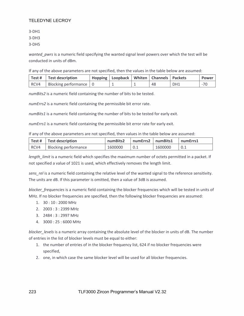
TELEDYNE LECROY
223 TLF3000 Zircon Programmer’s Manual V2.32
3-DH1
3-DH3
3-DH5
wanted_pwrs is a numeric field specifying the wanted signal level powers over which the test will be
conducted in units of dBm.
If any of the above parameters are not specified, then the values in the table below are assumed:
Test # Test description Hopping Loopback Whiten Channels Packets Power
RCV4 Blocking performance 0 1 1 48 DH1 -70
numBits2 is a numeric field containing the number of bits to be tested.
numErrs2 is a numeric field containing the permissible bit error rate.
numBits1 is a numeric field containing the number of bits to be tested for early exit.
numErrs1 is a numeric field containing the permissible bit error rate for early exit.
If any of the above parameters are not specified, then values in the table below are assumed:
Test # Test description numBits2 numErrs2 numBits1 numErrs1
RCV4 Blocking performance 1600000 0.1 1600000 0.1
length_limit is a numeric field which specifies the maximum number of octets permitted in a packet. If
not specified a value of 1021 is used, which effectively removes the length limit.
sens_rel is a numeric field containing the relative level of the wanted signal to the reference sensitivity.
The units are dB. If this parameter is omitted, then a value of 3dB is assumed.
blocker_frequencies is a numeric field containing the blocker frequencies which will be tested in units of
MHz. If no blocker frequencies are specified, then the following blocker frequencies are assumed:
1. 30 : 10 : 2000 MHz
2. 2003 : 3 : 2399 MHz
3. 2484 : 3 : 2997 MHz
4. 3000 : 25 : 6000 MHz
blocker_levels is a numeric array containing the absolute level of the blocker in units of dB. The number
of entries in the list of blocker levels must be equal to either:
1. the number of entries of in the blocker frequency list, 624 if no blocker frequencies were
specified,
2. one, in which case the same blocker level will be used for all blocker frequencies.

TELEDYNE LECROY
224 TLF3000 Zircon Programmer’s Manual V2.32
If no blocker levels are specified, then the following assumptions are made:
< 2000 MHz 2000-2399 MHz 2484-2999 MHz >= 3000 MHz
-30 dBm -35 dBm -35 dBm -30 dBm
search is a numeric field containing the range of blocker levels to test over in units of dB. The nominal
blocker level is set by the blocker level field, however, the phy lvl tester can further vary the blocker
level by addition of the values specified in the search range. This provides a means of determining the
ultimate blocking performance of a device for a given wanted signal level. If no search range is specified,
then a default value of 0 dB is assumed.
exception_level is the blocker level in dBm at which a channel should be retested if it fails. If this
parameter is omitted a value of -50dBm is assumed.
exception_num is the number of permitted blocker exceptions. If this parameter is omitted a value of 24
is assumed.
fail_num is the number of failures permitted at the exception level. If this parameter is omitted a value
of 5 is assumed.
7.4.5 Test body for receiver intermodulation tests
Receiver intermodulation tests have a test body in the form:
“hopping,loopback,whiten,channels,packets_types,wanted_pwrs,numBits2,numErrs2,numBits1,numErrs
1,length_limit,sens_rel,intermod_n,intermod_pwrs”
hopping is a numeric field which can take the values of 0 or 1. A value of 0 indicates that the test should
be performed with hopping off. A value of 1 indicates that the test should be performed with hopping
on.
loopback is a numeric field which can take the values of 0 or 1. A value of 0 indicates that the test should
be performed in tx test mode. A value of 1 indicates that the test should be performed in loopback
mode. All receiver tests must be performed in loopback mode.
channels is a numeric field specifying the range of RF channels for which the test will be conducted.
packet_types is a text field specifying the packet types which will be used. Possible packet types are:
DM1
DM3
DM5
DH1
DH3
DH5

TELEDYNE LECROY
225 TLF3000 Zircon Programmer’s Manual V2.32
2-DH1
2-DH3
2-DH5
3-DH1
3-DH3
3-DH5
wanted_pwrs is a numeric field specifying the wanted signal level powers over which the test will be
conducted in units of dBm.
If any of the above parameters are not specified, then the values in the table below are assumed:
Test # Test description Hopping Loopback Whiten Channels Packets Power
RCV5 Intermodulation performance
0 1 1 0,39,78 DH1 -70
numBits2 is a numeric field containing the number of bits to be tested.
numErrs2 is a numeric field containing the permissible bit error rate.
numBits1 is a numeric field containing the number of bits to be tested for early exit.
numErrs1 is a numeric field containing the permissible bit error rate for early exit.
If any of the above parameters are not specified, then values in the table below are assumed:
Test # Test description numBits2 numErrs2 numBits1 numErrs1
RCV5 Intermodulation performance 1600000 0.1 1600000 0.1
length_limit is a numeric field which specifies the maximum number of octets permitted in a packet. If
not specified a value of 1021 is used, which effectively removes the length limit.
sens_rel is a numeric field containing the relative level of the wanted signal to the reference sensitivity.
The units are dB. If this parameter is omitted, then a value of 6dB is assumed.
Intermod_N is a numeric field containing the separation of the two interfering signals. This is in units of
1 MHz. If no separation of the two interfering signals is specified, then a default value of 3 is assumed.
intermod_levels is a numeric array containing the absolute levels of the two interferer signals in units of
dBm. The two interferer signals will always have the same amplitude. If no interferer levels are specified,
then a default value of -39 dBm is assumed.

TELEDYNE LECROY
226 TLF3000 Zircon Programmer’s Manual V2.32
8 Connectors.
8.1 Front Panel
8.1.1 Monitor In Port
Function High sensitivity 2.4 GHz RF input Suitable for radiated measurements
Connector type SMA
Noise figure 6 dB typ
IP3 @ max sensitivity +7 dBm typ
SNR in 1MHz bandwidth 80 dB typ
Maximum input signal 27 dBm
Maximum usable signal -10 dBm typ
Frequency range 2401-2481 MHz
Impedance 50 Ω
Coupling AC
Maximum DC voltage 50 V
8.1.2 Tx/Rx port
Function Low sensitivity 2.4GHz RF input and signal generator output Suitable for conducted measurements
Connector type SMA
Impedance 50 Ω
Coupling AC
Maximum DC voltage 50 V
8.1.3 Receiver Specification
Noise figure 46 dB typ
IP3 @ max sensitivity +47 dBm typ
SNR in 1MHz bandwidth 80 dB typ
Maximum input signal 27 dBm
Maximum usable signal 27 dBm typ
Frequency range 2401-2481 MHz

TELEDYNE LECROY
227 TLF3000 Zircon Programmer’s Manual V2.32
8.1.4 Video port
Function Not used in Zircon application
Connector type SMA
Impedance 50 Ω
Coupling AC
Maximum DC voltage 5 V
8.1.5 External Clock Input
Function External clock input Permits internal RF, sampling and timestamp clocks to be locked to an external reference
Connector type SMA
Maximum input signal -10 dBm
Minimum input signal +20 dBm
Frequency range 10 MHz
Impedance 50 Ω
Coupling AC
Maximum DC voltage 50 V
8.1.6 Reference Clock Output
Function Reference clock output Provides a reference clock which can be used to synchronise other test equipment
Connector type SMA
Output signal -2 dBm
Frequency 10 MHz
Impedance 50 Ω
Coupling AC
Maximum DC voltage 5 V
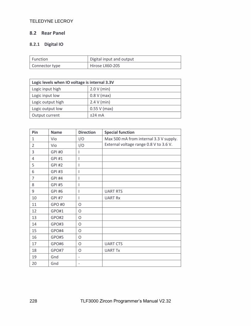
TELEDYNE LECROY
228 TLF3000 Zircon Programmer’s Manual V2.32
8.2 Rear Panel
8.2.1 Digital IO
Function Digital input and output
Connector type Hirose LX60-20S
Logic levels when IO voltage is internal 3.3V
Logic input high 2.0 V (min)
Logic input low 0.8 V (max)
Logic output high 2.4 V (min)
Logic output low 0.55 V (max)
Output current ±24 mA
Pin Name Direction Special function
1 Vio I/O Max 500 mA from internal 3.3 V supply. External voltage range 0.8 V to 3.6 V. 2 Vio I/O
3 GPI #0 I
4 GPI #1 I
5 GPI #2 I
6 GPI #3 I
7 GPI #4 I
8 GPI #5 I
9 GPI #6 I UART RTS
10 GPI #7 I UART Rx
11 GPO #0 O
12 GPO#1 O
13 GPO#2 O
14 GPO#3 O
15 GPO#4 O
16 GPO#5 O
17 GPO#6 O UART CTS
18 GPO#7 O UART Tx
19 Gnd -
20 Gnd -

TELEDYNE LECROY
229 TLF3000 Zircon Programmer’s Manual V2.32
8.2.2 USB Connector
Function USB connection to host
Connector type Micro-USB
Speed rating High speed
VBUS load 2.2 µF, > 10 kΩ
8.2.3 Ethernet Connector
Function Ethernet connection to host
Connector type RJ45
Speed 10 / 100 / 1000
8.2.4 Power Connector~
Function DC power input
Connector type 2.5 mm jack
Input voltage 12 V DC
Power 10 W typ (application dependent)
Reverse polarity protection Yes
Over voltage protection Yes
Under voltage protection Yes
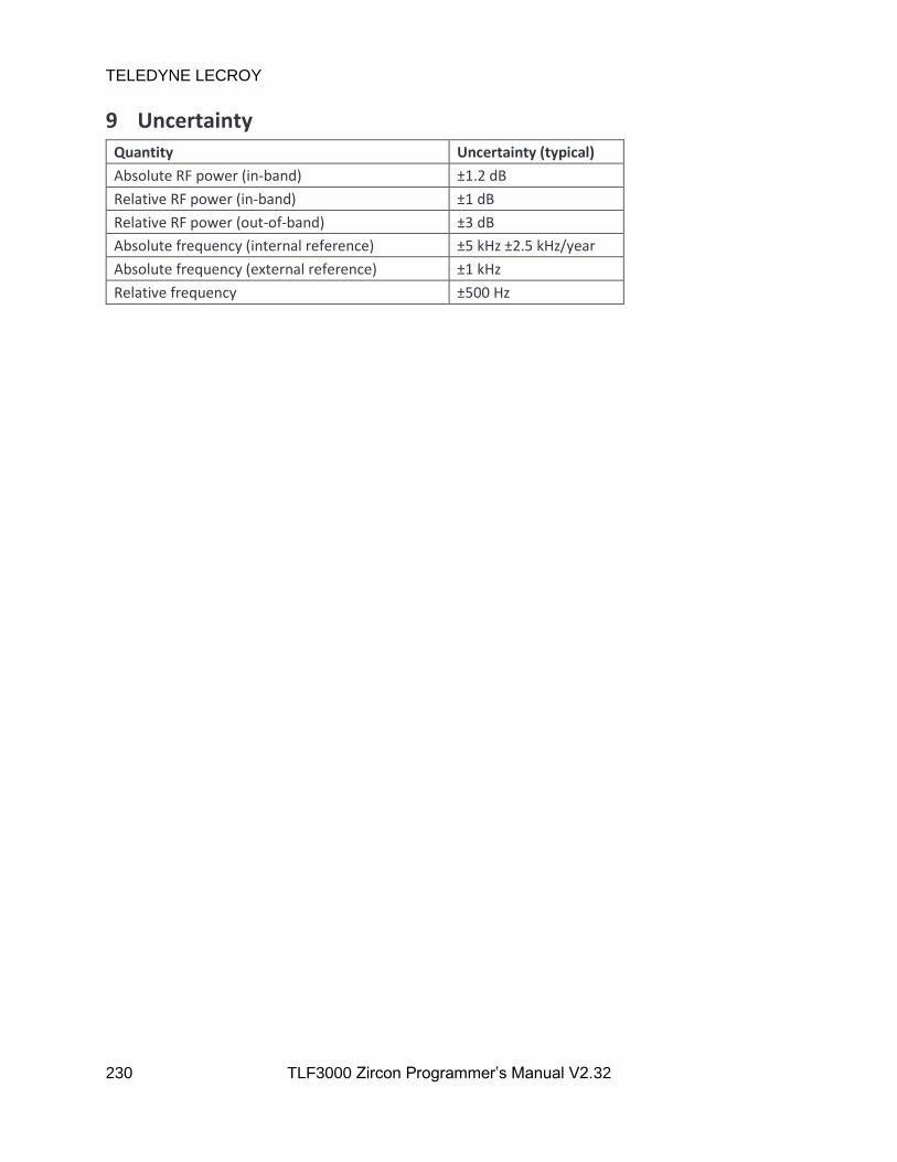
TELEDYNE LECROY
230 TLF3000 Zircon Programmer’s Manual V2.32
9 Uncertainty
Quantity Uncertainty (typical)
Absolute RF power (in-band) ±1.2 dB
Relative RF power (in-band) ±1 dB
Relative RF power (out-of-band) ±3 dB
Absolute frequency (internal reference) ±5 kHz ±2.5 kHz/year
Absolute frequency (external reference) ±1 kHz
Relative frequency ±500 Hz
TELEDYNE LECROY
231 TLF3000 Zircon Programmer’s Manual V2.32
10 Indicators
10.1 Front Panel
10.1.1 Status
The right hand LED indicates the status of the unit. When power is applied this will light YELLOW
indicating that the internal power supplies are good. Once the unit has booted and is ready for host
commands it will turn GREEN.
10.1.2 RF Overload
The left hand LED indicates whether an RF overload is present. The RF overload may be either on a
receiver input or the signal generator output. The Input/Output Power messages can provide further
details on the source of the overload.
The both the Monitor In port and the Tx/Rx port are protected for input signals up to a maximum level
of 27 dB. Input signals beyond this will destroy the unit. If a receive overload condition is present, the
results of the unit are uncertain. If the Monitor In port is in use, then swapping to the less sensitive
Tx/Rx port may alleviate the RF overload condition.
10.1.3 Flash Update
When the Flash is being updated, the Status LED flash will flash between YELLOW and RED. Do not
remove power from the unit whilst the Flash is being updated.


