
External Use
TM
Wireless Charging Solutions
EUF-IND-T0590
J U N E . 2 0 1 4
Pavel Michlicek
TM
External Use 1
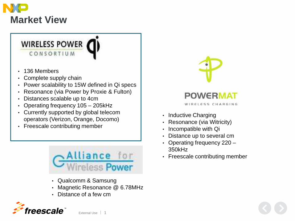
• 136 Members
• Complete supply chain
• Power scalability to 15W defined in Qi specs
• Resonance (via Power by Proxie & Fulton)
• Distances scalable up to 4cm
• Operating frequency 105 – 205kHz
• Currently supported by global telecom
operators (Verizon, Orange, Docomo)
• Freescale contributing member
• Inductive Charging
• Resonance (via Witricity)
• Incompatible with Qi
• Distance up to several cm
• Operating frequency 220 –
350kHz
• Freescale contributing member
• Qualcomm & Samsung
• Magnetic Resonance @ 6.78MHz
• Distance of a few cm
Market View

TM
External Use 2
• 136 Members
• Complete supply chain
• Power scalability to 15W defined in Qi
specs
• Resonance (via Power by Proxie & Fulton)
• Distances scalable up to 4cm
• Operating frequency 105 – 205kHz
• Currently supported by global telecom
operators (Verizon, Orange, Docomo)
• Freescale contributing member
• Inductive Charging
• Resonance (via Witricity)
• Incompatible with Qi
• Distance up to several cm
• Operating frequency 220 –
350kHz
• Freescale contributing member
• Qualcomm & Samsung
• Magnetic Resonance @ 6.78MHz
• Distance of a few cm
FSL
Certified
FSL
Supported
Market View
TM
External Use 3
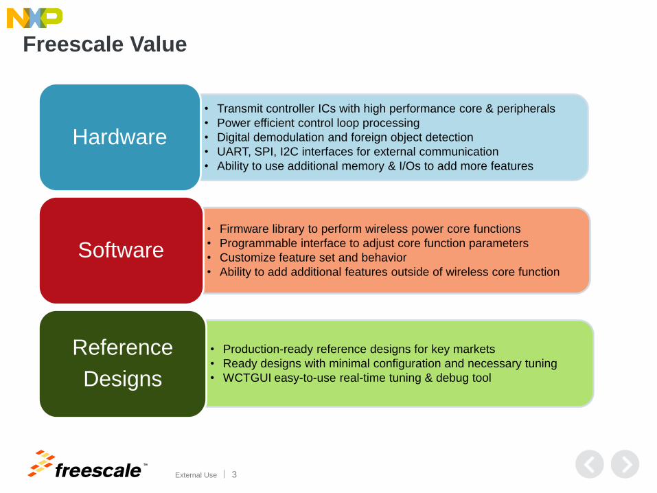
Freescale Value
• Transmit controller ICs with high performance core & peripherals
• Power efficient control loop processing
• Digital demodulation and foreign object detection
• UART, SPI, I2C interfaces for external communication
• Ability to use additional memory & I/Os to add more features
Hardware
• Firmware library to perform wireless power core functions
• Programmable interface to adjust core function parameters
• Customize feature set and behavior
• Ability to add additional features outside of wireless core function
Software
• Production-ready reference designs for key markets
• Ready designs with minimal configuration and necessary tuning
• WCTGUI easy-to-use real-time tuning & debug tool
Reference
Designs

TM
External Use 4
Hardware

TM
External Use 5
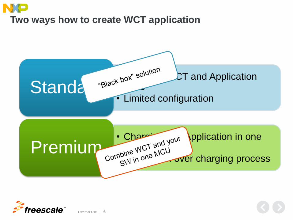
Two ways how to create WCT application
• Separate WCT and Application MCU
• Limited configuration Standard
• Charging and Application in one MCU
• Full control over charging process Premium
TM
External Use 6
Two ways how to create WCT application
• Separate WCT and Application MCU
• Limited configuration Standard
• Charging and Application in one MCU
• Full control over charging process Premium

TM
External Use 9
Software
TM
External Use 10
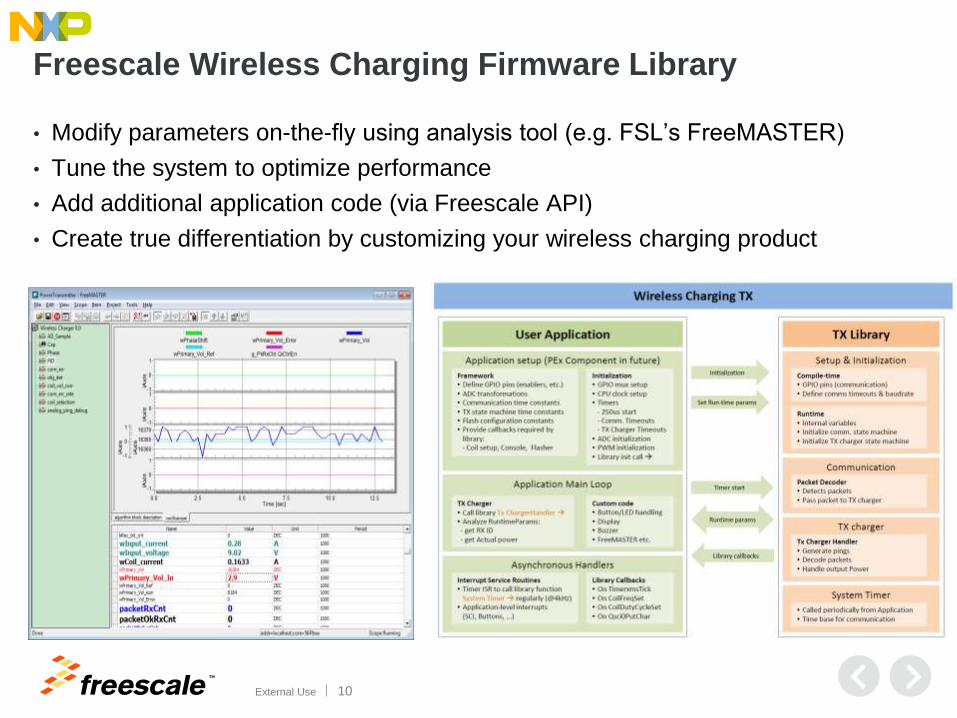
Freescale Wireless Charging Firmware Library
• Modify parameters on-the-fly using analysis tool (e.g. FSL’s FreeMASTER)
• Tune the system to optimize performance
• Add additional application code (via Freescale API)
• Create true differentiation by customizing your wireless charging product

TM
External Use 11
Freescale Wireless Charging Firmware Library
• Pre-defined, encapsulated modules to perform charging core functions
• Configurable hardware layer to limit locked hardware resources
• Add additional application code
• Create true differentiation by customizing your wireless charging product
Freescale API
AD
C
Flash
Tim
er
PIT
IIC
GP
IO
PW
M
JTAG
UA
RT
WCT1xxx Silicon Level Library
Co
il Selectio
n
PID
Co
ntro
l
Rail V
oltag
e Co
ntro
l
Tou
ch S
enso
r
LE
D &
Bu
zzer
QiC
om
mu
nicatio
n
FO
D
Application Level
User Layer• Parameter Calibration & Configuration• Customer Code
A P I
Power ControlFreeMASTER
API
Monitor &
Protection&
Diagnostic
Object
Detection
Processor Layer
Middle Layer
APP Layer
User Layer
Low Power
Mode
FreeMASTER
LIB
Open
Open
TM
External Use 12
Demos
TM
External Use 13
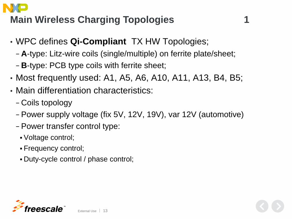
Main Wireless Charging Topologies 1
• WPC defines Qi-Compliant TX HW Topologies;
− A-type: Litz-wire coils (single/multiple) on ferrite plate/sheet;
− B-type: PCB type coils with ferrite sheet;
• Most frequently used: A1, A5, A6, A10, A11, A13, B4, B5;
• Main differentiation characteristics:
− Coils topology
− Power supply voltage (fix 5V, 12V, 19V), var 12V (automotive)
− Power transfer control type:
Voltage control;
Frequency control;
Duty-cycle control / phase control;
TM
External Use 14
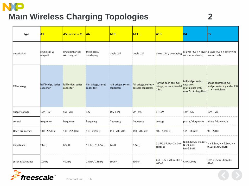
Main Wireless Charging Topologies 2
type A1 A5 (similar to A1) A6 A10 A11 A13 B4 B5
descritpion single coil w magnet
single bifilar coil with magnet
three coils / overlaping
single coil single coil three coils / overlaping n-layer PCB + n-layer wire wound coils;
n-layer PCB + n-layer wire wound coils;
TX topology half bridge, series capacitor;
full bridge, series capacitor;
half bridge, series capacitor;
half bridge, series capacitor;
full bridge, series + parallel capacitor;
for the each coil: full bridge, series + parallel C & L;
full bridge, series capacitor, multiplexer with max 2 coils together;
phase controlled full bridge, series + parallel C & L + multiplexer;
Supply voltage 19V +-1V 5V; 5%; 12V 19V +-1% 5V; 5%; 1 - 12V 12V +-5% 12V +-5%
control frequency frequency frequency frequency frequency voltage phase / duty-cycle phase / duty-cycle
Oper. Frequency 110 - 205 kHz; 110 - 205 kHz; 115 - 205kHz; 110 - 205 kHz; 110 - 205 kHz; 105 - 115kHz; 105 - 113kHz; 96+-2kHz;
inductance 24uH; 6.3uH; 11.5uH / 12.5uH; 24uH; 6.3uH; 11.5/12.5uH; + 2 x 1uH series L;
N x 8.8uH, N x 9.1uH, N x 9.5uH; Lm=3.8uH;
N x 8.8uH, N x 9.1uH, N x 9.5uH; Lm=3.8uH;
series capacitance 100nF; 400nF; 147nF / 136nF; 100nF; 400nF; Cs1 + Cs2 = 200nF; Cp = 400nF;
Cm=300nF; Cm1 = 356nF, Cm23 = 82nF;
TM
External Use 15
Reference Design Enablement
• Schematics, Bill-of-Materials, Gerbers
• Transmitter firmware
• Receiver firmware
• Customizable Software for adding features
• Industry know-how to help enable Wireless Power Consortium’s Qi
product certification
• Available to customers under NDA

TM
External Use 16
A11 Transmitter
Key Features:
− Freescale high performance low power (<5W) wireless transmitter compatible with Qi specs
− 5V DC input voltage
− Guided positioning with single primary coil (A11 type coil)
− Single-stage full-bridge inverter with frequency and duty cycle control
− Low standby power with TSI
− Basic FOD function (Foreign Object Detection)
TM
External Use 17
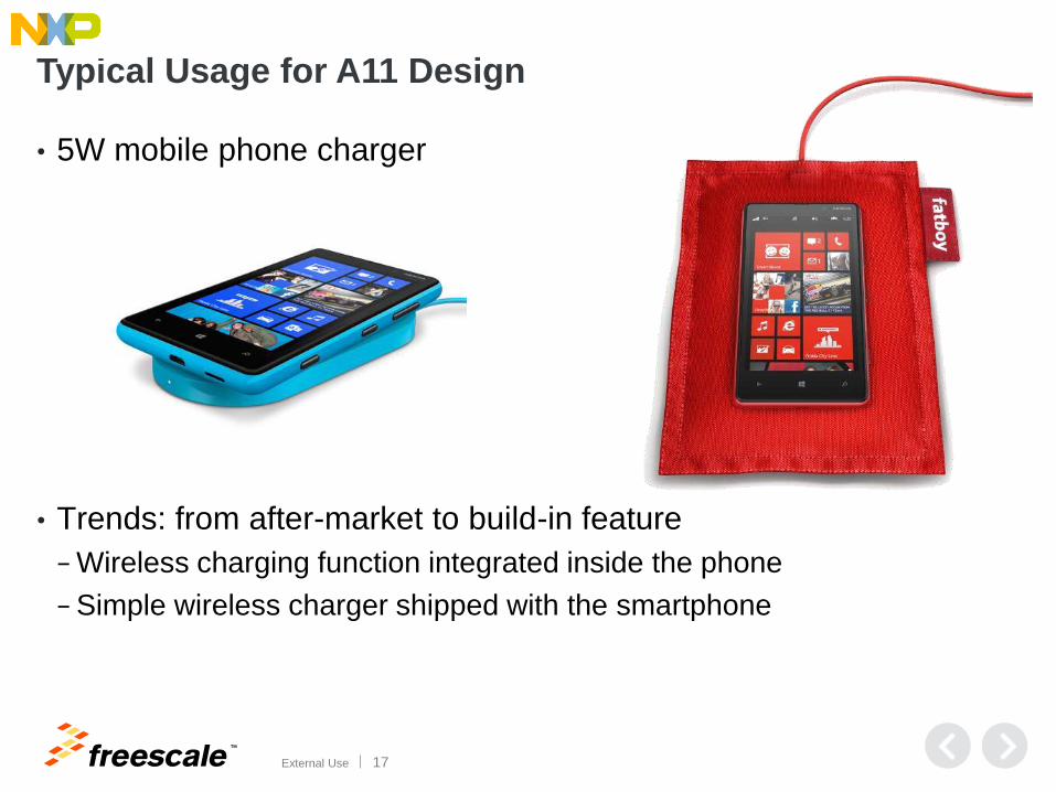
Typical Usage for A11 Design
• 5W mobile phone charger
• Trends: from after-market to build-in feature
− Wireless charging function integrated inside the phone
− Simple wireless charger shipped with the smartphone

TM
External Use 18
Phone Adoption Drives an Accessory Market
Image © Oregon Scientific
Image © Mobee
Image © Nokia
Audio Speakers
with wireless charging Bluetooth headset
with wireless charging
Wireless mouse
with wireless charging
Alarm clock
with wireless charging

TM
External Use 19
Automotive A13 Transmitter
Key Features:
− Freescale automotive low power wireless transmitter compatible with Qi specs
− 6 -16V DC input voltage support
− Free positioning with three primary coils (A13 type coil)
− Two-stage power stage (BUCK + full-bridge) with rail voltage control
− Low standby power with TSI (ver. 2)
− Coil temperature sensing (ver. 2)
− Key FOB avoidance (ver. 2)
− Basic FOD function (ver. 3)
− CAN support (ver. 3)
− NFC co-existence (ver. 3)
− Digital demodulation algorithm (ver. 3)

TM
External Use 20
Typical Usage of A13 Design
• Phone charger in central tunnel
• More position flexibility for charged device
• 5W output
TM
External Use 21
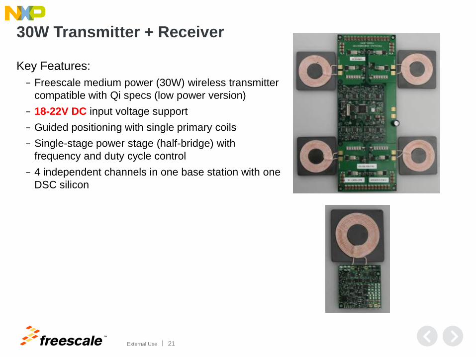
30W Transmitter + Receiver
Key Features:
− Freescale medium power (30W) wireless transmitter
compatible with Qi specs (low power version)
− 18-22V DC input voltage support
− Guided positioning with single primary coils
− Single-stage power stage (half-bridge) with
frequency and duty cycle control
− 4 independent channels in one base station with one
DSC silicon

TM
External Use 22
Typical Usage for 30W Demo
• Industrial battery pack charger
• Tablet charger
TM
External Use 23
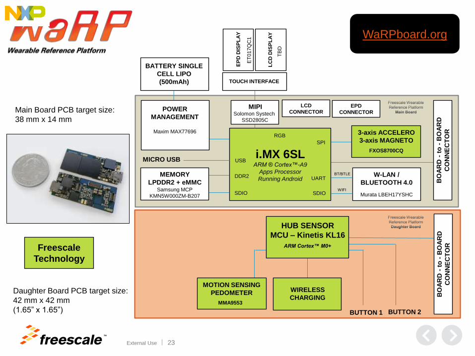
i.MX 6SL ARM ® Cortex™-A9
Apps Processor
Running Android
SPI
3-axis ACCELERO
3-axis MAGNETO
FXOS8700CQ
W-LAN /
BLUETOOTH 4.0
Murata LBEH17YSHC
UART MEMORY
LPDDR2 + eMMC Samsung MCP
KMN5W000ZM-B207
BT/BTLE
SDIO WIFI
DDR2
SDIO
POWER
MANAGEMENT
Maxim MAX77696
BATTERY SINGLE
CELL LIPO
(500mAh)
RGB
BO
AR
D -
to
- B
OA
RD
CO
NN
EC
TO
R
MICRO USB USB
MOTION SENSING
PEDOMETER
MMA9553
WIRELESS
CHARGING
ET
017Q
C1
EP
D D
ISP
LA
Y
LC
D D
ISP
LA
Y
TOUCH INTERFACE
MIPI Solomon Systech
SSD2805C
TB
D
LCD
CONNECTOR EPD
CONNECTOR
BUTTON 1 BUTTON 2
BO
AR
D -
to
- B
OA
RD
CO
NN
EC
TO
R
Main Board PCB target size:
38 mm x 14 mm
Daughter Board PCB target size:
42 mm x 42 mm
(1.65” x 1.65”)
HUB SENSOR
MCU – Kinetis KL16
ARM Cortex™ M0+ Freescale
Technology
WaRPboard.org

TM
External Use 24
Support & Service
TM
External Use 25
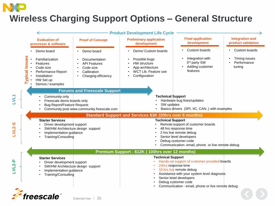
Wireless Charging Support Options – General Structure
• Demo board
• Familiarization
• Features
• Code size
• Performance Report
• Installation
• HW Set up
• Demos / examples
• Demo board
• Documentation
• API Features
• Code size
• Calibration
• Charging efficiency
• Demo/ Custom boards
• Possible bugs
• HW structure
• App architecture
• WCT Lib. Feature use
• Configuration
• Custom boards
• Integration with
3rd party SW
• Adding customer
features
• Custom boards
• Timing issues
• Performance
tuning
Forums and Freescale Support
Starter Services
• Driver development support
• SW/HW Architecture design support
• Implementation guidance
• Training/Consulting
• Community only
• Freescale demo boards only
• Bug Report/Feature Request
• Community post www.community.freescale.com
Evaluation of
processor & software
Product Development Life Cycle
Proof of Concept Preliminary application
development
Final application
development
Integration and
product validation
Typ
ica
l Is
su
es
Standard Support and Services $3K (20hrs over 6 months)
Premium Support - $12K ( 100hrs over 12 months)
Technical Support
• Remote support of customer boards
• 48 hrs response time
• 2 hrs live remote debug
• Senior level developers
• Debug customer code
• Communication- email, phone or live remote debug
Technical Support
• Hands-on support of customer-provided boards
• 24hrs response time
• 10 hrs live remote debug
• Assistance with your system level diagnosis
• Senior level developers
• Debug customer code
• Communication - email, phone or live remote debug
Starter Services
• Driver development support
• SW/HW Architecture design support
• Implementation guidance
• Training/Consulting
LV
L1
LV
L2-S
L
VL
2-P
Technical Support
• Hardware bug fixes/updates
• SW updates
• Basics drivers (SPI, IIC, CAN..) with examples

TM
External Use 26
Solution Support
• Wireless charging firmware − Core modules contained in library are owned by Freescale- NO LIBRARY SOURCE
CODE is provided to customer
− Bug fixes to core modules are provided free of charge
− Bug fixes will become available upon approved release
− Customer is responsible for checking for updates
− Feature enhancements, as defined by Freescale, to the core modules are provided free-of-charge
• Additional functions or capabilities − Some additional features may be demonstrated on certain reference platforms (i.e.
CAN, SPI)
− Non-core functions are provided as demonstrator code-only
− System level changes made, such as magnetic or BOM substitutions are responsibility of customer unless specified by Freescale
− Support for certain applications, such as NFC, are provided by third-party partners where appropriate
− Deviations from the base platform or solution provided by Freescale are the customer’s responsibility, and support cannot be guaranteed
TM
External Use 27
More Information
• For more information about Freescale’s wireless charging solutions,
visit www.freescale.com/wirelesscharging
• For information on Freescale’s 5W single-coil wireless charging
reference design, visit: www.freescale.com/5w1coiltx
• Link to FreeMASTER Installation package (37.4MB), User Manual
is in “Help” of the installed software
• https://cache.freescale.com/secured/microcontrollers/software/app_
software/application_development_framework/FMASTERSW.exe?fi
leExt=.exe&__gda__=1399300568_1b003f47a204269d1e8261f99d
f83409
TM
© 2014 Freescale Semiconductor, Inc. | External Use
www.Freescale.com


