
Fiberglass CrossflowField-Erected Cooling Towers
We do things differently and it makes all the difference for you..™
3000XLF™
ISO 9001:2008Lit.# B 302 A 01 /16
4150 International Plaza, Suite 500Fort Worth, Texas 76109-4826817.246.8700 phone817.246.8717 fax
www.compositecooling.com
Composite Cooling Solutions (CCS) is a custom cooling tower solutions provider specializing in the design and build of field-erected fiberglass and concrete cooling towers. Our exclusive tower structure is unlike any other on the market — using custom-engineered components and a flexible, open-frame design to enable faster and safer project execution and lower costs over the life of the tower. From our founding leaders who pioneered the cooling tower industry to our experienced and responsive teams, you can rely on CCS to deliver a lasting solution for your cooling needs.
We do things differently and it makes all the difference for you.™
Front cover: This single-cell 3000XLF fiberglass crossflow cooling tower serves a community college campus.
Composite Cooling Solutions’ cooling towers (or parts thereof) are covered and protected by one or more of the following United States Patents (and other pending U.S. patent applications): U.S. Patent No. 7,257,734, U.S. Patent No. 7,607,646, U.S. Patent No. 7,997,562, U.S. Patent No. 8,376,323 and U.S. Patent No. 8,602,397
Member
CCS 3000XLF™ Fiberglass CrossflowField-Erected Cooling Towers

At CCS we have designed an exclusive tower structure that is unlike any otheron the market — providing real and lasting advantages for you.
Better material-to-labor cost ratioOur exclusive tower structure and streamlined build process typically equate to a 35% reduction in labor hours, so we can invest more of your budget into the high-quality materials that stay on site and create return value.
Reduced operating costsBecause our towers can be built to the exact footprint available, we are able to utilize the optimal motor size and lowest horsepower possible to increase efficiency and reduce utility bills.
Lower maintenance costsThe open-frame design of our towers allows easy access to the basin, making it faster and less costly to clean and inspect. Exclusive tower features like our patented connections with no annual torque requirements and our thicker, longer-lasting UV coating yield on-going maintenance savings.
Longer tower lifeCCS towers are engineered for a minimum structural design life of 50 years, ensuring that your investment will pay off for years to come before a replacement is needed.
Confidence of working with the FRP expertsFrom our founding leaders who developed the first fiberglass tower in 1981 to the construction of North America’s largest crossflow FRP tower in 2010, CCS has more FRP tower experience than any other provider.
Solutions to your unique challengesWhen you work with CCS, you benefit from the extensive knowledge and ingenuity of our people across all functions — from our engineers and sales team to our project managers and local representatives. As a custom tower provider, we work with each customer individually to design the best solution to fit the requirements.
Effective and efficient serviceCCS provides responsive service and follow-up on initial inquiries and submittals, during project execution and for any post-installation issues. We have a solid reputation in the industry for delivering on our promises and producing quality results.
Accountable partner you can trustMore than just a vendor, we are a partner who stands behind the quality of our products and forms lasting relationships with our customers. In fact, 80% of them come back to buy from CCS again.
Superior Quality and Reliability Optimal Project Execution Lower Lifecycle Costs Affirming Customer Experience
Up to 200% greater rigidity in our raw materialWe custom manufacture our FRP material using a special glass lay-up and higher glass content with no fillers in our resin for increased tensile strength and shear resistance.
Greater UV protection and wider pH range for chemical resistanceOur resin coating is 2-4x thicker than our competitors’ standard resin, making our towers better able to withstand the elements, including extreme temperatures and sun damage.
More durable structure made with custom componentsCCS does not rely on “off-the-shelf” shapes. Our components are designed, engineered and tested specifically for cooling tower use.
Stronger connections and tighter jointsOur patented two- and three-bolt structural connections are stable without spacers or torquing, and we anchor every column to the basin.
More flexibility in performanceOur Multi-Flo™ distribution system allows the number, location and capacity of spray nozzles to be optimized to match tower dimensions and performance requirements. With Multi-Flo, turndown capabilities can be as low as 30-50% of total capacity for efficient tower operation through a wider range of load conditions.
ThermaFit™ for optimal designCCS’ ThermaFit software is a powerful sizing and selection tool that helps engineers and CCS representatives design and select the optimal tower design for the application from a range of possibilities. This saves valuable design time up front, matching size and performance requirements without being restricted by other manufacturers’ “standard product” limitations.
Shorter lead timeWe developed a proprietary software system to automate structural design and bill of materials, enabling industry-leading delivery time of materials to site.
Flexibility to fit any footprintOnly CCS uses 6 x 6-inch “power columns” that can be spaced at any increment up to 15 feet apart. That means our towers can be matched to the exact space available for improved efficiency and lower energy costs. 25-35% faster installation for less time on siteWith larger columns and spacing, our structure requires 75-85% fewer columns, connections and hardware pieces than other providers’ towers — significantly reducing the training and installation hours needed. Our lean assembly processes include pre-packaged/marked components and standardized hardware to eliminate guesswork and lower risk by reducing overall time on site.
Safer construction with fewer potential interruptionsOur stable, open-frame design allows the crew to tie-off anywhere on the structure and provides room in the basin to maneuver scissor lifts rather than working from ladders and scaffolding, increasing safety and efficiency.
CCS 3000XLF fiberglass crossflow field-erected cooling towers serve mission-critical facilities, such as universities, hospitals and data centers. This two-cell CCS 3000XLF supports a data center for one of the nation’s preeminent insurance companies.
Tons Per Cell 300 1000 2000 3000 4000
Counterflow
CCS Cooling Tower Capacities The CCS 3000XLF fiberglass crossflow field-erected cooling tower is the ideal choice for projects when 1,000 - 3,000 tons per cell is required.
Crossflow
Phoenix®PermaLite™
Titan™3000XLF™
Materials
CC
S
Co
mp
etit
or
55%
45%
75%
25%
Labor
1. Butterfly Control Valves • More positive balancing of distribution • True flow control valve superior to
dump valve
2. Motor • 50 HP to 150 HP • Located outside airstream • Inverter duty compatible
3. Hot Water Basin Cover • Removable • Same elevation as fan deck, eliminating
trip hazard
4. FRP Fan Stack • Includes view port and access door
5. FRP Manual Adjusted Pitch Fan • Moment balanced at factory • Corrosion resistant
6. Gear Drive • Right-angle gear • Epoxy coated • Vibration and oil level cut-off
switches pre-mounted
7. HDG Steel Support/Distribution Header
8. Patented Hot Water Distribution System • Uniform distribution of hot water
over nozzles • FRP cover in easy-to-remove sections • Low pump head, gravity flow
Distribution basin • Large orifice target nozzles
9. Distribution Header Inlet • Single-inlet distribution system • One inlet per cell
10. FRP Handrails • OSHA compliant
11. FRP Casing • 12 oz. or greater fire retardant casing • UV resistant • Corrosion resistant
12. FRP Access Door
13. Open Plenum Area • Fewer structural obstructions • Facilitates maintenance
14. Column Anchors • Every column anchored to basin • Stainless steel • 316 stainless steel (optional)
15. FRP Fill Pack Supports
16. PVC Fill Pack • Bottom-supported, facilitating installation and
maintenance • Superior to hanging fill systems • Integrated drift eliminators (standard) • Elevated above the cold water basin for easy
maintenance
17. FRP Blade Louvers (Optional)
2
3
1 54 87 10
6 9
11 12 13
14
15 16 17
For building trades and light industrial applications where extended equipment life is required, the 3000XLF fiberglass crossflow field-erected cooling tower provides superior structure, the ultimate in corrosion protection and optimal performance.
Optimized Design• All-fiberglass structure can be designed for specific
seismic and wind conditions per the International Building Code or ASCE-7
• Engineered to minimize structural air restriction • Motor located outside saturated airstream• Positive shut-off butterfly valves for optimal
flow control• Superior crossflow fill media• Bottom-supported crossflow fill• Patented hot water distribution system• Increased safety with FRP distribution cover
at same elevation as fan deck• Designed to outlive the facility it serves
Non-Corrosive Construction Components• Fiberglass structural components • Rigid fiberglass fan deck and fan stacks• FRP blade louvers standard• Fiberglass hot water basin and basin cover• Type 304 stainless steel hardware• 100% locknuts on all structure hardware
Performance Benefits• Aesthetically pleasing design• Energy efficient• Quiet operation• Reliable year-round performance• Extended service life• Environmentally friendly
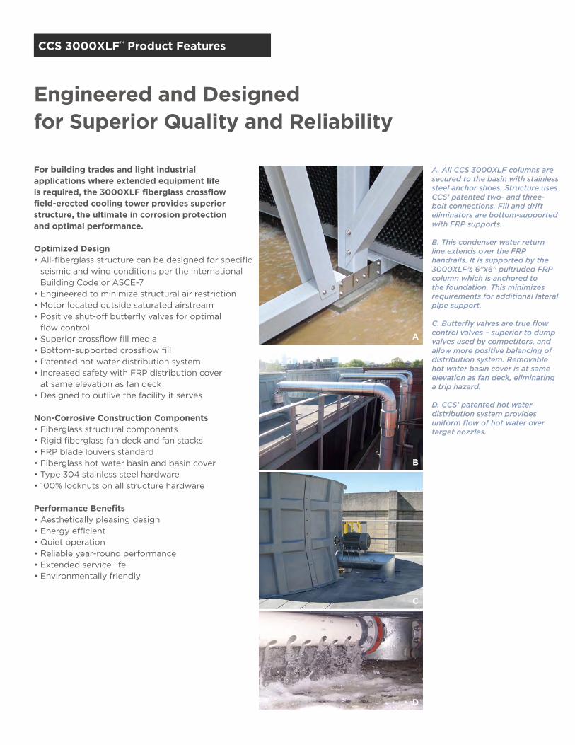
A. All CCS 3000XLF columns are secured to the basin with stainless steel anchor shoes. Structure uses CCS’ patented two- and three-bolt connections. Fill and drift eliminators are bottom-supported with FRP supports.
B. This condenser water return line extends over the FRP handrails. It is supported by the 3000XLF’s 6”x6” pultruded FRP column which is anchored to the foundation. This minimizes requirements for additional lateral pipe support.
C. Butterfly valves are true flow control valves – superior to dump valves used by competitors, and allow more positive balancing of distribution system. Removable hot water basin cover is at same elevation as fan deck, eliminating a trip hazard.
D. CCS’ patented hot water distribution system provides uniform flow of hot water over target nozzles.
CCS 3000XLF™ Product Features CCS 3000XLF™ Product Features
Engineered and Designed for Superior Quality and Reliability
A
B
C
D

1. Butterfly Control Valves • More positive balancing of distribution • True flow control valve superior to
dump valve
2. Motor • 50 HP to 150 HP • Located outside airstream • Inverter duty compatible
3. Hot Water Basin Cover • Removable • Same elevation as fan deck, eliminating
trip hazard
4. FRP Fan Stack • Includes view port and access door
5. FRP Manual Adjusted Pitch Fan • Moment balanced at factory • Corrosion resistant
6. Gear Drive • Right-angle gear • Epoxy coated • Vibration and oil level cut-off
switches pre-mounted
7. HDG Steel Support/Distribution Header
8. Patented Hot Water Distribution System • Uniform distribution of hot water
over nozzles • FRP cover in easy-to-remove sections • Low pump head, gravity flow
Distribution basin • Large orifice target nozzles
9. Distribution Header Inlet • Single-inlet distribution system • One inlet per cell
10. FRP Handrails • OSHA compliant
11. FRP Casing • 12 oz. or greater fire retardant casing • UV resistant • Corrosion resistant
12. FRP Access Door
13. Open Plenum Area • Fewer structural obstructions • Facilitates maintenance
14. Column Anchors • Every column anchored to basin • Stainless steel • 316 stainless steel (optional)
15. FRP Fill Pack Supports
16. PVC Fill Pack • Bottom-supported, facilitating installation and
maintenance • Superior to hanging fill systems • Integrated drift eliminators (standard) • Elevated above the cold water basin for easy
maintenance
17. FRP Blade Louvers (Optional)
2
3
1 54 87 10
6 9
11 12 13
14
15 16 17
For building trades and light industrial applications where extended equipment life is required, the 3000XLF fiberglass crossflow field-erected cooling tower provides superior structure, the ultimate in corrosion protection and optimal performance.
Optimized Design• All-fiberglass structure can be designed for specific
seismic and wind conditions per the International Building Code or ASCE-7
• Engineered to minimize structural air restriction • Motor located outside saturated airstream• Positive shut-off butterfly valves for optimal
flow control• Superior crossflow fill media• Bottom-supported crossflow fill• Patented hot water distribution system• Increased safety with FRP distribution cover
at same elevation as fan deck• Designed to outlive the facility it serves
Non-Corrosive Construction Components• Fiberglass structural components • Rigid fiberglass fan deck and fan stacks• FRP blade louvers standard• Fiberglass hot water basin and basin cover• Type 304 stainless steel hardware• 100% locknuts on all structure hardware
Performance Benefits• Aesthetically pleasing design• Energy efficient• Quiet operation• Reliable year-round performance• Extended service life• Environmentally friendly
A. All CCS 3000XLF columns are secured to the basin with stainless steel anchor shoes. Structure uses CCS’ patented two- and three-bolt connections. Fill and drift eliminators are bottom-supported with FRP supports.
B. This condenser water return line extends over the FRP handrails. It is supported by the 3000XLF’s 6”x6” pultruded FRP column which is anchored to the foundation. This minimizes requirements for additional lateral pipe support.
C. Butterfly valves are true flow control valves – superior to dump valves used by competitors, and allow more positive balancing of distribution system. Removable hot water basin cover is at same elevation as fan deck, eliminating a trip hazard.
D. CCS’ patented hot water distribution system provides uniform flow of hot water over target nozzles.
CCS 3000XLF™ Product Features CCS 3000XLF™ Product Features
Engineered and Designed for Superior Quality and Reliability
A
B
C
D

CCS 3000XLF™ Engineering Data CCS 3000XLF™ Engineering Data
CL CLCL
CL
C L
CL
This information is intended for guidelines and preliminary information only. Do not use for construction.
Purchaser to design and furnish concrete basin, sumps, drains, overflows, water makeup, etc.
Sleeved anchor bolts are to be 3/4" diameter with 2" projection. Each bolt to have 1 1/2" minimum usable thread, one washer, and one nut.
Design basin depth is 1'–4". Deeper basins require piers provided by Others.
Adequate clearance for construction and air supply must be maintained around the tower. Consult your CCS representative for assistance.
Catalog Model No. Nominal Tons1
MotorHP
Weights2 Dimensions3
No. of
BaysL W H4 A B C D EShipping Operating
XLF1222-60 930 6013,214 22,104 12’ 22’ 25’–5” 12’–6” 4’–9” N/A 24’ 9” 1
XLF1222-75 1000 75
XLF1424-50 1023 50
16,397 26,768 14’ 24’ 25’–5” 14’–6” 4’–9” N/A 26’ 9” 1XLF1424-60 1075 60
XLF1424-75 1150 75
XLF1424-100 1250 100
XLF1629-75 1345 7523,306 39,664 16’ 29’ 23’–11” 15’–6” 6’–9” 8’–0” 31’ 9” 2
XLF1629-100 1465 100
XLF1830-75 1474 7526,849 45,252 18’ 30’ 23’–11” 16’–6” 6’–9” 9’–0” 32’ 9” 2
XLF1830-100 1605 100
XLF2031-75 1597 7530,532 50,980 20’ 31’ 23’–11” 17’–6” 6’–9” 10’–0” 33’ 9” 2
XLF2031-100 1739 100
XLF2433-75 1834 75
38,318 62,856 24’ 33’ 23’–11” 19’–6” 6’–9” 12’–0” 35’ 9” 2XLF2433-100 1998 100
XLF2433-125 2134 125
XLF2834-100 2234 100
45,685 74,312 28’ 34’ 23’–11” 20’–6” 6’–9” 14’–0” 36’ 9” 2XLF2834-125 2387 125
XLF2834-150 2519 150
XLF3238-100 2473 100
56,691 89,408 32’ 38’ 23’–11” 24’–6” 6’–9” 10’–8” 40’ 9” 3XLF3238-125 2643 125
XLF3238-150 2800 150
1. Based on 3 GPM per ton at 95°F-85°F-78°F, ASL.2. Weights and loads are in pounds. Weights are for cooling tower only, on concrete basin (supplied by Others).3. All dimensions are nominal.4. From top of basin curb to top of fan stack.
Single Hot Water InletPer Cell
Len
gth
(at
o
f co
lum
n B
ase)
(L
)
Width (at column Base) (W)
Width (W) Length (L)
Hei
gh
t (H
)4
Top View
Side Views
Typical Sump/Cell (Hydraulic Design by Others)
Concrete Basin (by Others)
Cel
l Wid
th (
W)
Bas
in W
idth
(D
)
(B)
(B)
(C)(E) (E)
(A)
Cas
ed E
nd
Wal
l
Cas
ed E
nd
Wal
l
Cell Length (L)
Columns
Co
lum
ns
Columns
Air Inlet Air Inlet
CL
CL
CLCL
C L
C LC L
C L
Air Inlet Air Inlet
Tower Length = Number of Cells × (L)
Basin Length = Number of Cells × (L) + (2 × [E])
Multi-Cells
3000XLF on Concrete Basin
Minimum Operating Water Level
Minimum Operating Water Level
Basin Depth
Top of Basin Curb8"1' - 4"

This information is intended for guidelines and preliminary information only. Do not use for construction.
Purchaser to design, furnish, and install grillage.
Supporting members must be level and flush at top. Maximum beam deflection is 1/240 span or 1/2”, whichever is less.
For recommendations for sump design, size, and location, consult your CCS representative.
Adequate clearance for construction and air supply must be maintained around the tower. Consult your CCS representative for assistance.
Catalog Model No. Nominal Tons1
MotorHP
Weights2 Dimensions5
No. of
BaysL W H6 A B CD
EShipping Normal Operating3
Maximum Overflow4
FRP SS
XLF1222-60 930 6015,732 38,818 65,985 12’ 22’ 25’–4” 12’–6” 4’–9” N/A 26’ 24’ 9” 1
XLF1222-75 1000 75
XLF1424-50 1023 50
19,443 47,454 83,980 14’ 24’ 25’–4” 14’–6” 4’–9” N/A 28’ 26’ 9” 1XLF1424-60 1075 60
XLF1424-75 1150 75
XLF1424-100 1250 100
XLF1629-75 1345 7527,261 67,182 108,240 16’ 29’ 23’–10” 15’–6” 6’–9” 8’–0” 33’ 31’ 9” 2
XLF1629-100 1465 100
XLF1830-75 1474 7531,335 76,870 125,970 18’ 30’ 23’–10” 16’–6” 6’–9” 9’–0” 34’ 32’ 9” 2
XLF1830-100 1605 100
XLF2031-75 1597 7535,571 86,889 144,635 20’ 31’ 23’–10” 17’–6” 6’–9” 10’–0” 35’ 33’ 9” 2
XLF2031-100 1739 100
XLF2433-75 1834 75
44,531 107,919 184,760 24’ 33’ 23’–10” 19’–6” 6’–9” 12’–0” 37’ 35’ 9” 2XLF2433-100 1998 100
XLF2433-125 2134 125
XLF2834-100 2234 100
52,982 127,893 222,085 28’ 34’ 23’–10” 20’–6” 6’–9” 14’–0” 38’ 36’ 9” 2XLF2834-125 2387 125
XLF2834-150 2519 150
XLF3238-100 2473 100
65,729 156,657 283,670 32’ 38’ 23’–10” 24’–6” 6’–9” 10’–8” 42’ 40’ 9” 3XLF3238-125 2643 125
XLF3238-150 2800 150
1. Based on 3 GPM per ton at 95°F-85°F-78°F, ASL.2. Operating and maximum overflow weights include tower, basin, and water. Weights and loads are in pounds. 3. Basin weight when water reaches normal operating level.4. Basin weight when water reaches maximum overflow level. 5. All dimensions are nominal.6. From top of basin curb to top of fan stack.
CCS 3000XLF™ Engineering Data CCS 3000XLF™ Engineering Data
Basin Support Steel Grillage (by Others)
1 Sump per Cell 1 Sump per Cell
Cel
l Wid
th (
W)
Bas
in W
idth
(D
)
(B)
(B)
(C)(E) (E)
(A)
Cas
ed E
nd
Wal
l
Cas
ed E
nd
Wal
l
Cell Length (L)
Columns
Co
lum
ns
Columns
Air Inlet
Air Inlet Air Inlet
Air Inlet
Length = Number of Cells × (L)
Multi-Cells
Steel Grillage (by Others)
CLCL
C LC L
Minimum Operating Water Level
Minimum Operating Water Level
Basin Depth
Top of Basin Curb8"
1' - 4"
CL CLCL
CL
C L
CL
Single Hot Water InletPer Cell
Len
gth
(at
o
f co
lum
n B
ase)
(L
)
Width (at column Base) (W)
Width (W) Length (L)
Hei
gh
t (H
)6
Top View
Side Views
3000XLF on FRP or Stainless Steel Basin

The CCS 3000XLF Fiberglass Crossflow Field-Erected Cooling Tower is typically an ideal choice for the building trades and industrial market segments when requiring 1,000 - 3,000 tons per cell. Consider the following parameters when planning your project:
Clockwise from top left:
Data Center - Tampa, FLMedical Center - Indianapolis, INOffice Building - Fort Worth, TXProcess Facility - Tampa, FLCollege Campus - San Angelo, TXUniversity Campus - Tulsa, OK
CCS 3000XLF™ Market Segments CCS 3000XLF™ Design Criteria
The CCS 3000XLF Fiberglass Crossflow Field-Erected Cooling Tower supports commercial, industrial and process mission-critical facilities when superior quality and reliability count.
Project Name
City
Engineering Firm
Name
Phone
Budget Workup Needed
Projected RFP Bid
Pre-bid Meeting
Projected Start
Projected Completion
Site Photographs Available
Project Drawings Available
Project Specifications Available
Load Drawing Required
Proposal Drawings Required
Proposal Specifications Required
EnginEEring ConTraCT
YES no
TimE rEquirEmEnTS
Project
Special Design Considerations
ft dBa ppm suspended solids in circulating water ft from tower
HEigHT LimiTaTion From gradE Sound WaTEr quaLiTY
No. of Towers No. of Cells
Commercial
Industrial
Fiberglass
Crossflow
appLiCaTion
ToWEr maTEriaL
dESign CondiTionS
ToWEr TYpE CELL arrangEmEnT air inLET TYpE
Project Design Criteria
Number of stories Height above roof ft
aCCESS
Number of Ladder(s) Number of Staircase(s)
°F
°F
°F
ToWEr LoCaTion
Length ft x Width ft = ft2
maXimum ToWEr arEa SpaCE providEd
Basin Depth in From basin floor to top of curb
Elevation ft EL AMSL
Length ft x Width ft = ft2
maXimum BaSin arEa
In-Line
Individual
On grade
Double
BaSin maTEriaL
Concrete
Fiberglass
Stainless Steel
oWnEr prioriTY
Max GPM
Min CWT
Max WBT
RooftopTotal GPM
HWT
CWT
WBT

Fiberglass CrossflowField-Erected Cooling Towers
We do things differently and it makes all the difference for you..™
3000XLF™
ISO 9001:2008Lit.# B 302 A 01 /16
4150 International Plaza, Suite 500Fort Worth, Texas 76109-4826817.246.8700 phone817.246.8717 fax
www.compositecooling.com
Composite Cooling Solutions (CCS) is a custom cooling tower solutions provider specializing in the design and build of field-erected fiberglass and concrete cooling towers. Our exclusive tower structure is unlike any other on the market — using custom-engineered components and a flexible, open-frame design to enable faster and safer project execution and lower costs over the life of the tower. From our founding leaders who pioneered the cooling tower industry to our experienced and responsive teams, you can rely on CCS to deliver a lasting solution for your cooling needs.
We do things differently and it makes all the difference for you.™
Front cover: This single-cell 3000XLF fiberglass crossflow cooling tower serves a community college campus.
Composite Cooling Solutions’ cooling towers (or parts thereof) are covered and protected by one or more of the following United States Patents (and other pending U.S. patent applications): U.S. Patent No. 7,257,734, U.S. Patent No. 7,607,646, U.S. Patent No. 7,997,562, U.S. Patent No. 8,376,323 and U.S. Patent No. 8,602,397
Member
CCS 3000XLF™ Fiberglass CrossflowField-Erected Cooling Towers


