
Utility-based Bandwidth Adaptation for QoS Provisioning in Multimedia
Wireless Networks
Ning Lu
Submitted for the degree of Doctor of Philosophy
Department of Electronic Engineering
Queen Mary, University of London
United Kingdom
April 2007

To my parents

i
Abstract
In the past few years the wireless communications community has witnessed a
tremendous growth in multimedia traffic. Providing Quality of Service (QoS) to
various multimedia services according to their bandwidth requirements is an
important resource management issue for wireless networks. However, due to the
limited and variable wireless link bandwidth the resource management in wireless
networks is a challenging problem.
Bandwidth adaptation is one of the most promising resource management
methods to support multimedia traffic in wireless networks. With bandwidth
adaptation, the allocated bandwidth of ongoing calls can be adjusted dynamically to
cope with the resource fluctuations in wireless networks. This thesis investigates
how to apply bandwidth adaptation techniques to provide QoS guarantees in
multimedia wireless networks.
The bandwidth adaptation schemes described in this thesis are based on
application utility functions that reflect the satisfaction degree of end-users with the
allocated bandwidth. First, multimedia traffic is categorized into different classes
according to their adaptive characteristics and a utility function with an appropriate
shape is formulated for each class of traffic. With the availability of application
utility functions, the utility-based adaptive traffic model is presented for multimedia
traffic. Following that, several utility-based QoS requirements are analyzed from
the perspectives of both network operators and end-users, and a series of bandwidth
adaptation schemes are proposed to meet these QoS objectives.
A multimedia wireless network simulation model has been developed to
evaluate the proposed bandwidth adaptation schemes. In the simulation
experiments, apart from the traditional performance metrics of wireless networks,
e.g. call blocking probability and handoff dropping probability, several new utility-
based performance metrics are also introduced. Simulation results have clearly
demonstrated the superior performance of the proposed bandwidth adaptation
schemes by comparing them with some existing ones.

ii
Acknowledgements
First of all, I would like to express my sincere gratitude to my supervisor Dr.
John Bigham for his invaluable guidance, persistent encouragement, great patience
and kindness during my PhD study at the Department of Electronic Engineering,
Queen Mary, University of London. John gives me complete freedom to define the
research topic according to my interest and provides me the assistance whenever I
need. Working with him is proven to be an enjoyable and rewarding experience.
Next, I would like to thank Prof. Laurie Cuthbert, Dr. Eliane Bodanese, Dr. Yue
Chen and Dr. Athen Ma for their helpful suggestions and comments on my
research.
Thanks also go to the administrative and technical staff in the department. In
particular I want to thank Kok Ho Huen, Lynda Rolfe and Melissa Yeo for their
tremendous help and support.
I am grateful to many other wonderful colleagues and friends at Queen Mary.
They have made my time in the past few years really pleasurable and memorable.
I also want to acknowledge the US Office of Navy Research who has provided
some of the financial support for my work.
Finally, my gratitude goes to my parents for their great love and endless support.

iii
Table of Contents
Abstract........................................................................................................ i
Acknowledgements.................................................................................... ii
Table of Contents ...................................................................................... iii
List of Figures............................................................................................vi
List of Tables ............................................................................................. ix
Abbreviations..............................................................................................x
Chapter 1 Introduction ...........................................................................1
1.1 Motivation .............................................................................................. 1
1.2 Contribution............................................................................................ 2
1.3 Organization of the Thesis...................................................................... 3
Chapter 2 Background ...........................................................................5
2.1 Introduction ............................................................................................ 5
2.2 Evolution of Wireless Networks............................................................. 5
2.2.1 The First Generation (1G) Wireless Networks........................... 6
2.2.2 The Second Generation (2G) Wireless Networks ...................... 6
2.2.3 The Third Generation (3G) Wireless Networks ......................... 8
2.2.4 The Fourth Generation (4G) Wireless Networks ..................... 10
2.3 Organization of Wireless Networks ..................................................... 12
2.4 Resource Management in Wireless Networks...................................... 13
2.4.1 CAC.......................................................................................... 14
2.4.2 Bandwidth Allocation............................................................... 14
2.4.3 Bandwidth Reservation............................................................. 15
2.5 QoS in Multimedia Wireless Networks................................................ 16
2.5.1 Challenges of QoS Provisioning............................................... 16
2.5.2 Measurements of QoS .............................................................. 17
2.5.3 Previous Work on QoS Provisioning........................................ 18

iv
2.6 Summary............................................................................................... 20
Chapter 3 Utility-based Bandwidth Adaptation Foundation .............21
3.1 Introduction .......................................................................................... 21
3.2 Utility-based Multimedia Traffic Model .............................................. 21
3.2.1 Utility Functions ....................................................................... 21
3.2.2 Utility Functions Formulation for Multimedia Traffic............. 22
3.2.3 The Quantization of Utility Functions...................................... 27
3.3 Multimedia Adaptation Implementation in Wireless Networks........... 29
3.3.1 Multimedia Adaptation Architecture........................................ 29
3.3.2 Multimedia Adaptation Techniques ......................................... 30
3.4 Utility-based Bandwidth Adaptation Objectives.................................. 32
3.5 Utility-based Bandwidth Adaptation Procedure................................... 33
3.5.1 Bandwidth Degrades................................................................. 34
3.5.2 Bandwidth Upgrades ................................................................ 35
3.6 Summary............................................................................................... 36
Chapter 4 Utility-Maximization Bandwidth Adaptation .....................37
4.1 Introduction .......................................................................................... 37
4.2 Related Work........................................................................................ 38
4.3 Problem Formulation............................................................................ 39
4.3.1 Bandwidth Degrades................................................................. 39
4.3.2 Bandwidth Upgrades ................................................................ 41
4.4 The Proposed Utility-Maximization Algorithm ................................... 42
4.5 CAC and Bandwidth Reservation......................................................... 47
4.6 Simulation Modelling ........................................................................... 50
4.6.1 Network Model......................................................................... 50
4.6.2 Traffic Model............................................................................ 51
4.6.3 Simulator .................................................................................. 53
4.7 Simulation Verification and Validation................................................ 56
4.7.1 Verification............................................................................... 56
4.7.2 Validation ................................................................................. 56
4.8 Numerical Results................................................................................. 61
4.9 Summary............................................................................................... 69
v
Chapter 5 Utility-Fair Bandwidth Adaptation .....................................70
5.1 Introduction .......................................................................................... 70
5.2 Related Work........................................................................................ 70
5.3 The Definition of Utility Fairness ........................................................ 72
5.4 Problem Formulation............................................................................ 74
5.4.1 Bandwidth Degrades................................................................. 74
5.4.2 Bandwidth Upgrades ................................................................ 74
5.5 The Proposed Utility-Fair Algorithm ................................................... 75
5.6 CAC and Bandwidth Reservation......................................................... 77
5.7 Simulation Results................................................................................ 80
5.8 Summary............................................................................................... 85
Chapter 6 Utility-based Multi-Objective Bandwidth Adaptation .......86
6.1 Introduction .......................................................................................... 86
6.2 Problem Formulation............................................................................ 87
6.2.1 Bandwidth Degrades................................................................. 87
6.2.2 Bandwidth Upgrades ................................................................ 88
6.3 The Proposed Utility-based Multi-Objective Algorithm...................... 89
6.4 CAC and Bandwidth Reservation......................................................... 99
6.5 Simulation Results.............................................................................. 100
6.6 Summary............................................................................................. 107
Chapter 7 Conclusions and Future Work .........................................108
7.1 Conclusions ........................................................................................ 108
7.2 Future Work........................................................................................ 109
Appendix A Author’s Publications.......................................................112
References ..............................................................................................114

vi
List of Figures
Figure 2.1 Evolution of wireless networks................................................................ 5
Figure 2.2 The vision of 4G networks..................................................................... 11
Figure 2.3 The organization of wireless networks .................................................. 12
Figure 2.4 The initiation of new and handoff calls ................................................. 13
Figure 3.1 The utility function of adaptive real-time traffic ................................... 23
Figure 3.2 The utility function of hard real-time traffic .......................................... 26
Figure 3.3 The utility function of non-real-time traffic........................................... 27
Figure 3.4 Utility functions quantization using equal utility interval ..................... 29
Figure 3.5 Utility functions quantization using equal bandwidth interval .............. 29
Figure 3.6 Multimedia adaptation at different OSI layers [SEM03]....................... 30
Figure 3.7 Example of layer encoded multimedia................................................... 31
Figure 3.8 Bandwidth adaptation trigger events...................................................... 34
Figure 3.9 Bandwidth degrades procedure.............................................................. 35
Figure 3.10 Bandwidth upgrades procedure............................................................ 36
Figure 4.1 The degradable utility function of the -thi ongoing call ....................... 40
Figure 4.2 The upgradable utility function of the -thi ongoing call....................... 41
Figure 4.3 Bandwidth allocation tree ...................................................................... 43
Figure 4.4 The layout of the wireless network model ............................................. 51
Figure 4.5 Call blocking probability for traffic group 0.......................................... 59

vii
Figure 4.6 Call blocking probability for traffic group 1.......................................... 59
Figure 4.7 Call blocking probability for traffic group 2.......................................... 60
Figure 4.8 Call blocking probability for traffic group 3.......................................... 60
Figure 4.9 Call blocking probability for traffic group 4.......................................... 61
Figure 4.10 Call blocking probability for traffic group 5........................................ 61
Figure 4.11 The parameters of the call in RBBS [ELK02] ..................................... 62
Figure 4.12 Average cell utility............................................................................... 64
Figure 4.13 Call blocking probability for combined traffic .................................... 65
Figure 4.14 Handoff dropping probability for combined traffic ............................. 66
Figure 4.15 Handoff dropping probability for traffic Class I .................................. 67
Figure 4.16 Handoff dropping probability for traffic Class II................................. 67
Figure 4.17 Average call degradation ratio ............................................................. 68
Figure 4.18 Bandwidth utilization........................................................................... 69
Figure 5.1 An example wireline network with multiple links and flows [BER92]. 72
Figure 5.2 Finding the utility-fair bandwidth allocation for two utility functions .. 77
Figure 5.3 Utility fairness deviation........................................................................ 82
Figure 5.4 Average cell utility................................................................................. 82
Figure 5.5 Call blocking probability for combined traffic ...................................... 83
Figure 5.6 Handoff dropping probability for combined traffic ............................... 83
Figure 5.7 Average call degradation ratio ............................................................... 84
Figure 5.8 Bandwidth utilization............................................................................. 85

viii
Figure 6.1 Example illustration for the proof of Proposition 6.2 ............................ 91
Figure 6.2 Example illustration for the proof of Proposition 6.3 ............................ 93
Figure 6.3 Branch-and-bound algorithm illustration............................................... 98
Figure 6.4 Average intra-group utility fairness deviation ..................................... 101
Figure 6.5 Utility fairness deviation...................................................................... 102
Figure 6.6 Average cell utility............................................................................... 103
Figure 6.7 Call blocking probability for combined traffic .................................... 103
Figure 6.8 Handoff dropping probability for combined traffic ............................. 104
Figure 6.9 Handoff dropping probability for traffic class I................................... 105
Figure 6.10 Handoff dropping probability for traffic class II ............................... 105
Figure 6.11 Average call degradation ratio ........................................................... 106
Figure 6.12 Bandwidth utilization......................................................................... 106

ix
List of Tables
Table 4.1 Notations for the utility-maximization algorithm ................................... 44
Table 4.2 Notations for handling call arrivals and departures................................. 49
Table 4.3 Traffic characteristics for the simulation................................................. 52
Table 5.1 Notations for handling call arrivals and departures................................. 79
Table 6.1 Notations used in the branch-and-bound algorithm ................................ 96

x
Abbreviations
1G First Generation
2G Second Generation
2.5G 2.5 Generation
3G Third Generation
3GPP Third Generation Partnership Project
4G Fourth Generation
8PSK Eight-Phase Shift Keying
ABR Available Bit Rate
ABB Actual Borrowable Bandwidth
ATM Asynchronous Transfer Mode
AMPS Advanced Mobile Phone System
BS Base Station
CAC Call Admission Control
CDMA Code Division Multiple Access
CDG CDMA Development Group
CHT Call Holding Time
CRT Cell Residence Time
CSD Circuit Switched Data
CWTS China Wireless Technology Standard
DAB Digital Audio Broadcasting
D-AMPS Digital AMPS
DVB Digital Video Broadcasting
EDGE Enhanced Data Rates for Global Evolution

xi
FCC Federal Communications Commission
FDMA Frequency Division Multiple Access
FGS Fine-Granular Scalable
GPRS General Packet Radio Service
GSM Global System for Mobile Communications
HSCSD High Speed Circuit Switched Data
IC Integrated Circuits
IMT-2000 International Mobile Telecommunications 2000
IP Internet Protocol
IS-54 Interim Standard 54
ISO International Organization for Standardization
ITU International Telecommunications Union
JPEG-2000 Joint Photographic Experts Group 2000
MAC Media Access Control
MAGIC Mobile multimedia, Anytime anywhere, Global mobility support,
Integrated wireless solution, and Customized personal service
MCKP Multiple-Choice Knapsack Problem
MPEG-4 Motion Picture Experts Group 4
MSC Mobile Switching Centre
MT Mobile Terminal
NMT-450 Nordic Mobile Telephone 450
NTT Nippon Telephone and Telegraph
OSI Open System Interconnection
PDA Personal Data Assistant
PDC Personal Digital Cellular
PSTN Public Switched Telephone Network

xii
QoS Quality of Service
RBBS Rate-Based Borrowing Scheme
TACS Total Access Communications System
TDMA Time Division Multiple Access
TD-SCDMA Time Division - Synchronous CDMA
TIA Telecommunications Industry Association
WCDMA Wideband CDMA
WLAN Wireless Local Area Network

1
Chapter 1 Introduction
1.1 Motivation
Over the past few years the rapid development of wireless communication
technologies has greatly enriched the diversity of wireless applications. Wireless
services are evolving from the traditional voice service to a wide range of
multimedia services including data, voice, and video [ALW96]. Different
multimedia services over networks have different bandwidth requirements. For
example, applications like audio phone and video conference require strict end-to-
end performance guarantees; hence it is crucial for the networks to provide reliable
and timely packet transmission. On the other hand, applications such as E-mail and
file transfer can adapt their bandwidth to various network loads since they can
tolerate certain delays.
As a result, providing QoS to multimedia applications according to their
bandwidth requirements is becoming an important resource management issue for
wireless networks. However, the QoS provisioning for multimedia traffic in
wireless networks is much more challenging than in their wired counterpart.
Despite the relatively high data rates provided by some latest wireless technologies,
bandwidth is still the major bottleneck in wireless networks. Moreover, compared
to wireline networks, the resource availability in wireless networks is highly-
varying due to channel fading and user mobility [KWO02]. Although the effect of
channel fading can be mitigated by rich-function transmission/reception wireless
subsystems [GOM98], user mobility may cause severe fluctuations of network
resources.
Bandwidth adaptation is one of the most promising resource management
methods to provide QoS guarantees to multimedia traffic in wireless networks. The
main feature of bandwidth adaptation is that it can explore the adaptive nature of
multimedia applications and dynamically adjust their allocated bandwidth to deal
with network resource fluctuations. Examples of such multimedia services include
the International Organization for Standardization’s (ISO’s) Motion Picture Experts
2
Group 4 (MPEG-4) [ISO00-1] and the International Telecommunication Union’s
(ITU’s) H.263 [NGA96] [RIJ96].
The objective of this thesis is to investigate efficient utility-based bandwidth
adaptation schemes to provide QoS support for multimedia traffic in wireless
networks.
1.2 Contribution
The major contributions of this thesis are summarized as follows:
• Utility functions are formulated explicitly for multimedia traffic so that they
can be applied to the bandwidth adaptation in wireless networks. The
advantage of using utility functions is that they can capture the adaptability
of multimedia applications and empower end-users to give guidance on their
perceived QoS. The thesis classifies multimedia traffic into different classes
and formulates the utility function with an appropriate shape for each class
of traffic according to its adaptive characteristics.
• A novel utility-maximization bandwidth adaptation scheme is proposed
from the perspective of network operators. Depending on the network load,
the utility-maximization scheme dynamically degrades or upgrades the
allocated bandwidth of ongoing calls to maximize the total utility of all calls
in the network.
• A novel utility-fair bandwidth adaptation scheme is proposed from the
perspective of end-users. The scheme aims to treat end-users in a fair
manner, i.e. it enables all ongoing calls in each individual cell of the
network to receive fair utilities. It solves the utility unfair distribution
problem caused by the utility-maximization bandwidth adaptation scheme.
• A novel utility-based multi-objective bandwidth adaptation scheme is
proposed from the perceptive of both network operators and end-users. As
mentioned earlier, multimedia traffic is classified into different classes
according to their adaptive characteristics. It is assumed that each traffic

3
class contains one or more groups of calls, and all calls within the same
group have the same bandwidth requirements and utility function. The
proposed scheme is designed to meet two objectives in the preference order:
1) all calls within the same group receive fair utilities; and 2) the total utility
of all different groups of calls is maximized.
• Several new utility-based performance metrics including average cell utility,
average call degradation ratio, utility fairness deviation and average intra-
group utility fairness deviation are introduced to evaluate the performance
of the proposed bandwidth adaptation schemes.
A list of the author’s publications is given in Appendix A.
1.3 Organization of the Thesis
Chapter 2 presents the background of the thesis. It gives a brief overview of
wireless communication networks evolution and describes the organization and
resource management of wireless networks. At the end, the chapter discusses the
QoS issues in multimedia wireless networks.
Chapter 3 introduces the fundamental issues of utility-based bandwidth
adaptation in multimedia wireless networks. Based on the formulation of
application utility functions, a utility-based adaptive traffic model is presented for
multimedia traffic. Some practical problems such as the implementation of
multimedia adaptation, the objectives and procedure of bandwidth adaptation have
also been discussed.
Chapter 4 proposes a utility-maximization bandwidth adaptation scheme for
QoS provisioning in multimedia wireless networks. The mathematical formulation
of the utility-maximization bandwidth adaptation is presented and a search tree
based algorithm is proposed to maximize the total utility of all calls in the network.
A multimedia wireless network simulation model is also introduced and validated.
Chapter 5 presents a utility-fair bandwidth adaptation scheme which aims to
enable all ongoing calls in each cell of the network to receive fair utilities. After
quantizing the utility function of each call into a linear piecewise function by

4
dividing its utility range into a fixed number of equal intervals, an efficient
algorithm is proposed to find the utility-fair bandwidth allocation for each call.
Chapter 6 proposes a utility-based multi-objective bandwidth adaptation scheme
to meet the multiple QoS requirements of both network operators and end-users in
wireless networks. The scheme allocates the bandwidth to ongoing calls based on
per traffic group. It first guarantees that all calls belonging to the same group
receive fair utilities and then maximizes the total utility of all different groups of
calls in each cell of the network.
Chapter 7 draws conclusions of the thesis, and discusses the possible future
work.

5
Chapter 2 Background
2.1 Introduction
This chapter introduces the background to the work presented in this thesis.
Section 2.2 reviews the evolution of wireless networks and points out the
improvements from one generation to another. Section 2.3 presents the organization
of wireless networks. Section 2.4 introduces the wireless networks resource
management. Section 2.5 discusses the QoS issues in multimedia wireless
networks. Finally, Section 2.6 summarizes the chapter.
2.2 Evolution of Wireless Networks
In 1947, Bell Laboratories originated the idea of using cells for wireless
communications [PAR02]. In late 1970s, the wireless communications epoch
started, and since then wireless networks have experienced significant changes and
enormous growth. Figure 2.1 shows the evolution of wireless networks.
1980 1990 2000 2010 2020
0.01
0.1
1
10
100
Data rate (Mbps)
iii
Digital transmissionBit rates up to 2 MbpsVoice, data & limited
multimedia services
ii
i
Higher bit rates Voice, data &
multimedia services New services?
Digital transmission Voice & low bit rates
data services
ii
ii Analogue transmission Voice services
1G
2G
2.5G
3G
4G
Newtechnologies?
W-CDMACDMA2000TD-SCDMA
HSCSDGPRSEDGE
GSM IS-54IS-136 IS-95
PDCNTT NMTTACS AMPS
Figure 2.1 Evolution of wireless networks

6
2.2.1 The First Generation (1G) Wireless Networks
The first generation (1G) wireless networks used analogue transmission for
speech services. In 1979, the first wireless system in the world became operational
by Nippon Telephone and Telegraph (NTT) in Tokyo, Japan. It utilized 600 FM
duplex channels in the 800 MHz band, with a channel separation of 25 KHz.
Shortly after that, in early 1980s, wireless services began in Europe and the United
States. Europe saw wireless services introduced in 1981, when the Nordic Mobile
Telephone 450 (NMT-450) system began operating in Denmark, Sweden, Finland,
and Norway in the 450 MHz range with a total bandwidth of 10 MHz. In 1985
United Kingdom launched Total Access Communication System (TACS) at 900
MHz with a band of 25 MHz for each path and a channel bandwidth of 25 KHz.
Other than NMT and TACS, some other analogue systems were also developed and
used in the 1980s across Europe, such as C-Netz in Germany and Radiocom 2000
in France. In the United States, there was initially only one single analogue wireless
communication standard called the Advanced Mobile Phone System (AMPS)
which was launched in 1982. The system was allocated a 40 MHz bandwidth within
the 800 to 900 MHz frequency range. More details of the 1G network technologies
mentioned above can be found in [PAD95].
All of these 1G wireless networks used the frequency division multiple access
(FDMA) method to achieve spectrum sharing among multiple users [PAR02]. 1G
wireless networks offered handover and roaming capabilities but they were unable
to interoperate between countries due to the different frequencies and
communication protocols used. This was one of the inevitable disadvantages of 1G
wireless networks.
2.2.2 The Second Generation (2G) Wireless Networks
As the need for wireless communications increased, bringing with the
requirement for global roaming, making 1G wireless networks obsolete. Moreover,
driven by the advances in large-scale integrated circuits (IC) technology, digital
communications became more practical and economical than analogue
communications; thus the second generation (2G) wireless networks were
introduced. 2G wireless networks used digital transmission rather than analogue

7
transmission and the multiple access techniques included time division multiple
access (TDMA) and code division multiple access (CDMA) etc [PAR02] [SEM03].
In Europe, the Global System for Mobile Communications (GSM) was deployed
in early 1990s. Since then it has become the main wireless system all around the
world. The earliest GSM network operated in the 900 MHz frequency band with a
total bandwidth of 50 MHz. GSM solved the incompatibility problem existing in
1G wireless networks by providing a single unified standard which enabled
seamless roaming throughout Europe. In the United States, there were three 2G
standards. The first 2G system Interim Standard 54 (IS-54) was introduced in 1991.
It was known as Digital AMPS (D-AMPS) and used TDMA as air interface. A few
years later in 1996, a new D-AMPS version IS-136 was deployed; it added a
number of features to the original IS-54 specification, including text messaging,
circuit switched data (CSD), and an improved compression protocol. Meanwhile,
the first CDMA-based digital IS-95 was deployed in 1993 by the CDMA
Development Group (CDG) and Telecommunications Industry Association (TIA).
The US Federal Communications Commission (FCC) also auctioned a new block
of spectrum in the 1900 MHz band, allowing GSM1900 to enter the US market. In
Japan, the Personal Digital Cellular (PDC) system was initially defined in 1991 and
NTT DoCoMo launched its service in 1993. PDC used TDMA air interface and was
implemented in 800 MHz and 1.5 GHz band. More details of the 2G network
technologies mentioned above can also be found in [PAD95].
The boundary between 1G and 2G wireless networks was the analogue/digital
split. Compared to 1G, 2G networks provided higher spectrum efficiency, better
data services, and more advanced roaming capability [PAR02]. Apart from the
traditional voice services, low bit rates data services were also supported and more
advanced mobility was implemented to solve the problems of 1G wireless
networks. Until today, 2G networks still dominate the market of wireless
communications throughout the whole world. But with the demands imposed by the
increasing mobile subscribers and the emergence of new type of services, the data
rates of plain GSM are becoming insufficient. Thus new technologies have been
developed based on the original GSM systems, leading to some more advanced
systems such as High Speed Circuit Switched Data (HSCSD), General Packet

8
Radio Service (GPRS), and Enhanced Data rates for Global Evolution (EDGE),
commonly referred as the 2.5 generation (2.5G) wireless networks [PRA99]
[ZVO99]. The main feature of 2.5G wireless networks is the data packet service
enhancement.
The first enhancement of the GSM air interface is HSCSD, with which multiple
timeslots can be multiplexed together to offer higher data transmission rates. The
total data rate of HSCSD is simply the number of timeslots times the data rate of
one timeslot. In current commercial implementations, the maximum number of
timeslots is usually four thus the theoretical maximum data rate of HSCSD is 57.6
Kbps (bundling 4 14.4× Kbps full rate timeslots). This high-speed data
functionality is available in GSM networks without any hardware modifications,
only the software upgrade is needed. HSCSD is expensive for end-users since each
timeslot is effectively a GSM channel and they have to pay for multiple channels.
The next solution of the GSM air interface is GPRS. Other than bundling
timeslots, four new channel coding schemes are proposed. With GPRS,
theoretically the data rates can be pushed up to 160 Kbps (current commercial
GPRS provides 40 Kbps). The GPRS system is packet-switched and it does not
allocate the radio resource continuously but only when needed. Therefore GPRS is
especially suitable for non-real-time applications such as E-mail and Web surfing.
Another improvement upon the former systems is EDGE. EDGE is designed as
an add-on of the existing digital systems to provide higher data rates. It uses the
GSM radio structure and TDMA framing but with a new modulation scheme called
eight-phase shift keying (8PSK), thereby increasing the data rates of standard GSM
systems by three times. By means of enhanced data GSM evolution, EDGE is able
to handle wireless multimedia services such as video phone and video conference at
the date rate of 384 Kbps.
2.2.3 The Third Generation (3G) Wireless Networks
The tremendous growth of mobile traffic and the strong drive towards new
applications make the capacity of 2G wireless networks insufficient thus generating
the need for higher data rates third generation (3G) wireless networks.

9
The 3G wireless networks have been standardized by ITU and the standard is
referred as International Mobile Telecommunications 2000 (IMT-2000). IMT-2000
provides a framework for worldwide wireless access by linking the diverse systems
of terrestrial and/or satellite based networks [ITU00]. IMT-2000 is designed to
support some Internet services including data services and low bit rates multimedia
services etc. Its high data rates and flexible communication capabilities enhance the
access to information and services stored through fixed telecommunication
networks, e.g. public switched telephone network (PSTN) and Internet. The key
features of IMT-2000 are summarized as follows [OJA98] [PAD98]:
• Bit rates up to 2 Mbps;
• Variable bit rates to offer bandwidth on demand;
• Provide both symmetric and asymmetric data transmission;
• Provide both circuit-switched and packet-switched transmission;
• Capable of carrying Internet Protocol (IP) traffic;
• Global roaming capabilities;
• High spectrum efficiency;
• High flexibility to support the services with different QoS requirements.
Originally, IMT-2000 was supposed to be a single, unified, worldwide standard,
but in practice, it has been split into three camps: Wideband CDMA (WCDMA),
CDMA2000 and Time Division – Synchronous CDMA (TD-SCDMA).
WCDMA is a 3G standard evolved from GSM networks. It is led by the Third
Generation Partnership Project (3GPP) organization in Europe to provide
multimedia communications and integrated services. Most major mobile network
operators in Europe have chosen WCDMA as their 3G solutions.
CDMA2000 is an outgrowth of the earlier 2G CDMA standard IS-95 [KNI98].
It is managed by 3GPP2, which is separate and independent from 3GPP. The

10
mobile operators in North America and Asia Pacific are committed to CDMA2000
for 3G wireless communications.
TD-SCDMA is a standard developed by Chinese telecommunications company
Datang. It was proposed by the China Wireless Technology Standard (CWTS)
Group in 1998, approved as one of the 3G standards by ITU in May 2000, and
joined 3GPP in March 2001. China, the world’s largest market for wireless
communications, will be using TD-SCDMA as the 3G standard [LI05].
2.2.4 The Fourth Generation (4G) Wireless Networks
The continuous increase of mobile subscribers and the emerging of new
multimedia applications present higher demand on wireless networks. Recently, the
study and research for the fourth generation (4G) wireless networks is attracting
more and more interests. Based on the developing trends of wireless
communications, 4G networks will have broader bandwidth, smoother and quicker
handoff, wider coverage area and more services etc. It will support a wide variety
of new services with high data rates multimedia services in particular. The services
of 4G have been described as Mobile multimedia, Anytime anywhere, Global
mobility support, Integrated wireless solution, and Customized personal service
(MAGIC) [MUR99].
Although until now there is no uniform definition about 4G it has been widely
accepted that 4G describes the idea of heterogeneous network infrastructures
integrating both existing wireline and wireless access systems through advanced
technologies. The wireless access systems include not only 2G/3G wireless
networks but also broadband wireless networks including satellite, digital audio
broadcasting (DAB), digital video broadcasting (DVB), and wireless local area
network (WLAN) etc. The major goal of 4G is to provide high speed ubiquitous
connectivity. It will encompass all systems of various networks, from public to
private, operator-driven to ad-hoc, broadband to personal area networks [PER00]
using IP as the integrating mechanism. In such a converged ubiquitous
environment, it is envisioned that mobile users can roam between a broad range of
communication systems and access information anywhere, anytime with seamless

11
connection to any network through mobile phones, personal data assistants (PDA),
and laptops etc.
Application adaptability is a key feature of 4G services. To mobile users, this
means that services can be delivered automatically according to their personal
preferences. In view of terminals, this means various terminals are able to run one
application with different formats depending on their capabilities. In connection
with networks, applications can be transformed into various forms and levels in
order to adapt to various network resource availability [SUN01]. The vision of 4G
networks is shown in Figure 2.2.
Satellite
Digital Radio Station
WLAN Base Station
PDA
Mobile Phone
Mobile Phone
Laptop
2G/3GBase Station
WLAN Base Station
IP Backbone
PSTN
Internet
Gateway
Gateway
PDA
PDAApplications
Satellite Dish
Laptop
Mobile Phone
Mobile Phone
Figure 2.2 The vision of 4G networks

12
2.3 Organization of Wireless Networks
A wireless communication network typically consists of a fixed network
backbone and a wireless access system. The geographic area is assumed to be tiled
by a collection of hexagonal cells [CAO00] [CHO98] [DAS97] [MAL03]. The
network contains mainly three components: mobile terminal (MT), base station
(BS), and mobile switching centre (MSC). MT is the physical communication
equipment of the mobile subscriber. BS supports the communication within a cell
and provides wireless connections to the MTs located in its coverage area. BSs are
distributed over the geographical area and several adjacent BSs are connected
through wired lines to a MSC which acts as a gateway from the wireless access
system to wireline networks such as PSTN. Figure 2.3 illustrates the organization of
typical wireless networks.
Cell
MSC
Wireline Link
BS
MT
Figure 2.3 The organization of wireless networks
Within the coverage area of each BS, there are two kinds of traffic arrivals based
on the call originating location, i.e. new calls and handoff calls (see Figure 2.4).
New calls refer to the calls which are initiated by mobile users in the current cell.
Handoff calls refer to the calls which are initiated in other cells and then handed off
to the current cell due to user mobility. BS is in charge of the requests of both new
calls and handoff calls. When a MT moves from one cell to another, the BSs and
MSC are responsible to transfer the handoff calls seamlessly to achieve service
continuity [LIN00].

13
New Call
Handoff Call
Figure 2.4 The initiation of new and handoff calls
2.4 Resource Management in Wireless Networks
The role of wireless networks resource management is to provide QoS
guarantees to multimedia traffic according to their bandwidth requirements while
maintaining the high utilization of network resource. The resource management in
wireless networks can be implemented in two levels [BAN05]:
• Macro-level, which involves call admission control (CAC), resource
allocation and resource reservation etc. to control the connectivity and end-
user’s perceived QoS of the applications.
• Micro-level, which deals with power control, media access control (MAC)
and packet scheduling etc. to control the QoS parameters such as delay and
jitter of the applications.
This thesis focuses on the macro-level resource management in multimedia
wireless networks. According to [NAS07], no matter which multiple access
technology (FDMA, TDMA or CDMA) is used, the network capacity can be
interpreted in terms of bandwidth. In other words, bandwidth is the only resource
under consideration in multimedia wireless networks. To avoid the complexity of
central coordination, resource management is performed based on each individual
BS (cell) of the network in a distributed manner. In each BS three resource
management functionalities including CAC, bandwidth allocation and bandwidth

14
reservation, cooperate with each other to provide integrated QoS guarantees to
multimedia traffic.
2.4.1 CAC
CAC is one of the most important bandwidth management components in
wireless networks. The objective of CAC is to provide QoS guarantees for the calls
which request access to the network while efficiently utilizing network bandwidth
[GHA06] [JAG02] [ZAN01]. Since wireless networks are characterized by user
mobility, CAC is invoked not only when the new calls initially enter the network,
but also whenever the ongoing calls hand off from one cell to another [ZHA01].
When a new or handoff call arrives, CAC first checks the network bandwidth
availability. If the available bandwidth of the network can satisfy the requested
bandwidth of the new or handoff call, the call is accepted; otherwise, the call is
rejected. Rejecting a new call request leads to call blocking at service initiation and
rejecting a handoff call request leads to call dropping in the middle of service.
Hence a good CAC algorithm is very important for wireless networks and it directly
affects the QoS of new and handoff calls.
2.4.2 Bandwidth Allocation
In wireless networks bandwidth is an extremely valuable and scarce resource
and it should be used in the most efficient manner [LEV97]. The role of bandwidth
allocation is to decide how the bandwidth is shared among all ongoing calls in the
network in order to satisfy the different QoS requirements. The bandwidth
allocation can be divided into two categories: non-adaptive bandwidth allocation
and adaptive bandwidth allocation.
With non-adaptive bandwidth allocation, once a call is admitted a contract
between the network and the call is established. Then, they both try to keep the
contract throughout the lifetime of the call [KWO98]. When a new or handoff call
requests a certain amount of bandwidth, the network rejects the call if there is not
sufficient bandwidth available. On the other hand, when an ongoing call is
terminated due to its completion or outgoing handoff, the released bandwidth
cannot be utilized to upgrade other ongoing calls. With adaptive bandwidth

15
allocation, the bandwidth of ongoing calls can be dynamically changed to adapt to
various network conditions. For example, when a new or handoff call arrives to a
congested network, the allocated bandwidth of ongoing calls can be degraded to
smaller values to accept the new or handoff call; this can reduce both call blocking
and handoff dropping probabilities [ELK02] [KWO02] [MAL03] [NAG97]
[NAS07]. When an ongoing call is terminated due to its completion or outgoing
handoff, the released bandwidth can be utilized to upgrade other ongoing calls,
thereby increasing the bandwidth utilization [AHN03] [NAS07] of the network.
2.4.3 Bandwidth Reservation
Unlike wireline networks with stationary users, wireless networks are
characterized by user mobility. After a call is handed off from the original cell to
the destination cell, to support the continuity of the service the destination cell
needs to allocate some bandwidth to the call. If the destination cell does not have
enough bandwidth, the handoff call request will be rejected. In the network, new
calls and handoff calls are competing for the usage of the finite bandwidth resource.
Generally, the blocking of new calls and the dropping of handoff calls cannot be
reduced simultaneously; it is a matter of tradeoffs. It is widely accepted that from
the end-users’ point of view the dropping of a handoff call is much more
unbearable than the blocking of a new call [KWO02] [XIA05] [YU03]. To protect
handoff calls from being dropped, the network can give them higher priority over
new calls by reserving some bandwidth for their exclusive use [RAP91].
Bandwidth reservation is either static [ELK02] [MAL03] or dynamic [CHA03]
[CHI00] [CHO02] [KIM04] [YE02]. Static approach reserves a fixed percentage of
bandwidth in each cell of the network. When a handoff call arrives to an overloaded
cell, the reserved bandwidth can be used to support the handoff call. The advantage
of static reservation is that no communications between cells are needed thus it is
very attractive in practical implementation. Dynamic bandwidth reservation can
change the amount of reserved bandwidth according to the handoff traffic load.
Compared to static reservation, it usually achieves better performance in reducing
handoff dropping probability. However, dynamic reservation often involves high
implementation complexity and message overhead since it needs the prediction of
handoff traffic and the frequent message exchanges between cells.

16
2.5 QoS in Multimedia Wireless Networks
2.5.1 Challenges of QoS Provisioning
Wireless networks provide more freedom to communications than wireline
networks. However, the distinctive characteristics of wireless networks present
great challenges to the QoS provisioning for multimedia traffic [ZAR02].
2.5.1.1 Bandwidth Limitation
The link bandwidth of wireless networks is much scarcer than that of wireline
networks. In the past few years, with the presence of more portable devices coupled
with the easy access to wireless networks, the number of mobile users has increased
massively. Meanwhile, new wireless applications especially bandwidth-intensive
multimedia applications (e.g. video on demand) are emerging. All these have
greatly increased the bandwidth demand in wireless networks. Even though rapid
progress is being made for high-speed wireless communications, such as the
introduction of 3G and WLAN, bandwidth is still the major bottleneck in wireless
networks due to the physical limitation of wireless media.
2.5.1.2 Handoff Management
The bandwidth availability in wireless networks is highly variable due to
channel fading and user mobility. Channel fading is the time variation of received
signal power caused by changes in the transmission medium or paths, and user
mobility means the roaming of mobile user across the cell’s coverage area.
Although the effect of channel fading can be mitigated by rich-function
transmission/reception wireless subsystems [GOM98], user mobility may cause
severe bandwidth fluctuations in wireless networks. For instance, a call may be
admitted into the network in a cell where its requested bandwidth can be easily met,
but during the calls’ lifetime it may be handed off to another cell with insufficient
bandwidth. Since the user’s itinerary and the bandwidth availability in various cells
are usually unknown in advance, global QoS guarantees are very hard to provide
[ACA94]. The problem becomes even more challenging as recent wireless
networks have been implemented based on small-size cells (i.e. microcells and
picocells ) to allow higher transmission capacity, and thus to accommodate more

17
mobile users [PAD95]. Small-size cells increase the handoff rate and result in rapid
changes in network conditions, making handoff management difficult [JAB95].
2.5.2 Measurements of QoS
According to [HUA04], the QoS in multimedia wireless networks can be
measured at two abstraction levels, i.e. connection-level QoS and packet-level QoS.
2.5.2.1 Connection-Level QoS
Connection-level QoS is the basic level QoS in wireless networks. It is related to
connection establishment and management, which are very important in wireless
networks, especially in dealing with handoff requests generated by user mobility.
Connection-level QoS measures the connectivity and continuity of services,
mainly in terms of two parameters, i.e. call blocking probability and handoff
dropping probability. Call blocking probability is the ratio of the number of blocked
new call requests due to insufficient bandwidth, to the total number of the new call
requests initiated within the cell; it measures service connectivity in the present of
new call requests. Handoff dropping probability is the ratio of the number of
dropped handoff call requests due to insufficient bandwidth to the total number of
handoff call requests roaming into that cell; it measures service continuity during
handoff.
2.5.2.2 Application-Level QoS
Connection-level QoS is necessary for wireless networks, but it is usually not
enough, especially in assessing the applications qualities perceived by end-users,
whose services has been connected and continued by the connection-level QoS
support functions. Application-level QoS is introduced as a supplement to
connection-level QoS and it refers to the applications qualities that the network
offers to end-users in terms of QoS parameters including bandwidth, delay/delay
variation, and loss/error rate, etc [HUA04] [TAL98].
The work presented in this thesis uses utility to evaluate application-level QoS.
Utility was originally introduced in the research of economics and has been used as
the QoS measurement in both wireline [ALP03] [CAO97] [CHO05] [HAR05]

18
[KEL97] [LA02] [LEE06] [RAK01] [SAR02] [WAN00] and wireless networks
[CAO02] [CUR05] [DAS03] [JIA05] [KWO02] [LIA01] [ZHO01] [ZHO04] in
recent years. Utility represents the “level of satisfaction” of an end-user or the
performance of an application. Generally, the utility of an application is a function
of its bandwidth, delay and loss performance over the network. But it is reasonable
to assume that the application’s delay/loss requirements are independent of its
actual allocated bandwidth. Then utility will depend only on the available
bandwidth that the network can allocate to the application while meeting its
delay/loss requirements [LEE95]. The reason that utility rather than bandwidth is
used for application-level QoS measurement is that the end-user of an application is
not interested in the amount of bandwidth that is available to the application, but
rather in the utility (quality) of the application obtained from that amount of
bandwidth.
2.5.3 Previous Work on QoS Provisioning
In the past few years, QoS provisioning in wireless networks have attracted the
interests of many researchers. In [OLI98], the authors propose an adaptive
bandwidth reservation scheme to provide QoS guarantees for multimedia traffic in
wireless networks. The scheme allocates bandwidth to a call in the cell where the
call request originates and reserves bandwidth dynamically in all neighbouring cells
according to the network conditions. Bandwidth reservation in all neighbouring
cells guarantees the QoS of handoff calls, but it often results in the underutilization
of network resource as mobile user hands off to only one of the cells. Reference
[HUA04] presents an adaptive bandwidth allocation scheme for QoS support in
broadband wireless networks consisting of three service classes with different
handoff dropping requirements. The scheme includes the measurement-based CAC
and bandwidth reservation algorithms to adaptively allocate bandwidth to the calls
so that the target handoff dropping probability can be met. The main disadvantage
of the scheme is that the allocated bandwidth of the call is kept fixed during the stay
in the cell and it can only be changed when handoff happens. This is also the case
for [OLI98].
Nasser et al. [NAS07] describes an adaptive bandwidth allocation framework
which can adjust the bandwidth of ongoing calls during their stay in the cell

19
whenever there are resource fluctuations in wireless networks. When a new or
handoff call arrives to an overloaded network, the bandwidth adaptation algorithm
can reduce the allocated bandwidth of ongoing calls to free some bandwidth for the
new or handoff call. The bandwidth adaptation algorithm minimizes the number of
calls receiving lower bandwidth than that requested. In [KWO99], a bandwidth
adaptation scheme is developed for wireless networks to guarantee the upper bound
of the call degradation probability. The CAC measures the state of the network and
reflects the observed system history on making call admission decisions. The
adaptation algorithm adjusts the bandwidth of multimedia calls to minimize the call
degradation probability. In the work of El-Kadi et al. [ELK02], a rate-based
borrowing scheme (RBBS) is provided for multimedia wireless networks. In case of
insufficient bandwidth, in order not to deny service to requesting calls, bandwidth
can be borrowed on a temporary basis from existing calls to accept the new or
handoff call. When enough bandwidth becomes available due to call completion or
outgoing handoff, the bandwidth is returned to the ongoing calls. To reduce handoff
dropping probability, a fixed amount of bandwidth is reserved for handoff calls in
each cell. Reference [CHA06] proposes a borrowing-based adaptive bandwidth
allocation scheme to improve the work in [ELK02]. The scheme makes adaptive
decisions for bandwidth allocation by employing attribute-measurement mechanism
and service-based bandwidth borrowing policy. A dynamic time interval
reservation strategy is introduced to provide QoS guarantees for handoff calls by
adjusting the amount of reserved bandwidth in each cell according to the online
traffic information. Compared to [HUA04] and [OLI98], the bandwidth adaptation
schemes proposed in [CHA06] [ELK02] [KWO99] and [NAS07] provide more
flexibility in bandwidth allocation since they can change the bandwidth of ongoing
calls during their stay in the cell. However, these schemes have one common
drawback, i.e. they have not provided any mechanism to measure the degradation of
calls.
The bandwidth adaptation scheme for wireless networks described in [CHO04]
measures the bandwidth degradation of multimedia calls. Two bandwidth
degradation metrics, i.e. bandwidth degradation ratio and bandwidth degrade
frequency, are taken into account in the bandwidth degradation process. Similar
bandwidth degradation measurements can also be found in [XIA05]. The bandwidth

20
adaptation schemes introduced in [CHO04] and [XIA05] evaluate the application-
level QoS using bandwidth instead of a quantitative measure which can be
perceived by end-users. Hence the consequence of bandwidth degradation, namely
the decrease of the satisfaction degree of end-users, and the adaptive characteristics
of the ongoing calls cannot be reflected. For example, a small portion of bandwidth
degradation on a non-real-time data call may result in unnoticeable perceived QoS
change on the end-user; while the same bandwidth degradation on a real-time
multimedia call may cause the application to be dropped. The quantitative QoS
measure is also a missing factor in other bandwidth adaptation schemes mentioned
above. To address such problem, this thesis applies utility to bandwidth adaptation
to provide both connection-level and application-level QoS to multimedia traffic in
wireless networks. In the following chapters, the utility-based adaptive multimedia
traffic model and several utility-based bandwidth adaptation schemes will be
proposed.
2.6 Summary
This chapter presents the background of the thesis. It first gives a brief review of
wireless networks evolution. Then the organization and resource management
functionalities of wireless networks are described in detail. Following that, the
challenges of QoS provisioning in wireless networks are analyzed. Two QoS
measurements including connection-level QoS and application-level QoS are
introduced, the management of which brings out the motivation of the work in this
thesis.

21
Chapter 3 Utility-based Bandwidth Adaptation Foundation
3.1 Introduction
This chapter introduces the fundamental issues of utility-based bandwidth
adaptation for multimedia traffic in wireless networks. Section 3.2 presents the
utility-based multimedia traffic model. Section 3.3 explains the architecture and
techniques for the implementation of multimedia adaptation in wireless networks.
Section 3.4 discusses the objectives of utility-based bandwidth adaptation. Section
3.5 describes the bandwidth adaptation procedure which consists of bandwidth
degrades and bandwidth upgrades. Section 3.6 summarizes the chapter.
The work presented in this chapter serves as the foundation for the utility-based
bandwidth adaptation schemes which will be proposed in the later chapters.
3.2 Utility-based Multimedia Traffic Model
In multimedia wireless networks, different applications have different bandwidth
requirements. To provide QoS support to multimedia applications according to their
bandwidth needs under the wireless environment featuring limited and varying
bandwidth resource, the explicit traffic model is needed to reflect the QoS
sensitivity of the applications to bandwidth allocation. In this section a utility-based
multi-class traffic model is proposed to differentiate multimedia traffic according to
their adaptive characteristics.
3.2.1 Utility Functions
A utility function is defined as a curve mapping the amount of bandwidth
received by the application to the performance as perceived by the end-user. Utility
function is monotonically non-decreasing; in other words, more bandwidth
allocation should not lead to degraded application performance. The key advantage
of utility function is that it can inherently reflect the QoS requirements of the end-

22
user and quantify the adaptability of the application. The shape of the utility
function varies according to the adaptive characteristics of the application.
3.2.2 Utility Functions Formulation for Multimedia Traffic
Recently utility functions have been widely applied by many adaptive bandwidth
allocation schemes for QoS provisioning in multimedia wireless networks [CAO02]
[CUR05] [DAS03] [JIA05] [KWO02] [LIA01]. However, the formulation of utility
functions for multimedia traffic remains a problem. Reference [DAS03] adopts the
Sigmoid utility functions, reference [KWO02] uses linear and convex utility
functions, and reference [CUR05] constructs utility functions using subjective
values from the authors’ experiments. None of these schemes provide the method to
capture the adaptive nature of the applications and map their allocated bandwidth to
the utilities. The work presented in [BOC99] [LIA99] [LIA03] and [WAN03]
introduces the approaches to generate utility functions for multimedia applications
by evaluating their qualities subjectively from the discrete bandwidth sets. The
drawback of these approaches is that they need to create the utility function for each
multimedia application individually. However, usually wireless networks are
featured by a large number of applications, thus it is not practical for them to be
used for real-time bandwidth allocation. To solve such problem, this section
categorizes multimedia traffic into difference classes according to their adaptive
characteristics and formulates the utility function for each class of traffic to reflect
its nature of adaptability.
According to the bandwidth requirements, multimedia traffic can be classified
into two broad classes:
• Class I – real-time traffic, and
• Class II – non-real-time traffic.
Class I traffic can be further classified into two subclasses – adaptive real-time
traffic and hard real-time traffic.

23
3.2.2.1 Adaptive Real-Time Traffic
Adaptive real-time traffic refers to the applications that have flexible bandwidth
requirements. In case of congestion, they can gracefully adjust their transmission
rates to adapt to various network conditions. However, such applications have an
intrinsic bandwidth requirement intrb because the data generation rate is
independent of the network congestion. Thus, the quality starts dropping sharply as
soon as the bandwidth is reduced below intrb and becomes unacceptable when the
bandwidth is reduced below minb [SHE95]. Typical examples are interactive
multimedia services and video on demand [OLI98]. The utility function of adaptive
real-time traffic is modelled as follows:
2
1
2( ) 1k bk bu b e
−+= − (3.1)
where 1k and 2k are two positive parameters which determine the shape of the
utility function and ensure that when the maximum bandwidth requirement maxb is
received, the achieved utility maxu is approximately equal to 1. The similar utility
function has also been used to model adaptive real-time traffic in [BRE98] and
[RAK01]. The general shape of the utility function is depicted in Figure 3.1. At
high bandwidth values the marginal utility of additional bandwidth is very slight
because the signal quality is much better than humans need. At very small
bandwidth values, the marginal utility is also very slight because the signal quality
is unbearably low [SHE95]. The utility function is convex in the neighbourhood
around minb and starts becoming concave after intrb .
maxbBandwidth
Utility
1
minb0
intrb
Figure 3.1 The utility function of adaptive real-time traffic

24
To determine the exact shape of the adaptive real-time traffic utility function,
parameters 1k and 2k need to be calculated.
It is obvious that for a utility function when its allocated bandwidth b reaches maxb , the corresponding utility u is equal to maxu . Thus there is the following
equation:
max 2
1max
2
( )max1
k bk be u
−+− = (3.2)
From Equation (3.2) the relationship between 1k and 2k can be derived as
follows:
max max
21 max 2
ln(1 ) ( )( )
u k bkb
− ⋅ +=
− (3.3)
Now one more equation is needed to calculate 1k and 2k . The intrinsic
bandwidth requirement intrb is defined as the bandwidth before which the utility
function is convex and after which the function becomes concave. This happens at
the point where the second-order derivative of the utility function is equal to zero
[RAK02], i.e.
intr 2
1intr
2
( )
1 0k bk be
−+
′′ − =
(3.4)
After calculating the second-order derivative there is the following equation:
( )intr 2
1intr
2
( )intr 4
3 intr intr 2 2 intr 3 11 2 1 2 1 2intr 4
2
( )2 2( ) 2( ) 0( ) 2
k bk b b kek k b b k k b k k
k b
−+
⋅ ⋅ + − − − = + (3.5)
Since both 1k and 2k are positive numbers Equation (3.5) is equal to zero only
when the cubic polynomial in the brackets is zero, i.e.
( )intr 4
3 intr intr 2 2 intr 3 12 1 2 1 2
( )2( ) 2( ) 02
b kk b b k k b k k+ − − − = (3.6)

25
After substituting 1k with max max
2max 2
ln(1 ) ( )( )
u k bb
− ⋅ +−
, Equation (3.6) becomes:
2intrmax 3
2max
intr 2 intr 3intr max max 2
2max max 2
intr 3 intr 4max max
2max max 2
intr 4max
max
1 2ln(1 )
( ) ( )2 ln(1 ) 2 ln(1 )( )
( ) ( )2 ln(1 ) ln(1 )2( )
( )ln(1 ) 02
bu kb
b bb u u kb b
b bu u kb b
bub
+ − ⋅ ⋅ +
+ − ⋅ + − ⋅ ⋅ +
− ⋅ + − ⋅ ⋅ +
− ⋅ =
(3.7)
Since intrb , maxb and maxu are all constants which can be pre-defined by network
operators and/or end-users, Equation (3.7) is a cubic polynomial equation in 2k
with all coefficients constant. The equation can be solved easily and its positive
cube root is the value for 2k . After achieving 2k , 1k can then be calculated using
Equation (3.3).
3.2.2.2 Hard Real-Time Traffic
Hard real-time traffic refers to the applications with stringent bandwidth
requirements. A call belonging to hard real-time traffic requires strict end-to-end
performance guarantees and does not show any adaptive properties. It is not
allowed to enter the network if its minimum bandwidth requirement minb cannot be
met. Once accepted, the maximum utility maxu is achieved. The bandwidth of the
call cannot be changed during its lifetime and any bandwidth decrease will cause
the utility drop to zero. Examples include audio/video phone, video conference and
telemedicine [OLI98] [RAK01]. The following utility function is used to model
hard real-time traffic:
min
min
1, when ( )
0, when b b
u bb b
≥= <
(3.8)
The shape of the utility function is depicted in Figure 3.2.

26
Bandwidth
Utility
minb
1
0
Figure 3.2 The utility function of hard real-time traffic
The exact shape of the hard real-time traffic utility function is determined by minb which can be pre-defined by network operators and/or end-users.
3.2.2.3 Non-Real-Time Traffic
Non-real-time traffic refers to the applications which are rather tolerant of
delays. In case of congestion, it is acceptable to buffer non-real-time applications at
the network node and transmit them at a slower rate. For non-real-time traffic, it is
assumed that there is no minimum required bandwidth since they can tolerate
relatively large delays. Most traditional data applications such as E-mail, file
transfer and remote login [RAK01] [SHE95] belong to non-real-time traffic and
they can work without guarantees of timely packet delivery. The following utility
function is used to model non-real-time traffic:
max( ) 1kb
bu b e−
= − (3.9)
where k is a positive parameter which determines the shape of the utility function
and ensures that when the maximum bandwidth requirement maxb is allocated, the
achieved utility maxu is approximately equal to 1. The utility function of non-real-
time traffic has the general shape shown in Figure 3.3. From the figure it can be
seen that there is a diminishing marginal rate of performance enhancement as
bandwidth increases, so the utility function is strictly concave everywhere.

27
Bandwidth
Utility
maxb
1
0
Figure 3.3 The utility function of non-real-time traffic
To determine the exact shape of the non-real-time traffic utility function,
parameter k needs to be calculated.
For a utility function, when the allocated bandwidth b reaches maxb , the
corresponding utility u is equal to maxu . Thus there is the following equation:
max
max max1kbbe u
−− = (3.10)
Parameter k can be derived from Equation (3.10) as follows:
maxln(1 )k u= − − (3.11)
Since maxu is a constant which can be pre-defined by network operators and/or
end-users, k can be easily calculated using Equation (3.10).
3.2.3 The Quantization of Utility Functions
In wireless networks with multimedia traffic, each call is assigned a utility
function with shape depending on its traffic class. When a call requests a
connection to the network, it is assumed to provide the following information:
• Traffic class;
• Bandwidth requirements;
• Utility function.

28
With adaptive bandwidth allocation paradigm, if there is enough bandwidth
available in the network, the call is allocated its maximum bandwidth maxb ;
otherwise, depending on how much the network is overloaded, the call is allocated
a bandwidth ranging from its minimum bandwidth minb to its maximum bandwidth maxb . Note that if the call belongs to hard real-time traffic, once admitted its
allocated bandwidth are fixed during the lifetime. Hard real-time traffic is regarded
as a special case of the adaptive real-time traffic and in the rest of the thesis no
distinction will be made between them.
The utility functions with various shapes can accurately reflect the adaptive
characteristics of multimedia applications. While in practice, utility functions
should be simple enough to support the design of bandwidth adaptation schemes in
wireless networks. Hence there have to be a tradeoff between the accuracy and
simplicity of utility functions. It has been proved that the use of linear piecewise
functions can greatly simplify utility functions while still maintaining acceptable
accuracy [CUR05] [LIA01]. A utility function can be quantized into a linear
piecewise function by dividing its utility or bandwidth range into a number of equal
intervals. For utility function ( )u b , after quantization it is approximated to a
continuous linear piecewise function represented by a list of <bandwidth, utility>
points in the increasing order of bandwidth, i.e.
1 1 2 2( ) ( , , , , , , )= < > < > < >… K Ku b b u b u b u
where 1 is the lowest level and K is the highest level of the linear piecewise utility
function.
Figures 3.4 and 3.5 demonstrate the quantization of utility functions using equal
utility interval u∆ and equal bandwidth interval b∆ , respectively. Note that due to
the strict bandwidth requirements of hard real-time traffic, their utility functions are
the same before and after quantization containing only one <bandwidth, utility>
point, i.e. 1 1( ) ( , )= < >u b b u .
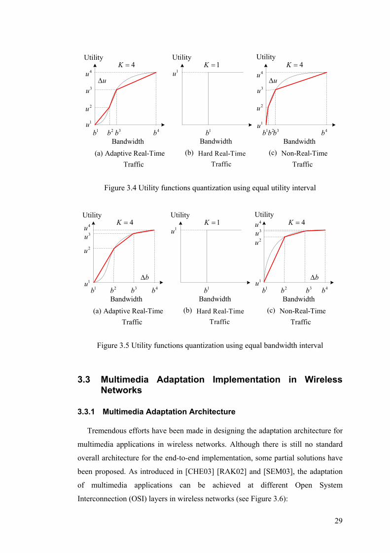
29
4bBandwidth
Utility
1bBandwidth
Utility
1bBandwidth
Utility
4b
(a) (b) (c)Hard Real-Time Traffic
Non-Real-Time Traffic
Adaptive Real-Time Traffic
2b 3b 1b 2b 3b1u
2u
3u
4u
1u
3u
1u
2u
4uu∆ u∆
4=K 1=K 4=K
Figure 3.4 Utility functions quantization using equal utility interval
4bBandwidth
Utility
1bBandwidth
Utility
1bBandwidth
Utility
4b
(a) (b) (c)Hard Real-Time Traffic
Non-Real-Time Traffic
Adaptive Real-Time Traffic
2b 3b 1b 2b 3b1u
2u
3u4u
1u
3u1u
2u
4u
b∆ b∆
4=K 1=K 4=K
Figure 3.5 Utility functions quantization using equal bandwidth interval
3.3 Multimedia Adaptation Implementation in Wireless Networks
3.3.1 Multimedia Adaptation Architecture
Tremendous efforts have been made in designing the adaptation architecture for
multimedia applications in wireless networks. Although there is still no standard
overall architecture for the end-to-end implementation, some partial solutions have
been proposed. As introduced in [CHE03] [RAK02] and [SEM03], the adaptation
of multimedia applications can be achieved at different Open System
Interconnection (OSI) layers in wireless networks (see Figure 3.6):
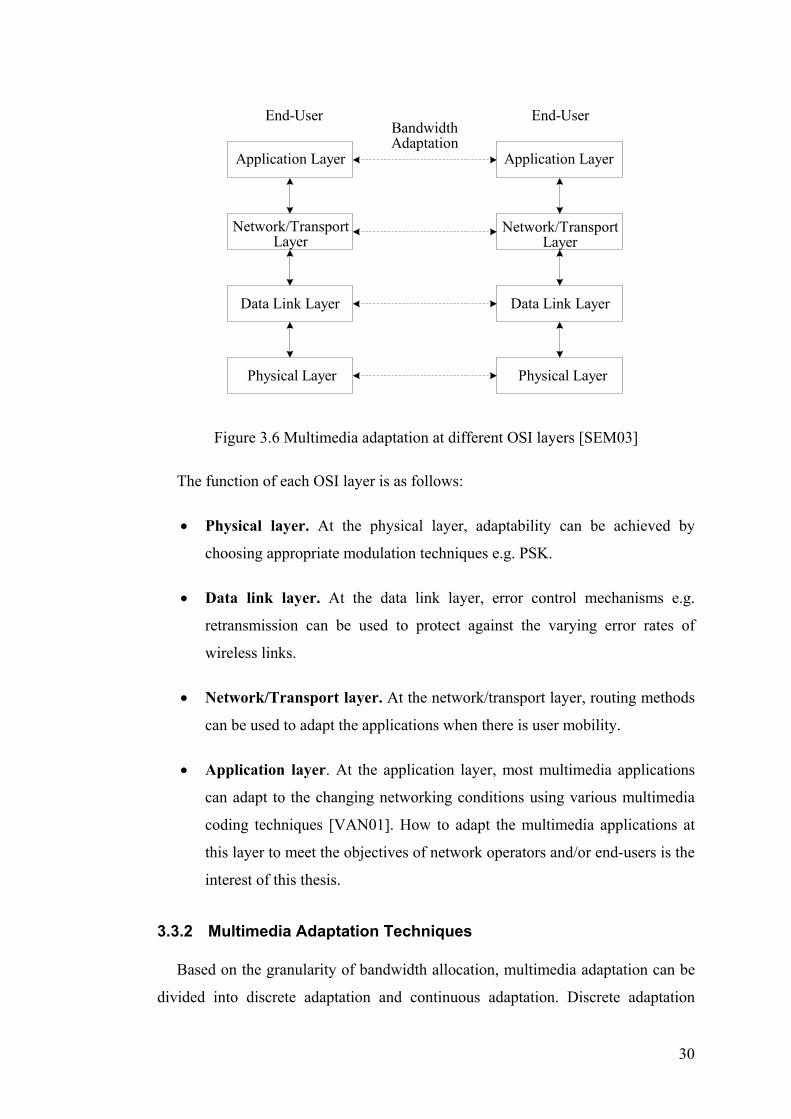
30
End-User End-UserBandwidthAdaptation
Application Layer Application Layer
Network/TransportLayer
Network/TransportLayer
Data Link Layer Data Link Layer
Physical Layer Physical Layer
Figure 3.6 Multimedia adaptation at different OSI layers [SEM03]
The function of each OSI layer is as follows:
• Physical layer. At the physical layer, adaptability can be achieved by
choosing appropriate modulation techniques e.g. PSK.
• Data link layer. At the data link layer, error control mechanisms e.g.
retransmission can be used to protect against the varying error rates of
wireless links.
• Network/Transport layer. At the network/transport layer, routing methods
can be used to adapt the applications when there is user mobility.
• Application layer. At the application layer, most multimedia applications
can adapt to the changing networking conditions using various multimedia
coding techniques [VAN01]. How to adapt the multimedia applications at
this layer to meet the objectives of network operators and/or end-users is the
interest of this thesis.
3.3.2 Multimedia Adaptation Techniques
Based on the granularity of bandwidth allocation, multimedia adaptation can be
divided into discrete adaptation and continuous adaptation. Discrete adaptation

31
limits the bandwidth choice of the application to a set of discrete bit rates between
its minimum and maximum bandwidth requirements, whereas continuous
adaptation allows the allocated bandwidth of the application to be adjusted to any
bit rate between its minimum and maximum bandwidth requirements.
3.3.2.1 Discrete Adaptation
With discrete adaptation approach, the multimedia application is encoded in the
form of different layers to adapt to the varying network resource conditions [LI98]
[SHA92] [VIC98]. The base layer contains critical information for decoding the
application at the lowest quality. The higher layers improve the application quality
progressively. When the network is congested, only the base layer is transmitted;
when more bandwidth becomes available, better application quality can be obtained
by transmitting the higher layers. Figure 3.7 illustrates an example of layer encoded
multimedia. The bandwidth of the multimedia application can only take discrete
values in the set 1 2 3{ , , }b b b . If the network is overloaded, the application is
allocated its base layer bandwidth requirement 1b . When more bandwidth becomes
available, additional bandwidth 1b∆ or 1 2( )b b∆ + ∆ can be allocated increasing the
total bandwidth to 2b or 3b , where 1b∆ and 2b∆ are the 1st and 2nd enhanced
layer of the multimedia application, respectively.
Bandwidth
2b
2b∆
3b1b∆
1b
Figure 3.7 Example of layer encoded multimedia
3.3.2.2 Continuous Adaptation
Discrete adaptation is easy to implement but it has scalability limitation since the
bandwidth of the multimedia application can only be adapted on a number of

32
discrete values. To overcome this drawback, fine-granular scalable (FGS) coding
techniques have been proposed to support continuous multimedia adaptation
[CHE03]. With FGS, the multimedia application can specify the range of
acceptable bandwidth and its allocated bandwidth can be adapted to any value in
the bandwidth range. An example is the wavelet-based Joint Photographic Experts
Group 2000 (JPEG-2000) image coding standard [ISO00-2]. With the embedded
coding system, the image can be encoded at any desirable bit rate within the
specified bandwidth range. The new generation multimedia communication coding
standard MPEG-4 also uses FGS coding to support continuous adaptation [ISO00-
1].
Continuous adaptation provides more control over multimedia applications than
discrete adaptation but it is more complicated to implement. The choice between
discrete and continuous adaptation depends on the needs of network operators
and/or end-users. The bandwidth adaptation schemes described in [KWO02] and
[NAS07] are based on discrete adaptation while the schemes in [BIA98] [CUR05]
and [LIA01] are based on continuous adaptation. Since the utility functions
formulation proposed in Section 3.2.2 assume that the bandwidth of the multimedia
applications are continuous and can take any value between their minimum and
maximum bandwidth requirements, without loss of generality, continuous
multimedia adaptation is considered throughout this thesis.
3.4 Utility-based Bandwidth Adaptation Objectives
Before designing the bandwidth adaptation schemes, it is necessary to identify
the objectives of bandwidth adaptation to decide how bandwidth is allocated among
ongoing calls in the network. For instance, in case of bandwidth scarcity, it is
unclear whether some ongoing calls should be degraded to free bandwidth to
accommodate the new or handoff call, or the new or handoff call should be simply
rejected; if the new or handoff call is chosen for admission, how much each
ongoing call should be degraded and how much bandwidth should be allocated to
the new or handoff call.

33
The objectives of bandwidth adaptation can be very diverse according to the
QoS requirements of network operators and/or end-users. From the network
operators’ perspective, they are usually interested in generating more network
revenue, i.e. utility, while providing good service qualities to attract end-users.
From the end-users’ perspective, they usually want to be treated by network
operators in a fair manner, i.e. their perceived applications qualities are as equal to
each other as possible. To support the QoS provisioning in wireless networks,
bandwidth adaptation often needs to make tradeoffs between multiple QoS
objectives. In this thesis, bandwidth adaptation is based on application utility
functions. Each call in the network is assigned a utility function to reflect the
relationship between bandwidth allocation and the end-user’s satisfaction. The
utility-based bandwidth adaptation takes into account the QoS requirements of
network operators and/or end-users. The later chapters will introduce some
important utility-based bandwidth adaptation objectives and propose corresponding
bandwidth adaptation schemes to meet these objectives.
3.5 Utility-based Bandwidth Adaptation Procedure
In wireless networks with multimedia traffic, bandwidth adaptation should be
used selectively. Since calls belonging to hard real-time traffic have stringent
bandwidth requirements and their allocated bandwidth cannot be changed after they
are admitted into the network, bandwidth adaptation can only be applied to adaptive
calls, i.e. calls belonging to adaptive real-time traffic or non-real-time traffic1.
Bandwidth adaptation is performed in each BS and it consists of two processes –
bandwidth degrades and bandwidth upgrades, which are triggered by call arrival
events and call departure events, respectively (see Figure 3.8). Call arrival events
include new call arrival events (a new call is generated within the cell) and handoff
call arrival events (a handoff call arrives to the cell). Call departure events include
call completion events (a call within the cell completes) and outgoing handoff
events (a call leaves its current cell) [ALJ00] [XIA01].
1 Throughout this thesis, adaptive calls refer to the calls belonging to adaptive real-time traffic or non-real-time traffic.

34
BandwidthAdaptation
New Call Arrival
Call Completion
Handoff Call Arrival Outgoing Handoff
Figure 3.8 Bandwidth adaptation trigger events
3.5.1 Bandwidth Degrades
When a new or handoff call arrives to a cell of the network, if the cell has
enough bandwidth available, the new or handoff call is admitted at its maximum
bandwidth requirement. If the cell is overloaded, the bandwidth of adaptive ongoing
calls can be degraded to smaller values to accommodate the new or handoff call. To
meet the utility-based objectives specified by network operators and/or end-users,
bandwidth degrades need to answer three questions: 1) which ongoing calls are
eligible to degrade; 2) how much each ongoing call should be degraded; and 3) how
much bandwidth should be allocated to the new or handoff call. Figure 3.9
illustrates the bandwidth degrades procedure when a new or handoff call arrives to
a cell containing n adaptive ongoing calls, where curib and adapt
ib are the current
bandwidth allocation and the bandwidth allocation after bandwidth degrades of the
-thi ongoing call, respectively.
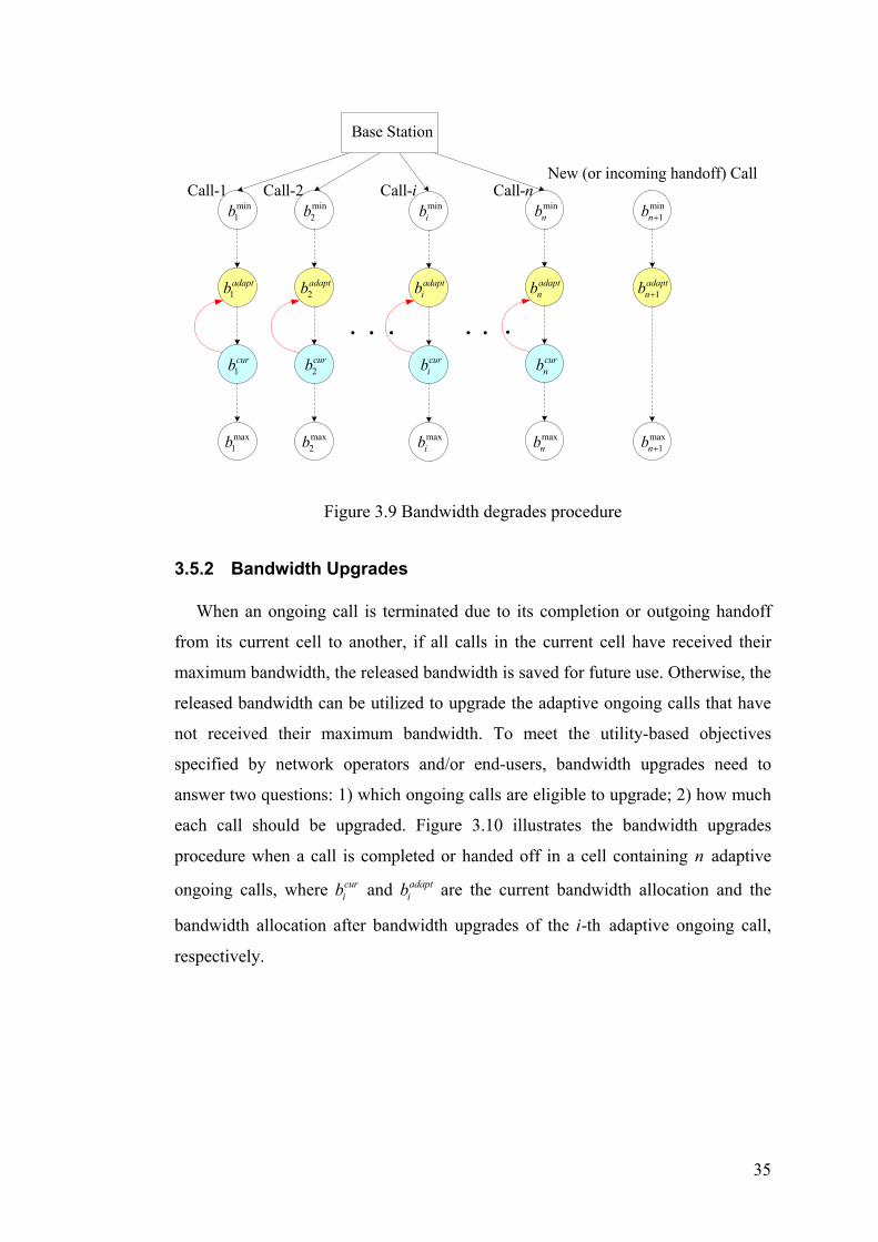
35
min1b
1adaptb
max1b
1curb
min2b
2adaptb
max2b
2curb
minib
adaptib
maxib
curib
minnb
adaptnb
maxnb
curnb
min1nb +
1adaptnb +
max1nb +
Call-1 Call-2 Call-nNew (or incoming handoff) Call
Base Station
Call-i
Figure 3.9 Bandwidth degrades procedure
3.5.2 Bandwidth Upgrades
When an ongoing call is terminated due to its completion or outgoing handoff
from its current cell to another, if all calls in the current cell have received their
maximum bandwidth, the released bandwidth is saved for future use. Otherwise, the
released bandwidth can be utilized to upgrade the adaptive ongoing calls that have
not received their maximum bandwidth. To meet the utility-based objectives
specified by network operators and/or end-users, bandwidth upgrades need to
answer two questions: 1) which ongoing calls are eligible to upgrade; 2) how much
each call should be upgraded. Figure 3.10 illustrates the bandwidth upgrades
procedure when a call is completed or handed off in a cell containing n adaptive
ongoing calls, where curib and adapt
ib are the current bandwidth allocation and the
bandwidth allocation after bandwidth upgrades of the -thi adaptive ongoing call,
respectively.

36
min1b
1curb
max1b
1adaptb
min2b
2curb
max2b
2adaptb
minib
curib
maxib
minnb
curnb
maxnb
adaptnb
Call-1 Call-2 Call-i Call-n
Terminated (or outgoing handoff) CallBase Station
Figure 3.10 Bandwidth upgrades procedure
3.6 Summary
This chapter introduces the fundamental issues of utility-based bandwidth
adaptation for multimedia wireless networks. First, the utility-based adaptive
multimedia traffic model is presented by classifying multimedia traffic into
different classes and formulating the utility function for each class of traffic
according to its adaptive characteristics. Then the network architecture of
multimedia adaptation is introduced. Two multimedia adaptation techniques, i.e.
discrete adaptation and continuous adaptation are presented. At the end, the
objectives of utility-based bandwidth adaptation are discussed and the bandwidth
adaptation procedure including bandwidth degrades and bandwidth upgrades are
described in detail.

37
Chapter 4 Utility-Maximization Bandwidth Adaptation
4.1 Introduction
As described in Chapter 3, from the network operators’ perspective, the most
important objective of bandwidth adaptation is to achieve higher network utility
while providing good applications qualities. The network utility can be increased by
accommodating more calls and/or allocating bandwidth among calls using the
utility-maximization approach. Since admitting too many calls into the network can
cause the network overload and result in severe applications degradation, this
chapter investigates the method to allocate bandwidth to maximize the total utility
of all calls in the network. Building on the availability of utility-based adaptive
traffic model, a utility-maximization bandwidth adaptation scheme is proposed for
multimedia traffic in wireless networks. Apart from the utility-maximization
bandwidth adaptation algorithm, two supplementary resource management
functionalities including CAC and bandwidth reservation has also been integrated
into the bandwidth adaptation scheme to reduce the call blocking and handoff
dropping probabilities.
The structure of the chapter is as follows. Section 4.2 surveys related work in the
area of utility-maximization bandwidth adaptation for wireless networks and shows
that the proposed scheme is new and original. Section 4.3 gives a detailed
description and formulation of the utility-maximization bandwidth adaptation
problem. Section 4.4 presents an efficient search tree based algorithm to maximize
the total utility of ongoing calls in the network. Section 4.5 introduces the CAC and
bandwidth reservation mechanisms which provide QoS guarantees to the new and
handoff calls. Section 4.6 presents the multimedia wireless network simulation
model used in this thesis. Section 4.7 verifies and validates the simulation model.
Section 4.8 evaluates the performance of the proposed utility-maximization
bandwidth adaptation scheme by comparing it with a non-adaptive scheme and
RBBS under various traffic loads. Section 4.9 summarizes the chapter.

38
4.2 Related Work
Recently some utility-maximization bandwidth adaptation schemes have been
proposed for the QoS provisioning in wireless networks. Reference [BHA98]
presents the TIMELY adaptive resource management architecture for wireless
networks. The architecture has four layers – link, reservation, adaptation and
transport – all of which perform resource adaptation in a coordinated manner to
solve the problems introduced by the scarce and dynamic network resources. A
revenue model for resource usage is described and a rate adaptation algorithm is
presented to distribute resource among the adaptable flows to maximize network
revenue. However, the multi-layer architecture has made the bandwidth adaptation
to work at the expense of high message overhead. In [DAS03], the authors
introduce a bandwidth adaptation scheme for multimedia wireless networks. A
revenue-based multimedia traffic model is introduced and a bandwidth degradation
algorithm is presented to maximize the net revenue of the network. Kwon et al.
[KWO02] describes a near-optimal bandwidth allocation algorithm for multimedia
QoS support in wireless networks. When the network is overloaded, bandwidth can
be degraded from ongoing calls to accept the new or handoff call. The bandwidth
degradation algorithm is based on a greedy approach and seeks to achieve
maximum network revenue with polynomial time complexity. The limitation of
[DAS03] and [KWO02] is that they only consider wireless networks with one
single cell thus the basic characteristic of wireless networks, i.e. user mobility, has
not been taken into account. The authors in [FEI06] propose a bandwidth adaptation
scheme for wireless networks with multiple cells. The QoS provisioning is
formulated as a constrained Markov decision problem and a Q-learning algorithm is
introduced to maximize the network revenue and meet the QoS constraints. But the
learning process of the algorithm can be time-consuming making it not suitable for
real-time QoS support. Another bandwidth adaptation scheme for multiple cells
wireless networks is described in [AHN03]. When some bandwidth becomes
available due to the completion or outgoing handoff of an ongoing call, the released
bandwidth is utilized to upgrade other ongoing calls which need more bandwidth
allocation. The objective of bandwidth upgrades is to maximize the total
satisfaction degree of end-users in the network. A Lagrangean relaxation based
algorithm is developed to support the real-time bandwidth adaptation. The

39
drawback of the scheme is that it does not address the problem of bandwidth
degradation when the network is overloaded. In the work of Curescu et al.
[CUR05], a time-aware bandwidth allocation scheme is introduced for wireless
networks to maximize the accumulated utility of all ongoing calls. Interestingly, the
scheme identifies how bandwidth re-allocation affects the utilities of the
applications. To integrate this information into the bandwidth allocation algorithm,
it is assumed that the duration of every connection can be estimated. However,
under real-time wireless networks environment it is complicated to estimate the
connection duration since the allocated bandwidth of ongoing calls are changed
dynamically with bandwidth adaptation. Moreover, the scheme does not reserve
bandwidth for real-time handoff calls therefore it risks an inability of meeting their
QoS requirements when the network is heavily overloaded. Bandwidth reservation
has also been ignored by [AHN03] [DAS03] [FEI06] and [KWO02].
This chapter proposes a novel utility-maximization bandwidth adaptation
scheme for QoS support in multimedia wireless networks. With the proposed
scheme, each call in the network is assigned a utility function. Bandwidth
adaptation is divided into two processes – bandwidth degrades and bandwidth
upgrades. Depending on the network load the allocated bandwidth of ongoing calls
are degraded or upgraded dynamically so that the achieved utility in each individual
cell of the network is maximized. Appropriate CAC and bandwidth reservation
policies have also been integrated into the bandwidth adaptation scheme to reduce
the call blocking and handoff dropping probabilities.
4.3 Problem Formulation
As introduced in Chapter 3, bandwidth adaptation is performed based on each
cell of the network in a distributed manner and it is assumed that the bandwidth
capacity of each cell is fixed.
4.3.1 Bandwidth Degrades
Consider a saturated cell containing n adaptive ongoing calls, when a new or
handoff call arrives the allocated bandwidth of ongoing calls can be degraded to
smaller values to accommodate the new or handoff call. Denote the utility function

40
of the -thi ongoing call as ( )i iu b (1 )i n≤ ≤ and its current allocated bandwidth as
iβ , thus the degradable utility function of the -thi ongoing call can be written as
( ) ( )β↓ ↓ ↓= −i i i i iu b u b min(0 )i i ib bβ↓≤ ≤ − , where ib↓ and minib are the bandwidth
degrades and the minimum bandwidth requirement of the call, respectively. Figure
4.1 illustrates the degradable utility function of the -thi ongoing call when it
belongs to adaptive real-time traffic or non-real-time traffic.
maxbBandwidth
Utility
1
minb0
Bandwidth
Utility
maxb
1
0iβ iβ
( )i iu b
( )i iu b↓ ↓( )i iu b↓ ↓
(b) Non-real-time Traffic(a) Adaptive Real-Time Traffic
( )i iu b
Figure 4.1 The degradable utility function of the -thi ongoing call
Assume the new or handoff call is adaptive2 and denote its utility function as
1 1( )n nu b+ + . The objective of bandwidth degrades is to find the bandwidth degrades
profile { }ib↓ for the n ongoing calls and the allocated bandwidth 1nb + for the new
or handoff call to maximize their total utility subject to bandwidth constraints, i.e.
maximize 1 11
( ) ( )↓ ↓+ +
=
+
∑
n
i i n ni
u b u b , (4.1)
subject to min0 i i ib bβ↓≤ ≤ − , (4.2)
11
( )n
i i ni
b b Bβ ↓+
=
− + ≤
∑ . (4.3)
2 If the new or handoff call is non-adaptive, it is not considered for bandwidth adaptation and its acceptance or rejection is determined by the CAC policy introduced later.

41
where B is the total available bandwidth for adaptive calls.
Note that bandwidth degrades are only performed among adaptive ongoing calls.
Calls belonging to hard-real-time traffic cannot be degraded since for these calls
any bandwidth degrades will cause them to be dropped due to their stringent
bandwidth requirements.
4.3.2 Bandwidth Upgrades
Assume that in an overloaded cell when a call is completed or handed off to
another cell, there are n adaptive ongoing calls that have not received their
maximum bandwidth requirements. The released bandwidth from the completed or
outgoing handoff call (denoted by β ) can be used to upgrade these ongoing calls to
enhance their qualities and increase network bandwidth utilization. Again, denote
the utility function of the -thi ongoing call as ( )i iu b (1 )≤ ≤i n and its current
allocated bandwidth as iβ , thus the upgradable utility function of the -thi ongoing
call can be written as ( ) ( )i i i i iu b u bβ↑ ↑ ↑= + max(0 )i i ib b β↑≤ ≤ − , where ib↑ and maxib
are the bandwidth upgrades and the maximum bandwidth requirement of the call,
respectively. Figure 4.2 illustrates the upgradable utility function of the -thi
ongoing call when it belongs to adaptive real-time traffic or non-real-time traffic.
maxbBandwidth
Utility
1
minb0
Bandwidth
Utility
maxb
1
0iβ iβ
( )i iu b
( )i iu b↑ ↑ ( )i iu b↑ ↑
(b) Non-real-time Traffic(a) Adaptive Real-Time Traffic
( )i iu b
Figure 4.2 The upgradable utility function of the -thi ongoing call

42
The objective of bandwidth upgrades is to find the bandwidth upgrades profile
{ }ib↑ for the n ongoing calls to maximize their total utility subject to bandwidth
constraints, i.e.
maximize 1
( )n
i ii
u b↑ ↑
=∑ , (4.4)
subject to max0 i i ib b β↑≤ ≤ − , (4.5)
1
n
ii
b β↑
=
≤∑ . (4.6)
Similar to bandwidth degrades, bandwidth upgrades are also only performed
among adaptive ongoing calls. Calls belonging to hard-real-time traffic do not need
to be upgraded because for these calls more bandwidth allocation will not lead to
extra utility generation.
4.4 The Proposed Utility-Maximization Algorithm
The essence of utility-maximization bandwidth adaptation is to maximize the
total utility of n utility functions subject to bandwidth constraints. In Chapter 3
utility function quantization is introduced to simplify the utility function. For utility
function ( )i iu b , after quantization using equal bandwidth interval b∆ or equal
utility interval u∆ it becomes a function represented by a list of <bandwidth,
utility> points in the increasing order of bandwidth, i.e.
1 1 2 2( ) ( , , , , , , )i iK Ki i i i i i i iu b b u b u b u= < > < > < >…
where iK is the maximum <bandwidth, utility> level. Thus bandwidth adaptation
becomes to maximize the total utility of n quantized utility functions which can be
arranged as follows:
1 11 1 2 21 1 1 1 1 1 1 1( ) ( , , , , , , )K Ku b b u b u b u= < > < > < >…
2 21 1 2 22 2 2 2 2 2 2 2( ) ( , , , , , , )K Ku b b u b u b u= < > < > < >…

43
1 1 2 2( ) ( , , , , , , )n nK Kn n n n n n n nu b b u b u b u= < > < > < >…
The utility-maximization problem is NP-hard and finding optimal solutions has
exponential time complexity [CUR05] [LEE99]. In wireless networks bandwidth
adaptation should be performed in real-time to support the frequent bandwidth
fluctuations. Therefore in this section an efficient search tree based utility-
maximization algorithm is presented.
The algorithm can be illustrated by a search tree as shown in Figure 4.3. The
quantized utility function of each call is represented by a branch in the tree and the
<bandwidth, utility> points of each utility function are represented by the nodes in
the branch. The nodes of each branch are laid out downwards to reflect the
bandwidth allocation order, i.e. the second <bandwidth, utility> point of a utility
function is connected to its first <bandwidth, utility> point and so on.
11b
11lb
11Kb
11mb
11u
11lu
11mu
11Ku
12b
22lb
22Kb
22mb
12u
22lu
22mu
22Ku
1ib
ilib
iKib
imib
1iu
iliu
imiu
iKiu
1nb
nlnb
nKnb
nmnb
1nu
nlnu
nmnu
nKnu
1curb
1nextb
2curb
2nextb
curib
nextib
curnb
nextnb
Start
Figure 4.3 Bandwidth allocation tree
The tree contains n branches and the number of branches is equal to the number
of utility functions. Each branch (utility function) is associated with ten variables

44
curib , cur
iu , nextib , next
iu , tempib , temp
iu , reqib , cur
ir , tempir and max
ir (all notations can be
found in Table 4.1). The algorithm allocates the bandwidth in a greedy fashion
based on utility generation ratio, i.e. it gives priority to the <bandwidth, utility>
points with higher utility generation ratio. The utility generation ratio r is
calculated by dividing the utility increase by bandwidth increase between two
<bandwidth, utility> points in a branch. The pseudo-code of the algorithm is as
follows:
Table 4.1 Notations for the utility-maximization algorithm
B the total available bandwidth to be allocated availb the current available bandwidth to be allocated curib the current bandwidth allocation of the -thi call curiu the current achieved utility of the -thi call nextib the next possible bandwidth allocation of the -thi call nextiu the next possible achieved utility of the -thi call tempib the temporary bandwidth allocation of the -thi call tempiu the temporary achieved utility of the -thi call reqib the required bandwidth for upgrading the current bandwidth allocation
of the -thi call to its next higher bandwidth level , maxreqb the maximum req
ib among all calls, i.e. , max max{ }req reqib b= (1 )i n≤ ≤
curir the current utility generation ratio of the -thi call temp
ir the temporary utility generation ratio of the -thi call max
ir the maximum utility generation ratio of the -thi call
Utility-maximization algorithm:
(1) availb B= for each call-i
initialize curib , cur
iu , nextib , next
iu , tempib and temp
iu to be at the first level 1req cur cur
i i ib b b+= − 1( ) /cur cur cur req
i i i ir u u b+= − 0temp
ir = max 0ir =
(2) for each call-i while ( )iKtemp
i ib b< 1temp temp
i ib b += ( ) /( )temp temp cur temp cur
i i i i ir u u b b= − − if max( )temp
i ir r>

45
next tempi ib b=
max tempi ir r=
(3) among all calls find the largest reqib denoted by , maxreqb
if , max( )avail reqb b≤ among all calls with req avail
ib b≥ find the call with the highest curir denoted
by call-k cur cur avail
k kb b b= + return cur
ib as the bandwidth allocation for each call (4) among all calls find the call with the largest max
ir denoted by call-j if ( ( ))≥ −avail next cur
j jb b b
( )avail avail next curj jb b b b= − −
cur nextj jb b=
temp nextj jb b=
0tempjr =
max 0jr =
if ( )jKcurj jb b<
1req cur curj j jb b b+= −
1( ) /cur cur cur reqj j j jr u u b+= −
else 0req
jb =
0curjr =
else cur cur avail
j jb b b= +
return curib as the bandwidth allocation for each call
(5) for call-j found in Step (4) while ( )jKtemp
j jb b<
1temp tempj jb b +=
( ) /( )temp temp cur temp curj j j j jr u u b b= − −
if max( )tempj jr r>
next tempj jb b=
max tempj jr r=
(6) Go to Step (3)
In Step (1), for each call the algorithm initializes its associated variables and
calculates the required bandwidth for upgrading the call to the next higher
bandwidth level reqib and the current utility generation ratio cur
ir .

46
In Step (2), for each call the algorithm increases its temporary bandwidth
allocation tempib by one level and then calculates its temporary utility generation
ratio tempir . If temp
ir is greater than the maximum utility generation ratio maxir the
algorithm upgrades its next possible bandwidth allocation nextib to temp
ib and assigns
tempir to max
ir . The above process is repeated until every node of the branch has been
investigated and the node with the maximum utility generation ratio is the next
possible bandwidth allocation node of the corresponding call.
Step (3) checks if the current available bandwidth availb is less than or equal to
the maximum required bandwidth , maxreqb . If the answer is yes, then availb is
allocated to the call with the highest current utility generation ratio curir among all
calls with req availib b≥ , and the algorithm terminates; otherwise, the algorithm
proceeds to Step (4).
In Step (4), the algorithm keeps track of the maximum utility generation ratio max
ir of each call. It finds the call with the highest maxir denoted as call-j . If there is
enough bandwidth available the algorithm upgrades its current bandwidth allocation curjb and temporary bandwidth allocation temp
jb to its next possible bandwidth
allocation nextjb ; otherwise, the current available bandwidth availb is allocated to
call-j and the algorithm terminates.
Subsequently, for call-j it has the same current and next possible bandwidth
allocation. Therefore, in Step (5) the algorithm updates its next possible bandwidth
allocation using the same approach as described in Step (2).
After finding the new next possible bandwidth allocation for call-j , the
algorithm goes back to Step (3) to execute the above procedure repeatedly until it
terminates due to insufficient bandwidth (it is assumed that the total available
bandwidth B cannot satisfy the maximum bandwidth requirements of all calls).

47
4.5 CAC and Bandwidth Reservation
To provide QoS guarantees for multimedia traffic in wireless networks, the stand
alone usage of the utility-maximization bandwidth adaptation algorithm is not
enough, two supplementary bandwidth management functionalities, i.e. CAC and
bandwidth reservation, need to be incorporated into the proposed bandwidth
adaptation scheme [NAS04].
With CAC policy, when a new call requests admission into the network, the cell
first attempts to allocate the maximum bandwidth requirement to the new call. If
there is enough bandwidth available in the cell, the CAC accepts the new call by
assigning it the maximum bandwidth requirement. If there is not enough
bandwidth, the bandwidth adaptation algorithm is invoked to free some bandwidth
from the existing ongoing calls. After bandwidth adaptation if the sum of the
available bandwidth in the cell plus the freed bandwidth according to the bandwidth
adaptation algorithm is greater than or equal to the desired bandwidth requirement3
of the new call, the new call is admitted; otherwise, the new call is blocked.
The objective of CAC is to admit new calls and handoff calls as much as
possible under the guidance of utility-maximization bandwidth adaptation
algorithm. But new calls and handoff calls are competing for the usage of the finite
network bandwidth. It is well known and obvious that, from the end-users’
perspective, the dropping of a handoff call during its service session is much more
unbearable than the blocking of a new call at its beginning. Based on this fact, some
bandwidth can be reserved for handoff calls to reduce their dropping probability.
However, bandwidth reservation should be used carefully since it may decrease the
bandwidth utilization of the network. The proposed bandwidth reservation policies
differentiate between Class I (real-time) and Class II (non-real-time) traffic. A
certain amount of bandwidth is reserved exclusively for Class I traffic because real-
time traffic would suffer an actual loss by being dropped. The reserved bandwidth
is not available to Class II traffic because it is assumed that a Class II call, although
3 The desired bandwidth requirement of the call will be introduced later in the simulation traffic model.

48
inconvenienced by being dropped, would be able to resume its transmission at a
later time without any significant loss due to its elastic characteristics.
When a handoff call requests admission into the network, the cell first attempts
to allocate the maximum bandwidth requirement to the handoff call. If there is
enough bandwidth available in the cell, the CAC accepts the handoff call by
assigning it the maximum bandwidth requirement. If there in not enough
bandwidth, the bandwidth adaptation algorithm is invoked to free some bandwidth
from the existing ongoing calls. After bandwidth adaptation, the CAC checks the
traffic class that the handoff call belongs to. If the handoff call belongs to traffic
Class I and the sum of the available bandwidth in the cell plus the freed bandwidth
according to the bandwidth adaptation algorithm plus the available reserved
bandwidth is greater than or equal to the minimum bandwidth requirement of the
handoff call, the handoff call is admitted; otherwise, the handoff call is dropped. If
the handoff call belongs to traffic Class II, it is accepted as long as there is some
bandwidth available after bandwidth adaptation; it will only be dropped when there
is no bandwidth available at all.
Note that to give higher priority to handoff calls over new calls the CAC admits
new calls more strictly than handoff calls. A new call is only accepted when its
desired bandwidth requirement can be met whereas a handoff call is accepted as
long as its minimum bandwidth requirement can be provided.
After a call is completed or handed off from a current cell to another, if the call
is a new call when admitted into the current cell, its released bandwidth is utilized
to upgrade other ongoing calls or saved for future usage depending on whether
there are any ongoing calls served with bandwidth less than the maximum
bandwidth requirements. If the call is a handoff call when admitted into the current
cell, its released reserved bandwidth (if there is any) is returned to the reserved
bandwidth pool for future incoming handoff calls and its released cell bandwidth (if
there is any) is used to upgrade other ongoing calls or saved for future usage
depending on whether there are any ongoing calls served with bandwidth less than
the maximum bandwidth requirements.

49
The pseudo-code for handling call arrivals and departures is described as follows
and the notations can be found in Table 4.2.
Table 4.2 Notations for handling call arrivals and departures
_avail cellb the current available cell bandwidth to be allocated _avail reservedb the current available reserved bandwidth to be allocated
minb the minimum bandwidth requirement of the call maxb the maximum bandwidth requirement of the call desiredb the desired bandwidth requirement of the call degradesb the freed bandwidth after performing bandwidth degrades upgradesb the consumed bandwidth after performing bandwidth upgrades
_released cellb the released cell bandwidth after a call is terminated due to its completion or outgoing handoff
_released reservedb the released reserved bandwidth after a call is terminated due to its completion or outgoing handoff
Algorithm for handling call arrivals and departures:
New call arrival:
if _ max( )avail cellb b≥ assign maxb to the new call; _ _ maxavail cell avail cellb b b= − ; else perform bandwidth degrades; if _ desired( )avail cell degradesb b b+ ≥ assign _( )avail cell degradesb b+ to the new call; _ 0avail cellb = ; else reject the new call;
Handoff call arrival:
if _ max( )avail cellb b≥ assign maxb to the handoff call; _ _ maxavail cell avail cellb b b= − ; else perform bandwidth degrades; if (is Class I call) if _ min( )avail cell degradesb b b+ ≥ assign _( )avail cell degradesb b+ to the handoff call; _ 0avail cellb = ; else if _ _ min( )avail cell degrades avail reservedb b b b+ + ≥

50
assign minb to the handoff call; _ 0avail cellb = ; _ _ min _( ( ))avail reserved avail reserved avail cell degradesb b b b b= − − + ; else reject the handoff call; else // is Class II call if _( 0)avail cell degradesb b+ > assign _( )avail cell degradesb b+ to the handoff call; _ 0avail cellb = ; else reject the handoff call;
Call departures:
if (is new call when admitted) if (every call has received maxb ) _ _ _= +avail cell avail cell released cellb b b ; else perform bandwidth upgrades; _ _ _avail cell avail cell released cell upgradesb b b b= + − ; else // is handoff call when admitted _ _ _avail reserved avail reserved released reservedb b b= + ; if (every call has received maxb ) _ _ _avail cell avail cell released cellb b b= + ; else perform bandwidth upgrades; _ _ _avail cell avail cell released cell upgradesb b b b= + − ;
4.6 Simulation Modelling
To evaluate the performance of the proposed utility-maximization bandwidth
adaptation scheme, a multimedia wireless network simulation model has been
developed.
4.6.1 Network Model
The simulated network consists of 36 (6×6) hexagonal cells. The diameter of
each cell is 1 km and each cell has a total bandwidth capacity of 30 Mbps. The
layout of the simulation network is shown in Figure 4.4. To avoid the edge effect of
the finite network size, wrap-around is applied to the edge cells so that each cell has
six neighbouring cells.

51
0 1 2 3 4 5
6 7 8 9 10 11
12 13 14 15 16 17
18 19 20 21 22 23
24 25 26 27 28 29
30 31 32 33 34 35
Figure 4.4 The layout of the wireless network model
4.6.2 Traffic Model
Six representative groups of multimedia traffic belonging to the two traffic
classes, i.e. real-time traffic (Class I) and non-real-time traffic (Class II), are
considered in the simulation. They are typical traffic seen in multimedia wireless
networks and similar traffic have been used by previous work [AHN03] [CHA06]
[CUR05] [ELK02] [OLI98]. Each group of traffic is associated with a utility
function and all calls belonging to the same traffic group are assumed to have the
same bandwidth requirements and utility function. The exact characteristics of the
traffic are shown in Table 4.3. To allow the fair comparison between the proposed
bandwidth adaptation scheme and RBBS, the minimum/maximum bandwidth
requirements and average connection duration of all traffic groups are taken directly
from [ELK02]. Traffic groups 0 and 1 belong to hard real-time traffic, according to
the utility functions formulation in Chapter 3 their utility functions is determined
from minb and maxu , where max 1u = . Traffic group 2 belongs to adaptive real-time
traffic, the two parameters 1k and 2k of its utility function are calculated from intrb ,
maxb and maxu , where intrb is set to be 1.5 and maxu is set to be 0.99. Traffic groups
3, 4 and 5 belong to non-real-time traffic and the parameter k of their utility
functions are derived from maxb and maxu , where maxu is also set to be 0.99. In fact,

52
for traffic groups 2 to 5, maxu can be chosen to be any value very close to 1
according to the preference of network operators and/or end-users without major
difference to the performance results. For each traffic group, the desired bandwidth
requirement desiredb is defined as the bandwidth which enables its utility function to
receive half of maxu . Since traffic groups 0 and 1 are hard real-time traffic, their
desired bandwidth requirements are equal to their maximum bandwidth
requirements.
Table 4.3 Traffic characteristics for the simulation
App. Group
Traffic Class
Bandwidth Requirement
(Mbps)
Average Connection
Duration
Example Utility Function
( b is Mbps) 0 I
(Hard Real-Time)
min 0.03b = desired 0.03b =
3 minutes Voice Service & Audio Phone
1, 0.030, 0.03
bb≥
<
max 1u =
1 I (Hard Real-
Time)
min 0.25b = desired 0.25b =
5 minutes Video Phone & Video Conference
1, 0.250, 0.25
bb≥
<
max 1u =
2 I (Adaptive
Real-Time)
min 1b = intr 1.5b = desired 2b =
max 6b =
10 minutes Interact. Multimedia &
Video on Demand
21.88.31
bbe
−+−
max 0.99u =
3 II (Non-Real-
Time)
min 0b = desired 0.003b =
max 0.02b =
30 seconds E-mail, Paging & Fax
4.60.021
b
e−
− max 0.99u =
4 II (Non-Real-
Time)
min 0b = desired 0.1b = max 0.5b =
3 minutes Remote Login & Data on Demand
4.60.51
b
e−
− max 0.99u =
5 II (Non-Real-
Time)
min 0b = desired 1.5b =
max 10b =
2 minutes File Transfer & Retrieval Service
4.6101
b
e−
− max 0.99u =
The traffic is generated in the following way. New call arrivals of group-i
( 1, 2, , 6)= …i traffic are assumed to follow Poisson distribution with mean rate newiλ and all six groups of traffic are generated with equal probability, i.e.

53
1 2 6new new newλ λ λ= = = . Handoff call arrivals of group-i traffic are assumed to be
proportional to the new call arrivals by handoff newi iλ αλ= , where α is set to be 0.5 in
the experiments. The call holding time (CHT) of group-i traffic is assumed to
follow exponential distribution with mean 1/ iµ . It should be noted that for Class II
traffic (groups 3, 4 and 5) the CHT is difficult to be pre-defined since it depends on
not only the service size (e.g. transferred file size) but also the allocated bandwidth
of the call which changes dynamically with bandwidth adaptation. For the sake of
simplicity, like in [ELK02] and [OLI98] it is assumed that Class II calls have fixed
duration. After a call is disconnected at the end of its service session, the service
can be continued by a new request in the future without significant performance
loss. For the mobility characterization, the cell residence time (CRT), i.e. the
amount of time during which a group-i call stays in a cell before handoff, is
assumed to follow an exponential distribution with mean 1/ iη [NAS07] [YEU96].
4.6.3 Simulator
The simulator employs discrete-event simulation to model the traffic and its
management in wireless networks. A discrete-event simulation is one in which the
state of the model changes at only a discrete set of simulated time points. With
discrete event simulation a real network system is decomposed into a set of separate
components. The fundamental element of the simulation is event and the operation
of the system is represented as a chronological sequence of events. Each event is
assigned a time stamp and takes place on a specific component. The result of this
event can be a message passed to one or more other components. On arrival at the
other components, the content of the message may result in the generation of new
events to be processed at some future logical time. The simulator mainly consists of
three components: MT, traffic manager and network resource manager.
4.6.3.1 MT
MTs are the entities responsible for generating traffic events. A MT is able to
generate four types of events that constitute the traffic of the simulator.
• NEW_CALL_REQUEST: the request to connect a new call;

54
• HANDOFF_CALL_REQUEST: the request to connect a handoff call;
• INFORM_HANDOFF: an inform-type message that an ongoing call is
handed off from its current cell;
• INFORM_COMPLETION: an inform-type message that an ongoing call is
completed.
The NEW_CALL_REQUEST and HANDOFF_CALL_REQUEST events carry
the traffic characteristics of the call, i.e. its traffic group/class, bandwidth
requirements and utility function.
4.6.3.2 Traffic Manager
The role of the traffic manager is to handle the traffic events generated by the
MTs. The traffic manager is designed to work in a centralized manner and it acts as
a gateway between all MTs and the network. The centralized approach involves
more message overhead than the distributed one, but it has greatly simplified the
traffic management of the simulator. Upon receiving a traffic event from the MT,
the traffic manager tries to find a cell which covers the location where the traffic
event is generated. If there is no coverage cell, the traffic manager replies with a
reject event to the MT. Otherwise, the traffic manager dispatches the traffic event to
the network resource manager of the coverage cell. After receiving the responses
from the network resource manager, the traffic manager forwards the response to
the MT.
4.6.3.3 Network Resource Manager
The network resource manager is responsible for allocating the bandwidth
resource of the network to the calls. After receiving a NEW_CALL_REQUEST or
HANDOFF_CALL_REQUEST event from the traffic manager, the network
resource manager extracts the traffic characteristics from the request event and
allocates bandwidth to the call using the embedded bandwidth allocation scheme. If
the bandwidth allocation can satisfy the requested bandwidth of the call, the
network resource manager connects the call by deducting the corresponding
bandwidth from the network and replying to the traffic manager with an
ACCEPT_NEW_CALL or ACCEPT_HANDOFF_CALL event. Otherwise, the

55
network resource manager replies the traffic manager with a
REJECT_NEW_CALL or REJECT_HANDOFF_CALL event. After receiving an
INFORM_HANDOFF or INFORM_COMPLETION event from the traffic
manager, the network resource manager disconnects the ongoing call by returning
its occupied bandwidth to the network and replying the traffic manager with an
ACCEPT_HANDOFF or ACCEPT_ COMPLETION event.
4.6.3.4 Call Setup Sequence
Within the simulator the complete set up sequence of a new or handoff call
request is described as follows:
1. The MT generates a NEW_CALL_REQUEST or
HANDOFF_CALL_REQUEST event and dispatches it to the traffic
manager.
2. The traffic manager tries to find a cell which covers the location where the
traffic event is generated. If there is no coverage cell, the traffic manager
replies the MT with a REJECT_NEW_CALL or
REJECT_HANDOFF_CALL event. If the traffic manager finds a coverage
cell, it dispatches the call request event to the network resource manager of
the coverage cell.
3. After receiving the call request event from the traffic manager, the network
resource manager performs bandwidth adaptation. If the network resource
manager can allocate enough bandwidth to the call, it connects the call and
replies the traffic manager with an ACCEPT_NEW_CALL or
ACCEPT_HANDOFF_CALL event. Otherwise, the network resource
manager replies the traffic manager with a REJECT_NEW_CALL or
REJECT_HANDOFF_CALL event.
4. The traffic manager returns the event received from the network resource
manager (if the call request is accepted, it is ACCEPT_NEW_CALL or
ACCEPT_HANDOFF_CALL event; if the call request is rejected, it is
REJECT_NEW_CALL or REJECT_HANDOFF_CALL event) and informs

56
the MT that originally generates the call request event about the acceptance
or rejection of the call request.
4.7 Simulation Verification and Validation
One of the most important aspects in developing the simulation model is its
credibility. In order to determine whether the multimedia wireless network
simulation model developed accurately represents a real system, simulation
verification and validation is needed. Verification determines whether the
simulation model performs as intended and validation determines whether the
conceptual simulation model is an accurate representation of the system under
study. If the simulation model and its results are valid and are used as an aid in
making decisions, then the model is said to be credible [LAW06].
4.7.1 Verification
The simulation model was verified during the development of the simulator. The
components of the simulator were debugged with the help of traces and breakpoints
as they are written. The results from some particular states were printed out to
check the consistency and coherency of the simulator.
4.7.2 Validation
A valuable approach for simulation validation is to compare the results produced
by the simulator with the results that are predictable from a theoretical model
typically for a special case. Here a simple threshold-based CAC scheme [BIS97] is
implemented within the simulator because it makes the performance analysis
tractable. The simulation model is validated by comparing the experimental results
obtained from the simulation against the theoretical results derived from the CAC
scheme.
Consider the simulation model containing m groups of calls. Assume that the
utility function of group-i calls is ( )i iu b , after quantization the available bandwidth
of group-i calls is expressed as 1 2( , , , )= … iKi i i ib b b b , where iK is the maximum
bandwidth level. Let 1 2( , , , )= … mN n n n be the system state vector, where in
57
denotes the number of ongoing group-i calls in the cell. Let { | ( ) }N B N CΦ = ≤
be the set of feasible states where ( )B N is the total used bandwidth when the
system is in state N , and C is the bandwidth capacity of the cell. Let 1iN + be the
state 1( , , ( 1), , )+… …i mn n n and 1iN − be the state 1( , , ( 1), , )−… …i mn n n . Then the
set 1{ | , }i iN N N +Θ = ∈Φ ≠ Φ contains all the boundary states of group-i calls. Let
, 1{ | ( , , , , ), }= = = ∈Φ… …i n i mN N N n n n n N be the set of states that the number of
group-i calls are fixed as n .
Recall the traffic model introduced earlier, for group-i calls the new call arrival
rate newiλ and handoff call arrival rate handoff
iλ follow Poisson distribution; the CHT
and CRT follow exponential distribution with mean 1/ iµ and 1/ iη , respectively.
Thus the cell departure rate (the rate of call completion or outgoing handoff) of
group-i calls is i i iv µ η= + . The CAC algorithm works as follows. Let
1 2( , , , )= … mT t t t be the threshold vector for all m groups of calls. A group-i new
call is accepted if the current number of group-i ongoing calls in the cell is less
than the threshold value it , while a group-i handoff call is accepted regardless of
the number of group-i ongoing calls as long as 1 min+ ⋅ ≤iN B C , where minB is the
minimum bandwidth vector for all groups of calls and min 1 1 11 2( , , , )= … mB b b b . With
the threshold-based CAC, the arrival rate function of group-i calls is given by
, 0
, 0, otherwise
λ λ
λ λ
+ ≤ <
= ≤ ≤
new handoffi i i i
handoffi i i i i
n t
t n T , (4.7)
where iT is the maximum number of group-i calls that a cell can support by
allocating only a minimum bandwidth 1ib and it can be calculated as 1/ iC b
[JUN05].
The proposed CAC belongs to coordinate-convex policy [ROS95] and the
steady-state probability of each group of calls has product-form distribution. The
steady state probability for state 1 2( , , , )mN n n n= … is given as follows:

58
1
1
( ) ( )m
ii
N G p nπ −
=
= ∏ , (4.8)
where G is the normalizing constant and
1
( )m
iN i
G p n∈Φ =
= ∑∏ , (4.9)
and ( )ip n is the probability intensity that there are in number of group-i calls in
state N and it is given by
/ ! if
( )
/ ! if
i
i i i
nnew handoffi i
i i ii
i t n tnew handoff handoffi i i
i i ii i
n n tv
p n
n n tv v
λ λ
λ λ λ−
+ ≤ = +
>
. (4.10)
With the above steady-state probability the call blocking and handoff dropping
probabilities of group-i calls are given as follows:
, ,
1
, ,0
( ) ( )π π−
= ∀ ∈Θ = ∀ ∈Φ
= +∑ ∑ ∑ ∑i i
i n i i i n
t T
i i n i nn N n t N
cbp N N , (4.11)
( )i
iN
hdp Nπ∀ ∈Θ
= ∑ . (4.12)
Since the minimum bandwidth requirements of calls are usually fairly small, the
handoff dropping probability can be neglected [KWO02] and only the call blocking
probability is considered in the validation.
Figures 4.5 – 4.10 presents a numerical comparison of the call blocking
probabilities obtained from the simulation experiments and the theoretical analysis
when 1 2 6, , 10= = =…t t t . The simulation results are based on the average of 10
one-hour simulation runs. For each simulation run, the call arrival rate, i.e. the
average number of call requests per second in each cell of the network, is changed
from 0.2 to 2 (calls/sec/cell). It can be observed that the values of the theoretical
analysis and simulation experiments are very close to each other. Therefore the
developed multimedia wireless network simulation model is considered valid.

59
0.2 0.4 0.6 0.8 1.0 1.2 1.4 1.6 1.8 2.00.00.10.20.30.40.50.60.70.80.91.0
Simulation Analysis
Cal
l Blo
ckin
g P
roba
bilit
y fo
r Tra
ffic
Gro
up 0
Call Arrival Rate
Figure 4.5 Call blocking probability for traffic group 0
0.2 0.4 0.6 0.8 1.0 1.2 1.4 1.6 1.8 2.00.00.10.20.30.40.50.60.70.80.91.0
Simulation Analysis
Cal
l Blo
ckin
g P
roba
bilit
y fo
r Tra
ffic
Gro
up 1
Call Arrival Rate
Figure 4.6 Call blocking probability for traffic group 1

60
0.2 0.4 0.6 0.8 1.0 1.2 1.4 1.6 1.8 2.00.00.10.20.30.40.50.60.70.80.91.0
Simulation Analysis
Cal
l Blo
ckin
g P
roba
bilit
y fo
r Tra
ffic
Gro
up 2
Call Arrival Rate
Figure 4.7 Call blocking probability for traffic group 2
0.2 0.4 0.6 0.8 1.0 1.2 1.4 1.6 1.8 2.00.00.10.20.30.40.50.60.70.80.91.0
Simulation Analysis
Cal
l Blo
ckin
g P
roba
bilit
y fo
r Tra
ffic
Gro
up 3
Call Arrival Rate
Figure 4.8 Call blocking probability for traffic group 3

61
0.2 0.4 0.6 0.8 1.0 1.2 1.4 1.6 1.8 2.00.00.10.20.30.40.50.60.70.80.91.0
Simulation Analysis
Cal
l Blo
ckin
g P
roba
bilit
y fo
r Tra
ffic
Gro
up 4
Call Arrival Rate
Figure 4.9 Call blocking probability for traffic group 4
0.2 0.4 0.6 0.8 1.0 1.2 1.4 1.6 1.8 2.00.00.10.20.30.40.50.60.70.80.91.0
Simulation Analysis
Cal
l Blo
ckin
g P
roba
bilit
y fo
r Tra
ffic
Gro
up 5
Call Arrival Rate
Figure 4.10 Call blocking probability for traffic group 5
4.8 Numerical Results
After verifying and validating the simulation model, extensive simulation
experiments have been carried out to evaluate the performance of the proposed
utility-maximization bandwidth adaptation scheme. The utility-maximization
scheme is compared with a non-adaptive bandwidth allocation scheme and RBBS
[ELK02]. In order to make objective and fair comparisons, the non-adaptive

62
scheme and RBBS is performed under the same simulation model as the proposed
scheme. For all three schemes, 5% of the total bandwidth in each cell is reserved for
Class I handoff calls.
The non-adaptive scheme is simulated assuming that all calls are non-adaptive.
A call must be allocated its maximum bandwidth to be admitted into the network
and once accepted its bandwidth cannot be changed throughout the lifetime of the
call. If the maximum bandwidth requirement cannot be satisfied, the call is either
blocked or dropped depending on whether the call is a new or hand-off call.
RBBS is a well-known adaptive bandwidth allocation scheme for providing QoS
in multimedia wireless networks. With RBBS each call has a minimum bandwidth
requirement minb and a maximum bandwidth requirement maxb . The actual
borrowable bandwidth ( )ABB of the call is calculated as a fraction of the difference
between the maximum and minimum bandwidth, i.e. max min( )= ⋅ −ABB f b b , where
f is a local parameter of the cell and it is set to be 0.5. ABB is divided into a
number of equal bandwidth shares /ABB λ , where λ is also a local parameter of
the cell and it is set to be 10. The parameters of the call are illustrated in Figure
4.11.
share_1
share_2
share_10
minb
maxb
max min( )= ⋅ −ABB f b b 10λ =
/ABB λ
Figure 4.11 The parameters of the call in RBBS [ELK02]
A cell is said to be operating at level L (0 )λ≤ ≤L when all its ongoing calls
have had L shares of bandwidth borrowed from them. When a new call requests
admission into the network in a cell operating at level L , the cell first attempts to

63
provide the call with an amount of bandwidth equal to its maximum bandwidth
maxb minus L shares of its ABB , i.e. max
λ− ⋅
ABBb L . If max
λ− ⋅
ABBb L exceeds the
amount of bandwidth available, the cell tests to see if the call can be admitted after
the cell progresses to level 1+L . If transition to level 1+L can provide enough
bandwidth to admit the call, the bandwidth is borrowed, the level is incremented,
and the call is admitted; otherwise, the call is blocked. When the cell is operating at
level λ=L , no more borrowing is allowed. When a Class I handoff call requests
admission, the cell checks to see if its minimum bandwidth requirement can be met
with the sum of the available bandwidth in the cell and the available reserved
bandwidth. If such is the case, the call is admitted into the cell and allocated
bandwidth up to max
λ− ⋅
ABBb L . The call is allocated bandwidth from the reserved
bandwidth pool only if it needs to reach its minimum bandwidth requirement. If the
minimum bandwidth requirement cannot be met using the available bandwidth in
the cell plus the available reserved bandwidth, the cell tests to see if scaling to level
1+L would free up enough bandwidth to admit the handoff call. If so, the cell
progresses to level 1+L and provides the handoff call with bandwidth according to
the guidelines described above. Class II handoff calls will only be dropped if there
is no free bandwidth in the cell at all after bandwidth borrowing and the reserved
bandwidth pool is not available to them. When some bandwidth becomes available
in a cell due to call completion or outgoing handoff, the cell attempts to make a
transition to the next lower level. As a result, the available bandwidth is returned to
the calls that have lost bandwidth due to borrowing.
In the experiments, two traditional connection-level performance metrics
including call blocking probability and handoff dropping probability and two
application-level performance metrics including average cell utility and average call
degradation ratio are used. Cell utility means the sum of the utilities of all ongoing
calls within a cell. Average cell utility is calculated as follows: every time a
bandwidth adaptation occurs, the achieved cell utility is re-calculated and added to
the total accumulated cell utility. At the end of the simulation the average cell
utility is obtained by dividing the total accumulated cell utility by the bandwidth
adaptation frequency. Average call degradation ratio is defined as the average

64
utility degradation of all calls in the network. The utility degradation ratio of a call
is calculated as max
max
u uu
− , where maxu and u are the maximum achievable utility
and the current achieved utility of the call, respectively.
Figure 4.12 illustrates the average cell utility of the three schemes as a function
of the call arrival rate. As expected the proposed utility-maximization scheme
performs better than the other two schemes. For example, when the call arrival rate
is 0.2 the proposed scheme achieves about 2 more utilities than the non-adaptive
scheme and 1.8 more utilities than RBBS; when the call arrival rate increases to 2.0,
the proposed scheme achieves about 11 more utilities than the non-adaptive scheme
and 3 more utilities than RBBS. The reason behind this is that the proposed scheme
works in the fashion to maximize the total utility of all ongoing calls every time the
bandwidth adaptation happens whereas the other two schemes do not.
0.2 0.4 0.6 0.8 1.0 1.2 1.4 1.6 1.8 2.00
102030405060708090
100110120
Non-Adaptive Scheme RBBS Utility-Maximization Scheme
Ave
rage
Cel
l Util
ity
Call Arrival Rate
Figure 4.12 Average cell utility
Figure 4.13 shows the combined traffic (Class I and Class II) call blocking
probability of the three schemes. It can be observed that compared to the other two
schemes the proposed scheme allows an obvious improvement in the blocking ratio.
In other words, it can serve many more new calls than the other two schemes. The
high blocking probability of the non-adaptive scheme is caused by the strict
bandwidth requirements of new calls (a new call can only be admitted into the
network if its maximum bandwidth requirement can be satisfied). The proposed

65
scheme outperforms RBBS mainly because with RBBS for each call at most half of
its adaptive bandwidth, i.e. max min0.5 ( )b b× − , is degradable and every time the
bandwidth adaptation happens only one share of the adaptive bandwidth, i.e. max min( )0.5
10b b−
× , can be borrowed from each call; while the proposed scheme
does not have such restriction on bandwidth degradation. At the call arrival rate of
0.2, the blocking ratio of the proposed scheme is significantly lower (about 16%)
than that of RBBS and the advantage becomes weaker when the call arrival rate
increases. The underlying reason is that RBBS maintains an operating bandwidth
level L among ongoing calls and a new call request can only be accepted if the
available bandwidth can bring it to the same operating level as other ongoing calls.
At light traffic load, the operating bandwidth level is low making the new call
admission threshold high since the ongoing calls are only degraded moderately.
Therefore new calls are more likely to be rejected due to insufficient bandwidth.
When the traffic load increases the operating bandwidth level becomes higher
making the new call admission threshold lower, and thus new calls are more easily
to be admitted.
0.2 0.4 0.6 0.8 1.0 1.2 1.4 1.6 1.8 2.0
0.0
0.1
0.2
0.3
0.4
0.5
0.6
0.7
0.8 Non-Adaptive Scheme RBBS Utility-Maximization Scheme
Cal
l Blo
ckin
g P
roba
bilit
y fo
r Com
bine
d Tr
affic
Call Arrival Rate
Figure 4.13 Call blocking probability for combined traffic
Figure 4.14 demonstrates the combined traffic handoff dropping probability
comparison of the three schemes. Again, the non-adaptive scheme has the worst

66
performance due to its non-adaptive characteristics. Although the handoff dropping
ratio of the proposed scheme is higher than that of RBBS, it is kept to an acceptable
level at both moderate and heavy traffic loads.
0.2 0.4 0.6 0.8 1.0 1.2 1.4 1.6 1.8 2.0
0.0
0.1
0.2
0.3
0.4
0.5
0.6
0.7
0.8 Non-Adaptive Scheme RBBS Utility-Maximization Scheme
Han
doff
Dro
ppin
g P
roba
bilit
y fo
r Com
bine
d Tr
affic
Call Arrival Rate
Figure 4.14 Handoff dropping probability for combined traffic
To investigate the effect of bandwidth reservation on reducing the dropping of
handoff calls, Figures 4.15 and 4.16 depict the handoff dropping probabilities of
Class I and Class II traffic, respectively. For Class I handoff calls, the dropping
ratio of both the proposed scheme and RBBS is quite low (lower than that of the
non-adaptive scheme) because these two schemes not only degrade ongoing calls to
free bandwidth for handoff calls under network congestion but also give Class I
handoff calls the exclusive use of reserved bandwidth to protect them from being
dropped. In terms of Class II handoff calls, the non-adaptive scheme still features
the highest dropping ratio. The dropping probabilities of both the proposed scheme
and RBBS have been reduced to a negligible level even without access to the
reserved bandwidth pool. This is mainly due to the fact that Class II handoff calls
do not have minimum bandwidth requirements and can be accepted as long as there
is some free bandwidth available in the network. But the proposed scheme and
RBBS cannot reduce the handoff dropping of Class II calls to zero since with both
schemes when the network is highly overloaded bandwidth adaptation may not free
any bandwidth for the handoff call at all.

67
0.2 0.4 0.6 0.8 1.0 1.2 1.4 1.6 1.8 2.0
0.0
0.1
0.2
0.3
0.4
0.5
0.6
0.7
0.8 Non-Adaptive Scheme RBBS Utility-Maximization Scheme
Han
doff
Dro
ppin
g P
roba
bilit
y fo
r Tra
ffic
Cla
ss I
Call Arrival Rate
Figure 4.15 Handoff dropping probability for traffic Class I
0.2 0.4 0.6 0.8 1.0 1.2 1.4 1.6 1.8 2.0
0.0
0.1
0.2
0.3
0.4
0.5
0.6
0.7
0.8 Non-Adaptive Scheme RBBS Utility-Maximization Scheme
Han
doff
Dro
ppin
g P
roba
bilit
y fo
r Tra
ffic
Cla
ss II
Call Arrival Rate
Figure 4.16 Handoff dropping probability for traffic Class II
Figure 4.17 compares the average call degradation ratio. The degradation ratio
of the non-adaptive scheme is zero at all call arrival rates since the calls cannot be
degraded with the non-adaptive scheme. The average call degradation ratio of the
proposed scheme is much lower than that of RBBS. This indicates that the proposed
scheme not only achieves high average cell utility, and low call blocking and
handoff dropping probabilities but also provides good service qualities to end-users.

68
0.2 0.4 0.6 0.8 1.0 1.2 1.4 1.6 1.8 2.0
0.0
0.1
0.2
0.3
0.4
0.5
0.6
0.7
0.8 Non-Adaptive Scheme RBBS Utility-Maximization Scheme
Ave
rage
Cal
l Deg
rada
tion
Rat
io
Call Arrival Rate
Figure 4.17 Average call degradation ratio
Figure 4.18 shows the values of bandwidth utilization for the three schemes
under various traffic loads. Bandwidth utilization is the percentage of the total
bandwidth actually being used by all calls in a cell. The results show that for all
schemes the bandwidth utilization becomes higher as the call arrival rate increases
and the proposed scheme features better performance than the other two schemes.
At 0.2 call arrival rate, the proposed scheme shows the bandwidth utilization that is
about 23% higher than the non-adaptive scheme and 19% higher than RBBS; when
the call arrival rate increases to 2.0, the bandwidth utilization of the proposed
scheme nearly reaches 100%, while the non-adaptive scheme wastes about 12% of
the total bandwidth and RBBS wastes about 7% of the total bandwidth. The
proposed scheme utilizes bandwidth more efficiently than RBBS because to
maintain the operating bandwidth level RBBS may waste the bandwidth resource
when there is free bandwidth but the available bandwidth cannot bring the new call
to the operating bandwidth level of the cell.

69
0.2 0.4 0.6 0.8 1.0 1.2 1.4 1.6 1.8 2.00.4
0.5
0.6
0.7
0.8
0.9
1.0
Non-Adaptive Scheme RBBS Utility-Maximization Scheme
Ban
dwid
th U
tiliz
atio
n
Call Arrival Rate
Figure 4.18 Bandwidth utilization
4.9 Summary
This chapter presents an integrated utility-maximization bandwidth adaptation
scheme for QoS provisioning in multimedia wireless networks. With the proposed
scheme each call in the network is assigned a utility function according to its
adaptive characteristics. When there are bandwidth fluctuations the allocated
bandwidth of ongoing calls can be adapted dynamically to maximize the total utility
of the network. After giving the mathematical formulation for the bandwidth
adaptation procedure, an efficient search tree based algorithm is described to solve
the utility-maximization problem. The scheme also incorporates CAC and
bandwidth reservation to provide QoS guarantees to the new and handoff calls.
Simulation experiments have been carried out to highlight the performance of the
proposed bandwidth adaptation scheme compared to that of a non-adaptive scheme
and RBBS. Numerical results show that the proposed scheme achieves higher
utility than the other two schemes while keeping the call blocking and handoff
dropping probability low.

70
Chapter 5 Utility-Fair Bandwidth Adaptation
5.1 Introduction
The simulation results presented in Chapter 4 demonstrate that the utility-
maximization bandwidth adaptation scheme is very effective in satisfying the QoS
requirements of network operators. However, as tradeoffs it has ignored the fair
treatment of end-users. For example, with utility-maximization bandwidth
adaptation, in order to produce higher network utility, particular users could receive
excellent applications qualities while others may be poorly served. Realizing such
limitation, this chapter explores the bandwidth adaptation which aims to achieve
utility fairness among end-users. The utility-fair bandwidth adaptation in the
network with only adaptive traffic is easy to manage by simply distributing the
utilities to all calls in a fair manner, while in the network containing multimedia
traffic it becomes complicated since it needs to differentiate multimedia traffic
according to their adaptive characteristics. This chapter investigates utility-fair
bandwidth adaptation for multimedia traffic with different QoS requirements.
The remainder of the chapter is organized as follows. Section 5.2 reviews the
related work on max-min fair bandwidth allocation in both wireline and wireless
networks. Section 5.3 presents the definition of utility fairness in this thesis. Section
5.4 describes and formulates the utility-fair bandwidth adaptation problem. Section
5.5 presents the utility-fair bandwidth adaptation algorithm. Section 5.6 introduces
the CAC and bandwidth reservation mechanisms which are used together with the
utility-fair algorithm. Section 5.7 is devoted to performance evaluation of the
proposed utility-fair bandwidth adaptation scheme. Finally, Section 5.8 summarizes
the chapter.
5.2 Related Work
Regarding the adaptive bandwidth allocation in communication networks, there
are several definitions about fairness, among which the max-min fairness criterion
is one of the most popular. Max-min fairness has been specified by the

71
asynchronous transfer mode (ATM) forum as a major goal of the flow control
algorithms in available bit rate (ABR) services. Reference [BER92] describes a
formal definition of bandwidth max-min fairness and proposes a flow control
algorithm for computing max-min fair bandwidth allocation in ATM networks.
Similar work can also be found in [CHO01], where a scalable and stable bandwidth
max-min flow control algorithm is presented for ATM networks with elastic
services. In [HOU98], the authors generalize the max-min rate allocation with the
support of the minimum and peak rate requirements for each connection in ATM
networks. A distributed protocol is developed to achieve the generalized bandwidth
max-min fairness among the ABR flows. The work in [MAL03] presents a
bandwidth max-min fair scheme for wireless networks that support multimedia
services. When the network is congested, the bandwidth can be degraded from
ongoing calls based on the bandwidth max-min fairness criterion to accept the new
or handoff call.
All above schemes deal with the max-min fairness from the perspective of
bandwidth. Cao and Zegura are the first to extend the notion of bandwidth max-min
fairness to utility max-min fairness. In their work [CAO99], they provide a
distributed and stable switch algorithm that computes the utility max-min fair
bandwidth allocation for ABR service in ATM networks. The scheme can cope
with a wide diversity of applications featuring different shapes of utility functions.
Another work on utility max-min fair bandwidth allocation for wireline networks is
found in [CHO05], where the authors presents a distributed flow control algorithm
to achieve utility max-min fairness for elastic and non-elastic flows in multiple
bottleneck networks with guaranteed stability.
Utility max-min fair bandwidth allocation has also been applied to wireless
networks. For example, reference [LIA01] introduces the design and evaluation of a
utility-based bandwidth adaptation framework for wireless packet access networks.
Within the framework, a utility max-min fair algorithm is proposed to find the
bandwidth allocation for the utility functions of adaptive multimedia traffic.
However, like [FEI06] and [KWO02], the scheme only works with adaptive
multimedia traffic thus it is not clear how to handle the traffic with non-adaptive
characteristics, i.e. hard real-time traffic. Moreover, the scheme mainly focuses on

72
the bandwidth adaptation for ongoing calls and ignores the QoS support for new
and handoff calls.
Based on the concept of bandwidth max-min fairness, this chapter defines
utility-fair bandwidth allocation and proposes an integrated utility-fair bandwidth
adaptation scheme for multimedia wireless networks containing both adaptive and
non-adaptive traffic. With the proposed scheme, a CAC policy is used to provide
QoS guarantees for new calls, a lightweight utility-fair bandwidth adaptation
algorithm is presented for ongoing calls, and a bandwidth reservation mechanism is
applied to reduce the dropping of handoff calls.
5.3 The Definition of Utility Fairness
This section presents the definition of utility fairness by starting with the
introduction of utility max-min fairness in wireline networks with multiple links. A
typical wireline network contains a set of links and flows. Denote the set of all links
as L , and the bandwidth capacity of each link l as lB ; the set of all flows as N ,
and the minimum bandwidth requirement of each flow i as minib . A number of
flows compete for the access to the network. Figure 5.1 shows an example wireline
network with multiple links and competing flows.
Node 1
Node 3
Node 2
Node 4
Node 5
Flow 1
Flow 2
Flow 3Flow 4
Flow 5
Link (3, 4)
Link (1, 4)
Link (2, 5)
Link (4, 5)
Figure 5.1 An example wireline network with multiple links and flows [BER92]
73
Definition 5.1 A bandwidth allocation vector 1 2( , , , )nb b b b= … of n flows in
the network is said to be feasible if for each flow i N∈ , mini ib b≥ and for each link
l , passing link i li l
b B∀
≤∑ .
Definition 5.2 A bandwidth allocation vector 1 2( , , , )nb b b b= … is said to be
utility max-min fair if it is feasible and for each flow i N∈ , its utility ( )i iu b cannot
be increased while maintaining feasibility without decreasing the utility ( )j ju b for
some flow j which satisfies ( ) ( )j j i iu b u b≤ .
The definition of utility max-min fairness is similar to that of bandwidth max-
min fairness in [BER92], except that the bandwidth values are substituted by the
corresponding utility values.
The above utility max-min fairness definition is for wireline networks with
multiple links. The essence of utility max-min fairness is to allocate bandwidth such
that the utilities are distributed as equally as possible amongst all flows at each
transmission link subject to the link capacity constraint. In wireless networks
bandwidth adaptation is performed based on each individual cell rather than the
whole network; therefore the utility max-min fair only needs to be considered with
respect to single link rather than multiple links. In this thesis, the utility max-min
fair in each cell of wireless networks is referred as utility-fair and its essential
element is to compute the bandwidth allocation that results in equal utilities for all
calls in each cell of the networks.
Definition 5.3 Consider a cell in wireless networks and denote the set of all calls
in the cell as N . A bandwidth allocation vector 1 2( , , , )nb b b b= … is said to be
utility-fair if for any two calls ,i j N∈ , the bandwidth allocation satisfies
( ) ( )i i j ju b u b= .
With the availability of utility-fair definition in wireless networks, the rest of
this chapter will formulate the utility-fair bandwidth adaptation problem and
propose the utility-fair bandwidth adaptation algorithm, CAC and bandwidth
reservation mechanisms.

74
5.4 Problem Formulation
5.4.1 Bandwidth Degrades
Consider a saturated cell containing n adaptive ongoing calls, when a new or
handoff call arrives the allocated bandwidth of ongoing calls can be degraded to
smaller values to accommodate the new or handoff call. Denote the utility function
of the -thi ongoing call as ( )i iu b (1 )≤ ≤i n and its current allocated bandwidth as
iβ , thus the degradable utility function of the -thi ongoing call can be written as
( ) ( )β↓ ↓ ↓= −i i i i iu b u b min(0 )i i ib bβ↓≤ ≤ − , where ib↓ and minib are the bandwidth
degrades and the minimum bandwidth requirement of the call, respectively.
Assume the new or handoff call is adaptive and denote its utility function as
1 1( )n nu b+ + . The objective of bandwidth degrades is to find the bandwidth degrades
profile { }ib↓ for the n ongoing calls and the bandwidth allocation 1nb + for the new
or handoff call such that all calls receive equal utilities, i.e.
enable 1 1 , 1 , ,β β↓ ↓+ +− = − = ≤ ∀ ≤i i i j j j n nu b u b u b i j n( ) ( ) ( ) (5.1)
subject to min0 i i ib bβ↓≤ ≤ − , (5.2)
11
( )β ↓+
=
− + ≤
∑
n
i i ni
b b B . (5.3)
where B is the total available bandwidth for adaptive calls.
5.4.2 Bandwidth Upgrades
Assume that in an overloaded cell when a call is completed or handed off to
another cell, there are n adaptive ongoing calls that have not received their
maximum bandwidth requirements. The released bandwidth from the completed or
outgoing handoff call (denoted by β ) can be used to upgrade these ongoing calls to
enhance their qualities and increase network bandwidth utilization. Again, denote
the utility function of the -thi ongoing call as ( )i iu b (1 )i n≤ ≤ and its current
allocated bandwidth as iβ , thus the upgradable utility function of the -thi ongoing

75
call can be written as ( ) ( )i i i i iu b u bβ↑ ↑ ↑= + max(0 )i i ib b β↑≤ ≤ − , where ib↑ and maxib
are the bandwidth upgrades and the maximum bandwidth requirement of the call,
respectively. The objective of bandwidth upgrades is to find the bandwidth
upgrades profile { }ib↑ for the n ongoing calls such that all calls receive equal
utilities, i.e.
enable , 1 ,i i i j j ju b u b i j nβ β↑ ↑+ = + ≤ ∀ ≤( ) ( ) , (5.4)
subject to max0 i i ib b β↑≤ ≤ − , (5.5)
1
n
ii
b β↑
=
≤∑ . (5.6)
5.5 The Proposed Utility-Fair Algorithm
The core computation of utility-fair bandwidth adaptation is to find the
bandwidth allocation that result in equal utilities for n utility functions subject to
bandwidth constraints. To simplify the computation utility functions are quantized
into linear piecewise functions using equal utility interval u∆ . After quantization
utility function ( )i iu b becomes 1 1 2 2( , , , , , , )i iK Ki i i i i ib u b u b u< > < > < >… , where iK is
the maximum <bandwidth, utility> level.
For linear piecewise utility function ( )i iu b , its bandwidth allocation is either
located on line segments ikil between two contiguous discontinuity <bandwidth,
utility> points ,i ik ki ib u< > and 1 1,i ik k
i ib u+ +< > , or exactly on one discontinuity
<bandwidth, utility> point ,i ik ki ib u< > . Thus two parameters ik
ib and 1ikib + can be
used to describe the approximate bandwidth allocation position of utility function
( )i iu b . When the allocated bandwidth is located exactly on the discontinuity
<bandwidth, utility> point only one parameter ikib is needed. Since utility functions
are quantized using equal utility interval, it is obvious that when all linear piecewise
functions receive equal utilities 1 2 , , nk k k k= = =… .

76
To find the utility-fair bandwidth allocation vector 1 2( , , , )nb b b… for the n
linear piecewise utility functions, the bandwidth adaptation algorithm first locates
the approximate bandwidth allocation position for each utility function by searching
its utility value between 1iu and iK
iu . The search starts from the first utility level 1iu
and increases the utility by one level in each step. It ends when k is found for each
utility function, i.e. 1
1 1
n nk ki i
i ib B b +
= =
≤ <∑ ∑ . If 1
nki
ib B
=
=∑ , the utility-fair bandwidth
allocation ib of utility function ( )i iu b is exactly located on discontinuity point
,k ki ib u< > and k
i ib b= . If 1
1 1
n nk ki i
i ib B b +
= =
< <∑ ∑ , the utility-fair bandwidth allocation
ib is located on line segment kil between points ,k k
i ib u< > and 1 1,k ki ib u+ +< > . When
all utility functions receive equal utilities, their achieved utilities on line segment kil
are equal to each other, thus there is the following equation:
1 1 1 2 2 2( ) ( ) ( )k k k k k kn n nb b s b b s b b s− × = − × = = − × (5.7)
where kis is the slope of line segment k
il and 1ki k k
i i
usb b+
∆=
−.
From Equation (5.7), 2b to nb can be derived as follows:
12 1 1 2
2
11 1
( )
( )
kk k
k
kk k
n nkn
sb b b bs
sb b b bs
= − × +
= − × +
(5.8)
Because 1 2 nb b b B+ + + = , 1b can be calculated using the following equation:
1 11 1 1 2 1 1
2
k kk k k k avail
nk kn
s sb b b b b b b bs s
+ − × + + + − × + =(( ) ) (( ) ) (5.9)
After calculating 1b , 2b to nb can then be calculated using Equation (5.8).

77
Figure 5.2 shows a simple example of finding the utility-fair bandwidth
allocation for two utility functions.
4jb2
jb
3ju
2ju
1ju
4ju
1jb 3
jb jb
( )j ju b
4ib2
ib
3iu
2iu
1iu
4iu
1ib 3
ib
( )i iu b
fair utility3 3( )i i ib b s− × 3 3( )j j jb b s− ×
ib
3k =
bandwidth allocation↑
bandwidth allocation↑
u∆ u∆Search starts →
3il
↓
3jl
↓
Figure 5.2 Finding the utility-fair bandwidth allocation for two utility functions
5.6 CAC and Bandwidth Reservation
Similar to the utility-maximization bandwidth adaptation, CAC and bandwidth
reservation have also been integrated into the utility-fair bandwidth adaptation
scheme to provide QoS guarantees to new and handoff calls. However, since the
objective of utility-fair bandwidth adaptation is to achieve utility fairness among
adaptive calls during the process of bandwidth adaptation, the CAC policy is
different from that of the utility-maximization bandwidth adaptation scheme.
When a new call requests admission into the network, the cell first attempts to
allocate the maximum bandwidth requirement to the call. If there is enough
bandwidth available in the cell, the CAC accepts the new call by assigning it the
maximum bandwidth requirement. If there is not enough bandwidth, the bandwidth
adaptation algorithm is invoked to free some bandwidth from the existing ongoing
calls. After bandwidth adaptation if the sum of the available bandwidth in the cell
plus the freed bandwidth according to the bandwidth adaptation algorithm is not
less than the utility-fair bandwidth requirement, and the utility-fair bandwidth
requirement is not less than the desired bandwidth requirement of the new call, the
new call is admitted; otherwise, the new call is blocked.

78
The bandwidth reservation policies differentiate between Class I and Class II
traffic. A certain amount of bandwidth is reserved exclusively for Class I traffic.
When a handoff call requests admission into the network, the cell first attempts to
allocate the maximum bandwidth requirement to the handoff call. If there is enough
bandwidth available in the cell, the CAC accepts the handoff call by assigning it the
maximum bandwidth requirement. If there in not enough bandwidth, the bandwidth
adaptation algorithm is invoked to free some bandwidth from the existing ongoing
calls. After bandwidth adaptation, the CAC first checks the traffic class that the
handoff call belongs to. If the handoff call belongs to traffic Class I, it is admitted if
the sum of the available bandwidth in the cell plus the freed bandwidth according to
the bandwidth adaptation algorithm plus the available reserved bandwidth is not
less than the utility-fair bandwidth requirement, and the utility-fair bandwidth
requirement is not less than the minimum bandwidth requirement of the handoff
call; otherwise, the handoff call is dropped. If the handoff call belongs to traffic
Class II, it cannot access the reserved bandwidth pool since it has no minimum
bandwidth requirement. It is accepted as long as the available bandwidth in the cell
plus the freed bandwidth according to the bandwidth adaptation algorithm is not
less than the utility-fair bandwidth requirement of the call; otherwise, the handoff
call is dropped.
The utility-fair bandwidth requirement of a new or handoff call is dependent on
its adaptive characteristics. If the new or handoff call belongs to hard real-time
traffic, its utility-fair bandwidth requirement refers to the maximum bandwidth
requirement of the call; if the new or handoff call belongs to adaptive real-time or
non-real-time traffic, its utility-fair bandwidth requirement refers to the bandwidth
requirement that enables the call to achieve the same utility as existing adaptive
calls.
After a call is completed or handed off from a current cell to another, if the call
is a new call when admitted into the current cell, its released bandwidth is utilized
to upgrade other ongoing calls or saved for future usage depending on whether
there are any ongoing calls served with bandwidth less than the maximum
bandwidth requirements. If the call is a handoff call when admitted into the current
cell, its released reserved bandwidth (if there is any) is returned to the reserved

79
bandwidth pool for future incoming handoff calls and its released cell bandwidth (if
there is any) is used to upgrade other ongoing calls or saved for future usage
depending on whether there are any ongoing calls served with bandwidth less than
the maximum bandwidth requirements.
The pseudo-code for handling call arrivals and departures is described as follows
and the notations can be found in Table 5.1.
Table 5.1 Notations for handling call arrivals and departures
_avail cellb the current available cell bandwidth to be allocated _avail reservedb the current available reserved bandwidth to be allocated
minb the minimum bandwidth requirement of the call maxb the maximum bandwidth requirement of the call desiredb the desired bandwidth requirement of the call fairb the utility fair bandwidth requirement of the call degradesb the freed bandwidth after performing bandwidth degrades upgradesb the consumed bandwidth after performing bandwidth upgrades
_released cellb the released cell bandwidth after a call is terminated due to its completion or outgoing handoff
_released reservedb the released reserved bandwidth after a call is terminated due to its completion or outgoing handoff
Algorithm for handling call arrivals and departures:
New call arrival:
if _ max( )avail cellb b≥ assign maxb to the new call; _ _ maxavail cell avail cellb b b= − ; else perform bandwidth degrades; if _ desired(( ) and ( ))avail cell degrades fair fairb b b b b+ ≥ ≥ assign fairb to the new call; _ _avail cell avail cell degrades fairb b b b= + − ; else reject the new call request;
Handoff call arrival:
if _ max( )avail cellb b≥ assign maxb to the handoff call; _ _ maxavail cell avail cellb b b= − ; else

80
perform bandwidth degrades; if (is Class I call) if _ min(( ) and ( )) avail cell degrades fair fairb b b b b+ ≥ ≥ assign fairb to the handoff call; _ _avail cell avail cell degrades fairb b b b= + − ; else if _ _ min(( ) and ( ))avail cell degrades avail reserved fair fairb b b b b b+ + ≥ ≥ assign fairb to the handoff call; _ 0avail cellb = ; _ _ _( ( ))avail reserved avail reserved fair avail cell degradesb b b b b= − − + ; else reject the handoff call request; else // is Class II call if _( )avail cell degrades fairb b b+ ≥ assign fairb to the handoff call; _ _avail cell avail cell degrades fairb b b b= + − ; else reject the handoff call request;
Call departures:
if (is new call when admitted) if (every call has received maxb ) _ _ _avail cell avail cell released cellb b b= + ; else perform bandwidth upgrades; _ _ _avail cell avail cell released cell upgradesb b b b= + − ; else // is handoff call when admitted _ _ _avail reserved avail reserved released reservedb b b= + ; if (every call has received maxb ) _ _ _avail cell avail cell released cellb b b= + else perform bandwidth upgrades; _ _ _avail cell avail cell released cell upgradesb b b b= + − ;
5.7 Simulation Results
To evaluate the performance of the proposed utility-fair bandwidth adaptation
scheme, it is compared with the non-adaptive scheme, RBBS and utility-
maximization scheme under the same simulation environment as presented in
Chapter 4. In terms of performance metrics, apart from the previous used ones, a
new application-level performance metric called utility fairness deviation is
introduced to quantitatively measure the utility fairness of all adaptive calls in each

81
cell of the network. Utility fairness deviation is defined as the standard deviation of
the actual received utility of each adaptive ongoing call from its expected fair utility
under the current load situation of the cell, i.e.
2
1
1 ( )1 =
= −− ∑
nfair
i ii
d u un
(5.10)
where iu and fairiu is the actual received utility and the expected fair utility of
call-i , respectively. From the definition it is known that the higher the utility
fairness deviation is, the more unfair the utility is distributed among all adaptive
calls.
In order to demonstrate the utility fairness property, Figure 5.3 plots the utility
fairness deviation of the four schemes as a function of call arrival rate. Among all
schemes RBBS has the highest fairness deviation and then the utility-maximization
scheme. The fairness deviation of both the utility-fair scheme and non-adaptive
scheme is zero as expected because with these two schemes for each ongoing call in
the network its actual received utility equals to its expected fair utility, i.e. fairi iu u=
(for the non-adaptive scheme maxfairi i iu u u= = ). The results reveal that the proposed
utility-fair scheme performs better than RBBS and the utility-maximization scheme
in distributing utility fairly among ongoing calls.
Figure 5.4 evaluates the average cell utility of the four schemes. Whereas the
emphasis of the proposed scheme is on utility fairness, it also achieves excellent
utility. The average cell utility of the proposed scheme is higher than that of RBBS
and very close to that of the utility-maximization scheme at the call arrival rates
from 0.2 to 1.6. After the call arrival rate increases to 1.6, the average cell utility of
the proposed scheme starts becoming slightly lower than that of RBBS and the
utility-maximization scheme. At 2.0 call arrival rate, the proposed scheme achieves
about 5 more utilities than the non-adaptive scheme, 3 less utilities than RBBS and
5 less utilities than the utility-maximization scheme.

82
0.2 0.4 0.6 0.8 1.0 1.2 1.4 1.6 1.8 2.0
0.0
0.1
0.2
0.3
0.4
0.5
0.6
0.7
0.8 Non-Adaptive Scheme RBBS Utility-Maximization Scheme Utility-Fair Scheme
Util
ity F
airn
ess
Dev
iatio
n
Call Arrival Rate
Figure 5.3 Utility fairness deviation
0.2 0.4 0.6 0.8 1.0 1.2 1.4 1.6 1.8 2.00
102030405060708090
100110120
Non-Adaptive Scheme RBBS Utility-Maximization Scheme Utility-Fair Scheme
Ave
rage
Cel
l Util
ity
Call Arrival Rate
Figure 5.4 Average cell utility
Figure 5.5 compares the combined traffic call blocking probability of the four
schemes. The blocking probability of the proposed scheme is lower than that of the
other three schemes at the call arrival rates from 0.2 to 1.2, and it becomes close to
that of RBBS and the utility-maximization scheme at the call arrival rates from 1.4
to 2.0. At the call arrival rate of 2.0, the proposed scheme accommodates about 6%
more new calls than the non-adaptive scheme, 1% more new calls than RBBS and
0.5% less new calls than the utility-maximization scheme.
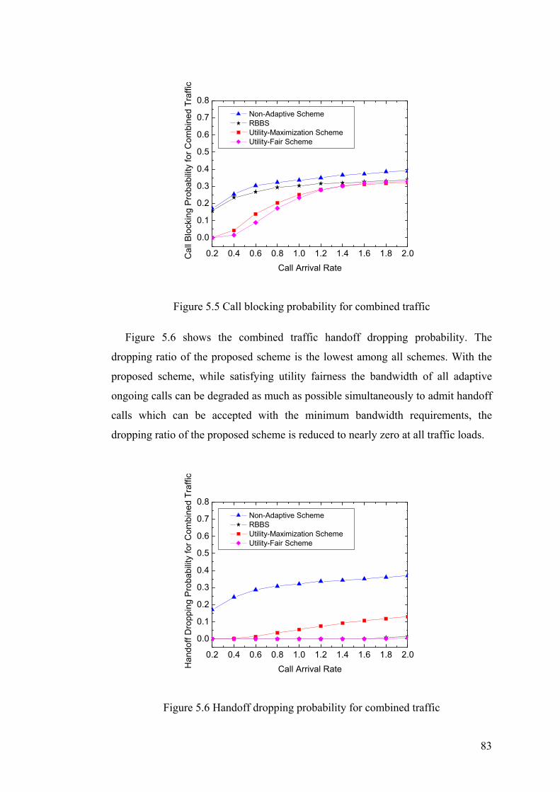
83
0.2 0.4 0.6 0.8 1.0 1.2 1.4 1.6 1.8 2.0
0.0
0.1
0.2
0.3
0.4
0.5
0.6
0.7
0.8 Non-Adaptive Scheme RBBS Utility-Maximization Scheme Utility-Fair Scheme
Cal
l Blo
ckin
g P
roba
bilit
y fo
r Com
bine
d Tr
affic
Call Arrival Rate
Figure 5.5 Call blocking probability for combined traffic
Figure 5.6 shows the combined traffic handoff dropping probability. The
dropping ratio of the proposed scheme is the lowest among all schemes. With the
proposed scheme, while satisfying utility fairness the bandwidth of all adaptive
ongoing calls can be degraded as much as possible simultaneously to admit handoff
calls which can be accepted with the minimum bandwidth requirements, the
dropping ratio of the proposed scheme is reduced to nearly zero at all traffic loads.
0.2 0.4 0.6 0.8 1.0 1.2 1.4 1.6 1.8 2.0
0.0
0.1
0.2
0.3
0.4
0.5
0.6
0.7
0.8 Non-Adaptive Scheme RBBS Utility-Maximization Scheme Utility-Fair Scheme
Han
doff
Dro
ppin
g P
roba
bilit
y fo
r Com
bine
d Tr
affic
Call Arrival Rate
Figure 5.6 Handoff dropping probability for combined traffic

84
Figure 5.7 illustrates the average call degradation ratio of the four schemes. It
can be seen that the degradation ratio of the proposed scheme is comparable to that
of RBBS and much higher than that of the non-adaptive scheme and utility-
maximization scheme. The fact that the proposed scheme features higher average
call degradation ratio than the utility-maximization scheme demonstrates the
tradeoffs between admitting calls (new and handoff) and call degradation.
Compared to the utility-maximization scheme the proposed scheme accommodates
more calls in the network due to its lower call blocking and handoff dropping
probabilities. Thus under the same network resource availability, on average each
call of the proposed scheme is degraded heavier than that of the utility-
maximization scheme.
0.2 0.4 0.6 0.8 1.0 1.2 1.4 1.6 1.8 2.0
0.0
0.1
0.2
0.3
0.4
0.5
0.6
0.7
0.8 Non-Adaptive Scheme RBBS Utility-Maximization Scheme Utility-Fair Scheme
Ave
rage
Cal
l Deg
rada
tion
Rat
io
Call Arrival Rate
Figure 5.7 Average call degradation ratio
Figure 5.8 shows the bandwidth utilization of the four schemes. The proposed
scheme exhibits better bandwidth utilization than the non-adaptive scheme and
RBBS. The bandwidth utilization of the proposed scheme is slightly lower than that
of the utility-maximization scheme and the trend becomes more evident when the
call arrival rate increases. When the call arrival rate reaches 2.0, the bandwidth used
by the proposed scheme comes close to equalling the bandwidth outside of the
reserved pool.

85
0.2 0.4 0.6 0.8 1.0 1.2 1.4 1.6 1.8 2.00.4
0.5
0.6
0.7
0.8
0.9
1.0
Non-Adaptive Scheme RBBS Utility-Maximization Scheme Utility-Fair Scheme
Ban
dwid
th U
tiliz
atio
n
Call Arrival Rate
Figure 5.8 Bandwidth utilization
5.8 Summary
This chapter presents a utility-fair bandwidth adaptation scheme for multimedia
wireless networks to solve the unfair utility allocation caused by the utility-
maximization scheme. The proposed scheme includes a core utility-fair bandwidth
allocation algorithm and its corresponding CAC and bandwidth reservation
mechanisms. The design details of the utility-fair algorithm are fully explained. The
key feature of the algorithm is that it quantizes the utility function of each call into
a linear piecewise function by dividing the utility range into a fixed number of
equal intervals. After quantization the approximate bandwidth allocation position of
each utility function can be located and then the exact bandwidth allocation can be
found using a straightforward equation. Simulation experiments have been
conducted to investigate the performance of the utility-fair bandwidth adaptation
scheme. Results show that the proposed scheme attains utility fairness while
keeping call blocking and handoff dropping probabilities substantially low.

86
Chapter 6 Utility-based Multi-Objective Bandwidth Adaptation
6.1 Introduction
In Chapter 4 a utility-maximization bandwidth adaptation scheme is proposed
for multimedia wireless networks from the network operators’ viewpoint and in
Chapter 5 a utility-fair bandwidth adaptation scheme is proposed from the end-
users’ viewpoint. Both schemes work in the fashion to meet one single utility-based
objective and the disadvantage of these two schemes is that they cannot satisfy the
QoS requirements of both network operators and end-users simultaneously. The
utility-maximization scheme increases the network utility but causes unfair utility
distribution among end-users. The utility-fair bandwidth adaptation scheme
achieves utility fairness but adversely affects the service qualities provided by
network operators. Thus a more sophisticated bandwidth adaptation scheme with
multiple objectives is desirable for wireless networks to balance the QoS
requirements of both network operators and end-users.
From the multimedia traffic model described in Chapter 4 it can be seen that the
simulated wireless network contains multiple groups of traffic belonging to
different classes, and all calls within the same traffic group have the same
bandwidth requirements and utility function. The utility fairness defined in Chapter
5 considers the utility function as individual to each call and it means that all
adaptive calls in each cell of the network, whatever the traffic group they belong to,
receive equal utilities. With the present of multiple groups of traffic, a more relaxed
fairness criterion, i.e. intra-group utility-fair, can be defined. Intra-group utility-fair
means that all calls within the same group receive equal utilities while calls
belonging to different traffic groups may have different utilities. In this chapter a
novel intra-group utility-fair and inter-group utility-maximization bandwidth
adaptation scheme is proposed which first guarantees that all calls belonging to the
same traffic group receive equal utilities and then maximizes the total utility of all
different groups of calls in each cell of the network. Instead of enabling utility-fair
bandwidth allocation among all calls in a uniform manner, the proposed scheme

87
applies utility-fair based on per traffic group to leverage the service qualities
degradation of network operators. The use of intra-group utility-fair also reduces
the number of utility functions to be considered for utility-maximization and allows
the exploration of optimal bandwidth allocation solution. To the author’s
knowledge, the work presented in this chapter is the first attempt to address the
problem of intra-group utility-fair and inter-group utility-maximization bandwidth
adaptation in wireless networks.
The chapter is organized as follows. Section 6.2 formulates the multi-objective
bandwidth adaptation problem. Section 6.3 describes the proposed intra-group
utility-fair and inter-group utility-maximization algorithm in details. Section 6.4
introduces the CAC and bandwidth reservation policies for the multi-objective
bandwidth adaptation scheme. Section 6.5 presents the simulation results of the
proposed scheme along with comparisons with previous mentioned bandwidth
adaptation schemes. Finally, Section 6.6 summarizes the chapter.
6.2 Problem Formulation
6.2.1 Bandwidth Degrades
Consider a saturated cell with m groups of adaptive traffic containing
1 2, , , mN N N… ongoing calls, when a new or handoff call arrives the allocated
bandwidth of ongoing calls can be degraded to smaller values to accommodate the
new or handoff call. Denote the utility function of the -thj group-i call as , ,( )i j i ju b
(1 ,1 )≤ ≤ ≤ ≤ ii m j N and its current allocated bandwidth as ,i jβ , thus the
degradable utility function of the -thj group-i call can be written as
, , , , ,( ) ( )i j i j i j i j i ju b u bβ↓ ↓ ↓= − min, , ,(0 )i j i j i jb bβ↓≤ ≤ − , where ,i jb↓ and min
,i jb are the
bandwidth degrades and the minimum bandwidth requirement of the call,
respectively. Assume the new or handoff call is an adaptive call belonging to
group-p (1 )p m≤ ≤ and denote its utility function as , 1 , 1( )p pp N p Nu b+ + . The
objective of bandwidth degrades is to find the bandwidth degrades profile ,{ }i jb↓ for
the m groups of ongoing calls and bandwidth allocation , 1pp Nb + for the new or

88
handoff call to maximize their total utility subject to intra-group utility-fair and
bandwidth constraints, i.e.
maximize , , , 1 , 11 1
( ) ( )i
p p
Nm
i j i j p N p Ni j
u b u b↓ ↓+ +
= =
+
∑∑ , (6.1)
subject to ( )1 1 2 2, , , , , 1 , 1
1 2
( ) ( ) ( ) if
1 ,1 , ,p pi j i j i j i j p N p N
i
u b u b u b i p
i m j j N
↓ ↓ ↓ ↓+ += = =
≤ ∀ ≤ ≤ ∀ ≤, (6.2)
min, , ,0 i j i j i jb bβ↓≤ ≤ − , (6.3)
, , , 11 1
( )i
p
Nm
i j i j p Ni j
b b Bβ ↓+
= =
− + ≤
∑∑ . (6.4)
where Equation (6.2) is the intra-group utility-fair constraint which guarantees that
all calls within the same group receive equal utilities and B is the total available
bandwidth for adaptive calls.
6.2.2 Bandwidth Upgrades
Assume that in an overloaded cell when a call is completed or handed off to
another cell, there are m groups of adaptive traffic containing 1 2, , , mN N N…
ongoing calls that have not received their maximum bandwidth requirements. The
released bandwidth from the completed or outgoing handoff call (denoted by β )
can be used to upgrade these ongoing calls to enhance their qualities and increase
network bandwidth utilization. Again, denote the utility function of the
-thj group-i call as , ,( )i j i ju b (1 ,1 )ii m j N≤ ≤ ≤ ≤ and its current allocated
bandwidth as ,i jβ , thus the upgradable utility function of the -thj group-i call can
be written as , , , , ,( ) ( )i j i j i j i j i ju b u bβ↑ ↑ ↑= + max, , ,(0 )β↑≤ ≤ −i j i j i jb b , where ,i jb↑ and max
,i jb
are the bandwidth upgrades and the maximum bandwidth requirement of the call,
respectively. The objective of bandwidth upgrades is to find the bandwidth
upgrades profile ,{ }i jb↑ for the m groups of ongoing calls to maximize their total
utility subject to intra-group utility-fair and bandwidth constraints, i.e.

89
maximize , ,1 1
( )iNm
i j i ji j
u b↑ ↑
= =∑∑ , (6.5)
subject to 1 1 2 2, , , , 1 2( ) ( ), 1 ,1 , ,i j i j i j i j iu b u b i m j j N↑ ↑= ≤ ∀ ≤ ≤ ∀ ≤ (6.6)
max, , ,0 i j i j i jb b β↑≤ ≤ − , (6.7)
,1 1
iNm
i ji j
b β↑
= =
≤∑∑ . (6.8)
where Equation (6.6) is the intra-group utility-fair constraint which guarantees that
all calls within the same group receive equal utilities.
6.3 The Proposed Utility-based Multi-Objective Algorithm
The essence of utility-based multi-objective bandwidth adaptation is to
maximize the total utility of m groups of utility functions, i.e. , ,1 1
( )iNm
i j i ji j
u b= =∑∑ ,
subject to intra-group utility-fair and bandwidth constraints. Because all calls within
the same traffic group are assigned the same utility function, denote the utility
function of each group-i call as ( )i iu b , and the problem of bandwidth adaptation
becomes to maximize 1
( )m
i i ii
u b N=
⋅∑ subject to intra-group utility-fair and bandwidth
constraints. According to Proposition 6.1, the intra-group utility-fair constraint can
be relaxed by aggregating the utility functions of all calls within the same traffic
group into one single group-based utility function. Thus bandwidth adaptation is
simplified to maximize the total utility of m group-based utility functions, i.e.
1( / )
m
i i i ii
u b N N=
⋅∑ , which only subject to bandwidth constraint.
Proposition 6.1 When the bandwidth allocation is intra-group utility-fair, for all
calls belonging to traffic group-i , the sum of their utility functions can be
substituted by the group-based utility function ( / )i i i iu b N N⋅ without changing their
total utility.

90
Proof: With intra-group utility-fair bandwidth allocation, for all group-i calls
their allocated bandwidth must be equal to each other since they have the same
utility function ( )i iu b . Assume that the total bandwidth allocation for group-i calls
is iB , thus the bandwidth allocated to each group-i call is /i iB N and the total
utility of all group-i calls is ( / )i i i iu B N N⋅ . For the group-based utility function
( / )i i i iu b N N⋅ , when it receives bandwidth allocation iB , its achieved utility is also
( / )i i i iu B N N⋅ .
To solve the utility-maximization bandwidth adaptation problem, all m group-
based utility functions are quantized into linear piecewise functions using equal
bandwidth interval b∆ , where /B b∆ is integer. After quantization utility function
( / )i i i iu b N N⋅ becomes 1 1 2 2( , , , , , , )i iK Ki i i i i ib u b u b u< > < > < >… , where iK is the
maximum <bandwidth, utility> level.
Proposition 6.2 For m linear piecewise utility functions
1 1 2 2( ), ( ), , ( )m mu b u b u b… , where 1 1 2 2( ) ( , , , , , , )= < > < > < >… i iK Ki i i i i i i iu b b u b u b u , a
necessary condition for their bandwidth allocation 1 2( , , , )mb b b… to be optimal is
that 1 21 ,i i m≤ ∀ ≤ ,
1 1
1i ib b= or 2
2 2
iKi ib b= or
1 1 2 2( ) ( )i i i iu b u b− +′ ′≥ and
1
1 1
iKi ib b= or
2 2
1i ib b= or
1 1 2 2( ) ( )i i i iu b u b+ −′ ′≤
where ( )i iu b−′ is the slope of the line segment on the immediate left side of
bandwidth allocation ib and ( )i iu b+′ is the slope of the line segment on the
immediate right side of bandwidth allocation ib in utility function ( )i iu b .
Proof: The result is a standard conclusion of the Kuhn-Tucker condition
[KUH50] [PER80]. If 1 1
1i ib b≠ , 2
2 2
iKi ib b≠ and
1 1 2 2( ) ( )i i i iu b u b− +′ ′< , then some bandwidth
can be subtracted from utility function 1 1( )i iu b and added to utility function
2 2( )i iu b
increasing the total utility. This contradicts the assumption that the bandwidth

91
allocation is optimal. Again, if 1
1 1
iKi ib b≠ ,
2 2
1i ib b≠ and
1 1 2 2( ) ( )i i i iu b u b+ −′ ′> , then some
bandwidth can be subtracted from utility function 2 2( )i iu b and added to utility
function 1 1( )i iu b increasing the total utility. This also contradicts the assumption
that the bandwidth allocation is optimal.
The proof can be illustrated using a simple example as shown in Figure 6.1.
Bandwidth Bandwidth
1(2 )u −′
1(2 )u +′
Utility Utility
2 (2 )u −′
2 (2 )u +′
1 2 3 1 2 3
1
1.5
3
1.5
2
3
00
1 2b =
2 2b =
1 1( )u b 2 2( )u b
Figure 6.1 Example illustration for the proof of Proposition 6.2
Two utility functions 1 1( ) ( 0, 0 , 1,1 , 2,1.5 , 3, 3 )u b = < > < > < > < > and
2 2( ) ( 0, 0 , 1,1.5 , 2, 2 , 3, 3 )u b = < > < > < > < > are considered in the example.
Assume that the total available bandwidth is 4; when 1 2b = and 2 2b = the total
utility U of the two utility functions reaches the maximum value and 3.5U = .
However, since 1 2( (2 ) 0.5) ( (2 ) 1)u u− +′ ′= < = bandwidth 1b∆ 1(0 1)b< ∆ ≤ can be
subtracted from utility function 1 1( )u b and added to utility function 2 2( )u b making
a new total utility newU , where 3.5 4newU< ≤ . This contradicts the assumption that
the bandwidth allocation is optimal. On the other hand, since
1 2( (2 ) 1.5) ( (2 ) 0.5)u u+ −′ ′= > = bandwidth 2b∆ 2(0 1)b< ∆ ≤ can be subtracted from
utility function 2 2( )u b and added to utility function 1 1( )u b making a new total
utility newU , where 3.5 4.5newU< ≤ . This also contradicts the assumption that the
bandwidth allocation is optimal.
92
Proposition 6.3 For the utility-maximization problem, the optimal bandwidth
allocation of each linear piecewise utility function exists on one of its discontinuity
<bandwidth, utility> points.
Proof: For utility function 1 1 2 2( ) ( , , , , , , )= < > < > < >… i iK Ki i i i i i i iu b b u b u b u , its
bandwidth allocation is either located on line segment ikil ( ik is integer and
1 1i ik K≤ ≤ − ) between two contiguous discontinuity <bandwidth, utility> points
,i ik ki ib u< > and 1 1,i ik k
i ib u+ +< > , or exactly on discontinuity <bandwidth, utility>
point ,i ik ki ib u< > . Assume that among the m linear piecewise utility functions
when the optimal maximum utility is achieved, the bandwidth allocation of 1m
1(1 )m m≤ ≤ utility functions is located on line segments and 2m 2 1( )m m m= −
utility functions is located exactly on discontinuity <bandwidth, utility> points; the
bandwidth allocation 11 2( , , , )mb b b… of the 1m utility functions is
1 2 111 2 11 2( ( 1) , ( 1) , , ( 1) )k k km
mml l l
k b b k b b k b b− ⋅∆ + − ⋅∆ + − ⋅∆ +… and the bandwidth
allocation 1 11 2( , , , )m m mb b b+ + … of the 2m utility functions are
1 11 2(( 1) , ( 1) , , ( 1) )m m mk b k b k b+ +− ⋅∆ − ⋅∆ − ⋅∆… , where ( 1)ik − denotes the number
of quantization interval b∆ that bandwidth allocation ib contains and kiil
b is the
bandwidth allocation on line segment ikil . One direct conclusion from Proposition
6.2 is that for the 1m utility functions whose bandwidth allocation is located on line
segments, 1 2 11 ,i i m≤ ∀ ≤ , 1 1 2 2( ) ( )i i i iu b u b′ ′= , where ( )i iu b′ is the slope of the line
segment that bandwidth allocation point ib is located on. Thus bandwidth
allocation 1 2 11 2 1
( , , , )k k kmm
l l lb b b… of the 1m utility functions can be collected and re-
allocated to exactly 1
/ ( 1)m
ii
B b k=
∆ − −
∑ line segments of them without changing
the total utility.
The proof can be illustrated using a simple example as show in Figure 6.2.

93
Bandwidth Bandwidth
1(2.5 )u −′1(2.5 )u +′
Utility Utility
2 (1.5 )u −′2 (1.5 )u +′
1 2 3 1 2 3
0.5
2
3
1.5
2.5
3
00
1 2.5b =2 1.5b =
1 1( )u b 2 2( )u b
2.5
2.5
1.5
2
Figure 6.2 Example illustration for the proof of Proposition 6.3
Two utility functions 1 1( ) ( 0, 0 , 1, 0.5 , 2, 2 , 3, 3 )u b = < > < > < > < > and
2 2( ) ( 0, 0 , 1,1.5 , 2, 2.5 , 3, 3 )u b = < > < > < > < > are considered in the example.
Assume that the total available bandwidth is 4. When 1 2.5b = and 2 1.5b = , the
total utility U of the two utility functions reaches the optimal maximum value and
4.5U = . Since 1 2( (2.5) (1.5) 1)u u′ ′= = , 0.5 bandwidth can be subtracted from utility
function 1 1( )u b and added to utility function 2 2( )u b making 1 2b = and 2 2b = ; and
the total utility of the two utility functions still keeps the optimal maximum value,
i.e. 4.5U = . Alternatively, 0.5 bandwidth can be subtracted from utility function
2 2( )u b and added to utility function 1 1( )u b making 1 3b = and 2 1b = ; and the total
utility of the two utility functions still keeps the optimal maximum value, i.e.
4.5U = .
Based on Proposition 6.3, the bandwidth adaptation is transformed to a multiple-
choice knapsack problem (MCKP) [SIN79] which aims to maximize the following
objective function, i.e.
maximize 1 1
iKml li i
i lx u
= =∑∑ (6.9)
subject to 1
1, 1, 2, ,iK
li
lx i m
=
= =∑ … , (6.10)

94
1 1
iKml li i
i lx b B
= =
≤∑∑ , (6.11)
{0,1}, 1, 2, , , 1, 2, ,li ix i m l K∈ = =… … .
where variable 1lix = when the -thi utility function is allocated bandwidth l
ib and
0lix = otherwise.
Finding optimal solution for the utility-maximization problem is NP-hard and
the utility-maximization algorithm proposed in Chapter 4 can be used to find the
near-optimal bandwidth allocation. In this chapter the problem is to maximize the
total utility of m group-based utility functions. Generally there are only a limited
number of adaptive traffic groups in wireless networks making the size of the
problem very small. Thus it is possible to explore the optimal bandwidth allocation
algorithm.
Branch-and-bound is a popular approach for solving combinatorial optimization
problems by the intelligent complete enumeration of the solution space in the
search tree [KEL04] [KHA98]. In this section, an efficient branch-and-bound
optimal bandwidth allocation algorithm is proposed to perform exhaustive search in
the discrete <bandwidth, utility> points of the m utility functions without
generating all the nodes. Before presenting the branch-and-bound algorithm, some
definitions are introduced.
Definition 6.1 Upper bound is a bound which the optimal value of the objective
function (1 1
iKml li i
i lx u
= =∑∑ in this case) can never exceed. The upper bound can be
computed by relaxing the integrality constraint on lix of the objective function.
Definition 6.2 Lower bound is a bound which the optimal value of the
objective function can always equal or exceed. The lower bound can be calculated
using the Greedy method as stated in [KEL04].
Definition 6.3 Live node is a node that has been generated in the tree but whose
children have not been generated yet.
95
Definition 6.4 E-node is the live node with the currently largest upper bound. In
other words, an E-node is a node currently being expanded.
Definition 6.5 Branching utility function is the utility function which is going
to be fixed (allocated bandwidth) when expanding the E-node. The calculation of
branching utility function will be introduced later.
The optimal bandwidth allocation is found by the iterative generation of a tree.
A node in the tree represents a bandwidth allocation state { }lix (1 ,1 )ii m l K≤ ≤ ≤ ≤
where there may be some variables which are known (values are assigned), and
some others which are unknown (values are not assigned). At any bandwidth
allocation state, a utility function ( )i iu b is either free with all its variables
1 2( , , , )iKi i ix x x… unknown denoting no bandwidth has been allocated to it or fixed
with all its variables known denoting some bandwidth has been allocated to it. For a
fixed utility function ( )i iu b , 1lix = means it has been allocated bandwidth l
ib and
0lix = otherwise. Children nodes are generated from their parent node by
expanding it based on the unknown variables. For example, expanding a node based
on the unknown variable lix of free utility function ( )i iu b generates a child node
with 1lix = . The basic procedure of the branch-and-bound algorithm is summarized
as follows:
1. Start with a solution state where all utility functions are free, i.e. all
variables are unknown. Select the branching utility function after computing
the upper bound, and then initialize the search tree with this node as the only
live node.
2. Find the E-node, i.e. the live node with the largest upper bound among all
live nodes.
3. If the E-node does not have any free utility function, i.e. all utility functions
are fixed, then this node represents the optimal bandwidth allocation
solution and the algorithm terminates.

96
4. If the E-node has at least one free utility function, then expand the E-node
by fixing its branching utility function.
5. Go back to Step 2.
During the search phase of the branch-and-bound algorithm, Proposition 6.2 can
be applied to prune the tree by exploiting the structure of linear piecewise utility
functions. The pseudo-code of the branch-and-bound algorithm is described as
follows and the notations of the algorithm can be found in Table 6.1.
Table 6.1 Notations used in the branch-and-bound algorithm
B the total available bandwidth to be allocated availb the current available bandwidth to be allocated
iu the quantized group-based utility function of group-i calls (1 )i m≤ ≤
iK the maximum <bandwidth, utility> level of utility function iu m the total number of utility functions (traffic groups)
freem the number of free utility functions (the utility functions that have not received bandwidth allocation)
n the numerical ID of the branching utility function b the bandwidth requirements vector, i.e. 11 1
1 1(( , , ), , ( , , ))mKKm mb b b b… … … ,
where lib (1 )il K≤ ≤ is the bandwidth requirement of the -thl
<bandwidth, utility> point of utility function iu x the bandwidth allocation vector, i.e. 11 1
1 1(( , , ), , ( , , ))mKKm mx x x x… … … ,
where 0 1≤ ≤lix . For a fixed utility function iu , 1l
ix = means the utility function has been allocated bandwidth l
ib and 0lix = otherwise; while
for a free utility function iu , lix may be fractional because of the
calculation of upper bound u the achievable utility vector, i.e. 11 1
1 1(( , , ), , ( , , ))mKKm mu u u u… … … , where
liu is the achievable utility by allocating bandwidth to the -thl
<bandwidth, utility> point of utility function iu v the achieved utility vector, i.e. 1( , , )mv v… , where iv is the achieved
utility of utility function iu s the utility function status vector, i.e. 1( , , )ms s… , where {0,1}is ∈ . It
indicates the fixed or free status of the utility functions in the current bandwidth allocation solution; 1is = means utility function iu has received bandwidth allocation and 0is = otherwise
upperU the upper bound of the objective function as in Definition 6.1 lowerU the lower bound of the objective function as in Definition 6.2 objU the achieved utility value of the objective function

97
Branch-and-bound algorithm:
(1) // initialization , , 0, 0, 0free avail objm m b B U s x= = = = =
// calculate the upper bound as in Definition 6.1 ( , , , , , )upper free availU calculateUB m b b u s x= // calculate the lower bound as in Definition 6.2 ( , , , , , )lower free availU calculateLB m b b u s x= // find the numerical ID of the branching utility function find n when 1, ,[ ][ ] 1
nl Kx n l = =… , upperU is achieved // insert the root node into the tree
( , , , , , , , )free avail upper lower objinsertNode m b U U U n s x (2) while (true) // find the E-node as in Definition 6.4 ( )node findENode= . , .x node x n node n= =
if ( . 0)freenode m = // return the bandwidth allocation vector x return .node x // fix the branching utility function 1, ,. 1, [ ] 1, [ ][ ] 0
n
free freel Km node m s n x n l == − = =…
// no need to branch if the conditions from Proposition 6.2 cannot be met if ( 1 21 , ,≤ ∀ ≤i i m (
1 1
1i ib b= or 2
2 2
iKi ib b= or
1 1 2 2( ) ( )i i i iu b u b− +′ ′≥ ) and
( 1
1 1
iKi ib b= or
2 2
1i ib b= or
1 1 2 2( ) ( )i i i iu b u b+ −′ ′≤ ))
for 1 to nl K= // allocate bandwidth to the -thl <bandwidth, utility> point of utility // function ( )n nu b .avail availb node b= if (( [ ][ ]) 0)availb b n l− ≥ [ ][ ], . [ ][ ], , [ ][ ] 1avail avail obj objb b b n l U nodeU u n l x x x n l′ ′= − = + = = ( , , , , , , , )upper free avail objU calculateUB m b b u U v s x′= max{ , ( , , , , , , , )}lower lower free avail objU U calculateLB m b b u U v s x′= // no need to branch if upper bound is not more than lower bound if ( )upper lowerU U>
find n when 1, ,[ ][ ] 1nl Kx n l =′ =… , upperU is achieved
( , , , , , , , )free avail upper lower objinsertNode m b U U U n s x′
The algorithm starts the tree search by creating the root node with all utility
functions free. Because initially root node is the only live node, it becomes the E-
node. Then the algorithm fixes the E-node and expands it based on the variables of
the branching utility function n , where n is found by relaxing the integrality

98
constraint on the variables and calculating the upper bound of the objective
function. The algorithm keeps expanding live nodes until the optimal solution is
found. At a given node in the tree if the optimal solution cannot occur in any of its
descendent nodes, there is no need to branch this node. Hence, before branching the
E-node, Proposition 6.2 is used to check if the optimal solution may exist in its
descendent nodes. If the optimal bandwidth allocation conditions cannot be
satisfied, the algorithm stops branching the current node and looks for another E-
node; in this way the tree is pruned. Similarly, if the upper bound of the E-node is
not larger than the lower bound, all its descendent nodes can also be pruned. If the
branching E-node has no free utility functions the algorithm terminates and the
current solution vector x yields the optimal solution. Otherwise, the algorithm
fixes the branching utility function ( )n nu b . For each <bandwidth, utility> point l of
utility function ( )n nu b , the algorithm does the following: extend x by allocating
bandwidth lnb to <bandwidth, utility> point l to generate a new partial solution x′ .
If allocating bandwidth lnb to <bandwidth, utility> point l is feasible, the algorithm
fixes the branching utility function n and inserts a new node with solution x′ into
the search tree. The procedure of the algorithm is shown in Figure 6.3.
12x 2
2x 32x
13x 3
3x 11x 2
1x11x
23x1
3x
A
C DB
J E F H I
K L
F G
23x
1
2 34
5
Figure 6.3 Branch-and-bound algorithm illustration

99
It is assumed that the objective is to maximize the total utility of three linear
piecewise utility functions 1 1( )u b , 2 2( ) u b and 3 3( )u b each of which has three
<bandwidth, utility> points, i.e. 3 3
1 1
l li i
i lx u
= =∑∑ , subject to bandwidth constraint. The
algorithm starts by creating root node A with all three utility functions free. Since
node A is the only live node it becomes the E-node. Suppose that after computing
the upper bound of the objective function it is found that the numerical ID of the
branching utility function is 2. The algorithm then expands node A by fixing the
branching utility function 2 2( )u b . This generates three more live nodes B, C and D.
Suppose now node C has the largest upper bound among all live nodes thus it
becomes the E-node and also suppose the numerical ID of the branching utility
function on node C is 3. Expansion of node C by fixing the branching utility
function 3 3( )u b generates nodes E, F, and G. Suppose now node D is the E-node
and the numerical ID of the branching utility function on node D is 1. Node D is
then expanded by fixing the branching utility function 1 1( )u b . It can be noticed that
the expansion of node D only generates two nodes H and I. This is because
generating the node based on variable 31x violates the bandwidth constraint.
Suppose after this expansion node B has the highest upper bound among the live
nodes and the numerical ID of the branching utility function is 1. Thus it is
expanded by fixing the branching utility function 1 1( )u b . Expansion continues in
this fashion until node L becomes the E-node. Since at node L there are no more
free utility functions, the algorithm terminates and node L represents the optimal
bandwidth allocation solution. In the figure, the sequence at which the nodes are
expanded is given beside the left of the nodes. The label jix written beside a branch
indicates 1jix = which means utility function ( )i iu b is allocated a bandwidth of j
ib .
6.4 CAC and Bandwidth Reservation
Apart from the multi-objective bandwidth adaptation algorithm, CAC and
bandwidth reservation policies are used to reduce the call blocking and handoff
dropping probabilities.

100
During the process of bandwidth adaptation the multi-objective scheme needs to
maintain the intra-group utility fairness among calls belonging to the same traffic
group. The CAC and bandwidth reservation mechanisms of the multi-objective
scheme are identical to those of the utility-fair bandwidth adaptation scheme
proposed in Chapter 5 after replacing the utility-fair bandwidth requirement with
intra-group utility-fair bandwidth requirement. With the multi-objective bandwidth
adaptation scheme, the intra-group utility-fair bandwidth requirement of the new or
handoff call is also dependent on its adaptive characteristics. If the new or handoff
call belongs to hard real-time traffic, its intra-group utility-fair bandwidth
requirement refers to the maximum bandwidth requirement of the call; if the new or
handoff call belongs to adaptive real-time or non-real-time traffic, its intra-group
utility-fair bandwidth requirement refers to the bandwidth requirement that enables
the call to achieve the same utility as other ongoing calls belonging to its traffic
group. The pseudo-code for handling call arrivals and departures can be referred to
that of the utility-fair bandwidth adaptation scheme and it will not be described
repetitively here.
6.5 Simulation Results
Simulation experiments have been conducted to highlight the performance of the
proposed multi-objective bandwidth adaptation scheme by comparing it with four
other bandwidth adaptation schemes introduced in the previous chapters, i.e. the
non-adaptive scheme, RBBS, utility-maximization scheme and utility-fair scheme.
In the experiments, in order to provide quantitative measurement to evaluate the
intra-group utility fairness, a new application-level performance metric called
average intra-group utility fairness deviation is introduced. Intra-group utility
fairness deviation is defined as the standard deviation of the actual received utility
of each ongoing call from its expected intra-group fair utility under the current load
situation of the cell, i.e.
fair 2, ,
1
1= ( )1
iN
i i j i jji
d u uN =
−− ∑ (6.12)

101
where ,i ju and fair,i ju are the actual received utility and the expected intra-group fair
utility of the -thj group-i call, respectively. From the definition it is known that
the higher the intra-group utility fairness deviation is, the more unfairly the utility is
distributed among calls within the same traffic group. Based on intra-group utility
fairness deviation, average intra-group utility fairness deviation is defined as
1
/m
ii
d d m=
= ∑ (6.13)
where m is the number of adaptive traffic groups.
Figure 6.4 demonstrates the average intra-group utility fairness deviation of the
five schemes. From the figure it can be seen that RBBS has the highest average
intra-group fairness deviation and then the utility-maximization scheme. The intra-
group utility fairness deviation of the non-adaptive scheme, utility-fair scheme and
proposed scheme are all zero since with these three schemes for each ongoing call
its actual received utility equals to its expected intra-group fair utility, i.e.
, ,fair
i j i ju u= (for the non-adaptive scheme max, , ,
fairi j i j i ju u u= = ).
0.2 0.4 0.6 0.8 1.0 1.2 1.4 1.6 1.8 2.0
0.0
0.1
0.2
0.3
0.4
0.5
0.6
0.7
0.8
Non-Adaptive Scheme RBBS Utility-Maximization Scheme Utility-Fair Scheme Multi-Objective Scheme
Ave
rage
Intra
-Gro
up U
tility
Fai
rnes
s D
evia
tion
Call Arrival Rate
Figure 6.4 Average intra-group utility fairness deviation
After comparing the average intra-group fairness deviation, Figure 6.5 shows the
utility fairness deviation for all traffic groups of the five schemes. Again, RBBS has

102
the worst performance among all schemes. Since the proposed scheme only aims to
satisfy the intra-group utility fairness, its utility fairness deviation is higher than
that of the non-adaptive scheme and utility-fair scheme. The results reveal that with
the proposed scheme utilities are not allocated equally among calls belonging to
different groups. But the utility fairness deviation of the proposed scheme is
relatively low compared to that of RBBS and it is not more than 0.13 for all call
arrival rates.
0.2 0.4 0.6 0.8 1.0 1.2 1.4 1.6 1.8 2.0
0.0
0.1
0.2
0.3
0.4
0.5
0.6
0.7
0.8
Non-Adaptive Scheme RBBS Utility-Maximization Scheme Utility-Fair Scheme Multi-Objective Scheme
Util
ity F
airn
ess
Dev
iatio
n
Call Arrival Rate
Figure 6.5 Utility fairness deviation
Figure 6.6 depicts the average cell utility of the five schemes. It can be observed
that the average cell utility of the proposed scheme is nearly identical to that of the
utility-fair scheme. The results show that by maximizing the total utility of different
groups of traffic after obtaining intra-group utility fairness the proposed scheme
have produced attractive network utility.

103
0.2 0.4 0.6 0.8 1.0 1.2 1.4 1.6 1.8 2.00
102030405060708090
100110120
Non-Adaptive Scheme RBBS Utility-Maximization Scheme Utility-Fair Scheme Multi-Objective Scheme
Ave
rage
Cel
l Util
ity
Call Arrival Rate
Figure 6.6 Average cell utility
Figure 6.7 illustrates the combined traffic call blocking probability comparison
of the five schemes. The proposed scheme achieves good performance when the
call arrival rate is low. Although the blocking ratio of the proposed scheme
becomes slightly higher than that of the other three adaptive schemes at heavy
traffic load (at the call arrival rates from 1.4 to 2.0), it is kept on an acceptable
level.
0.2 0.4 0.6 0.8 1.0 1.2 1.4 1.6 1.8 2.0
0.0
0.1
0.2
0.3
0.4
0.5
0.6
0.7
0.8
Non-Adaptive Scheme RBBS Utility-Maximization Scheme Utility-Fair Scheme Multi-Objective Scheme
Cal
l Blo
ckin
g P
roba
bilit
y fo
r Com
bine
d Tr
affic
Call Arrival Rate
Figure 6.7 Call blocking probability for combined traffic

104
Figure 6.8 depicts the combined traffic handoff dropping probability. When the
call arrival rate is low (not more than 1.0), the dropping ratio of the proposed
scheme is close to zero. The dropping of handoff calls starts to be seen when the
call arrival rate becomes higher than 1.0 and it keeps increasing with the call arrival
rate. At the call arrival rate of 2.0, it is about 20% lower than that of the non-
adaptive scheme and 4% higher than that of the utility-maximization scheme.
0.2 0.4 0.6 0.8 1.0 1.2 1.4 1.6 1.8 2.0
0.0
0.1
0.2
0.3
0.4
0.5
0.6
0.7
0.8
Non-Adaptive Scheme RBBS Utility-Maximization Scheme Utility-Fair Scheme Multi-Objective Scheme
Han
doff
Dro
ppin
g P
roba
bilit
y fo
r Com
bine
d Tr
affic
Call Arrival Rate
Figure 6.8 Handoff dropping probability for combined traffic
Figures 6.9 and 6.10 illustrate the handoff dropping probabilities for Class I and
Class II traffic, respectively. For Class I handoff calls the handoff dropping
probability of the proposed scheme is only slightly higher than that of RBBS and
the utility-fair scheme. In terms of Class II handoff calls dropping probability, the
proposed scheme performs better than the non-adaptive scheme and worse than the
other three schemes. Since Class II calls does not have minimum bandwidth
requirements, the dropping of Class II handoff calls is mainly caused by
maintaining the intra-group utility fairness and maximizing the total utility of
different groups of calls.

105
0.2 0.4 0.6 0.8 1.0 1.2 1.4 1.6 1.8 2.0
0.0
0.1
0.2
0.3
0.4
0.5
0.6
0.7
0.8
Non-Adaptive Scheme RBBS Utility-Maximization Scheme Utility-Fair Scheme Multi-Objective Scheme
Han
doff
Dro
ppin
g P
roba
bilit
y fo
r Tra
ffic
Cla
ss I
Call Arrival Rate
Figure 6.9 Handoff dropping probability for traffic class I
0.2 0.4 0.6 0.8 1.0 1.2 1.4 1.6 1.8 2.0
0.0
0.1
0.2
0.3
0.4
0.5
0.6
0.7
0.8
Non-Adaptive Scheme RBBS Utility-Maximization Scheme Utility-Fair Scheme Multi-Objective Scheme
Han
doff
Dro
ppin
g P
roba
bilit
y fo
r Tra
ffic
Cla
ss II
Call Arrival Rate
Figure 6.10 Handoff dropping probability for traffic class II
Figure 6.11 shows the average call degradation ratio of all schemes. The
proposed scheme experiences higher degradation ratio than the non-adaptive
scheme and utility-maximization scheme, and lower degradation ratio than RBBS
and the utility-fair scheme. The results indicate that the proposed scheme achieves
high average cell utility and low call blocking and handoff dropping probabilities
without enforcing heavy call degradation as tradeoffs.

106
0.2 0.4 0.6 0.8 1.0 1.2 1.4 1.6 1.8 2.0
0.0
0.1
0.2
0.3
0.4
0.5
0.6
0.7
0.8
Non-Adaptive Scheme RBBS Utility-Maximization Scheme Utility-Fair Scheme Multi-Objective Scheme
Ave
rage
Cal
l Deg
rada
tion
Rat
io
Call Arrival Rate
Figure 6.11 Average call degradation ratio
Figure 6.12 compares the bandwidth utilization of the five schemes. When the
call arrival rate is low (not more than 1.0), the bandwidth utilization of the proposed
scheme is close to that of the utility-fair scheme. When the call arrival rate reaches
1.0, the bandwidth utilization of the proposed scheme starts becoming higher than
that of the utility-fair scheme and the advantage increases as the call arrival rate
increases. At the call arrival rate of 2.0, the bandwidth utilization of the proposed
scheme is only slightly lower than that of the utility-maximization scheme.
0.2 0.4 0.6 0.8 1.0 1.2 1.4 1.6 1.8 2.00.4
0.5
0.6
0.7
0.8
0.9
1.0
Non-Adaptive Scheme RBBS Utility-Maximization Scheme Utility-Fair Scheme Multi-Objective Scheme
Ban
dwid
th U
tiliz
atio
n
Call Arrival Rate
Figure 6.12 Bandwidth utilization

107
6.6 Summary
In this chapter, an intra-group utility-fair inter-group utility-maximization
bandwidth adaptation scheme is proposed. The scheme is performed to meet two
objectives in the preference order: 1) all calls belonging to the same traffic group
receive fair utilities; and 2) the total utility of all different groups of calls in each
individual cell of the network is maximized. By aggregating the utility functions of
all calls within the same group into the group-based utility function, the multi-
objective bandwidth adaptation can be simplified to a lightweight utility-
maximization problem. A branch-and-bound algorithm is then presented to obtain
the optimal bandwidth allocation and a proposition derived from Kuhn-Tucker
condition is applied to reduce the search space of the algorithm. The CAC and
bandwidth reservation mechanisms have also been incorporated into the bandwidth
adaptation scheme to reduce the call blocking and handoff dropping probabilities.
Extensive simulation experiments have been carried out to evaluate the
performance of the multi-objective bandwidth adaptation scheme. Numerical results
show that the proposed scheme achieves excellent intra-group utility fairness and
network utility while maintaining competitive connection-level QoS.

108
Chapter 7 Conclusions and Future Work
7.1 Conclusions
QoS provisioning in wireless networks is a challenging problem due to the
limited and variable wireless link bandwidth. The goal of this research is to explore
efficient bandwidth adaptation schemes to provide QoS support for multimedia
traffic with different bandwidth requirements in wireless networks.
Chapter 3 introduces the fundamental issues of utility-based bandwidth
adaptation in multimedia wireless networks. Multimedia traffic is classified into
different classes according to their adaptive characteristics and a utility function
with appropriate shape is defined for each class of traffic to model its applications.
Based on application utility functions, the utility-based adaptive traffic model is
then presented for multimedia traffic. The objectives of utility-based bandwidth
adaptation are discussed and the procedure of bandwidth adaptation is divided into
two processes – bandwidth degrades and bandwidth upgrades. The work presented
in this chapter serves as the foundation for the utility-based bandwidth adaptation
schemes which will be proposed in the later chapters.
With the availability of utility-based adaptive traffic model, Chapter 4 presents a
utility-maximization bandwidth adaptation scheme for multimedia wireless
networks. A mathematical formulation of the utility-maximization bandwidth
adaptation problem is presented and a search tree based algorithm is described to
maximize the total utility of all calls in the network. CAC and bandwidth
reservation have also been integrated into the scheme to reduce the call blocking
and handoff dropping probabilities. After presenting and validating the multimedia
wireless network simulation model, extensive experiments have been carried out to
evaluate the performance of the proposed utility-maximization scheme. Simulation
results show that the scheme is effective in increasing network utility while keeping
call blocking and handoff dropping probabilities low.
The drawback of the utility-maximization scheme is that it ignores the QoS
requirements of end-users and causes the utilities to be distributed unfairly among

109
ongoing calls in the network. To solve such problem, Chapter 5 presents a utility-
fair bandwidth adaptation scheme for multimedia wireless networks. The scheme
includes a utility-fair bandwidth adaptation algorithm to enable all adaptive calls in
each cell of the network to receive fair utilities, and CAC and bandwidth
reservation polices to provide QoS guarantees to the new and handoff calls. The
quantization of utility function by dividing its utility range into a fixed number of
equal intervals is the key feature of the utility-fair algorithm. The simulation results
demonstrate that the proposed utility-fair scheme attains utility fairness and reduces
call blocking and handoff dropping probabilities.
Chapter 6 proposes a multi-objective bandwidth adaptation scheme to meet the
QoS requirements of both network operators and end-users. The scheme allocates
bandwidth to calls based on per traffic group. It first guarantees that all calls within
the same group receive fair utilities, and then maximizes the total utility of all
different groups of calls. By aggregating utility functions of all calls within the
same group into their group-based utility function, the bandwidth adaptation is
simplified to a lightweight utility-maximization problem. A branch-and-bound
algorithm is then presented to obtain the optimal bandwidth allocation solution.
Moreover, a proposition derived from Kuhn-Tucker condition is applied to improve
the efficiency of the branch-and-bound algorithm. Similar to the previous proposed
schemes, the multi-objective scheme also includes CAC and bandwidth reservation
mechanisms for the new and handoff calls QoS support. The simulation results have
shown the effectiveness of the multi-objective scheme.
7.2 Future Work
The research work in this thesis focuses on utility-based bandwidth adaptation
for multimedia traffic in wireless networks. Even though the simulation results have
clearly demonstrated the superior performance of the proposed bandwidth
adaptation schemes, there still remain some open issues to be investigated in the
future as an extension of this research.
• More Application-Level QoS Measurements

110
To evaluate the application-level QoS in multimedia wireless networks, the
work presented in this thesis only uses one measurement, i.e. the application
utility. While other measurements such as delay/delay variation and loss/error
rate can also reflect the application-level QoS and it is desirable for future
bandwidth adaptation schemes to consider these QoS measurements.
• Traffic Prioritization
This thesis assumes that all calls in the network have the same priority level.
Such assumption has ignored the fact that some customers are willing to pay
more for better services and such customers may get annoyed by the QoS
degradation during network congestion. In the future calls could be specified
with multiple priority levels to reflect the importance of a wide range of
customers. Bandwidth adaptation could then differentiate calls according to
their priority levels to provide better QoS to high-value customers. For example,
during bandwidth degrades calls with lower priority levels can be degraded first
and during bandwidth upgrades calls with higher priority levels can be upgraded
first.
• Adaptive Bandwidth Reservation
Adaptive bandwidth reservation is also a promising research direction. The
bandwidth reservation deployed in this thesis is fairly simple since it only
reserves a fixed percentage of bandwidth in each cell for handoff calls.
Although fixed bandwidth reservation has reduced handoff dropping probability
there is still space for improvement. A more elaborate bandwidth reservation
mechanism with low computational and message overhead is worth
investigating to dynamically adjust the amount of reserved bandwidth according
to the predicted handoff traffic load.
• Utility Fluctuations and Message Overhead Evaluation
The proposed bandwidth adaptation schemes achieve attractive performance
in both connection-level and application-level QoS. However, all these do not
come without a price. Bandwidth adaptation subjects ongoing calls to frequent
utility fluctuations which may annoy end-users. Moreover, bandwidth

111
adaptation involves extra network message overhead since BS needs to send
messages to inform the senders and receivers of the new allocated bandwidth of
the applications. Message overhead is proportional to the number of
applications whose bandwidth is re-allocated and it is inherently high for the
utility-fair bandwidth adaptation scheme because every time bandwidth
adaptation happens the allocated bandwidth of all adaptive calls needs to be
changed to maintain the utility fairness criterion. Utility fluctuations and
message overhead are serious problems introduced by bandwidth adaptation and
the evaluation of their negative effect requires more research in the future.
• Physical Layer Adaptation
This thesis only deals with bandwidth adaptation in the application layer of
multimedia wireless networks. Bandwidth adaptation is assumed to be
continuous, i.e. the multimedia application can be adapted to any bit rate
between its minimum and maximum bandwidth requirements. However, such
an assumption is rather ideal for the network architecture with multiple OSI
layers. Although some technologies have been developed for the continuous
multimedia adaptation in the application layer, there is still lack of research for
other OSI layers adaptation especially physical layer adaptation. Due to the fact
that most wireless networks technologies such as FDMA and TDMA allocate
resource based on channels in the physical layer, special implementation
approaches need to be investigated to support continuous multimedia adaptation
and this leads to another interesting yet challenging topic for future research.

112
Appendix A Author’s Publications
Journal Papers
[LU07] N. Lu and J. Bigham, “On Utility-Fair Bandwidth Adaptation for Multi-Class Traffic QoS Provisioning in Wireless Networks,” Computer Networks, vol. 51, no. 10, pp. 2554-2564, July 2007.
[LU06] N. Lu and J. Bigham, “An Integrated Bandwidth Adaptation Scheme for Multimedia Wireless Networks and its Connection-Level Performance Analysis,” Journal of Communications Software and Systems (JCOMSS), Special Issue on QoS in Wireless Networks, vol. 2, no. 2, June 2006 (Electronic Publication).
[BIG04] J. Bigham, L. Cuthbert, X. Yang, N. Lu and D. Ryan, “Using Intelligent Agents for Managing Resources in Military Communications,” Computer Networks, vol. 46, no. 5, pp. 709-721, Dec. 2004.
Conference Papers
[LU06-1] N. Lu, J. Bigham and N. Nasser, “An Intra-Class and Inter-Class Utility-Fair Bandwidth Adaptation Algorithm for Multi-Class Traffic in Wireless Networks,” Proceedings of the 12th Asia-Pacific Conference on Communications (APCC ’06), Aug. 2006.
[NSA06] N. Nasser, N. Lu and J. Bigham, “Performance Analysis of a Threshold-based Call Admission Control Scheme for Multimedia Wireless Networks,” Proceedings of the 12th Asia-Pacific Conference on Communications (APCC ’06), Aug. 2006.
[LU06-2] N. Lu and J. Bigham, “An Optimal Bandwidth Adaptation Algorithm for Multi-Class Traffic in Wireless Networks,” Proceedings of the 3rd International Conference on Quality of Service in Heterogeneous Wired/Wireless Networks (QShine ’06), Aug. 2006.
[LU06-3] N. Lu and J. Bigham, “Efficient Utility-based Bandwidth Adaptation for Multimedia Wireless Networks,” Proceedings of the Joint International Conferences on Optical Internet and Next Generation Network (COIN-NGNCON ’06), July 2006.
[LU06-4] N. Lu and J. Bigham, “On Utility-Fair Bandwidth Adaptation for Multimedia Wireless Networks,” Proceedings of the 4th International Conference on Communications, Circuits and Systems (ICCCAS ’06), June 2006.

113
[LU06-5] N. Lu and J. Bigham, “Intra-Class Utility-Fair Bandwidth Adaptation for Multi-Class Traffic in Wireless Networks,” Proceedings of the 1st International Workshop on Future Mobile and Ubiquitous Information Technologies (FMUIT ’06), May 2006.
[LU05-1] N. Lu and J. Bigham, “Utility-Maximization Bandwidth Adaptation for Multi-Class Traffic QoS Provisioning in Wireless Networks,” Proceedings of the 1st ACM International Workshop on Quality of Service & Security in Wireless and Mobile Networks (Q2SWinet ’05), pp. 136-143, Oct. 2005.
[LU05-2] N. Lu and J. Bigham, “Utility-based Adaptive Bandwidth Allocation for Multi-Class Traffic in Wireless Networks,” Proceedings of the 19th International Teletraffic Congress (ITC ’19), pp. 879-888, Aug. 2005.
[BIG03] J. Bigham, D. Gamez, and N. Lu, “Safeguarding SCADA Systems with Anomaly Detection,” Proceedings of the 2nd International Workshop on Mathematical Methods, Models and Architectures for Computer Network Security (MMM-ACNS ’03), pp. 171-182, Sept. 2003.

114
References
[ACA94] A.S. Acampora and M. Naghshineh, “Control and Quality-of-Service Provisioning in High-Speed Microcellular Networks,” IEEE Personal Communications, vol. 1, no. 2, pp. 36-43, 2nd Quarter, 1994.
[AHN03] K.-M. Ahn and S. Kim, “Optimal Bandwidth Allocation for Bandwidth Adaptation in Wireless Multimedia Networks,” Computers and Operations Research, vol. 30, no. 13, pp. 1917-1929, Nov. 2003.
[ALJ00] A. Aljadhai and T.F. Znati, “A Bandwidth Adaptation Scheme to Support QoS Requirements of Mobile Users in Wireless Environments,” Proceedings of the 9th International Conference on Computer Communications and Networks, pp. 34-39, Oct. 2000.
[ALP03] T. Alpcan and T. Basar, “A Utility-Based Congestion Control Scheme for Internet-Style Networks with Delay,” Proceedings of the 22nd Annual Joint Conference of the IEEE Computer and Communications Societies (INFOCOM ’03), vol. 3, pp. 2039-2048, March 2003.
[ALW96] A. Alwan, R. Bagrodia, N. Bambos, M. Gerla, L. Kleinrock, J. Short, and J. Villasenor, “Adaptive Mobile Multimedia Networks,” IEEE Personal Communications, vol. 3, no. 2, pp. 34-51, April 1996.
[BAN05] N. Banerjee, K. Basu, and S.K. Das, “Adaptive Resource Management for Multimedia Applications in Wireless Networks,” Proceedings of the 6th IEEE International Symposium on a World of Wireless Mobile and Multimedia Networks (WoWMoM ’05), pp. 250-257, June 2005.
[BER92] D. Bertsekas and R. Gallager. Data Networks. Prentice Hall, 1992.
[BHA98] V. Bharghavan, K.-W. Lee, S. Lu, S. Ha, J.-R. Li, and D. Dwyer, “The Timely Adaptive Resource Management Architecture,” IEEE Personal Communications, vol. 5, no. 4, pp. 20-31, Aug. 1998.
[BIA98] G. Bianchi, A.T. Campbell, and R.R.-F. Liao, “On Utility-Fair Adaptive Services in Wireless Networks,” Proceedings of the 6th International Workshop on Quality of Service (IWQOS ’98), pp. 256-267, May 1998.
[BIS97] S.K. Biswas and B. Sengupta, “Call Admissibility for Multirate Traffic in Wireless ATM Networks,” Proceedings of 16th Annual Joint Conference of the IEEE Computer and Communications Societies (INFOCOM ’97), vol. 2, pp. 649-657, April 1997.

115
[BOC99] P. Bocheck, Y. Nakajima, and S.-F. Chang, “Real-Time Estimation of Subjective Utility Functions for MPEG-4 Video Objects,” Proceedings of the 9th International Packet Video Workshop (PacketVideo ’99), April 1999.
[BRE98] L. Breslau and S. Shenker, “Best-Effort Versus Reservations: A Simple Comparative Analysis,” Proceedings of the ACM SIGCOMM ’98 Conference on Applications, Technologies, Architectures, and Protocols for Computer Communication, pp. 3-16, Aug. 1998.
[CAO97] Z. Cao and E.W. Zegura, “ABR Service for Applications with Non-Linear Bandwidth Utility Functions,” Proceedings of the International Conference on Network Protocols (ICNP ’97), pp. 15-23, Oct. 1997.
[CAO99] Z. Cao and E.W. Zegura, “Utility Max-Min: An Application-Oriented Bandwidth Allocation Scheme,” Proceedings of the 18th Annual Joint Conference of the IEEE Computer and Communications Societies (INFOCOM ’99), pp. 793-801, March 1999.
[CAO00] G. Cao and M. Singhal, “Distributed Fault-Tolerant Channel Allocation for Cellular Networks,” IEEE Journal on Selected Areas in Communications, vol. 18, no. 7, pp. 1326-1337, July 2000.
[CAO02] Y. Cao and V.O.K. Li, “Utility-Oriented Adaptive QoS and Bandwidth Allocation in Wireless Network,” Proceedings of IEEE International Conference on Communications (ICC ’02), vol. 5, pp. 3071-3075, April 2002.
[CHA03] J.-Y. Chang and H.-L. Chen, “Dynamic-Grouping Bandwidth Reservation Scheme for Multimedia Wireless Networks,” IEEE Journal on Selected Areas on Communications, vol. 21, no. 10, pp. 1566-1574, Dec. 2003.
[CHA06] J.-Y. Chang and H.-L. Chen, “A Borrowing-Based Call Admission Control Policy for Mobile Multimedia Wireless Networks,” IEICE Transactions on Communications, vol. E89-B, no. 10, pp. 2722-2732, Oct. 2006.
[CHE03] H. Chen, L. Huang, S. Kumar, and C.-C.J. Kuo, Radio Resource Management for Multimedia Qos Support in Wireless Networks. Kluwer Academic Publishers, 2003.
[CHI00] M.-H. Chiu and M.A. Bassiouni, “Predictive Scheme for Handoff Prioritization in Cellular Networks Based on Mobile Positioning,” IEEE Journal on Selected Areas in Communications, vol. 18, no. 3, pp. 510-522, March 2000.

116
[CHO98] S. Choi and K.G. Shin, “Predictive and Adaptive Bandwidth Reservation for Hand-offs in QoS-Sensitive Cellular Networks,” Proceedings of the ACM SIGCOMM ’98 Conference on Applications, Technologies, Architectures, and Protocols for Computer Communication, pp. 155-166, Aug. 1998.
[CHO01] S. Chong, S. Lee, and S. Kang, “A Simple, Scalable, and Stable Explicit Rate Allocation Algorithm for Max-Min Flow Control with Minimum Rate Guarantee,” IEEE/ACM Transactions on Networking, vol. 9, no. 3, pp. 322-335, June 2001.
[CHO02] S. Choi and K.G. Shin, “Adaptive Bandwidth Reservation and Admission Control in QoS-Sensitive Cellular Networks,” IEEE Transactions on Parallel and Distributed Systems, vol. 13, no. 9, pp. 882-897, Sept. 2002.
[CHO04] C.-T. Chou and K.G. Shin, “Analysis of Adaptive Bandwidth Allocation in Wireless Networks with Multilevel Degradable Quality of Service,” IEEE Transactions on Mobile Computing, vol. 3, no. 1, pp. 5-17, Jan.-March 2004.
[CHO05] J.-W. Cho and S. Chong, “Utility Max-Min Flow Control Using Slope-Restricted Utility Functions,” IEEE Global Telecommunications Conference (GLOBECOM ’05), vol. 2, pp. 819-824, Dec. 2005.
[CUR05] C. Curescu and S. Nadjm-Tehrani, “Time-Aware Utility-Based Resource Allocation in Wireless Networks,” IEEE Transactions on Parallel and Distributed Systems, vol. 16, no. 7, pp. 624-636, July 2005.
[DAS97] S.K. Das, S.K. Sen, and R. Jayaram, “A Dynamic Load-Balancing Strategy for Channel Assignment Using Selective Borrowing in Cellular Mobile Environment,” Wireless Networks, vol. 3, no. 5, pp. 333-347, Oct. 1997.
[DAS03] S.K. Das, S.K. Sen, K. Basu, and H. Lin, “A Framework for Bandwidth Degradation and Call Admission Control Schemes for Multiclass Traffic in Next-Generation Wireless Networks,” IEEE Journal on Selected Areas in Communications, vol. 21, no. 10, pp. 1790-1802, Dec. 2003.
[ELK02] M. El-Kadi, S. Olariu, and H. Abdel-Wahab, “A Rate-Based Borrowing Scheme for QoS Provisioning in Multimedia Wireless Networks,” IEEE Transactions on Parallel and Distributed Systems, vol. 13, no. 2, pp. 156-166, Feb. 2002.
[FEI06] Y. Fei, V.W.S. Wong, and V.C.M. Leung, “Efficient QoS Provisioning for Adaptive Multimedia in Mobile Communication Networks by Reinforcement Learning,” Mobile Networks and Applications, vol. 11, no. 1, pp. 101-110, Feb. 2006.

117
[GHA06] M. Ghaderi and R. Boutaba, “Call Admission Control in Mobile Cellular Networks: A Comprehensive Survey,” Wireless Communications and Mobile Computing, vol. 6, no. 1, pp. 69-93, Feb. 2006.
[GOM98] J. Gomez, A.T. Campbell, and H. Morikawa, “A Systems Approach to Prediction, Compensation and Adaptation in Wireless Networks,” Proceedings of the 1st ACM International Workshop on Wireless Mobile Multimedia, pp. 92-100, Oct. 1998.
[HAR05] T. Harks and T. Poschwatta, “Utility Fair Congestion Control for Real-Time Traffic,” Proceedings of the 24th Annual Joint Conference of the IEEE Computer and Communications Societies (INFOCOM ’05), vol. 4, pp.2786-2791, March 2005.
[HOU98] Y.T. Hou, H.H.-Y. Tzeng, and S.S. Panwar, “A Generalized Max-Min Rate Allocation Policy and its Distributed Implementation Using the ABR Flow Control Mechanism,” Proceedings of the 17th Annual Joint Conference of the IEEE Computer and Communications Societies (INFOCOM ’98), vol. 3, pp. 1366-1375, March 1998.
[HUA04] L. Huang, S. Kumar, and C.-C.J. Kuo, “Adaptive Resource Allocation for Multimedia QoS Management in Wireless Networks,” IEEE Transactions on Vehicular Technology, vol. 53, no. 2, pp. 547-558, March 2004.
[ISO00-1] ISO/IEC/ JTC1/SC29/WG11, “Overview of the MPEG-4 Standard,” ISO/IEC N3747, Oct. 2000.
[ISO00-2] ISO/IEC/ JTC1/SC29/WG1, “JPEG 2000 Part 1 Final Committee Draft Version 1.0,” ISO/IEC International Standard N1646R, March 2000.
[ITU00] ITU, “International Mobile Telecommunications-2000 (IMT-2000),” http://www.itu.int/home/imt.html, 2000.
[JAB95] B. Jabbari, G. Colombo, A. Nakajima, and J. Kulkarni, “Network Issues for Wireless Communications,” IEEE Communications Magazine, vol. 33, no. 1, pp. 88-99. Jan. 1995.
[JAG02] S. Jagannathan, A. Tohmaz, A. Chronopoulos, and H. G. Cheung, “Adaptive Admission Control of Multimedia Traffic in High-Speed Networks,” Proceedings of the IEEE International Symposium on Intelligent Control, pp. 728-733, Oct. 2002.
[JIA05] Z. Jiang, Y. Ge, and Y. Li, “Max-Utility Wireless Resource Management for Best-Effort Traffic,” IEEE Transactions on Wireless Communications, vol. 4, no. 1, pp. 100-111, Jan. 2005
[JUN05] S.-H. Jung, J.-W. Hong, and C.-H. Lie, “Quality of Service Management Scheme for Adaptive Service in Wireless/Mobile

118
Multimedia Cellular Networks,” IEICE Transactions on Communications, vol. E88-B, no. 11, pp. 4317-4327, Nov. 2005.
[KEL97] F. Kelly, “Charging and Rate Control for Elastic Traffic,” European Transactions on Telecommunications, vol. 8, no. 1, pp. 33-37, Jan. 1997.
[KEL04] H. Kellerer, U. Pferschy, and D. Pisinger. Knapsack Problems. Springer, 2004.
[KHA98] M.S. Khan. Quality Adaptation in a Multisession Multimedia System: Model, Algorithms and Architecture. PhD Thesis, University of Victoria, Canada, 1998.
[KIM04] S. Kim and P.K. Varshney, “An Integrated Adaptive Bandwidth-Management Framework for QoS-Sensitive Multimedia Cellular Networks,” IEEE Transactions on Vehicular Technology, vol. 53, no. 3, pp. 835-846, May 2004.
[KNI98] D.N. Knisely, S. Kumar, S. Laha, and S. Nanda, “Evolution of Wireless Data Services: IS-95 to CDMA2000,” IEEE Communications Magazine, vol. 36, no. 10, pp.140-149, Oct. 1998.
[KUH50] H.W. Kuhn and A.W. Tucker, “Non-linear Programming,” Proceedings of the 2nd Berkeley Symposium on Mathematical Statistics and Probability, pp. 481-492, 1950.
[KWO98] T. Kwon, Y. Choi, C. Bisdikian, and M. Naghshineh, “Call Admission Control for Adaptive Multimedia in Wireless/Mobile Networks,” Proceedings of the 1st ACM International Workshop on Wireless Mobile Multimedia, pp. 111-116, Oct. 1998.
[KWO99] T. Kwon, Y. Choi, C. Bisdikian, and M. Naghshineh, “Measurement-Based Call Admission Control for Adaptive Multimedia in Wireless/Mobile Networks,” IEEE Wireless Communications and Networking Conference (WCNC ’99), vol. 2, pp. 540-544, Sept. 1999.
[KWO02] T. Kwon, Y. Choi, and S.K. Das, “Bandwidth Adaptation Algorithms for Adaptive Multimedia Services in Mobile Cellular Networks,” Wireless Personal Communications, vol. 22, no. 3, pp. 337-357, Sept. 2002.
[LA02] R.J. La and V. Anantharam, “Utility-Based Rate Control in the Internet for Elastic Traffic,” IEEE Transactions on Networking, vol. 10, no. 2, pp. 272-286, April 2002.
[LAW06] A.M. Law and W.D. Kelton. Simulation Modeling and Analysis. McGraw-Hill, 2006.
[LEE95] K. Lee, “Adaptive Network Support for Mobile Multimedia,” Proceedings of the 1st Annual ACM/IEEE International Conference

119
on Mobile Computing and Networking (MobiCom ’95), pp. 62-74, Nov. 1995.
[LEE99] C. Lee, J. Lehoczky, R. Rajkumar, and D. Siewiorek, “On Quality of Service Optimization with Discrete QoS Options,” Proceedings of the 5th IEEE Real-Time Technology and Applications Symposium, pp. 276-286, June 1999.
[LEE06] H.-W. Lee and S. Chong, “A Distributed Utility Max-Min Flow Control Algorithm,” Computer Networks, vol. 50, no. 11, pp. 1816-1830, Aug. 2006.
[LEV97] D.A. Levine, I.F. Akyildiz, and M. Naghshineh, “A Resource Estimation and Call Admission Algorithm for Wireless Multimedia Networks Using the Shadow Cluster Concept,” IEEE/ACM Transactions on Networking, vol. 5, no. 1, pp. 1-12, Feb. 1997.
[LI98] X. Li, S. Paul, and M. Ammar, “Layered Video Multicast with Retransmissions (LVMR): Evaluation of Hierarchical Rate Control,” Proceedings of the 17th Annual Joint Conference of the IEEE Computer and Communications Societies (INFOCOM ’98), vol. 3, pp. 1062-1072, March 1998.
[LI05] B. Li, D. Xie, S. Cheng, J. Chen, P. Zhang, W. Zhu, and B. Li, “Recent Advances on TD-SCDMA in China,” IEEE Communications Magazine, vol. 43, no. 1, pp. 30-37, Jan. 2005.
[LIA99] R.R.-F. Liao, P. Boukelee, and A.T. Campbell, “Dynamic Generation of Bandwidth Utility Curves for Utility-Based Adaptation,” Proceedings of the 9th International Packet Video Workshop (PacketVideo ’99), April 1999.
[LIA01] R.R.-F. Liao and A.T. Campbell, “A Utility-Based Approach for Quantitative Adaptation in Wireless Packet Networks,” Wireless Networks, vol. 7, no. 5, pp. 541-557, Sept. 2001.
[LIA03] R.R.-F. Liao. Dynamic Bandwidth Management for the Internet and its Wireless Extensions. PhD Thesis, Columbia University, USA, 2003.
[LIN00] Y.-B. Lin and I. Chlamtac. Wireless and Mobile Network Architectures. Wiley, 2000.
[MAL03] A. Malla, M. El-Kadi, S. Olariu, and P. Todorova, “A Fair Resource Allocation Protocol for Multimedia Wireless Networks,” IEEE Transactions on Parallel and Distributed Systems, vol. 14, no. 1, pp. 63-71, Jan. 2003.
[MUR99] K. Murota and NTT DoCoMo, “Mobile Communications Trends in Japan and DoCoMo’s Activities Towards 21st Century,” Proceedings of the 4th ACTS Mobile Communications Summit, June 1999.

120
[NAG97] M. Naghshineh and M. Willebeek-LeMair, “End-to-End QoS Provisioning in Multimedia Wireless/Mobile Networks Using an Adaptive Framework,” IEEE Communications Magazine, vol. 35, no. 11, pp. 72-81, Nov. 1997.
[NAS04] N. Nasser and H. Hassanein, “Adaptive Call Admission Control for Multimedia Wireless Networks with QoS Provisioning,” Proceedings of the International Conference on Parallel Processing Workshops (ICPP ’04), pp. 30-37, Aug. 2004.
[NAS07] N. Nasser and H. Hassanein, “Enabling Seamless Multimedia Wireless Access through QoS-Based Bandwidth Adaptation,” Wireless Communications and Mobile Computing, vol. 7, no. 1, pp. 53-67, Jan. 2007.
[NGA96] K.N. Ngan, D. Chai, and A. Millin, “Very Low Bit Rate Video Coding Using H.263 Coder,” IEEE Transactions on Circuits and Systems for Video Technology, vol. 6, no. 3, pp. 308-312, June 1996.
[OJA98] T. Ojanpera and R. Prasad, “An Overview of Third-Generation Wireless Personal Communications: A European Perspective,” IEEE Personal Communications, vol. 5, no. 6, pp. 59-65, Dec. 1998.
[OLI98] C. Oliveira, J.B. Kim, and T. Suda, “An Adaptive Bandwidth Reservation Scheme for High-Speed Multimedia Wireless Networks,” IEEE Journal on Selected Areas in Communications, vol. 16, no. 6, pp. 858-874, Aug. 1998.
[PAD95] J.E. Padgett, C.G. Gunther, and T. Hattori, “Overview of Wireless Personal Communications,” IEEE Communications Magazine, vol. 33, no. 1, pp. 28-41, Jan. 1995.
[PAD98] N. Padovan, M. Ryan, and L. Godara, “An Overview of Third Generation Mobile Communications Systems: IMT-2000,” the IEEE Region 10 International Conference on Global Connectivity in Energy, Computer, Communication and Control (TENCON ’98), vol. 2, pp. 360-364, Dec. 1998.
[PAR02] R. Parry, “Overlooking 3G,” IEEE Potentials, vol. 21, no. 4, pp. 6-9, Oct./Nov. 2002.
[PER80] A.L. Peressini, R.E. Sullivan, and J.J.J. Uhl. Convex Programming and the Karish-Kuhn-Tucker Conditions. Springer, 1980.
[PER00] J.M. Pereira, “Fourth Generation: Now, It Is Personal!” Proceedings of the 11th IEEE International Symposium on Personal, Indoor and Mobile Radio Communications (PIMRC ’00), vol. 2, pp. 1009-1016, Sept. 2000.
[PRA99] N.R. Prasad, “GSM Evolution Towards Third Generation UMTS/IMT2000,” Proceedings of the IEEE International

121
Conference on Personal Wireless Communication, pp.50 - 54, Feb. 1999.
[RAK01] V. Rakocevic, J. Griffiths, and G. Cope, “Performance Analysis of Bandwidth Allocation Schemes in Multiservice IP Networks Using Utility Functions,” Proceedings of the 17th International Teletraffic Congress (ITC ’17), Dec. 2001.
[RAK02] V. Rakocevic. Dynamic Bandwidth Allocation in Multi-Class IP Networks Using Utility Functions. PhD Thesis, Queen Mary, University of London, UK, 2002.
[RAP91] S.S. Rappaport, “The Multiple-Call Hand-off Problem in High-Capacity Cellular Communications Systems,” IEEE Transactions on Vehicular Technology, vol. 40, no. 3, pp. 546-557, Aug. 1991.
[RIJ96] K. Rijkse, “H.263: Video Coding for Low-Bit-Rate Communication,” IEEE Communications Magazine, vol. 34, no. 12, pp. 42-45, Dec. 1996.
[ROS95] K.W. Ross. Multiservice Loss Models for Broadband Telecommunication Networks. Springer,1995.
[SAR02] S. Sarkar and L. Tassiulas, “Fair Allocation of Utilities in Multirate Multicast Networks: A Framework for Unifying Diverse Fairness Objectives,” IEEE Transactions on Automatic Control, vol. 47, no. 6, pp. 931-944, June 2002.
[SEM03] A.-L. I. Semeia. Wireless Network Performance Analysis for Adaptive Bandwidth Resource Allocations. PhD Thesis, Stevens Institute of Technology, USA, 2003.
[SHA92] N. Shacham, “Multipoint Communication by Hierarchically Encoded Data,” Proceedings of the 11th Annual Joint Conference of the IEEE Computer and Communications Societies (INFOCOM ’92), vol. 3, pp. 2107-2114, May 1992.
[SHE95] S. Shenker, “Fundamental Design Issues for the Future Internet,” IEEE Journal on Selected Areas in Communications, vol. 13, no. 7, pp. 1176-1188, Sept. 1995.
[SIN79] P. Sinha and A.A. Zoltners, “The Multiple-Choice Knapsack Problem,” Operations Research, vol. 27, no. 3, pp. 503-515, May-Jun.1979.
[SUN01] J.-Z. Sun, J. Sauvola, and D. Howie, “Features in Future: 4G Visions from a Technical Perspective,” IEEE Global Telecommunications Conference (GLOBECOM ’01), vol. 6, pp. 3533-3537, Nov. 2001.
[TAL98] A.K. Talukdar, B.R. Badrinath, and A. Acharya, “Rate Adaptation Schemes in Networks with Mobile Hosts,” Proceedings of the 4th

122
Annual ACM/IEEE International Conference on Mobile Computing and Networking (MobiCom ’98), pp. 169-180, Oct. 1998.
[VAN01] B. Vandalore, W.-C. Feng, R. Jain, and S. Fahmy, “A Survey of Application Layer Techniques for Adaptive Streaming of Multimedia,” Real-Time Imaging, vol. 7, no. 3, pp.221-235, June 2001.
[VIC98] B.J. Vickers, C. Albuquerque, and T. Suda, “Adaptive Multicast of Multi-Layered Video: Rate-Based and Credit-Based Approaches,” Proceedings of the 17th Annual Joint Conference of the IEEE Computer and Communications Societies (INFOCOM ’98), vol. 3, pp.1073-1083, April 1998.
[WAN00] X. Wang and H. Schulzrinne, “An Integrated Resource Negotiation, Pricing, and QoS Adaptation Framework for Multimedia Applications,” IEEE Journal on Selected Areas in Communications, vol. 18, no. 12, pp. 2514-2529, Dec. 2000.
[WAN03] Y. Wang, J.-G. Kim, S.-F. Chang, “Content-Based Utility Function Prediction for Real-Time MPEG-4 Video Transcoding,” Proceedings of the International Conference on Image Processing (ICIP ’03), vol. 1, pp. 189-192, Sept. 2003
[XIA01] Y. Xiao, C.L.P. Chen, and Y. Wang, “Optimal Admission Control for Multi-Class of Wireless Adaptive Multimedia Services,” IEICE Transactions on Communications, vol. E84-B, no. 4, pp. 795-804, April 2001.
[XIA05] Y. Xiao, H. Li, C.L.P. Chen, B. Wang, and Y. Pan, “Proportional Degradation Services in Wireless/Mobile Adaptive Multimedia Networks,” Wireless Communications and Mobile Computing, vol. 5, no. 2, pp. 219-243, March 2005.
[YE02] J. Ye, J. Hou, and S. Papavassiliou, “A Comprehensive Resource Management Framework for Next Generation Wireless Networks,” IEEE Transactions on Mobile Computing, vol. 1, no. 4, pp. 249-264, Oct.-Dec. 2002.
[YEU96] K.L. Yeung and S. Nanda, “Channel Management in Microcell/Macrocell Cellular Radio Systems,” IEEE Transactions Vehicular Technology, vol. 45, no. 4, pp. 601-612, Nov. 1996.
[YU03] O. Yu, “Optimal Medium Access and Admission Controls of Multimedia Traffic over TD-CDMA Systems,” Proceedings of the IEEE Wireless Communications and Networking Conference (WCNC ’03), vol. 3, pp. 1573-1578, March 2003.
[ZAN01] J. Zander, S.-L. Kim, M. Almgren, and O. Queseth. Radio Resource Management for Wireless Networks. Artech House Publishers, 2001.

123
[ZAR02] G.V. Zaruba, I. Chlamtac, and S.K. Das, “A Prioritized Real-Time Wireless Call Degradation Framework for Optimal Call Mix Selection”, Mobile Networks and Applications,” vol. 7, no. 2, pp.143-151, April 2002.
[ZHA01] Y. Zhang and D. Liu, “An Adaptive Algorithm for Call Admission Control in Wireless Networks,” IEEE Global Telecommunications Conference (GLOBECOM ’01), vol. 6, pp. 3628-3632, Nov. 2001.
[ZHO01] C. Zhou, M.L. Honig, and S. Jordan, “Two-Cell Utility-Based Resource Allocation for a CDMA Voice Service,” Proceedings of the IEEE VTS 54th Vehicular Technology Conference (VTC ’01 Fall), vol. 1, pp. 27-31, Oct. 2001.
[ZHO04] C. Zhou, D. Qian, and H. Lee, “Utility-Based Routing in Wireless Ad Hoc Networks,” the IEEE International Conference on Mobile Ad-Hoc and Sensor Systems, pp. 588-593, Oct. 2004.
[ZVO99] Z. Zvonar, P. Jung, and K. Kammerlander. GSM: Evolution Towards 3rd Generation Systems. Kluwer Academic Publishers, 1999.


