
PRO EX Digital Panel Meter
使用手册 V3.4
User manual

PRO EX Digital Panel Meter
PROEX 1
Table of Contents
PREFACE............................................................................................................................................................................1
I. USER MANUAL FOR METER ....................................................................................................................................2
1.1 PROFILE.......................................................................................................................................................................2
1.2 PRO EX ......................................................................................................................................................................2
1.3 TECHNICAL STANDARD................................................................................................................................................2
1.4 EACH TYPE OF DIGITAL PANEL METER........................................................................................................................3
1.4.1 PROEX U51 AC Voltage Digital Panel Meter ....................................................................................................3
1.4.2 PRO EX I51 AC Current Digital Panel Meter.....................................................................................................4
1.4.3 PRO EX DU51 DC Voltage Digital Panel Meter ................................................................................................5
1.4.4 PRO EX DI 51 DC Current Digital Panel Meter.................................................................................................6
1.4.5 PRO EX P51 Digital Active Power Panel Meter.................................................................................................7
1.4.6 PRO EX F51 Frequency Digital Panel Meter......................................................................................................8
1.4.7 PRO EX L51 Power Factor digital panel meter ..................................................................................................9
1.4.8 PRO EX L53 Power Factor Digital Panel Meter ...............................................................................................10
1.4.9 PRO EX T51 Temperature Digital Panel Meter ................................................................................................11
1.4.10 PRO EX U53 AC Voltage Panel Meter ...........................................................................................................11
1.4.11 PRO EX I53 AC Current Panel Meter .............................................................................................................14
1.4.12 PRO EX P53 Active Power Panel Meter .........................................................................................................16
1.4.13 PRO EX Q53 Reactive Power Panel Meter.....................................................................................................19
1.4.14 PRO EX S52 Combination Panel Meter for Active/Reactive Power...............................................................21
1.5 PANEL OPERATION AND INSTALLATION......................................................................................................................23
1.5.1 Panel Instruction (Display LED, indicator and button) .....................................................................................23
1.5.2 Key Description.................................................................................................................................................24
1.5.3 Example.............................................................................................................................................................25
1.5.4 Meter Installation...............................................................................................................................................28
1.6 PRO EX OPERATION AND TROUBLE SHOOTING.........................................................................................................29
1.6.1 How to Operate PRO EX Digital Meter Properly?............................................................................................29
1.6.2 Warning .............................................................................................................................................................29
1.6.3 Trouble Shooting ...............................................................................................................................................29
II. SOFTWARE INSTRUCTION....................................................................................................................................31
2.1 FUNCTION DESCRIPTION............................................................................................................................................31
2.2 PROEX PC SOFTWARE INSTALLATION ......................................................................................................................31
III. PRO EX COMMUNICATION PROTOCOL..........................................................................................................36
3.1 MODBUS RTU PROTOCOL.......................................................................................................................................36
3.2 PRO EX FUNCTIONAL CODE .....................................................................................................................................36
3.2.1 03H (04H) Function Code .................................................................................................................................36
3.2.2 06H Function Code............................................................................................................................................36
3.2.3 10H Function Code............................................................................................................................................37
3. 2.4 99H Function Code...........................................................................................................................................37
3.3 PRO EX REGISTER EXPLANATION (R MEANS READ, W MEANS WRITE) .....................................................................38
3.4 METRICAL DATA CHART ............................................................................................................................................41
APPENDIX: PACKING LIST.........................................................................................................................................42

PRO EX digital panel meter
SZARTEL 1
PREFACE Thank you for choosing our products. The product range of our electrical metering products include: PRO transducer, PRO EX digital panel meter, DNS/DNXS9000 active/reactive energy meter, MDM3000/MDM3100 multi digital meter.
Please read the user manual before installing, operating, and maintaining the instruments.
The sign indicates there is potential electrical power danger, which might result in the harm if not following
the rule.
Te safety warning sign is to remind you the potential danger.
For your safety reason, please properly use our products. It is strongly recommended that you follow the instructions: 1. Please connect to the power and load as rated in label. 2. Please make sure that the wire is connected correct to avoid the harm resulted from the wrong
connection. 3. Please turn off the power system before the maintenance. 4. Please allow enough space between motor protector and other equipments.
Declaration
This manual represents your PRO EX as manufactured at the time of publication. Special versions of software may
be fitted, in which case you will be provided with additional details.
Every effort has been made to ensure that the information in this manual is complete and accurate. We revised this
manual but cannot be held responsible for errors or omissions.
We reserve the right to make changes and improvements to the product without obligation to incorporate these
changes and improvements into units previously shipped.

PRO EX digital panel meter
SZARTEL 2
I. User Manual for Meter
1.1 Profile
PRO EX digital panel meter is an intelligent instrument that has integrated with modular design of digital
display, analog output, RS485, over limit alarm record and relay output. The instrument fulfills
GB/T13978-2008, GB/T 13850-1998 standard, GB/T 17626.5-2008, IEC1010 and EN61010 standard.
1.2 PRO EX
PROEX U51/I51/DU51/DI51/P51/F51/T51/L51/L53 (EX51 series is for short); PROEX U53/I53/P53/Q53/S52 (EX53 series is for short).
1.3 Technical Standard
Accuracy class: Class 0.2, Class 0.5, Class 1.0
Auxiliary power supply: 85V~265V AC/DC
Power consumption: ≤ 3VA (48×96mm); ≤ 5VA (96×96mm)
Long term stability: annual change ≤ ±0.2%
Temperature drifting factor: 100ppm
Input overcapacity: Continuously overload capacity ≤ X 1.2(overload X 1.2)
Transient overload capacity Voltage ≤ X 3, Current ≤ X30
Analog output: Constant Voltage output, Rext ≥ 250Ω (0-5V output)
Constant Current output, Rext ≤ 500Ω (4-20mA output)
Rext=∞, Voltage limit ≤ 20V
Alternating wave ≤18mV (peak-peak)
Response time ≤ 300mS (special ≤ 100mS)
Output: 4-20mA, 0-20mA, 0-10mA, 0-1mA, 4-12-20mA, 0-1V, 0-5V, 0-10V.
Digital output: RS-485 com, Modbus-RTU protocol
Relay output: Constant open, capacity of contact: 5A/250VAC, 10A/24VDC
Upper limit alarm: input > upper limit setup value, relay H is close, LED H is on. Indicator is
flicker.
Auto release upper limit alarm: input ≤ Upper limit setup value minus true Fall back value,
relay H is open, LED H is off. Indicator could return to normal display by pressing random key.
Lower limit alarm: input < lower limit setup value, relay L is close, LED L is on.
Auto release lower limit alarm: input ≥ lower limit setup value add true Fall back value, relay L
is open, LED L is off. Indicator could return to normal display by pressing random key.
Material of terminal: PPO, flammability accords to UL94V0
Anti-Voltage capability: 2500V
Insulated resistor: ≥100MΩ
Operation temperature: -10~55; Operation Humidity: ≤ 95% (non-condensing)
Storage temperature: -40~85; Storage humidity: ≤ 95%
Dimensional Size: EX51: 48*96*76mm; EX53: 96*96*76
Installation: Panel mounting. EX51 Installation size: 46*94mm
EX53 Installation size: 91*91mm

PRO EX digital panel meter
SZARTEL 3
1.4 Each Type of Digital Panel Meter
1.4.1 PROEX U51 AC Voltage Digital Panel Meter
1.4.1.1 Technical Data
Connection: Single phase
Input: 57.7~600VAC
PT scope: 0.1 ~ 6500
Alarm limit setup: upper value setup (≤ 1.2 X full scale), Lower limit (< upper limit value). After changing PT
value, Upper limit and Lower limit should be changed manually. Please pay attention to the unit. For details of
shifting between V and KV, please refer to Chapter 5.2.10.
Fall back value setup: 0.1~25.5, and≤ 1/2 (Upper limit-Lower limit), true Fall back value=Fall back value
setup*PT.
1.4.1.2 PROEX U51 Wiring Diagram
1) Operational principle diagram
2) Wiring diagram
PROEX U51 Wiring Diagram
Note: DI shows remote signal input, the same as below.
U PWM separate
Remote signal input channel
MCU LED display
RS-485 Relay
Analog outputAmplifier
Voltage
sampling

PRO EX digital panel meter
SZARTEL 4
1.4.2 PRO EX I51 AC Current Digital Panel Meter
1.4.2.1 Technical Data
Connection: Single phase
Input: 0~ 5A
CT scope: 0.1 ~ 6500
Alarm limit setup: Upper limit (≤ 1.2X full scale), Lower limit (< upper limit value). After changing PT value,
Upper limit and Lower limit should be changed manually. Please pay attention to the unit. For details of
shifting between A and kA, please refer to Chapter 5.2.10.
Fall back value setup: 0.001~0.255, and ≤ 1/2 (Upper limit-Lower limit), true Fall back value=Fall back value
setup*CT.
1.4.2.2 Operational Principle Diagram and Wiring Diagram
1) Operational principle diagram
2) Wiring diagram
PRO EX I51 Wiring Diagram
I PWM separate
Remote signal input channel
MCU LED display
RS-485 Relay
Analog outputAmplifier
Current
sampling

PRO EX digital panel meter
SZARTEL 5
1.4.3 PRO EX DU51 DC Voltage Digital Panel Meter
1.4.3.1 Technical Data
Connection: Single phase
Input: 57.7~ 600VDC
Alarm limit setup: Upper limit (≤ 1.2X full scale), Lower limit (< upper limit value).
Fall back value setup: 0.1~25.5, and ≤ 1/2 (Upper limit-Lower limit), true Fall back value= setup Fall back
value.
1.4.3.2 Operational Principle Diagram and Wiring Diagram
1) Operational principle diagram
2) Wiring diagram
PRO EX DU51 Wiring Diagram
U PWM separate
Remote signal input channel
MCU LED display
RS-485 Relay
Analog outputAmplifier
Voltage
sampling

PRO EX digital panel meter
SZARTEL 6
1.4.4 PRO EX DI51 DC Current Digital Panel Meter
1.4.4.1 Technical Data
Connection: Single phase
Input: 0~75mV
CT scope: 0.1 ~ 6500
Alarm limit setup: Upper limit (≤ 1.2X full scale), Lower limit (< upper limit value). After changing PT value,
Upper limit and Lower limit should be changed manually. Please pay attention to the unit. For details of
shifting between A and kA, please refer to Chapter 5.2.10.
Fall back value setup: 0.1~25.5, and ≤ 1/2 (Upper limit-Lower limit), true Fall back value= setup Fall back
value.
1.4.4.2 Operational Principle Diagram and Wiring Diagram
1) Operational principle diagram
2) Wiring diagram
PRO EX DI51 Wiring Diagram
mV PWM separate
Remote signal input channel
MCU LED display
RS-485 Relay
Analog output Amplifier

PRO EX digital panel meter
SZARTEL 7
1.4.5 PRO EX P51 Digital Active Power Panel Meter
1.4.5.1 Technical Data
Connection: Single phase
V input: 57.7~600VAC
I input: 0~ 5A
CT scope: 0.1 ~ 6500
PT scope: 0.1 ~ 6500
Alarm limit setup: Upper limit (≤ 1.2X full scale), Lower limit (< upper limit value). After changing PT value,
Upper limit and Lower limit should be changed manually. Please pay attention to the unit. For details of
shifting between kW and MW, please refer to Chapter 5.2.10.
Fall back value setup: 0.1~25.5, and ≤ 1/2 (Upper limit-Lower limit), true Fall back value=setup Fall back
value*CT*PT.
1.4.5.2 Operational Principle Diagram and Wiring Diagram
1) Operational principle diagram
2) Wiring diagram
PRO EX P51 (Single) Wiring Diagram
Note: L1 is for Voltage of Phase A, N for Zero line, I1 for Current of Phase A. Current is input from Terminal 14
and output from Terminal 15, the same as combinations of Voltage and Current of Phase B/C.
Voltage
sampling PWM separate Amplifier
Remote signal input channel
MCU LED display
RS-485 Relay
Analog outputU
Amplifier Current
sampling
I

PRO EX digital panel meter
SZARTEL 8
1.4.6 PRO EX F51 Frequency Digital Panel Meter
1.4.6.1 Technical Data
Connection: Single phase
Input: 57.7~600VAC
Test Frequency input: 45~65Hz
Alarm limit setup: Upper limit (≤ full scale), Lower limit (< upper limit value)
Fall back value setup: 0.01~2.55, and ≤ 1/2 (Upper limit-Lower limit), true Fall back value=setup Fall back
value.
1.4.6.2 Operational Principle Diagram and Wiring Diagram
1) Operational principle diagram
2) Wiring diagram
PRO EX F51 Wiring Diagram
V PWM separate
Remote signal input channel
MCU LED display
RS-485 Relay
Analog outputAmplifier
Frequency
sampling

PRO EX digital panel meter
SZARTEL 9
1.4.7 PRO EX L51 Power Factor digital panel meter
1.4.7.1 Technical Data
Connection: Single phase
Input: Voltage: 57.7~ 600VAC
Current: 0~ 5A
Test range: -0.5~1~+0.5, -0~1~+0
Alarm limit setup: the inductive district Lower limit (+0.5≤ the value< 1 or 0≤ the value< 1), the capacitive
district Lower limit (-1≤ the value< 0 or -1≤ the value< -0.5).
Fall back value setup: 0.001~0.255, true Fall back value=setup Fall back value.
1.4.7.2 Operational Principle Diagram and Wiring Diagram
1) Operational principle diagram
2) Wiring diagram
PRO EX L51 (Single) Wiring Diagram Note: When the capacitive/inductive district lower limit alarms, relay L closes, L and minus indicators are on. When
360o > Phase Angle ≥ 180o, minus indicator is on, otherwise, minus indicator is off.
L1 is for Voltage of Phase A, N for Zero line, I1 for Current of Phase A. Current is input from Terminal 14 and
output from Terminal 15.
Voltage
sampling PWM separate Amplifier
Remote signal input
MCU
LED display
RS-48 Relay
Analog outputU
Amplifier Current
sampling
I

PRO EX digital panel meter
SZARTEL 10
1.4.8 PRO EX L53 Power Factor Digital Panel Meter
1.4.8.1 Technical Data
Connection: 3 Phase
Input Voltage: 57.7~ 600VAC
Current:0~ 5A
Test range: -0.5~1~+0.5, -0~1~+0
Alarm limit setup: the inductive district Lower limit (+0.5≤ the value< 1 or 0≤ the value< 1), the capacitive
district Lower limit (-1≤ the value< 0 or -1≤ the value< -0.5).
Fall back value setup: 0.001~0.255, true Fall back value=setup Fall back value.
1.4.8.2 Operational Principle Diagram and Wiring Diagram
1) Operational principle diagram
2) Wiring diagram
PRO EX L53 (3P4W) Wiring Diagram
Note: When the capacitive/inductive district lower limit alarms, relay L closes, L and minus indicators are on. When
360o > Phase Angle ≥ 180o, minus indicator is on, otherwise, minus indicator is off.
L1 is for Voltage of Phase A, L3 for Voltage of Phase C, I2 for Current of Phase B. Current is input from Terminal
14 and output from Terminal 15.
Voltage
sampling PWM separate Amplifier
Remote signal input
MCU
LED display
RS-485 Relay
Analog outputU
Amplifier Current
sampling
I

PRO EX digital panel meter
SZARTEL 11
1.4.9 PRO EX T51 Temperature Digital Panel Meter
1.4.9.1 Technical Data
Input: PT50, PT100, CU50, CU100
Alarm limit setup: true Fall back value=setup Fall back value. setup upper limit value (≤ max rating), setup
lower limit value (< setup upper limit value).
Fall back value setup: 0.1~25.5, and ≤ 1/2 (Upper limit-Lower limit), true Fall back value=setup Fall back
value.
1.4.9.2 Operational Principle Diagram and Wiring Diagram
1) Operational principle diagram
2) Wiring diagram
PRO EXT51 Wiring Diagram
1.4.10 PRO EX U53 AC Voltage Panel Meter
1.4.10.1 Technical Data
Connection: 3P3W, 3P4W
Input Voltage: 57.7~600VAC
PT Scope: 0.1~6500
Rt PWM separate
Remote signal input channel
MCU LED display
RS-485 Relay
Analog outputAmplifier
R/V
change
PRO EX digital panel meter
SZARTEL 12
1.4.10.2 Alarm limit value and Full back value setup:
Alarm limit setup: upper value setup (≤ 1.2 X full scale), Lower limit (< upper limit value). After changing PT
value, Upper limit and Lower limit should be changed manually. Please pay attention to the unit. For details of
shifting between V and kV, please refer to Chapter 5.2.10.
Fall back value setup: 0.1~25.5, true Fall back value=Fall back value setup*PT, and true Fall back value < 1/2
(Upper limit-Lower limit).
1.4.10.3 Alarm and Release
(1) Upper limit and release
Alarm: When any of voltage for L1, L2 and L3 is bigger than upper limit, the meter starts to alarm. The
indicator of alarm (H) will be on, LED will flicker and upper limit relay (H) will close. For details of clearing
LED flickering, please refer to Chapter 5.2.12.
Release: When all voltages for L1, L2 and L3 are smaller than the value of upper limit alarm minus fall back
value, the meter releases alarming. The indicator of alarm (H) will be off, upper limit relay (H) will open and
pressing any key, LED will stop flickering.
(2) Lower limit and release
Alarm: When any of voltage for L1, L2 and L3 is smaller than lower limit, the meter starts to alarm. The
indicator of alarm (L) will be on, LED will flicker and lower limit relay (L) will close. For details of clearing
LED flickering, please refer to Chapter 5.2.12.
Release: When all voltages for L1, L2 and L3 are bigger than the value of lower limit alarm plus fall back
value, the meter releases alarming. The indicator of alarm (L) will be off, lower limit relay (L) will open and
pressing any key, LED will stop flickering.
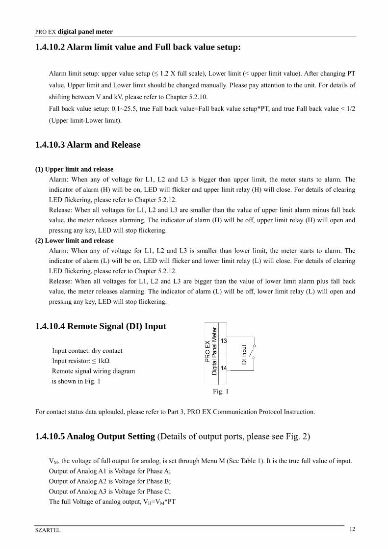
1.4.10.4 Remote Signal (DI) Input
Input contact: dry contact
Input resistor: ≤ 1kΩ
Remote signal wiring diagram
is shown in Fig. 1
Fig. 1
For contact status data uploaded, please refer to Part 3, PRO EX Communication Protocol Instruction.
1.4.10.5 Analog Output Setting (Details of output ports, please see Fig. 2)
VM, the voltage of full output for analog, is set through Menu M (See Table 1). It is the true full value of input.
Output of Analog A1 is Voltage for Phase A;
Output of Analog A2 is Voltage for Phase B;
Output of Analog A3 is Voltage for Phase C;
The full Voltage of analog output, VH=VM*PT

PRO EX digital panel meter
SZARTEL 13
1.4.10.6 Wiring Diagram
Fig. 2 PRO EX U53 3P4W
Note: When it is 3P3W, Line N can not be connected and Terminal 7# (N) is short circuited with Terminal 9# (L2)
1.4.10.7 Display Panel
(1) PRO EX U53 display panel
Fig. 3 PRO EX U53 Display Panel
(2) Indicator definition H: Upper limit indicator L: Lower limit indicator RUN: Run indicator
V: Volt unit indicator kV: Kilovolt unit indicator

PRO EX digital panel meter
SZARTEL 14
(3) Display window definition 1. 3P4W
Display window 1: L1 Voltage; Display window 2: L2 Voltage; Display window 3: L3 Voltage
2. 3W3P
Display window 1: L12 Voltage; Display window 2: L23 Voltage; Display window 3: L31 Voltage
3. When the meter goes into setup interface, display window 1 will show function items (See Table 1), display
window 2 will show function setting values and display window 3 will not show.
4. When the meter is running, the units can be shifted automatically.
1.4.11 PRO EX I53 AC Current Panel Meter
1.4.11.1 Technical Data
Connection: 3P
Input Current: 0~5A
CT Scope: 0.1~6500
1.4.11.2 Alarm Limit Value and Full Back Value Setup
Alarm limit setup: upper value setup (≤ 1.2 X full scale), Lower limit (< upper limit value). After changing CT
value, Upper limit and Lower limit should be changed manually. Please pay attention to the unit. For details of
shifting between A and KA, please refer to Chapter 5.2.10.
Fall back value setup: 0.001~0.255, true Fall back value=Fall back value setup*CT, and true Fall back value <
1/2 (Upper limit-Lower limit).
1.4.11.3 Alarm and Release
(1) Upper limit and release Alarm: When any of Current, I1, I2 or I3 is bigger than upper limit, the meter starts to alarm. The indicator of
alarm (H) will be on, LED will flicker and upper limit relay (H) will close. For details of clearing LED
flickering, please refer to Chapter 5.2.12.
Release: When all Currents, I1, L2 and L3 are smaller than the value of upper limit alarm minus fall back value,
the meter releases alarming. The indicator of alarm (H) will be off, upper limit relay (H) will open and pressing
any key, LED will stop flickering.
(2) Lower limit and release Alarm: When any of Current, I1, I2 or I3 is smaller than lower limit, the meter starts to alarm. The indicator of
alarm (L) will be on, LED will flicker and lower limit relay (L) will close. For details of clearing LED
flickering, please refer to Chapter 5.2.12.
Release: When all Currents, I1, L2 and L3 are bigger than the value of lower limit alarm plus fall back value,
the meter releases alarming. The indicator of alarm (L) will be off, lower limit relay (L) will open and pressing
any key, LED will stop flickering.
PRO EX digital panel meter
SZARTEL 15
1.4.11.4 Remote Signal (DI) Input (Wiring diagram is shown in Fig. 1)
Input contact: dry contact
Input resistor: ≤1kΩ
For contact status data uploaded, please refer to Part 3, PRO EX Communication Protocol Instruction.
1.4.11.5 Analog Output Setting (Details of output ports, please see Fig. 4)
IM, the Current of full output for analog, is set through Menu N (See Table 1). It is the true full value of input.
Output of Analog A1 is Current for Phase A;
Output of Analog A2 is Current for Phase B;
Output of Analog A3 is Current for Phase C;
The full Current of analog output, IH=IM*CT
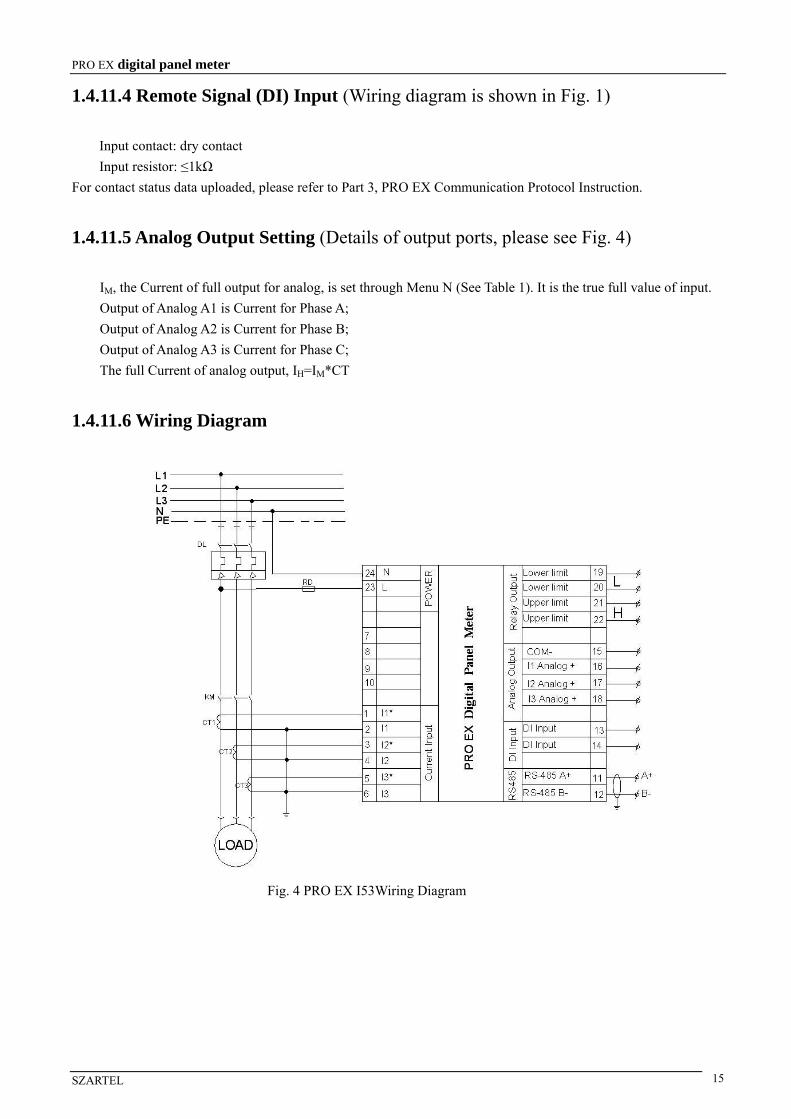
1.4.11.6 Wiring Diagram
Fig. 4 PRO EX I53Wiring Diagram

PRO EX digital panel meter
SZARTEL 16
1.4.11.7 Display Panel
(1) PRO EX I53 display panel
Fig. 5 PRO EX I53 Display Panel
(2) Indicator definition H: Upper limit indicator L: Lower limit indicator RUN: Run indicator
A: Ampere unit indicator kA: Kilo ampere unit indicator
(3) Display window definition 1. Display window 1: I1 Current; Display window 2: I2 Current; Display window 3: I3 Current
2. When the meter goes into setup interface, display window 1 will show function items (See Table 1), display
window 2 will show function setting values and display window 3 will not show.
3. When the meter is running, the units can be shifted automatically.
1.4.12 PRO EX P53 Active Power Panel Meter
1.4.12.1 Technical Data
Connection: 3P3W, 3P4W
Input Voltage: 57.7~600VAC
Input Current: 0~5A
PT Scope: 0.1~6500
CT Scope: 0.1~6500
1.4.12.2 Alarm Limit Value and Full Back Value Setup
Alarm limit setup: upper value setup (≤ 1.2 X full scale), Lower limit (< upper limit value). After changing PT
and CT value, Upper limit and Lower limit should be changed manually. Please pay attention to the unit. For
details of shifting between KW and MW, please refer to Chapter 5.2.10.
Fall back value setup: 0.1~25.5, true Fall back value=Fall back value setup*PT*CT, and true Fall back value <
1/2 (Upper limit-Lower limit).
PRO EX digital panel meter
SZARTEL 17
1.4.12.3 Alarm and Release
(1) Upper limit and release
Alarm: When total Power, P is bigger than upper limit, the meter starts to alarm. The indicator of alarm (H) will
be on, LED will flicker and upper limit relay (H) will close. For details of clearing LED flickering, please refer
to Chapter 5.2.12.
Release: When total Power, P is smaller than the value of upper limit alarm minus fall back value, the meter
releases alarming. The indicator of alarm (H) will be off, upper limit relay (H) will open and pressing any key,
LED will stop flickering.
(2) Lower limit and release
Alarm: When total Power, P is smaller than lower limit, the meter starts to alarm. The indicator of alarm (L)
will be on, LED will flicker and lower limit relay (L) will close. For details of clearing LED flickering, please
refer to Chapter 5.2.12.
Release: When total Power, P is bigger than the value of lower limit alarm plus fall back value, the meter
releases alarming. The indicator of alarm (L) will be off, lower limit relay (L) will open and pressing any key,
LED will stop flickering.
1.4.12.4 Remote Signal (DI) Input
Input contact: dry contact
Input resistor: ≤1kΩ
Remote signal wiring diagram is shown in Fig. 1
For contact status data uploaded, please refer to Part 3, PRO EX Communication Protocol Instruction.
1.4.12.5 Analog Output Setting (Details of output ports, please see Fig. 6)
PM, the power of full output for analog, is set through Menu Q (See Table 1). It is the true full power value of
input.
VM, the voltage of full output for analog, is set through Menu M (See Table 1). It is the true full value of
input.
IM, the voltage of full output for analog, is set through Menu N (See Table 1). It is the true full value of input.
Output of Analog A1 is total Power;
Output of Analog A2 is Voltage for Phase A (Phase A is default, which can be set through Menu M by user.)
Output of Analog A3 is Current for Phase A (Phase A is default, which can be set through Menu N by user.)
The full Power of analog output, PH=PM*PT*CT
The full Voltage of analog output, VH=VM*PT
The full Current of analog output, IH=IM*CT

PRO EX digital panel meter
SZARTEL 18
1.4.12.6 Wiring Diagram
Fig.6 PRO EX P53/Q53/S52 3P4W
Note: When it is 3P3W, Line N can not be connected. Terminal 7# (N) is short circuited with Terminal 9# (L2) and B (I2) phase current can be connected or not.
1.4.12.7 Display Panel
(1) PRO EX P53 display panel
Fig. 7 PRO EX P53 Display Panel
(2) Indicator definition RUN: Run indicator. Indicator on means the system runs well.
H: Upper limit indicator L: Lower limit indicator
L1: Display information of display window 2 and display window 3. When L1 is on under 3P4W, display
window 2 shows Voltage of L1 and display window 3 shows Current I1, when under 3P3W, display window 2
shows Voltage of L12 and display window 3 shows Current I1.
L2: Display information of display window 2 and display window 3. When L2 is on under 3P4W, display
window 2 shows Voltage of L2 and display window 3 shows Current I2, when under 3P3W, display window 2
shows Voltage of L23 and display window 3 shows Current I2.
L3: Display information of display window 2 and display window 3. When L3 is on under 3P4W, display
window 2 shows Voltage of L3 and display window 3 shows Current I3, when under 3P3W, display window 2

PRO EX digital panel meter
SZARTEL 19
shows Voltage of L31 and display window 3 shows Current I3.
kW: Kilowatt unit indicator MW: Megawatt unit indicator
V: Volt unit indicator kV: Kilovolt unit indicator
A: Ampere unit indicator kA: Kilo ampere unit indicator
(3) Display window definition 1. Display window 1: Total Active Power; Display window 2: L1, L2 and L3 show one by one repeatedly
(3P4W), L12, L23 and L31 show one by one repeatedly (3P3W); Display window 3: I1, I2 and I3 show one by
one repeatedly
2. When the meter goes into setup interface, display window 1 will show function items (See Table 1), display
window 2 will show function setting values and display window 3 will not show.
3. When the meter is running, the units can be shifted automatically.
1.4.13 PRO EX Q53 Reactive Power Panel Meter
1.4.13.1 Technical Data
Connection: 3P3W, 3P4W
Input Voltage: 57.7~600VAC
Input Current: 0~5A
PT Scope: 0.1~6500
CT Scope: 0.1~6500
1.4.13.2 Alarm Limit Value and Full Back Value Setup
Alarm limit setup: upper value setup (≤ 1.2 X full scale), Lower limit (< upper limit value). After changing PT
and CT value, Upper limit and Lower limit should be changed manually. Please pay attention to the unit. For
details of shifting between Kvar and Mvar, please refer to Chapter 5.2.10.
Fall back value setup: 0.1~25.5, true Fall back value=Fall back value setup*PT*CT, and true Fall back value <
1/2 (Upper limit-Lower limit).
1.4.13.3 Alarm and Release
(1) Upper limit and release Alarm: When total Power, Q is bigger than upper limit, the meter starts to alarm. The indicator of alarm (H)
will be on, LED will flicker and upper limit relay (H) will close. For details of clearing LED flickering, please
refer to Chapter 5.2.12.
Release: When total Power, Q is smaller than the value of upper limit alarm minus fall back value, the meter
releases alarming. The indicator of alarm (H) will be off, upper limit relay (H) will open and pressing any key,
LED will stop flickering.
(2) Lower limit and release Alarm: When total Power, Q is smaller than lower limit, the meter starts to alarm. The indicator of alarm (L)
will be on, LED will flicker and lower limit relay (L) will close. For details of clearing LED flickering, please
PRO EX digital panel meter
SZARTEL 20
refer to Chapter 5.2.12.
Release: When total Power, Q is bigger than the value of lower limit alarm plus fall back value, the meter
releases alarming. The indicator of alarm (L) will be off, lower limit relay (L) will open and pressing any key,
LED will stop flickering.
1.4.13.4 Remote Signal (DI) Input
Input contact: dry contact
Input resistor: ≤1kΩ
Remote signal wiring diagram is shown in Fig. 1
For contact status data uploaded, please refer to Part 3, PRO EX Communication Protocol Instruction.
1.4.13.5 Analog Output Setting (Details of output ports, please see Fig. 6)
QM, the power of full output for analog, is set through Menu R (See Table 1). It is the true full power value of
input.
VM, the voltage of full output for analog, is set through Menu M (See Table 1). It is the true full value of
input.
IM, the voltage of full output for analog, is set through Menu N (See Table 1). It is the true full value of input.
Output of Analog A1 is total Power;
Output of Analog A2 is Voltage for Phase A (Phase A is default, which can be set through Menu M by user.)
Output of Analog A3 is Current for Phase A (Phase A is default, which can be set through Menu N by user.)
The full Power of analog output, QH=QM*PT*CT
The full Voltage of analog output, VH=VM*PT
The full Current of analog output, IH=IM*CT
1.4.13.6 Wiring Diagram
The wiring diagram of PRO EX Q53 is as shown in Fig. 6.
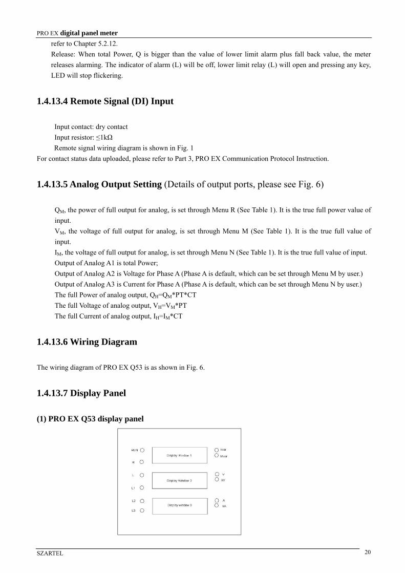
1.4.13.7 Display Panel
(1) PRO EX Q53 display panel

PRO EX digital panel meter
SZARTEL 21
Fig. 8 PRO EX P53 Display Panel
(2) Indicator definition RUN: Run indicator. Indicator on means the system runs well.
H: Upper limit indicator L: Lower limit indicator
L1: Display information of display window 2 and display window 3. When L1 is on under 3P4W, display
window 2 shows Voltage of L1 and display window 3 shows Current I1, when under 3P3W, display window 2
shows Voltage of L12 and display window 3 shows Current I1.
L2: Display information of display window 2 and display window 3. When L2 is on under 3P4W, display
window 2 shows Voltage of L2 and display window 3 shows Current I2, when under 3P3W, display window 2
shows Voltage of L23 and display window 3 shows Current I2.
L3: Display information of display window 2 and display window 3. When L3 is on under 3P4W, display
window 2 shows Voltage of L3 and display window 3 shows Current I3, when under 3P3W, display window 2
shows Voltage of L31 and display window 3 shows Current I3.
kvar: Kilovar unit indicator Mvar: Megavar unit indicator
V: Volt unit indicator kV: Kilovolt unit indicator
A: Ampere unit indicator kA: Kilo ampere unit indicator
(3) Display window definition 1. Display window 1: Total Reactive Power; Display window 2: L1, L2 and L3 show one by one repeatedly
(3P4W), L12, L23 and L31 show one by one repeatedly (3P3W); Display window 3: I1, I2 and I3 show one by
one repeatedly
2. When the meter goes into setup interface, display window 1 will show function items (See Table 1), display
window 2 will show function setting values and display window 3 will not show.
3. When the meter is running, the units can be shifted automatically.
1.4.14 PRO EX S52 Combination Panel Meter for Active/Reactive Power
1.4.14.1 Technical Data
Connection: 3P3W, 3P4W
Input Voltage: 57.7~600VAC
Input Current: 0~5A
PT Scope: 0.1~6500
CT Scope: 0.1~6500
1.4.14.2 Alarm Limit Value and Full Back Value Setup
The user can choose Active Power or Reactive Power as alarm value. (See Z3 of Table 1)
Alarm limit setup: upper value setup (≤1.2 X full scale), Lower limit (< upper limit value). After changing PT
and CT value, Upper limit and Lower limit should be changed manually. Please pay attention to the unit. For
details of shifting between KW and MW or Kvar and Mvar, please refer to Chapter 5.2.10.
Fall back value setup: 0.1~25.5, true Fall back value=Fall back value setup*PT*CT, and true Fall back value
< 1/2 (Upper limit-Lower limit).

PRO EX digital panel meter
SZARTEL 22
1.4.14.3 Alarm and Release
(1) Upper limit and release Alarm: When total Power, P or Q (Set through Menu N) is bigger than upper limit, the meter starts to alarm.
The indicator of alarm (H) will be on, LED will flicker and upper limit relay (H) will close. For details of
clearing LED flickering, please refer to Chapter 5.2.12.
Release: When total Power, P or Q is smaller than the value of upper limit alarm minus fall back value, the
meter releases alarming. The indicator of alarm (H) will be off, upper limit relay (H) will open and pressing
any key, LED will stop flickering.
(2) Lower limit and release Alarm: When total Power, P or Q (Set through Menu N) is smaller than lower limit, the meter starts to alarm.
The indicator of alarm (L) will be on, LED will flicker and lower limit relay (L) will close. For details of
clearing LED flickering, please refer to Chapter 5.2.12.
Release: When total Power, P or Q is bigger than the value of lower limit alarm plus fall back value, the meter
releases alarming. The indicator of alarm (L) will be off, lower limit relay (L) will open and pressing any key,
LED will stop flickering.
1.4.14.4 Remote signal (DI) input (Wiring diagram is shown in Fig. 1)
Input contact: dry contact
Input resistor: ≤1kΩ
Remote signal wiring diagram is shown in Fig. 1
For contact status data uploaded, please refer to Part 3, PRO EX Communication Protocol Instruction.
1.4.14.5 Analog Output Setting (Details of output ports, please see Fig. 6)
PM, the power of full output for analog, is set through Menu Q (See Table 1). It is the true full power value of
input.
QM, the power of full output for analog, is set through Menu R (See Table 1). It is the true full power value of
input.
IM, the voltage of full output for analog, is set through Menu N (See Table 1). It is the true full value of input.
Output of Analog A1 is total Active Power;
Output of Analog A2 is total Reactive Power;
Output of Analog A3 is Current for Phase A (Phase A is default, which can be set through Menu N by user.)
The full Active Power of analog output, PH=PM*PT*CT
The full Reactive Power of analog output, QH=QM*PT*CT
The full Current of analog output, IH=IM*CT
1.4.14.6 Wiring Diagram
The wiring diagram of PRO EX S52 is as shown in Fig. 6.
PRO EX digital panel meter
SZARTEL 23
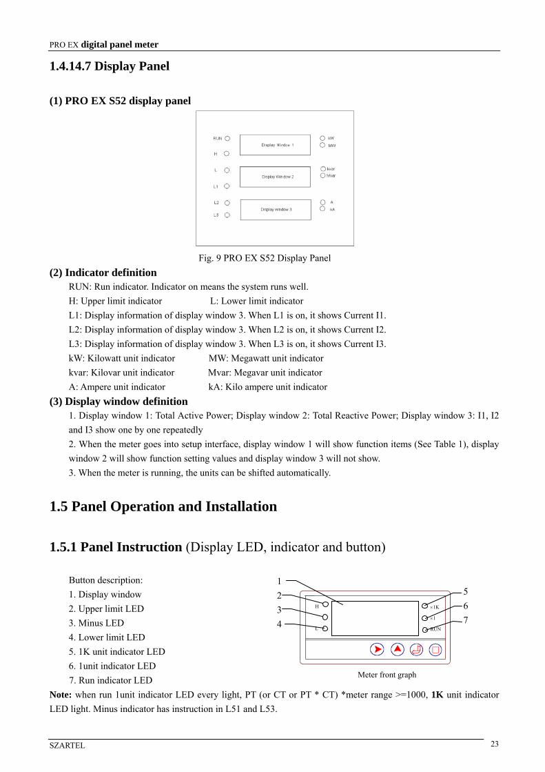
1.4.14.7 Display Panel
(1) PRO EX S52 display panel
Fig. 9 PRO EX S52 Display Panel
(2) Indicator definition RUN: Run indicator. Indicator on means the system runs well.
H: Upper limit indicator L: Lower limit indicator
L1: Display information of display window 3. When L1 is on, it shows Current I1.
L2: Display information of display window 3. When L2 is on, it shows Current I2.
L3: Display information of display window 3. When L3 is on, it shows Current I3.
kW: Kilowatt unit indicator MW: Megawatt unit indicator
kvar: Kilovar unit indicator Mvar: Megavar unit indicator
A: Ampere unit indicator kA: Kilo ampere unit indicator
(3) Display window definition 1. Display window 1: Total Active Power; Display window 2: Total Reactive Power; Display window 3: I1, I2
and I3 show one by one repeatedly
2. When the meter goes into setup interface, display window 1 will show function items (See Table 1), display
window 2 will show function setting values and display window 3 will not show.
3. When the meter is running, the units can be shifted automatically.
1.5 Panel Operation and Installation
1.5.1 Panel Instruction (Display LED, indicator and button)
Button description: 1. Display window
2. Upper limit LED
3. Minus LED
4. Lower limit LED
5. 1K unit indicator LED
6. 1unit indicator LED
7. Run indicator LED
Note: when run 1unit indicator LED every light, PT (or CT or PT * CT) *meter range >=1000, 1K unit indicator
LED light. Minus indicator has instruction in L51 and L53.
1K
1
RUN
H
L
Meter front graph
1
2
3
4
5
6
7

PRO EX digital panel meter
SZARTEL 24
1.5.2 Key Description
1. —— In the parameter modification mode, the cursor moves to the right digit.
2. —— ‘+’button. In the parameter modification mode, the digit adds 1.
When setting Baud rate, you can press the key to shift between 19200, 9600, 4800, 2400, and 1200.
When setting connection, you can press the key to shift between 3P3W and 3P4W.
3. —— ‘-’button. In the parameter modification mode, the digit reduces 1. When setting Baud rate, you can press the key to shift between 19200, 9600, 4800, 2400, and 1200.
When setting connection, you can press the key to shift between 3P3W and 3P4W.
When setting alarm value (S32), you can press the key to shift between P and Q. (Only applies to
EX53 series)
4. —— In the setup mode, when in the main menu, the meters enter in the parameter modification status.
5. —— In the setup mode, when the main menu appears, the meter scrolls to the next submenu by
pressing it. In the parameter modification mode, the meter exits the current setup without saving
parameter and return to the main menu by pressing it.
6. —— In the setup mode, when the main menu appears, press the key, it will go to next page. In the
parameter modification mode, press the key to cancel or save modification and go back to main
menu. (Only applies to EX 53 series)
7. —— In the setup mode, when the main menu appears, press the key to enter the menu and go to
parameters modification page. In the parameter modification mode, press the key to save
modification and go to next page of main menu. (Only applies to EX 53 series)
8. + —— Press and hold both keys over 3 seconds, meter changes to setup page from run status.
9 + —— Press and hold both keys over 3 seconds, meter changes to setup page from run status.
(Only applies to EX 53 series)
10. + —— The meter metric unit changes between 1 and 1K.
11. + —— When alter parameter, the cursor loop moves to the right digit.
When Alarm limit, relieve alarm.
12. + —— In the parameter modification mode, press and hold both keys over 3 seconds, the cursor
loop moves to the right digit. In alarm status, press and hold both keys over 3 seconds,
the flicker of LED stops. (Only applies to EX 53 series)
13. + —— Press and hold both keys over 3 seconds, appears, the user is required to
input password (the initial password is “1111”). Pressing to confirm and enters the
setup mode.

PRO EX digital panel meter
SZARTEL 25
1.5.3 Example
Example 1:
PRO EX U51 AC Voltage digital panel meter, with 0~600V input Voltage and RS485. Meter address is 5, baud rate
9600bps. When meter input Voltage>5000V upper limit alarm, and < 4950V upper limit, relay open. When meter
input Voltage<1000Vlower limit alarm, and >1050V lower limit, relay open. When analog full range match along
with Voltage is 500V, the password is changed from 0000 to 1234. The steps are as follows.
1. Press and hold + key for 3 S, till appears, the 1st digit shimmers, press to "I"
appears, then press key to the 2nd digit, press key to "1"appears, and so on when the 4 digits are all “1”,
press key to Confirm the setting, Table 1 menu A is appears.
2. When item 1- A shown as in the table 1-A shows, press key or key to modify the meter address to
, press key to confirm the current setup and the meter goes to the item B.
3. When item 1- B is baud rate appears, press key to choose the baud rate and press key to
confirm.
4. Press to display item 1-I, and press key to enter PT setup. Press or key to modify CT to
, and press key to confirm.
5. Press menu 1-C is appears, and press key to enter upper limit value, press or key to
modify to “ ” Confirm the setting.
6. Press menu 1-D is appears, and press key to enter lower limit value, press or key to
modify to “ ” Confirm the setting.
7. Press menu 1-E is appears, and press key to enter Fall back value, Press or key
to“ ” Confirm the setting.
8. Press menu 1-M is appears, and press key to modify the max analog value with AC current input,
Press or key to the “ ” Confirm the setting.
9. Press menu 1-F is appears, and press key to modify “ ” Confirm the setting.
10. Press menu 1-G is appears then press key to exit the setting up.
(Note: Please remember the password, if the password is lost, please contact manufacturer).

PRO EX digital panel meter
SZARTEL 26
Example 2:
PRO EX P53 Active Power panel meter, with 57.7-600VAC input voltage, 0-5A input current, 3P4W, and RS485.
When meter address is 5, baud rate 9600bps, PT 1, CT 1, upper limit 10kW, lower limit 300W, fall back value 20,
and analog full value for Voltage 600V, for Current 5A, for Active Power 9kW, the password is changed from 1111
to 0001. The steps are as follows.
1. Press and hold + key for 3 S, till appears, the 1st digit shimmers, press till "1" appears,
then press key and move to the 2nd digit, press key till "1" appears, and so on. When the 4 digits are all
“1”, press key to save the setting, Table 1 menu A is appears. (In setup mode, the first row LEDs indicate
functions, while the second ones indicate parameters set)
2. When menu A shows, press key to modify the meter address to , press key to save the current
setup and the meter goes to the menu B.
3. When menu B shows, it indicates Baud Rate. Press key till , then press to save.
4. When menu I shows, it indicates PT value. Press till , then press to save.
5. When menu J shows, it indicates CT value. Press till , then press to save.
6. When menu Z2 shows, it indicates phase options. Press till , then press to save.
7. When menu C shows, it indicates upper limit value. Press till , then press and to active
kW indicator, and press to save.
8. When menu D shows, it indicates upper limit value. Press till , then press and till kW and
MW indicators are off, and press to save. When kW and MW are off, it indicates W.
9. When menu E shows, it indicates fall back value. Press till .
10. When menu Z1 shows, press to go to menu M. It indicates analog full value of voltage. Press till
, then press to save.
11. After setting analog full value of voltage, then go to menu N. It indicates analog full value of current. Press
till , then press to save.
12. After setting analog full value of current, then go to menu Q. It indicates analog full value of active power. Press
till , then press to save.
13. When menu F shows, it indicates password. Press till , then press to save. Now the
password is changed to . Please remember the password. If forget, please contact manufacturer.
14. When menu G shows, press to exit setup page.

PRO EX digital panel meter
SZARTEL 27
Table 1: Menu display List
A Com. address setup Scope: 1~255
B
Baud rate setup 19200, 9600, 4800, 2400, 1200 optional
table
C Alarm Upper value setup
D
Alarm Lower Value setup
E Alarm fall back value Scope: 0~1/2 (Upper limit-Lower limit)
F
Parameter modification setup Enter parameter modification setup
G Exit setup mode Exit setup
H Error
I PT setup Scope: 0.1~6500
J CT setup Scope: 0.1~6500
K The inductive district Lower limit Select type L meter setup
L The capacitive district Lower limit Select type C meter setup
M Analog full range match along with AC
Voltage input Scope: 0~600V
N Analog full range match along with AC
current input Scope: 0~5A
O Analog full range match along with DC
Voltage input Scope: 0~600V
P Analog full range match along with DC
Current input Scope: -75~75mV
Q Analog full range match along with Active
Power input Scope: 0~3000W
R Analog full range match along with
Freqency input Scope: 45~65Hz , 360~440Hz
S
Temperature transducer type select Enter next menu, PT100, PT50, Cu100,
Cu50 select
T
Temperature transducer PT100
U
Temperature transducer PT50
V
Temperature transducer Cu100
W
Temperature transducer Cu50
X Analog full range match along with
temperature input

PRO EX digital panel meter
SZARTEL 28
1.5.4 Meter Installation
1.5.4.1 Installation for EX51 Series
1) Please install the meter in the hole of the panel, and install the fastening and supporting components on the side
of meter.
2) Fasten the screw clockwise so that the meter is in the panel.
1.5.4.2 Installation for EX53 Series
1) Put support 1 on the side 2 of meter
2) Fix the meter on the panel 3.
Front view Side view Installation size
Fasten Bolt Supporting compon. Meter Panel
2
1
3

PRO EX digital panel meter
SZARTEL 29
1.6 PRO EX Operation and Trouble Shooting
1.6.1 How to Operate PRO EX Digital Meter Properly?
We suggest the user use the product under the right environment according to the user manual. Otherwise, the
user is responsible for the risks occurred.
1.6.2 Warning
1) Please do not disassemble the product. If any problem occurs, please contact after-sales service of Artel
immediately.
2) Please make sure the environment temperature is -10~55.
3) Please connect the wires correctly, referring to the wiring diagram and make sure input values do not exceed
1.2 times of specified measurement scopes.
1.6.3 Trouble Shooting
No. Trouble Trouble-shooting
1 No display when the
power is on
1. Check if the power line is connected with the auxiliary supply input
terminal.
2. Check if the power line is connected to socket closely.
3. According to your mode, check if the auxiliary supply is 85V-265VAC/DC
4. If still no display, please contact Artel.
`2 Incorrect measured
values
1. Check if the input wires are connected to the corresponding input terminals
correctly and closely.
2. If the product is PRO EX U51/U53, please make sure PT value is set
correctly.
3. If the product is PRO EX I51/DI51/I53, please make sure CT value is set
correctly
4. If the product is PRO EX P51/P53/Q53/S52, please make sure PT and CT
values are set correctly
5. If the product is PRO EX T51, please make sure the type of temperature
sensor is the same as the one connected.
6. If the value is still incorrect, please contact Artel.
3 No access to setup
mode
1. Make sure the password is correct. The default password is 1111.
2. If you forget the reset password, please contact Artel.
4 No analog output 1. Make sure the product that you purchased has analog output function.
2. Check connecting lines are connected to corresponding analog output
terminals correctly and closely.
3. If the product is PRO EX U51/U53, please make sure analog full value
(UoUt) is correct. For example, the input voltage is 57.7~600VAC and the
analog output is 4~20mA. If UoUt is 500V, the analog output will be 20mA

PRO EX digital panel meter
SZARTEL 30
when the input voltage is 500VAC.
4. If the product is PRO EX I51/53, please make sure analog full value (IoIt)
is correct.
5. If the product is PRO EX DU51, please make sure analog full value
(DUot) is correct.
6. If the product is PRO EX DI51, please make sure analog full value (DIot)
is correct.
7. If the product is PRO EX P51, please make sure analog full value (PoUt) is
correct.
8. If the product is PRO EX F51, please make sure analog full value (FoUt) is
correct.
9. If the product is PRO EX T51, please make sure analog full value (toUt) is
correct.
10. If the product is PRO EX P53, please make sure analog full values (PoUt,
UoUt and IoUt) are correct.
11. If the product is PRO EX Q53, please make sure analog full values (qoUt,
UoUt and IoUt) are correct.
12. If the product is PRO EX S52, please make sure analog full values (qoUt,
PoUt and IoUt) are correct.
13. If you make sure the wiring connecting and settings are correct, please
contact Artel.
5 Communication can
not connect
1. Make sure the product that you purchased has RS485 function.
2. Check if the communication line is connected to corresponding RS-485
communication terminal correctly and closely. Please make sure the negative
and positive terminals are connected correctly.
3. Check if the Baud Rate and address of meter are the same as the ones of
PC when the meter communicates with PC.
4. If you make sure the wiring connecting and settings are correct, please
contact Artel.
6 Alarm waning fault 1. Make sure the product that you purchased has relay output function.
2. Check connecting lines are connected to corresponding relay alarm output
terminals correctly and closely.
3. Check if the upper limit and lower limit values fit for the requirement.
4. If you make sure the wiring connecting and settings are correct, please
contact Artel.
PRO EX digital panel meter
SZARTEL 31
II. Software Instruction
2.1 Function Description
The PRO EX transducer can read sampling data , real time monitoring and displaying the data, and remote set
up parameters, including communication Address, baud rat, PT, CT, upper/lower limit, Fall back value and wiring
connections. (Different products have different parameters)
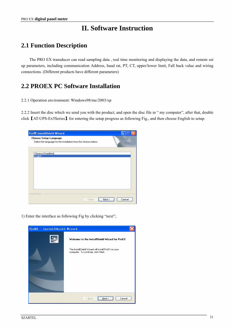
2.2 PROEX PC Software Installation
2.2.1 Operation environment: Windows98/me/2003/xp
2.2.2 Insert the disc which we send you with the product, and open the disc file in “ my computer”, after that, double
click【AT-UPS-Ex5Series】for entering the setup progress as following Fig., and then choose English to setup.
1) Enter the interface as following Fig by clicking “next”;
PRO EX digital panel meter
SZARTEL 32
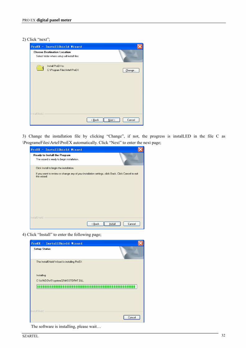
2) Click “next”;
3) Change the installation file by clicking “Change”, if not, the progress is instalLED in the file C as
\ProgrameFiles\Artel\ProEX automatically. Click “Next” to enter the next page;
4) Click “Install” to enter the following page;
The software is installing, please wait…

PRO EX digital panel meter
SZARTEL 33
5) The following interface will appear when the installation is finished;
6) Pro EX PC software is instalLED successfully by clicking“Finish”.
2.2.3 Start PRO EX for enter in data collecting operation interface as following Fig.: there are five standard value
for chosen in baud rate option that default value is 9600bps; connection overtime option is used in setting up
connection responds time. For example: the connection overtime is set as 200ms in the Fig., it means that if the
firmware doesn’t responds to PC when the PC send signal to it, then PC will send signal circularly.
2.2.3.1. The up right indicator turns green when click , then following interface appears. Please click COM2
if RS485 connecting with it, and then click , the following interface appears. Please make sure that click
first,and then click for searching.
PRO EX digital panel meter
SZARTEL 34
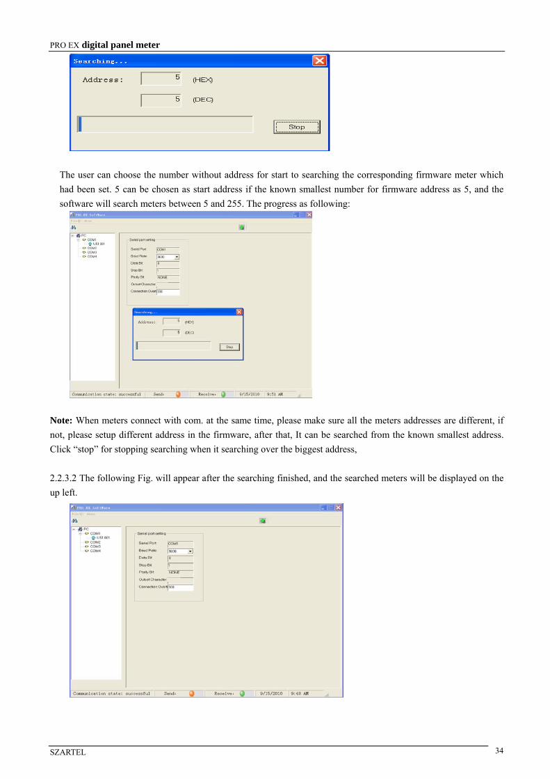
The user can choose the number without address for start to searching the corresponding firmware meter which
had been set. 5 can be chosen as start address if the known smallest number for firmware address as 5, and the
software will search meters between 5 and 255. The progress as following:
Note: When meters connect with com. at the same time, please make sure all the meters addresses are different, if
not, please setup different address in the firmware, after that, It can be searched from the known smallest address.
Click “stop” for stopping searching when it searching over the biggest address,
2.2.3.2 The following Fig. will appear after the searching finished, and the searched meters will be displayed on the
up left.
PRO EX digital panel meter
SZARTEL 35
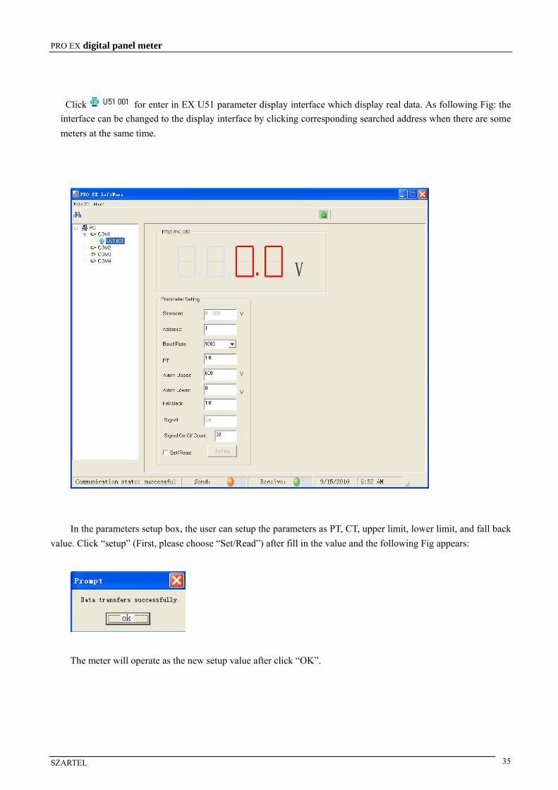
Click for enter in EX U51 parameter display interface which display real data. As following Fig: the
interface can be changed to the display interface by clicking corresponding searched address when there are some
meters at the same time.
In the parameters setup box, the user can setup the parameters as PT, CT, upper limit, lower limit, and fall back
value. Click “setup” (First, please choose “Set/Read”) after fill in the value and the following Fig appears:
The meter will operate as the new setup value after click “OK”.
PRO EX digital panel meter
SZARTEL 36
III. PRO EX Communication Protocol
3.1 MODBUS RTU Protocol
The data format as:
Address (8bit) + function code (8bit) + Register (16bit) + Data area (N×8bit) + CRCH + CRCL
Address code: The 1st byte. The byte indicates the serving meter shall receive the information from the master
meter. Every meter can only have 1 address code. Sending and receiving information must address to each meter’s
own address code. The master meter shall indicate the address code for the serving meter, and the serving meter
shall indicate the reply address code.
Function code: The 2nd byte. Modbus Protocol defines that the function no. is between 1 and 127. Pro Ex use a part
of the code (see table blow). The master meter commands the serving meter the executions by sending the function
code. When the serving meter receives the commands, it responds the master meter by sending back the same
function code.
Register: The designated data storing place.
Data area: Data areas are different according to different function code, different sending or responding command.
The data in each register is 2 bytes, indicated as: No. of register H + No. of registering data L + bytes + read/write
data 1H + read/write data 1L + read/write data 2H + read/write data 2L…
CRC code: 2 bytes error checking code. First send high 8bit, then send low 8bit.
3.2 PRO EX Functional Code
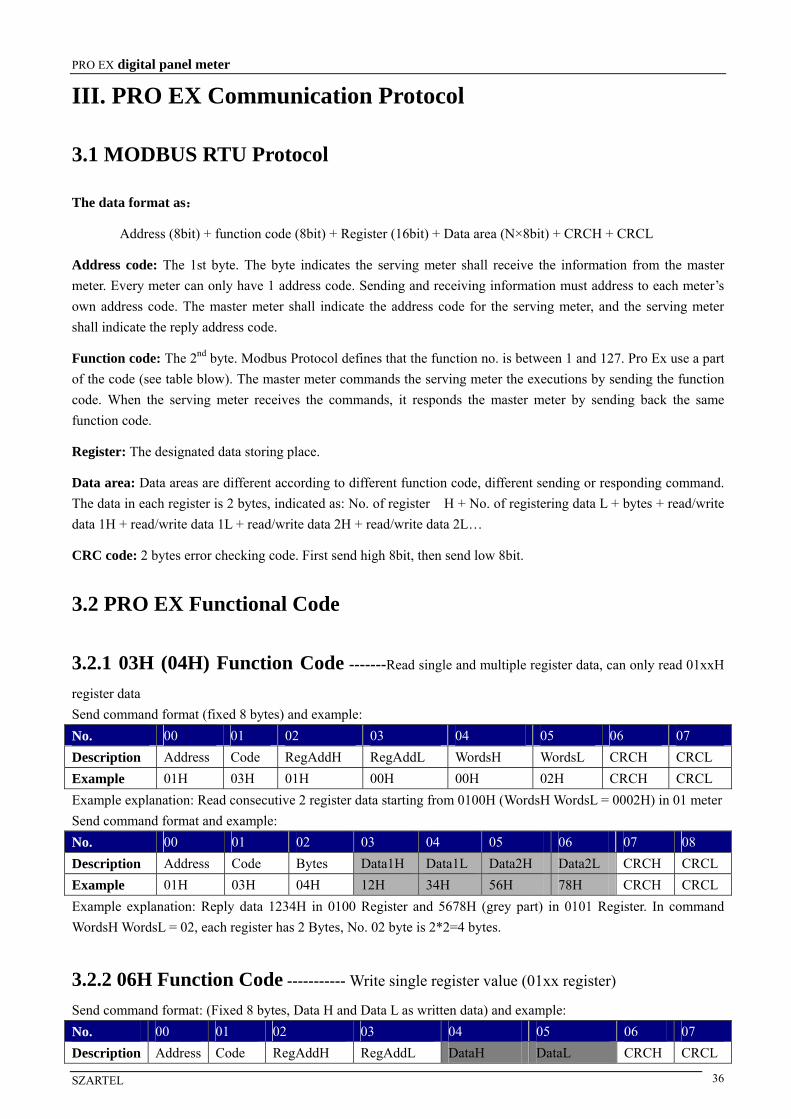
3.2.1 03H (04H) Function Code -------Read single and multiple register data, can only read 01xxH
register data
Send command format (fixed 8 bytes) and example:
No. 00 01 02 03 04 05 06 07
Description Address Code RegAddH RegAddL WordsH WordsL CRCH CRCL
Example 01H 03H 01H 00H 00H 02H CRCH CRCL
Example explanation: Read consecutive 2 register data starting from 0100H (WordsH WordsL = 0002H) in 01 meter
Send command format and example:
No. 00 01 02 03 04 05 06 07 08
Description Address Code Bytes Data1H Data1L Data2H Data2L CRCH CRCL
Example 01H 03H 04H 12H 34H 56H 78H CRCH CRCL
Example explanation: Reply data 1234H in 0100 Register and 5678H (grey part) in 0101 Register. In command
WordsH WordsL = 02, each register has 2 Bytes, No. 02 byte is 2*2=4 bytes.
3.2.2 06H Function Code ----------- Write single register value (01xx register)
Send command format: (Fixed 8 bytes, Data H and Data L as written data) and example:
No. 00 01 02 03 04 05 06 07
Description Address Code RegAddH RegAddL DataH DataL CRCH CRCL

PRO EX digital panel meter
SZARTEL 37
Example 01H 06H 01H 00H 12H 34H CRCH CRCL
Example explanation: Write 1234H in meter 01's 0100 register.
Send command: (total 8 bytes): If writing data is successfully, then send back the same data.
No. 00 01 02 03 04 05 06 07
Description Address Code RegAddH RegAddL DataH DataL CRCH CRCL
Example 01H 06H 01H 00H 12H 34H CRCH CRCL
Example explanation: the meter 01 executes 03H code successfully, writing 1234H data in 0100 register.
3.2.3 10H Function Code--------Write multiple register continuously
Send command format and example:
No. 00 01 02 03 04 05 06 07 08 09 0A 0B 0C
Description Add Code RegAddH RegAddL WordsH WordsL Bytes Data1H Data1L Data2H Data2L CRCH CRCL
Example 01H 10H 01H 01H 00H 02H 04H 12H 34H 56H 78H CRCH CRCL
Example explanation: Write 2 Continuous data 1234H and 5678H in meter 01 starting from 0101 register.
Send command format and example:
No. 00 01 02 03 04 05 06 07
Instruction Address Code RegAddH RegAddL WordsH WordsL CRCH CRCL
Example 01H 10H 01H 01H 00H 02H CRCH CRCL
Example explanation: Execute command 10H successfully.
3. 2.4 99H Function Code-------- Meter searching
Send command format (fixed 8 bytes) and example:
No. 00 01 02 03 04 05 06 07
Instruction Address Code Code1H Code1L Code2H Code2L CRCH CRCL
Example 01H 99H 00H 02H 00H 02H CRCH CRCL
Example explanation: Searching No.01 Meter
Send command format (fixed 11 bytes) and example:
No. 00 01 02 03 04 05 06 07 08 09 0A
Instruction Add Code Code2 HWVerH HWVerL SWVerH SWVerL TypeH TypeL CRCH CRCL
Example 01H 99H 04H 00H 3A 00H 69 00H 00H CRCH CRCL
Example explanation: Send back data as: hardware version: V5.8, software version: V1.05, type: PRO_EXU51

PRO EX digital panel meter
SZARTEL 38
3.3 PRO EX Register Explanation (R means read, W means write)
Address
(Hex) Type Description Byte Content Register Explanation
Byte1 ―――― 0100 RW Address
Byte0 Address Meter address:1~255
Byte1 ―――― 0101 RW Baud rate
Byte0 Baud rate
0:19200 1:9600 2:4800
3:2400 4:1200。
Byte1 CTvalue H
0102 RW CT Byte0 CTvalue L
CT scope:0.1~6500,1 decimal fraction.
Registers value=CT*10,CT= Registers
value /10.
Byte1 PT H
0103 RW PT Byte0 PT L
PT scope:0.1~6500,1 decimal fraction.
Registers value=PT*10,PT= Registers
value /10.
Byte1 ――――
0104 RW mode of connection
Byte0 mode of
connection
Mode of connection (U53,P53,Q53,
S52,L51)
0:3P3W;
1:3P4W;
2:3P3W balance;(invalid for L51)
3:3P4W balance;(invalid for L51)
Byte1 Upper -limit
alarm value0105 RW
Upper-limit alarm
real number Byte0
Upper -limit
alarm value
Byte1 ――――
0106 RW Upper -limit alarm
index Byte0 index E
Upper -limit alarm data = metrical
data*10N, the highest bit of
upper-limit alarm real number is a
sign bit, 1 is Negative; 0 is Positive.
The highest bit of N byte (Byte0) is a
sign bit, 1 is Negative; -N; 0 is
Positive. Real number and index
register must be written in the same
time, but can be read separately.
Byte1 Lower-limit
alarm value
0107 RW
Lower-limit alarm
real number
Byte0 Lower-limit
alarm value
Byte1 ――――
0108 RW Lower-limit alarm
index Byte0 index N
Lower-limit alarm data = metrical
data*10N, the highest bit of lower-limit
alarm real number is a sign bit, 1 is
Negative; 0 is Positive. The highest bit
of N byte (Byte0) is a sign bit, 1 is
Negative: -N; 0 is Positive. Real
number and index register must be
written in the same time, but can be
read separately. The alarm value is C
(capacitive)/L (inductive) in PRO EX
L51.
Byte1 Fall back
value H
0109 RW Fall back value
Byte0 Fall back
value L
3 decimal fraction, Fall back value
=Register value/1000。
F51:0.01~2.55。
L51/I51/I53:.001~0.255。
Other fall back value:0.1~25.5。

PRO EX digital panel meter
SZARTEL 39
Address
(Hex) Type Description Byte Content Register Explanation
Byte1 H byte
010A RW Remote event timesByte0 L byte
Remote event times.
Byte1 Remote
mark 0/1
010B RW Remote mark/
remote status Byte0
Remote data
0/1
Byte1:
0: Remote signal back to 0 when
disconnection, back to 1 when close.
1: Remote signal back to 1 when
disconnection, back to 0 when close.
0: Byte0: (invalid when write
operation)
Normally open/closed contact 1/0:
decide by Byte1.
Byte1
the high
byte of
Metrical
data1, the
highest bit
is a sign bit
010C R Metrical data 1 real
number
Byte0
the low byte
of Metrical
data1
Byte1 ―――― 010D R
Metrical data 1
index number Byte0 Index N
Metrical data = Metrical data1*10N, the
highest bit of Metrical data1 Byte1 is a
sign bit, 1 is Negative; 0 is Positive.
The highest bit of N Byte0 is a sign bit,
1 is Negative: -N; 0 is Positive. (The
metrical data not multiply by PT/CT).
Byte1
the high
byte of
Metrical
data2, the
highest bit
is a sign bit
010E R Metrical data 2 real
number
Byte0
the low byte
of Metrical
data2
Byte1 ―――― 010F R
Metrical data 2
index number Byte0 Index N
Metrical data = metrical data 2*10N, the
highest bit of metrical data2Byte1 is a
sign bit, 1 is Negative; 0 is Positive.
The highest bit of N byte (Byte0) is a
sign bit, 1 is Negative:-N; 0 is Positive.
(The metrical data not multiply by
PT/CT).
Byte1
the high
byte of
Metrical
data3, the
highest bit
is a sign bit
0110 R Metrical data 3 real
number
Byte0
the low byte
of Metrical
data3
Metrical data = metrical data3*10N, the
highest bit of metrical data3 Bybte1 is a
sign bit, 1 is Negative; 0 is Positive.
The highest bit of N byte (Byte0) is a
sign bit, 1 is Negative; -N; 0 is Positive.
(The metrical data not multiply by
PT/CT).

PRO EX digital panel meter
SZARTEL 40
Address
(Hex) Type Description Byte Content Register Explanation
Byte1 ―――― 0111 R
Metrical data 3
index number Byte0 Index N
Byte1
the high
byte of
Metrical
data4, the
highest bit
is a sign bit
0112 R Metrical data 4 real
number
Byte0
the low byte
of Metrical
data4
Byte1 ―――― 0113 R
Metrical data 4
index number Byte0 Index N
Metrical data = metrical data4*10N, the
highest bit of metrical data 4 Bybte1 is
a sign bit, 1 is Negative; 0 is Positive.
The highest bit of N byte (Byte0) is a
sign bit, 1 is Negative; -N; 0 is Positive.
(The metrical data not multiply by
PT/CT).
Byte1
the high
byte of
Metrical
data5, the
highest bit
is a sign bit
0114 R Metrical data 5 real
number
Byte0
the low byte
of Metrical
data5
Byte1 ―――― 0115 R
Metrical data 5
index number Byte0 Index N
Metrical data = metrical data 5*10N, the
highest bit of metrical data5 Bybte1 is a
sign bit, 1 is Negative; 0 is Positive.
The highest bit of N byte (Byte0) is a
sign bit, 1 is Negative; -N; 0 is Positive.
(The metrical data not multiply by
PT/CT).
Byte1
the high
byte of
Metrical
data6, the
highest bit
is a sign bit
0116 R Metrical data 6 real
number
Byte0
the low byte
of Metrical
data6
Byte1 ―――― 0117 R
Metrical data 6
index number Byte0 Index N
Metrical data = metrical data 6*10N, the
highest bit of metrical data 6 Bybte1 is
a sign bit, 1 is Negative; 0 is Positive.
The highest bit of N byte (Byte0) is a
sign bit, 1 is Negative; -N; 0 is Positive.
(The metrical data not multiply by
PT/CT).
Byte1
the high
byte of
Metrical
data7, the
highest bit
is a sign bit
0118 R Metrical data 7 real
number
Byte0
the low byte
of Metrical
data7
0119 R Metrical data 7 Byte1 ――――
Metrical data = metrical data 7*10N, the
highest bit of metrical data 7Bybte1 is a
sign bit, 1 is Negative; 0 is Positive.
The highest bit of N byte (Byte0) is a
sign bit, 1 is Negative: -N; 0 is Positive.
(The metrical data not multiply by
PT/CT).
PRO EX digital panel meter
SZARTEL 41
Address
(Hex) Type Description Byte Content Register Explanation
index number Byte0 Index N
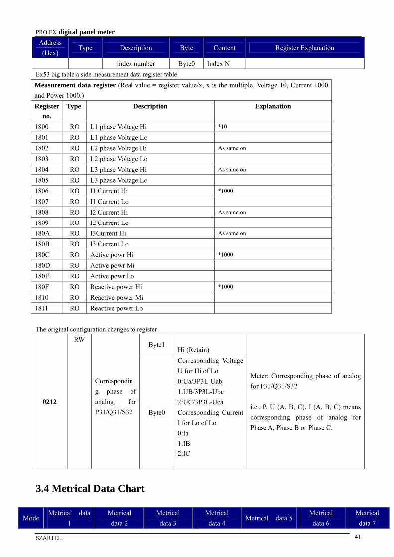
Ex53 big table a side measurement data register table
Measurement data register (Real value = register value/x, x is the multiple, Voltage 10, Current 1000
and Power 1000.)
Register
no.
Type Description Explanation
1800 RO L1 phase Voltage Hi *10
1801 RO L1 phase Voltage Lo
1802 RO L2 phase Voltage Hi As same on
1803 RO L2 phase Voltage Lo
1804 RO L3 phase Voltage Hi As same on
1805 RO L3 phase Voltage Lo
1806 RO I1 Current Hi *1000
1807 RO I1 Current Lo
1808 RO I2 Current Hi As same on
1809 RO I2 Current Lo
180A RO I3Current Hi As same on
180B RO I3 Current Lo
180C RO Active powr Hi *1000
180D RO Active powr Mi
180E RO Active powr Lo
180F RO Reactive power Hi *1000
1810 RO Reactive power Mi
1811 RO Reactive power Lo
The original configuration changes to register
Byte1
Hi (Retain)
0212
RW
Correspondin
g phase of
analog for
P31/Q31/S32
Byte0
Corresponding Voltage
U for Hi of Lo
0:Ua/3P3L-Uab
1:UB/3P3L-Ubc
2:UC/3P3L-Uca
Corresponding Current
I for Lo of Lo
0:Ia
1:IB
2:IC
Meter: Corresponding phase of analog
for P31/Q31/S32
i.e., P, U (A, B, C), I (A, B, C) means
corresponding phase of analog for
Phase A, Phase B or Phase C.
3.4 Metrical Data Chart
Mode Metrical data
1
Metrical
data 2
Metrical
data 3
Metrical
data 4 Metrical data 5
Metrical
data 6
Metrical
data 7

PRO EX digital panel meter
SZARTEL 42
Mode Metrical data
1
Metrical
data 2
Metrical
data 3
Metrical
data 4 Metrical data 5
Metrical
data 6
Metrical
data 7
U51 AC Voltage ―――― ―――― ―――― ―――― ―――― ――――
I51 AC Current ―――― ―――― ―――― ―――― ―――― ――――
DU51 DC Voltage ―――― ―――― ―――― ―――― ―――― ――――
DI51 DC Current ―――― ―――― ―――― ―――― ―――― ――――
P51S Active Power ―――― ―――― ―――― ―――― ―――― ――――
L51 Power factor ―――― ―――― ―――― ―――― ―――― ――――
F51 Power net
frequency ―――― ―――― ―――― ―――― ―――― ――――
T51 Temperature ―――― ―――― ―――― ―――― ―――― ――――
U53 AC Voltage A AC Voltage B AC Voltage C ―――― ―――― ―――― ――――
I53 AC Current A AC Current B AC Current C ―――― ―――― ―――― ――――
P53 AC Voltage A AC Voltage B AC Voltage C AC Current A AC Current B AC Current CActive
Power
Q53 AC Voltage A AC Voltage B AC Voltage C AC Current A AC Current B AC Current CReactive
Power
S52 AC Current A AC Current B AC Current C Active Power Reactive Power ―――― ――――
APPENDIX: Packing List
Meter 1unit
Fasten the screw clockwise 1piece
Manual 1copy
Software CD 1piece (if select RS-485comm)
Qualification 1copy


