
1
E n e r j i A n a l y z e r
31213122
UserManual
Energy Analyzer
Energy Analyzer3121-3122
2
E n e r j i A n a l y z e r
31213122
SECTION 1 GENERAL INFORMATION ...........................................................4
1.1 Device Features ........................................................................................................... 51.2 Correct Usage and Conditions For Safety .......................................................... 61.3 Panel Definitions ......................................................................................................... 71.4 Menu Structure ........................................................................................................... 81.4.1 Key Functions ............................................................................................................... 81.5 Four Quadrant Representation ............................................................................11
SECTION 2 INSTALLATION ............................................................................12
2.1 Preparing for Installation .......................................................................................132.2 Mounting .....................................................................................................................132.3 Connection Diagrams .............................................................................................142.3.1 3P-4W and 3p-3W Connections ..........................................................................142.3.2 Digital Output Connection Diagram .................................................................152.4 Dimensions KLEA 220P / KLEA 220P-DC and POWYS 3121-3122 (mm) 15
SECTION 3 MENUS .........................................................................................16
3.1 Instantaneous Measurement Menus.................................................................173.2 Maximum, Minimum ve Demand Menus ........................................................183.3 Energy Meters Menu (ENERGY) ...........................................................................193.3.1 Assigning Predefined Value for Energy Meters ..............................................213.4 Counters Menu (COUNTERS) ................................................................................213.5 Settings Menu (SETTINGS) ....................................................................................233.5.1 Basic Settings Menu (BASIC) .................................................................................273.5.2 Alarm Settings Menu (ALARMS) ..........................................................................283.5.3 Alarm Relay Settings Menu (RELAYS) ................................................................293.5.4 Demand Period Setting Menu (DEMAND).......................................................293.5.5 RS485 Settings Menu (RS485) ..............................................................................293.5.6 Digital Input Settings Menu (DI INPUT)............................................................303.5.7 Pulse Output Settings Menu (PULSE) ................................................................313.5.8 Password Settings Menu (SECURITY) ................................................................313.5.9 Display Setup (DISPLAY) ........................................................................................313.5.10 Clear Menu (CLEAR) .................................................................................................323.6 Save, Changing Value and Approval Prosedure ............................................333.6.1 Changing Value/Setting .........................................................................................333.6.2 Save Prosedure ..........................................................................................................343.6.3 Approval Procedure .................................................................................................35
SECTION 4 RS485 COMMUNICATION .........................................................36
4.1 Readable and Writable Data .................................................................................374.1.1 Status/Alarm Flags ...................................................................................................474.2 Multiple Choice Settings via Modbus ...............................................................49
SECTION 5 FACTORY DEFAULT SETTINGS .................................................50
SECTION 6 TECHNICAL SPECIFICATIONS ..................................................55
İÇİNDEKİLER
3
E n e r j i A n a l y z e r
31213122
Figure
Figure 1-1 Klea 220P Front Panel ............................................................................................... 7Figure 1-2 Four Quadrant Representation ............................................................................11Figure 2-1 Connection Diagram ...............................................................................................14Figure 2-2 Digital Output Connection Diagram .................................................................15Figure 2-3 Dimensions for KLEA 220P / KLEA 220P-DC and POWYS 3121-3122 .....15Figure 3-1 Instantaneous Measurement Menus (Reactive Power) ..............................17Figure 3-2 Instantaneous Measurement Menus (Active Power) ...................................18Figure 3-3 Tariff 1 Import Active Energy Menu ...................................................................20Figure 3-4 Tariff 2 Export Reactive Energy Menu ...............................................................21Figure 3-5 COUNTER2 Menu ......................................................................................................22Figure 3-6 Alarm Example ..........................................................................................................28
Table
Table 1-1 Product Features ......................................................................................................... 6Table 1-2 Key Functions ............................................................................................................... 8Table 1-3 Menu Switch-1 (Instantaneous Measurement Menus and Sub Menu) .. 9Table 1-4 Menu Switch-2 (Energy, Counters,Harmonics and Setting Sub-menus) 10Table 3-1 Energy Meters Menu ...............................................................................................19Table 3-2 Counters Menu Structure ......................................................................................22Table 3-3 SETTINGS Menu ........................................................................................................23Table 4-1 Readable and Writable Data .................................................................................37Table 4-2 Alarm Flags .................................................................................................................47Table 4-3 Description List .........................................................................................................49

4
E n e r j i A n a l y z e r
31213122
SECTION 1GENERAL
INFORMATION
EnergyAnalyzer
220P
3121-3122

5
E n e r j i A n a l y z e r
31213122
SECTION 1 GENERAL INFORMATION
1.1 Device Features
Klea 220P is designed to measure;
l Phase-neutral voltages,l Phase-phase voltages,l Phase current,l Neutral current,l Frequencyl CosØ,l Power factors,l Active powers,l Reactive powers,l Apperant powers,l THDV,l THDI,l 1-31 current and voltage harmonics,
Besides, Klea 220P has numerous features such as; :
l Phase loss information and sequence error displayl Determining and saving in the memory of maximum and minimum values of current, voltage, frequency, cosØ, power factor, THDV, THDI, active, reactive and apparent.l Measuring current, active power, reactive power and apparent power values and saving in the memory l Setting alarm for current, voltage ,frequency and power factor parameters. l 2 tariff meters. These meters record Import Active, Export Active, Import Reactive, Export Reactive.l Storing on hour counter (on hour), run hour counter (total energized time) and power interruption counterl RS485 communication via MODBUS RTU protocoll Digital inputs in order to start counter, 2nd tariff or run hour counter.l Digital outputs which can be set to energy meters or counters as output parameters.l 2 alarm relay outputs l Avoiding unauthorized control by a 4-digit-password.
SECTION 1 GENERAL INFORMATION
6
E n e r j i A n a l y z e r
31213122
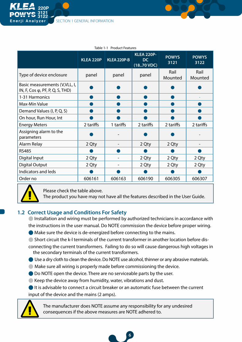
Table 1-1 Product Features
KLEA 220P KLEA 220P-BKLEA 220P-
DC(18..70 VDC)
POWYS 3121
POWYS 3122
Type of device enclosure panel panel panel Rail Mounted
Rail Mounted
Basic measurements (V,VLL, I, IN, F, Cos φ, PF, P, Q, S, THD)
1-31 Harmonics -
Max-Min Value
Demand Values (I, P, Q, S)
On hour, Run Hour, Int
Energy Meters 2 tariffs 1 tariffs 2 tariffs 2 tariffs 2 tariffsAssigning alarm to the parameters
- -
Alarm Relay 2 Qty - 2 Qty 2 Qty -RS485
Digital Input 2 Qty - 2 Qty 2 Qty 2 QtyDigital Output 2 Qty - 2 Qty 2 Qty 2 QtyIndicators and leds
Order no 606161 606163 606190 606305 606307
Please check the table above.The product you have may not have all the features described in the User Guide.
1.2 Correct Usage and Conditions For Safetyl Installation and wiring must be performed by authorized technicians in accordance withthe instructions in the user manual. Do NOTE commission the device before proper wiring.l Make sure the device is de-energized before connecting to the mains.l Short circuit the k-l terminals of the current transformer in another location before dis-connecting the current transformers. Failing to do so will cause dangerous high voltages in
the secondary terminals of the current transformers.l Use a dry cloth to clean the device. Do NOTE use alcohol, thinner or any abrasive materials.l Make sure all wiring is properly made before commissioning the device.l Do NOTE open the device. There are no serviceable parts by the user.l Keep the device away from humidity, water, vibrations and dust.l It is advisable to connect a circuit breaker or an automatic fuse between the currentinput of the device and the mains (2 amps).
The manufacturer does NOTE assume any responsibility for any undesiredconsequences if the above measures are NOTE adhered to.
SECTION 1 GENERAL INFORMATION
7
E n e r j i A n a l y z e r
31213122
1.3 Panel Definitions
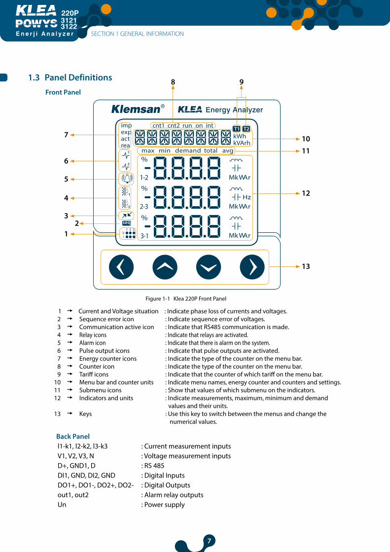
Figure 1-1 Klea 220P Front Panel
1 Current and Voltage situation : Indicate phase loss of currents and voltages.2 Sequence error icon : Indicate sequence error of voltages.3 Communication active icon : Indicate that RS485 communication is made.4 Relay icons : Indicate that relays are activated.5 Alarm icon : Indicate that there is alarm on the system. 6 Pulse output icons : Indicate that pulse outputs are activated.7 Energy counter icons : Indicate the type of the counter on the menu bar.8 Counter icon : Indicate the type of the counter on the menu bar.9 Tariff icons : Indicate that the counter of which tariff on the menu bar.
10 Menu bar and counter units : Indicate menu names, energy counter and counters and settings. 11 Submenu icons : Show that values of which submenu on the indicators.12 Indicators and units : Indicate measurements, maximum, minimum and demand
values and their units.13 Keys : Use this key to switch between the menus and change the
numerical values.
Back Panel l1-k1, l2-k2, l3-k3 : Current measurement inputs V1, V2, V3, N : Voltage measurement inputs D+, GND1, D : RS 485DI1, GND, DI2, GND : Digital Inputs DO1+, DO1-, DO2+, DO2- : Digital Outputs out1, out2 : Alarm relay outputsUn : Power supply
SECTION 1 GENERAL INFORMATION
Front Panel
10
11
12
13
12
3
4
5
6
7
8 9

8
E n e r j i A n a l y z e r
31213122
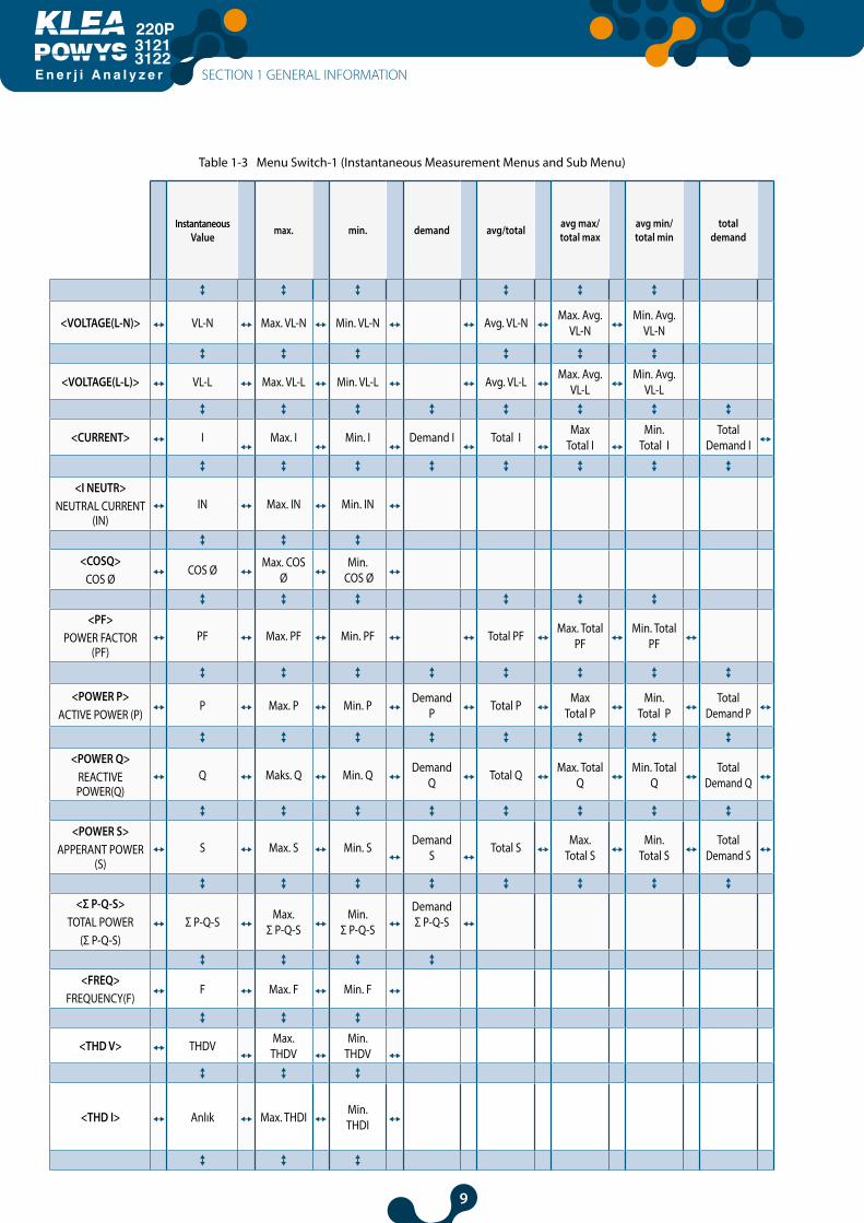
1.4 Menu StructureThe menus are shown instantaneous measurements menu and their maximum, minimum, demand, average and total value at the tables below. The menu pages change with up, down, right and left direction buttons.
1.4.1 Key FunctionsThe buttons placed front panel and their functions are explained at the table below.
Table 1-2 Key Functions
At the Measurements Menus
At the ENERGY, COUNTERS,
HARMONICS, SETTINGS Menus
Initialize the Counter To change the settings
Short
Pressing (t < 2sec)
Long Pressing (t > 2sec)
Short Pressing (t < 2sec)
Long Pressing (t > 2sec)
Long Pressing (t < 2sec)
Long Pressing (t > 2sec)
Short Pressing (t > 2sec)
Long Pressing (t > 2sec)
RIGHT BUTTON
Switching between
menus
Skips to “ENERGY”
menu
Pass to the one sub-
menu
Skips to bottom menu
Changes the active
step
Activates the value changing
Activates the value
changing orChanges
the active step
N/A
DOWN BUTTON
Switching between
menusN/A
Changes the menu
pageN/A değeri
değiştirir N/A Changes the value N/A
UP BUTTON
Switching between
menusN/A
Changes the menu
pageN/A Changes
the value N/A Changes the value N/A
LEFT BUTTON
Switching between
menus
Skips to Starting
Page
Pass to the one upper-
menu
Skip to the last menu
from
Stops changing value and confirms
the entering value
N/A
Stops changing value and confirms
the entering value
N/A
SECTION 1 GENERAL INFORMATION
9
E n e r j i A n a l y z e r
31213122
SECTION 1 GENERAL INFORMATION
Table 1-3 Menu Switch-1 (Instantaneous Measurement Menus and Sub Menu)
InstantaneousValue max. min. demand avg/total avg max/
total max avg min/total min total
demand
<VOLTAGE(L-N)> VL-N Max. VL-N Min. VL-N Avg. VL-N Max. Avg. VL-N
Min. Avg. VL-N
<VOLTAGE(L-L)> VL-L Max. VL-L Min. VL-L Avg. VL-L Max. Avg. VL-L
Min. Avg. VL-L
<CURRENT> I Max. I Min. I Demand I Total I Max Total I
Min. Total I Total
Demand I
<I NEUTR>NEUTRAL CURRENT
(IN)IN Max. IN Min. IN
<COSQ>COS Ø
COS Ø Max. COS Ø
Min. COS Ø
<PF>POWER FACTOR
(PF)PF Max. PF Min. PF Total PF Max. Total
PFMin. Total
PF
<POWER P>ACTIVE POWER (P)
P Max. P Min. P Demand P Total P Max
Total PMin.
Total PTotal
Demand P
<POWER Q>REACTIVE POWER(Q)
Q Maks. Q Min. Q Demand Q Total Q Max. Total
QMin. Total
QTotal
Demand Q
<POWER S>APPERANT POWER
(S)S Max. S Min. S Demand
S Total S Max.
Total SMin.
Total STotal
Demand S
<Σ P-Q-S>TOTAL POWER
(Σ P-Q-S)Σ P-Q-S Max.
Σ P-Q-SMin.
Σ P-Q-S
DemandΣ P-Q-S
<FREQ>FREQUENCY(F)
F Max. F Min. F
<THD V> THDV Max. THDV
Min. THDV
<THD I> Anlık Max. THDI Min. THDI
10
E n e r j i A n a l y z e r
31213122
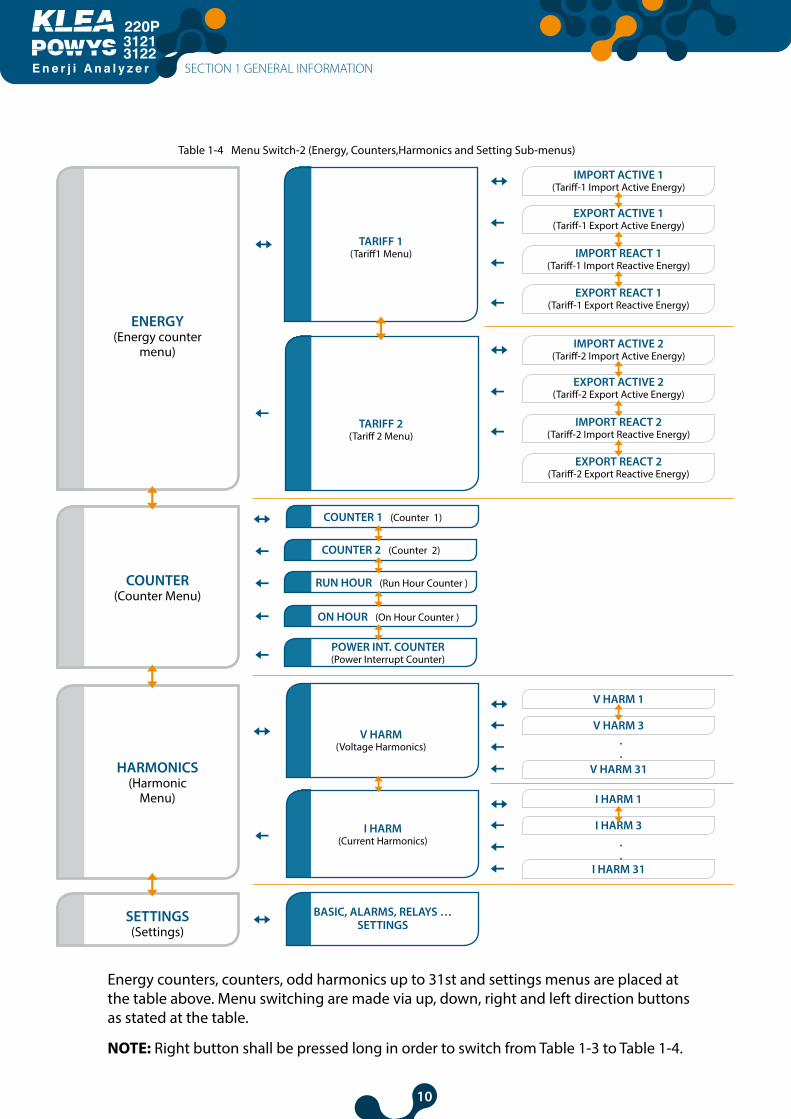
Table 1-4 Menu Switch-2 (Energy, Counters,Harmonics and Setting Sub-menus)
IMPORT ACTIVE 1(Tariff-1 Import Active Energy)
V HARM 1
I HARM 1
V HARM 3
I HARM 3
.
.
.
.
V HARM 31
I HARM 31
IMPORT ACTIVE 2(Tariff-2 Import Active Energy)
COUNTER 1 (Counter 1)
TARIFF 1 (Tariff1 Menu)
ENERGY (Energy counter
menu)
COUNTER (Counter Menu)
HARMONICS (Harmonic
Menu)
SETTINGS(Settings)
TARIFF 2 (Tariff 2 Menu)
V HARM(Voltage Harmonics)
I HARM(Current Harmonics)
BASIC, ALARMS, RELAYS … SETTINGS
EXPORT ACTIVE 1(Tariff-1 Export Active Energy)
EXPORT ACTIVE 2(Tariff-2 Export Active Energy)
COUNTER 2 (Counter 2)
IMPORT REACT 1(Tariff-1 Import Reactive Energy)
IMPORT REACT 2(Tariff-2 Import Reactive Energy)
RUN HOUR (Run Hour Counter )
EXPORT REACT 1(Tariff-1 Export Reactive Energy)
EXPORT REACT 2(Tariff-2 Export Reactive Energy)
ON HOUR (On Hour Counter )
POWER INT. COUNTER(Power Interrupt Counter)
Energy counters, counters, odd harmonics up to 31st and settings menus are placed at the table above. Menu switching are made via up, down, right and left direction buttons as stated at the table.
NOTE: Right button shall be pressed long in order to switch from Table 1-3 to Table 1-4.
SECTION 1 GENERAL INFORMATION
11
E n e r j i A n a l y z e r
31213122
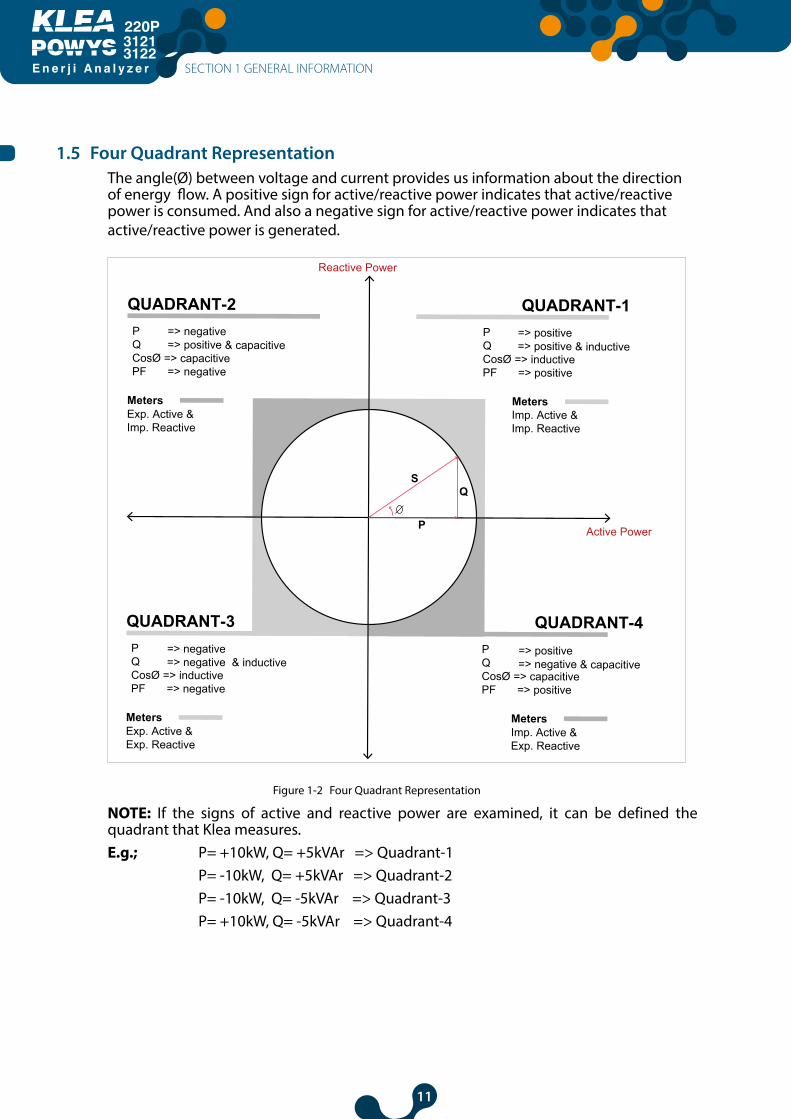
1.5 Four Quadrant RepresentationThe angle(Ø) between voltage and current provides us information about the direction of energy flow. A positive sign for active/reactive power indicates that active/reactive power is consumed. And also a negative sign for active/reactive power indicates that active/reactive power is generated.
Active Power
Reactive Power
MetersExp. Active & Imp. Reactive
QUADRANT-1P Q
=> positive=> positive & inductive
CosØ => inductivePF => positive
MetersImp. Active & Imp. Reactive
QUADRANT-2P Q
=> negative=> positive & capacitive
CosØ => capacitivePF => negative
MetersImp. Active & Exp. Reactive
MetersExp. Active &Exp. Reactive
QUADRANT-4P Q
=> positive=> negative & capacitive
CosØ => capacitivePF => positive
QUADRANT-3P Q
=> negative=> negative & inductive
CosØ => inductivePF => negative
S
P
Q
Figure 1-2 Four Quadrant Representation
NOTE: If the signs of active and reactive power are examined, it can be defined the quadrant that Klea measures. E.g.; P= +10kW, Q= +5kVAr => Quadrant-1 P= -10kW, Q= +5kVAr => Quadrant-2 P= -10kW, Q= -5kVAr => Quadrant-3 P= +10kW, Q= -5kVAr => Quadrant-4
SECTION 1 GENERAL INFORMATION

12
E n e r j i A n a l y z e r
31213122
SECTION 2INSTALLATION
EnergyAnalyzer
220P
3121-3122
13
E n e r j i A n a l y z e r
31213122
SECTION 2 INSTALLATION
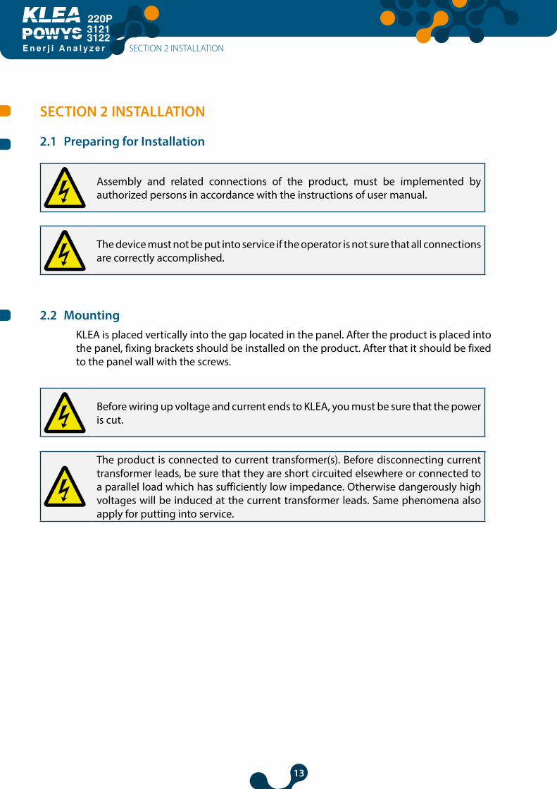
2.1 Preparing for Installation
Assembly and related connections of the product, must be implemented by authorized persons in accordance with the instructions of user manual.
The device must not be put into service if the operator is not sure that all connections are correctly accomplished.
2.2 MountingKLEA is placed vertically into the gap located in the panel. After the product is placed into the panel, fixing brackets should be installed on the product. After that it should be fixed to the panel wall with the screws.
Before wiring up voltage and current ends to KLEA, you must be sure that the power is cut.
The product is connected to current transformer(s). Before disconnecting current transformer leads, be sure that they are short circuited elsewhere or connected to a parallel load which has sufficiently low impedance. Otherwise dangerously high voltages will be induced at the current transformer leads. Same phenomena also apply for putting into service.
SECTION 2 INSTALLATION

14
E n e r j i A n a l y z e r
31213122
2.3 Connection Diagrams
2.3.1 3P-4W and 3p-3W ConnectionsThere are two ways for connections of voltage and current. With neutral (3P-4W), without neutral (3P-3W).
3P-4W (with neutral) 3P-3W (without neutral)
Figure 2-1 Connection Diagram
Figure 1-1 1st item, displays current and voltage phase position are On/Off. If a current or voltage phase seems incomplete and should be checked by the relevant links / connections reached the device.
Figure 1-1 2nd item, if there is an error in the voltage phase during due to incorrect sequence; "Voltage phase sequence error icon" will appear. If this icon appears; phase-sequence voltage should be checked.
SECTION 2 INSTALLATION
MeasuringCurrent
MeasuringCurrent
MeasuringVoltage
MeasuringVoltage
15
E n e r j i A n a l y z e r
31213122
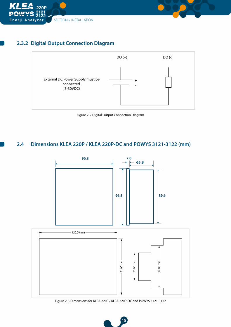
2.3.2 Digital Output Connection Diagram
External DC Power Supply must be connected.(5-30VDC)
DO (-)DO (+)
+-
Figure 2-2 Digital Output Connection Diagram
2.4 Dimensions KLEA 220P / KLEA 220P-DC and POWYS 3121-3122 (mm)
Figure 2-3 Dimensions for KLEA 220P / KLEA 220P-DC and POWYS 3121-3122
SECTION 2 INSTALLATION
65.8

16
E n e r j i A n a l y z e r
31213122
SECTION 3MENUS
EnergyAnalyzer
220P
3121-3122
17
E n e r j i A n a l y z e r
31213122
SECTION 3 MENUS
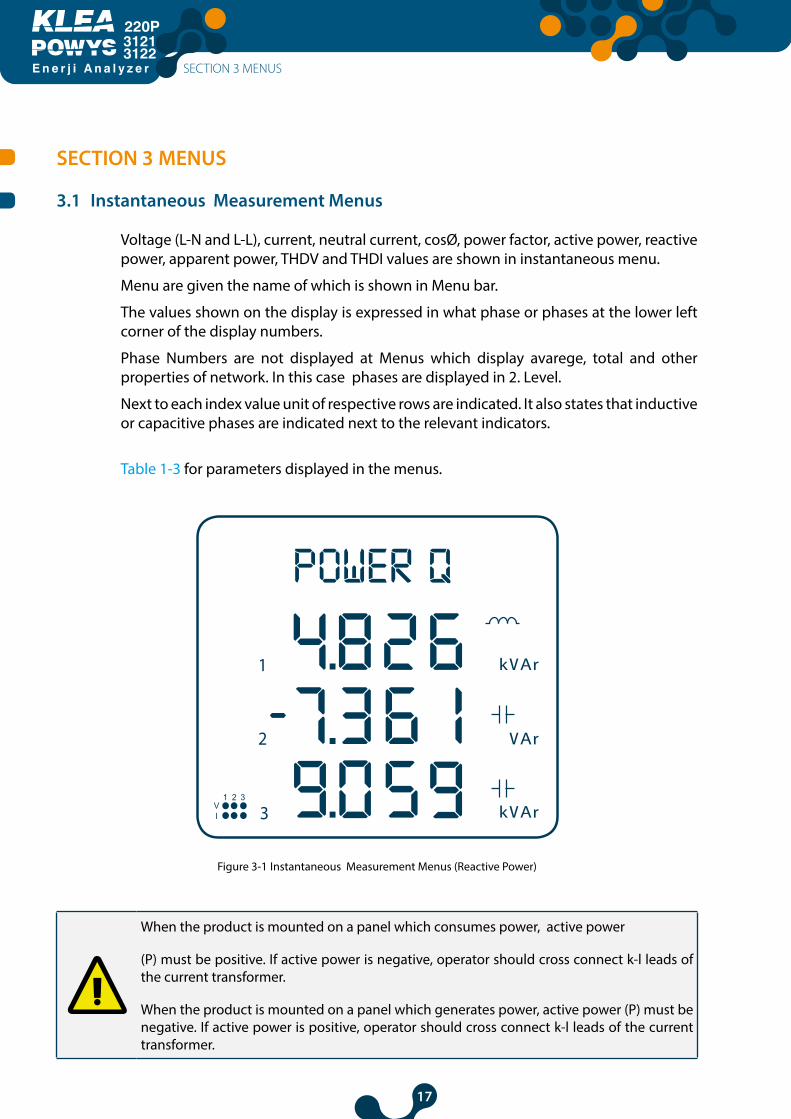
3.1 Instantaneous Measurement Menus
Voltage (L-N and L-L), current, neutral current, cosØ, power factor, active power, reactive power, apparent power, THDV and THDI values are shown in instantaneous menu.
Menu are given the name of which is shown in Menu bar.
The values shown on the display is expressed in what phase or phases at the lower left corner of the display numbers.
Phase Numbers are not displayed at Menus which display avarege, total and other properties of network. In this case phases are displayed in 2. Level.
Next to each index value unit of respective rows are indicated. It also states that inductive or capacitive phases are indicated next to the relevant indicators.
Table 1-3 for parameters displayed in the menus.
Figure 3-1 Instantaneous Measurement Menus (Reactive Power)
When the product is mounted on a panel which consumes power, active power
(P) must be positive. If active power is negative, operator should cross connect k-l leads of the current transformer.
When the product is mounted on a panel which generates power, active power (P) must be negative. If active power is positive, operator should cross connect k-l leads of the current transformer.
SECTION 3 MENUS
POWER Q
18
E n e r j i A n a l y z e r
31213122
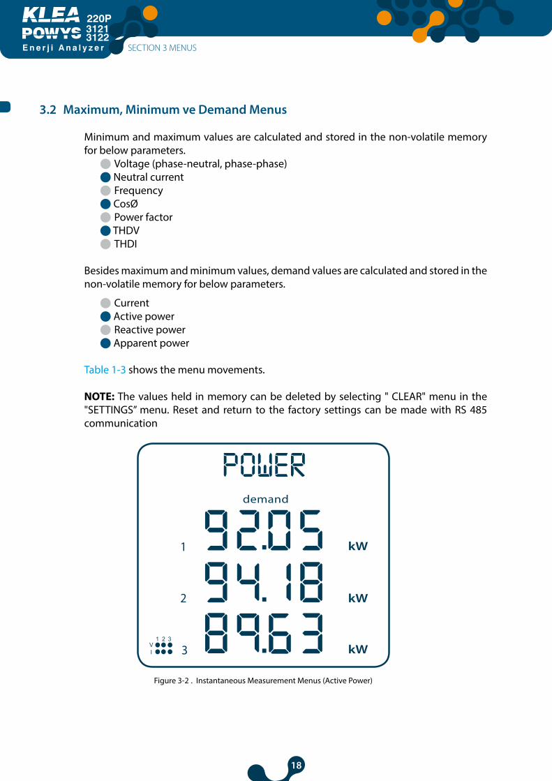
3.2 Maximum, Minimum ve Demand Menus
Minimum and maximum values are calculated and stored in the non-volatile memory for below parameters.
l Voltage (phase-neutral, phase-phase)l Neutral currentl Frequency l CosØ l Power factor l THDVl THDI
Besides maximum and minimum values, demand values are calculated and stored in the non-volatile memory for below parameters.
l Current l Active powerl Reactive powerl Apparent power
Table 1-3 shows the menu movements.
NOTE: The values held in memory can be deleted by selecting " CLEAR" menu in the "SETTINGS’’ menu. Reset and return to the factory settings can be made with RS 485 communication
Figure 3-2 . Instantaneous Measurement Menus (Active Power)
SECTION 3 MENUS
POWER
19
E n e r j i A n a l y z e r
31213122
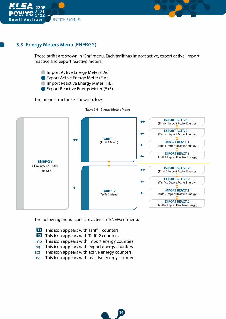
3.3 Energy Meters Menu (ENERGY)
These tariffs are shown in “Enr” menu. Each tariff has import active, export active, import reactive and export reactive meters.
l Import Active Energy Meter (I.Ac) l Export Active Energy Meter (E.Ac) l Import Reactive Energy Meter (I.rE) l Export Reactive Energy Meter (E.rE)
The menu structure is shown below:
Table 3-1 Energy Meters Menu
IMPORT ACTIVE 1(Tariff-1 Import Active Energy)
IMPORT ACTIVE 2(Tariff-2 Import Active Energy)
TARIFF 1 (Tariff 1 Menu)
ENERGY ( Energy counter
menu )
TARIFF 2 (Tarife 2 Menu)
EXPORT ACTIVE 1(Tariff-1 Export Active Energy)
EXPORT ACTIVE 2(Tariff-2 Export Active Energy)
IMPORT REACT 1(Tariff-1 Import Reactive Energy)
IMPORT REACT 2(Tariff-2 Import Reactive Energy)
EXPORT REACT 1(Tariff-1 Export Reactive Energy)
EXPORT REACT 2(Tariff-2 Export Reactive Energy)
The following menu icons are active in “ENERGY” menu:
: This icon appears with Tariff 1 counters : This icon appears with Tariff 2 countersimp : This icon appears with import energy countersexp : This icon appears with export energy counters act : This icon appears with active energy counters rea : This icon appears with reactive energy counters
SECTION 3 MENUS
20
E n e r j i A n a l y z e r
31213122
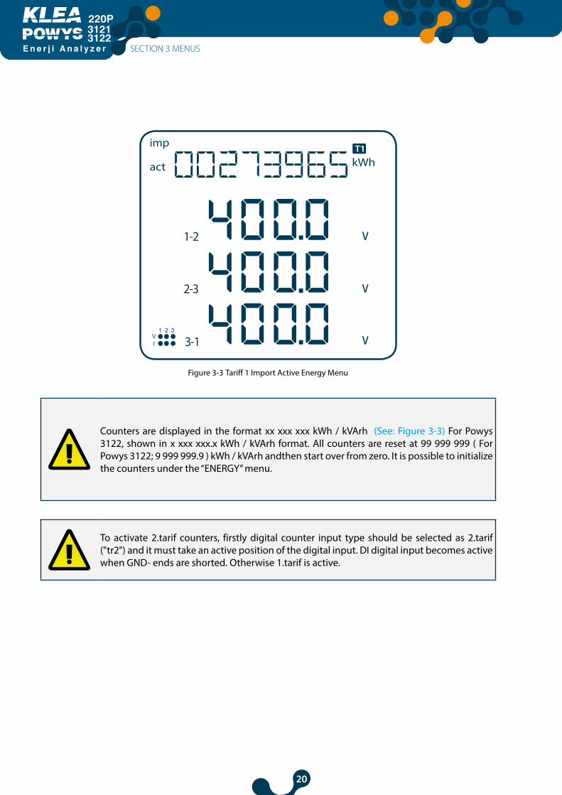
Figure 3-3 Tariff 1 Import Active Energy Menu
Counters are displayed in the format xx xxx xxx kWh / kVArh (See: Figure 3-3) For Powys 3122, shown in x xxx xxx.x kWh / kVArh format. All counters are reset at 99 999 999 ( For Powys 3122; 9 999 999.9 ) kWh / kVArh andthen start over from zero. It is possible to initialize the counters under the “ENERGY” menu.
To activate 2.tarif counters, firstly digital counter input type should be selected as 2.tarif ("tr2") and it must take an active position of the digital input. DI digital input becomes active when GND- ends are shorted. Otherwise 1.tarif is active.
SECTION 3 MENUS
21
E n e r j i A n a l y z e r
31213122
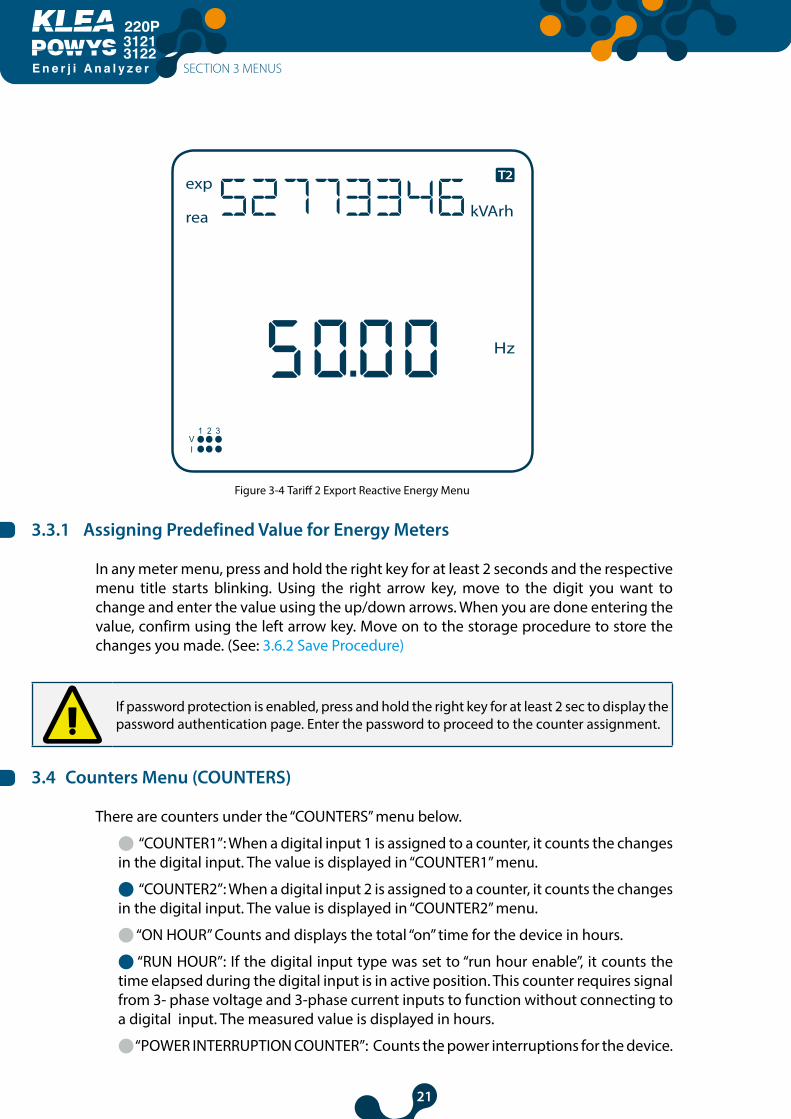
Figure 3-4 Tariff 2 Export Reactive Energy Menu
3.3.1 Assigning Predefined Value for Energy Meters
In any meter menu, press and hold the right key for at least 2 seconds and the respective menu title starts blinking. Using the right arrow key, move to the digit you want to change and enter the value using the up/down arrows. When you are done entering the value, confirm using the left arrow key. Move on to the storage procedure to store the changes you made. (See: 3.6.2 Save Procedure)
If password protection is enabled, press and hold the right key for at least 2 sec to display the password authentication page. Enter the password to proceed to the counter assignment.
3.4 Counters Menu (COUNTERS)
There are counters under the “COUNTERS” menu below.
l “COUNTER1”: When a digital input 1 is assigned to a counter, it counts the changes in the digital input. The value is displayed in “COUNTER1” menu.
l “COUNTER2”: When a digital input 2 is assigned to a counter, it counts the changes in the digital input. The value is displayed in “COUNTER2” menu.
l “ON HOUR” Counts and displays the total “on” time for the device in hours.
l “RUN HOUR”: If the digital input type was set to “run hour enable”, it counts the time elapsed during the digital input is in active position. This counter requires signal from 3- phase voltage and 3-phase current inputs to function without connecting to a digital input. The measured value is displayed in hours.
l “POWER INTERRUPTION COUNTER”: Counts the power interruptions for the device.
SECTION 3 MENUS
22
E n e r j i A n a l y z e r
31213122
“POWER INTERRUPTION COUNTER”: Counts the power interruptions for the device.
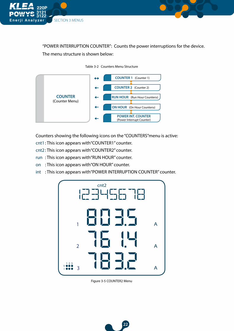
The menu structure is shown below:
Table 3-2 Counters Menu Structure
COUNTER 1 (Counter 1)
COUNTER (Counter Menu)
COUNTER 2 (Counter 2)
RUN HOUR (Run Hour Countersı)
ON HOUR (On Hour Countersı)
POWER INT. COUNTER(Power Interrupt Counter)
Counters showing the following icons on the “COUNTERS”menu is active:
cnt1 : This icon appears with“COUNTER1” counter.
cnt2 : This icon appears with“COUNTER2” counter.
run : This icon appears with“RUN HOUR” counter.
on : This icon appears with“ON HOUR” counter.
int : This icon appears with“POWER INTERRUPTION COUNTER” counter.
Figure 3-5 COUNTER2 Menu
SECTION 3 MENUS
23
E n e r j i A n a l y z e r
31213122
Counters are displayed as 8 digits. All counters are reset at 99 999 999 and then start over from zero.
Only “COUNTER1”, “COUNTER2” and “RUN HOUR” counters can be assigned values or reset. Use the procedure for assigning default values to assign values to counters.
See: 3.3.1 Save Procedure
When the energy meters are displayed instantaneously, last measured parameters (such as voltage, current, active power values etc.) are continued to display under the energy meter value as well.
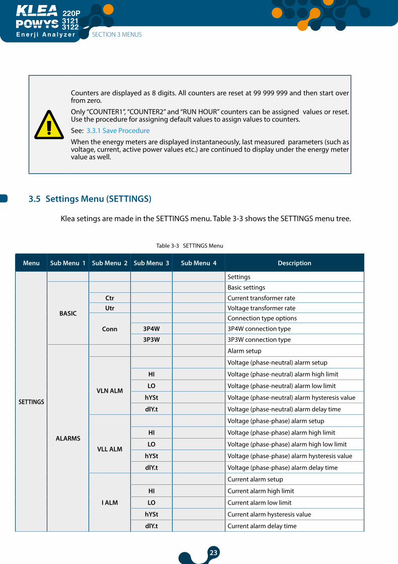
3.5 Settings Menu (SETTINGS)
Klea setings are made in the SETTINGS menu. Table 3-3 shows the SETTINGS menu tree.
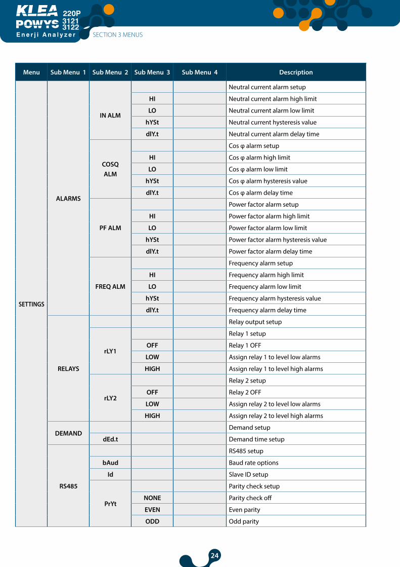
Table 3-3 SETTINGS Menu
Menu Sub Menu 1 Sub Menu 2 Sub Menu 3 Sub Menu 4 Description
SETTINGS
Settings
BASIC
Basic settings
Ctr Current transformer rateUtr Voltage transformer rate
Conn
Connection type options
3P4W 3P4W connection type
3P3W 3P3W connection type
ALARMS
Alarm setup
VLN ALM
Voltage (phase-neutral) alarm setup
HI Voltage (phase-neutral) alarm high limit
LO Voltage (phase-neutral) alarm low limit
hYSt Voltage (phase-neutral) alarm hysteresis value
dlY.t Voltage (phase-neutral) alarm delay time
VLL ALM
Voltage (phase-phase) alarm setup
HI Voltage (phase-phase) alarm high limit
LO Voltage (phase-phase) alarm high low limit
hYSt Voltage (phase-phase) alarm hysteresis value
dlY.t Voltage (phase-phase) alarm delay time
I ALM
Current alarm setup
HI Current alarm high limit
LO Current alarm low limit
hYSt Current alarm hysteresis value
dlY.t Current alarm delay time
SECTION 3 MENUS
24
E n e r j i A n a l y z e r
31213122
Menu Sub Menu 1 Sub Menu 2 Sub Menu 3 Sub Menu 4 Description
SETTINGS
ALARMS
IN ALM
Neutral current alarm setup
HI Neutral current alarm high limit
LO Neutral current alarm low limit
hYSt Neutral current hysteresis value
dlY.t Neutral current alarm delay time
COSQALM
Cos φ alarm setup
HI Cos φ alarm high limit
LO Cos φ alarm low limit
hYSt Cos φ alarm hysteresis value
dlY.t Cos φ alarm delay time
PF ALM
Power factor alarm setup
HI Power factor alarm high limit
LO Power factor alarm low limit
hYSt Power factor alarm hysteresis value
dlY.t Power factor alarm delay time
FREQ ALM
Frequency alarm setup
HI Frequency alarm high limit
LO Frequency alarm low limit
hYSt Frequency alarm hysteresis value
dlY.t Frequency alarm delay time
RELAYS
Relay output setup
rLY1
Relay 1 setup
OFF Relay 1 OFF
LOW Assign relay 1 to level low alarms
HIGH Assign relay 1 to level high alarms
rLY2
Relay 2 setup
OFF Relay 2 OFF
LOW Assign relay 2 to level low alarms
HIGH Assign relay 2 to level high alarms
DEMAND Demand setup
dEd.t Demand time setup
RS485
RS485 setup
bAud Baud rate options
Id Slave ID setup
PrYt
Parity check setup
NONE Parity check off
EVEN Even parity
ODD Odd parity
SECTION 3 MENUS

25
E n e r j i A n a l y z e r
31213122
Menu Sub Menu 1 Sub Menu 2 Sub Menu 3 Sub Menu 4 Description
SETTINGS
DI INPUT
Digital input setup
INPUT1
Digital input 1 setup
tYPE
Digital input 1 options
OFF Off
TARIFF 2 Enable tariff 2
COUNTER Enable counter
RUN HOUR Enable Run Hour
dLY Digital input 1 detection delay time
EdgE
Digital input 1 detection edge
RISING Detection in rising edge
FALLING Detection in falling edge (Only valid for counter)
BOTH EDG Detection in both edges (Only valid for counter)
INPUT2
Digital input 2 setup
tYPE
Digital input 2 options
OFF Off
TARIFF 2 Enable tariff 2
COUNTER Enable counter
RUN HOUR Enable Run Hour
dLY Digital input 2 detection delay time
EdgE
Digital input 2 detection edge
RISING Detection in rising edge
FALLING Detection in falling edge (Only valid for counter)
BOTH EDG Detection in both edges (Only valid for counter)
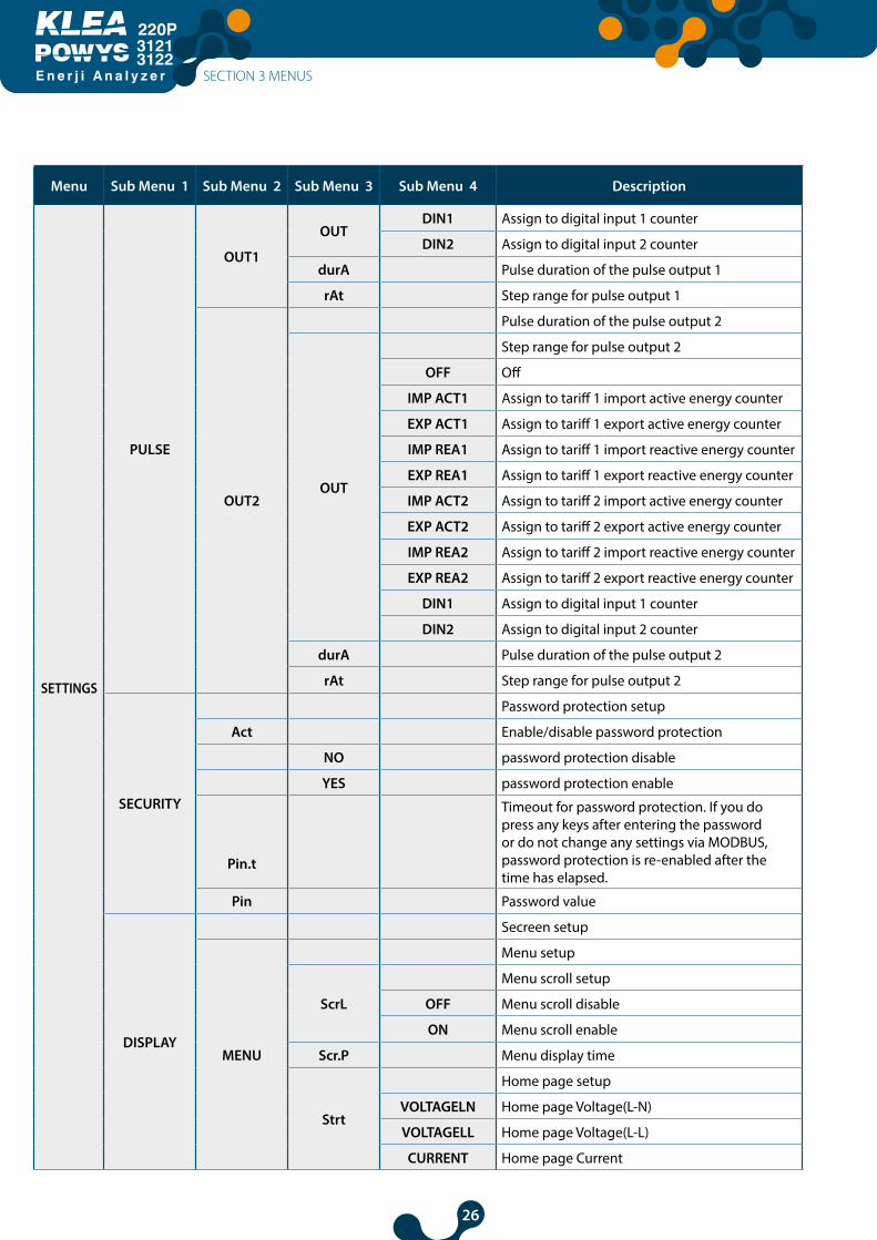
PULSE
Pulse output setup
OUT1
Pulse output 1 setup
OUT
Pulse output 1 parameter setup
OFF Off
IMP ACT1 Assign to tariff 1 import active energy counter
EXP ACT1 Assign to tariff 1 export active energy counter
IMP REA1 Assign to tariff 1 import reactive energy counter
EXP REA1 Assign to tariff 1 export reactive energy counter
IMP ACT2 Assign to tariff 2 import active energy counter
EXP ACT2 Assign to tariff 2 export active energy counter
IMP REA2 Assign to tariff 2 import reactive energy counter
EXP REA2 Assign to tariff 2 export reactive energy counter
SECTION 3 MENUS
26
E n e r j i A n a l y z e r
31213122
Menu Sub Menu 1 Sub Menu 2 Sub Menu 3 Sub Menu 4 Description
SETTINGS
PULSE
OUT1
OUTDIN1 Assign to digital input 1 counter
DIN2 Assign to digital input 2 counter
durA Pulse duration of the pulse output 1
rAt Step range for pulse output 1
OUT2
Pulse duration of the pulse output 2
OUT
Step range for pulse output 2
OFF Off
IMP ACT1 Assign to tariff 1 import active energy counter
EXP ACT1 Assign to tariff 1 export active energy counter
IMP REA1 Assign to tariff 1 import reactive energy counter
EXP REA1 Assign to tariff 1 export reactive energy counter
IMP ACT2 Assign to tariff 2 import active energy counter
EXP ACT2 Assign to tariff 2 export active energy counter
IMP REA2 Assign to tariff 2 import reactive energy counter
EXP REA2 Assign to tariff 2 export reactive energy counter
DIN1 Assign to digital input 1 counter
DIN2 Assign to digital input 2 counter
durA Pulse duration of the pulse output 2
rAt Step range for pulse output 2
SECURITY
Password protection setup
Act Enable/disable password protection
NO password protection disable
YES password protection enable
Pin.t
Timeout for password protection. If you do press any keys after entering the password or do not change any settings via MODBUS, password protection is re-enabled after the time has elapsed.
Pin Password value
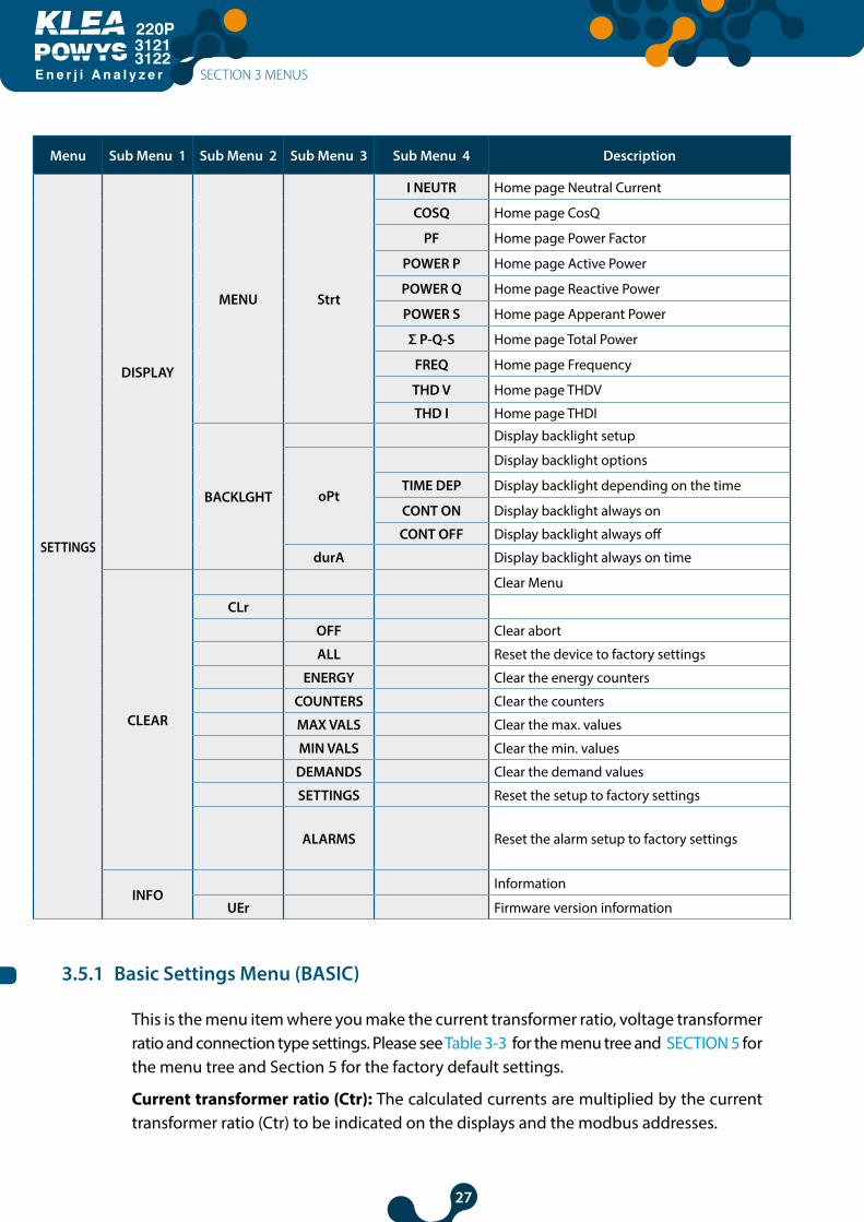
DISPLAY
Secreen setup
MENU
Menu setup
ScrL
Menu scroll setup
OFF Menu scroll disable
ON Menu scroll enable
Scr.P Menu display time
Strt
Home page setup
VOLTAGELN Home page Voltage(L-N)
VOLTAGELL Home page Voltage(L-L)
CURRENT Home page Current
SECTION 3 MENUS
27
E n e r j i A n a l y z e r
31213122
Menu Sub Menu 1 Sub Menu 2 Sub Menu 3 Sub Menu 4 Description
SETTINGS
DISPLAY
MENU Strt
I NEUTR Home page Neutral Current
COSQ Home page CosQ
PF Home page Power Factor
POWER P Home page Active Power
POWER Q Home page Reactive Power
POWER S Home page Apperant Power
Σ P-Q-S Home page Total Power
FREQ Home page Frequency
THD V Home page THDV
THD I Home page THDI
BACKLGHT
Display backlight setup
oPt
Display backlight options
TIME DEP Display backlight depending on the time
CONT ON Display backlight always on
CONT OFF Display backlight always off
durA Display backlight always on time
CLEAR
Clear Menu
CLr
OFF Clear abort
ALL Reset the device to factory settings
ENERGY Clear the energy counters
COUNTERS Clear the counters
MAX VALS Clear the max. values
MIN VALS Clear the min. values
DEMANDS Clear the demand values
SETTINGS Reset the setup to factory settings
ALARMS Reset the alarm setup to factory settings
INFOInformation
UEr Firmware version information
3.5.1 Basic Settings Menu (BASIC)
This is the menu item where you make the current transformer ratio, voltage transformer ratio and connection type settings. Please see Table 3-3 for the menu tree and SECTION 5 for the menu tree and Section 5 for the factory default settings.
Current transformer ratio (Ctr): The calculated currents are multiplied by the current transformer ratio (Ctr) to be indicated on the displays and the modbus addresses.
SECTION 3 MENUS
28
E n e r j i A n a l y z e r
31213122
Voltage transformer ratio (Utr): The calculated voltages are multiplied by the voltage transformer ratio (Utr) to be indicated on the displays and the modbus addresses.
Connection (Conn): This menu is for the network connection settings.
If “3P4W” (3-phase, 4-wire connection type) was specified for the network connection setup, the initial menu is “Voltage (Phase-Neutral)”. This menu is displayed first when the device is energized.
If “3P3W” (3-phase, 3-wire connection type) was specified for the network connection setup, the initial menu is “Voltage (Phase-Phase)”. This menu is displayed first when the device is energized.
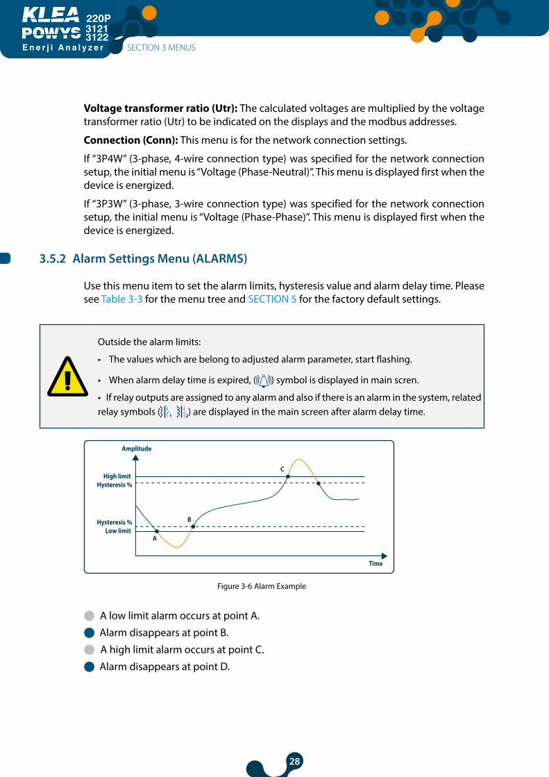
3.5.2 Alarm Settings Menu (ALARMS)
Use this menu item to set the alarm limits, hysteresis value and alarm delay time. Please see Table 3-3 for the menu tree and SECTION 5 for the factory default settings.
Outside the alarm limits:
• The values which are belong to adjusted alarm parameter, start flashing.
• When alarm delay time is expired, ( ) symbol is displayed in main scren.
• If relay outputs are assigned to any alarm and also if there is an alarm in the system, related relay symbols ( ) are displayed in the main screen after alarm delay time.
Amplitude
High limit Hysteresis %
Hysteresis %Low limit
Time
C
B
A
Figure 3-6 Alarm Example
l A low limit alarm occurs at point A.
l Alarm disappears at point B.
l A high limit alarm occurs at point C.
l Alarm disappears at point D.
SECTION 3 MENUS
29
E n e r j i A n a l y z e r
31213122
3.5.3 Alarm Relay Settings Menu (RELAYS)
Use this menu item to set the conditions of the alarm relays. You can set both alarm relays to the following positions:l OFF : Relay does not energize in an alarm condition.l LO : Relay energizes when a low limit alarm occurs.l HI : Relay energizes when a high limit alarm occurs.
Related relay is de-energized when the alarm condition ends. Please see Table 3-3 for the menu tree and SECTION 5 for the factory default settings
3.5.4 Demand Period Setting Menu (DEMAND)
Use this menu item to setup the demand period. At the end of the specified period,
demand values are calculated in a periodic cycle.
Please see Table 3-3 for the menu tree and SECTION 5 for the factory default settings.
3.5.5 RS485 Settings Menu (RS485)
Use this menu item to set the baudrate, slave ID and parity control settings in RS485 communication. Please see Table 3-3 for the menu tree and SECTION 5 for the factory default settings.
Baudrate (bAud): Communication Signal speed is expressed with "baud" in terms of units. The baud rate can be changed in the adjustment range.
Slave ID (Id): RS485 communication is working on the basis of one or more slave devices communicate with one master. KLEA, as a slave in the RS485 communication responds to queries made by the master. If the device is slave match in this communication are set in the slave ID Menu.
Parity Check (PrtY): It is a control mechanism for data accuracy. It counts odds ‘’1’’ in Binary data. There are ‘’odd’’and ‘even’’ parity control method.For communication, master and slave devices must be using the same method.The desired method is selected from the menu or " NONE" option selected to make parity check feature turned off.
SECTION 3 MENUS
30
E n e r j i A n a l y z e r
31213122
3.5.6 Digital Input Settings Menu (DI INPUT)
Use this menu item to set the on/off position, type, delay time and detection edge for the digital input. Please see Table 3-3 for the menu tree and SECTION 5 for the factory default settings.
Digital input is based on dry contact detection principle. Never apply signal to inputs. Otherwise there is risk of damaging the device.
Digital input type (tYPE):
l Option to enable tariff 2 (TARIFF 2): If you choose this option for the digital input type, tariff2 energy counters will be enabled when the digital input is active (dry contact must be applied from related DIN+ and DIN-).
l Option to enable the counter (COUNTER): If you choose this option for the digital input type, the counter will count the changes in the position of the digital input depending on the chosen detection edge.
m If you choose rising edge detection (RISING) for the detection edge, the counter will increase by 1 on each activation of the dry contact that is connected to the digital input.
m If you choose falling edge detection (FALLING) for the detection edge, the counter will increase by 1 on each de-activation of the dry contact that is connected to the digital input.
m If you choose both edges detection (BOTH EDGE) for the detection edge, the counter will increase by 1 on each activation and de-activaton of the dry contact that is connected to the digital input.
l Run Hour enable option (RUN HOUR): If you choose this option for the digital input type, the “run hour counter” start counting when the digital input is active.(Dry contact must be applied from related DIN+ and DIN-).
Detection delay time (dLY):
The input is enabled or disabled based on the detection delay time which is set to account for contact spikes or noise in the digital input.
Detection edge (EdgE):
Use this menu item to choose the position where the digital input is detected active or passive. This menu is available only for the digital input mode “counter”. Other options always use the rising edge detection.
SECTION 3 MENUS
31
E n e r j i A n a l y z e r
31213122
3.5.7 Pulse Output Settings Menu (PULSE)Use this menu item to specify the on/off position, output parameter, pulse duration and step range settings for the pulse outputs. You can freely choose the settings for each pulse output independent of each other. Please see Table 3-3 for the menu tree and SECTION 5 for the factory default settings.
The pulse output is activated with an increase in the predefined output parameter that is equal to each step range and deactivates after the predefined time.
Output parameter setup (OUT):
Use this menu item to set the parameter dependency of the output. The respective output is closed when you choose “OFF”.
Pulse duration setup (durA):
Use this menu item to specify the time the pulse is active.
Pulse step range (rAt):
Use this menu to specify the smallest possible increase for the input parameter that will output a pulse.
3.5.8 Password Settings Menu (SECURITY)Use this menu item to turn the password protection on/off, set a password activation time and change password settings editing options. Please see Table 3-3 for the menu tree and SECTION 5 for the factory default settings.
4 digit password protects the product setup and counter menus against unauthorized access and modifications. When activated, a password query screen is displayed if someone attempts to change the values. After a successful login, the device will not ask for a password until the “password activation time” has elapsed. You can set this value in the respective menu item. Please see Table 3-3 for the menu tree and SECTION 5 for the factory default settings.
If you do not press any keys after entering the password or do not change the settings via MODBUS, password protection is re-enabled after the password activation time has elapsed.
3.5.9 Display Setup (DISPLAY)The settings about menu screen and backlight are made in this menu.
Menu Setup (MENU):
Menu scroll setting, display time and start page are made in this sub-menu.
l Menu scroll setup (ScrL): Menu Navigation is given as a name to command which is moving menu screen to next one at the end of display time. If ‘’ON " is selected, Menu navigation is activated after device start or 15 seconds after the last key is pressed.
l Menu display period (Scr.P): Each menu appears in the screen during the period that is adjusted in “menu display time”. The unit is second and it is effective when menu scroll mode is “on”. It is ineffective when menu scroll mode is “off”.
SECTION 3 MENUS
32
E n e r j i A n a l y z e r
31213122
l Home page setup (Strt): When the device is first energized, first screen menu is called Menu opening page. Any of this menu can be set from available instantaneous measurements Menu as Home page. Pre value "VOLTAGELN" menu is designated as Home page.
Display Backlight Setup (BACKLGHT)
Is subhead which lets adjustment of display backlight options and duration of backlight.
l Display backlight options (oPt): This menu is adjustment of display backlight activation depending on the time (TIME DEP), always on (CONT ON) or permanently closed (CONT OFF).
Time Dependent (TIME DEP): Backlight is turned on with device operates or with a pressing any key. Display backlight will be turned off if there is no pressing any key after set time. It is preferred to have longer-lasting power -saving and LED lighting.
m Continuous ON (CONT ON): Display backlight stays on permanently.
m Continuous OFF (CONT OFF): Display backlight is permanently closed.
m Display Backlight On Time (durA): Menu is where screen backlight time period is set with unit of second.
l Display Backlight On Time (durA): Menu is where screen backlight time period is set with unit of second.
3.5.10 Clear Menu (CLEAR)Use this menu to delete the stored values in the memory and restore the factory settings. Please see Table 3-3 for the menu tree and SECTION 5 for the factory default settings.
The following options are available in the clear menu:
• OF : Disables the clear process.
• ALL : Clears all values stored in the memory and restores them to the default factory settings.
• ENERGY : Resets all energy counters.
• COUNTERS : Resets all counters.
• MAX VALS : Clears the maximum values stored in the memory.
• MIN VALS : Clears the minimum values stored in the memory.
• DEMAND : Clears the demand values stored in the memory.
• SETTINGS : Restores all settings to the factory settings
• ALARMS : Restores the alarm settings to the factory settings.
SECTION 3 MENUS
33
E n e r j i A n a l y z e r
31213122
In order to prevent an accidental deletion, “nO” / “YES” prompt is displayed if you choose any option other than “OFF” 3.6.3 Approval Prosedure
• To confirm the action:
Press the right key to blink the “NO” sign. Use the up/down keys to change the “NO” to “YES”. Then, press the left key to confirm the action.
• To discard the action:
Press the right key to blink the “NO” sign. Then, press the left key to confirm the “NO” option and exit the menu without making any deletions.
The device restarts if you choose SETINGS, ALARM or All and confirm the action. It will not restart if you choose other options. It will clear the values and returns back to the CLEAR menu.
3.6 Save, Changing Value and Approval Prosedure
3.6.1 Changing Value/Setting
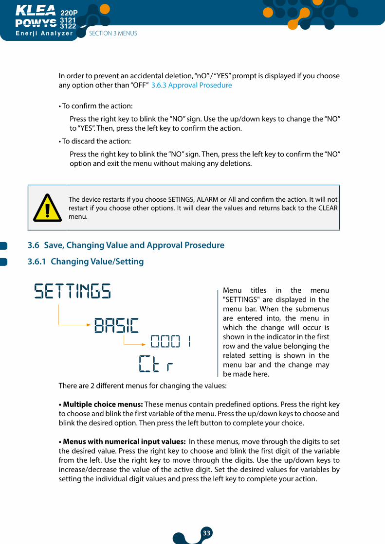
Menu titles in the menu "SETTINGS" are displayed in the menu bar. When the submenus are entered into, the menu in which the change will occur is shown in the indicator in the first row and the value belonging the related setting is shown in the menu bar and the change may be made here.
There are 2 different menus for changing the values:
• Multiple choice menus: These menus contain predefined options. Press the right key to choose and blink the first variable of the menu. Press the up/down keys to choose and blink the desired option. Then press the left button to complete your choice.
• Menus with numerical input values: In these menus, move through the digits to set the desired value. Press the right key to choose and blink the first digit of the variable from the left. Use the right key to move through the digits. Use the up/down keys to increase/decrease the value of the active digit. Set the desired values for variables by setting the individual digit values and press the left key to complete your action.
SECTION 3 MENUS
BASIC
SETTINGS

34
E n e r j i A n a l y z e r
31213122
If any change is made on settings, a registration procedure which is questioning whether or not to record the change will be active after return to " settings" menu. If the changes are saved, device restarts. See: 3.6.2 Save Prosedure
3.6.2 Save Prosedure
Press the left key until you see the “SAUE” display to confirm or discard the changes you made.
To confirm the changes:
Press the right key to blinkthe “NO” sign. Use the up/down keys to change the “NO” to “YES”. Then, press the left key to store the changes.
Değişiklikler reddedilecekse:
Press the right key to blink the “NO” sign. Then exit the menu using the left key without saving your changes.
SECTION 3 MENUS
YES
NO
SAVE
SAVE
35
E n e r j i A n a l y z e r
31213122
3.6.3 Approval Procedure
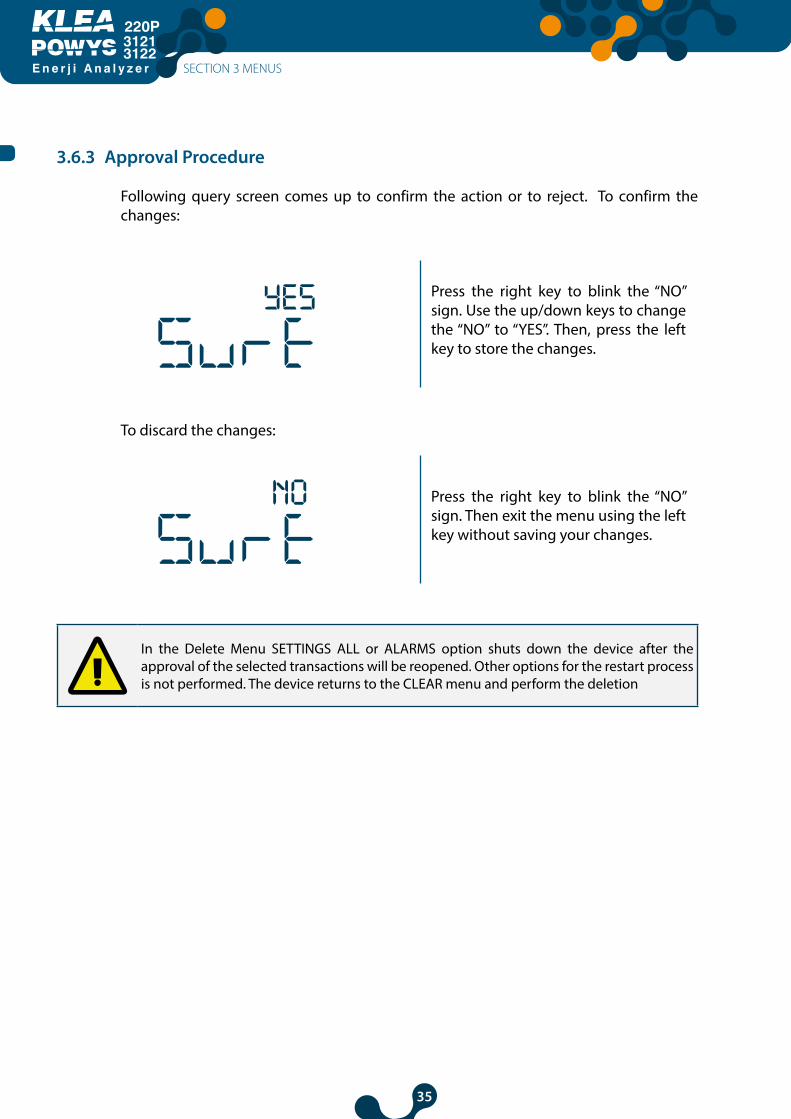
Following query screen comes up to confirm the action or to reject. To confirm the changes:
Press the right key to blink the “NO” sign. Use the up/down keys to change the “NO” to “YES”. Then, press the left key to store the changes.
To discard the changes:
Press the right key to blink the “NO” sign. Then exit the menu using the left key without saving your changes.
In the Delete Menu SETTINGS ALL or ALARMS option shuts down the device after the approval of the selected transactions will be reopened. Other options for the restart process is not performed. The device returns to the CLEAR menu and perform the deletion
SECTION 3 MENUS
YES
NO

36
E n e r j i A n a l y z e r
31213122
SECTION 4RS485
COMMUNICATION
EnergyAnalyzer
220P
3121-3122
37
E n e r j i A n a l y z e r
31213122
SECTION 4 RS485 COMMUNICATION
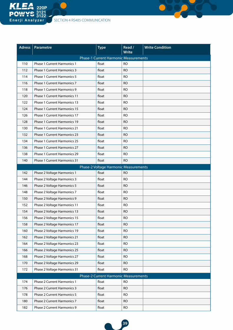
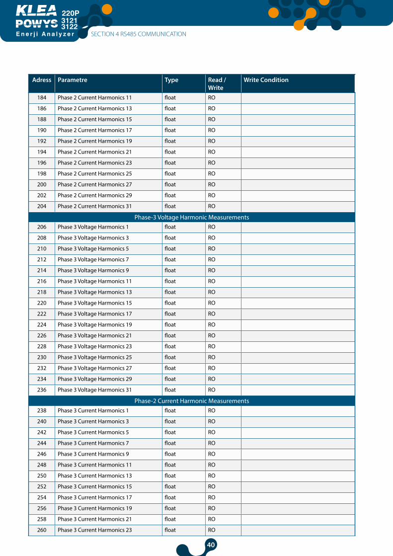
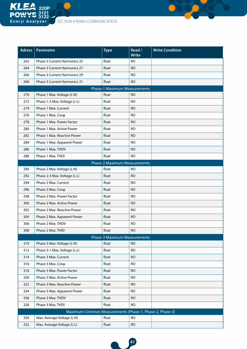
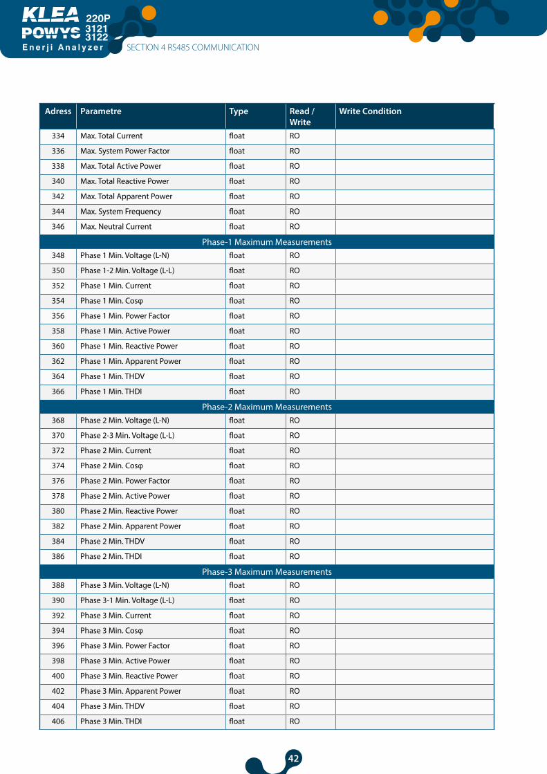
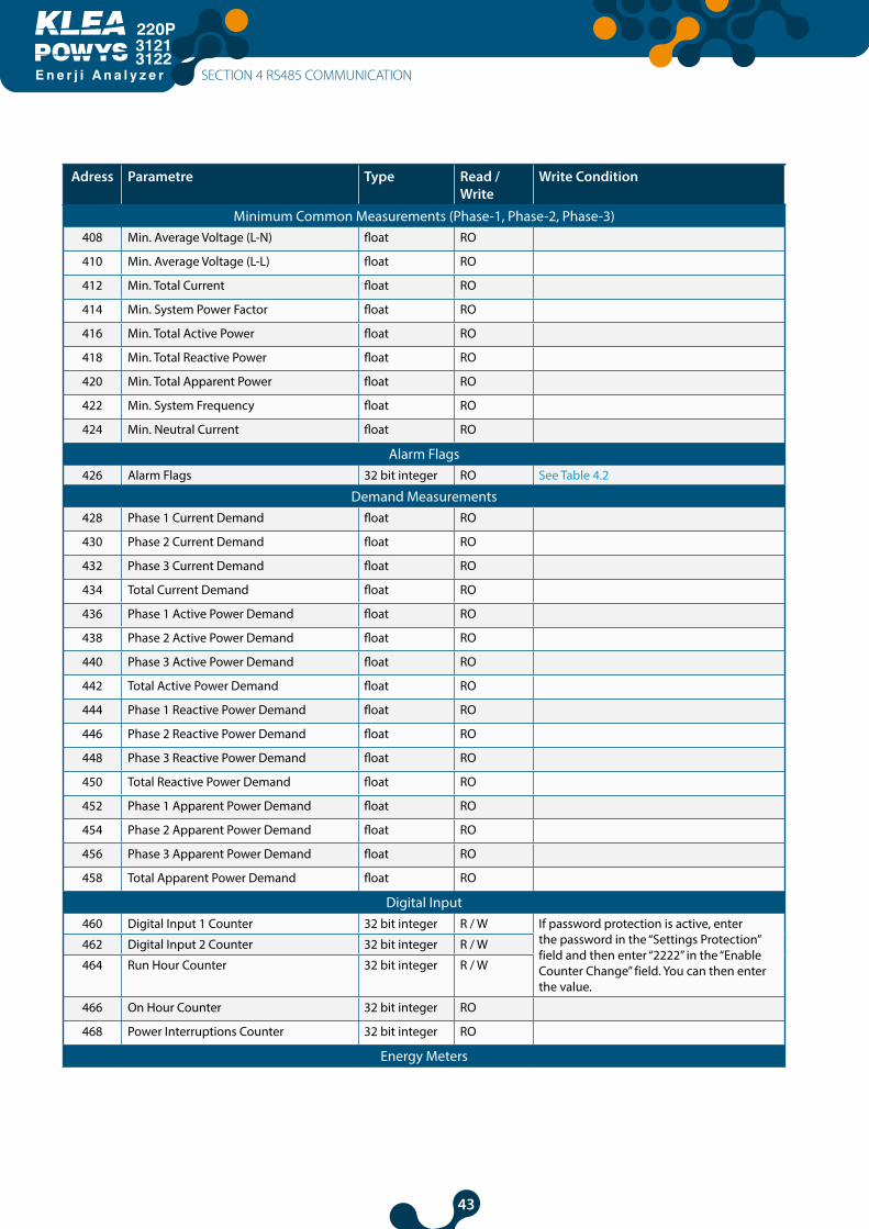
4.1 Readable and Writable Data
The following functions are supported:
• Function 03H: This function reads the readable addresses in the modbus table.• Function 10H: This function writes to the writable addresses in the modbus table.
Specifications:• R / W : Can read and write the value in this address.• RO : Can only read the value in this address.• WO : Can only write to this address• float : 32 bit floating number.
Related modbus table is given below: NOTE: The counter readings for POWYS 3122 are calculated by dividing by 100.
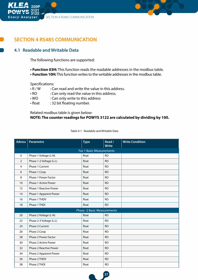
Table 4-1 Readable and Writable Data
Adress Parametre Type Read / Write
Write Condition
Faz 1 Basic Measurements0 Phase 1 Voltage (L-N) float RO
2 Phase 1-2 Voltage (L-L) float RO
4 Phase 1 Current float RO
6 Phase 1 Cosφ float RO
8 Phase 1 Power Factor float RO
10 Phase 1 Active Power float RO
12 Phase 1 Reactive Power float RO
14 Phase 1 Apparent Power float RO
16 Phase 1 THDV float RO
18 Phase 1 THDI float RO
Phase -2 Basic Measurements20 Phase 2 Voltage (L-N) float RO
22 Phase 2-3 Voltage (L-L) float RO
24 Phase 2 Current float RO
26 Phase 2 Cosφ float RO
28 Phase 2 Power Factor float RO
30 Phase 2 Active Power float RO
32 Phase 2 Reactive Power float RO
34 Phase 2 Apparent Power float RO
36 Phase 2 THDV float RO
38 Phase 2 THDI float RO
SECTION 4 RS485 COMMUNICATION
38
E n e r j i A n a l y z e r
31213122
Adress Parametre Type Read / Write
Write Condition
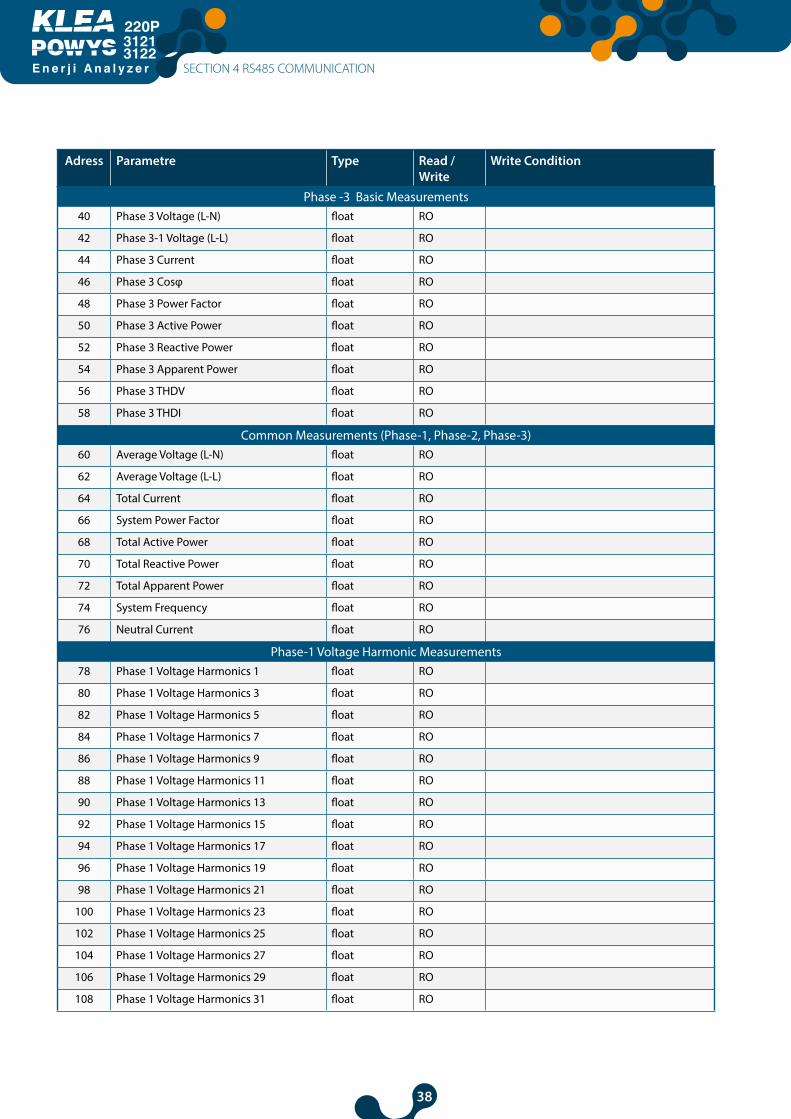
Phase -3 Basic Measurements40 Phase 3 Voltage (L-N) float RO
42 Phase 3-1 Voltage (L-L) float RO
44 Phase 3 Current float RO
46 Phase 3 Cosφ float RO
48 Phase 3 Power Factor float RO
50 Phase 3 Active Power float RO
52 Phase 3 Reactive Power float RO
54 Phase 3 Apparent Power float RO
56 Phase 3 THDV float RO
58 Phase 3 THDI float RO
Common Measurements (Phase-1, Phase-2, Phase-3)60 Average Voltage (L-N) float RO
62 Average Voltage (L-L) float RO
64 Total Current float RO
66 System Power Factor float RO
68 Total Active Power float RO
70 Total Reactive Power float RO
72 Total Apparent Power float RO
74 System Frequency float RO
76 Neutral Current float RO
Phase-1 Voltage Harmonic Measurements78 Phase 1 Voltage Harmonics 1 float RO
80 Phase 1 Voltage Harmonics 3 float RO
82 Phase 1 Voltage Harmonics 5 float RO
84 Phase 1 Voltage Harmonics 7 float RO
86 Phase 1 Voltage Harmonics 9 float RO
88 Phase 1 Voltage Harmonics 11 float RO
90 Phase 1 Voltage Harmonics 13 float RO
92 Phase 1 Voltage Harmonics 15 float RO
94 Phase 1 Voltage Harmonics 17 float RO
96 Phase 1 Voltage Harmonics 19 float RO
98 Phase 1 Voltage Harmonics 21 float RO
100 Phase 1 Voltage Harmonics 23 float RO
102 Phase 1 Voltage Harmonics 25 float RO
104 Phase 1 Voltage Harmonics 27 float RO
106 Phase 1 Voltage Harmonics 29 float RO
108 Phase 1 Voltage Harmonics 31 float RO
SECTION 4 RS485 COMMUNICATION
39
E n e r j i A n a l y z e r
31213122
Adress Parametre Type Read / Write
Write Condition
Phase-1 Current Harmonic Measurements110 Phase 1 Current Harmonics 1 float RO
112 Phase 1 Current Harmonics 3 float RO
114 Phase 1 Current Harmonics 5 float RO
116 Phase 1 Current Harmonics 7 float RO
118 Phase 1 Current Harmonics 9 float RO
120 Phase 1 Current Harmonics 11 float RO
122 Phase 1 Current Harmonics 13 float RO
124 Phase 1 Current Harmonics 15 float RO
126 Phase 1 Current Harmonics 17 float RO
128 Phase 1 Current Harmonics 19 float RO
130 Phase 1 Current Harmonics 21 float RO
132 Phase 1 Current Harmonics 23 float RO
134 Phase 1 Current Harmonics 25 float RO
136 Phase 1 Current Harmonics 27 float RO
138 Phase 1 Current Harmonics 29 float RO
140 Phase 1 Current Harmonics 31 float RO
Phase-2 Voltage Harmonic Measurements142 Phase 2 Voltage Harmonics 1 float RO
144 Phase 2 Voltage Harmonics 3 float RO
146 Phase 2 Voltage Harmonics 5 float RO
148 Phase 2 Voltage Harmonics 7 float RO
150 Phase 2 Voltage Harmonics 9 float RO
152 Phase 2 Voltage Harmonics 11 float RO
154 Phase 2 Voltage Harmonics 13 float RO
156 Phase 2 Voltage Harmonics 15 float RO
158 Phase 2 Voltage Harmonics 17 float RO
160 Phase 2 Voltage Harmonics 19 float RO
162 Phase 2 Voltage Harmonics 21 float RO
164 Phase 2 Voltage Harmonics 23 float RO
166 Phase 2 Voltage Harmonics 25 float RO
168 Phase 2 Voltage Harmonics 27 float RO
170 Phase 2 Voltage Harmonics 29 float RO
172 Phase 2 Voltage Harmonics 31 float RO
Phase-2 Current Harmonic Measurements174 Phase 2 Current Harmonics 1 float RO
176 Phase 2 Current Harmonics 3 float RO
178 Phase 2 Current Harmonics 5 float RO
180 Phase 2 Current Harmonics 7 float RO
182 Phase 2 Current Harmonics 9 float RO
SECTION 4 RS485 COMMUNICATION
40
E n e r j i A n a l y z e r
31213122
Adress Parametre Type Read / Write
Write Condition
184 Phase 2 Current Harmonics 11 float RO
186 Phase 2 Current Harmonics 13 float RO
188 Phase 2 Current Harmonics 15 float RO
190 Phase 2 Current Harmonics 17 float RO
192 Phase 2 Current Harmonics 19 float RO
194 Phase 2 Current Harmonics 21 float RO
196 Phase 2 Current Harmonics 23 float RO
198 Phase 2 Current Harmonics 25 float RO
200 Phase 2 Current Harmonics 27 float RO
202 Phase 2 Current Harmonics 29 float RO
204 Phase 2 Current Harmonics 31 float RO
Phase-3 Voltage Harmonic Measurements206 Phase 3 Voltage Harmonics 1 float RO
208 Phase 3 Voltage Harmonics 3 float RO
210 Phase 3 Voltage Harmonics 5 float RO
212 Phase 3 Voltage Harmonics 7 float RO
214 Phase 3 Voltage Harmonics 9 float RO
216 Phase 3 Voltage Harmonics 11 float RO
218 Phase 3 Voltage Harmonics 13 float RO
220 Phase 3 Voltage Harmonics 15 float RO
222 Phase 3 Voltage Harmonics 17 float RO
224 Phase 3 Voltage Harmonics 19 float RO
226 Phase 3 Voltage Harmonics 21 float RO
228 Phase 3 Voltage Harmonics 23 float RO
230 Phase 3 Voltage Harmonics 25 float RO
232 Phase 3 Voltage Harmonics 27 float RO
234 Phase 3 Voltage Harmonics 29 float RO
236 Phase 3 Voltage Harmonics 31 float RO
Phase-2 Current Harmonic Measurements238 Phase 3 Current Harmonics 1 float RO
240 Phase 3 Current Harmonics 3 float RO
242 Phase 3 Current Harmonics 5 float RO
244 Phase 3 Current Harmonics 7 float RO
246 Phase 3 Current Harmonics 9 float RO
248 Phase 3 Current Harmonics 11 float RO
250 Phase 3 Current Harmonics 13 float RO
252 Phase 3 Current Harmonics 15 float RO
254 Phase 3 Current Harmonics 17 float RO
256 Phase 3 Current Harmonics 19 float RO
258 Phase 3 Current Harmonics 21 float RO
260 Phase 3 Current Harmonics 23 float RO
SECTION 4 RS485 COMMUNICATION
41
E n e r j i A n a l y z e r
31213122
Adress Parametre Type Read / Write
Write Condition
262 Phase 3 Current Harmonics 25 float RO
264 Phase 3 Current Harmonics 27 float RO
266 Phase 3 Current Harmonics 29 float RO
268 Phase 3 Current Harmonics 31 float RO
Phase-1 Maximum Measurements270 Phase 1 Max. Voltage (L-N) float RO
272 Phase 1-2 Max. Voltage (L-L) float RO
274 Phase 1 Max. Current float RO
276 Phase 1 Max. Cosφ float RO
278 Phase 1 Max. Power Factor float RO
280 Phase 1 Max. Active Power float RO
282 Phase 1 Max. Reactive Power float RO
284 Phase 1 Max. Apparent Power float RO
286 Phase 1 Max. THDV float RO
288 Phase 1 Max. THDI float RO
Phase-2 Maximum Measurements290 Phase 2 Max. Voltage (L-N) float RO
292 Phase 2-3 Max. Voltage (L-L) float RO
294 Phase 2 Max. Current float RO
296 Phase 2 Max. Cosφ float RO
298 Phase 2 Max. Power Factor float RO
300 Phase 2 Max. Active Power float RO
302 Phase 2 Max. Reactive Power float RO
304 Phase 2 Max. Apparent Power float RO
306 Phase 2 Max. THDV float RO
308 Phase 2 Max. THDI float RO
Phase-3 Maximum Measurements310 Phase 3 Max. Voltage (L-N) float RO
312 Phase 3-1 Max. Voltage (L-L) float RO
314 Phase 3 Max. Current float RO
316 Phase 3 Max. Cosφ float RO
318 Phase 3 Max. Power Factor float RO
320 Phase 3 Max. Active Power float RO
322 Phase 3 Max. Reactive Power float RO
324 Phase 3 Max. Apparent Power float RO
326 Phase 3 Max. THDV float RO
328 Phase 3 Max. THDI float RO
Maximum Common Measurements (Phase-1, Phase-2, Phase-3)330 Max. Average Voltage (L-N) float RO
332 Max. Average Voltage (L-L) float RO
SECTION 4 RS485 COMMUNICATION
42
E n e r j i A n a l y z e r
31213122
Adress Parametre Type Read / Write
Write Condition
334 Max. Total Current float RO
336 Max. System Power Factor float RO
338 Max. Total Active Power float RO
340 Max. Total Reactive Power float RO
342 Max. Total Apparent Power float RO
344 Max. System Frequency float RO
346 Max. Neutral Current float RO
Phase-1 Maximum Measurements348 Phase 1 Min. Voltage (L-N) float RO
350 Phase 1-2 Min. Voltage (L-L) float RO
352 Phase 1 Min. Current float RO
354 Phase 1 Min. Cosφ float RO
356 Phase 1 Min. Power Factor float RO
358 Phase 1 Min. Active Power float RO
360 Phase 1 Min. Reactive Power float RO
362 Phase 1 Min. Apparent Power float RO
364 Phase 1 Min. THDV float RO
366 Phase 1 Min. THDI float RO
Phase-2 Maximum Measurements368 Phase 2 Min. Voltage (L-N) float RO
370 Phase 2-3 Min. Voltage (L-L) float RO
372 Phase 2 Min. Current float RO
374 Phase 2 Min. Cosφ float RO
376 Phase 2 Min. Power Factor float RO
378 Phase 2 Min. Active Power float RO
380 Phase 2 Min. Reactive Power float RO
382 Phase 2 Min. Apparent Power float RO
384 Phase 2 Min. THDV float RO
386 Phase 2 Min. THDI float RO
Phase-3 Maximum Measurements388 Phase 3 Min. Voltage (L-N) float RO
390 Phase 3-1 Min. Voltage (L-L) float RO
392 Phase 3 Min. Current float RO
394 Phase 3 Min. Cosφ float RO
396 Phase 3 Min. Power Factor float RO
398 Phase 3 Min. Active Power float RO
400 Phase 3 Min. Reactive Power float RO
402 Phase 3 Min. Apparent Power float RO
404 Phase 3 Min. THDV float RO
406 Phase 3 Min. THDI float RO
SECTION 4 RS485 COMMUNICATION
43
E n e r j i A n a l y z e r
31213122
Adress Parametre Type Read / Write
Write Condition
Minimum Common Measurements (Phase-1, Phase-2, Phase-3)408 Min. Average Voltage (L-N) float RO
410 Min. Average Voltage (L-L) float RO
412 Min. Total Current float RO
414 Min. System Power Factor float RO
416 Min. Total Active Power float RO
418 Min. Total Reactive Power float RO
420 Min. Total Apparent Power float RO
422 Min. System Frequency float RO
424 Min. Neutral Current float RO
Alarm Flags426 Alarm Flags 32 bit integer RO See Table 4.2
Demand Measurements428 Phase 1 Current Demand float RO
430 Phase 2 Current Demand float RO
432 Phase 3 Current Demand float RO
434 Total Current Demand float RO
436 Phase 1 Active Power Demand float RO
438 Phase 2 Active Power Demand float RO
440 Phase 3 Active Power Demand float RO
442 Total Active Power Demand float RO
444 Phase 1 Reactive Power Demand float RO
446 Phase 2 Reactive Power Demand float RO
448 Phase 3 Reactive Power Demand float RO
450 Total Reactive Power Demand float RO
452 Phase 1 Apparent Power Demand float RO
454 Phase 2 Apparent Power Demand float RO
456 Phase 3 Apparent Power Demand float RO
458 Total Apparent Power Demand float RO
Digital Input460 Digital Input 1 Counter 32 bit integer R / W If password protection is active, enter
the password in the “Settings Protection” field and then enter “2222” in the “Enable Counter Change” field. You can then enter the value.
462 Digital Input 2 Counter 32 bit integer R / W
464 Run Hour Counter 32 bit integer R / W
466 On Hour Counter 32 bit integer RO
468 Power Interruptions Counter 32 bit integer RO
Energy Meters
SECTION 4 RS485 COMMUNICATION
44
E n e r j i A n a l y z e r
31213122
Adress Parametre Type Read / Write
Write Condition
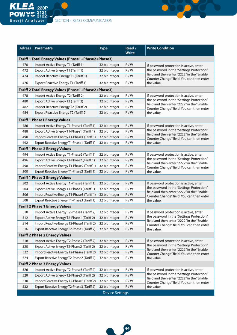
Tariff 1 Total Energy Values (Phase1+Phase2+Phase3)470 Import Active Energy T1 (Tariff 1) 32 bit integer R / W If password protection is active, enter
the password in the “Settings Protection” field and then enter “2222” in the “Enable Counter Change” field. You can then enter the value.
472 Export Active Energy T1 (Tariff 1) 32 bit integer R / W
474 Import Reactive Energy T1 (Tariff 1) 32 bit integer R / W
476 Export Reactive Energy T1 (Tariff 1) 32 bit integer R / W
Tariff 2 Total Energy Values (Phase1+Phase2+Phase3)478 Import Active Energy T2 (Tariff 2) 32 bit integer R / W If password protection is active, enter
the password in the “Settings Protection” field and then enter “2222” in the “Enable Counter Change” field. You can then enter the value.
480 Export Active Energy T2 (Tariff 2) 32 bit integer R / W
482 Import Reactive Energy T2 (Tariff 2) 32 bit integer R / W
484 Export Reactive Energy T2 (Tariff 2) 32 bit integer R / W
Tariff 1 Phase1 Energy Values486 Import Active Energy T1-Phase1 (Tariff 1) 32 bit integer R / W If password protection is active, enter
the password in the “Settings Protection” field and then enter “2222” in the “Enable Counter Change” field. You can then enter the value.
488 Export Active Energy T1-Phase1 (Tariff 1) 32 bit integer R / W
490 Import Reactive Energy T1-Phase1 (Tariff 1) 32 bit integer R / W
492 Export Reactive Energy T1-Phase1 (Tariff 1) 32 bit integer R / W
Tariff 1 Phase 2 Energy Values494 Import Active Energy T1-Phase2 (Tariff 1) 32 bit integer R / W If password protection is active, enter
the password in the “Settings Protection” field and then enter “2222” in the “Enable Counter Change” field. You can then enter the value.
496 Export Active Energy T1-Phase2 (Tariff 1) 32 bit integer R / W
498 Import Reactive Energy T1-Phase2 (Tariff 1) 32 bit integer R / W
500 Export Reactive Energy T1-Phase2 (Tariff 1) 32 bit integer R / W
Tariff 1 Phase 3 Energy Values502 Import Active Energy T1-Phase3 (Tariff 1) 32 bit integer R / W If password protection is active, enter
the password in the “Settings Protection” field and then enter “2222” in the “Enable Counter Change” field. You can then enter the value.
504 Export Active Energy T1-Phase3 (Tariff 1) 32 bit integer R / W
506 Import Reactive Energy T1-Phase3 (Tariff 1) 32 bit integer R / W
508 Export Reactive Energy T1-Phase3 (Tariff 1) 32 bit integer R / W
Tariff 2 Phase 1 Energy Values510 Import Active Energy T2-Phase1 (Tariff 2) 32 bit integer R / W If password protection is active, enter
the password in the “Settings Protection” field and then enter “2222” in the “Enable Counter Change” field. You can then enter the value.
512 Export Active Energy T2-Phase1 (Tariff 2) 32 bit integer R / W
514 Import Reactive Energy T2-Phase1 (Tariff 2) 32 bit integer R / W
516 Export Reactive Energy T2-Phase1 (Tariff 2) 32 bit integer R / W
Tariff 2 Phase 2 Energy Values518 Import Active Energy T2-Phase2 (Tariff 2) 32 bit integer R / W If password protection is active, enter
the password in the “Settings Protection” field and then enter “2222” in the “Enable Counter Change” field. You can then enter the value.
520 Export Active Energy T2-Phase2 (Tariff 2) 32 bit integer R / W
522 Import Reactive Energy T2-Phase2 (Tariff 2) 32 bit integer R / W
524 Export Reactive Energy T2-Phase2 (Tariff 2) 32 bit integer R / W
Tariff 2 Phase 3 Energy Values526 Import Active Energy T2-Phase3 (Tariff 2) 32 bit integer R / W If password protection is active, enter
the password in the “Settings Protection” field and then enter “2222” in the “Enable Counter Change” field. You can then enter the value.
528 Export Active Energy T2-Phase3 (Tariff 2) 32 bit integer R / W
530 Import Reactive Energy T2-Phase3 (Tariff 2) 32 bit integer R / W
532 Export Reactive Energy T2-Phase3 (Tariff 2) 32 bit integer R / W
Device Settings
SECTION 4 RS485 COMMUNICATION
45
E n e r j i A n a l y z e r
31213122
Adress Parametre Type Read / Write
Write Condition
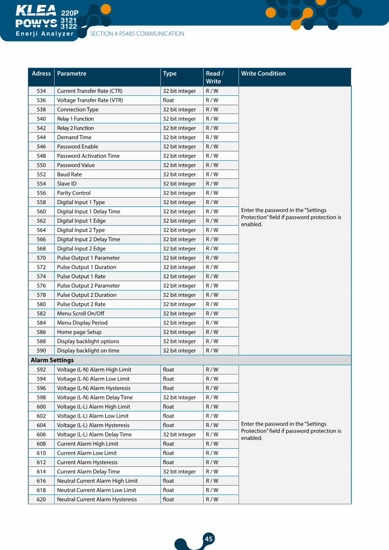
534 Current Transfer Rate (CTR) 32 bit integer R / W
Enter the password in the “Settings Protection” field if password protection is enabled.
536 Voltage Transfer Rate (VTR) float R / W
538 Connection Type 32 bit integer R / W
540 Relay 1 Function 32 bit integer R / W
542 Relay 2 Function 32 bit integer R / W
544 Demand Time 32 bit integer R / W
546 Password Enable 32 bit integer R / W
548 Password Activation Time 32 bit integer R / W
550 Password Value 32 bit integer R / W
552 Baud Rate 32 bit integer R / W
554 Slave ID 32 bit integer R / W
556 Parity Control 32 bit integer R / W
558 Digital Input 1 Type 32 bit integer R / W
560 Digital Input 1 Delay Time 32 bit integer R / W
562 Digital Input 1 Edge 32 bit integer R / W
564 Digital Input 2 Type 32 bit integer R / W
566 Digital Input 2 Delay Time 32 bit integer R / W
568 Digital Input 2 Edge 32 bit integer R / W
570 Pulse Output 1 Parameter 32 bit integer R / W
572 Pulse Output 1 Duration 32 bit integer R / W
574 Pulse Output 1 Rate 32 bit integer R / W
576 Pulse Output 2 Parameter 32 bit integer R / W
578 Pulse Output 2 Duration 32 bit integer R / W
580 Pulse Output 2 Rate 32 bit integer R / W
582 Menu Scroll On/Off 32 bit integer R / W
584 Menu Display Period 32 bit integer R / W
586 Home page Setup 32 bit integer R / W
588 Display backlight options 32 bit integer R / W
590 Display backlight on time 32 bit integer R / W
Alarm Settings592 Voltage (L-N) Alarm High Limit float R / W
Enter the password in the “Settings Protection” field if password protection is enabled.
594 Voltage (L-N) Alarm Low Limit float R / W
596 Voltage (L-N) Alarm Hysteresis float R / W
598 Voltage (L-N) Alarm Delay Time 32 bit integer R / W
600 Voltage (L-L) Alarm High Limit float R / W
602 Voltage (L-L) Alarm Low Limit float R / W
604 Voltage (L-L) Alarm Hysteresis float R / W
606 Voltage (L-L) Alarm Delay Time 32 bit integer R / W
608 Current Alarm High Limit float R / W
610 Current Alarm Low Limit float R / W
612 Current Alarm Hysteresis float R / W
614 Current Alarm Delay Time 32 bit integer R / W
616 Neutral Current Alarm High Limit float R / W
618 Neutral Current Alarm Low Limit float R / W
620 Neutral Current Alarm Hysteresis float R / W
SECTION 4 RS485 COMMUNICATION

46
E n e r j i A n a l y z e r
31213122
Adress Parametre Type Read / Write
Write Condition
622 Neutral Current Alarm Delay Time 32 bit integer R / W
Enter the password in the “Settings Protection” field if password protection is enabled.
624 Cosφ Alarm High Limit float R / W
626 Cosφ Alarm Low Limit float R / W
628 Cosφ Alarm Hysteresis float R / W
630 Cosφ Alarm Delay Time 32 bit integer R / W
632 Power Factor Alarm High Limit float R / W
634 Power Factor Alarm Low Limit float R / W
636 Power Factor Alarm Hysteresis float R / W
638 Power Factor Alarm Delay Time 32 bit integer R / W
640 Frequency Alarm High Limit float R / W
642 Frequency Alarm Low Limit float R / W
644 Frequency Alarm Hysteresis float R / W
646 Frequency Alarm Delay Time 32 bit integer R / W
Device Model648 Device Firmware Version float RO
650 Device Model 32 bit integer RO
Password /Pin activation652 Setting protection 32 bit integer R / W Address for the device password. It displays
the enabled/disabled condition of the password protection when reading using
Reset Commands1000 Reset Energy Values 32 bit integer WO
Enter the password in the “Settings Protection” field if password protection is enabled. Enter “1” into the respective address to reset the values. Enter “0” before saving to restore the values.
1002 Reset Counter Values 32 bit integer WO
1004 Reset Max. Values 32 bit integer WO
1006 Reset Min. Values 32 bit integer WO
1008 Reset Demand Values 32 bit integer WO
1010 Reset Settings 32 bit integer WO
1012 Reset Alarm Limits 32 bit integer WO
1014 Reset the Device to Factory Settings 32 bit integer WO
Save The Changes
2000 Save Changes 32 bit integer WO
Enter the password in the "Settings Protection" field if password protection is enabled. Enter "1" to save the changes and restart.
Manual Output Relay Control4000 Enable Relay Control 32 bit integer WO Enter the password in the "Settings
Protection" field if password protection is enabled. Enter "1111" here to enable the relay control. Enter "0" here to disable the relay control.
4002 Relay 1 Control 32 bit integer WO Enter the password in the "Settings Protection" field if password prote- ction is enabled. Then, enter "1111" for the "Enable Relay Control" address. Enter "1" to activate, "0" to de-activate the relay.
4004 Relay 1 Control 32 bit integer WO Enter the password in the "Settings Protection" field if password prote- ction is enabled. Then, enter "1111" for the "Enable Relay Control" address. Enter "1" to activate, "0" to de-activate the relay.
SECTION 4 RS485 COMMUNICATION
47
E n e r j i A n a l y z e r
31213122
Adress Parametre Type Read / Write
Write Condition
Enable/Disable to Assigning Predefined Value for Energy Meters
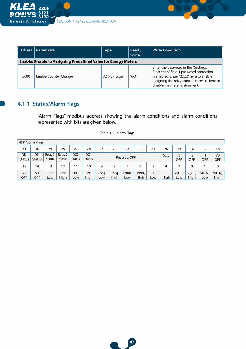
5000 Enable Counter Change 32 bit integer WO
Enter the password in the "Settings Protection" field if password protection is enabled. Enter "2222" here to enable assigning the relay control. Enter "0" here to disable the meter assignment.
4.1.1 Status/Alarm Flags
“Alarm Flags” modbus address showing the alarm conditions and alarm conditions represented with bits are given below.
Table 4-2 Alarm Flags
458 Alarm Flags
31 30 29 28 27 26 25 24 23 22 21 20 19 18 17 16
Reserve/OFF SEQ I3 OFF
I2 OFF
I1 OFF
V3 OFF
15 14 13 12 11 10 9 8 7 6 5 4 3 2 1 0
V2 OFF
V1 OFF
Freq Low
Freq High
PF Low
PF High
Cosφ Low
Cosφ High
I(Nötr) Low
I(Nötr) High
I Low
I High
V(L-L) Low
V(L-L) High
V(L-N) Low
V(L-N) High
Dl2Status
Dl1Status
Relay 2Status
Relay 2Status
DO2Status
DO1Status
SECTION 4 RS485 COMMUNICATION
48
E n e r j i A n a l y z e r
31213122
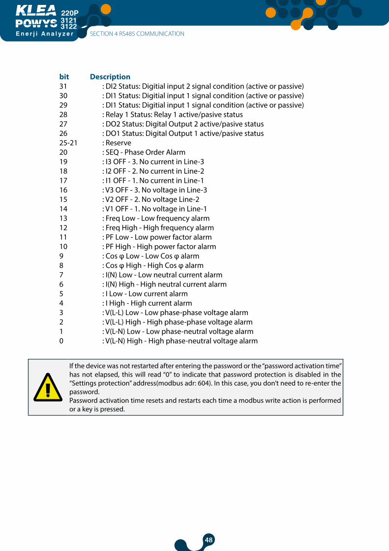
bit Description31 : DI2 Status: Digitial input 2 signal condition (active or passive)30 : DI1 Status: Digitial input 1 signal condition (active or passive)29 : DI1 Status: Digitial input 1 signal condition (active or passive)28 : Relay 1 Status: Relay 1 active/pasive status27 : DO2 Status: Digital Output 2 active/pasive status26 : DO1 Status: Digital Output 1 active/pasive status 25-21 : Reserve20 : SEQ - Phase Order Alarm19 : I3 OFF - 3. No current in Line-318 : I2 OFF - 2. No current in Line-217 : I1 OFF - 1. No current in Line-116 : V3 OFF - 3. No voltage in Line-315 : V2 OFF - 2. No voltage Line-214 : V1 OFF - 1. No voltage in Line-113 : Freq Low - Low frequency alarm12 : Freq High - High frequency alarm 11 : PF Low - Low power factor alarm10 : PF High - High power factor alarm9 : Cos φ Low - Low Cos φ alarm8 : Cos φ High - High Cos φ alarm7 : I(N) Low - Low neutral current alarm6 : I(N) High - High neutral current alarm5 : I Low - Low current alarm4 : I High - High current alarm3 : V(L-L) Low - Low phase-phase voltage alarm2 : V(L-L) High - High phase-phase voltage alarm1 : V(L-N) Low - Low phase-neutral voltage alarm0 : V(L-N) High - High phase-neutral voltage alarm
If the device was not restarted after entering the password or the “password activation time” has not elapsed, this will read “0” to indicate that password protection is disabled in the “Settings protection” address(modbus adr: 604). In this case, you don’t need to re-enter the password.Password activation time resets and restarts each time a modbus write action is performed or a key is pressed.
SECTION 4 RS485 COMMUNICATION
49
E n e r j i A n a l y z e r
31213122
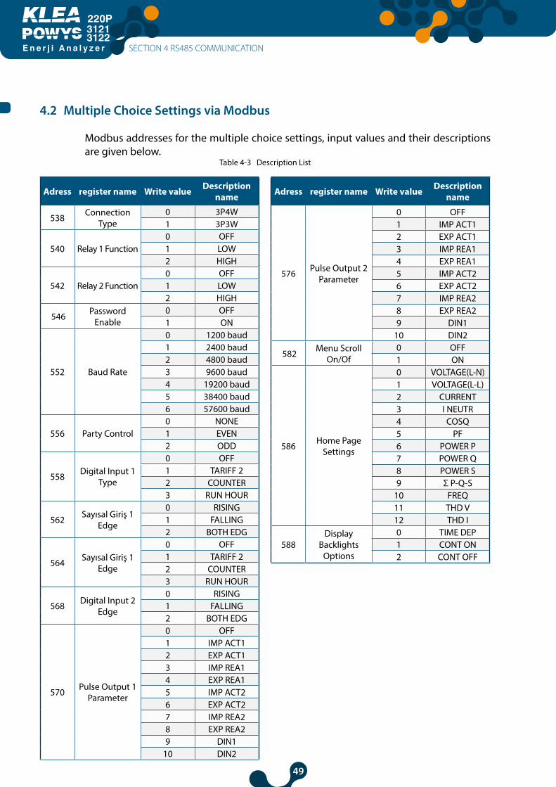
4.2 Multiple Choice Settings via Modbus
Modbus addresses for the multiple choice settings, input values and their descriptions are given below.
Table 4-3 Description List
Adress register name Write value Description name
538 Connection Type
0 3P4W1 3P3W
540 Relay 1 Function0 OFF1 LOW2 HIGH
542 Relay 2 Function0 OFF1 LOW2 HIGH
546 Password Enable
0 OFF1 ON
552 Baud Rate
0 1200 baud1 2400 baud2 4800 baud3 9600 baud4 19200 baud5 38400 baud6 57600 baud
556 Party Control0 NONE1 EVEN2 ODD
558 Digital Input 1 Type
0 OFF1 TARIFF 22 COUNTER3 RUN HOUR
562 Sayısal Giriş 1 Edge
0 RISING1 FALLING2 BOTH EDG
564 Sayısal Giriş 1 Edge
0 OFF1 TARIFF 22 COUNTER3 RUN HOUR
568 Digital Input 2 Edge
0 RISING1 FALLING2 BOTH EDG
570 Pulse Output 1 Parameter
0 OFF1 IMP ACT12 EXP ACT13 IMP REA14 EXP REA15 IMP ACT26 EXP ACT27 IMP REA28 EXP REA29 DIN1
10 DIN2
Adress register name Write value Description name
576 Pulse Output 2 Parameter
0 OFF1 IMP ACT12 EXP ACT13 IMP REA14 EXP REA15 IMP ACT26 EXP ACT27 IMP REA28 EXP REA29 DIN1
10 DIN2
582 Menu Scroll On/Of
0 OFF1 ON
586 Home Page Settings
0 VOLTAGE(L-N)1 VOLTAGE(L-L)2 CURRENT3 I NEUTR4 COSQ5 PF6 POWER P7 POWER Q8 POWER S9 Σ P-Q-S
10 FREQ11 THD V12 THD I
588Display
Backlights Options
0 TIME DEP1 CONT ON2 CONT OFF
SECTION 4 RS485 COMMUNICATION

50
E n e r j i A n a l y z e r
31213122
SECTION 5FACTORY DEFAULT
SETTINGS
EnergyAnalyzer
220P
3121-3122
51
E n e r j i A n a l y z e r
31213122
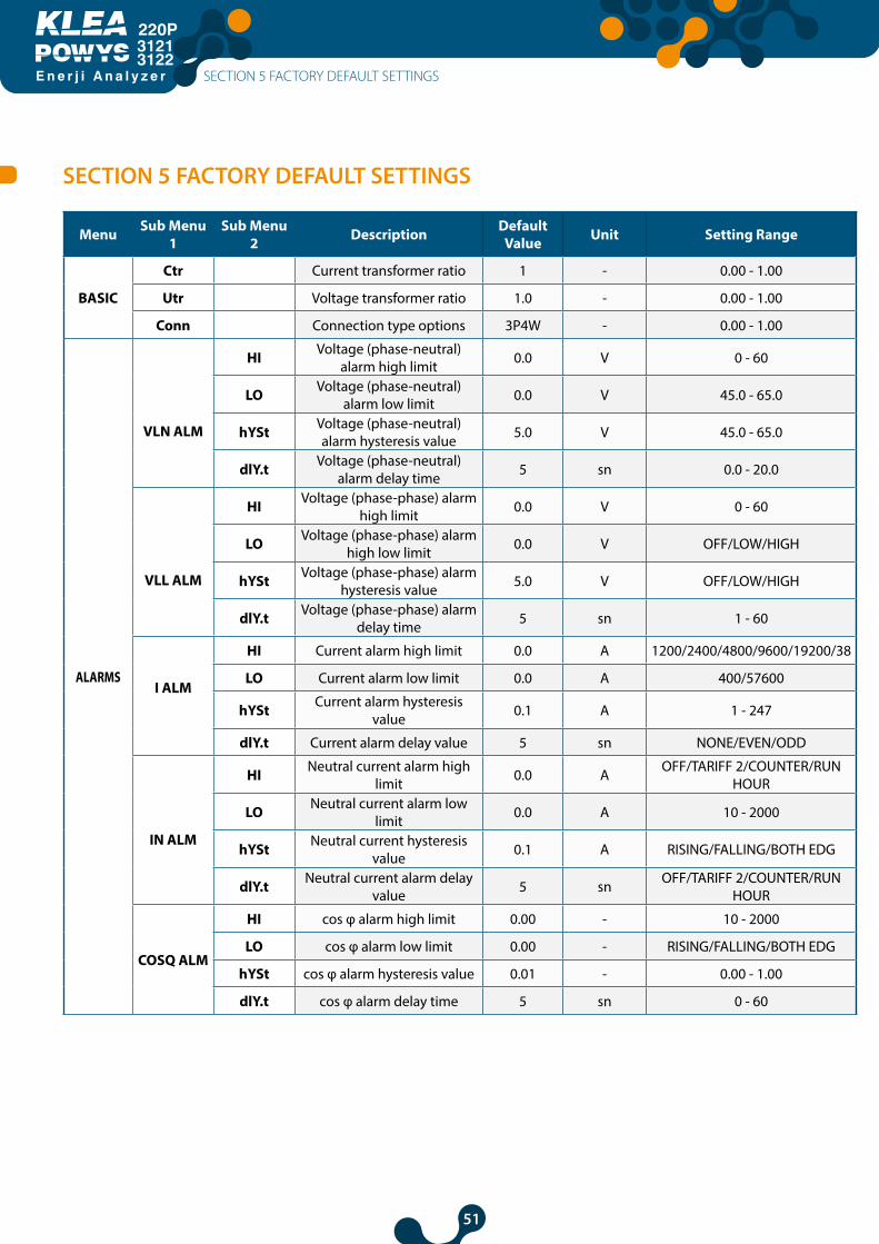
SECTION 5 FACTORY DEFAULT SETTINGS
Menu Sub Menu 1
Sub Menu 2 Description Default
Value Unit Setting Range
BASIC
Ctr Current transformer ratio 1 - 0.00 - 1.00
Utr Voltage transformer ratio 1.0 - 0.00 - 1.00
Conn Connection type options 3P4W - 0.00 - 1.00
ALARMS
VLN ALM
HI Voltage (phase-neutral) alarm high limit 0.0 V 0 - 60
LO Voltage (phase-neutral) alarm low limit 0.0 V 45.0 - 65.0
hYSt Voltage (phase-neutral) alarm hysteresis value 5.0 V 45.0 - 65.0
dlY.t Voltage (phase-neutral) alarm delay time 5 sn 0.0 - 20.0
VLL ALM
HI Voltage (phase-phase) alarm high limit 0.0 V 0 - 60
LO Voltage (phase-phase) alarm high low limit 0.0 V OFF/LOW/HIGH
hYSt Voltage (phase-phase) alarm hysteresis value 5.0 V OFF/LOW/HIGH
dlY.t Voltage (phase-phase) alarm delay time 5 sn 1 - 60
I ALM
HI Current alarm high limit 0.0 A 1200/2400/4800/9600/19200/38
LO Current alarm low limit 0.0 A 400/57600
hYSt Current alarm hysteresis value 0.1 A 1 - 247
dlY.t Current alarm delay value 5 sn NONE/EVEN/ODD
IN ALM
HI Neutral current alarm high limit 0.0 A OFF/TARIFF 2/COUNTER/RUN
HOUR
LO Neutral current alarm low limit 0.0 A 10 - 2000
hYSt Neutral current hysteresis value 0.1 A RISING/FALLING/BOTH EDG
dlY.t Neutral current alarm delay value 5 sn OFF/TARIFF 2/COUNTER/RUN
HOUR
COSQ ALM
HI cos φ alarm high limit 0.00 - 10 - 2000
LO cos φ alarm low limit 0.00 - RISING/FALLING/BOTH EDG
hYSt cos φ alarm hysteresis value 0.01 - 0.00 - 1.00
dlY.t cos φ alarm delay time 5 sn 0 - 60
SECTION 5 FACTORY DEFAULT SETTINGS

52
E n e r j i A n a l y z e r
31213122
Menu Sub Menu 1
Sub Menu 2 Description Default
Value Unit Setting Range
ALARMS
PF ALM
HI Power factor alarm high limit 0.00 - 0.00 - 1.00
LO Power factor alarm low limit 0.00 - 0.00 - 1.00
hYSt Power factor alarm hysteresis value 0.01 - 0.00 - 1.00
dlY.t Power factor alarm delay time 5 sn 0 - 60
FREQ ALM
HI Frequency alarm high limit 50.0 Hz 45.0 - 65.0
LO Frequency alarm low limit 50.0 Hz 45.0 - 65.0
hYSt Frequency alarm hysteresis value 2.0 Hz 0.0 - 20.0
dlY.t Frequency alarm delay time 5 sn 0 - 60
RELAYS rLY1 Relay 1 setup OFF - OFF/LOW/HIGH
rLY2 Relay 2 setup OFF - OFF/LOW/HIGH
DEMAND dEd.s Demand time setup 15 dk 1 - 60
RS485
bAud Baud rate options 38400 Baud 1200/2400/4800/9600/19200/38400/57600
Id Slave ID setup 1 - 1 - 247
PrtY Parity check setup NONE - NONE/EVEN/ODD
DI INPUT
INPUT1
tYPE Digital input 1 options OFF - OFF/TARIFF 2/COUNTER/RUN HOUR
dLY Digital input 1 detection delay time 10 msn 10 - 2000
EdgE Digital input 1 detection edge RISING - RISING/FALLING/BOTH EDG
INPUT2
tYPE Digital input 2 options OFF - OFF/TARIFF 2/COUNTER/RUN HOUR
dLY Digital input 2 detection delay time 10 msn 10 - 2000
Digital input 2 detection edge RISING - RISING/FALLING/BOTH EDG
PULSE
OUT1
OUT Pulse output 1 parameter setup OFF -
OFF / IMP ACT1 / EXP ACT1 / IMP REA1 / EXP REA1 / IMP ACT2 /
EXP ACT2 / IMP REA2 / EXP REA2/ DIN1 / DIN2
durA Pulse duration of the pulse output 1 50 msn 50 - 2500
rAt Step range for pulse output 1 1 kWh/kVArhQty 1 - 99 999 999
OUT2
OUT Pulse output 2 parameter setup OFF -
OFF / IMP ACT1 / EXP ACT1 / IMP REA1 / EXP REA1 / IMP ACT2 /
EXP ACT2 / IMP REA2 / EXP REA2/ DIN1 / DIN2
durA Pulse duration of the pulse output 2 50 msn 50 - 2500
Step range for pulse output 2 1 kWh / kVarh Qty 1 - 99 999 999
SECTION 5 FACTORY DEFAULT SETTINGS
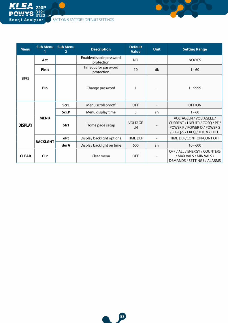
53
E n e r j i A n a l y z e r
31213122
Menu Sub Menu 1
Sub Menu 2 Description Default
Value Unit Setting Range
SIFRE
Act Enable/disable password protection NO - NO/YES
Pin.t Timeout for password protection 10 dk 1 - 60
Pin Change password 1 - 1 - 9999
DISPLAY
MENU
ScrL Menu scroll on/off OFF - OFF/ON
Scr.P Menu display time 3 sn 1 - 60
Strt Home page setup VOLTAGE LN -
VOLTAGELN / VOLTAGELL / CURRENT / I NEUTR / COSQ / PF / POWER P / POWER Q / POWER S/ Σ P-Q-S / FREQ / THD V / THD I
BACKLGHToPt Display backlight options TIME DEP - TIME DEP/CONT ON/CONT OFF
durA Display backlight on time 600 sn 10 - 600
CLEAR CLr Clear menu OFF -OFF / ALL / ENERGY / COUNTERS
/ MAX VALS / MIN VALS / DEMANDS / SETTINGS / ALARMS
SECTION 5 FACTORY DEFAULT SETTINGS

54
E n e r j i A n a l y z e r
31213122
SECTION 5 FABRİKA ÖN DEĞERLERİ
SECTION 6TECHNICAL
SPECIFICATIONS
EnergyAnalyzer
220P
3121-3122
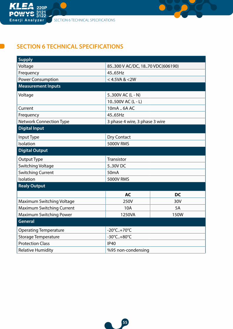
55
E n e r j i A n a l y z e r
31213122
SECTION 6 TECHNICAL SPECIFICATIONS
SupplyVoltage 85..300 V AC/DC, 18..70 VDC(606190)Frequency 45..65HzPower Consumption < 4.5VA & <2WMeasurement Inputs
Voltage 5..300V AC (L - N)10..500V AC (L - L)
Current 10mA .. 6A ACFrequency 45..65HzNetwork Connection Type 3 phase 4 wire, 3 phase 3 wireDigital Input
Input Type Dry ContactIsolation 5000V RMSDigital Output
Output Type TransistorSwitching Voltage 5..30V DCSwitching Current 50mAIsolation 5000V RMSRealy Output
AC DCMaximum Switching Voltage 250V 30VMaximum Switching Current 10A 5AMaximum Switching Power 1250VA 150WGeneral
Operating Temperature -20°C..+70°CStorage Temperature -30°C..+80°CProtection Class IP40Relative Humidity %95 non-condensing
SECTION 6 TECHNICAL SPECIFICATIONS
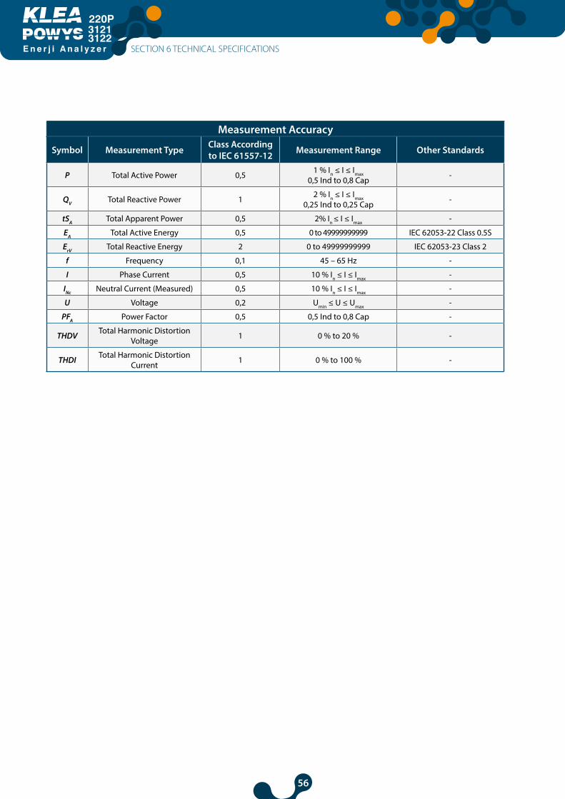
56
E n e r j i A n a l y z e r
31213122
Measurement Accuracy
Symbol Measurement Type Class According to IEC 61557-12 Measurement Range Other Standards
P Total Active Power 0,5 1 % In ≤ I ≤ Imax 0,5 Ind to 0,8 Cap -
QV Total Reactive Power 1 2 % In ≤ I ≤ Imax 0,25 Ind to 0,25 Cap -
tSA Total Apparent Power 0,5 2% In ≤ I ≤ Imax -
EA Total Active Energy 0,5 0 to 49999999999 IEC 62053-22 Class 0.5S
ErV Total Reactive Energy 2 0 to 49999999999 IEC 62053-23 Class 2
f Frequency 0,1 45 – 65 Hz -
I Phase Current 0,5 10 % In ≤ I ≤ Imax -
INc Neutral Current (Measured) 0,5 10 % In ≤ I ≤ Imax -
U Voltage 0,2 Umin ≤ U ≤ Umax -
PFA Power Factor 0,5 0,5 Ind to 0,8 Cap -
THDV Total Harmonic Distortion Voltage 1 0 % to 20 % -
THDI Total Harmonic Distortion Current 1 0 % to 100 % -
SECTION 6 TECHNICAL SPECIFICATIONS

57
E n e r j i A n a l y z e r
31213122
Revision No: 16092019www.klemsan.com / [email protected]
Kızılüzüm Mahallesi Kemalpaşa Kızılüzüm Cad. No:15 - 35730 Kemalpaşa - İzmir / TURKEY Tel: (+90 232) 877 08 00 Fax: (+90 232) 877 08 06


