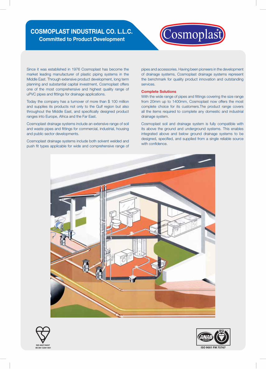
QUALITY ASSURED PRODUCTSCosmoplast drainage systems are manufactured
according to the latest European Standards, and are
subject to very strict Quality Policy supervised by BSI
which enabled Cosmoplast systems to be approved by
the most prestigious International Institutes.
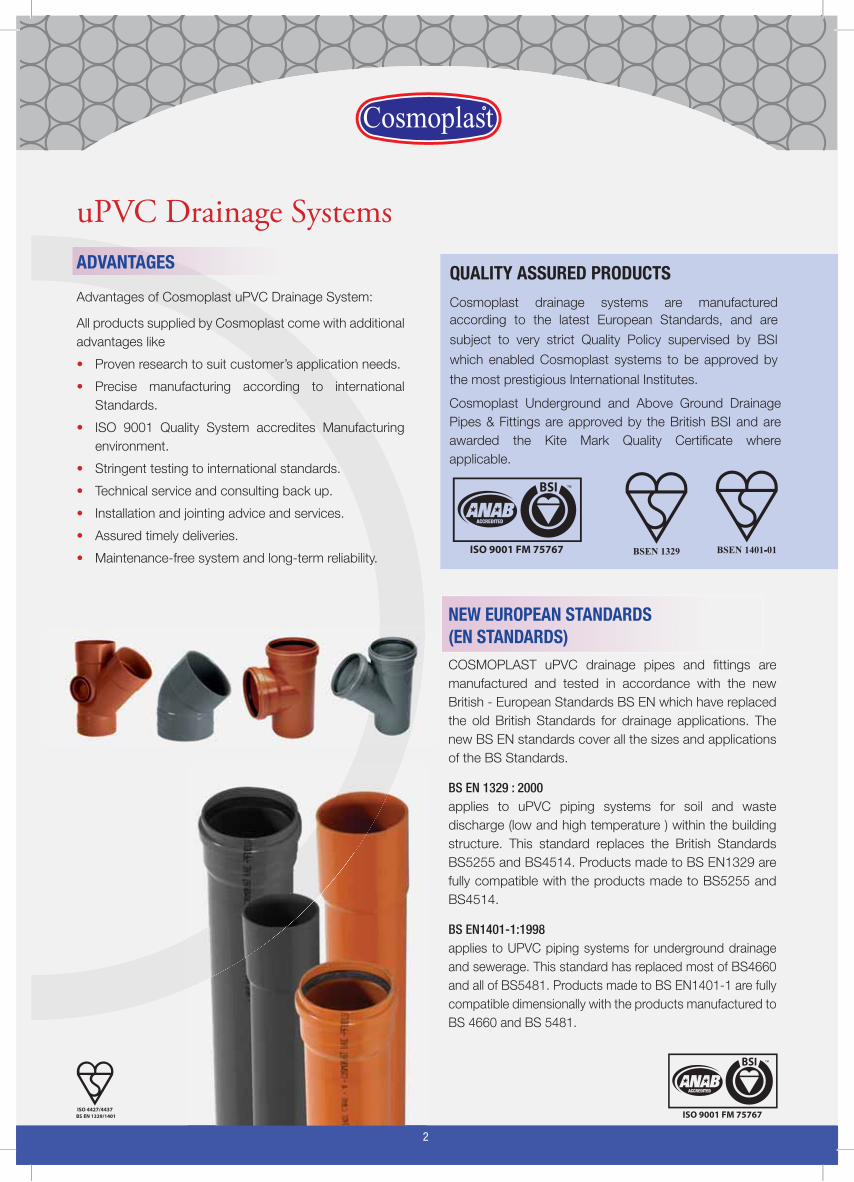
uPVC Drainage SystemsADVANTAGES
Advantages of Cosmoplast uPVC Drainage System:
All products supplied by Cosmoplast come with additional
advantages like
Proven research to suit customer’s application needs.•
Precise manufacturing according to international •
Standards.
ISO 9001 Quality System accredites Manufacturing •
environment.
Stringent testing to international standards.•
Technical service and consulting back up.•
Installation and jointing advice and services.•
Assured timely deliveries.•
Maintenance-free system and long-term reliability.•
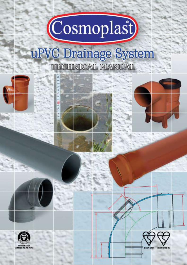
NEW EUROPEAN STANDARDS(EN STANDARDS)COSMOPLAST uPVC drainage pipes and fittings are
manufactured and tested in accordance with the new
British - European Standards BS EN which have replaced
the old British Standards for drainage applications. The
new BS EN standards cover all the sizes and applications
of the BS Standards.
BS EN 1329 : 2000applies to uPVC piping systems for soil and waste
discharge (low and high temperature ) within the building
structure. This standard replaces the British Standards
BS5255 and BS4514. Products made to BS EN1329 are
fully compatible with the products made to BS5255 and
BS4514.
BS EN1401-1:1998applies to UPVC piping systems for underground drainage
and sewerage. This standard has replaced most of BS4660
and all of BS5481. Products made to BS EN1401-1 are fully
compatible dimensionally with the products manufactured to
BS 4660 and BS 5481.
Cosmoplast Underground and Above Ground Drainage
Pipes & Fittings are approved by the British BSI and are
awarded the Kite Mark Quality Certificate where
applicable.
2
3
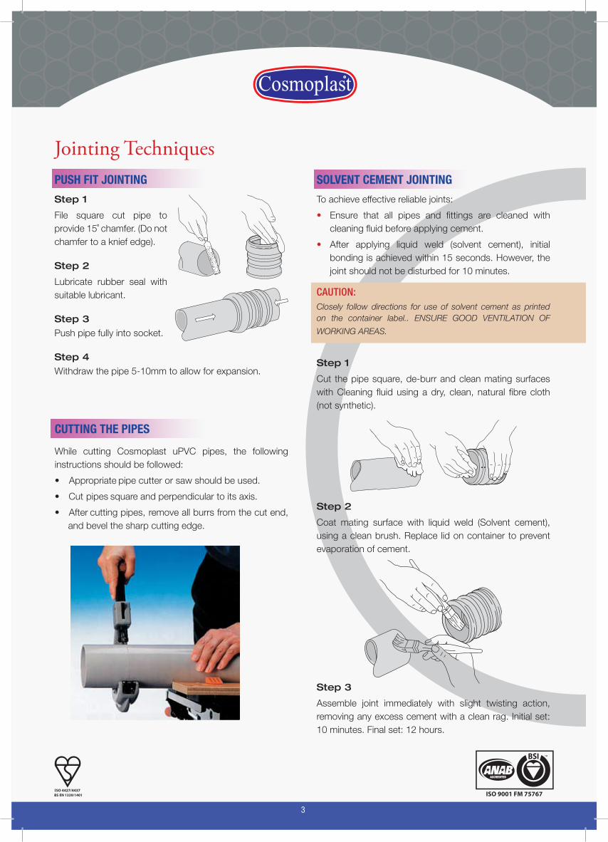
SOLVENT CEMENT JOINTING
To achieve effective reliable joints:
Ensure that all pipes and fittings are cleaned with • cleaning fluid before applying cement.
After applying liquid weld (solvent cement), initial • bonding is achieved within 15 seconds. However, the joint should not be disturbed for 10 minutes.
CAUTION:Closely follow directions for use of solvent cement as printed on the container label.. ENSURE GOOD VENTILATION OF
WORKING AREAS.
Step 1
Cut the pipe square, de-burr and clean mating surfaces with Cleaning fluid using a dry, clean, natural fibre cloth (not synthetic).
Step 2
Coat mating surface with liquid weld (Solvent cement), using a clean brush. Replace lid on container to prevent evaporation of cement.
Step 3
Assemble joint immediately with slight twisting action, removing any excess cement with a clean rag. Initial set: 10 minutes. Final set: 12 hours.
Jointing TechniquesPUSH FIT JOINTING
Step 1
File square cut pipe to provide 15˚ chamfer. (Do not chamfer to a knief edge).
Step 2
Lubricate rubber seal with suitable lubricant.
Step 3Push pipe fully into socket.
Step 4Withdraw the pipe 5-10mm to allow for expansion.
CUTTING THE PIPES
While cutting Cosmoplast uPVC pipes, the following instructions should be followed:
• Appropriate pipe cutter or saw should be used.
• Cut pipes square and perpendicular to its axis.
• After cutting pipes, remove all burrs from the cut end, and bevel the sharp cutting edge.
4
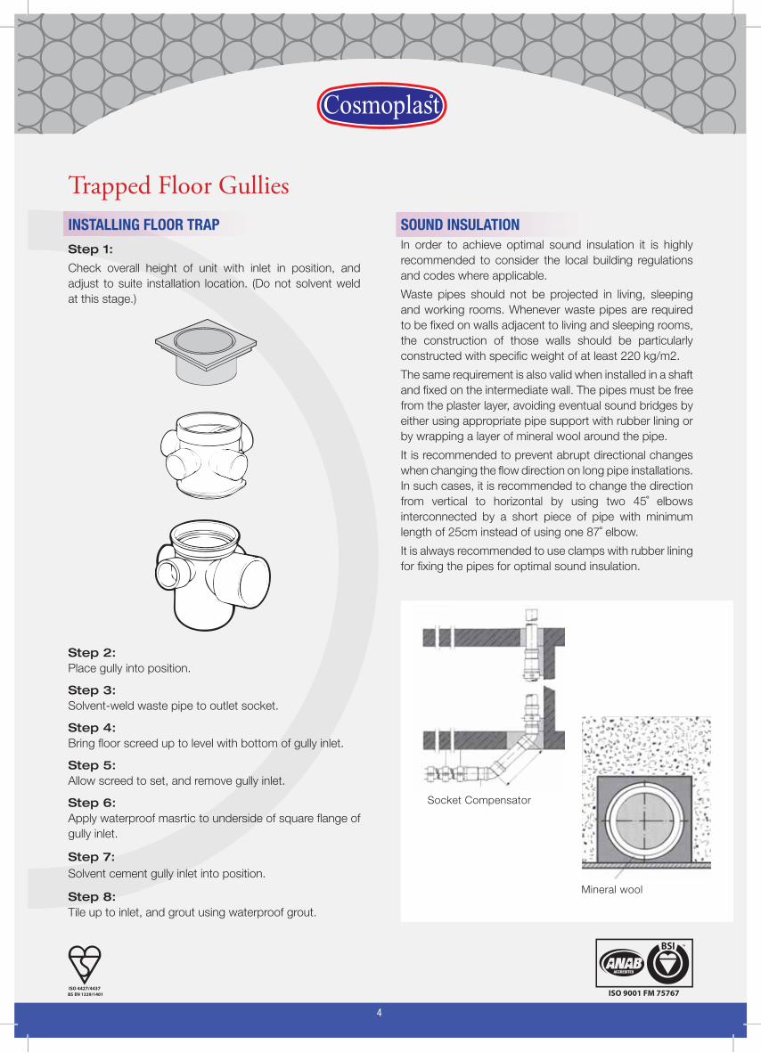
SOUND INSULATIONIn order to achieve optimal sound insulation it is highly
recommended to consider the local building regulations
and codes where applicable.
Waste pipes should not be projected in living, sleeping
and working rooms. Whenever waste pipes are required
to be fixed on walls adjacent to living and sleeping rooms,
the construction of those walls should be particularly
constructed with specific weight of at least 220 kg/m2.
The same requirement is also valid when installed in a shaft
and fixed on the intermediate wall. The pipes must be free
from the plaster layer, avoiding eventual sound bridges by
either using appropriate pipe support with rubber lining or
by wrapping a layer of mineral wool around the pipe.
It is recommended to prevent abrupt directional changes
when changing the flow direction on long pipe installations.
In such cases, it is recommended to change the direction
from vertical to horizontal by using two 45˚ elbows
interconnected by a short piece of pipe with minimum
length of 25cm instead of using one 87˚ elbow.
It is always recommended to use clamps with rubber lining
for fixing the pipes for optimal sound insulation.
Trapped Floor GulliesINSTALLING FLOOR TRAP
Step 1:
Check overall height of unit with inlet in position, and
adjust to suite installation location. (Do not solvent weld
at this stage.)
Step 2:Place gully into position.
Step 3:Solvent-weld waste pipe to outlet socket.
Step 4:Bring floor screed up to level with bottom of gully inlet.
Step 5:Allow screed to set, and remove gully inlet.
Step 6:Apply waterproof masrtic to underside of square flange of
gully inlet.
Step 7:Solvent cement gully inlet into position.
Step 8:Tile up to inlet, and grout using waterproof grout.
Socket Compensator
Mineral wool

5
SUPPORT AND EXPANSION
General Principles
• All pipework must be adequately supported whether
vertical or horizontal.
• Plastic pipework expands and contracts with changes
in temperature - whether ambient temperature or from
the nature of the discharge through the pipework.
Expansion joints must therefore be provided to
accommodate such thermal movement.
• Pipe brackets must be used to anchor expansion
joints. Intermediate support must also be provided to
steady pipework between the points.
• Horizontal pipework requires more frequent support
than vertical pipework (for example, soil stocks)
• On long suspended soil pipe runs (e.g. in basement
areas), sliding joints should be installed to control the
effects of thermal expansion.
• Pipework should always be supported close to any
change of directions (e.g. bends or branches)
FIXING TECHNIQUES
Cosmoplast uPVC drainage pipes and fittings should be
installed tension free and with free lateral allowance for
thermal expansion compensation.
Suitable sound absorbing brackets with rubber lining
should be used to support pipes. Those brackets must be
dimensionally compatible to the pipe diameter. The fixed
bracket creates fixed point in the pipe system.
With fixed brackets the pipe or fitting can not be moved
through the bracket after screws are tightened. In order to
prevent sliding down of vertical pipes, each individual pipe
must be secured on one point by a fixed bracket.
Every horizontally installed pipe should always be fixed with
one fixed bracket. All remaining pipe brackets in horizontal
as well as in vertical installation must be tightened in such
a way to allow sliding.
During installation of horizontal pipes, the bracket distance
should be approximately ten timed the outside diameter of
the pipe. While for vertical installations, brackets are required
every 1 to 2 meters depending on the size of the pipe.
Pipe brackets should not be installed in areas of diameter
reduction and change of directions in the system, this is
required to allow for the thermal expansion.
Pipe brackets should be fixed on building materials with
high strength in order to assure strong and durable pipe
fixing.
Fixed brackets must be installed directly above the fitting
at the bottom of the pipe end. The sliding bracket must be
installed at a distance of maximum of two meters above
the fixed bracket.
In multi-story buildings, the drainage pipes of diameter
110mm or bigger installed inside the mechanical ducts must be secured by additional fixing against sliding.
MAKING SOIL PIPE OFFSETS ON-SITEThis connection is required to offset soil pipe run (e.g. to
by-pass a gutter), and can be easily created on-site with a
length of soil pipe and bends.
Step 1: Measure projection (P) required to take pipe past
obstruction.
L
P
L
Step 2: Determine length of pipe required, noting minimum
offsets possible.
Step 3: Square-cut pipe length and de-burr cut ends.
Step 4: Solvent-weld or Push-Fit into standard bend or
offset bend sockets.
7
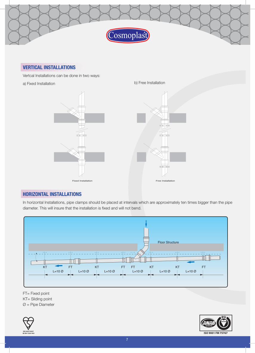
VERTICAL INSTALLATIONS
Vertcal Installations can be done in two ways:
a) Fixed Installation b) Free Installation
HORIZONTAL INSTALLATIONS
In horizontal Installations, pipe clamps should be placed at intervals which are approximately ten times bigger than the pipe
diameter. This will insure that the installation is fixed and will not bend.
FT= Fixed point
KT= Sliding point
Ø = Pipe Diameter
Fixed Installation Free Installation
KT KT KT KTFT FT FT FTL=10 ØL=10 ØL=10 ØL=10 Ø L=10 Ø L=10 Ø
Floor Structure
8
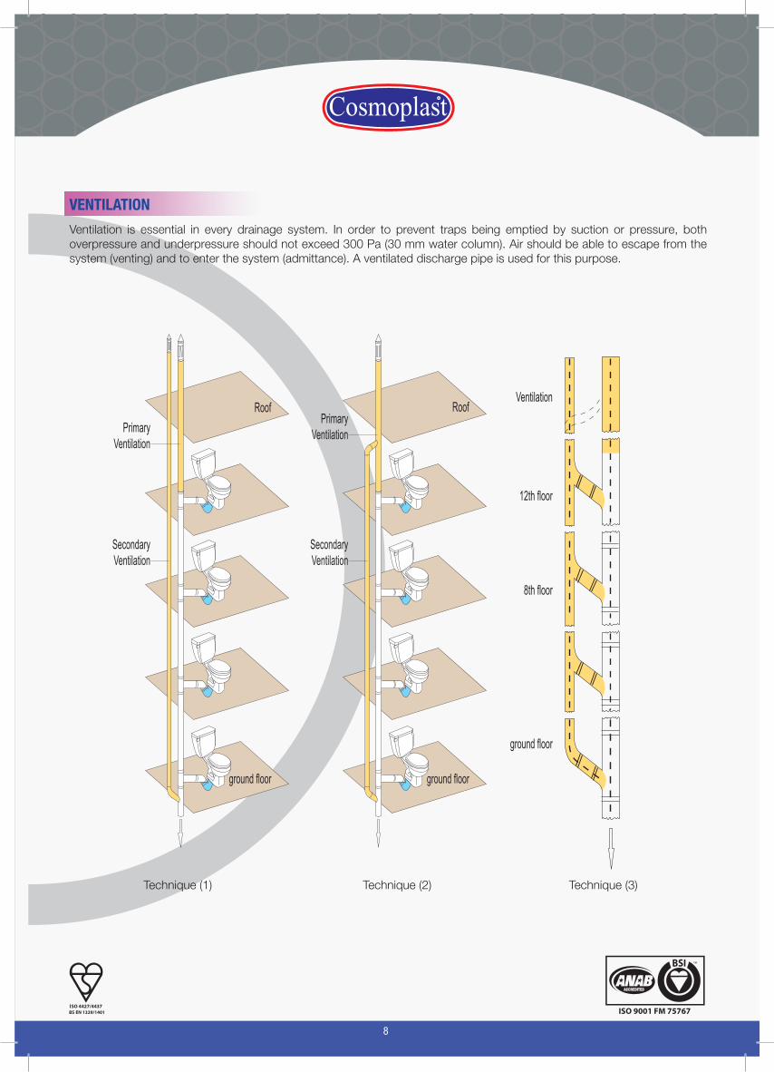
VENTILATION
PrimaryVentilation
SecondaryVentilation
Roof
ground floor
12th floor
Ventilation
8th floor
ground floor
PrimaryVentilation
SecondaryVentilation
Roof
ground floor
Technique (1) Technique (2) Technique (3)
Ventilation is essential in every drainage system. In order to prevent traps being emptied by suction or pressure, both overpressure and underpressure should not exceed 300 Pa (30 mm water column). Air should be able to escape from the system (venting) and to enter the system (admittance). A ventilated discharge pipe is used for this purpose.
9
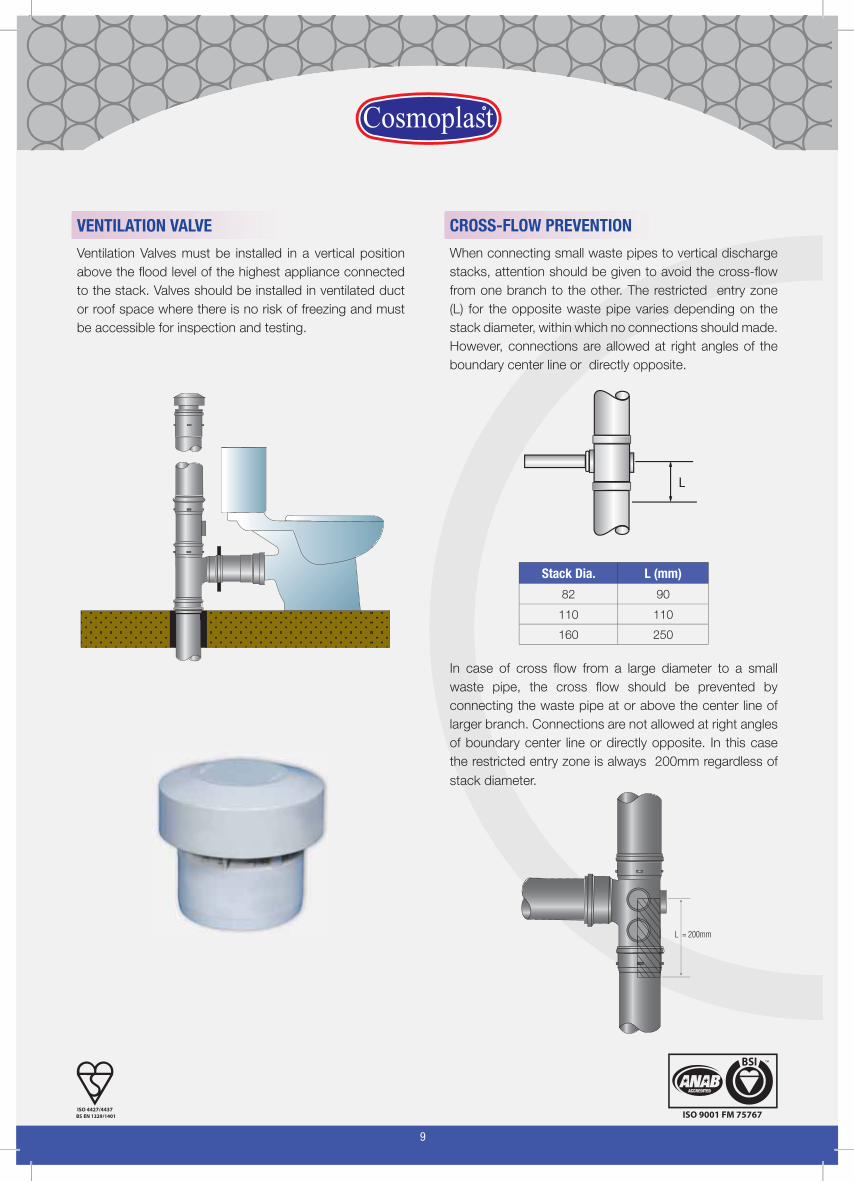
VENTILATION VALVE
Ventilation Valves must be installed in a vertical position
above the flood level of the highest appliance connected
to the stack. Valves should be installed in ventilated duct
or roof space where there is no risk of freezing and must
be accessible for inspection and testing.
CROSS-FLOW PREVENTION
When connecting small waste pipes to vertical discharge
stacks, attention should be given to avoid the cross-flow
enoz yrtne detcirtserehT .rehto eht ot hcnarb eno morf
(L) for the opposite waste pipe varies depending on the
stack diameter, within which no connections should made.
However, connections are allowed at right angles of the
boundary center line or directly opposite.
Stack Dia. L (mm)
82 90
110 110
160 250
In case of cross flow from a large diameter to a small
waste pipe, the cross flow should be prevented by
connecting the waste pipe at or above the center line of
larger branch. Connections are not allowed at right angles
of boundary center line or directly opposite. In this case
the restricted entry zone is always 200mm regardless of
stack diameter.
L = 200mm
10
TESTING DRAINAGE SYSTEMS
Drainage installations should be tested for leaks and defects in new installations and whenever the existing installation is altered, extended or repaired.
All new installations or modified portions should be left uncovered until the testing is successfully completed and approved.
Drainage systems are commonly tested by water and in some cases air test is done. The following are some guidelines for testing drainage systems, while the local codes of practice for each country should be also noted and applied.
Access fittings are also recommended to be installed at the points of connection between underground and above ground pipework, after pipework sections that include multiple bends and long pipe runs and on pipeworks which are casted in concrete.
WATER TEST
All pipe ends and connections must be plugged using suitable testing plugs. Install vertical pipe length to the drain to provide the necessary testing water head.Fill the system with water to maximum height of 3m (30 kPa).The maximum head at the lower parts of the system should never exceed 4.0m, therefore in case of steep gradients the system should be tested in sections.The filled system should be left 2 hours under testing, during which the system should be inspected by measuring the drop in water height. The pipe work should be inspected for any leakage and all defected installations should be repaired and tested again.
•
•
•
•
•
•
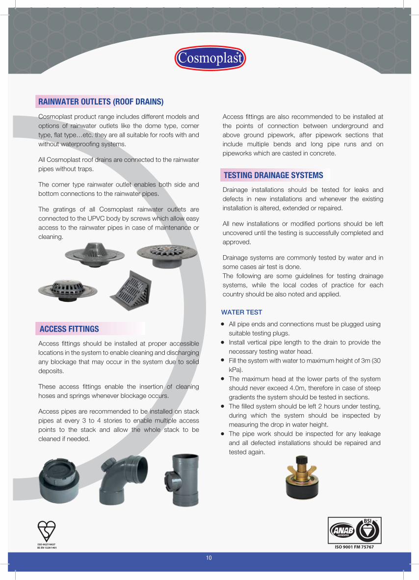
Access fittings should be installed at proper accessible locations in the system to enable cleaning and discharging any blockage that may occur in the system due to solid deposits.
These access fittings enable the insertion of cleaning hoses and springs whenever blockage occurs.
Access pipes are recommended to be installed on stack pipes at every 3 to 4 stories to enable multiple access points to the stack and allow the whole stack to be cleaned if needed.
ACCESS FITTINGS
Cosmoplast product range includes different models and options of rainwater outlets like the dome type, corner type, flat type…etc. they are all suitable for roofs with and without waterproofing systems.
All Cosmoplast roof drains are connected to the rainwater pipes without traps.
The corner type rainwater outlet enables both side and bottom connections to the rainwater pipes.
The gratings of all Cosmoplast rainwater outlets are connected to the UPVC body by screws which allow easy access to the rainwater pipes in case of maintenance or cleaning.
RAINWATER OUTLETS (ROOF DRAINS)

13
MATERIAL PROPERTIES
1 - Corrosion resistance:
uPVC being a non-conductor is totally resistant to all types of galvanic and electromechanical influences which might corrode it. Being non-mettalic, uPVC is resistant to any type of corrosion caused by water as well as a large range of industrial liquids and chemicals. Seepage from high sulphate soils as well as low hardness waters also do not threaten it. This in turn translates into a longer installed life of the uPVC pipe systems.
2- Resistance to biological attack and growth:
uPVC is completely resistant to any microscopic life that it might be exposed to. It does not offer a nourishing source to any bacterial life form and is completely guaranteed to withstand any such growth.
Reaction with Building Materials:
uPVC does not react with any of the normal building materials like cements and paints . However, information about the chemical resistance of uPVC to a wide range of chemicals can be found in the tables of Chemicals Resistance listed in this catalogue.
The following table shows the main physical and thermal properties of the uPVC material:
14
2 - Resistance to Abrasion:
uPVC pipes are highly resistant to abrasion due to stress from abrasion fluids of excessive pressure. Tests have shown that uPVC pipes are up to 2.5 times more resistant to abrasions when compared to steel.
3 - Resistance to biological attack and growth:
uPVC is completely resistant to any microscopic life that it might be exposed to. It does not offer a nourishing source to any bacterial life form and is completely guaranteed to withstand any such growth.
4 - Reaction with Building Materials:
uPVC does not react with any of the normal building materials like cements and paints . However, information about the chemical resistance of uPVC to a wide range of chemicals can be found in the tables of Chemicals Resistance listed in this catalogue.
5 - Thermal Expansion
The coefficient of linear expansion for uPVC is 0.08 mm/m/°K which means less than 1mm per each 1m length in case of a temperature rise of 10°C.
The thermal expansion in drainage systems should be treated by using push fit (rubber rings) fittings and sockets which should be located in suitable locations (BSEN 12056 - Code of Practice for Sanitary Pipework).
6 - Effect of sunlight:
Long exposure to sunlight causes the colour of uPVC to fade, in addition to the reduction of impact strength. The effect of sunlight does not seriously affect the performance of the system, however it is always advisable to protect the system from the direct exposure to sunlight by painting the exposed parts with any exterior glass paint ( paint specialists can recomend the suitable types).
7 - Effect of frost:
The uPVC is not affected by frost, however sub-zero temperatures reduce the impact strength of the uPVC system. Therefore, extra care is to be given while handling and installing uPVC during sub-zero temperatures.
8 - Fire Hazard of uPVC Material:
uPVC pipes and fittings as finished products are not classified as hazardous to health as they exhibit no chemical hazards when used under normal conditions and applications.
uPVC pipes and fittings should be stored in dry and covered places and protected from direct sources of heat and sunlight. It should be noted that the packing cartons and pallets can form a fire risk and may participate in fire spread.
9 - Flammability
uPVC is self-extinguishing material as per BS2782 and fire rated as Class 1 as per BS476 - Part 7 and Class 0 to Part 6.
Due to its flame retardant property, uPVC finished products do not participate in fire. uPVC products have a higher ignition temperature than most of the other thermoplastic and organic materials.
When burns, uPVC form a protective char layer, which in turn act as an insulation layer that stops oxygen.
10 - Fire Fighting
All common fire extinguishers can be used effectively for fighting fires involving PVC.

21
Cosmoplast soil, waste and above ground systems are manufactured from grey unplasticised polyvinyl chloride, uPVC and mUPVC in sizes up to 160mm.
Cosmoplast soil, waste and above ground systems are available in two options:
1. Solvent Welding Type: with sizes from 36mm up to 200mm.
2. Rubber Ring (Push-Fit) Type: with sizes from 56mm up to 250mm.
Both options are suitable for domestic drainage and particular requirements of commercial, industrial and public installations.
Cosmoplast soil, waste and above ground drainage pipes and fittings are manufactured according to the latest European Standard BS EN 1329-1
BSEN 1329 - 1 uPVC DRAINAGE PIPES FOR ABOVE GROUND DRAINAGE
O.D. (mm) W.T. (mm)O.D. (mm) Wall Thickness (mm)
min max min max
36 3.00 36.20 36.45 3.00 3.50
43 3.00 42.75 43.05 3.00 3.50
75 3.00 75.00 75.30 3.00 3.50
56 3.00 55.80 56.05 3.00 3.50
50 3.00 50.00 50.20 3.00 3.50
82 3.00 82.00 82.30 3.00 3.50
110 3.20 110.00 110.30 3.20 3.80
160 3.20 160.00 160.40 3.20 3.80
200 4.90 200.00 200.50 4.90 5.60
250 6.20 250.00 250.50 6.20 7.10
BS 5255 uPVC WASTE PIPES
O.D. W.T. (mm)O.D. (mm) Wall Thickness (mm)
min max min max
1¼” / 36mm 1.80 36.15 36.45 1.80 2.20
1½” / 43mm 1.90 42.75 43.05 1.90 2.30
2” / 56mm 2.00 55.75 56.05 2.00 2.40
uPVC Soil, Waste and Above Ground Discharge System
315 7.70 315.00 315.60 7.70 8.70
22
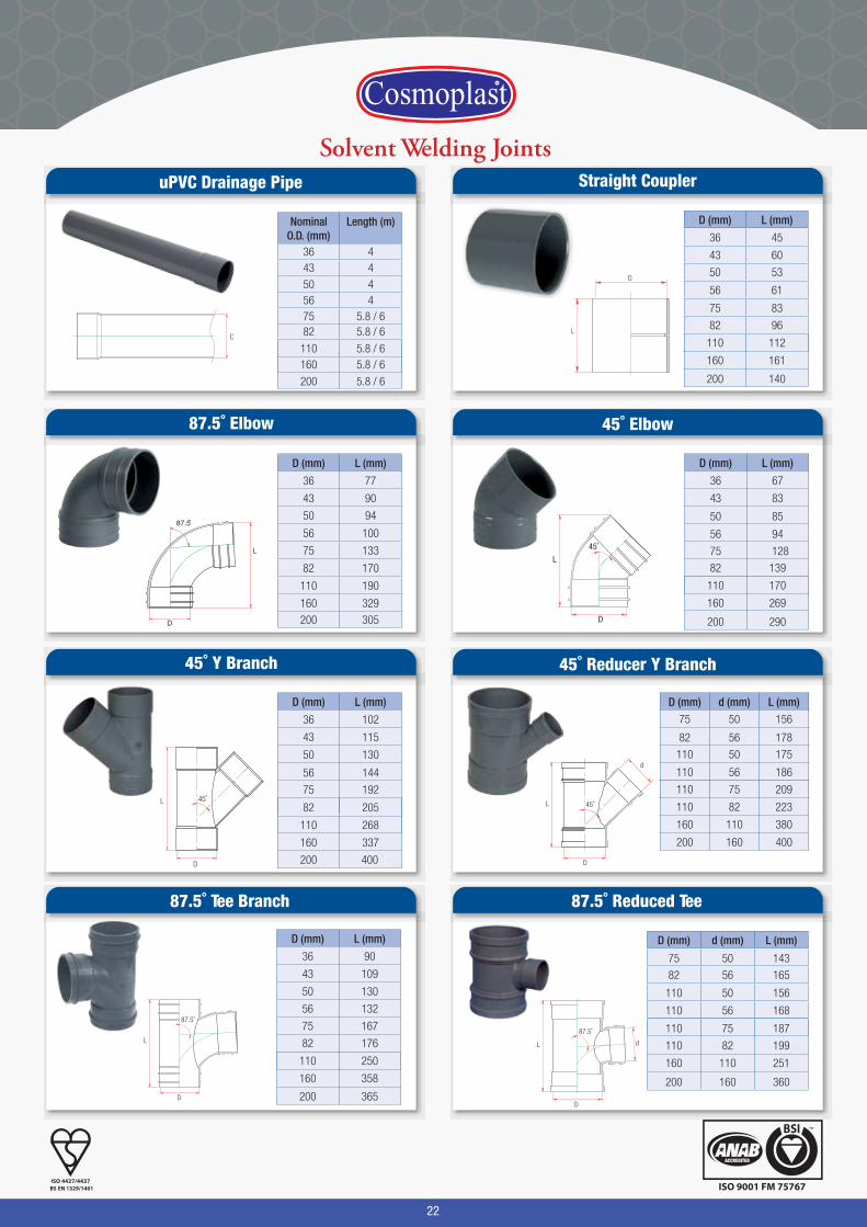
Solvent Welding JointsuPVC Drainage Pipe
87.5˚ Elbow
45˚ Y Branch
45˚ Elbow
45˚ Reducer Y Branch
NominalO.D. (mm)
Length (m)
36 443 4
50 4
200 5.8 / 6
200 5.8 / 6200 5.8 / 6
56 475 5.8 / 682 5.8 / 6
110 5.8 / 6160 5.8 / 6
D (mm) L (mm)
36 77
43 90
56 100
75 133
50 94
82 170
110 190
160 329
200 305
D (mm) L (mm)
36 67
43 83
200 290
200 290
56 94
75 128
50 85
82 139
110 170
160 269
D (mm) L (mm)
36 102
43 115
200 400
200 400
56 144
75 192
50 130
82 205
110 268
160 337
D (mm) d (mm) L (mm)
200 160 400
200 160 400
82 56 178
75 50 156
110 75 209
110 56 186
110 50 175
110 82 223
160 110 380
87.5˚ Tee Branch
D (mm) L (mm)
36 90
43 109
200 365
200 365
56 132
50 130
82 176
75 167
110 250
160 358
L
D
87.5˚
D
L
87.5̊
L
D
d
45˚
L
D
45˚
L
D
45˚
87.5˚ Reduced Tee
D (mm) d (mm) L (mm)
200 75 360
200 160 360
82 56 165
75 50 143
110 56 168
110 75 187
110 50 156
110 82 199
160 110 251
D
87.5˚
L d
Straight Coupler
D (mm) L (mm)
36 45
43 60
50 53
56 61
200 140
200 140
82 96
75 83
110 112
160 161
L
D
D
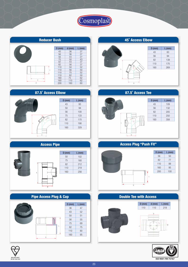
23
D (mm) L (mm)
43 83
56 94
82 139
110 170
160 269
D (mm) L (mm)
43 109
56 132
82 205
110 250
160 358
D (mm) L (mm)
43 93
160 329
160 329
56 100
50 94
82 170
75 133
110 190
D (mm) d (mm) L (mm)43 36 2756 36 2756 43 2775 50 4382 43 3782 56 37
110 56 50110 75 52
110 50 52
110 82 50160 75 62160 110 62200 160 60
Reducer Bush 45˚ Access Elbow
87.5˚ Access Tee87.5˚ Access Elbow
D
L
d
L
D
45˚
L
D
87.5˚
D
L
87.5˚
D (mm) L (mm)
36 47
43 52
50 51
56 55
160 95
Pipe Access Plug & Cap
75 69
110 80
D
L82 75
Access Pipe
D (mm) L (mm)
160 256
82 212
102
16075
50
110 219
L
D
Access Plug “Push Fit”
D (mm) L (mm)
56 50
82 77
110 88
160 95
200 100
D
L
87.5˚
Double Tee with Access
D (mm) d (mm) L (mm)
110 110 219
L
D
D1
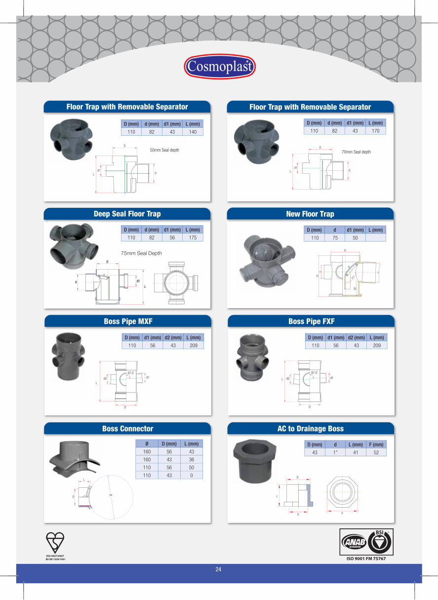
24
Boss Pipe FXF
D (mm) d1 (mm) d2 (mm) L (mm)
110 56 43 209
D
L d2
87.5˚
d1
Boss Pipe MXF
D (mm) d1 (mm) d2 (mm) L (mm)
110 56 43 209
D
Ld2
87.5˚d1
Floor Trap with Removable Separator
D (mm) d (mm) d1 (mm) L (mm)
110 82 43 140
L
D
d1d
50mm Seal depth
Floor Trap with Removable Separator
L
D
d1d
70mm Seal depth
D (mm) d (mm) d1 (mm) L (mm)
110 82 43 170
Deep Seal Floor Trap
D
L
d1d
D (mm) d (mm) d1 (mm) L (mm)
110 82 56 175
75mm Seal Depth
New Floor Trap
D (mm) d d1 (mm) L (mm)
110 75 50
H
D
d2
H1
d1
88.5
o
Boss Connector
Ø D (mm) L (mm)
160 56 43
160 43 36
110 56 50
110 43 0L
D
Ø
AC to Drainage Boss
F
L
D
d
D (mm) d L (mm) F (mm)
43 1” 41 52
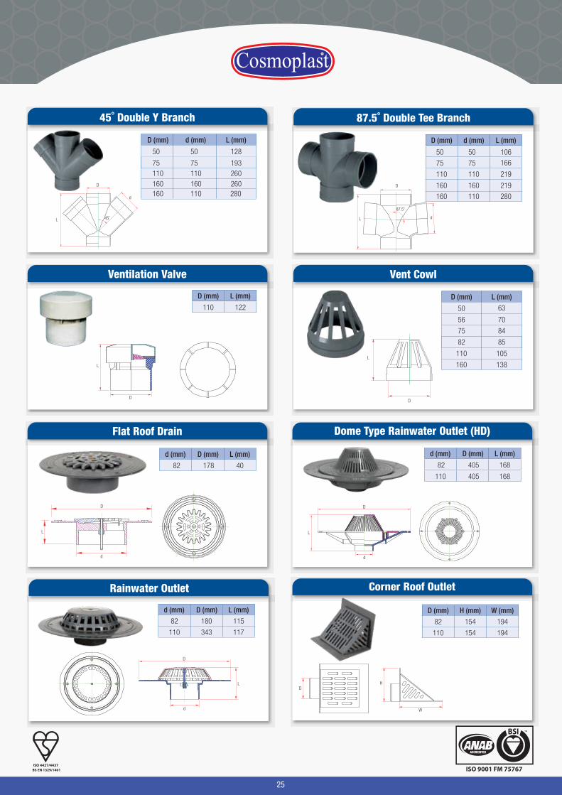
25
Corner Roof Outlet
D (mm) H (mm) W (mm)
82 154 194
110 154 194
D
W
H
Rainwater Outlet
d (mm) D (mm) L (mm)
82 180 115
110 343 117
D
d
L
Dome Type Rainwater Outlet (HD)
d
L
D
d (mm) D (mm) L (mm)
82 405 168
110 405 168
Flat Roof Drain
D
d
L
d (mm) D (mm) L (mm)
82 178 40
d (mm) L (mm)
110 260160
D (mm)
11075 19375
50 12850
160 260110 280160
45˚ Double Y Branch
D
d
L 45˚
D (mm) d (mm) L (mm)
110 110 219
50 50
75 75
106
166
160 160 219
160 110 280
87.5˚ Double Tee Branch
L
D
d
87.5˚
Ventilation Valve
D
L
D (mm) L (mm)
110 122D (mm) L (mm)
160 138
160 138
Vent Cowl
L
D
56 70
63
8475
50
82 85
110 105
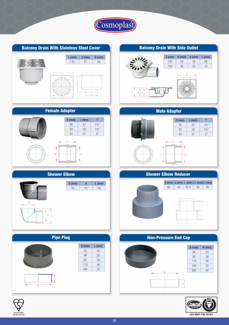
Balcony Drain With Side Outlet
Z (mm) D (mm) d (mm) L (mm)
100 56 50 68
150 56 50 70
L D d
Z
Balcony Drain With Stainless Steel Cover
L (mm) Z (mm) D (mm)
110 77 56
26
Non-Pressure End Cap
D (mm) H (mm)
110 30
82 28
56 23
160 32
200 40D
H
Pipe Plug
L
D
D (mm) L (mm)
43 20
56 25
82 35
110 40
160 50
TL
L
Male Adapter
D (mm) L (mm) T
36 47 1¼”
43 52 1½”
43 57 2”
Female Adapter
D (mm) L (mm) T
36 47 1¼”
43 52 1½”
43 57 2”
D T
L
Shower Elbow
D (mm) d L (mm)
43 1½” 56
D
d
L
Shower Elbow Reducer
L (mm) L1 (mm) L2 (mm)
52.5
d (mm)
43
D (mm)
56 25 25
27
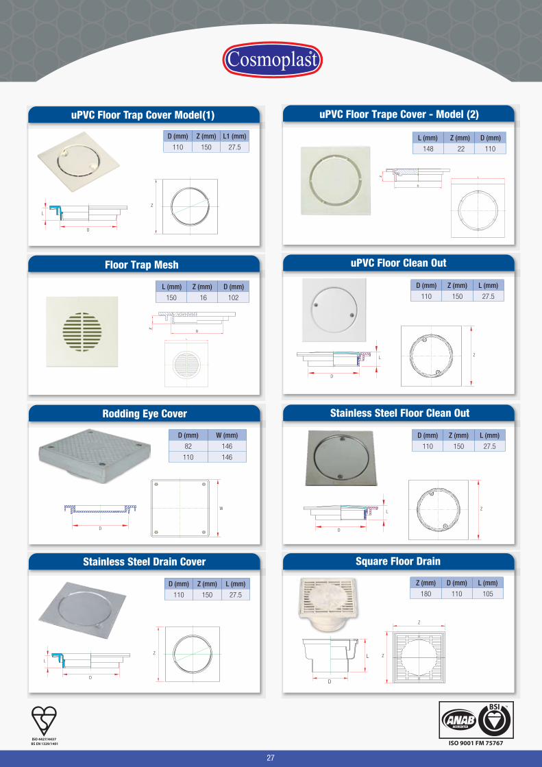
Square Floor Drain
Z (mm) D (mm) L (mm)
180 110 105
Z
Z
D
L
Rodding Eye Cover
D (mm) W (mm)
82 146
110 146
W
D
Stainless Steel Drain Cover
D (mm) Z (mm) L (mm)
110 150 27.5
D
L
Z
uPVC Floor Clean Out
D (mm) Z (mm) L (mm)
110 150 27.5
ZL
D
Floor Trap Mesh
L
D
Z
L (mm) Z (mm) D (mm)
150 16 102
uPVC Floor Trape Cover - Model (2)
Z
D
L
L (mm) Z (mm) D (mm)
148 22 110
Stainless Steel Floor Clean Out
D (mm) Z (mm) L (mm)
110 150 27.5
ZL
D
uPVC Floor Trap Cover Model(1)
D (mm) Z (mm) L1 (mm)
110 150 27.5
D
L
Z
28
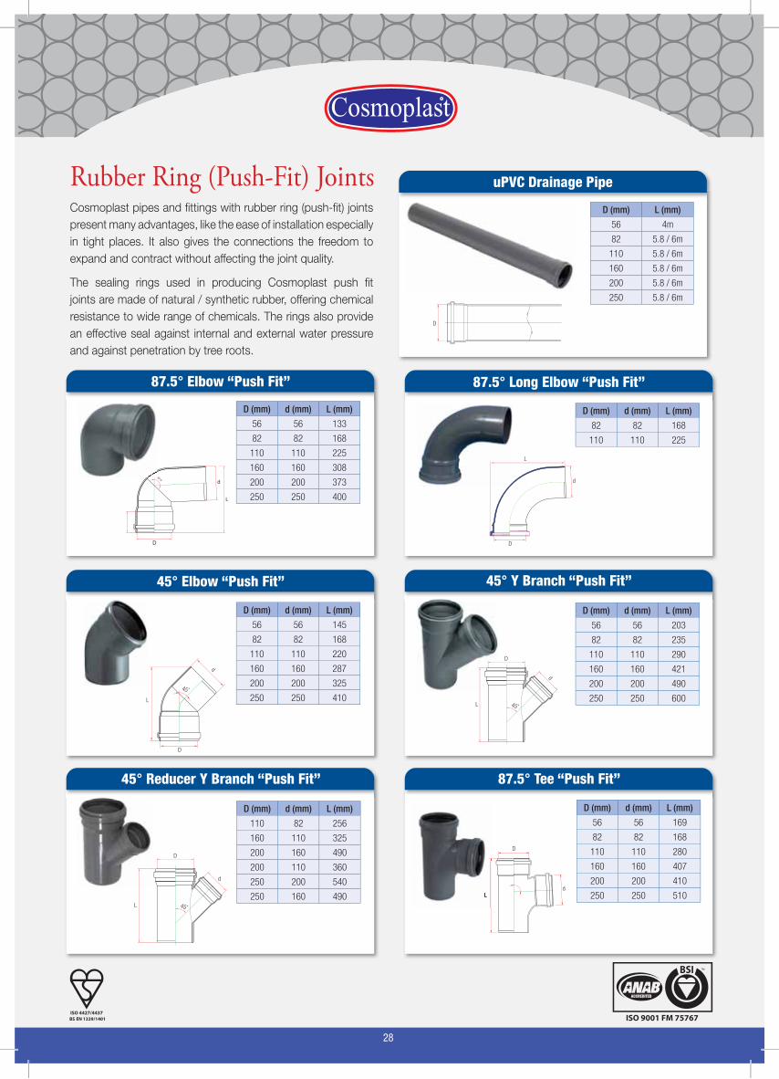
Cosmoplast pipes and fittings with rubber ring (push-fit) joints
present many advantages, like the ease of installation especially
in tight places. It also gives the connections the freedom to
expand and contract without affecting the joint quality.
The sealing rings used in producing Cosmoplast push fit
joints are made of natural / synthetic rubber, offering chemical
resistance to wide range of chemicals. The rings also provide
an effective seal against internal and external water pressure
and against penetration by tree roots.
Rubber Ring (Push-Fit) Joints
D (mm) d (mm) L (mm)
56 56 133
82 82 168
110 110 225
160 160 308
200 200 373
250 250 400
87.5° Elbow “Push Fit”
87.5˚
D
d
L
D (mm) d (mm) L (mm)
56 56 145
82 82 168
110 110 220
160 160 287
200 200 325
250 250 410
45° Elbow “Push Fit”
d
45˚
L
D
D (mm) d (mm) L (mm)
56 56 203
82 82 235
110 110 290
160 160 421
200 200 490
250 250 600
45° Y Branch “Push Fit”
D
d
45˚L
D (mm) d (mm) L (mm)
110 82 256
160 110 325
200 160 490
200 110 360
250 200 540
250 160 490
45° Reducer Y Branch “Push Fit”
D
d
45˚L
D (mm) d (mm) L (mm)
82 82 168
110 110 225
87.5° Long Elbow “Push Fit”
L
d
D
87.5° Tee “Push Fit”
D (mm) d (mm) L (mm)
56 56 169
82 82 168
110 110 280
160 160 407
200 200 410
250 250 510
D
Ld
D (mm) L (mm)
56 4m
82 5.8 / 6m
110 5.8 / 6m
160 5.8 / 6m
200 5.8 / 6m
250 5.8 / 6m
D
uPVC Drainage Pipe
29
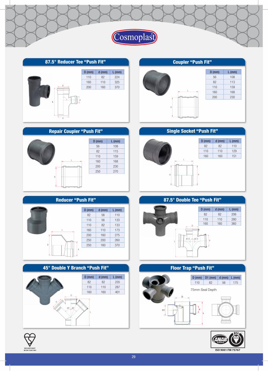
Coupler “Push Fit”
D (mm) L (mm)
56 108
82 113
110 159
160 168
200 230
Repair Coupler “Push Fit”
D (mm) L (mm)
56 108
82 115
110 159
160 168
200 230
250 270
D
L
Single Socket “Push Fit”
D (mm) d (mm) L (mm)
82 82 110
110 110 129
160 160 151
D
L
d
87.5° Reducer Tee “Push Fit”
D (mm) d (mm) L (mm)
110 82 224
160 110 325
200 160 370D
L
d
d
Reducer “Push Fit”
D (mm) d (mm) L (mm)
82 56 110
110 56 133
110 82 133
160 110 173
200 160 275
250 200 260
250 160 370D
d
L
87.5° Double Tee “Push Fit”
D (mm) d (mm) L (mm)
82 82 206
110 110 280160 160 360
D
L87.5˚ 87.5˚
d
45° Double Y Branch “Push Fit”
D (mm) d (mm) L (mm)
82 82 235
110 110 287
160 160 401D
L
45˚ 45˚
d
Floor Trap “Push Fit”
D (mm) D1 (mm) d (mm) L (mm)
110 82 56 175
75mm Seal Depth
D
LdD1
D
L
30
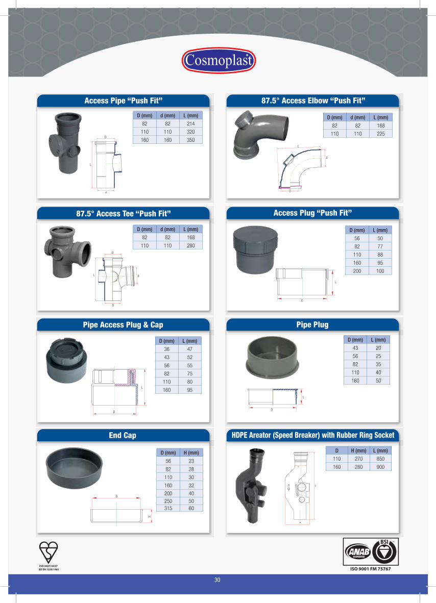
87.5° Access Tee “Push Fit”
D (mm) d (mm) L (mm)
82 82 168
110 110 280
d
D
L
D
Access Pipe “Push Fit”
D (mm) d (mm) L (mm)
82 82 214
110 110 320
160 160 350D
L
d
Access Plug “Push Fit”
D (mm) L (mm)
56 50
82 77
110 88
160 95
200 100
D
L
87.5° Access Elbow “Push Fit”
D (mm) d (mm) L (mm)
82 82 168
110 110 225
d
D
L
HDPE Areator (Speed Breaker) with Rubber Ring Socket
D H (mm) L (mm)
110 270 850
160 280 900
D (mm) L (mm)
36 47
43 52
56 55
82 75
110 80
160 95
Pipe Access Plug & Cap
D
L
End Cap
D
H
D (mm) H (mm)
110 30
82 28
56 23
160 32
200 40250 50315 60
Pipe Plug
L
D
D (mm) L (mm)
43 20
56 25
82 35
110 40
160 50
31
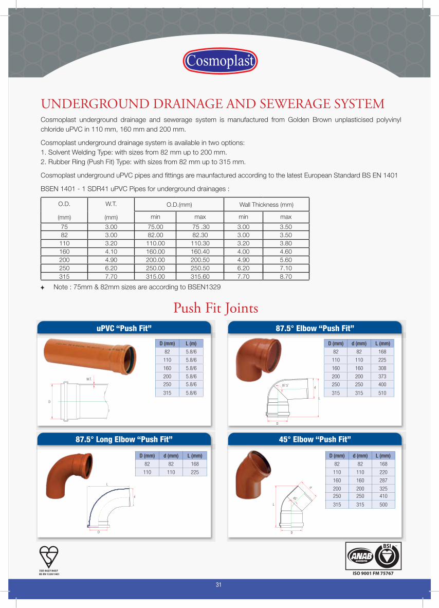
D (mm) L (m)
82 5.8/6
110 5.8/6
160 5.8/6
200 5.8/6
315 5.8/6
250 5.8/6
D (mm) d (mm) L (mm)
82 82 168
110 110 225
uPVC “Push Fit” 87.5° Elbow “Push Fit”
45° Elbow “Push Fit”87.5° Long Elbow “Push Fit”
D
W.T.
D
L
d87.5˚
L
d
D
d
45˚
L
D
D (mm) d (mm) L (mm)
82 82 168
110 110 225
160 160 308
200 200 373
315 315 510
250 250 400
D (mm) d (mm) L (mm)
82 82 168
110 110 220
160 160 287
200 200 325
250 250 410315 315 500
250 250 410
Push Fit Joints
Cosmoplast underground drainage and sewerage system is manufactured from Golden Brown unplasticised polyvinyl chloride uPVC in 110 mm, 160 mm and 200 mm.
Cosmoplast underground drainage system is available in two options:1. Solvent Welding Type: with sizes from 82 mm up to 200 mm.2. Rubber Ring (Push Fit) Type: with sizes from 82 mm up to 315 mm.
Cosmoplast underground uPVC pipes and fittings are maunfactured according to the latest European Standard BS EN 1401
BSEN 1401 - 1 SDR41 uPVC Pipes for underground drainages :
O.D.
(mm)
W.T.
(mm)
O.D.(mm) Wall Thickness (mm)
min max min max
82 3.00 82.00 82.30 3.00 3.5075 3.00 75.00 75 .30 3.00 3.50
110 3.20 110.00 110.30 3.20 3.80160 4.10 160.00 160.40 4.00 4.60200 4.90 200.00 200.50 4.90 5.60250 6.20 250.00 250.50 6.20 7.10315 7.70 315.00 315.60 7.70 8.70
Note : 75mm & 82mm sizes are according to BSEN1329
UNDERGROUND DRAINAGE AND SEWERAGE SYSTEM
32
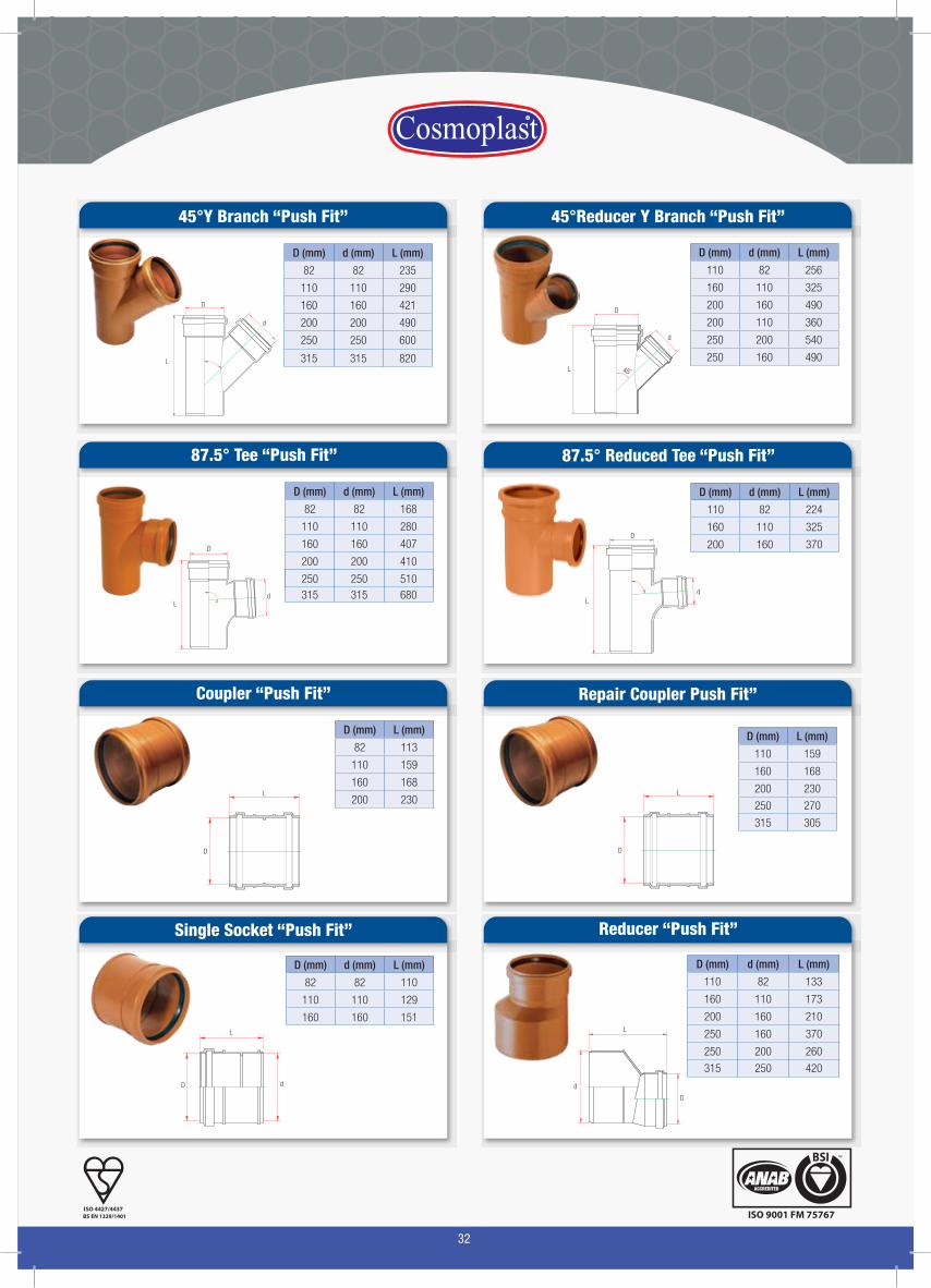
45°Y Branch “Push Fit” 45°Reducer Y Branch “Push Fit”
D
d
L
D
d
45˚L
Coupler “Push Fit”
D (mm) L (mm)
82 113
110 159
160 168
200 230
Repair Coupler Push Fit”
D (mm) L (mm)
110 159
160 168
200 230
315 305
250 270
D
L
Single Socket “Push Fit”
D (mm) d (mm) L (mm)
82 82 110
110 110 129
160 160 151
D
L
d
87.5° Tee “Push Fit”
D
Ld
87.5° Reduced Tee “Push Fit”
D
Ld
Reducer “Push Fit”
D (mm) d (mm) L (mm)
110 82 133
160 110 173
200 160 210
250 160 370
250 200 260
315 250 420
D
d
L
D (mm) d (mm) L (mm)
82 82 235
110 110 290
160 160 421
200 200 490
250 250 600
315 315 820
D (mm) d (mm) L (mm)
110 82 256
160 110 325
200 160 490
200 110 360
250 200 540
250 160 490
D (mm) d (mm) L (mm)
82 82 168
110 110 280
160 160 407
200 200 410
250 250 510315 315 680
D (mm) d (mm) L (mm)
110 82 224
160 110 325
200 160 370
D
L

33
Access Pipe “Push Fit”
D (mm) d (mm) L (mm)
82 82 214
110 110 320
160 160 350D
L
d
45° Double Y Branch “Push Fit”
D
L
45˚ 45˚
d
87.5° Double Tee “Push Fit”
D
L87.5˚ 87.5˚
d
D (mm) d (mm) L (mm)
82 82 235
110 110 287
160 160 401
D (mm) d (mm) L (mm)
82 82 206
110 110 280
End Cap
D (mm) H (mm)
110 30
82 28
200 40200 40
250 50
315 60
160 32
87.5º Access Elbow “Push Fit”
D (mm) d (mm) L (mm)
82 82 168
110 110 225
d
D
L
D
H
87.5º Access Tee “Push Fit”
D (mm) d (mm) L (mm)
82 82 168
110 110 280
d
D
L
Access Plug “Push Fit”
D (mm) L (mm)
82 80
110 87
160 87
200 95
D
L
Pipe Plug
L
D
D (mm) L (mm)
82 35
110 40
160 50
34
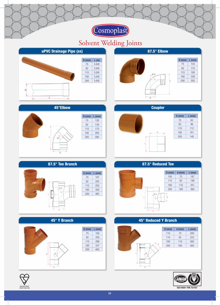
Solvent Welding Joints
D (mm) L (m)
82 5.8/6
75 5.8/6
110 5.8/6
160 5.8/6
200 5.8/6
D (mm) L (mm)
82 170
13375
110 190
160 329
200 305
D
L
uPVC Drainage Pipe (ss)
D
L
87.5̊
87.5° Elbow
D (mm) L (mm)
82 96
75 83
110 112
160 161
200 140
Coupler
L
D
45°Elbow
D (mm) L (mm)
82 139
75 128
110 170
160 269
200 290L 45˚
D
D (mm) L (mm)
82 205
75 192
110 268
160 337
200 400
D (mm) d (mm) L (mm)
110 82 223
110 75 209
160 110 380
200 160 400
L
D
45˚ L
D
d
45˚
45° Y Branch 45° Reduced Y Branch
D (mm) d (mm) L (mm)
110 82 199
100 75 187
160 110 251
200 160 360
87.5° Reduced Tee
D
87.5˚
L d
87.5° Tee Branch
D (mm) L (mm)
82 205
75 167
110 250
160 358
200 365L
D
87.5˚
35
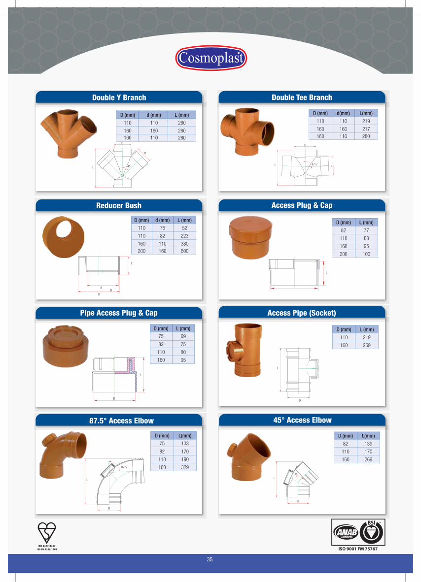
D (mm) d (mm) L (mm)
110 82 223
110 75 52
160 110 380200 160 600
Reducer Bush
L
D
d
Double Y Branch
L
D
45˚
d
D (mm) d(mm) L(mm)
110 110 219
160 160 217160 110 280
L d
D
87.5˚
Access Plug & Cap
D (mm) L (mm)
82 77
110 88
160 95
200 100
Double Tee Branch
L
d (mm) L (mm)
110 260
160
D (mm)
110
160 260280110160
D
D (mm) L (mm)
82 75
75 69
110 80
160 95
Pipe Access Plug & Cap
D
L
Access Pipe (Socket)
D (mm) L (mm)
110 219
160 259
L
D
D (mm) L(mm)
82 170
75 133
110 190
160 329
87.5° Access Elbow
L
D
87.5˚
45° Access Elbow
D (mm) L(mm)
82 139
110 170
160 269
L
D
45˚

36
V-Type P Trap Solvent
D1 (mm) D2 (mm)
110
H1 (mm)
245
H (mm)
216
L (mm)
303110
Bottle Trap
D (mm) d (mm) L (mm)
180 110 290
D
dL
D (mm) L(mm)
82 205
110 250
160 358
87.5° Access Door Tee
D
L
87.5˚
Gully Trap
D (mm) d (mm) L (mm) H (mm)
180 110 290 150
Ld
D
H
d
P Trap
D (mm) d (mm) L (mm)
110 110 290
D
d
L
Bottle Gully Trap
D (mm) D1(mm) d (mm) d1(mm) L (mm)
180 110 110 50 270
L
D
D1 dd1
V-Type P Trap Rubber
H1 (mm)
245
H (mm)
216
L (mm)
303
D1 (mm) D2 (mm)
110 110
Square Hopper Granting
L
L
H
D
H1
L(mm) H (mm) H1(mm)D (mm)
164 98 25110
37
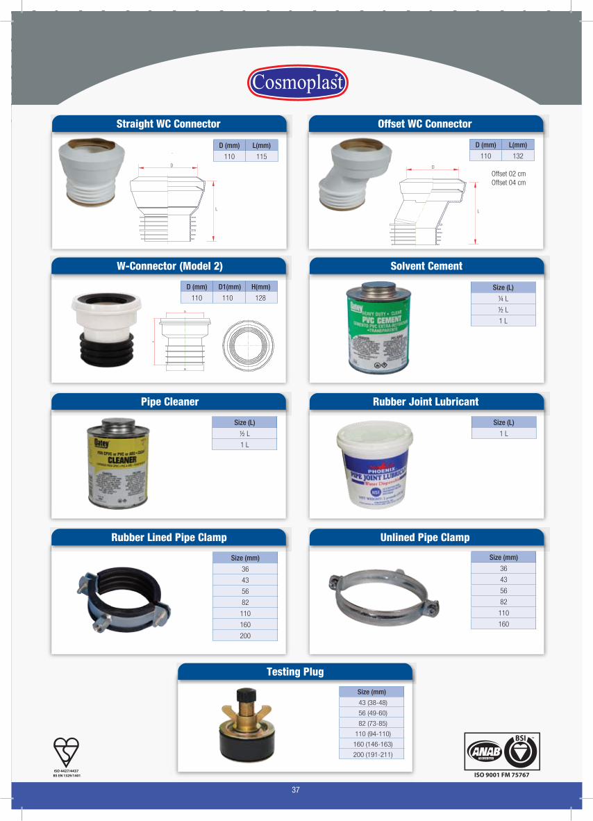
Straight WC Connector
D (mm) L(mm)
110 115D
L
Offset WC Connector
D (mm) L(mm)
110 132D
L
Offset 02 cmOffset 04 cm
W-Connector (Model 2)
Pipe Cleaner
Rubber Lined Pipe Clamp
D (mm) D1(mm)
110 110
H(mm)
128
Solvent Cement
Size (L)
½ L
1 L
Rubber Joint Lubricant
Size (mm)
36
43
56
82
110
160
200
Testing Plug
Size (mm)
Unlined Pipe Clamp
Size (L)
¼ L
½ L
1 L
Size (L)
1 L
Size (mm)
36
43
56
82
110
160
43 (38-48)
56 (49-60)
82 (73-85)
110 (94-110)
160 (146-163)
200 (191-211)
38
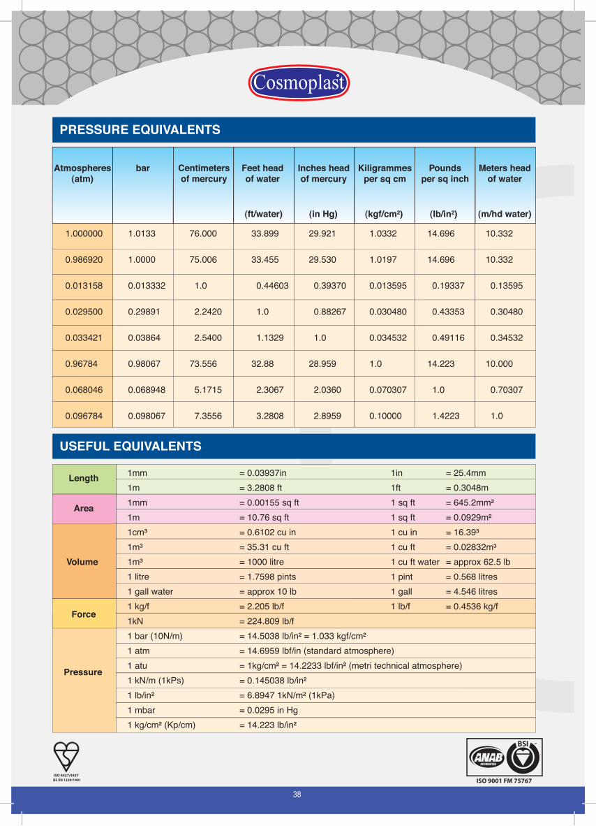
Atmospheres(atm)
bar Centimetersof mercury
Feet headof water
Inches headof mercury
Kiligrammesper sq cm
Poundsper sq inch
Meters headof water
(ft/water) (in Hg) (kgf/cm²) (lb/in²) (m/hd water)
1.000000 1.0133 76.000 33.899 29.921 1.0332 14.696 10.332
0.986920 1.0000 75.006 33.455 29.530 1.0197 14.696 10.332
0.013158 0.013332 1.0 0.44603 0.39370 0.013595 0.19337 0.13595
0.029500 0.29891 2.2420 1.0 0.88267 0.030480 0.43353 0.30480
0.033421 0.03864 2.5400 1.1329 1.0 0.034532 0.49116 0.34532
0.96784 0.98067 73.556 32.88 28.959 1.0 14.223 10.000
0.068046 0.068948 5.1715 2.3067 2.0360 0.070307 1.0 0.70307
0.096784 0.098067 7.3556 3.2808 2.8959 0.10000 1.4223 1.0
PRESSURE EQUIVALENTS
USEFUL EQUIVALENTS1mm = 0.03937in 1in = 25.4mm1m = 3.2808 ft 1ft = 0.3048m1mm = 0.00155 sq ft 1 sq ft = 645.2mm²1m = 10.76 sq ft 1 sq ft = 0.0929m²1cm³ = 0.6102 cu in 1 cu in = 16.39³1m³ = 35.31 cu ft 1 cu ft = 0.02832m³1m³ = 1000 litre 1 cu ft water = approx 62.5 lb1 litre = 1.7598 pints 1 pint = 0.568 litres1 gall water = approx 10 lb 1 gall = 4.546 litres1 kg/f = 2.205 lb/f 1 lb/f = 0.4536 kg/f1kN = 224.809 lb/f1 bar (10N/m) = 14.5038 lb/in² = 1.033 kgf/cm²1 atm = 14.6959 lbf/in (standard atmosphere)1 atu = 1kg/cm² = 14.2233 lbf/in² (metri technical atmosphere)1 kN/m (1kPs) = 0.145038 lb/in²1 lb/in² = 6.8947 1kN/m² (1kPa)1 mbar = 0.0295 in Hg1 kg/cm² (Kp/cm) = 14.223 lb/in²
Area
Length
Volume
Force
Pressure
39
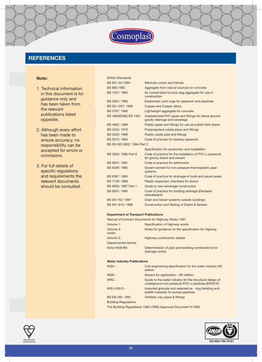
REFERENCES
Note:
1. Technical information in this document is for guidance only and has been taken from the relevant publications listed opposite.
2. Although every effort has been made to ensure accuracy, no responsibility can be accepted for errors or ommisions.
3. For full details of specific regulations and requirements the relevent documents should be consulted.
British Standards
BS EN 124:1994 Manhole covers and frames
BS 882:1992 Aggregate from natural sources for concrete
BS 1047: 1983 Air cooled blast furnace slag aggregate for use in construction
BS 2924: 1990 Elastomeric joint rings for pipework and pipelines
BS EN 1057: 1996 Copper and Copper alloys
BS 3797: 1990 Lightweight aggregate for concrete
BS 4660(2000) EN 1401 Unplasticised PVC pipes and fittings for below ground gravity drainage and sewerage
BS 4962: 1989 Plastic pipes and fittings for use as subfoil field drains
BS 5254: 1976 Polypropylene waste pipes and fittings
BS 5255: 1989 Plastic waste pipe and fittings
BS 5572: 1994 Code of practise for sanitary pipework
BS EN ISO 9002: 1994 Part 2
Specification for production and installation
BS 5955: 1980 Part 6 Code of practice for the installation of PVC-u pipework for gravity drains and sewers
BS 6031: 1981 Code of practice for earthworks
BS 6209: 1982 Sovent cement for non-pressure thermoplastic pipe systems
BS 6367: 1983 Code of practice for drainage of roofs and paved areas
BS 7158: 1989 Plastic inspection chambers for drains
BS 8005: 1987 Part 1 Guide to new sewerage construction
BS 8301: 1985 Code of practice for building drainage (Declared obscelesant)
BS EN 752: 1997 Drain and Sewer systems outside buildings
BS EN 1610: 1998 Construction and Testing of Drains & Sewers
Department of Transport Publications
Manual of Contract Documents for Highway Works 1991
Volume 1: Specification of Highway works
Volume 2: Notes for guidance on the specification for highway works
Volume 3: Highway construction details
Departmental Advice
Note HA40/89: Determination of pipe and bedding combinations for drainage works
Water industry Publications
WSA - Civil engineering specification for the water industry 4th edition
WSA - Sewers for application - 4th edition
WRC - Guide to the water industry for the structural design ofunderground non-pressure PVC-u pipelines (ER201E)
WIS 4.08.01- Imported granular and selected as - dug bedding andsidefill materials for buried pipelines
BS EN 295: 1991 Vitrifiedy clay pipes & fittings
Building Regulations
The Building Regulations 1985 (1990) Approved Document H:1992
40