
UNIVERSITI TEKNIKAL MALAYSIA MELAKA
DESIGN IMPROVEMENT OF SOLAR GRASS CUTTER USING DFMA METHODOLOGY
Thesis submitted in accordance with requirement of the Universiti Teknikal Malaysia
Melaka (UTeM) for the Bachelor Degree of Manufacturing Engineering
(Manufacturing Design) with Honours.
by
ISMAIL BIN RASHID
FACULTY OF MANUFACTURING ENGINEERING
2011


i
ABSTRACT
This project describe about the implementation of redesign the solar grass cutter by
using the application of Design for Manufacturing and Assembly (DFMA)
methodology. The scope based on the existing solar grass cutter and the appropriate
of DFMA methodology. The method used for gaining the data is from the resembled
the existing solar grass cutter. From the data achieved, it can be classified into
several categories to be studied. Data would be analyzed by using Lucas Hull method
to verify the design efficiency, handling ratio and fitting ratio to achieve. The tools
that used is TeamSET software. The new proposed design of solar grass cutter
drawn by using SolidWorks software based on TeamSET result achieved. Result
shown that the design efficiency for new design solar grass cutter obtained better
percentage rather than the existing design. From the study, the total part, handling
ratio, fitting ratio and cost of existing design is reduced. Eventually, the improvement
of new design solar grass cutter finally will be able to meet user requirements and
satisfactions.

ii
ABSTRAK
Projek ini menghuraikan tentang pelaksanaan dalam mereka bentuk semula mesin
pemotong rumput solar dengan menggunakan aplikasi perisian DFMA (Design for
Manufacturing and Assembly). Skop projek adalah memfokuskan mesin pemotong
rumput solar yang sedia ada dan sesuai dengan kaedah DFMA. Kaedah yang di
gunakan untuk memperoleh data ialah dengan menganalisis mesin pemotong rumput
solar yang sedia ada. Data yang diperoleh dapat diklasifikasikan ke dalam beberapa
kategori untuk dikaji. Data dianalisis dengan menggunakan kaedah Lucas Hull bagi
menentukan kecekapan reka bentuk, nisbah pengendalian dan nisbah perhimpunan
sebagai pencapaian objektif projek. Perkakas perisian yang digunakan ialah perisian
TeamSET. Reka bentuk mesin pemotong rumput baru di lukis dengan menggunakan
perisian SolidWorks berdasarkan hasil yang didapati dari analisis TeamSET.
Keputusan yang di peroleh membuktikan yang kecekapan reka bentuk untuk mesin
pemotong rumput yang direka bentuk semula memperolehi peratusan lebih baik
daripada reka bentuk yang sedia ada. Daripada kajian itu, jumlah bahagian, nisbah
pengendalian, nisbah perhimpunan dan kos reka bentuk juga dapat dikurangkan.
Akhirnya, peningkatan mesin pemotong rumput baru ini dapat memenuhi keperluan
dan kepuasan pengguna.

iii
DEDICATION
To my beloved Mum
Rahimah Binti Abdul Rahman
To my beloved wife
Hasaniah Binti Yahya
For the rest of the families, my brothers and sisters,
Thanks for your encouragement, support and motivation.

iv
ACKNOWLEDGEMENTS
Bismillahirrahmaanirrahiim…
Alhamdullilah, grateful to Allah for giving me the strength to finish this final year
project completely beside gaining valuable experiences and knowledge throughout
completing this thesis, this experiences and knowledge may assist me to develop my
personal skill in the future.
Special thanks are addressed to my supervisor, En Taufik for his guidance, advices, idea,
and his patience to me in accomplishing this project, a special debt of gratitude towards
him. To my beloved mother, brothers and sisters, and my wife, thank you so much.
Without their continue support and encouragement, I could not have gone further than
where I have. Not forgetting En. Zolkarnain Bin Marjom and my friends for their help,
co-operation, opinion and advice.
Lastly to the names that I forgot to mention, you know who you are, thank you so much
from the bottom of my heart.
May Allah repay all your kindness…

v
TABLE OF CONTENTS
ABSTRACT i
ABSTRAK ii
DEDICATION iii
ACKNOWLEDGEMENT iv
TABLE OF CONTENTS v
LIST OF TABLE viii
LIST OF FIGURE ix
LIST OF EQUATION x
LIST OF ABBREVIATIONS xi
CHAPTER 1 INTRODUCTION
1.1 Project background 1
1.2 Problem statements 2
1.3 Objectives of the project 3
1.4 Scopes of the project 3
CHAPTER 2 LTERATURE REVIEW
2.1 Introduction 4
2.2 Designs for Assembly (DFA) Overview 5
2.3 Drives for DFA Implementation 6
2.3.1 Global market changes 6
2.3.2 Consequences of component oriented design 7
2.4 Assembly Methods and Processes 8
2.4.1 Manual assembly 8
2.4.2 Automated Assembly 9
2.4.2.1 Automatic /Dedicated Assembly 9
2.4.2.2 Robotic /Flexible Assembly 10

vi
2.5 Lucas Hull DFA Method 10
2.6 Designs for Assembly (DFA) Guideline 14
2.7 Solar cell (Photovoltaic, PV) 15
2.14.1 History of Photovoltaic (PV) 16
2.14.2 Environmental Benefits of PV 17
CHAPTER 3 METHODOLOGY
3.1 Introduction 18
3.2 Methodology 18
3.3 Project Planning 19
3.3.1 Gantt Chart 20
3.4 Project Flowchart 21
3.4.1 The detailed explanations of the flowchart 23
CHAPTER 4 RESULT AND ANALYSIS
4.1 Introduction of analysis 28
4.2 Draw design using SolidWork software 29
4.2.1 Detail drawing of existing design 29
4.2.2 Detail drawing of redesign 30
4.3 Analysis using TeamSET software 31
4.3.1 DFA analysis for existing design 32
4.3.1.1 Flow chart of existing design 33
4.3.1.2 Flow chart of handling part existing design 34
4.3.1.3 Flow chart of main part existing design 35
4.3.1.4 TeamSET analysis for existing design 36
4.3.2 DFA analysis for redesign 37
4.3.2.1 Flow chart of redesign 38
4.3.2.2 Flow chart of handling part redesign 38
4.3.2.3 Flow chart of main part redesigns 39
4.3.2.4 TeamSET analysis for existing design 40

vii
4.4 Material and process selection 41
4.4.1 Container box 41
4.4.2 Strap 42
4.4.3 Blade 43
CHAPTER 5 DISCUSSION
5.1 Comparison of existing design with redesign 44
5.2 Safeguard for prevent from heating 46
CHAPTER 5 CONCLUSION AND FUTURE WORKS
6.1 Conclusion 47
6.2 Future works 48
REFERENCES 49
APPENDICES
Appendix A 51
Appendix B 54

viii
LIST OF TABLES
3.1 : Gantt Chart 20
3.2 : Example of table for nine dimensions of quality 27
4.1 : Quantity list of existing design 31
4.2 : Quantity list of a redesign 37
5.1 : Comparison of existing design with redesign 45

ix
LIST OF FIGURE
2.1 : Design Changes vs. Cost 6
2.2 : Cost comparison between different assembly methods relative with
volume of production 8
2.3 : Annual production volume for each type assembled 9
2.4 : Example of assembly sequence flow chart 11
2.5 : Nine questions for consideration on an example part 12
2.6 : Photovoltaic cell 16
3.1 : Flowchart for research methodology 22
3.2 : Exploded drawing existing product 24
3.3 : Detailed drawing existing product 24
4.1 : View of existing design 29
4.2 : View of redesign 30
4.3 : A flow chart of existing design 33
4.4 : A flow chart of handling part existing design 34
4.5 : A flow chart of main part existing design 35
4.6 : TeamSET analysis for existing design 36
4.7 : A flow chart of redesign 38
4.8 : A flow chart of handling part redesign 38
4.9 : A flow chart of main part redesign 39
4.10 : TeamSET analysis for redesign 40
4.11 : Drawing of container box 41
4.12 : Drawing of strap 42
4.13 : Drawing of blade 43
5.1 : Part for safeguard 46
6.1 : Shows the comparison between existing product and redesign 47

x
LIST OF EQUATION
1 : Design Efficiency 12
2 : Handling Ratio 14
3 : Assembly Ratio 14

xi
LIST OF ABBREVIATIONS
DFMA Design of Manufacturing and Assembly
DFA Design for Assembly
PSM Projek Sarjana Muda
SPC Stastical Process Control

1
CHAPTER 1 INTRODUCTION
1.1 Project Background
Grass cutter machine can easily found everywhere in hardware shop with reasonable
price. The grass cutter machine is requiring for some private residence in housing area
was having landscape in the house. The modern design creates the machine grass cutter
which is safer than ever before to be used in private residential.
Today, there are many machine grass cutter in the market. But it still can be improved or
redesign especially from ergonomic point of view. It is because some of the
characteristics are not suitable for objective use in area industry like blade shape and
material of blade, economic factor like currently was use the fuel, movement limited for
used electricity, and not flexible. Therefore, this is a new proposal idea of a machine
grass cutter where it was applied the ergonomics design concept which is cover the
ergonomic aspects like safety, user friendly in term of functional, cost and the specially
was used the solar energy was generated by solar panel as a source of power
replacement the petrol like currently grass cutter machine at the market.
This project will apply the Design for Manufacturing and Assembly (DFMA)
methodology. Therefore, one of the DFMA approaches, Lucas Hull DFA are
implemented in order to improved the product development process and reduces
manufacturing cost. It is because a lot of cost involved in manufacturing and assembly
of a product.
2
A significant part of this cost can be attributed to the labour intensive activities
associated with assembly. Therefore that approach is used by the design team in
simplifying the product structure, reduce assembly cost and time and to quantify
improvements. This report is more focus to one type of landscape appliance which is a
Solar Grass Cutter.
1.2 Problem Statements
Lately, we usually see the grass cutter machine was used at the housing park and
residence bungalow. The commercial area like industry area, we usually see the
manually and conversional method was used grass cutter machine was use the fuel as
source power. The costing of maintenance for fuel was increase by the current price of
fuel was increase at same time. Otherwise, many accidents happened to operator was
used the machine like the blade of machine was regardless from machine. Thus, this
case study project will be focusing on grass machine cutter was use alternative source of
power like solar energy to replacement the fuel as the source of power. In addition, the
modification will be do to the blade use the friendly user material and not hazard to the
operator of the machine. One more thing is the price of the machine was currently at
market too expensive, hopefully with the redesign was use software TeamSET will be
reduce the part not necessary and will reduce the production cost and same time the
price of the machine will be more cheapest compare current market.

3
1.3 Objectives of the Project:
The objectives of this project are:
1. To study design parameter of solar grass cutter
2. To analyze the solar grass cutter machine using DFMA methodology
3. To design the solar grass cutter machine.
1.4 Scopes of Project:
It is a project limitation or project area where this project will be focusing on which is to
ensure that the project is not run out and still in project scopes. Below are the scopes of
the project:-
(a) Analyze and review the existing product in order to identify the advantages and
disadvantages of the current design of a machine grass cutter and propose the new
design based on design efficiency by use Lucas Hull (Team set) software.
(b) Implement the Lucas Hull software (Team set) to improve the design efficiency
(c) The software solid work will be use to design the product.

4
CHAPTER 2 LITERATURE REVIEW
2.1 Introduction
A literature review is one of the research methods to review the previous history in order
to get the idea, project concept development, project methods and so on. A literature
review is one of the mechanisms for our references to grab and get more knowledge
about some research or product or what else that has done by previous researcher. It
viewed the scientific process and concept based on their experimental. Usually, it comes
out like journal, books, article and so on. The component of literature review is the
actual research where they use the fact and logical concept that nobody can argue their
research.
This chapter will explain the design for assembly and manufacturing (DFMA) concept
and the drives for industries to implement DFMA concept. They are global market
changes and consequences of component oriented design. However, one of the DFMA
method, Lucas -Hull only mentioned in this chapter and is implemented throughout this
project.

5
2.2 Designs for Assembly (DFA) Overview
Design for assembly (DFA) is an approach to minimize assembly cost and time by
reducing the number of parts or simplify the product. The application of DFA usually
brings consequences to product quality and reliability improvement and reduction of
production part and inventory. Those consequences are also the factors of reduced
assembly cost. According to Chan and Filippo (2005), DFA can be defined as; A
product design improvement processes for convenient and low cost assembly that
focusing on functionality and assembly.
There are three best known and also the most well documented DFA method. They are
the Boothroyd –Dewhurst System, The Lucas DFA Method and the Hitachi
Assemilability Evaluation Method (AEM). In general, the designer is guided through the
analyses, which are presented in a series of assessment charts. The charts are based on
empirical data gathered by knowledge engineering exercise with industrial expert and
organised in an easy –to-use worksheet format.
During the evaluation, the designer is required to ass‘s component functionality, form,
manufacturing processes and assembly characteristic using value extracted from the
charts according to component properties. These numbers are then compiled in tabular
format, and calculation performed. In this way, the designer is able to quantify the
suitability of the design (www.eng.hull.ac.uk).The Lucas DFA methodology has been
chosen for use within this project because of available facility within UTeM and there
are some circumstances found within the other two.

6
2.3 Drives for DFA Implementation
There are identified two major factors that lead the industries or the companies started to
implement DFA.They are global market changes and requirement of proper or
convenient assembly in order to raise the rate of delivery to customer and also to
improve product development and cost.
2.3.1 Global market changes
The competitive nature of the international market place has led to short product
lifecycles and reduced price margins. Therefore, methods to improve the product
development processes and reduce cost required. It is because a lot of cost involved in
manufacturing and assembly of a product. A significant part of this cost can be attributed
to the labour intensive activities associated with the assembly. Therefore DFA method is
used by the design team in simplifying the product structure, reduce assembly cost and
time and to quantify improvements.(www.eng.hull.ac.uk).
Figure 2.1: Design Changes vs. Cost (www.eng.hull.ac.uk).

7
2.3.2 Consequences of component oriented design
There has been a trend towards automated assembly in order to reduce labour costs.
However, the potential benefits of automated assembly are limited by the need for
flexibility and the ability to respond to product changes and short production runs
whereby the most effective from of assembly is often manual assembly. Therefore,
automated product assembly process is not necessarily the solution for reducing product
development costs. (www.eng.hull.ac.uk).
In fact, the design process is the key to reduce product development costs. As shown in
Figure 2.1, the overall product development costs are determined during the design stage
which is approximately 80%. The high assembly costs are often due to an unnecessarily
large number of components in the product and the complex manufacturing and
assembly processes that are required due to the design of inappropriate component
interfaces. Studies have shown that often, product is still designed with at least 50%
excess of parts and greater assembly content than is necessary (www.eng.hull.ac.uk).
The poor design which caused by the designers who designed product according to their
intuition highly contributed to assembly problem is still prevalent in many industries.
Traditionally or the over the wall approach, different engineering departments perform
design, planning and manufacture of the product with no integration or feedback and so
assembly problem are identified only at the later stages of production .In order to reduce
lead times and product cost effectively, manufacturing and assembly issues must be
detected and considered during design or also known as concurrent engineering
approach. This required the introduction of assembly –oriented design so that product
development and assembly planning can be performed simultaneously rather than
consecutively as referred to www.eng.hull.ac.uk(2003).

8
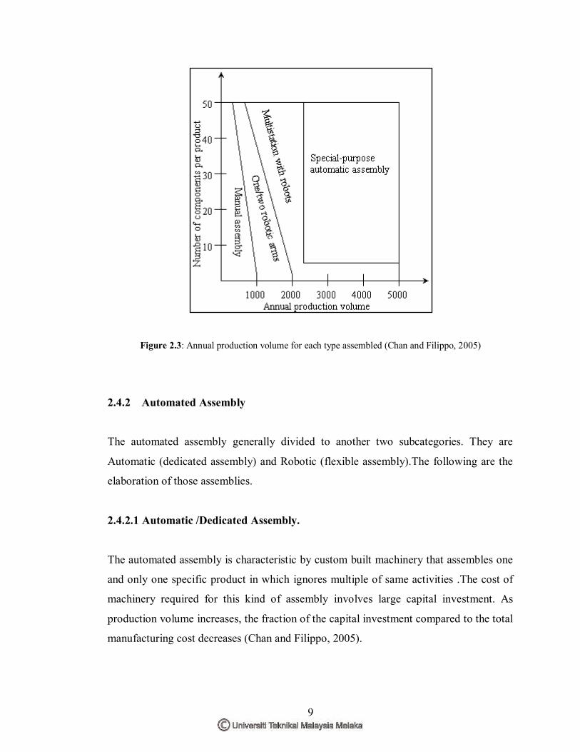
2.4 Assembly Methods and Processes
Mostly there are two types of basic assembly processes in industries today. They are
those performed manually (human) and those performed by mechanism (automated).The
comparison between assembly methods are shown in Figure 2.2 and Figure 2.3.
Figure 2.2: Cost comparison between different assembly methods relative with volume of production.
(Chan and Filippo , 2005)
2.4.1 Manual assembly
In manual assembly, the parts are transferred from a workbench to another where the
workers manually assemble the components into full product or each person responsible
for the assembly of only a small portion of the complete unit. In doing this kind of
assembly, tools such as screwdriver or any other assembly tools are essential in aiding
the workers doing assembly. This kind of assembly is the most flexible and adaptable
among the assembly methods. However, there are limit to the production secondary
operation analysis may required on certain parts volume, and labour cost which include
benefits, cases of workers compensation due to injury, overhead for maintaining a clean,
and healthy environment are higher according,(Chan and Filippo,2005).
9
Figure 2.3: Annual production volume for each type assembled (Chan and Filippo, 2005)
2.4.2 Automated Assembly
The automated assembly generally divided to another two subcategories. They are
Automatic (dedicated assembly) and Robotic (flexible assembly).The following are the
elaboration of those assemblies.
2.4.2.1 Automatic /Dedicated Assembly.
The automated assembly is characteristic by custom built machinery that assembles one
and only one specific product in which ignores multiple of same activities .The cost of
machinery required for this kind of assembly involves large capital investment. As
production volume increases, the fraction of the capital investment compared to the total
manufacturing cost decreases (Chan and Filippo, 2005).


