Download - Touchscreen Operation

CoolMasterNet
User Manual
Touchscreen Operation
Document Number: 1.1.2
Contact information: https://coolautomation.com/support/

CoolMasterNet Overview
UM Version 1.1.2 ii CoolMasterNet
Table of Contents
1. Overview .............................................................................................................................. 1
1.1 What You Can Do From the CoolMasterNet Touchscreen ............................... 1
2. The CoolMasterNet Touchscreen ....................................................................................... 2
2.1 General Layout of the Main Screen .................................................................. 2
2.2 Screen Functionality and Indications ................................................................ 2
2.2.1 HVAC Line Details .............................................................................. 2
2.2.2 Each Indoor unit is represented by a single row on the screen .......... 3
2.2.3 VRF Error Message Display ............................................................... 3
2.2.4 Screen Indications .............................................................................. 3
3. Operational Functions ........................................................................................................ 6
3.1 Basic Operational Controls ............................................................................... 6
3.1.1 To Turn a Single Indoor Unit On/Off ................................................... 6
3.1.2 To Change Fan Speed and Temperature Set Point ........................... 6
3.1.3 To Change the MODE setting ............................................................. 7
3.2 Lock and Temperature Limitation Settings ....................................................... 9
3.2.1 Lock Functionality ............................................................................... 9
3.2.2 Temperature Limit Functionality ....................................................... 10
4. CoolMasterNet Settings .................................................................................................... 11
4.1 Configuration settings ..................................................................................... 11
4.2 Network Settings ............................................................................................ 13
4.3 HVAC Lines .................................................................................................... 14
4.3.1 To Reconfigure the Device to a Different HVAC Line ....................... 14
4.3.2 HVAC Line Special Functions ........................................................... 17
4.4 BMS Settings .................................................................................................. 18
4.4.1 Virtual Addresses (VA) ..................................................................... 18
Appendix ................................................................................................................................. 20
Support .................................................................................................................................... 21

CoolMasterNet Overview
UM Version 1.1.2 iii CoolMasterNet
Revision History
Version Number
Date Author/Owner Description of Change
1.0 19/8/2019 Preliminary CoolMasterNet User Manual
1.1 17/02/2021 February 2021 UM update
1.1.2 17/03/2021 March 2021 UM update
Acronyms and Abbreviations
Acronym Literal Translation
BMS Building Management System
CMN CoolMasterNet
DHCP Dynamic Host Configuration Protocol
ETH Ethernet
HVAC Heating Ventilation and Air Conditioning
MAC Media Access Control

CoolMasterNet Overview
UM Version 1.1 1 CoolMasterNet
1. Overview
This user manual provides the touchscreen operation instructions necessary for the proper use of the CoolMasterNet.
CoolMasterNet provides automation integrators, facilities managers, service providers, and HVAC professionals with the ability to control, monitor, service, and manage any VRF system through the creation of a universal communication channel between the HVAC and automation systems.
CoolMasterNet enables VRF HVAC connectivity to:
• CoolAutomation suite of applications
• Any Home & Building Automation systems
• Smart Home Devices
1.1 What You Can Do From the CoolMasterNet Touchscreen
• Control and monitoring of all connected VRF Indoor units.
• Perform control operations (increase/decrease temperature setpoint, fan setting, mode setting (heat, cool), turn unit On/Off, view room temperature, select desired lock functionality, and select temperature limits for cool and heat separately.
• Reconfigure the device for different HVAC brands.
• Turn On or Off all detected Indoor units at once (All On/All Off capability) or turn them Off or On individually.
• View Indoor unit mode as indicated by the unit’s background color on the screen and its set point temperature.
• View device’s settings and status: firmware version, Serial Number/MAC address, IP address, active local network connection and cloud connectivity status.
• Change the device settings (Configuration, Network, and BMS settings).

CoolMasterNet The CoolMasterNet Touchscreen
UM Version 1.1 2 CoolMasterNet
2. The CoolMasterNet Touchscreen
2.1 General Layout of the Main Screen
When the device is connected, the following screen is displayed. After a successful installation, all connected units are automatically detected, and the Main screen displays the detected Indoor units and their status.
2.2 Screen Functionality and Indications
2.2.1 HVAC Line Details
As described on the top row of the above image, the Active HVAC line is displayed on the left
side of the screen —circle with white fill and black font— and inactive lines on the right side of
the screen —circles with black fill and white font. The active line’s manufacturer abbreviation is
displayed inside the white circle on the left —DK on the above screen (for a list of available
manufacturers and respective abbreviations refer to the Appendix). The number to the right of
the manufacturer indicates the number of detected units. Daikin (DK) specific cases have two
numbers: one represents groups and the second the number of detected units.
To change device settings, tap the Gear icon on the left and follow the instructions on the
CoolMasterNet Settings chapter.
All HVAC lines can be turned On or Off by toggling the switch to the right of the Gear icon or
individually by toggling the HVAC line’s switch. Use the Scrollbar on the right to scroll through
available lines.
Active HVAC Line. Groups / Detected Units
Settings
Set Point temperature indication
Connected Indoor unit with its address.
Background color indicates the unit’s current
mode
Inactive HVAC Lines
All Units On/Off
Scrollbar
Unit Operation Button (Unit can be turned On/Off directly from the Main screen)
Open Unit to Perform Control Operations
Firmware Version
Serial Number MAC address
Cloud Connectivity Status
Active Local
Network Connection
IP address

CoolMasterNet The CoolMasterNet Touchscreen
UM Version 1.1 3 CoolMasterNet
2.2.2 Each Indoor unit is represented by a single row on the screen
The Indoor unit’s mode is reflected by the background color of its respective row:
• Violet - unit in Fan mode
• Red – unit in Error state. The error code is indicated on the circle to the left
• Blue – unit in Cool mode
• Purple - unit in Auto mode
• Green - unit in Dry mode
• Light brown/orange - unit in Heat mode
• Grey - unit Off
2.2.3 VRF Error Message Display
When there is an error/malfunction in the VRF system, it is displayed on the CoolMasterNet.
When an Indoor unit is in error, the Indoor unit’s row on the Main screen is displayed in red and the original HVAC vendor’s error code is displayed on the left side of the row (see image below). The user should contact the HVAC Technical Support indicating the displayed code.
2.2.4 Screen Indications
On the lower part of the Main screen, five indications are displayed from left to right:
• Firmware Version
• Serial Number/MAC Address
• IP Address
• Active Local Network Connection
• Cloud Connectivity Status
Firmware Version
Serial Number MAC address
Cloud Connectivity Status
Active Local
Network Connection
IP address
HVAC system error code

CoolMasterNet The CoolMasterNet Touchscreen
UM Version 1.1 4 CoolMasterNet
CoolMasterNet maintains permanent connection with the CoolRemote cloud server once TCP/IP networking with internet access is established. The CoolRemote connection status is displayed on the LCD screen as a cloud icon on the bottom right-hand corner of the screen.
IP Address
The IP Address can be either set automatically or manually. By default, DHCP is enabled. To change, tap the Settings button on the Main screen and select Network Settings. For automatic setting, simply turn On DHCP. To set manually, turn DHCP Off and select IP by tapping its > button. Follow the instructions on Section 4.2 Network Settings.
Active Local Network Connection
Available Local Network Connections are described on the following table.
Local Network Connection
Description
ASC ASCII IF Server
MIP ModBus IP
REST REST API
SSDP Control4 protocol
BAC BACnet IP
HDL HDL Buspro over IP
IZone Izone protocol

CoolMasterNet The CoolMasterNet Touchscreen
UM Version 1.1 5 CoolMasterNet
Cloud Connectivity
Cloud Connectivity status indicators:
No cloud icon – No TCP/IP networking
Connected – Communicating
Connected – Idle
Disconnected – communication error code (see following table)
Communication Error Code
Description
-3 Timeout – No reply from the server
-4 A packet was not delivered to the server due to routing problems
-6 Illegal value, port forwarding is disabled or DNS resolution problem
-8 IP duplicate
-9 Trying to connect again, while already connected
-10 Connection was aborted by the server or by one of the nodes/routers on the way to the server (firewall)
-11 Connection was reset by the server or by one of the nodes/routers on the way to the server (firewall)
-12 Connection was closed by server or by one of the nodes/routers on the way to the server (firewall)
-13 Sending packets to the server while not connected
-64 Security reasons

CoolMasterNet Operational Functions
UM Version 1.1 6 CoolMasterNet
3. Operational Functions
3.1 Basic Operational Controls
Basic operational controls like Unit On/Off, Set Temperature, Fan speed and Unit mode can be performed from the main screen by selecting an indoor unit.
3.1.1 To Turn a Single Indoor Unit On/Off
Turning a unit On/Off can be performed directly from CoolMasterNet’s main screen.
3.1.2 To Change Fan Speed and Temperature Set Point
Select the desired indoor unit by tapping the > button to enter the unit and perform other control operations.

CoolMasterNet Operational Functions
UM Version 1.1 7 CoolMasterNet
On the displayed screen you can change the following settings by tapping on the corresponding setting:
• FAN SPEED (options: Low, Medium, High, Top, Auto)
• Temperature Set Point (repeatedly tap the respective arrow to increase or decrease the temperature set point)
• Room Temperature indication (reported by the VRF system)
3.1.3 To Change the MODE setting
Tap the Mode setting to select unit mode (Cool, Heat, Dry, Fan, Auto).
Note: Mode change can only be done for all connected indoor units. It is not available for each individual indoor unit.
Note: Auto and Dry modes are available only in systems that support these modes.
Unit On/Off (Tap to turn off)
Temperature Set Point
MODE setting
FAN setting
Room temperature
CoolMasterNet Operational Functions
UM Version 1.1 8 CoolMasterNet
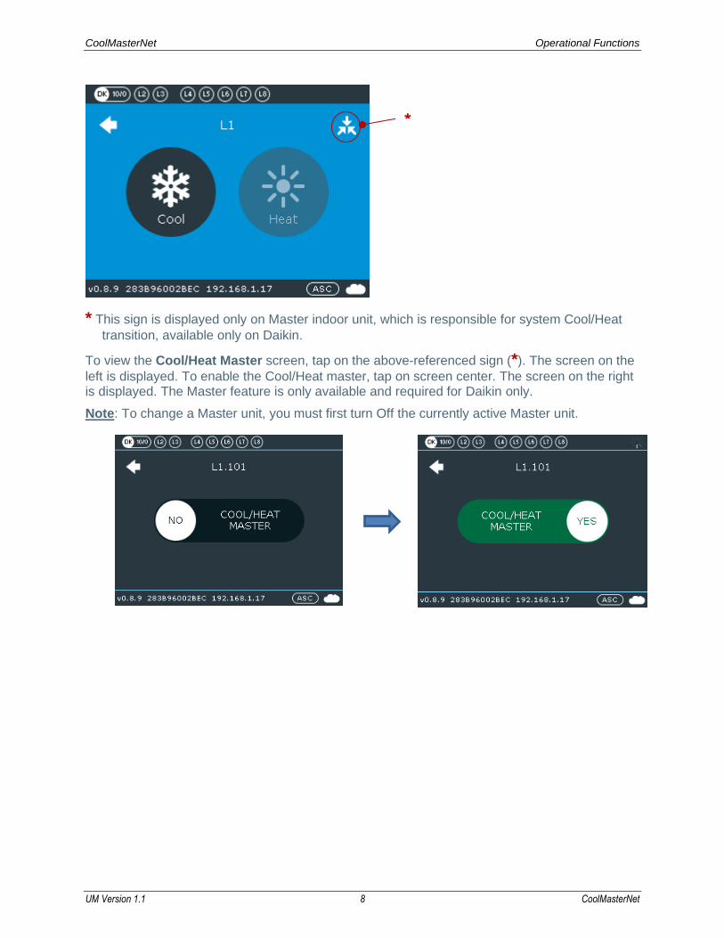
* This sign is displayed only on Master indoor unit, which is responsible for system Cool/Heat
transition, available only on Daikin.
To view the Cool/Heat Master screen, tap on the above-referenced sign (*). The screen on the
left is displayed. To enable the Cool/Heat master, tap on screen center. The screen on the right is displayed. The Master feature is only available and required for Daikin only.
Note: To change a Master unit, you must first turn Off the currently active Master unit.
*

CoolMasterNet Operational Functions
UM Version 1.1 9 CoolMasterNet
3.2 Lock and Temperature Limitation Settings
3.2.1 Lock Functionality
This functionality allows the facility manager to enable/disable the user’s access to turning the unit On or Off, changing the system mode or changing the system’s temperature setting.
Note: The lock functionality applies on all control interfaces (Wired Remote Control, BMS, Home Automation, Coolautomation Apps suite).
For each of these options the Green display indicates the function is disabled and the Red display indicates the function is enabled. When tapping on an option, the option toggles between enabled and disabled.
Available lock options:
• Lock On or Off (Unit On/Off)
• Lock Mode
• Lock Setpoint
To activate tap the Lock icon (see image below).
The following screen is displayed.
Tap the desired lock functions. The selected functions turn red and the other one remains green.
CoolMasterNet Operational Functions
UM Version 1.1 10 CoolMasterNet
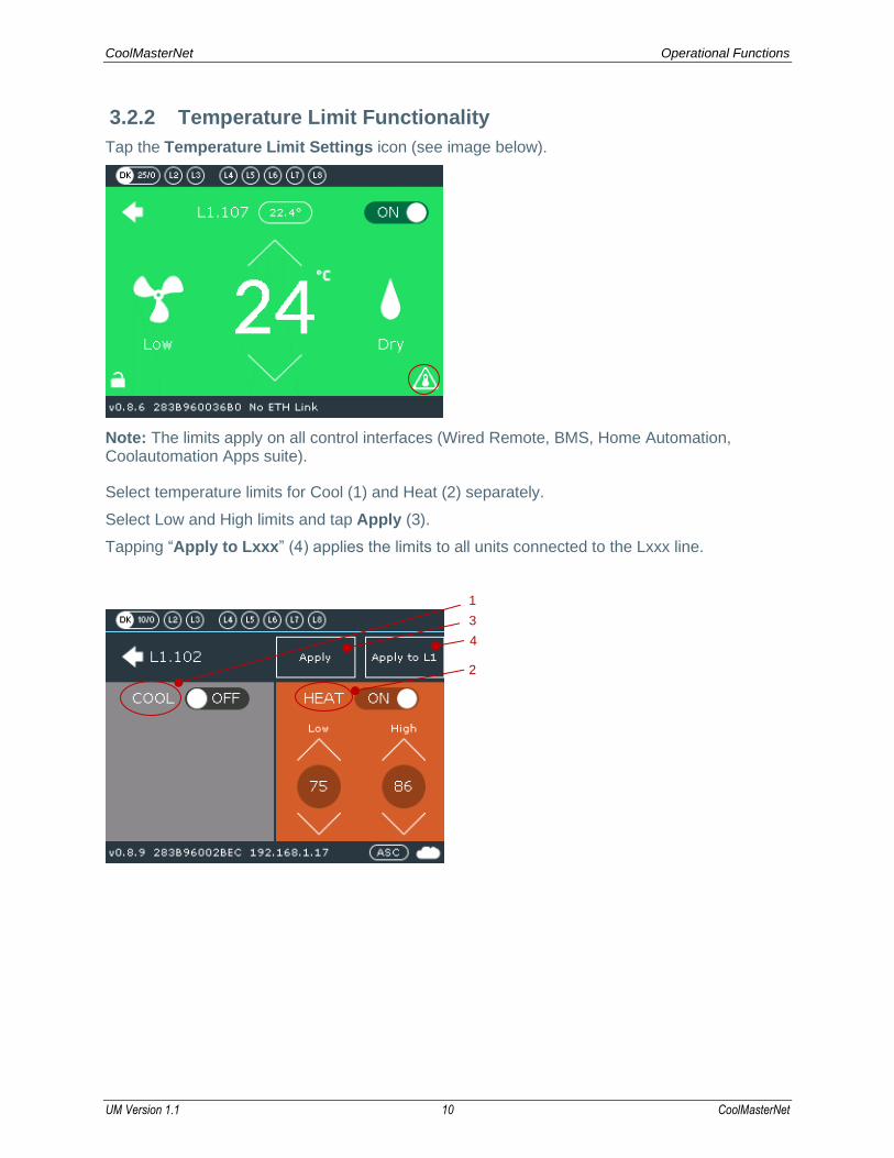
3.2.2 Temperature Limit Functionality
Tap the Temperature Limit Settings icon (see image below).
Note: The limits apply on all control interfaces (Wired Remote, BMS, Home Automation, Coolautomation Apps suite).
Select temperature limits for Cool (1) and Heat (2) separately.
Select Low and High limits and tap Apply (3).
Tapping “Apply to Lxxx” (4) applies the limits to all units connected to the Lxxx line.
3
1
2
4
CoolMasterNet CoolMasterNet Settings
UM Version 1.1 11 CoolMasterNet
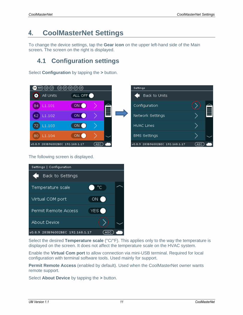
4. CoolMasterNet Settings
To change the device settings, tap the Gear icon on the upper left-hand side of the Main screen. The screen on the right is displayed.
4.1 Configuration settings
Select Configuration by tapping the > button.
The following screen is displayed.
Select the desired Temperature scale (°C/°F). This applies only to the way the temperature is displayed on the screen. It does not affect the temperature scale on the HVAC system.
Enable the Virtual Com port to allow connection via mini-USB terminal. Required for local configuration with terminal software tools. Used mainly for support.
Permit Remote Access (enabled by default). Used when the CoolMasterNet owner wants remote support.
Select About Device by tapping the > button.

CoolMasterNet CoolMasterNet Settings
UM Version 1.1 12 CoolMasterNet
The following screen is displayed. The screen shows if BACnet IP and ModBus IP are enabled/disabled.
To enable BACnet IP please contact CoolAutomation support (https://coolautomation.com/support/#contact)
Modbus IP can be enabled via the BMS Settings.
CoolMasterNet CoolMasterNet Settings
UM Version 1.1 13 CoolMasterNet
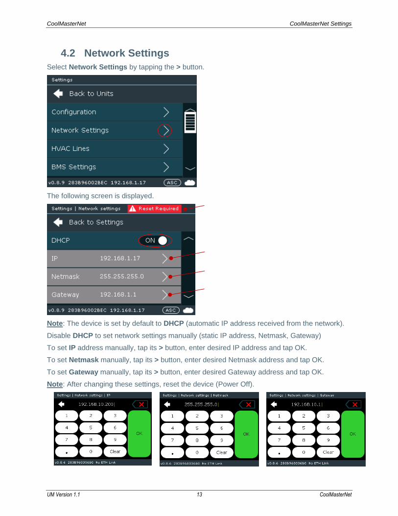
4.2 Network Settings
Select Network Settings by tapping the > button.
The following screen is displayed.
Note: The device is set by default to DHCP (automatic IP address received from the network).
Disable DHCP to set network settings manually (static IP address, Netmask, Gateway)
To set IP address manually, tap its > button, enter desired IP address and tap OK.
To set Netmask manually, tap its > button, enter desired Netmask address and tap OK.
To set Gateway manually, tap its > button, enter desired Gateway address and tap OK.
Note: After changing these settings, reset the device (Power Off).

CoolMasterNet CoolMasterNet Settings
UM Version 1.1 14 CoolMasterNet
4.3 HVAC Lines
Select HVAC Lines by tapping the > button.
4.3.1 To Reconfigure the Device to a Different HVAC Line
1. Tap the Settings button. On the displayed screen tap the HVAC Lines > button. 2. Select the row with the currently active line (DK in our example) and tap the > button. 3. On the HVAC Type row, tap the > button. A screen is displayed showing all the available
HVAC Types (by manufacturer name). 4. Select the desired manufacturer by tapping on the On/Off button. The selected
manufacturer becomes the active HVAC Type, and all other brands are automatically turned Off.
5. Reset the CMN device (power Off). When the device is turned On, the selected manufacturer is displayed as the active HVAC Line.
The device is factory pre-set for required VRF brand.
Lines L1-L2 and L4-L7 are used for specific VRF brands.
CoolMasterNet can be reconfigured from one brand to another from the HVAC Lines menu and
corresponding position of DIP switches, located behind the door on the front, right-hand side of
the device. For DIP switch positions, and list of the brands please refer to the Installation
manual on https://coolautomation.com/support/#products.
CoolMasterNet CoolMasterNet Settings
UM Version 1.1 15 CoolMasterNet
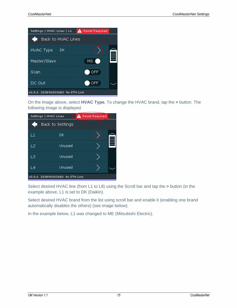
On the image above, select HVAC Type. To change the HVAC brand, tap the > button. The
following image is displayed.
Select desired HVAC line (from L1 to L8) using the Scroll bar and tap the > button (in the
example above, L1 is set to DK (Daikin).
Select desired HVAC brand from the list using scroll bar and enable it (enabling one brand
automatically disables the others) (see image below).
In the example below, L1 was changed to ME (Mitsubishi Electric).
CoolMasterNet CoolMasterNet Settings
UM Version 1.1 16 CoolMasterNet
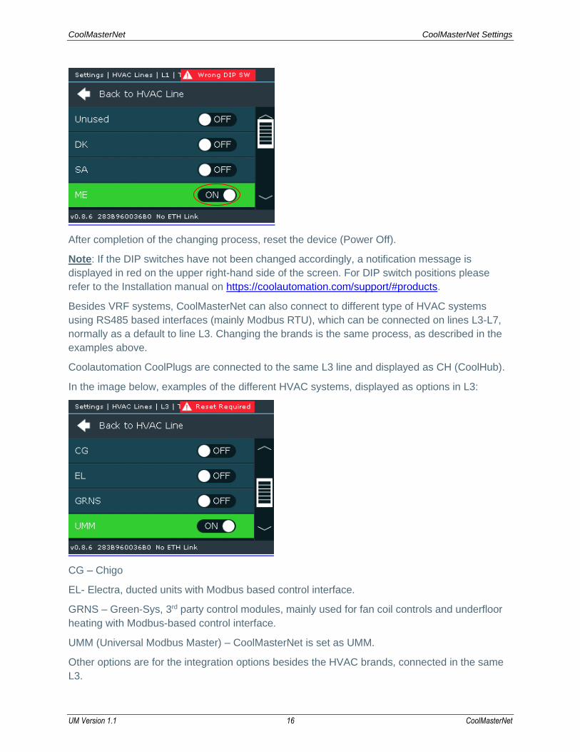
After completion of the changing process, reset the device (Power Off).
Note: If the DIP switches have not been changed accordingly, a notification message is
displayed in red on the upper right-hand side of the screen. For DIP switch positions please
refer to the Installation manual on https://coolautomation.com/support/#products.
Besides VRF systems, CoolMasterNet can also connect to different type of HVAC systems
using RS485 based interfaces (mainly Modbus RTU), which can be connected on lines L3-L7,
normally as a default to line L3. Changing the brands is the same process, as described in the
examples above.
Coolautomation CoolPlugs are connected to the same L3 line and displayed as CH (CoolHub).
In the image below, examples of the different HVAC systems, displayed as options in L3:
CG – Chigo
EL- Electra, ducted units with Modbus based control interface.
GRNS – Green-Sys, 3rd party control modules, mainly used for fan coil controls and underfloor
heating with Modbus-based control interface.
UMM (Universal Modbus Master) – CoolMasterNet is set as UMM.
Other options are for the integration options besides the HVAC brands, connected in the same
L3.

CoolMasterNet CoolMasterNet Settings
UM Version 1.1 17 CoolMasterNet
4.3.2 HVAC Line Special Functions
Set CoolMasterNet as Master/Slave in the VRF network.
By default, CoolMasterNet is set as Master. In some cases, with specific HVAC brands (LG and
Samsung), when original central controller is installed in the project, it should be manually set to
Slave.
Enable the Scan option.
Scanning the HVAC line is an automatic process that autodetects connected indoor units. In
some cases, when CoolMasterNet set to Slave, manual Scan should be disabled. By default,
manual Scan is enabled.
Enable the DC Out option. Required only with Daikin or Mitsubishi Electric NON-VRF systems
with the corresponding DIP switch positions.
Before enabling this function, please consult with Coolautomation tech support
https://coolautomation.com/support#support
Note: After changing these settings, reset the device (Power Off).

CoolMasterNet CoolMasterNet Settings
UM Version 1.1 18 CoolMasterNet
4.4 BMS Settings
From the Main screen, tap the Gear icon. The following screen is displayed.
Select BMS Settings by tapping the > button. The following screen is displayed.
The Modbus IP and Modbus RTU on L3 options should be enabled.
Note: After changing these settings, reset the device (Power Off).
Note: To enable the Modbus RTU on other HVAC Lines (L4-L7), refer to the HVAC Lines settings (Section 4.3.1).
Note: To enable BACnet IP and BACnet MS/TP, contact Coolautomation support.
https://coolautomation.com/support/#contact
4.4.1 Virtual Addresses (VA)
To keep the BMS (BACnet and Modbus) integration process the same for all connected
systems, CoolMasterNet allows unifying all connected indoor units to one type of internal,
normalized, virtual table, where each connected indoor unit is represented as a unified Virtual
Address. Each indoor unit is represented as a table of Modbus/BACnet related objects with
corresponding register type.

CoolMasterNet CoolMasterNet Settings
UM Version 1.1 19 CoolMasterNet
To create the referenced table, scroll to the VA Auto row and tap Run (see image below).
Note: It is particularly important to perform this action after verifying that all indoor units are
connected and properly recognized. Otherwise, after adding a missing indoor unit to the network
and running the VA Auto command again, all VA’s would be overwritten, which may cause an
incorrect integration process from the BMS side.
Note: a missing unit may be entered manually (without causing problems with the addresses)
via the Coolautomation SW tool or with the help of Coolautomation tech support.
After completing VA distribution, reset the device (Power Off).
Select the VA List option to see the distributed VAs list by clicking > button. The following
screen is displayed.
Each indoor unit (e.g., L1.104) is presented in the table with a corresponding VA Address
(0004) and its Base register (00065).
For more details, refer to Modbus and BACnet guidelines on the Coolautomation support page
https://coolautomation.com/support/#integration_guidelines/
CoolMasterNet Appendix
UM Version 1.1 20 CoolMasterNet
Appendix
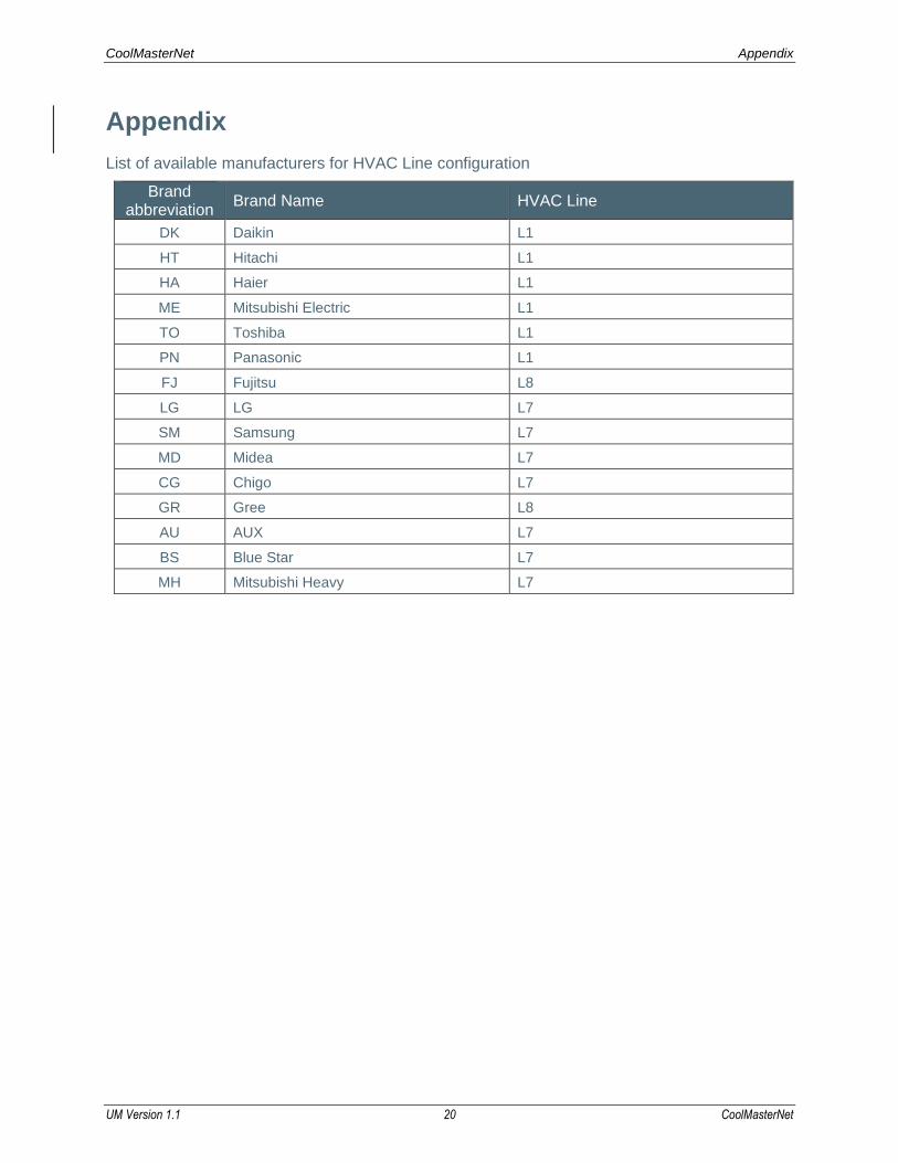
List of available manufacturers for HVAC Line configuration
Brand abbreviation
Brand Name HVAC Line
DK Daikin L1
HT Hitachi L1
HA Haier L1
ME Mitsubishi Electric L1
TO Toshiba L1
PN Panasonic L1
FJ Fujitsu L8
LG LG L7
SM Samsung L7
MD Midea L7
CG Chigo L7
GR Gree L8
AU AUX L7
BS Blue Star L7
MH Mitsubishi Heavy L7

CoolMasterNet Support
UM Version 1.1 21 CoolMasterNet
Support
All documentation can be found on the CoolAutomation website, in the Support Center:
https://coolautomation.com/support
Contacting customer support can be done by opening a service ticket at www.coolautomation.com/support/#contact
Another way of getting help is by scanning the QR code on the back side of the device.
Once scanned from the mobile, it autodetects the type of the product, its serial number, and offers an easy access menu to:
• Online documentation
• Registration to the CoolRemote App
• Opening service ticket for technical support
QR code


