TO DESIGN AND MODIFICATION OF
AUTOMATIC SHOE POLISH
MACHINE
Guided By :-
Prof. Rajeshkumar(Department of Mechanical)
Prepared By :-Daiya Pradip R. (D12ME21)
Chauhan Vipul M. (11ME75)
Swami Harsh R. (11ME68)
Chauhan Vishwas S. (D12ME20)1
Group No :- ME-13 Team ID :-27253
OUTLINE
1. Introduction
2. Literature review
3. Methodology
4. Machine development
5. References
06/04/2015 2
1. INTRODUCTION
• There is a famous proverb “cleanliness is next to godliness”.
The machine which we will design and fabricate implicate this,
called as “automatic shoe polishing machine”
• Most of the industries, hospitals and educational institutions
having most preserved laboratories like computer labs,
instrumentation labs, operational theatre and various
production ,assembly sites in chemical, pharmaceutical
industries etc, have to be free from dust and dirt which would
be carried through shoes of the employees to the work area,
causing untidy environment and also sometimes hazardous to
the working environment.
06/04/2015 3
HISTORY
• The history of shoe polish takes us place to the year before
1900 when people polished their boots with a paste made out
of ash, wax and tallow.
• Later around 1900, this product was improved by using
different liquids and suspended solids like carbon dye, wax,
gum Arabic, turpentine, naphtha and lanolin.
• In medieval period, people used a mixture of soda ash, wax,
tallow and oil to soften and condition the leather and also
make it waterproof. Around 1700s, shine was first added to the
polish.
06/04/2015 4
PROBLEM STATEMENT
Problems created by manual operation ,
• It damages the surface of leather ,if the wire of the brushes is
too hard.
• It decrease the life of the leather shoes . if care not taken in
selecting the right cream.
• It take too much time .
• It is unable to reach the whole surface of the shoe.
• It take too much human effort.
• It’s efficiency is low.
• It is very costly.
06/04/2015 5
PROJECT OBJECTIVE
The objective of this project is listed below,
• Reduce human effort.
• To improve the quality of polishing the shoe
• To reduce the time of operation
• To reduce the material waste
• To improve shining of the shoe
• To combining the operation like cleaning and polishing at one
place
06/04/2015 6
SCOPE OF THE PROJECT
These machine can be used in following field,
• Hospital
• Hostel
• Office
• Home
• Air port etc..
06/04/2015 7
2. LITERATURE REVIEW
Component of shoe polishing machine
1. Shoe polish
2. Shoe brush
3. Power transmitting motor
4. Electronic dispenser
06/04/2015 8
SHOE POLISH
1.Introduction
2. Usage
06/04/2015 9
BRUSHES
• There are two types of brushes used in shoe polishing,
1. BRISTLE-FILLED BRUSHES
2. HORSE HAIR FILLED BRUSHES
06/04/2015 10
MOTOR
• Types of motor
• CHARACTERISTIC OF MOTOR
• MOTOR SELECTION
06/04/2015 11
ELECTRONIC CREAM DISPENSER
• INTRODUCTION
• TYPES OF LIQUID DISPENSER
06/04/2015 12

3. METHODOLOGY
Identify opportunities
Define customer need
Concept generation
Concept selection
Concept testing Detail design
Production ramp up
06/04/2015 13
4. MACHINE DEVELOPEMENT
INTRODUCTION
Accordingly, it is an objective of the project to provide an
apparatus for shining shoes which overcomes the problems
encountered in the conventional art and which can obtain a
desired shoe shining effect similar to when shined by a manual
work or can obtain an excellent shoe shining effect
06/04/2015 14
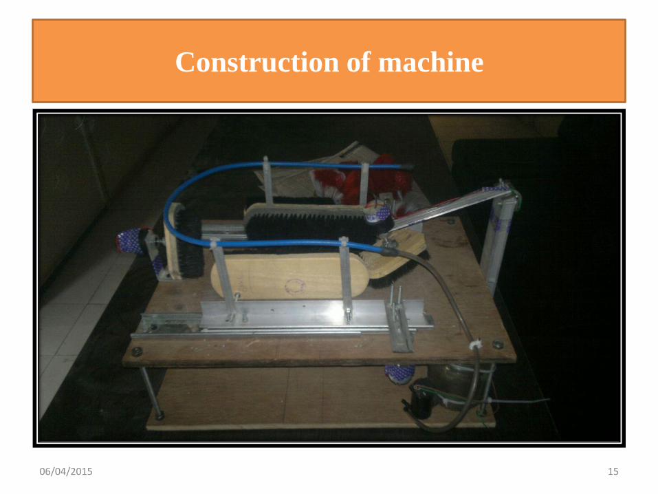
Construction of machine
06/04/2015 15
• Shoe polish machine consist of two layer of board, the lower board
consist of fluid dispensing mechanism and the power supply unit. the
upper layer consist of boot polishing and cleaning mechanism. in
which consist of four brushes made from nylon material .here, we
have used four brushes and we categorized the brushes into,
(1.)Left hand brush
(2.)Right hand brush
(3.)Front side brush
(4.)Back side brush
06/04/2015 16
• Here, all the brushes has co-efficient of friction which lie between
0.68 the left hand brush is placed in the left side of the shoe and right
hand shoe is placed in the right side of the shoe. These two brushes
are placed in the horizontal direction and both are parallel to each
other. The back side brushes is placed in back of the shoe. it's face is
placed toward the back of the shoe. The front brush is placed in the
front of the shoe and its face is toward the front portion of shoe.
• The left and right side brushes is attached with sliding mechanism,
which is able to provide sliding motion to brushes in forward and
reverse motion. The back side brush is attached to the 12v dc motor
with the help of flange, which is able to give rotational motion to the
brush. The front brush is also attached with 12 v dc motor with the
help of flange. This brush is able to moves in up and down direction
because it is further attached with flexible joint which give them
motion in two direction.
06/04/2015 17
• The sliding plate is attached with scotch yoke mechanism, which is
able to generate sliding motion in forward and reverse direction. the
detail about this mechanism is provided further.
• Now ,we will see the dispensing mechanism ,which consist of
following things,
(1.)12 v dc water pump
(2.) fluid container
(3.)fluid dispensing pipe
• The 12v dc water pump is attached with fluid container. The suction
head of water pump is submerged into liquid and the delivery head is
attached with fluid pipe, which is able to deliver fluid with required
pressure. The end side of the pipes is sealed by sealing material for
stopping the leakage of fluid .there are several holes are made at some
specified point for dispensing of fluid to the surface of the shoe.
06/04/2015 18
• The power supply and control unit consist of following things,
(1.)230v ac step-down transformer
(2.)Circuit for converting ac power into dc power
(3.)Two ON-OFF switch for controlling the sliding and rotary motion
of brush
(4.)One ON-OFF switches for controlling the dispension of fluid
(5.)Four 12v dc motor
06/04/2015 19
Working of machine
• This models basically working on scotch yoke mechanism. inscotch yoke mechanism , the rotary motion is converted intosliding motion. This motion gives controlled path is best forour project. Here one 12v motor is used for powertransmitting. This motor is attached with scotch yokemechanism. It convert the rotary motion into sliding motion.There is one sliding plate is used foe sliding motion which isused in domestic application in home. This sliding plate isattached with scotch yoke mechanism with the help of L-shapealuminum angles. On the back side of this angles the shoepolish brush is attached with the help of screw. For the backand front side ,another 12v dc motor is used for rotating thebrushes.
06/04/2015 20
• Now ,when the power is supplied, the first power gone into the step
down transformer and 230v power is converted into 12v ac power.
From them, it is gone through circuit and the ac power is converted
into dc power. This power is supplied to the ON- Off switches which
control the motion of motors and pump.
• Here two switch board is provided, from which the first switches
board consist of two switches which is used for controlling the two
sliding and two rotary motion of the brushes and second switch board
consist of one switches which is used for controlling the flow of fluid.
from the two switches board ,the switchno-1 is used for controlling thr
sliding motion of brush and switch no-2 is used for controlling the
rotary motion of front and back side brushes.
• After switching the power supply ,we just need to ON the switches for
starting the motor and water pump. The brushes start it work
automatically. There is sliding motion of brush create the friction and
it will help to get better shining of the shoe.
06/04/2015 21
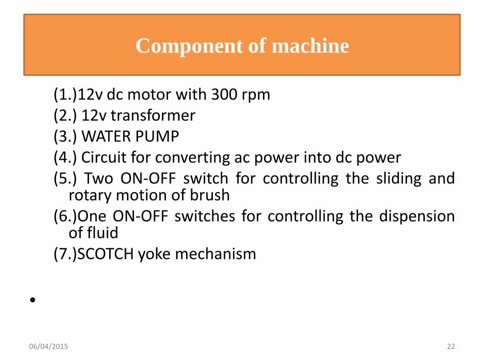
Component of machine
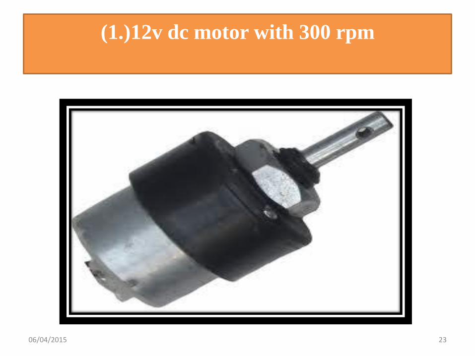
(1.)12v dc motor with 300 rpm(2.) 12v transformer(3.) WATER PUMP(4.) Circuit for converting ac power into dc power(5.) Two ON-OFF switch for controlling the sliding and
rotary motion of brush(6.)One ON-OFF switches for controlling the dispension
of fluid(7.)SCOTCH yoke mechanism
•
06/04/2015 22
• Geared DC motors can be defined as an extension of DC motor which
already had its Insight details demystified here. A geared DC Motor
has a gear assembly attached to the motor. The speed of motor is
counted in terms of rotations of the shaft per minute and is termed as
RPM .The gear assembly helps in increasing the torque and reducing
the speed. Using the correct combination of gears in a gear motor, its
speed can be reduced to any desirable figure. This concept where
gears reduce the speed of the vehicle but increase its torque is known
as gear reduction. This Insight will explore all the minor and major
details that make the gear head and hence the working of geared DC
motor.
06/04/2015 24
Working of the DC Geared Motor
• The DC motor works over a fair range of voltage. The
higher the input voltage more is the RPM (rotations per
minute) of the motor. For example, if the motor works in
the range of 6-12V, it will have the least RPM at 6V and
maximum at 12 V.
06/04/2015 25
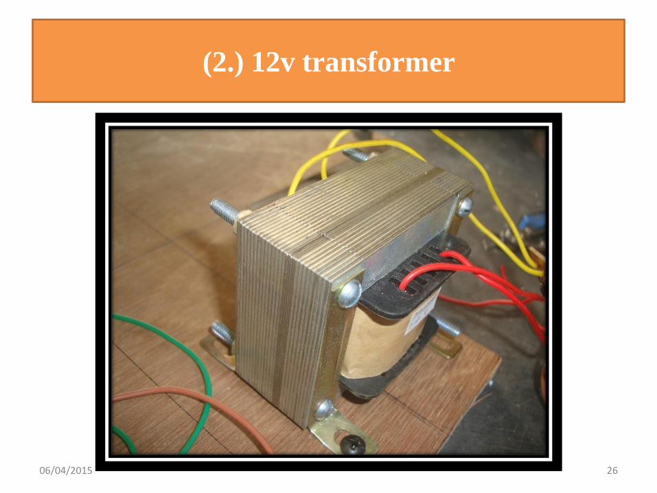
(2.) 12v transformer
06/04/2015 26
• A transformer is a device that transfers electrical energy from one
circuit to another through inductively coupled electrical conductors. A
changing current in the first circuit (the primary) creates a changing
magnetic field; in turn, this magnetic field induces a changing voltage
in the second circuit (the secondary). By adding a load to the
secondary circuit, one can make current flow in the transformer, thus
transferring energy from one circuit to the other. It is the phenomenon
of mutual induction.
• The secondary induced voltage VS, of an ideal transformer, is scaled
from the primary VP by a factor equal to the ratio of the number of
turns of wire in their respective windings:
06/04/2015 27
Transformers are of two types:
• Step up transformer
• Step down transformer
• In power supply we use step down transformer. We apply
220V AC on the primary of step down transformer. This
transformer steps down this voltage to 12V AC.
06/04/2015 28
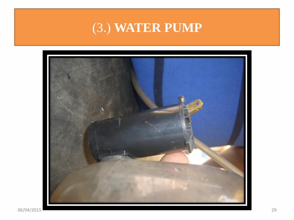
(3.) WATER PUMP
06/04/2015 29
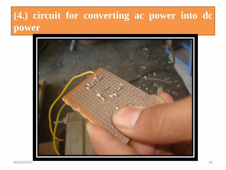
(4.) circuit for converting ac power into dc
power
06/04/2015 30
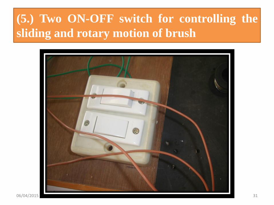
(5.) Two ON-OFF switch for controlling the
sliding and rotary motion of brush
06/04/2015 31
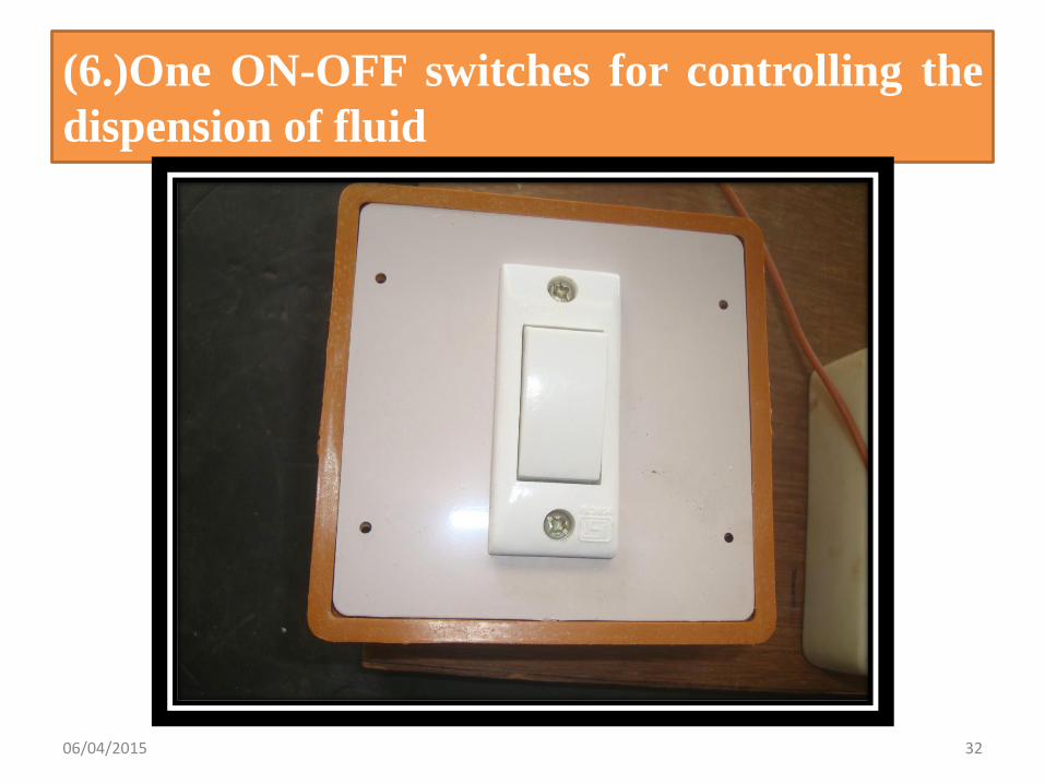
(6.)One ON-OFF switches for controlling the
dispension of fluid
06/04/2015 32
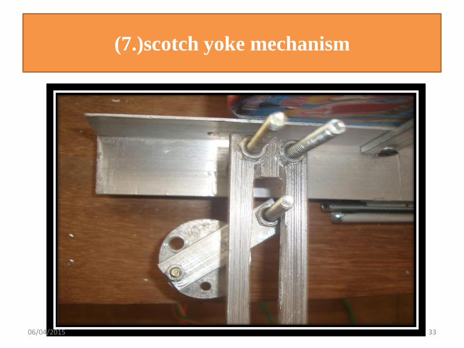
(7.)scotch yoke mechanism
06/04/2015 33
5 .REFERENCES
• www.google.com
• www.scholar.com
• www.shoepassion.com/shoe-brushes.html
• www.kiwicare.com/UK/ShoeCare/ShoeCare.htm
06/04/2015 34

Thank you
06/04/2015 35


