
NAVAL POSTGRADUATE SCHOOL Monterey, California
THESIS
DEVELOPMENT AND CONTROL OF ROBOTIC ARMS FOR THE NAVAL POSTGRADUATE SCHOOL PLANAR
AUTONOMOUS DOCKING SIMULATOR (NPADS)
by
Gary L. Cave
December 2002
Thesis Advisor: Michael G. Spencer Second Reader: Brij N. Agrawal
Approved for public release; distribution is unlimited

THIS PAGE INTENTIONALLY LEFT BLANK
REPORT DOCUMENTATION PAGE Form Approved OMB No. 0704-0188 Public reporting burden for this collection of information is estimated to average 1 hour per response, including the time for reviewing instruction, searching existing data sources, gathering and maintaining the data needed, and completing and reviewing the collection of information. Send comments regarding this burden estimate or any other aspect of this collection of information, including suggestions for reducing this burden, to Washington headquarters Services, Directorate for Information Operations and Reports, 1215 Jefferson Davis Highway, Suite 1204, Arlington, VA 22202-4302, and to the Office of Management and Budget, Paperwork Reduction Project (0704-0188) Washington DC 20503. 1. AGENCY USE ONLY (Leave blank)
2. REPORT DATE December 2002
3. REPORT TYPE AND DATES COVERED Master’s Thesis
4. TITLE AND SUBTITLE: Title (Mix case letters) Development and Control of Robotic Arms for the Naval Postgraduate School Planar Autonomous Docking Simulator (NPADS)
6. AUTHOR(S) Gary L. Cave, LT, USN
5. FUNDING NUMBERS
7. PERFORMING ORGANIZATION NAME(S) AND ADDRESS(ES) Naval Postgraduate School Monterey, CA 93943-5000
8. PERFORMING ORGANIZATION REPORT NUMBER
9. SPONSORING /MONITORING AGENCY NAME(S) AND ADDRESS(ES) N/A
10. SPONSORING/MONITORING AGENCY REPORT NUMBER
11. SUPPLEMENTARY NOTES The views expressed in this thesis are those of the author and do not reflect the official policy or position of the Department of Defense or the U.S. Government. 12a. DISTRIBUTION / AVAILABILITY STATEMENT Approved for public release; distribution is unlimited
12b. DISTRIBUTION CODE A
13. ABSTRACT (maximum 200 words)
This thesis encompasses the development of two robotic arms for integration onto the Naval Postgraduate School (NPS) Planar Autonomous Docking Simulator (NPADS) servicing vehicle. This research effort involved support structure design, fabrication, and construction, off-the-shelf motion control hardware integration, and control algorithm development and testing.
The NPADS system is being built as a test platform for spacecraft docking and capture mechanisms designed for autonomous rendezvous and servicing missions. As with the servicing vehicle, the robotic arms utilize a floatation system on an air-bearing granite table to provide a two-dimensional, drag-free environment. DC brushless servo motors serve as shoulder, elbow, and wrist joints allowing planar motion of the two-link arms. A National Instruments (NI) PXI computer and Motion Control card provide system processing and the software to hardware interface. The NI LabVIEW software suite enabled development of manual control code and autonomous control subroutines compatible with the control software of the NPADS main body. A single, wrist-mounted CCD bullet camera provides visual target acquisition for the robotic arm control system. Testing and analysis were completed in the NPS Satellite Servicing Laboratory on a table-based test harness to facilitate initial design iteration.
15. NUMBER OF PAGES
111
14. SUBJECT TERMS Robotic Arms, Robotics, LabVIEW, Autonomous Docking, Satellite Servicing, Motion Control
16. PRICE CODE
17. SECURITY CLASSIFICATION OF REPORT
Unclassified
18. SECURITY CLASSIFICATION OF THIS PAGE
Unclassified
19. SECURITY CLASSIFICATION OF ABSTRACT
Unclassified
20. LIMITATION OF ABSTRACT
UL
NSN 7540-01-280-5500 Standard Form 298 (Rev. 2-89) Prescribed by ANSI Std. 239-18
i

THIS PAGE INTENTIONALLY LEFT BLANK
ii

Approved for public release; distribution is unlimited
DEVELOPMENT AND CONTROL OF ROBOTIC ARMS FOR THE NAVAL POSTGRADUATE SCHOOL AUTONOMOUS DOCKING SIMULATOR
(NPADS)
Gary L. Cave Lieutenant, United States Navy
B.S., Georgia Institute of Technology, 1996
Submitted in partial fulfillment of the requirements for the degree of
MASTER OF SCIENCE IN ASTRONAUTICAL ENGINEERING
from the
NAVAL POSTGRADUATE SCHOOL December 2002
Author: Gary L. Cave
Approved by: Michael G. Spencer
Thesis Advisor
Brij N. Agrawal Second Reader
Max F. Platzer Chairman, Department of Aeronautics and Astronautics
iii

THIS PAGE INTENTIONALLY LEFT BLANK
iv

ABSTRACT This thesis encompasses the development of two robotic arms for
integration onto the Naval Postgraduate School (NPS) Planar Autonomous Docking
Simulator (NPADS) servicing vehicle. This research effort involved support structure
design, fabrication, and construction, off-the-shelf motion control hardware integration,
and control algorithm development and testing.
The NPADS system is being built as a test platform for spacecraft docking and
capture mechanisms designed for autonomous rendezvous and servicing missions. As
with the servicing vehicle, the robotic arms utilize a floatation system on an air-bearing
granite table to provide a two-dimensional, drag-free environment. DC brushless servo
motors serve as shoulder, elbow, and wrist joints allowing planar motion of the two-link
arms. A National Instruments (NI) PXI computer and Motion Control card provide
system processing and the software to hardware interface. The NI LabVIEW software
suite enabled development of manual control code and autonomous control subroutines
compatible with the control software of the NPADS main body. A single, wrist-mounted
CCD bullet camera provides visual target acquisition for the robotic arm control system.
Testing and analysis were completed in the NPS Satellite Servicing Laboratory on
a table-based test harness to facilitate initial design iteration.
v

THIS PAGE INTENTIONALLY LEFT BLANK
vi
TABLE OF CONTENTS
I. INTRODUCTION....................................................................................................... 1 A. BACKGROUND.............................................................................................. 1
1. On-Orbit Spacecraft Docking ................................................................... 1 2. Space-Based Robotics ................................................................................ 3 3. Naval Postgraduate School (NPS) Satellite Servicing Laboratory ........ 5
B. NPS PLANAR AUTONOMOUS DOCKING SIMULATOR (NPADS).... 5 1. Servicing Vehicle ........................................................................................ 6
a. Hardware ......................................................................................... 7 b. Software ........................................................................................... 7
2. Robotic Arms.............................................................................................. 7 a. Hardware ......................................................................................... 8 b. Software ........................................................................................... 8
C. SCOPE OF THESIS........................................................................................ 8
II. HARDWARE & INTEGRATION .......................................................................... 11 A. OVERVIEW .................................................................................................. 12 B. STRUCTURES.............................................................................................. 14 C. FLOATATION COMPONENTS ................................................................ 15
1. Air Pads..................................................................................................... 15 2. Air Supply System.................................................................................... 15
D. POWER COMPONENTS ............................................................................ 16 E. MOTION CONTROL COMPONENTS..................................................... 17
1. Joint Motors.............................................................................................. 19 2. Amplifiers.................................................................................................. 20 3. Universal Motion Interfaces.................................................................... 20 4. Home Switches.......................................................................................... 21
F. COMPUTER AND ASSOCIATED COMPONENTS ............................... 22 1. Chassis and Controller............................................................................. 22 2. PXI 7344 Motion Controller Card.......................................................... 22 3. PXI 1408 Image Acquisition (IMAQ) Card........................................... 23 4. Test Computer .......................................................................................... 23
G. VISION COMPONENTS............................................................................. 24
III. CONTROL SOFTWARE......................................................................................... 25 A. OVERVIEW .................................................................................................. 25 B. MOTOR TUNING ........................................................................................ 26 C. COMBINED CONTROL ............................................................................. 29
1. Combined Control Code Interface ......................................................... 29 2. Combined Control Code.......................................................................... 30
D. MANUAL CONTROL.................................................................................. 37 3. Manual Control Interface........................................................................ 37 4. Manual Control Code .............................................................................. 37
vii

E. AUTONOMOUS CONTROL ...................................................................... 39 1. Home Finder ............................................................................................. 40
a. Home Finder Interface ................................................................. 40 b. Home Finder Code ........................................................................ 41
2. Commanded Angle................................................................................... 44 a. Commanded Angle Interface ........................................................ 44 b. Commanded Angle Code............................................................... 45
3. Commanded X-Y...................................................................................... 48 a. Commanded X-Y Interface ........................................................... 48 b. Commanded X-Y Code .................................................................. 49
4. Visual Target Acquisition........................................................................ 51 a. Visual Target Acquisition Interface ............................................. 51 b. Visual Target Acquisition Code.................................................... 52
IV. OPERATION AND PERFORMANCE....................................................................... 55 A. ROBOTIC ARM OPERATION .................................................................. 55
1. Robotic Arm Test Setup .......................................................................... 55 2. Robotic Arm Pre-Operation.................................................................... 57 3. Robotic Arm Operation........................................................................... 57 4. Robotic Arm Post-Operation .................................................................. 58 5. Robotic Arm NPADS Integration Setup ................................................ 59
B. ROBOTIC ARM PERFORMANCE........................................................... 61 1. Manual Control Performance ................................................................. 61 2. Home Finder Performance...................................................................... 64 3. Commanded Angle Performance............................................................ 65 4. Commanded X-Y Performance............................................................... 66 5. Visual Target Acquisition Performance................................................. 69
V. SUMMARY AND CONCLUSIONS.............................................................................. 71 A. SUMMARY.................................................................................................... 71 B. FOLLOW-ON RESEARCH ........................................................................ 71
1. Improvements ........................................................................................... 71 2. Future Work ............................................................................................. 72
APPENDIX A: STRUCTURAL DRAWINGS.................................................................. 75
APPENDIX B: WIRING SPECIFICATIONS .................................................................. 81
APPENDIX C: MOTION CONTROLLER SETTINGS ................................................. 87 A. DEFAULT 7344 SETTINGS........................................................................ 87 B. SERVO TUNE GAINS ................................................................................. 90
LIST OF REFERENCES ..................................................................................................... 93
INITIAL DISTRIBUTION LIST ........................................................................................ 95
viii
LIST OF FIGURES
Figure 1 Engineering Test Satellite VII (After: Ref. 1)................................................... 2 Figure 2 Special Purpose Dexterous Manipulator (From: Ref. 2).................................. 3 Figure 3 Robonaut (From: Ref. 3) .................................................................................. 4 Figure 4 NPADS Design Concept ................................................................................... 6 Figure 5 NPADS Servicing Vehicle Concept.................................................................. 6 Figure 6 NPADS Robotic Arm Design Concept (After: Ref. 5) ..................................... 7 Figure 7 NPADS Vehicle with Robotic Arms............................................................... 11 Figure 8 Robotic Arm Attached to Test Harness........................................................... 12 Figure 9 Conceptual Drawing of Robotic Arm Design ................................................. 13 Figure 10 Structural Components.................................................................................... 14 Figure 11 Floatation Components ................................................................................... 16 Figure 12 NPADS Batteries............................................................................................. 16 Figure 13 Power Isolation & Distribution Components .................................................. 17 Figure 14 Motion Control System Layout....................................................................... 18 Figure 15 Harmonic Drive DC Brushless Servo Motor .................................................. 19 Figure 16 B12A6 Servo Amplifier .................................................................................. 20 Figure 17 Universal Motion Interface ............................................................................. 21 Figure 18 Home Switch ................................................................................................... 21 Figure 19 NPADS Onboard Computer............................................................................ 22 Figure 20 Robotic Arm Test Computer ........................................................................... 23 Figure 21 Robotic Arm Bullet Camera............................................................................ 24 Figure 22 Measurement & Automation Explorer Configuration Menu .......................... 27 Figure 23 MAX Default 7344 Setting Axis Configuration Menu................................... 27 Figure 24 MAX Servo Tune Control Loop Page............................................................. 28 Figure 25 NPADS Robotic Arm Manual/Autonomous Controls Front Panel ................ 30 Figure 26 LabVIEW Control Code Diagram – Part 1 of 3.............................................. 31 Figure 27 LabVIEW Control Code Diagram – Part 2 of 3.............................................. 32 Figure 28 LabVIEW Control Code Diagram – Part 3 of 3.............................................. 33 Figure 29 Emergency Stop Routine Code ....................................................................... 34 Figure 30 Initialize Controller Routine Code .................................................................. 34 Figure 31 Switching Mechanism Code............................................................................ 35 Figure 32 Position and Velocity Indicator Code ............................................................. 36 Figure 33 Manual Control Front Panel............................................................................ 37 Figure 34 Manual Control Code ...................................................................................... 38 Figure 35 Joint Operation/Isolation Code........................................................................ 39 Figure 36 Autonomous Control System Block Diagram................................................. 40 Figure 37 Home Finder Trigger with Velocity and Position Indicators.......................... 41 Figure 38 Home Finder Code (2 Frames)........................................................................ 43 Figure 39 Home Finder Code (Final Frame) ................................................................... 44 Figure 40 Angle Command Front Panel.......................................................................... 45 Figure 41 Robotic Arm Angular Coordinate Frame........................................................ 45
ix

Figure 42 Commanded Angle Code (True Inner Case)................................................... 47 Figure 43 Commanded Angle Code (False Inner Case).................................................. 48 Figure 44 X-Y Command Front Panel............................................................................. 48 Figure 45 Robotic Arm X-Y Coordinate Frame.............................................................. 49 Figure 46 Commanded X-Y Code................................................................................... 50 Figure 47 Visual Target Acquisition Front Panel............................................................ 51 Figure 48 Visual Target Acquisition Code...................................................................... 53 Figure 49 Robotic Arm Test Setup.................................................................................. 56 Figure 50 Test Harness Arrangement, Zero Reference Configuration............................ 56 Figure 51 Robotic Arm NPADS Main Body Integration Setup ...................................... 59 Figure 52 Robotic Arm Procedural Components on NPADS Vehicle............................ 60 Figure 53 Manual Control Profile for Shoulder Joint...................................................... 62 Figure 54 Manual Control Profile for Elbow Joint.......................................................... 63 Figure 55 Manual Control Profile for Wrist Joint ........................................................... 63 Figure 56 Home Finder Profile for Shoulder and Elbow Position .................................. 64 Figure 57 Home Finder Profile for Shoulder and Elbow Velocity.................................. 65 Figure 58 Commanded Angle Profile for Shoulder and Elbow ...................................... 66 Figure 59 Commanded X-Y Profile for Wrist Position................................................... 68 Figure 60 Commanded X-Y Profile for Shoulder and Elbow ......................................... 68 Figure 61 Joint Motor Housing Top Plate ....................................................................... 76 Figure 62 Joint Motor Housing Bottom Plate.................................................................. 77 Figure 63 Joint Motor Housing Standoffs (Shoulder, short; Elbow/Wrist, long) ........... 78 Figure 64 Elbow/Wrist Joint Motor Housing Back Plate................................................ 79 Figure 65 Arm Linkage ................................................................................................... 80 Figure 66 AMP Connector Pinouts.................................................................................. 81 Figure 67 MOLEX Connectors Pinouts for Feedback Harnesses ................................... 83 Figure 68 MOLEX Connector for Amplifier Pinout ....................................................... 84 Figure 69 UMI Layout (From: Ref. 6)............................................................................. 85 Figure 70 MAX Default 7344 Settings Definitions......................................................... 87 Figure 71 MAX Step Response Plot................................................................................ 91 Figure 72 MAX Bode Plot............................................................................................... 91 Figure 73 MAX Trajectory Response Plot ...................................................................... 91
x

LIST OF TABLES
Table 1 NPADS Robotic Arm Component Characteristics ......................................... 13 Table 2 Arm Power Distribution Barrier Strip Diagram.............................................. 17 Table 3 Desired Home Positions .................................................................................. 44 Table 4 Robotic Arm Pre-Operation Checklist ............................................................ 57 Table 5 Robotic Arm Post-Operation Checklist........................................................... 58 Table 6 Robotic Arm On-Vehicle Checklist Addendum ............................................. 60 Table 7 Manual Control Code Test Profile .................................................................. 62 Table 8 Commanded Angle Control Code Test Profile ............................................... 66 Table 9 Commanded X-Y Control Code Test Profile.................................................. 67 Table 10 Visual Target Acquisition Code Test Profile (Straight Out)........................... 70 Table 11 Visual Target Acquisition Code Test Profile (Fully Extended Left) .............. 70 Table 12 Motor Connector Pinout.................................................................................. 82 Table 13 Motor Power Cable to Amplifier Harness Pinout ........................................... 82 Table 14 Motor Feedback to UMI/Amplifier Harness Pinout ....................................... 83 Table 15 B12A6L Servo Amplifier Pinout .................................................................... 84 Table 16 UMI Pinout Per Axis....................................................................................... 86 Table 17 Default 7344 Settings ...................................................................................... 88 Table 18 PID Control Gains for NPADS Robotic Arms................................................ 90
xi

THIS PAGE INTENTIONALLY LEFT BLANK
xii

ACKNOWLEDGMENTS The author would like to thank the following people for their invaluable support
in the completion of this thesis:
Dr. Michael Spencer – For rescuing me from a life of simulation,
Dr. Brij Agrawal – For his outstanding sponsorship,
Air Force Research Lab (AFRL) – For their trust and assistance,
LCDR Bob Porter – For his friendship and countless sanity checks,
Mr. Glenn Harrell – For fabrication of the structural components of the arms,
and
Walter Cave – For re-teaching his stubborn son the electronics basics that he refused to
learn growing up.
But, most importantly, I want to thank my wife and girls, Jessica, Kayla, and Corinne, for turning each day into a Beautiful, Sunny Day. Their unending love and support allowed me to complete this step in my life, making it all the more special.
xiii

THIS PAGE INTENTIONALLY LEFT BLANK
xiv
I. INTRODUCTION
The current design philosophy for most satellites involves developing a spacecraft
that can support a given payload for a set number of years, usually between seven and
ten, with the expectation that a follow-on spacecraft will be developed as the replacement
by End of Life (EOL). The primary driver behind this philosophy is the perceived need
for human involvement in repair and refueling operations. Since manned missions are
restricted to shuttle-capable altitudes and inclinations, satellites that operate in the
Medium Earth Orbit (MEO), Geosynchronous Earth Orbit (GEO), High Earth Orbit
(HEO), and even Low Altitude Polar Orbit are not considered accessible for repair and
replenishment.
The research involved in this thesis calls for a paradigm shift in satellite design.
The Naval Postgraduate School and several other renowned research universities are
exploring the feasibility of autonomous on-orbit docking of spacecraft and the use of
robotic technology to enable repair and replenishment of vital systems and consumables,
such as fuel. The Department of Defense and commercial ventures, alike, should be
interested in the ability to readily extend mission life of the multi-million (or billion)
dollar investments that they place in space. Improving productivity and cutting life cycle
costs are the two primary goals of the new design philosophy. The following sections
illustrate only a portion of the current research projects and operational equipment being
developed toward these goals.
A. BACKGROUND
1. On-Orbit Spacecraft Docking
Spacecraft docking began in 1966 during the Gemini program and has continued
throughout the life of the manned space program, including the current Shuttle-to-
International Space Station (ISS) missions. Yet, every American docking mission to date
has required human intervention, or “man-in-the-loop.” However, in November 1997,
the National Space Development Agency of Japan (NASDA) launched Engineering Test
Satellite VII (ETS-VII), a set of two satellites, the chaser and target, placed in a 550
1

kilometer, circular orbit to test the feasibility of autonomous spacecraft docking [Ref. 1].
The two satellites (shown in Figure 1) were launched together, separated on orbit, and the
chaser maneuvered to recapture the target. Though some of the experimentation involved
earth-based telerobotic commands vice pure autonomous control, ETS-VII provided an
on-orbit demonstration of the capabilities required for future ventures.
Figure 1 Engineering Test Satellite VII (After: Ref. 1)
A variety of organizations, including the National Aeronautics and Space
Administration (NASA) and the Defense Advanced Research Projects Agency (DARPA),
have projects ongoing in the area of autonomous docking. NASA’s Space Launch
Initiative to develop safer more affordable methods of space travel spawned the
Demonstration of Autonomous Rendezvous Technology (DART) program from Orbital
Sciences Corporation. This project will test a completely autonomous control routine to
raise a chase vehicle to an orbit near its target, move the vehicle within fifteen meters of
the target to test station-keeping abilities, and then demonstrate collision avoidance
maneuvering. Meanwhile, DARPA’s Orbital Express mission initiated development of
the ASTRO vehicle, a prototype servicing satellite, as well as projects at a number of
universities, including the University of Maryland’s RANGER program, also
investigating the use of robotics for spacecraft servicing.
2

Beyond the high profile projects listed above, Stanford University has developed
the Multi-Manipulator Free Flying Space Robots to test cooperative control of multiple
vehicles in capture and servicing operations. The University of Washington Department
of Aeronautics and Astronautics utilized a class design project to develop a shuttle-based
demonstration of on-orbit autonomous control, the On-Orbit Autonomous Satellite
Servicer (OASiS). And the Naval Postgraduate School Department of Astronautics hosts
a joint facility with the Air Force Research Laboratory to develop the NPS Planar
Autonomous Docking Simulator (NPADS) system described later in this chapter.
2. Space-Based Robotics
As with on-orbit docking, robotics has a reasonable legacy in space, beginning in
earnest in the early 1980’s with the addition of the Shuttle Remote Manipulator System
(SRMS). Further developments have included CanadaArm, or the Space Station Remote
Manipulator System (SSRMS), and the Japanese Experiment Module Remote
Manipulator System (JEMRMS) both built for the International Space Station. These
three systems, however, involve large mass, large volume components and require the
involvement of a human operator. Even the Special Purpose Dexterous Manipulator
(SPDM) illustrated in Figure 2, being developed by Canada to accomplish delicate
maintenance and servicing tasks aboard ISS, requires a member of the ISS crew to
conduct operations.
Figure 2 Special Purpose Dexterous Manipulator (From: Ref. 2)
3
■r

Further, smaller robots being developed by NASA (Robonaut, illustrated in
Figure 3) and the University of Wisconsin (GOFER) to assist astronauts during
extravehicular activity (EVA) still require a human operator. The design driver is to
reduce the number of EVAs required of the shuttle or ISS crew, by replacing one of the
two astronauts currently required for each EVA with a robot assistant, in order to
minimize space exposure and increase the level of safety. Robonaut is a highly advanced
robotic assistant that provides more than forty-five degrees of freedom, over 150 sensors,
and two fully dexterous hands; but, the fact remains that two astronauts are required still
for each EVA, the second being on-station (or in the shuttle) utilizing virtual reality
interfaces [Ref.3].
Figure 3 Robonaut (From: Ref. 3)
In order to minimize the risks (i.e., human error) and risk factors (i.e., fatigue)
created by human involvement, autonomous operations by highly precise robotic systems
are required. Terrestrial organizations have moved to robotic systems for repeatable
tasks requiring high precision in manufacturing, industrial inspection, and even surgical
applications. Space-based robotics must follow this course. Again, the ETS-VII mission
included experimentation with earth-based operators commanding the robotic arm
attached to the chaser vehicle, but there is a significant time delay between command and
output, further proving the need for a fully autonomous system. This thesis provides the
4

initial design of a robotic arm motion control assembly for integration into the NPADS
system, with the vision of future development into a completely autonomous control
scheme.
3. Naval Postgraduate School (NPS) Satellite Servicing Laboratory
The Satellite Servicing Laboratory (SSL) is the newest of four laboratories
included within the Spacecraft Research and Design Center (SRDC) at the Naval
Postgraduate School. The mission of the SSL is to investigate technologies developed
toward on-orbit rendezvous of spacecraft with the goal of prolonging spacecraft
operational life. The Satellite Servicing Laboratory served as host for the research
conducted for this thesis. The Naval Postgraduate School (NPS) Planar Autonomous
Docking Simulator (NPADS) system provides the focus of research in the SSL and is
jointly funded by NPS and the Air Force Research Laboratory (AFRL).
B. NPS PLANAR AUTONOMOUS DOCKING SIMULATOR (NPADS)
The NPADS program was started in order to provide an autonomous servicing
spacecraft test platform. It is envisioned that the NPADS system will serve as a
functional 2D simulator for validation of advanced control algorithms, docking
mechanisms, manipulators, and any other software or hardware developed for space
rendezvous, docking, and repair missions. As part of initial development of this lab,
research was divided into two areas: control of the main servicing vehicle and control of
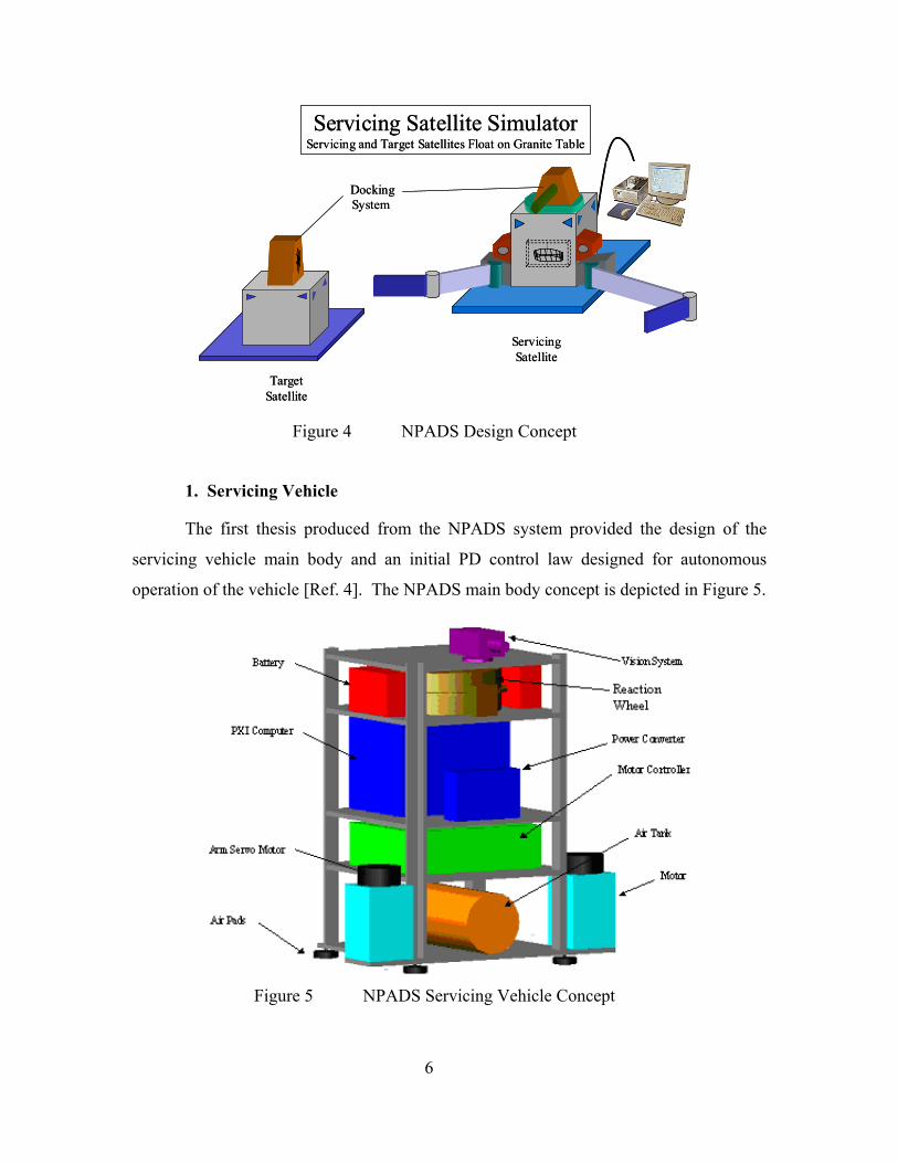
the capture and manipulation devices (robotic arms). Figure 4 provides an illustration of
the NPADS design concept; as shown in the figure, the NPADS system will eventually
expand to include a target vehicle as well.
5
Servicing Satellite SimulatorServicing and Target Satellites Float on Granite Table
TargetSatellite
DockingSystem
ServicingSatellite
Servicing Satellite SimulatorServicing and Target Satellites Float on Granite Table
TargetSatellite
DockingSystem
ServicingSatellite
Figure 4 NPADS Design Concept
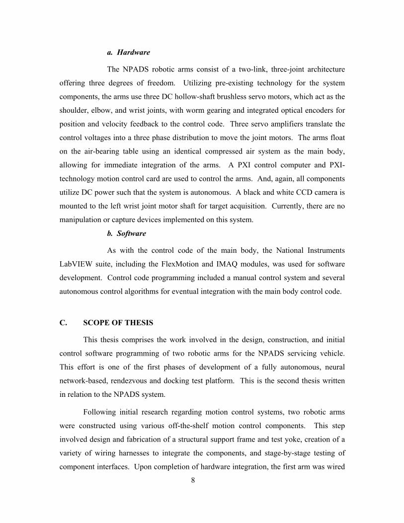
1. Servicing Vehicle
The first thesis produced from the NPADS system provided the design of the
servicing vehicle main body and an initial PD control law designed for autonomous
operation of the vehicle [Ref. 4]. The NPADS main body concept is depicted in Figure 5.
Figure 5 NPADS Servicing Vehicle Concept
6
□

a. Hardware
The NPADS servicing vehicle utilizes a compressed air system to provide
floatation of the vehicle on an air-bearing granite table, thus providing two dimensional
freedom of motion, simulating a 2D space environment. The vehicle includes an onboard
PXI computer for control, which makes use of a reaction wheel and eight gas thrusters to
regulate position and orientation. A black and white CCD camera, acting as a star sensor,
and a MEMS angular rate sensor provide feedback to the attitude determination and
control program. To provide freedom of motion and total autonomy, all of the systems
operate on DC power provided by two lead-acid batteries and a series of voltage
converters. A wireless Ethernet connection allows the control computer to offload data
for processing by an off-board workstation. The vehicle also includes a forward-looking
CCD camera for target detection, though this device has not yet been implemented.
b. Software
The NPADS main body has both manual control and autonomous control
programs. These algorithms were developed using the National Instruments LabVIEW
software suite.
2. Robotic Arms
This thesis provides the characteristics for the two robotic arms designed for
integration onto the servicing vehicle. The initial design concept is illustrated in Figure
6.
CameraCamera
Figure 6 NPADS Robotic Arm Design Concept (After: Ref. 5)
7
a. Hardware
The NPADS robotic arms consist of a two-link, three-joint architecture
offering three degrees of freedom. Utilizing pre-existing technology for the system
components, the arms use three DC hollow-shaft brushless servo motors, which act as the
shoulder, elbow, and wrist joints, with worm gearing and integrated optical encoders for
position and velocity feedback to the control code. Three servo amplifiers translate the
control voltages into a three phase distribution to move the joint motors. The arms float
on the air-bearing table using an identical compressed air system as the main body,
allowing for immediate integration of the arms. A PXI control computer and PXI-
technology motion control card are used to control the arms. And, again, all components
utilize DC power such that the system is autonomous. A black and white CCD camera is
mounted to the left wrist joint motor shaft for target acquisition. Currently, there are no
manipulation or capture devices implemented on this system.
b. Software
As with the control code of the main body, the National Instruments
LabVIEW suite, including the FlexMotion and IMAQ modules, was used for software
development. Control code programming included a manual control system and several
autonomous control algorithms for eventual integration with the main body control code.
C. SCOPE OF THESIS
This thesis comprises the work involved in the design, construction, and initial
control software programming of two robotic arms for the NPADS servicing vehicle.
This effort is one of the first phases of development of a fully autonomous, neural
network-based, rendezvous and docking test platform. This is the second thesis written
in relation to the NPADS system.
Following initial research regarding motion control systems, two robotic arms
were constructed using various off-the-shelf motion control components. This step
involved design and fabrication of a structural support frame and test yoke, creation of a
variety of wiring harnesses to integrate the components, and stage-by-stage testing of
component interfaces. Upon completion of hardware integration, the first arm was wired
8
to the control computer in order to accomplish electronic tuning of the joint motors and
initial testing of the system using pre-programmed software. Once system integrity was
established, a manual control code was built and tested; then, several autonomous control
subroutines designed for integration into the NPADS control architecture were
developed. Finally, a vision system was integrated to provide target acquisition. This
research concluded with successful testing of each of the control algorithms and
integration of the first arm onto the NPADS servicing vehicle. The second arm was
connected to the test harness for future development and research.
9

THIS PAGE INTENTIONALLY LEFT BLANK
10
II. HARDWARE & INTEGRATION
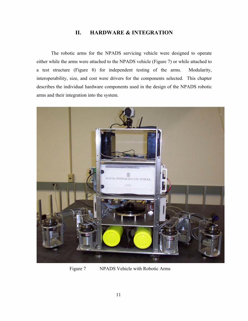
The robotic arms for the NPADS servicing vehicle were designed to operate
either while the arms were attached to the NPADS vehicle (Figure 7) or while attached to
a test structure (Figure 8) for independent testing of the arms. Modularity,
interoperability, size, and cost were drivers for the components selected. This chapter
describes the individual hardware components used in the design of the NPADS robotic
arms and their integration into the system.
Figure 7 NPADS Vehicle with Robotic Arms
11
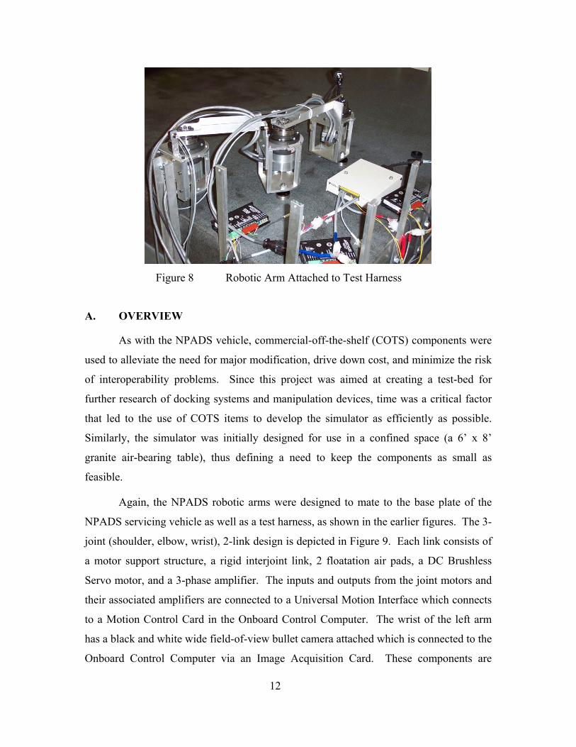
Figure 8 Robotic Arm Attached to Test Harness
A. OVERVIEW
As with the NPADS vehicle, commercial-off-the-shelf (COTS) components were
used to alleviate the need for major modification, drive down cost, and minimize the risk
of interoperability problems. Since this project was aimed at creating a test-bed for
further research of docking systems and manipulation devices, time was a critical factor
that led to the use of COTS items to develop the simulator as efficiently as possible.
Similarly, the simulator was initially designed for use in a confined space (a 6’ x 8’
granite air-bearing table), thus defining a need to keep the components as small as
feasible.
Again, the NPADS robotic arms were designed to mate to the base plate of the
NPADS servicing vehicle as well as a test harness, as shown in the earlier figures. The 3-
joint (shoulder, elbow, wrist), 2-link design is depicted in Figure 9. Each link consists of
a motor support structure, a rigid interjoint link, 2 floatation air pads, a DC Brushless
Servo motor, and a 3-phase amplifier. The inputs and outputs from the joint motors and
their associated amplifiers are connected to a Universal Motion Interface which connects
to a Motion Control Card in the Onboard Control Computer. The wrist of the left arm
has a black and white wide field-of-view bullet camera attached which is connected to the
Onboard Control Computer via an Image Acquisition Card. These components are
12
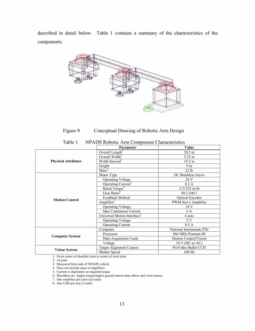
described in detail below. Table 1 contains a summary of the characteristics of the
components.
Figure 9 Conceptual Drawing of Robotic Arm Design
Table 1 NPADS Robotic Arm Component Characteristics
Parameter Value Overall Length1 20.5 in Overall Width2 5.25 in Width Stowed3 15.5 in Height 9 in
Physical Attributes
Mass4 22 lb Motor Type DC Brushless Servo Operating Voltage 24 V Operating Current5 0.2 A Rated Torque6 115/233 in-lb Gear Ratio6 50:1/100:1 Feedback Method Optical Encoder Amplifier7 PWM Servo Amplifier Operating Voltage 24 V Max Continuous Current 6 A Universal Motion Interface8 4 axis Operating Voltage 5 V
Motion Control
Operating Current 0.5 A Computer National Instruments PXI Processor 866 MHz Pentium III Data Acquisition Cards Motion Control/Vision Computer System
Voltage 24 V (DC or AC) Target Alignment Camera ProVideo Bullet CCD Vision System Shutter Speed 100 Hz
1. From center of shoulder joint to center of wrist joint 2. At joint 3. Measured from side of NPADS vehicle 4. Does not include mass of amplifiers 5. Current is dependent on required torque 6. Shoulders are higher torque/higher geared motors than elbow and wrist motors 7. One amplifier per joint (six total) 8. One UMI per arm (2 total)
13

B. STRUCTURES
The joint motor support structure was constructed using 6061-T6 Aluminum and
was designed to minimize weight and height, while providing the structural integrity
necessary for the expected torques placed on the joints. Each support structure is
comprised of a 1/4-inch base plate which supports 2 air pads (elbow and wrist only), a
1/4-inch split top plate with tensioning screws to mate around the joint motor housing, a
1/4-inch back plate (elbow and wrist only) that allows for connection to the link, and four
1/2-inch square rods acting as standoffs. Since the shoulder joint drives the height of the
arm, the elbow and wrist standoffs were designed such that their air pads would be even
with the granite table when the floatation system was off. The frame uses 10-32 screws
to connect the individual pieces.
The arm links are again constructed of 6061-T6 Aluminum. The links are 2-inch
by 1-inch by 1/8-inch channel, 9-inches long. In one end, holes are drilled for mounting
to the joint motor shaft, in the other, mounting holes allow connection to the back plate of
the next joint motor support with a groove cut such that the joint motor wiring harnesses
can reside within the channel. The link to back plate connection is made using 10-32
screws, the link to motor connection is accomplished using M6 screws. Figure 10
illustrates the joint motor support structure and joint linkages. Appendix A contains
detailed drawings of these structural components.
Figure 10 Structural Components
14
Shoulder Housing Elbow/Wrist
Housing
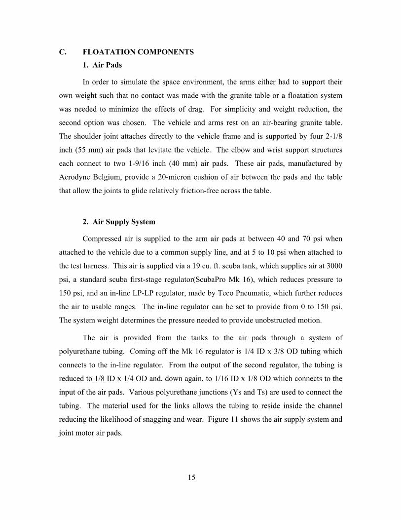
C. FLOATATION COMPONENTS
1. Air Pads
In order to simulate the space environment, the arms either had to support their
own weight such that no contact was made with the granite table or a floatation system
was needed to minimize the effects of drag. For simplicity and weight reduction, the
second option was chosen. The vehicle and arms rest on an air-bearing granite table.
The shoulder joint attaches directly to the vehicle frame and is supported by four 2-1/8
inch (55 mm) air pads that levitate the vehicle. The elbow and wrist support structures
each connect to two 1-9/16 inch (40 mm) air pads. These air pads, manufactured by
Aerodyne Belgium, provide a 20-micron cushion of air between the pads and the table
that allow the joints to glide relatively friction-free across the table.
2. Air Supply System
Compressed air is supplied to the arm air pads at between 40 and 70 psi when
attached to the vehicle due to a common supply line, and at 5 to 10 psi when attached to
the test harness. This air is supplied via a 19 cu. ft. scuba tank, which supplies air at 3000
psi, a standard scuba first-stage regulator(ScubaPro Mk 16), which reduces pressure to
150 psi, and an in-line LP-LP regulator, made by Teco Pneumatic, which further reduces
the air to usable ranges. The in-line regulator can be set to provide from 0 to 150 psi.
The system weight determines the pressure needed to provide unobstructed motion.
The air is provided from the tanks to the air pads through a system of
polyurethane tubing. Coming off the Mk 16 regulator is 1/4 ID x 3/8 OD tubing which
connects to the in-line regulator. From the output of the second regulator, the tubing is
reduced to 1/8 ID x 1/4 OD and, down again, to 1/16 ID x 1/8 OD which connects to the
input of the air pads. Various polyurethane junctions (Ys and Ts) are used to connect the
tubing. The material used for the links allows the tubing to reside inside the channel
reducing the likelihood of snagging and wear. Figure 11 shows the air supply system and
joint motor air pads.
15

Figure 11 Floatation Components
D. POWER COMPONENTS
The overriding goal of this research was simulating autonomy. In keeping with
this goal, all system components run on DC power, such that batteries could be used to
provide the power necessary to run the entire vehicle and the arms. A system of two
Panasonic 12-Volt, 20-Amp hour lead-acid batteries are wired in series on the vehicle to
provide a 24-Volt output. The battery layout is provided in Figure 12.
Figure 12 NPADS Batteries
A system of DC-DC converters is used on the vehicle to provide ±5V, +6V,
+12V, and +18V required for various components of the NPADS vehicle. The joint
motors, amplifiers, and control computer run directly off the batteries at 24V. However, 16
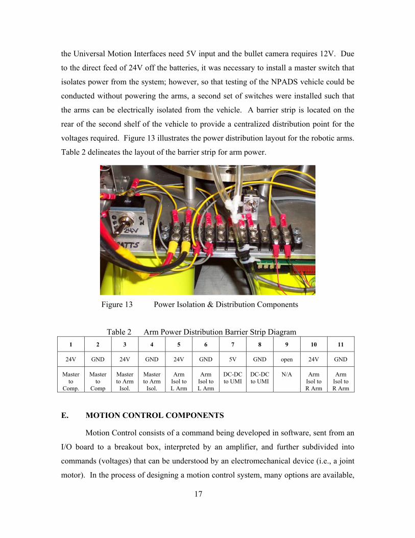
the Universal Motion Interfaces need 5V input and the bullet camera requires 12V. Due
to the direct feed of 24V off the batteries, it was necessary to install a master switch that
isolates power from the system; however, so that testing of the NPADS vehicle could be
conducted without powering the arms, a second set of switches were installed such that
the arms can be electrically isolated from the vehicle. A barrier strip is located on the
rear of the second shelf of the vehicle to provide a centralized distribution point for the
voltages required. Figure 13 illustrates the power distribution layout for the robotic arms.
Table 2 delineates the layout of the barrier strip for arm power.
Figure 13 Power Isolation & Distribution Components
Table 2 Arm Power Distribution Barrier Strip Diagram 1 2 3 4 5 6 7 8 9 10 11
24V GND 24V GND 24V GND 5V GND open 24V GND
Master to
Comp.
Master to
Comp
Master to Arm
Isol.
Master to Arm
Isol.
Arm Isol to L Arm
Arm Isol to L Arm
DC-DC to UMI
DC-DC to UMI
N/A Arm Isol to R Arm
Arm Isol to R Arm
E. MOTION CONTROL COMPONENTS
Motion Control consists of a command being developed in software, sent from an
I/O board to a breakout box, interpreted by an amplifier, and further subdivided into
commands (voltages) that can be understood by an electromechanical device (i.e., a joint
motor). In the process of designing a motion control system, many options are available,
17
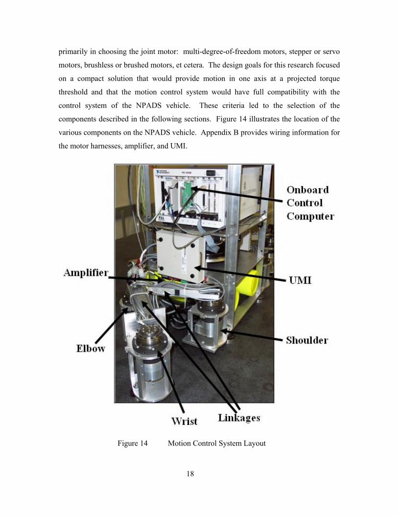
primarily in choosing the joint motor: multi-degree-of-freedom motors, stepper or servo
motors, brushless or brushed motors, et cetera. The design goals for this research focused
on a compact solution that would provide motion in one axis at a projected torque
threshold and that the motion control system would have full compatibility with the
control system of the NPADS vehicle. These criteria led to the selection of the
components described in the following sections. Figure 14 illustrates the location of the
various components on the NPADS vehicle. Appendix B provides wiring information for
the motor harnesses, amplifier, and UMI.
Figure 14 Motion Control System Layout
18
Ainplifiei
Elbow
Oiibo;iid Coiiti'ol Compufer
UMI
Shoulder
Wiist Link^^g*^^
1. Joint Motors
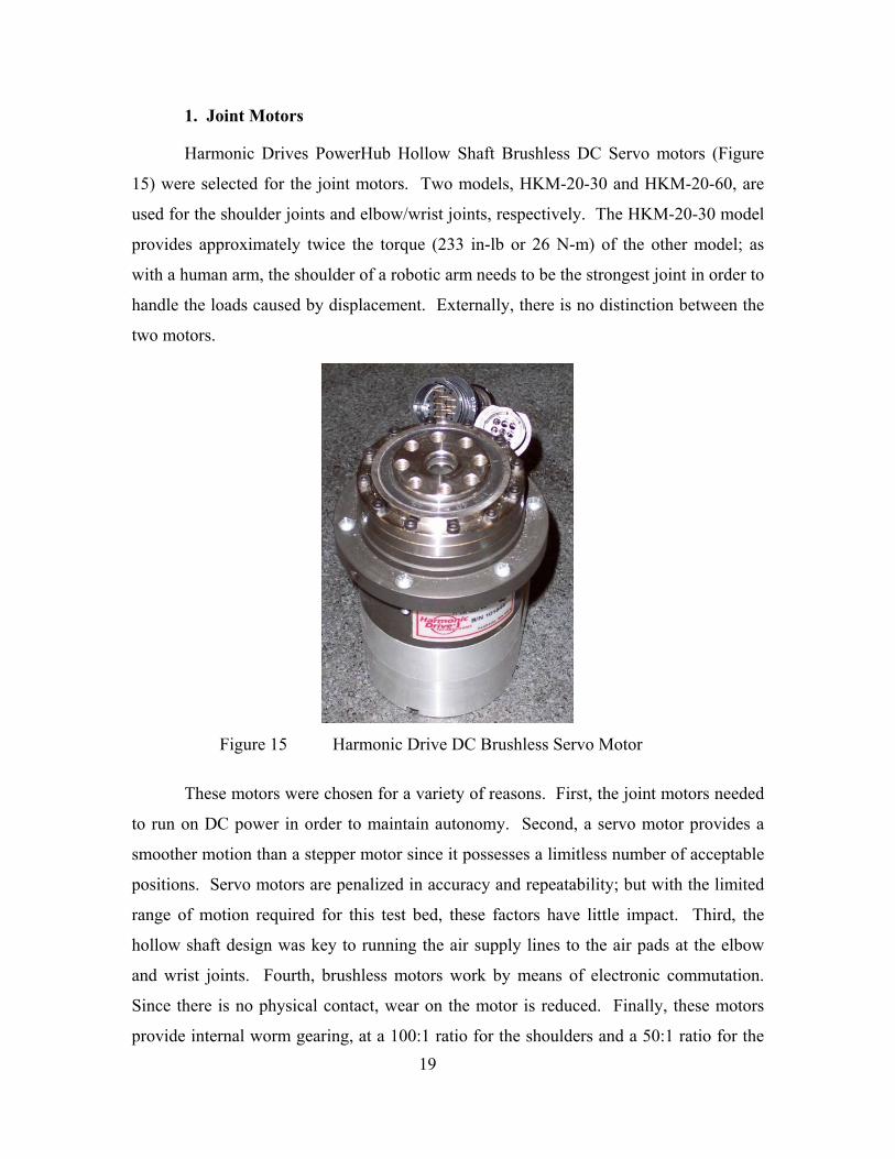
Harmonic Drives PowerHub Hollow Shaft Brushless DC Servo motors (Figure
15) were selected for the joint motors. Two models, HKM-20-30 and HKM-20-60, are
used for the shoulder joints and elbow/wrist joints, respectively. The HKM-20-30 model
provides approximately twice the torque (233 in-lb or 26 N-m) of the other model; as
with a human arm, the shoulder of a robotic arm needs to be the strongest joint in order to
handle the loads caused by displacement. Externally, there is no distinction between the
two motors.
Figure 15 Harmonic Drive DC Brushless Servo Motor
These motors were chosen for a variety of reasons. First, the joint motors needed
to run on DC power in order to maintain autonomy. Second, a servo motor provides a
smoother motion than a stepper motor since it possesses a limitless number of acceptable
positions. Servo motors are penalized in accuracy and repeatability; but with the limited
range of motion required for this test bed, these factors have little impact. Third, the
hollow shaft design was key to running the air supply lines to the air pads at the elbow
and wrist joints. Fourth, brushless motors work by means of electronic commutation.
Since there is no physical contact, wear on the motor is reduced. Finally, these motors
provide internal worm gearing, at a 100:1 ratio for the shoulders and a 50:1 ratio for the 19
elbows and wrists, and an integrated optical encoder (4000 counts/rev of drive shaft).
The addition of these two subcomponents greatly simplified the prospect of component
integration and interoperability.
2. Amplifiers
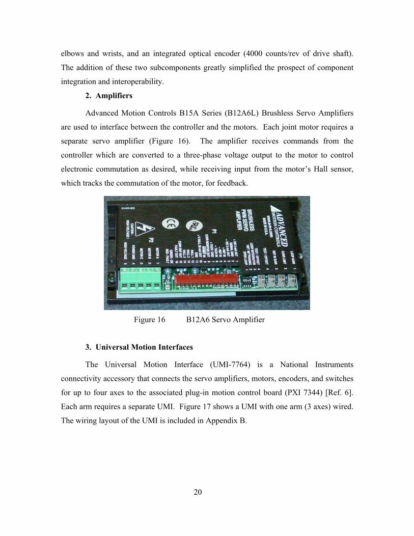
Advanced Motion Controls B15A Series (B12A6L) Brushless Servo Amplifiers
are used to interface between the controller and the motors. Each joint motor requires a
separate servo amplifier (Figure 16). The amplifier receives commands from the
controller which are converted to a three-phase voltage output to the motor to control
electronic commutation as desired, while receiving input from the motor’s Hall sensor,
which tracks the commutation of the motor, for feedback.
Figure 16 B12A6 Servo Amplifier
3. Universal Motion Interfaces
The Universal Motion Interface (UMI-7764) is a National Instruments
connectivity accessory that connects the servo amplifiers, motors, encoders, and switches
for up to four axes to the associated plug-in motion control board (PXI 7344) [Ref. 6].
Each arm requires a separate UMI. Figure 17 shows a UMI with one arm (3 axes) wired.
The wiring layout of the UMI is included in Appendix B.
20

Figure 17 Universal Motion Interface
4. Home Switches
As mentioned previously, the optical encoder is located on the drive shaft of the
joint motors. Consequently, there are multiple Index signals per single revolution of the
output shaft, therefore it is impossible to identify a repeatable reference location at
power-up using the encoders. To alleviate this problem, a series of Normally Off-
Momentary On switches were placed at the parked (power-up) position of the shoulder
and elbow joints so that software could be developed to find home, the repeatable
reference position, each time the system were initialized. This function will be further
defined in a later section. Figure 18 shows one of these switches.
Figure 18 Home Switch
21

F. COMPUTER AND ASSOCIATED COMPONENTS
1. Chassis and Controller
On the second level of the NPADS vehicle, an onboard computer is mounted
which controls all vehicle operations including motion control of the robotic arms. The
computer, made by National Instruments, includes a chassis (1000B), controller (PXI
(PCI eXtensions for Instrumentation) 8175), and various input/output cards described
below. The 1000B chassis allows for both AC and DC operation and includes a
controller interface and seven expansion slots for additional cards. The PXI 8175
controller is driven by an 866 MHz Pentium III processor, includes a hard drive, 3-1/2
inch floppy drive, Ethernet port, USB ports, and the standard interfaces of a desktop
computer, and operates under the Windows 2000 operating system. PXI technology
allows for a much more compact system by pushing many of the specialized functions to
the expansion cards for processing. Figure 19 shows the onboard computer.
Figure 19 NPADS Onboard Computer
2. PXI 7344 Motion Controller Card
The PXI 7344 Motion Controller uses a dual-processor architecture with high
speed communications to allow on-card processing of up to four axes (motors), either
22
8175 Controller 1408 IMAQ Card 7344 Motion Control Card
stepper or servo, executing up to ten simultaneous motion programs, with 62
microsecond PID/PIF servo updates, encoder feedback up to 20 MHz, and various limit
and trigger inputs [Ref. 7]. Each Motion Controller drives one robotic arm since there
are three joint motors (axes) per arm. The 7344 board connects to a UMI via a 68-pin
VHDCI connector.
3. PXI 1408 Image Acquisition (IMAQ) Card
The PXI 1408 is a monochrome IMAQ board that supports up to four video inputs
from most standard video sources, using 8-bit flash analog to digital conversion to
acquire and store an image [Ref 8]. The left robotic arm includes a black and white
camera, mounted on the wrist, which provides video input to the PXI 1408 card. The
1408 board connects to the camera via a BNC connector.
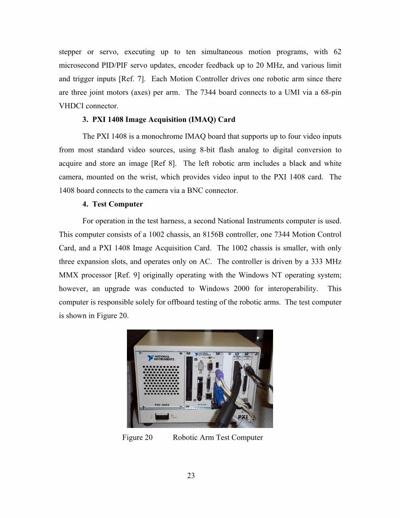
4. Test Computer
For operation in the test harness, a second National Instruments computer is used.
This computer consists of a 1002 chassis, an 8156B controller, one 7344 Motion Control
Card, and a PXI 1408 Image Acquisition Card. The 1002 chassis is smaller, with only
three expansion slots, and operates only on AC. The controller is driven by a 333 MHz
MMX processor [Ref. 9] originally operating with the Windows NT operating system;
however, an upgrade was conducted to Windows 2000 for interoperability. This
computer is responsible solely for offboard testing of the robotic arms. The test computer
is shown in Figure 20.
Figure 20 Robotic Arm Test Computer
23

G. VISION COMPONENTS
A ProVideo CVC-320WP CCD camera is attached to the wrist of the left robotic
arm and is used for target acquisition/position verification. The camera contains a 1/3
inch fixed focal length image sensor that operates at a shutter speed of 100 Hz. The
bullet camera is powered by 12 VDC. Figure 21 shows the camera mounted on the left
wrist.
Figure 21 Robotic Arm Bullet Camera
24
III. CONTROL SOFTWARE
Development of software for the NPADS robotic arm motion control system was
accomplished using the National Instruments LabVIEW 6i software suite and associated
modules. By leveraging a single vendor for both hardware and software for much of the
motion control system, interoperability and translation problems were bypassed.
National Instruments PXI technology is based on:
… an architecture that supports mechanical, electrical, and software features tailored to industrial instrumentation, data acquisition, and automation applications [Ref 9, 1-3].
Through backplane interfacing with the various specialty control boards, the PXI
controller is able to schedule tasks more efficiently. LabVIEW was developed by
National Instruments to take advantage of this architecture.
LabVIEW is a graphical programming language; unlike traditional languages
such as FORTRAN or C, LabVIEW uses a series of icons, which are visual
representations of commands or subroutines, and a wiring tool to connect icons to one
another to create a functional program. For many of the specialty control boards,
modules are included in the LabVIEW suite for function-specific commands; for
example, the 7344 Motion Control card uses many commands included in the
FlexMotion module – these commands are tailored for motion control applications. The
chapter that follows discusses the development of the LabVIEW control program and
subroutines designed for operation of the NPADS robotic arms.
A. OVERVIEW
The motion control program was developed in several stages. Initially, once
hardware integration was completed, it was necessary to calculate the gains for each joint
motor to ensure stable operation. Normally an intensive set of calculations using
experimental data and basic control equations is required; however, LabVIEW includes a
tool called the Measurement & Automation Explorer (MAX) which contains a set of sub-
programs, as part of the FlexMotion software module, designed to test servo motors and 25

identify gains and other useful parameters. Thus, the relatively difficult task of tuning the
joint motors was simplified greatly through the automated method included in the
software suite. Next, to verify operational stability and test the ability to control the
motors, a Manual Control program was developed using standard LabVIEW commands
in conjunction with those in the FlexMotion module. Finally, a series of autonomous
subroutines were developed for eventual use in the NPADS robotic arm onboard control
program. Though manual control was tested briefly on the NPADS vehicle to verify
telerobotic control, all tests and operations using the autonomous code to date have been
conducted on the test harness.
B. MOTOR TUNING
Measurement & Automation Explorer is a versatile tool used to ensure proper,
efficient interaction between computer hardware, software, and third party functional
hardware. Figure 22 shows the MAX Configuration menu for the test computer. Under
the Devices and Interfaces folder are subfolders for the computer ports and the two
expansion cards: IMAQ PXI-1408 and PXI-7344. Also, under the 7344 subfolder, the
various functional folders for Motion Controller setup and initialization can be seen. In
short, the Device Resources folder provides motion controller to chassis interface
information, Default 7344 Settings (see Appendix C) enables the user to input specifics
of third party motors and feedback devices such that signals can be passed between the
controller and these components (an example is presented in Figure 23), the Interactive
folder provides the option of 1-D or 2-D manual control of joints for testing connectivity,
and Calibration includes the tools for automatically or manually tuning servo motors.
26

Figure 22 Measurement & Automation Explorer Configuration Menu
Figure 23 MAX Default 7344 Setting Axis Configuration Menu
27
'My Syilemj
tt f*"' FJei^hbnhuod ^1 Devices and Inl:«faces
El [^ Ir*(}P5I-140S ; tnfi m jy Porti(Setal&P3wW) Blii p«-7344(n
^ Device Resources B IS Def s« 7344 ielhngs
E Jig AXIS Configuration a lli Axs Settings B ll^ Tiaiectary Settngs B (l0 tUru&Ir>deiSettr B li^ Di^l/03ettT>9S B i^ GeamgSettng^
B li^ ADC Setln95 l±l ijg EiKoder SHUigs
B 1^ PWM Setlngs El S InterKlivs
lai l-D Interactive S 2-OIntsKtive
B (^ CatbreCion if^ Servo Tune
* ^ IVI Instruments • IB Scales .-- 6] SoPtware
B S5 ^i^"5f* Sysfems
!£ MAX - AKII Canli9urstiiin
Eile E« Ifow logls tJufc
I ^InUBla flj Change Setuigs i^lvxtl
.jAjxl
9 Hy S/tlw .•. li Cma Hcrftxrhaoil K ^B Device; aid Inteffaces
•I d ]nAQP):r-l4DS:ii>gO «l j'PmtiC^nul&PwalEO i| ilPXr-7344(l)
is Mvlce RsSDucet a<$M«*n44M^^
B9 AiKSMttig! &- Jd Tiertdoiv Ssttings E^' id Hcmeabitei SAUigs a IB DiBUI[/0 Settings SigGestig Settings Sili'U'C Sittings E id Encodef Settrqs E .Sj PWMSettngs
^gi Tntsadive eii i'DTntnanrve B0 ^-D bddf active
E Q CMntbart ■pl SflfvoTune
E k 1V1 Imtiinml! EBScslet (^ d ScAvae ^ Remote Systems
I J-iJ
[^Rehesh ^DefeiAt
rr. JAxIs Configuration
^ |A>K Corhguabci
Dav^riplion Confiauei Ihe dm depenifr>g on Uv F:^ of moUir and leottack d&viu
(^ SBIVO
^ Enditod
Conbol Low Uodtf e Ponod
PiinaiijOL'pur
Sacondary Feedback.
SBCoodary Output
138micrcKeccindE jH
3
11 Encodei t SteppHBenUion
Encode! coum per revofcjbon
r SteppH S riecie S etirgt -
-$t«fipHUC(>U«» 1 rSlwwEoMj 1 (* GDP-ILODP *• fic'rveirivi
r UD->edLiJoD C AcweHrgli
Stqipa Elepi pa [avofciBfin
"=J - StoppB QiKpU Mnle
C Stept&ireclwn
r Oo*me/lj»n<or Clockwiie
E2_A« Corti9u*on

The only option under the Calibration folder is Servo Tune, which contains five
pages for various control settings and testing. The first of these pages is Main, which
allows the user to choose which axis to tune and the method (manual or automatic). The
Manual option was used for tuning the NPADS robotic arms. The middle three pages
provide tools for generating a Step Response, Trajectory, and Bode plot for a given set of
parameters. The final page, Control Loop, allows the user to vary the value of the PID
control gains for the motion control system on the given axis. Changing the values of the
proportional gain (Kp), derivative gain (Kd), integral gain (Ki), and derivative sampling
period (Td) provide various, often unstable, results during the iterative process of servo
tuning. Following the instructions provided by National Instruments’ online support
center [Ref 10] for manually tuning a motor, all six joint motors were tested and
categorized. Figure 24 shows the interactive Control Loop page used to manually adjust
the PID control parameters. Appendix C provides the calculated gains.
Figure 24 MAX Servo Tune Control Loop Page
Following motor tuning, the aforementioned 1-D interactive module of MAX
allowed preliminary testing of the joints individually to ensure proper performance. This
28
f^ Servo Tine
S' r0D Gate Propotond Gtm DetivalTve Gevi Inte^aJ Gw
Kp
ICOOO-r
8000-
eooo-
«no-
2000-
0-^
fK
10D0O--
8000-
GOOO-
KOa-
200Q-
0-?
10000-p
eooo-
EOOO-
4000-
a>oo-
0-^
'±11™ iJF "d
-KelodlyFeedHckGw-
Kv
10000- ■
flOOO-
GOOO-
4000-
ajoo-
0-^
"d ^onfrte^GavQ- - Feedfoiwdid Ga^is-
[2 iJ [Tooo 2J [0 lJ[o IJ
rlcuqusOHieli- PiinavDAC SscondoyDAC Selit^ Ihe Stw Respcuas lab lo iM ttw slep
. I respoiBe and ttie Traiedoty Mb to (W ttie
Q Main | ^ Step Reawrse [ d Tuiectay | c| Bode jj Conlid Laip F
testing proved 360 degree motion, velocity control, positional control, encoder operation
and verified encoder count for the output shaft as 400,000 counts per revolution for the
shoulder motors and 200,000 counts per revolution for the elbow/wrist motors (the
difference is due to the gear ratio of the two models).
Finally, the most important application of MAX is that once all of the settings are
properly defined and the motors are tuned, MAX saves the data to a configuration file
unique to the controller. Therefore, when control programs, such as the ones that follow,
are written, the configuration file can be called via a FlexMotion icon that will initialize
the 7344 Motion Control card to the parameters saved in that file. Each time the system
is powered down, the controller must be initialized prior to operation of the robotic arms.
C. COMBINED CONTROL
1. Combined Control Code Interface
The MAX 1-D interactive module provided an important tool in testing
operability of the joints individually, but a 3-D control program was needed to fully flex
the controller to ensure that multi-joint operations were feasible. The design philosophy
behind the manual control program focused on creating a real-time command-in, desired
outcome-out system with relatively user-friendly control implementation. LabVIEW, as
stated previously, is a graphical programming language. A LabVIEW program consists
of two parts: a diagram, which is a graphical illustration of the program flow, and a front
panel, which forms the I/O (input-output) interface between the user and the program.
Built into the language is the ability to readily create controls (such as knobs and slide
bars) and indicators (such as dials and digital readouts) on the front panel, corresponding
to functions on the diagram, to facilitate use of a program. Capitalizing on these built-in
functions and for simplicity of testing and demonstration, both the manual control
program and the subsequent autonomous control programs are built into one diagram and
front panel. Figure 25 shows the appearance of the full control program front panel. The
Emergency Stop switch (top left) and the Joint Velocity and Position indicators (top
right) are shared by all sub-programs.
29

Figure 25 NPADS Robotic Arm Manual/Autonomous Controls Front Panel
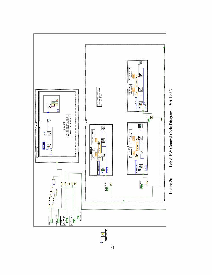
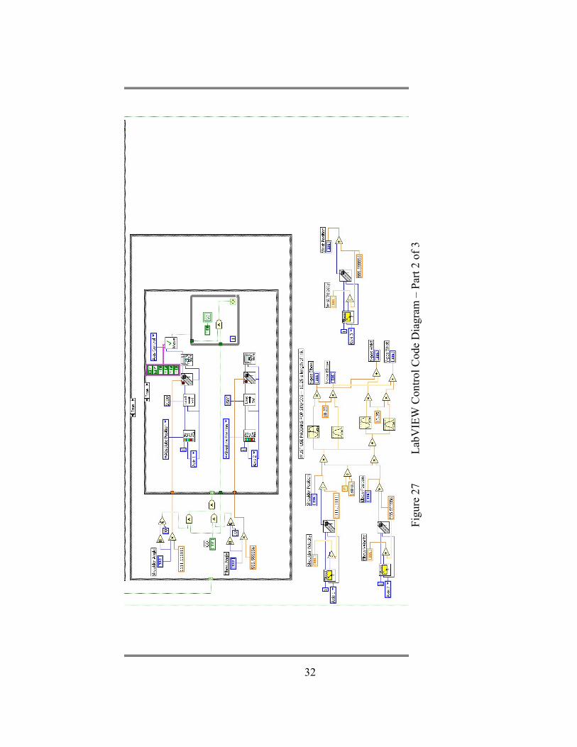
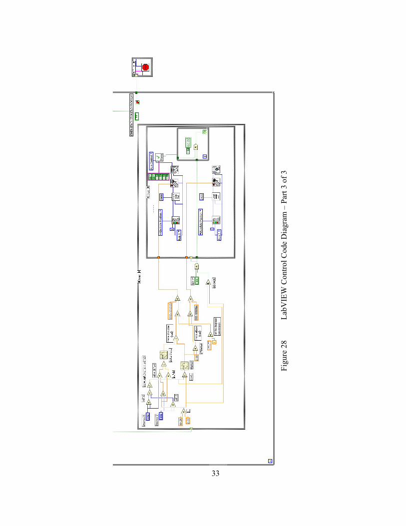
2. Combined Control Code
As stated in the previous section, both the manual and autonomous control codes
are part of a single program. Figure 26, Figure 27, and Figure 28, on the following pages,
show the LabVIEW diagram in its entirety. The rectangular structures in the diagram
represent loops or subroutines of various types. The outer rectangle is a while loop that
allows the code to continue operation as long as the Emergency Stop routine is not
activated. The inner loops of the Control Code diagram, from top to bottom, are the
Home Finder subroutine, Manual Control subroutine, Commanded Angle subroutine,
Commanded X-Y subroutine, and Visual Target Acquisition subroutine. These
subroutines are discussed in detail later in this chapter.
30
|3W Pos.X
Cora Area
1309
1» !■
31
Figu
re 2
6 La
bVIE
W C
ontro
l Cod
e D
iagr
am –
Par
t 1 o
f 3
r
32
Figu
re 2
7 La
bVIE
W C
ontro
l Cod
e D
iagr
am –
Par
t 2 o
f 3
33
Figu
re 2
8 La
bVIE
W C
ontro
l Cod
e D
iagr
am –
Par
t 3 o
f 3
B

The Emergency Stop routine, displayed in Figure 29, checks for an input from the
Emergency Stop button on the front panel (represented by the T F box wired from the
left, in the diagram) and uses the Case structure (rectangular frame) to determine the
necessary operations. If the signal is false (no input), the main While loop continues
running and the Stop routine continues monitoring the signal for input; if true (input), the
main While loop discontinues and all motors on the appropriate control card are sent a
Kill command to disable power flow, stopping the motors. This feature was implemented
for safety during testing. When the program is stopped, the motors are sent a Kill
command as well.
Figure 29 Emergency Stop Routine Code
Another item of note is the Initialize Controller routine on the left side of the
diagram, outside the while loop. This routine (Figure 30) is a FlexMotion Virtual
Instrument (VI), a subroutine or command provided with the software suite, that reads the
current motion control configuration file developed using Measurement & Automation
Explorer, as mentioned in the section on Motor Tuning. The constant (number) wired to
the icon identifies which 7344 Motion Controller is to be loaded with the configuration
file. This routine commences upon program initiation.
Figure 30 Initialize Controller Routine Code
34
I EMERGENCY STOP/END PPQGPflMi
|ml
&
jlnitialize Controllef I

After controller initialization, the main While loop is entered and the code waits
for a functional selection by the user. The front panel master switches discussed earlier
control this selection. To ensure that the motion control system receives commands from
a single subroutine at a given time, the Boolean mechanism illustrated in Figure 31 uses a
series of comparisons (Boolean gates) to verify that only one function is chosen. The
dashed lines represent the command lines connected to the various subroutine loop
structures.
Figure 31 Switching Mechanism Code
Finally, Figure 32 shows the code providing output to the indicators on the front
panel. For each joint, calculations are completed based on encoder feedback signals and
the motor parameters (i.e., counts per revolution) to provide instantaneous motor
velocity, motor position relative to the reference-zero, and (x,y) position for the elbow
and wrist joints. This figure illustrates the ease of integration between FlexMotion VIs
(i.e., “FILTERED” gauge, which reads encoder signals for velocity, and the road icon,
which reads position) and standard LabVIEW VIs (i.e., trigonometric functions and
mathematical expressions). This algorithm runs independent of any of the other
subroutines – outputs are provided continuously following controller initialization.
35
hOf^FM)^
MAMUAL COMTROLI
UiJHUHleir) go<aije<go
I X^Y rUrfcouideJ)
um—- ^<panaQn 5lQt|

36
Figu
re 3
2 Po
sitio
n an
d V
eloc
ity In
dica
tor C
ode
> •/I —
•/I s _ si
D. MANUAL CONTROL
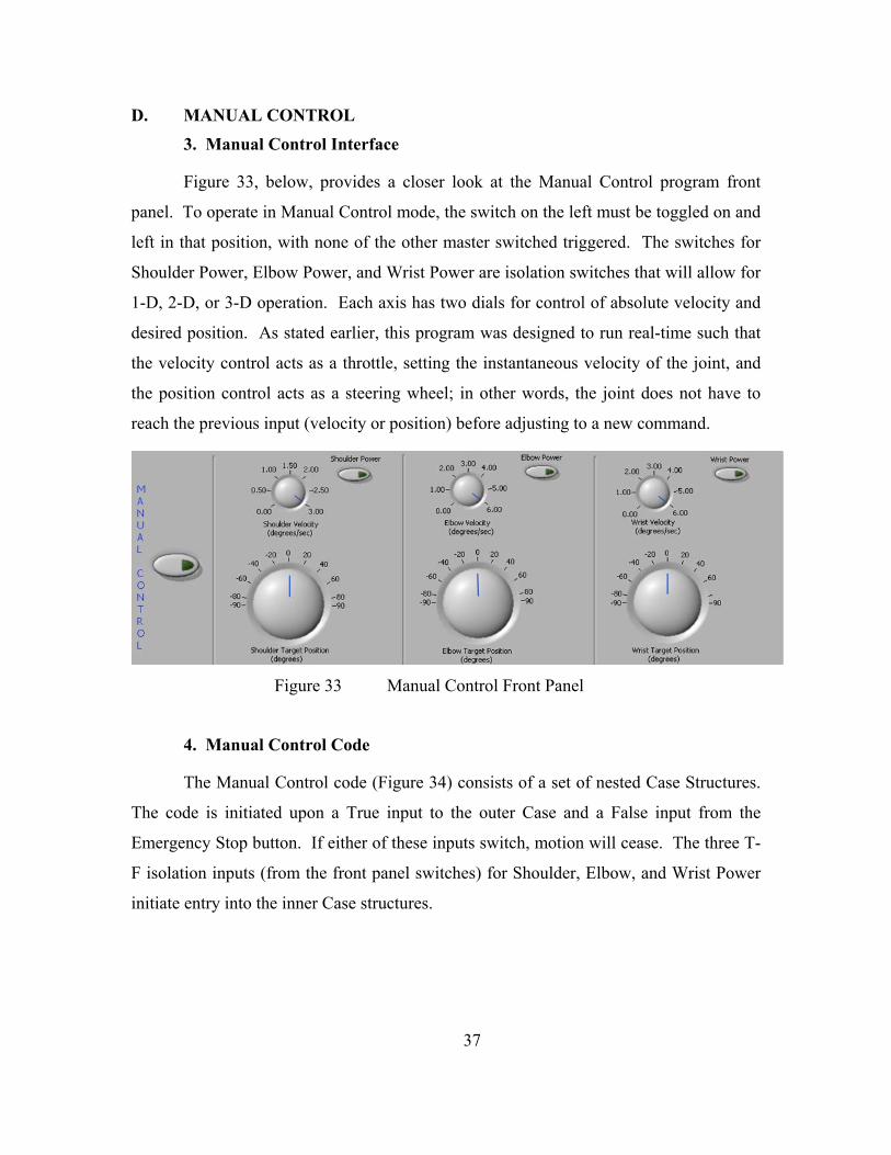
3. Manual Control Interface
Figure 33, below, provides a closer look at the Manual Control program front
panel. To operate in Manual Control mode, the switch on the left must be toggled on and
left in that position, with none of the other master switched triggered. The switches for
Shoulder Power, Elbow Power, and Wrist Power are isolation switches that will allow for
1-D, 2-D, or 3-D operation. Each axis has two dials for control of absolute velocity and
desired position. As stated earlier, this program was designed to run real-time such that
the velocity control acts as a throttle, setting the instantaneous velocity of the joint, and
the position control acts as a steering wheel; in other words, the joint does not have to
reach the previous input (velocity or position) before adjusting to a new command.
Figure 33 Manual Control Front Panel
4. Manual Control Code
The Manual Control code (Figure 34) consists of a set of nested Case Structures.
The code is initiated upon a True input to the outer Case and a False input from the
Emergency Stop button. If either of these inputs switch, motion will cease. The three T-
F isolation inputs (from the front panel switches) for Shoulder, Elbow, and Wrist Power
initiate entry into the inner Case structures.
37

2^ u C en > o £ n
zi 1^ :^
■^ Q c
0
^
38
Figu
re 3
4 M
anua
l Con
trol C
ode
!^
iS^
'A
Q
i^

Figure 35 Joint Operation/Isolation Code
Figure 35 provides the two paths within the inner Cases. If the joint power switch
is ON, the True case (left) is initiated and the user will experience real-time control of the
joint using the front panel controls for velocity and position. These controls are
restrained to +/- 90 degrees in position (all joints) and 3 degrees per second (shoulders) or
6 degrees per second (elbows and wrists) in velocity for better control and safety. The
code uses FlexMotion’s Absolute Position mode with variable inputs to the Load Position
and Load Velocity VIs to create instantaneous control. Since a Case structure is used, as
long as the switches remain True, the functions inside the structure will continue to run.
If the joint power switch is OFF, the False case (right) is initiated and the joint is
given a Halt command (the motor still receives power from the amplifier to hold position)
using the Stop Motion VI. As long as the Manual Control master switch remains ON and
the Emergency Stop signal remains False, the isolation switches can be turned ON and
OFF at will to provide simultaneous control of the desired number of joints.
E. AUTONOMOUS CONTROL
A single autonomous control algorithm was not created in the course of this
thesis. Rather, a set of four autonomous subroutines were designed to provide for
autonomous functionality of the robotic arms when integrated with the NPADS vehicle
control program. These subroutines provide tools aimed at autonomy and various
approaches to interaction with a vehicle based targeting architecture. The design
philosophy focused on generating a set of algorithms that could be commanded by
39
TiLekr™" Shoulder Target Position
(degrees)

various inputs, thus facilitating flexibility in control system integration at such time that
the arms are mated permanently with the vehicle.
The autonomous subroutines are meant for implementation into a governing
control program, namely that of the NPADS vehicle. Each subroutine provides a
segment of the autonomous control loop: self-knowledge, targeting, and control. Figure
36 provides a basic schematic of the robotic arm control scheme and identifies the
subroutine associated with each function [Ref. 11]. The figure shows that tuning the
motors provides the PID gain inputs to the control system and the subroutines described
in the following sections supply the three components listed above, creating a standard
closed-loop control system.
Figure 36 Autonomous Control System Block Diagram
1. Home Finder
a. Home Finder Interface
The first step in the process of autonomy involved devising a method to
provide an accurate, repeatable reference point at power up, such that the joint has
knowledge of its position at all times. As stated in the previous chapter, the joint motors
are equipped with an optical encoder that includes an Index mark. LabVIEW’s
FlexMotion module includes a Find Index subroutine and, ideally, the Index would be
40
.MAX Servo Tune
SELF-KNOWLEDGE (Reference Zero)
\
Home Finder
GAINS (Kp.Ki.Kd)
TARGETING (Camera)
Vision
PLANT (Amps, Motors)
FEEDBACK (Encoders)
T Commanded Angle/X-Y

used as the reference point; however, since the encoder is situated on the drive shaft,
prior to the gearing, the Index is found multiple times per revolution of the output shaft,
the number of times being determined by the gear ratio. For an application where the
motors were turning many revolutions, the Index would be a useful tool; but, joint motion
of the arms is restricted to less than one revolution, which makes the Index signal useless
since a dependable, repeatable instance is unlikely.
To alleviate this problem, using FlexMotion tools, a new subroutine was
created to be run only at power-up to find and set a reference position. To ensure
repeatability, the momentary switches mentioned in Chapter II were situated on the
shoulder and elbow joints such that when the arms are in a stowed configuration, the
inter-joint linkages would make contact with the switches. This subroutine causes the
joint motors, one at a time, to move toward their respective home switch until contact is
made. Once the computer receives the signal that Home is found, the position can be set
to a MAX-defined value, whether zero or some other location. This feature and more
details of the code are provided in the next section. Figure 37 shows the Home Finder
trigger on the front panel, alongside the three joint position and velocity indicators
(velocity is provided in degrees per second and position in degrees).
Figure 37 Home Finder Trigger with Velocity and Position Indicators
b. Home Finder Code
As with the Manual Control Code described above, and all of the
following autonomous subroutines, the Home Finder code is built inside a Case structure
to enable use of the Boolean switch. Within the Case Structure lies a Sequence structure,
having the appearance of a film frame, which allows a sequence of operations to be
carried out one at a time. There are seven frames to this sequence: two for each joint and
one frame to end the subroutine. Figure 38 shows the two frames required to find the
reference position for the right shoulder joint. The frame on the left utilizes FlexMotion 41
HOME FINDER
C3 Shoulder Velocity Wrist Velocity
|0.0
Shoulder Position
^0 ——
Velocity control, with a constant input to the Load Velocity VI causing the shoulder joint
motor to continue moving clockwise (positive direction) until the momentary switch
triggers that Home is found. The While loop on the right side of the left frame causes a
continuous query of the Home Input, checking for contact. Once contact is verified, the
motor is stopped and the Sequence moves to the next frame (Figure 38, right) where the
Reset Position VI renames the current position to the position desired. Table 3 lists the
stowed positions for the shoulder and elbow joints of the two arms. Though the
algorithm included code for the wrist, the wrist joints have been ignored until such time
as there is a manipulator or grapple mechanism installed so that the switches can be
placed appropriately.
42
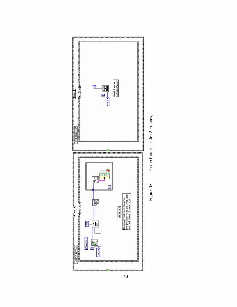
43
Figu
re 3
8 H
ome
Find
er C
ode
(2 F
ram
es)

Table 3 Desired Home Positions LEFT ARM
Shoulder -172,500 counts Elbow +65,750 counts
RIGHT ARM Shoulder +175,500 counts
Elbow -65,750 counts
The final frame of the sequence, displayed in Figure 39, provides a means
to end the Home Finder function. The Master Switch is created as a Local Variable and
when the subroutine has completed the sequence and gets to this frame, the master switch
is tripped to the OFF position. For implementation in the NPADS control code, this
frame can be used to change a reference bit such that the algorithm is recognized as
complete.
Figure 39 Home Finder Code (Final Frame)
2. Commanded Angle
a. Commanded Angle Interface
Once the initial position of the joints are known, a method for
commanding the arm must be defined. The first approach designed fed directly from the
Manual Control program: angular commands. The front panel, shown in Figure 40, is a
system of a master switch, two commanded angle digital controls, and a send command
switch. Once the master switch is triggered, the user utilizes the two digital controls to
provide desired absolute angular positions for the shoulder and elbow joints; then,
depressing the GO button sends the command to the controller. The desired angles must
44
I HOME FUNCTION I '^iTm. ^r*
BBaaaaaaaaaaaa iuijj),| 6ro,,6i^.pBBaaaaaaaaaaaaaaai
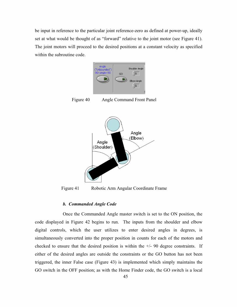
be input in reference to the particular joint reference-zero as defined at power-up, ideally
set at what would be thought of as “forward” relative to the joint motor (see Figure 41).
The joint motors will proceed to the desired positions at a constant velocity as specified
within the subroutine code.
Figure 40 Angle Command Front Panel
Figure 41 Robotic Arm Angular Coordinate Frame
b. Commanded Angle Code
Once the Commanded Angle master switch is set to the ON position, the
code displayed in Figure 42 begins to run. The inputs from the shoulder and elbow
digital controls, which the user utilizes to enter desired angles in degrees, is
simultaneously converted into the proper position in counts for each of the motors and
checked to ensure that the desired position is within the +/- 90 degree constraints. If
either of the desired angles are outside the constraints or the GO button has not been
triggered, the inner False case (Figure 43) is implemented which simply maintains the
GO switch in the OFF position; as with the Home Finder code, the GO switch is a local 45
(i-rtjounted') ■90 tangle < 90

variable. Once the desired angles are verified and the GO button is triggered ON, the
inner Case structure is entered for the True case. Motion is initiated using FlexMotion
Absolute Position mode with a constant velocity input to the Load Velocity VIs and the
Load Position VIs being fed by the converted positions mentioned earlier. The Move
Complete VI checks both axes to verify that the commanded angles have been reached
for both the elbow and shoulder. Once motion is complete, the While loop on the right is
entered and switches the GO switch to the OFF position, ending operation of the case.
46

47
Figu
re 4
2 C
omm
ande
d A
ngle
Cod
e (T
rue
Inne
r Cas
e)

Figure 43 Commanded Angle Code (False Inner Case)
3. Commanded X-Y
a. Commanded X-Y Interface
The second approach is derived from the initial control algorithm used by
the NPADS vehicle to identify its position on the granite table: x-y commands [see Ref.
4]. Figure 44 illustrates the X-Y Command front panel, which includes the same basic
user controls as the previous subroutine as well as x and y position indicators for the
centers of the elbow and wrist joints (in inches). Figure 45 describes the robotic arm
coordinate system used for this algorithm. The (0,0) point is set as the center of the
shoulder joint hollow shaft. Again, the user sets the Desired X and Desired Y digital
controls for desired wrist joint position, then presses the GO XY button to initiate motion.
As above, the arm joints are driven at a constant velocity set in the program code to the
user-defined wrist position. Due to the length of the arm, wrist position is limited to
positions within a semi-circle having a radius of 20.5 inches (0.52 m).
Figure 44 X-Y Command Front Panel
48
X-Y (■Unbounded-)
r
00 XY
De*edx ■ X-posEbow
.'o Y-pos Ebow
In
C^ CJ^ Dsst^Y P X-posWrbt
|o Y-pos Wrist
1° ^
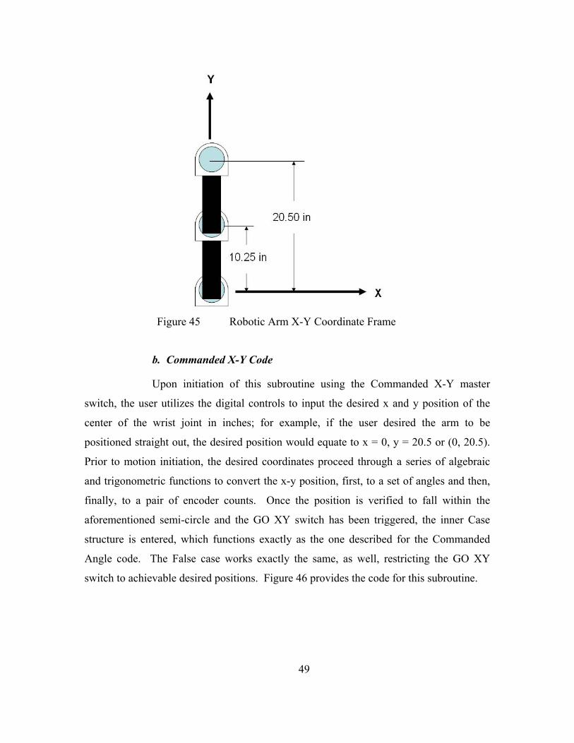
Figure 45 Robotic Arm X-Y Coordinate Frame
b. Commanded X-Y Code
Upon initiation of this subroutine using the Commanded X-Y master
switch, the user utilizes the digital controls to input the desired x and y position of the
center of the wrist joint in inches; for example, if the user desired the arm to be
positioned straight out, the desired position would equate to x = 0, y = 20.5 or (0, 20.5).
Prior to motion initiation, the desired coordinates proceed through a series of algebraic
and trigonometric functions to convert the x-y position, first, to a set of angles and then,
finally, to a pair of encoder counts. Once the position is verified to fall within the
aforementioned semi-circle and the GO XY switch has been triggered, the inner Case
structure is entered, which functions exactly as the one described for the Commanded
Angle code. The False case works exactly the same, as well, restricting the GO XY
switch to achievable desired positions. Figure 46 provides the code for this subroutine.
49
*• X

50
Figu
re 4
6 C
omm
ande
d X
-Y C
ode
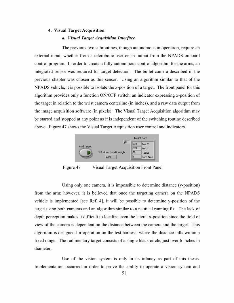
4. Visual Target Acquisition
a. Visual Target Acquisition Interface
The previous two subroutines, though autonomous in operation, require an
external input, whether from a telerobotic user or an output from the NPADS onboard
control program. In order to create a fully autonomous control algorithm for the arms, an
integrated sensor was required for target detection. The bullet camera described in the
previous chapter was chosen as this sensor. Using an algorithm similar to that of the
NPADS vehicle, it is possible to isolate the x-position of a target. The front panel for this
algorithm provides only a function ON/OFF switch, an indicator expressing x-position of
the target in relation to the wrist camera centerline (in inches), and a raw data output from
the image acquisition software (in pixels). The Visual Target Acquisition algorithm may
be started and stopped at any point as it is independent of the switching routine described
above. Figure 47 shows the Visual Target Acquisition user control and indicators.
Figure 47 Visual Target Acquisition Front Panel
Using only one camera, it is impossible to determine distance (y-position)
from the arm; however, it is believed that once the targeting camera on the NPADS
vehicle is implemented [see Ref. 4], it will be possible to determine y-position of the
target using both cameras and an algorithm similar to a nautical running fix. The lack of
depth perception makes it difficult to localize even the lateral x-position since the field of
view of the camera is dependent on the distance between the camera and the target. This
algorithm is designed for operation on the test harness, where the distance falls within a
fixed range. The rudimentary target consists of a single black circle, just over 6 inches in
diameter.
Use of the vision system is only in its infancy as part of this thesis.
Implementation occurred in order to prove the ability to operate a vision system and 51

motion control system concurrently and to provide support for future growth. The only
degradation experienced operating the systems simultaneously occurred with the front
panel indicators. When the vision system is running, the position and velocity indicator
update rate is slowed significantly.
b. Visual Target Acquisition Code
LabVIEW’s Image Acquisition (IMAQ) Module and Image Builder were
used to construct the algorithm shown in Figure 48. Unlike the previous subroutines, this
code was developed to run concurrent with any of the other functions; therefore the
Boolean Find Target switch is not wired through the switching mechanism discussed
earlier. Once the master switch is turned ON, the Case structure is entered and image
acquisition begins and continues until the switch is triggered OFF. A snapshot, or single
image, is captured from the bullet camera mounted on the wrist of the left arm. Using
IMAQ tools, the snapshot is filtered of clutter and edge noise. The new image is then
further filtered to identify circular structures that fall in a set range of diameters. The
range is specific to the distance expected while the arm is mounted to the test harness.
Once the circle has been identified, the VI outputs raw Target Data in pixels, which is
sent to the front panel. The Target Data includes circle center x (horizontal) and y
(vertical) position in pixels from the upper left corner of the image, the radius of the
circle in pixels, and the core area which comes from a set algorithm in the VI. The raw
x-position is then converted into the x-position from the center of the camera (center of
the wrist joint) in inches. The image is 680 pixels wide, so the raw position is subtracted
from the halfway point and then converted to inches using a pixels per inch conversion
factor. This conversion factor is determined by the proximity of the target, but is set in
the code for test harness operation. The code will continue to output target position as
long as the target is visible to the camera and the master switch is ON.
52

1^
S
i
El-
53
Figu
re 4
8 V
isua
l Tar
get A
cqui
sitio
n C
ode
ra

THIS PAGE INTENTIONALLY LEFT BLANK
54
IV. OPERATION AND PERFORMANCE
Nearly all testing and operation of the robotic arms was conducted using the test
harness, in order to minimize risk to the NPADS vehicle and to provide independent
testing of the arms during the concurrent development of the vehicle main body. This
chapter describes the procedures utilized during this thesis for operation of the robotic
arms and provides performance data for the subroutines described in the previous
chapter. Though the majority of arm operations occurred on the test stand, a brief
explanation of the operational procedures for an arm joined to the NPADS vehicle is
provided as well.
A. ROBOTIC ARM OPERATION
As with testing of all powered equipment, there are procedures for start-up,
operation, and shutdown of the robotic arm and its associated equipment. The following
sections describe the initial setup of the robotic arm, on the test stand and the main body,
as well as these procedures.
1. Robotic Arm Test Setup
The robotic arm components used during operation on the test harness are exactly
the same as those used when the arm attaches to the NPADS vehicle, with the exception
of a smaller, AC-powered PXI computer (described in Chapter II). Figure 49 illustrates
the location of the major components at the fixed base location. Not shown in the figure
is the floatation air supply system, comprised of a thirteen cubic foot compressed air tank
and two pressure regulators supplying 5-10 psi air to the air pads, located beneath the
granite table directly below the test harness. To conserve battery life and to eliminate the
need of a second set of DC-DC converters, three AC-powered DC power supplies are
used to supply 5, 12, and 24 Volts to the various system components.
As mentioned previously, the zero position of the arm is with the two links
aligned directly forward of the test harness as shown in Figure 50. This figure displays
55

also the connection of the shoulder motor housing to the test harness and the visual target
located across the table from the arm.
Figure 49 Robotic Arm Test Setup
Figure 50 Test Harness Arrangement, Zero Reference Configuration
56
Servo Amplifiers Test Harness Slioulder Elbow UMI Wrist Camera
^'^'' Motor/Amplifier Power Supply p^^^^ gupply
{5V) (24V)
Camera Power Supply
(12V)
Test Computer

2. Robotic Arm Pre-Operation
In order to ensure safe, proper operation of the robotic arm while attached to the
test harness, a sequence of tasks need to be performed prior to system operation.
Adherence to these procedures ensures the safety of personnel and equipment as well as
providing a systematic check of the robotic arm components. Table 4 lists the Pre-
Operation procedures.
Table 4 Robotic Arm Pre-Operation Checklist Action Notes
1. Clean Granite Table Use fine brush and Silicon spray
2. Check general condition of wiring and hoses
3. Verify floatation tank full and pressure set correctly Should provide 5-10 psi. Test by briefly turning on air.
4. Turn on Test Computer No password required
5. Initialize PXI 7344 Motion Control Card Open MAX>Devices and Interfaces>PXI-7344>Device Resources, press Initialize in Upper Left corner
6. Turn on UMI Power 5V Power Supply, verify connection
7. Turn on Motor/Amplifier Power 24V Power Supply, verify connections
8. Verify Amplifier LEDs light GREEN Located next to MOLEX connector
9. Turn on Camera Power (only if using Vision system) 12 V Power Supply, verify connections
10. Turn on floatation air
11. Test for positive control of all three joints Use MAX>Devices and Interfaces>PXI-7344 >Interactive>1D Interactive. Use Velocity control at low speed (1000-2000 counts/s), press Apply and then Start choosing one joint at a time to verify control and feedback. Use KILL to stop motion.
12. Align arm to Zero Reference Configuration Use 1D interactive to maneuver joints such that they align as in Figure 50. As each joint is positioned correctly, press Reset Position and the joint position will be set to zero.
WARNING: If the feedback system is not initialized properly or feedback signals are lost for some reason, the joint WILL move, but at a faster velocity than anticipated. Be ready to initiate KILL to stop motion. If initialization is incorrect, reset the motion control card (see Post-Operation procedures), disconnect power to all components, reboot the test computer, and begin the Pre-Operation procedures again.
3. Robotic Arm Operation
Once the Pre-Operation checklist is completed, the robotic arm is ready for
operation using the Combined Control program described in the last Chapter. On the test
57

harness, commands are sent from the test computer through the Motion Control Card to
the UMI for redistribution to the motion control components.
If the arm is integrated with the main body, there are two modes of operation
available. If the computer peripherals (i.e., mouse, keyboard, and monitor) are connected
to the NPADS control computer, the Combined Control program data flow will act just as
it would on the test harness. If the NPADS vehicle is wireless, however, the robotic arm
control program must follow Data Socket initialization procedures [Ref. 4] such that an
offboard DAQ computer can act as a command terminal to upload commands via the
wireless Ethernet. Wireless operation of the Manual Control code was verified briefly
through testing, but only to prove the capability.
4. Robotic Arm Post-Operation
In order to conserve consumables and ensure that the system is ready for follow-
on operations, a series of Post-Operation procedures are required to shut down the
system. Table 5 lists the steps required following robotic arm operation.
Table 5 Robotic Arm Post-Operation Checklist Action Notes
1. Align arm at safe position Using either Manual Control or MAX 1D Interactive, move the arm to a position on the table appropriate for stowage.
2. Exit Control Program If not already done
3. KILL all axes Use MAX 1D Interactive to KILL the Shoulder, Elbow, and Wrist joints
4. Turn off floatation air Refill tank, if necessary
5. Turn off Camera Power (if used)
6. Turn off Motor/Amplifier Power Open MAX>Devices and Interfaces>PXI-7344>Device Resources, press Initialize in Upper Left corner
7. Turn off UMI Power 5V Power Supply, verify connection
8. Reset 7344 Motion Control Card Use MAX>Devices and Interfaces>PXI-7344 (Status Page), press Reset Device, ensure that controller shows Power Up Reset.
9. Shut Down Test Computer Use Windows START menu to Shut Down the computer and turn off power when prompted.
10. Check general condition of wiring and hoses
WARNING: If the system is not shut down in order, inadvertent motion at system start-up may result.
58

5. Robotic Arm NPADS Integration Setup
For integration onto the NPADS main body, the robotic arm shoulder joint is
mounted to the wing of the vehicle base plate. Figure 51 provides the location of the
major components of the motion control system.
Figure 51 Robotic Arm NPADS Main Body Integration Setup
Though the majority of the Pre- and Post-Operation procedures are the same as
when the arm is connected to the test harness, there are several additional electrical
features on the body mounted system to ensure user and equipment welfare. These
isolation switches, mentioned in Chapter II, are shown in Figure 52 and the procedures
for their use are listed in Table 6. The only switch not shown is the NPADS vehicle DC
conversion plate switch which provides the 5V supply to the UMI Power Switch. This
switch is located on the underside of the second shelf, on the left side (looking forward),
directly above the reaction wheel [see Ref. 4]. The camera will be wired into the vehicle
59
NPADS Control Computer UMI Shoulder Elbow Wrist
Arm Power Servo Amplifiers Wiring Home Distribution Harnesses Switches
power distribution center; therefore, power will be supplied when the DC conversion
switch is turned on.
Figure 52 Robotic Arm Procedural Components on NPADS Vehicle
Table 6 Robotic Arm On-Vehicle Checklist Addendum Pre-Operation
Action Notes
6a. Verify batteries are fully charged and connected Two batteries in series should be above 21V
6b. Turn on DC conversion switch
6c. Turn on UMI Power Switch
7a. Turn on 24V Master Switch
7b. Turn on Arm Power Isolation Switch(es)
Post-Operation
Action Notes
6a. Turn off Arm Power Isolation Switch(es)
6b. Turn off 24V Master Switch
7a. Turn off UMI Power Switch
7b. Turn off DC conversion switch
7c. Charge batteries, if necessary Two batteries in series should be above 21V
WARNING: If the system is not isolated properly, inadvertent damage or injury could result.
60
24V Master Switch UMI Power Switch Right Arm Power Isolation Switch
Floatation Air Supply Valve

B. ROBOTIC ARM PERFORMANCE
The control algorithms developed for the robotic arms, described in the previous
Chapter, were each tested to ensure that acceptable performance standards were met. The
grading criteria included precision of joint movement versus commanded input and
system response speed. The following sections will illustrate the results of these tests, in
which all of the subroutines proved highly reliable. This performance analysis also
served to verify the PID system gains derived from the tuning of the motor through the
Measurement & Automation Explorer.
1. Manual Control Performance
The first software to be tested was the Manual Control code. Utilizing the test
harness, the arm was initialized to zero angle settings for all three joints, as described
above, using the 1D Interactive feature of MAX. The Combined Control code was
started and the Manual Control code master switch was placed in the ON position. All
three joints were powered up using the isolation switches and a series of simultaneous
movements and velocity changes were used as the profile. Table 7 provides the series of
commands provided to the robotic arm. Figure 53, Figure 54, and Figure 55, below,
provide the Desired (commanded) and Actual (output) positions and velocities for the
shoulder, elbow, and wrist joints, respectively. In all three cases, the joint motors
responded well to the command inputs, showing no degradation even with all three joints
online. Of note, the Actual Velocity matches the Desired only during a positional change
and Desired Velocity is entered as an absolute and translated by the controller based on
relative location to the Desired Angle.
The single disparity in this test shows up on the right side of the Angular Velocity
plot for the Elbow (Figure 54, bottom right). There are two spikes in the Desired
Velocity even though Elbow movement is stopped. This discrepancy comes from one of
the Wrist joint air pads being improperly aligned and introducing a minute frictional
force during Shoulder movement which caused the Elbow to initiate motion to hold
position. Alignment of the air pads alleviated the divergence, but the inadvertent
discrepancy proves that the system will adjust to maintain a commanded value.
61
Table 7 Manual Control Code Test Profile Joint Command Notes
-20 degrees, 3 degrees/s Initial set velocity at power up
1.25 degrees/s
-37 degrees Shoulder
-2 degrees, 2.5 degrees/s Velocity change after move starts.
5 degrees/s Initial set velocity at power up
4 degrees/s
15 degrees
9 degrees/s, changed to 4 degrees/s
-50 degrees, 9 degrees per second Velocity change after move starts
Elbow
0 degrees, 3.5 degrees/s
3.75 degrees/s Initial set velocity at power up
2.5 degrees/s
-22 degrees Wrist
-0.5 degrees, 3 degrees/s Velocity change after move starts
Figure 53 Manual Control Profile for Shoulder Joint
62
Manual Control Position Profile (Shoulder)
I -500
?-10KI
T-1500
I'M 00
■D-KilO
■3-30KI
°-3500
-lorti 500 000
S -500 w
Ji-1000
f-1500 f-2000
2.!500 3-3000
"-3500 -4000
-20 40 EO 00 I 100 1JQ
§ -^ w ^0 30 IMJ^ I:O
S i Ilnn|9
Manual Control Velocity Profile (Shoulder)
35
S. 25
f 15 o " 1
ncd
5^
= -3 <
js m m so iBD 110
I, ; 2L _!B HL
Iin«H
Move Initiated
Mid-move Velocity Change
Figure 54 Manual Control Profile for Elbow Joint
Figure 55 Manual Control Profile for Wrist Joint
63
Manual Control Position Profile (Elbow)
Manual Control Velocity Profile (Elbow)
Time (4
Move Initiated
Manual Control Position Profile (Wrist)
5.00
0 00
-5 00
-10.00
-15.00
-20.00
■ 20 40 260 80 100 KO
•
1 1
1 1
Time |s|
Manual Control Velocity Profile (Wrist)
Move Initiated Mid-move Velocity Change

2. Home Finder Performance
The single function tested on the NPADS main body was the Home Finder
algorithm. MAX was used to initialize the robotic arm in a false zero reference frame to
prove that the zero position would be reset during the algorithm. Testing occurred on the
vehicle to verify that the stowed position of the arms would not negatively impact any of
the arm or vehicle assemblies.
As described in Chapter III, the right Shoulder joint was moved in the positive
direction until contact was made with the Home Switch, Shoulder position was reset to
the correct zero reference position, and then the procedure was repeated for the Elbow.
Figure 56 shows the position of the Home Switch (i.e., On or Off) and the movement of
the two joints. As illustrated, the Shoulder is reset to 158 degrees (175,500 counts) and
the Elbow to -118 degrees (-65,750 counts). Figure 57 provides the velocities of the two
joints through the algorithm; as stated in Chapter III, motion occurs at fixed velocities.
Figure 56 Home Finder Profile for Shoulder and Elbow Position
64
Home Finder Profile
start Algorithm/ Start Shoulder Motion
(Position)
C A 1
O T
* .. E -
6 0.2
.n V >^ 10 20 30 « so «C
-20. IB S-
20.00
. 0.00 1 ,K——'^''
J 10 M 30 40 ^*U. Gl ""---.^
Elbow Home Found/ Reset Position
Tlim(4

Figure 57 Home Finder Profile for Shoulder and Elbow Velocity
3. Commanded Angle Performance
Commanded Angle testing utilized the test harness. MAX was again used to set
the proper zero reference condition and then the arm was moved slightly off zero. The
Combined Control code was started and the Commanded Angle master switch was placed
in the ON position. A series of angular commands were given to the arm using the digital
controls and the GO switch. Table 8 supplies the series of commands provided to the
robotic arm. Figure 58 provides the Desired Angle and the joint position and velocity
response for both the Shoulder and Elbow. Both joints responded accurately.
Though not easily recognizable in the plots, the Desired Angle for the Shoulder
joint actually leads motion initiation. This is due to algorithm information flow. The
user enters the desired angles, obviously one at a time, then initiates motion with the GO
switch. During testing, the Shoulder angle was always entered first and therefore the
Desired Angle changes immediately, but the arm does not respond until the switch is
toggled. And again, the velocity of each joint is held constant within the algorithm.
65
Home Finder Profile (Velocity)
-- 1 o ^ ■
I
o 0
f^ 10 20 30 "O 33 DP
-0 5D
1 CO -
^ 05D -
S oco.
>! -1 CO -
D -1 5D -
> -2(B -
"5 -2 5D -
1 1 ^^^^^^^^H
V
^ 10 20 30 do :o op
start
Table 8 Commanded Angle Control Code Test Profile Command Shoulder Angle
(degrees) Elbow Angle
(degrees)
1 0 0
2 -30 25
3 15 -35
4 0 0
Figure 58 Commanded Angle Profile for Shoulder and Elbow
4. Commanded X-Y Performance
Commanded X-Y testing also utilized the test harness. And again, the zero
reference position was initiated using MAX and the arm was moved slightly off zero.
The Combined Control code was started and the Commanded X-Y master switch was
placed in the ON position. Various planar positioning commands were given to the arm
using the digital controls and the GO XY switch. Table 9 provides the series of positions
supplied to the robotic arm. Figure 59 illustrates the path of the wrist joint as it is driven
66
Commanded Angle Profile (Shoulder)
£ IS
■s.-'B
■c -2)
^■3]
1 ^H
20 « EO 80
Tlmel^
Commanded Angle Profile (Elbow)
X
~ ZJ % S. 10
1-10
SL -2]
3)
^ 1
2] 0] ED ED
1
Tlrra(s)

to the Desired position. Figure 60 shows the joint position and velocity response for both
the Shoulder and Elbow required to place the wrist in the Desired position.
Due to the set deadband (+/- 10 counts) of the joint motors, the actual positions
vary slightly from those commanded. The deadband is a region on the encoder, defined
by a motion controller default setting using MAX, within which a commanded movement
is considered complete. The positional error due to this setting is within one tenth of an
inch, therefore the arm joint responses are deemed adequate and accurate.
Command 6 (see Table 9) was included to test system response to an illegal
command, one beyond the reach of the arm. As shown, even though the command was
given, the arm remained motionless as anticipated. The Desired X position suffers from
the lead time issue discussed in the previous section, since all positions were entered X,
then Y prior to GO XY initiation. Once again, the absolute velocity of each joint is held
constant within the algorithm.
Table 9 Commanded X-Y Control Code Test Profile Command Wrist X Position
(inches) Wrist Y Position
(inches)
1 0 20.5
2 -20 4
3 -2 15
4 -10 12
5 2 18
6 21 18
7 0 20.5
67

Figure 59 Commanded X-Y Profile for Wrist Position
Figure 60 Commanded X-Y Profile for Shoulder and Elbow
68
Commanded XY Profile (X Position)
Commanded XY Profile (Y Position]
250
Time (s| Illegal Command (Beyond Constraint)
Time (s|
Commanded XY Profile (Shoulder Position & Velocity)
Commanded XY Profile [Elbow Position & Velocity)
Time(^ Timels)
5. Visual Target Acquisition Performance
The vision-based Target Acquisition algorithm was tested primarily to establish a
reliable conversion factor, as discussed in Chapter III, which allowed for an accurate
distance measurement of a circular target from the camera boresight (or center of the
wrist joint) within the range of motion allowable from the fixed base test harness. A
solid black circle, six and a quarter inches in diameter, was used as a primitive target.
Measurements were taken at two extreme positions, straight out (all joints at the zero
position, 46-1/4 inches boresight to target) and fully extended left (Shoulder at -90
degrees, Elbow at 0 degrees, and Wrist at 90 degrees, 66-1/2 inches boresight to target),
using a variety of pixels to inches conversion factors.
The initial settings at each of the two positions were based off the geometric
relationship between distance from camera to target and the pixel width of the frame;
however, due to curvature of the lens, a “fish-eye” effect is experienced and the snapshot
has a residual curvature that produces an error in this approach. Therefore the analysis
provided in Table 10 and Table 11 established the conversion factors necessary at each
position (10.00 straight forward and 7.00 fully extended left). The addition of a range
sensor, or possibly just a second camera, would allow a linear interpolation estimation to
be made for this factor that would provide reasonably accurate X-positions on a
repeatable basis.
69
Table 10 Visual Target Acquisition Code Test Profile (Straight Out) Conversion Factor
(pixels/inches) Target X Distance
(inches) Visual X Distance
(inches)
0 0.00
8 9.88
16 19.02
-8 -9.51
8.20
-24 -26.20
0 0.00
8 9.19
16 18.26
-8 -9.30
8.60
-24 -25.58
0 0.00
8 8.30
16 15.80
-8 -8.10
10.00
-24 -27.50
Table 11 Visual Target Acquisition Code Test Profile (Fully Extended Left) Conversion Factor
(pixels/inches) Target X Distance
(inches) Visual X Distance
(inches)
0 0.00
8 9.97
16 19.42
-8 -9.45
5.82
-24 -27.32
0 0.00
8 5.70
16 11.30
-8 -5.50
10.00
-24 -15.90
0 0.00
8 8.29
16 16.14
-8 -8.00
7.00
-24 -22.71
70

V. SUMMARY AND CONCLUSIONS
A. SUMMARY
The objective of this thesis was to develop a set of robotic arms for the NPS
Planar Autonomous Docking Simulator (NPADS) servicing vehicle by designing a
motion control system, manufacturing a skeletal support structure, integrating the
mechanical and electronic components, and constructing the control software necessary
to operate the system. Off-the-shelf hardware components were used to facilitate
development, since the purpose of the simulator is to provide a test bed for further
research. Following wiring and integration of the various third party components, the
National Instruments LabVIEW suite was used to develop the various algorithms for
control of the robotic arms. Manual control was developed first to test system integrity;
then, a series of autonomous control subroutines were created to provide functionality
within the overall control program of the NPADS vehicle. Incorporation of a wrist
mounted camera enabled the arms to provide a limited, stand alone input for autonomous
operation. This research provided two robotic arms ready for integration onto the
servicing vehicle, integration of grappling mechanisms or manipulators, or testing of
advanced control algorithms.
B. FOLLOW-ON RESEARCH
1. Improvements
The following improvements to the NPADS robotic arms, servicing vehicle, and
test facility are recommended:
• Define the method of command for the robotic arms, and integrate the
autonomous control algorithms into the servicing vehicle control code.
Currently, one arm is mated to the servicing vehicle, the other is mounted on
the test harness to facilitate further testing.
• Modify the control code for the arms to act in a coordinated manner. The
algorithms built for this thesis are capable of being modified to allow this type
71
of operation. Coordinated control would assist the main body control
algorithm by counteracting the torque effects of a single arm in motion as well
as providing the basis for coordinated grapple and capture approaches.
• Develop a vision algorithm for the servicing vehicle targeting camera such
that it can provide target position information as well. Once the wrist camera
and servicing vehicle targeting camera are working in concert, develop an
algorithm to localize position of the target in two dimensions. Implementation
of some form of range finder may be necessary.
• Develop a larger air-bearing surface on which to conduct operation of the
simulator. With the addition of the robotic arms, the granite table will soon
become restrictive. To act as a proper test bed for testing rendezvous and
capture devices, the NPADS system will need a significantly larger area in
which to operate.
• Develop a capture method using the robotic arms to initiate docking with a
target vehicle. Though the NPADS vehicle can act as a test bed for advanced
capture devices, a simple method must be devised in order to test docking
devices alone.
2. Future Work
The addition of robotic arms to the NPADS vehicle greatly increases the
capability of the simulator and moves one step closer to providing an operational test bed.
As stated above, now that the arms are functional, it is critical to integrate the NPADS
system into a single set of control laws. Once the controls are unified, perhaps a more
efficient means of autonomous control can be developed using advanced programming
techniques, such as fuzzy logic or neural networks, so that the simulator can adapt as it
operates. Further, the robotic arms open a plethora of research opportunities at NPS (and
elsewhere) in development of dexterous manipulators, capture devices, docking
mechanisms, and smart targets.
The vision of the simulator was to provide a system that would prove the
necessity of a revolution in satellite design. Building satellites that could have much
72

longer life expectancy due to repair and refueling by a system such as this is an important
consideration from both operational and engineering standpoints. This fact opens up
other areas of continued research, including space operations and architecture, operations
analysis, systems engineering, and risk assessment. The NPADS system provides the
potential for many future research opportunities that will support a variety of Department
of Defense issues and interests among numerous academic disciplines.
73

THIS PAGE INTENTIONALLY LEFT BLANK
74

APPENDIX A: STRUCTURAL DRAWINGS
As mentioned in Chapter II, the joint motor support structures, or joint motor
housings, were constructed using 6061-T6 Aluminum. The Figures that follow provide
the mechanical specifications for the individual pieces that comprise the housings and
linkages. The housings were designed such that the joint motors are securely stationed in
a fixed position to ensure positional repeatability. The open architecture provides heat
dissipation as well as being light-weight.
The top plate, shown in Figure 61, is split and clamped using two 10-32 screws in
order to accommodate the shape of the servo motor and increase stability. The bottom
plate (Figure 62) includes mounting holes for two air pads on the elbow and wrist and a
center hole that takes advantage of the hollow shaft design of the motors by allowing the
air supply line for the air pads to extend through the hollow shaft and this plate. Figure
63 shows the standoffs for the two housing types (shoulder and elbow/wrist). The
shoulder housing has shorter standoffs since there is no need to use the hollow shaft for
air supply. The elbow and wrist housings also include a back plate, shown in Figure 64,
which firmly attaches to the joint motor housing with seven 10-32 screws and the linkage
to the previous joint, with four additional 10-32 screws. Figure 65 shows the arm
linkages, with eight mounting holes, for M6 screws, to the output shaft of the joint motor
and a larger hole central to these eight which allows access to the joint motor hollow
shaft. At the opposite end of the linkage are the four mounting holes which attach at the
back plate and a cutout in the bottom of the channel that enables the joint motor power
and feedback lines to lie inside the channel as well.
75
76Figure 61 Joint Motor Housing Top Plate
n
I' -9- I
fin t ^ Ln
-^-
#:
::- -T- -"""i :::ti: -=I^I:I^^::::i::::|=:ln::II]:::l|:::=^^=lI^^TZ^: -^'---^""^

77Figure 62 Joint Motor Housing Bottom Plate
*l°h
^r^rr\,.\ j.llH
O
in
j.. .
:i ;-;;!;■
:h:l^i!]|^^-^1^|^J^|^jj^:l^tllM■||||■■|. m- ■

78Figure 63 Joint Motor Housing Standoffs (Shoulder, short; Elbow/Wrist, long)
l^
V4
i==:=-a
i;;;;
ii f
pj m
1
■^ -'.
■ILLU ' : : : 1 : ' : 1 —LLLI 11
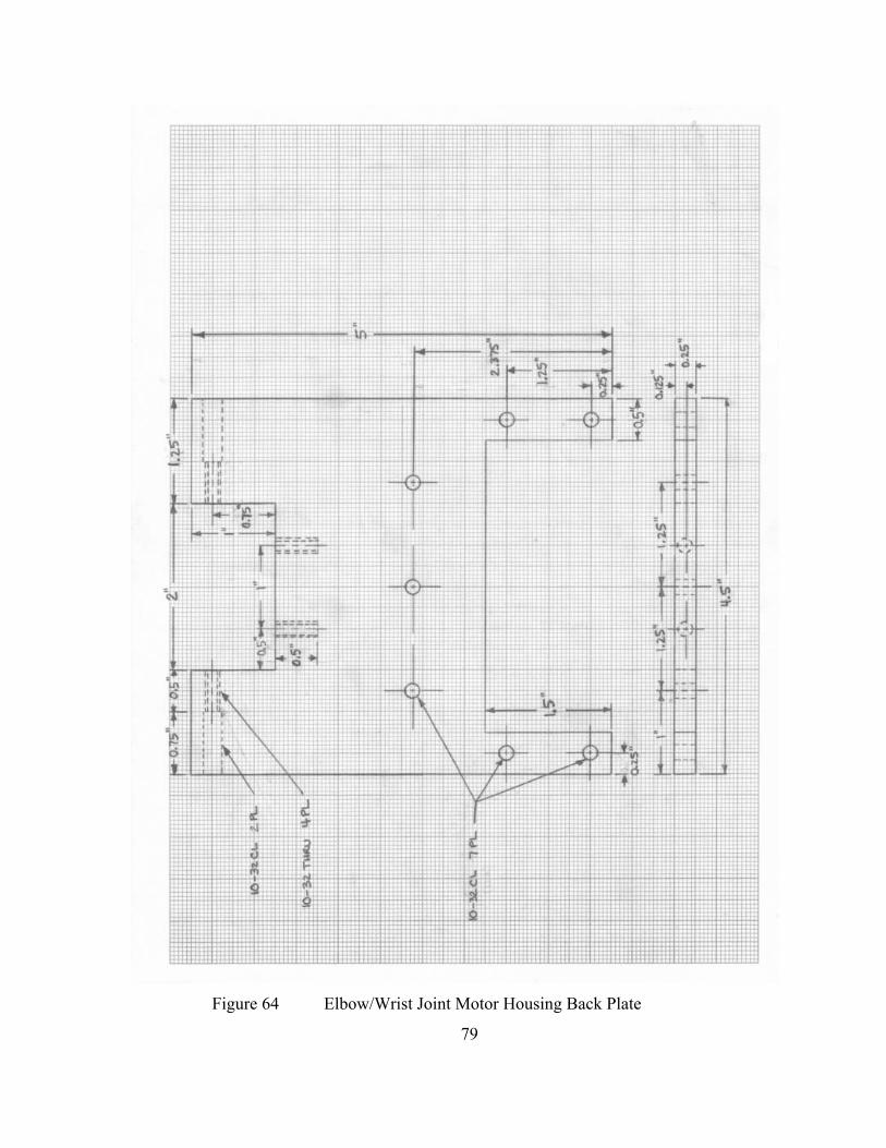
Figure 64 Elbow/Wrist Joint Motor Housing Back Plate
79
._(....L.;.,i..,.|....j:.,.|....,:.:.,..:4'-'.^'-.-i —''"-■T""i"--i—"■—I——-H-—.-—I —
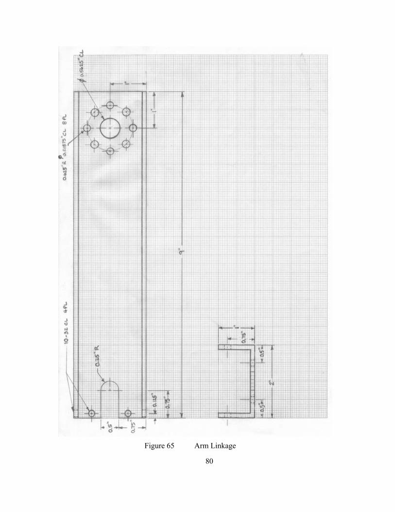
Figure 65 Arm Linkage
80
i T!TTT^''T"''T~"Tr!TTTT!TTFTTT7TTT^^
J ■*
J
■J
r
^
\
^
)+•
^ T Li
u
n c5 T7
J-Li.
^
r
o T I

APPENDIX B: WIRING SPECIFICATIONS
Due to the interaction of the various pieces of the motion control system, a
common wiring scheme was developed. Beginning with the two integrated wiring
harnesses (power and feedback) coming from the joint motors, the following figures and
tables provide the electrical path for each of the signals necessary to control the robotic
arms. Figure 66 illustrates the pin location (looking toward the pins on the male
connector, opposite numbering for the female receptacle) for the standard AMP
connectors used on the joint motors. The motor power cable uses AMP 206705-2 and the
feedback cable uses AMP 206152-1. Table 12 provides the pinout for the two cables
(Note: wire colors are not included, the first three motors were checked and a different
color scheme was used for each – the pins are standard though).
Figure 66 AMP Connector Pinouts
81

Table 12 Motor Connector Pinout POWER FEEDBACK
Function Pin # Function Pin #
Phase A 1 Hall Sensor 1 15
Phase B 2 Hall Sensor 2 19
Phase C 3 Hall Sensor 3 17
Shield/GND 5 GND 23
5V 22
Encoder A 9
Encoder A- 10
Encoder B 12
Encoder B- 11
Encoder I 13
Encoder I- 14
Shield 24
The electrical path for motor power (24 V) travels from the batteries, through the
isolation switches discussed in Chapter II, to the amplifier, and, finally, to the joint
motor. Table 13 provides the pinout of the harness connecting the servo amplifier and
joint motor power cable.
Table 13 Motor Power Cable to Amplifier Harness Pinout Function Wire Color Socket # Connects To
Phase A White 1 Motor A (amplifier)
Phase B Green 2 Motor C (amplifier)
Phase C Red 3 Motor B (amplifier)
Shield/GND Black/Shield 5 Grounding Screw (amplifier)
Further, in order to facilitate modularity and connection between components, a
series of harnesses were developed to break out the feedback lines needed by the UMI
and the amplifiers. Figure 67 shows the pin location of the MOLEX connectors used to
split the feedback path (again, looking toward the pins on the male connector, opposite
numbering for the female receptacle). Table 14 provides the wiring arrangement for the
82
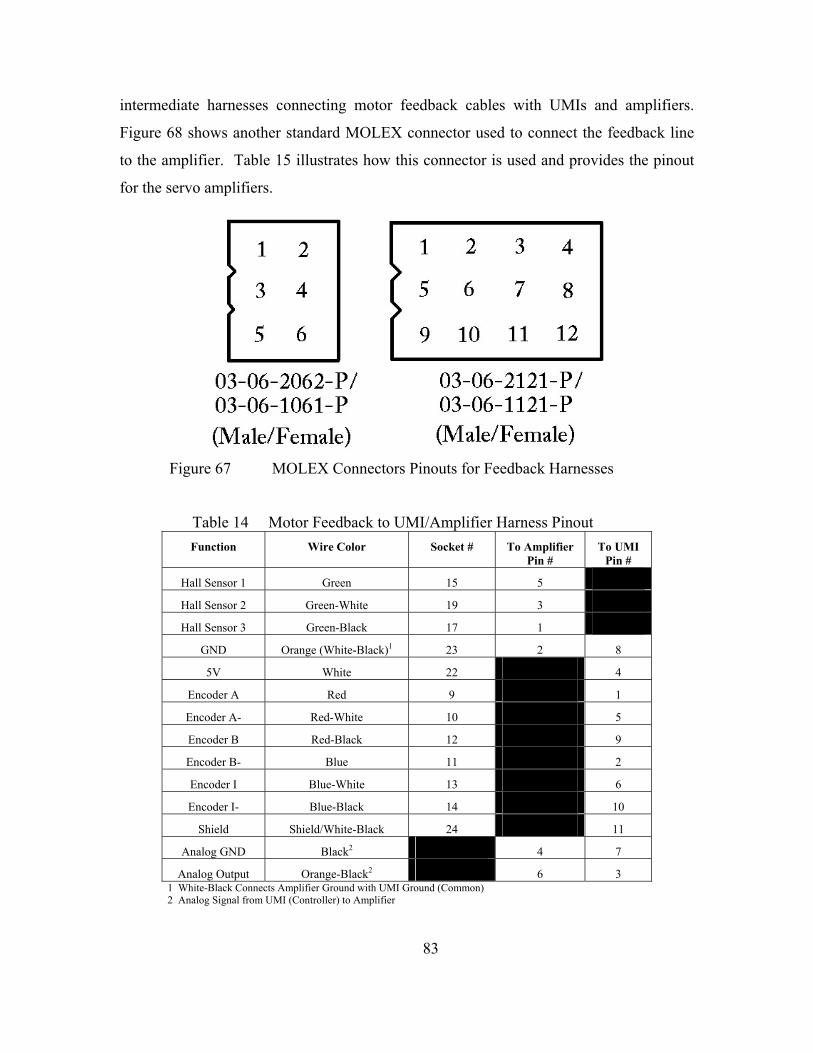
intermediate harnesses connecting motor feedback cables with UMIs and amplifiers.
Figure 68 shows another standard MOLEX connector used to connect the feedback line
to the amplifier. Table 15 illustrates how this connector is used and provides the pinout
for the servo amplifiers.
Figure 67 MOLEX Connectors Pinouts for Feedback Harnesses
Table 14 Motor Feedback to UMI/Amplifier Harness Pinout Function Wire Color Socket # To Amplifier
Pin # To UMI
Pin #
Hall Sensor 1 Green 15 5
Hall Sensor 2 Green-White 19 3
Hall Sensor 3 Green-Black 17 1
GND Orange (White-Black)1 23 2 8
5V White 22 4
Encoder A Red 9 1
Encoder A- Red-White 10 5
Encoder B Red-Black 12 9
Encoder B- Blue 11 2
Encoder I Blue-White 13 6
Encoder I- Blue-Black 14 10
Shield Shield/White-Black 24 11
Analog GND Black2 4 7
Analog Output Orange-Black2 6 3 1 White-Black Connects Amplifier Ground with UMI Ground (Common) 2 Analog Signal from UMI (Controller) to Amplifier
83

Figure 68 MOLEX Connector for Amplifier Pinout
Table 15 B12A6L Servo Amplifier Pinout Connector Pin Function Wire Color/Notes
1 +10V@3mA OUT NOT USED
2 SIGNAL GND White-Black (Ties to UMI GND)
3 -10V@3mA OUT NOT USED
4 +REF IN Orange-Black (Analog OUT from UMI)
5 -REF IN Black or Black-White (Analog GND from UMI)
6 -TACH IN NOT USED
7 +TACH/GND NOT USED
8 Current Monitor OUT
NOT USED
9 INHIBIT IN NOT USED
10 +V HALL OUT NOT USED
11 GND NOT USED
12 HALL 1 IN Green
13 HALL 2 IN Green-White
14 HALL 3 IN Green-Black
15 Current REF OUT NOT USED
P1
(Figure 68)
16 FAULT OUT NOT USED
1 MOTOR A White (Phase A)
2 MOTOR B Red (Phase C)
3 MOTOR C Green (Phase B)
4 POWER GND Grey (Terminal 6 or 11, Table 2)
P2
(Screw Terminals)
5 HIGH VOLTAGE Yellow (Terminal 5 or 10, Table 2)
84
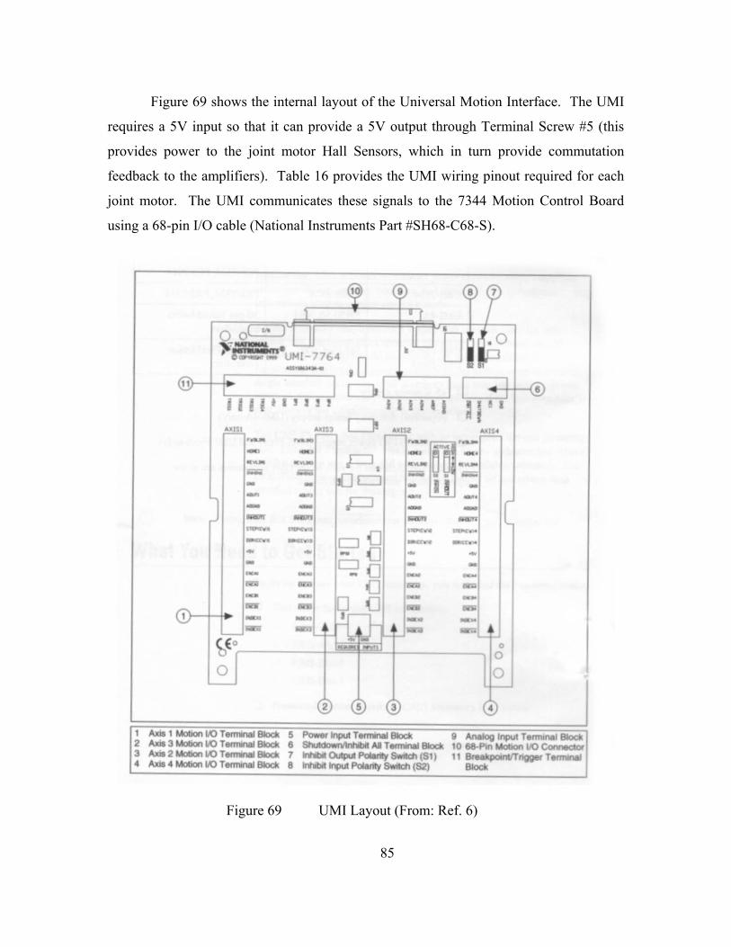
Figure 69 shows the internal layout of the Universal Motion Interface. The UMI
requires a 5V input so that it can provide a 5V output through Terminal Screw #5 (this
provides power to the joint motor Hall Sensors, which in turn provide commutation
feedback to the amplifiers). Table 16 provides the UMI wiring pinout required for each
joint motor. The UMI communicates these signals to the 7344 Motion Control Board
using a 68-pin I/O cable (National Instruments Part #SH68-C68-S).
Figure 69 UMI Layout (From: Ref. 6)
85
&■
ay
'o^^Pu
® ® ® @
VTirr- UMI-7764 .0 J 11 II * ■"> > ill M t JIM *(iti
J
E3 MIS3 I f itxne MIS* -1 "■■■II
O
O
o D G
I at AMI
II
® ® ®
c
O
o o
(i)
-d)
1 U«1MobonlX>T«rn*wlBloGfc S POMT Input TarrHnU Block 9 AnDog li^wl Ttnnlnal Bloc* 2 A]di3Ma«ianl«T*rmnalBlock 6 ShuMowMnMM Al Tammtf Blocfc 10 «8-PlnUallon UOConrwdor 3 A>ia2Mo«onK)TafmMIBIocfc 7 lrM)iOu«wlPoMlySMiltfi(Sl) 11 Bntf<pom^rtggw Ttnwttf 4 Axis 4 Mobon UO Temwul Block 6 InhiU Inpul PoMly 9«tth (SZ) Btocfc
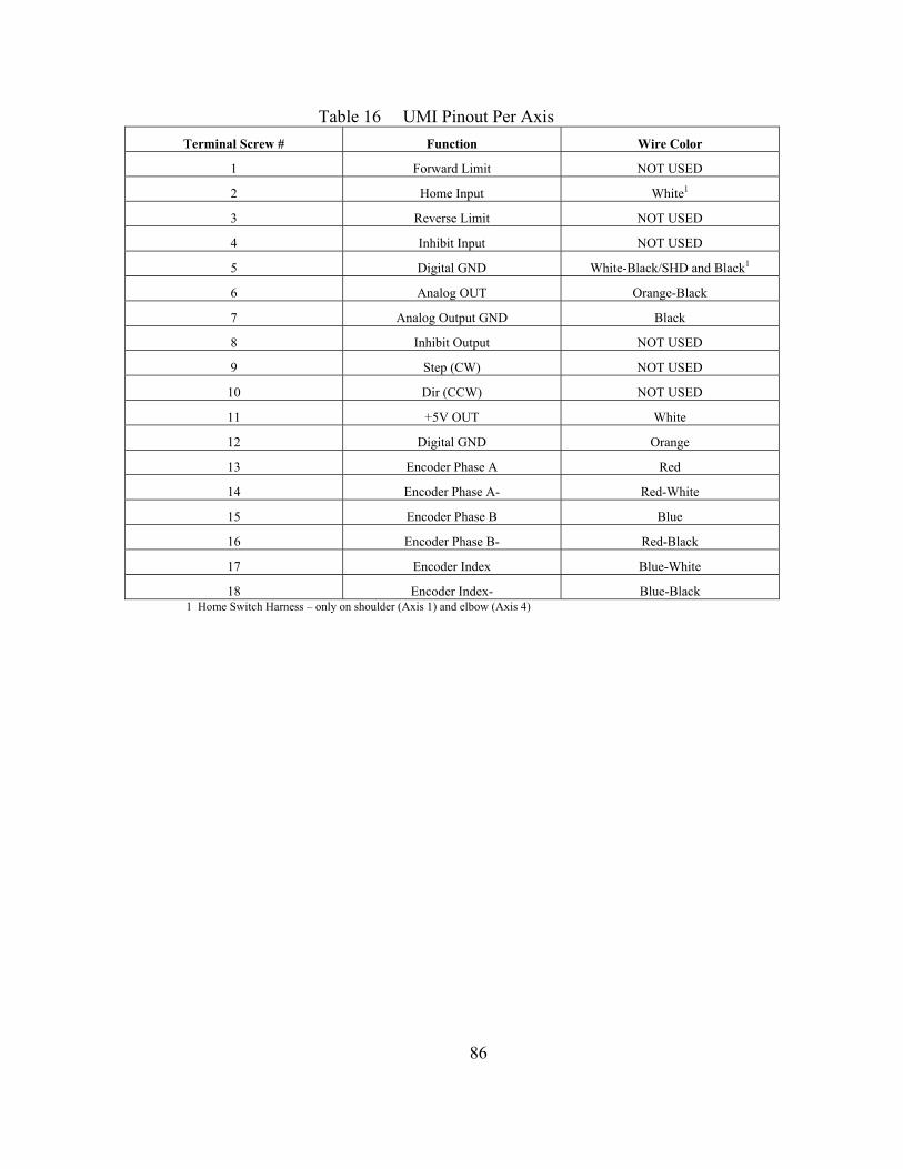
Table 16 UMI Pinout Per Axis Terminal Screw # Function Wire Color
1 Forward Limit NOT USED
2 Home Input White1
3 Reverse Limit NOT USED
4 Inhibit Input NOT USED
5 Digital GND White-Black/SHD and Black1
6 Analog OUT Orange-Black
7 Analog Output GND Black
8 Inhibit Output NOT USED
9 Step (CW) NOT USED
10 Dir (CCW) NOT USED
11 +5V OUT White
12 Digital GND Orange
13 Encoder Phase A Red
14 Encoder Phase A- Red-White
15 Encoder Phase B Blue
16 Encoder Phase B- Red-Black
17 Encoder Index Blue-White
18 Encoder Index- Blue-Black 1 Home Switch Harness – only on shoulder (Axis 1) and elbow (Axis 4)
86

APPENDIX C: MOTION CONTROLLER SETTINGS
A. DEFAULT 7344 SETTINGS
Table 17, on the following pages, provides a page by page listing of required
settings for 7344 Motion Controller initialization, using the Default 7344 Settings option
of the Measurement & Automation Explorer (MAX). These settings are utilized by either
arm. Not all settings are listed for every page. For those not listed, default values are
used. Formatting for the table as compared to the MAX interface is shown in Figure 70.
Figure 70 MAX Default 7344 Settings Definitions
87
Heading (bold, centered)
Mvitas and WHIACH
BMAQPXl-llOe;*B^
fii PX]-734ia)
:^ It Home Mndex $«(ta
[t. M ^"^ ^ Stftn^t
S ^ PWH MtAOb ^ii Intefactive
aQC4ttpratvi MlnflrxjiHrb
^lytifare
noteSydeitt
J 2i
AHisSeltirns
JAKSeHnp
OscfiAoa Cdtgneiltvi^anitifBwcalbCilbapivivgflnttiemaliDndnv
-EDGna
to lOOOO-r
^8kic^ FsHtwdc G w
/ Page Name setting Name (left column) (middle column)
Setting Value {right column)

Table 17 Default 7344 Settings Axis Configuration
Axis Type Servo
Axis Enabled 1 Enabled (1,3, and 4)
Disabled (2)
Encoder & Stepper Resolution
(Encoder counts per revolution)
Axis 1: 400,000
Axis 3,4: 200,000
Axis Resources & Update Period
(Control Loop Update Period)
188 microseconds
Axis Resources & Update Period
(Primary Feedback)
Encoder 1, 3, and 4,
respectively
Axis Resources & Update Period
(Primary Output)
DAC Channel 1, 3, and 4, respectively
Axis Resources & Update Period
(Secondary Feedback)
None
Axis Configuration
Axis Resources & Update Period
(Secondary Output)
None
Axis Settings
Home & Limit Switch Settings
(Forward Limit Switch)
Disabled
Home & Limit Switch Settings
(Reverse Limit Switch)
Disabled
Home & Limit Switch Settings
(Home Switch)
Enabled, Active Low Polarity
Software Limit Settings
(Forward Software Limit)
Axis 1: Disabled
Axis 3: Enabled, 60,000 counts
Axis 4: Enabled, 66,000 counts
Software Limit Settings
(Reverse Software Limit)
Axis 1: Disabled
Axis 3: Enabled, -60,000 counts
Axis 4: Enabled, -66,000 counts
Motion I/O
Inhibit Output Settings Disabled
Control Loop ALL VALUES See Table 18 for values from Calibration/Servo Tune
Load Torque Limits & Offsets in: Volts
Primary DAC Output
(Positive Torque Limit)
10 Volts
Miscellaneous
Primary DAC Output
(Negative Torque Limit)
-10 Volts
88
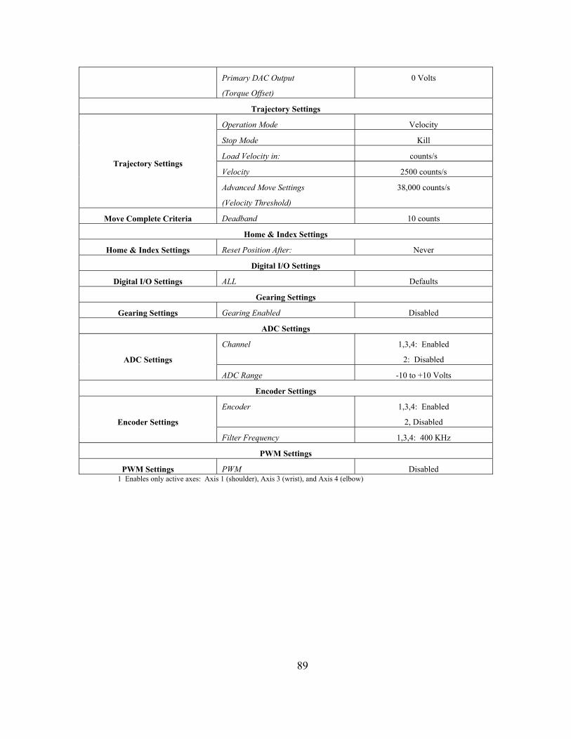
Primary DAC Output
(Torque Offset)
0 Volts
Trajectory Settings
Operation Mode Velocity
Stop Mode Kill
Load Velocity in: counts/s
Velocity 2500 counts/s Trajectory Settings
Advanced Move Settings
(Velocity Threshold)
38,000 counts/s
Move Complete Criteria Deadband 10 counts
Home & Index Settings
Home & Index Settings Reset Position After: Never
Digital I/O Settings
Digital I/O Settings ALL Defaults
Gearing Settings
Gearing Settings Gearing Enabled Disabled
ADC Settings
Channel 1,3,4: Enabled
2: Disabled ADC Settings
ADC Range -10 to +10 Volts
Encoder Settings
Encoder 1,3,4: Enabled
2, Disabled Encoder Settings
Filter Frequency 1,3,4: 400 KHz
PWM Settings
PWM Settings PWM Disabled 1 Enables only active axes: Axis 1 (shoulder), Axis 3 (wrist), and Axis 4 (elbow)
89

B. SERVO TUNE GAINS
As described in Chapter III, MAX was utilized to manually tune the six brushless
servo joint motors, the required gains were identified for each. Table 18 lists these gains
identified for stable operation of the joint motors. Once established in Servo Tune, these
values automatically save to the Default 7344 Settings/Axis Settings/Control Loop page,
allowing proper initialization at power-up.
Table 18 PID Control Gains for NPADS Robotic Arms Left Arm Kp Kd Ki Td Right Arm Kp Kd Ki Td
Shoulder 25 275 0 2 Shoulder 50 600 0 2
Elbow 85 355 0 2 Elbow 15 160 0 2
Wrist 85 330 0 2 Wrist 50 250 0 2
As mentioned in Chapter III, MAX also contains routines to produce Step
Responses, Bode Plots, and Trajectory Responses. Figure 71, Figure 72, and Figure 73
provide examples of each of these tools, respectively, for one of the joint motors. Due to
the low speed, high torque operation expected of the joint motors, Step Response was the
primary driver of the tuning process. Adjusting the gains allowed for minimization of the
Maximum Overshoot and Settling Time, ensuring optimum performance and limited
vibration of the motors.
90
jMjn c3 s^RiiF»ld II*»T| a ■BWTO a*w"*l
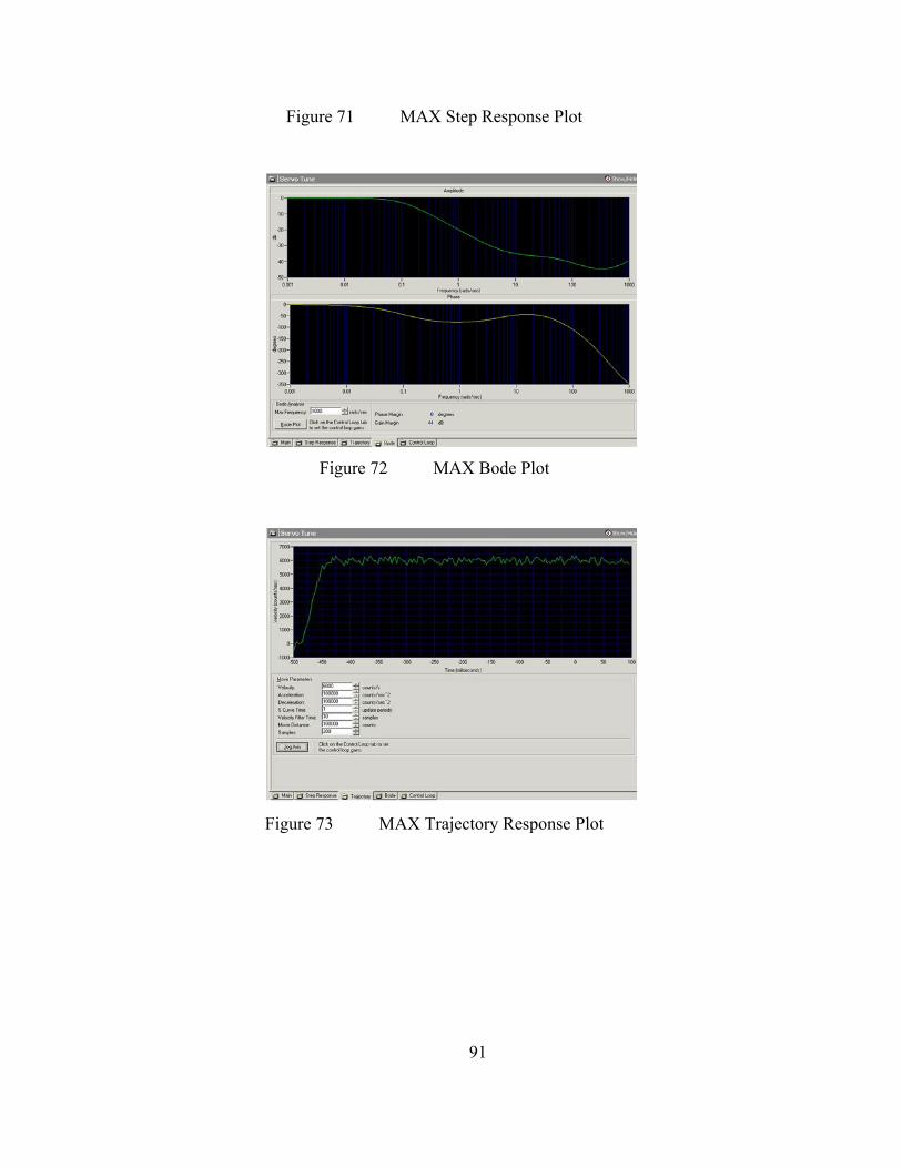
Figure 71 MAX Step Response Plot
Figure 72 MAX Bode Plot
Figure 73 MAX Trajectory Response Plot
91
aD-i
UD- ■^H ̂ ^^H ̂ ^^^^H ̂ ^^^^H ^^^B^^^^^^B ^^^^^^H ^^^H ^^^^^^^^^^^^^^^^^1 ^^^^^^^^^^^^^^^^^H
«flH
ixpH^ ^^^^^^^^^^^1 ^^^^^^H ^^^1 ^^^^^^^^^^^^^^^^^1 ^^^^^^^^^^^^^^^^^H ^^^^^1 ̂ ^H ■ 1:0:0- ^^^^^^^^^^^^^^1 ^^^^^^^^^^^^^^1 ^^^^^1 mi ^^^^^1 ̂ ^H ^^^^^^^^^^^^^^1 ^^^^^^^^^^^^^^1 ^^^^^^^^^1 ■ ̂̂̂^^^^^1 ̂ ^^^^^^^1
^ 3 *» -■» » Q » j» m iw » 0 S IW
«*i°V Ui^ -■ iwcr ^
Dflrtw« iVAOJ -■ ADnalH ■h
VlK*>h>TfW i<^ ■;
-i [f^gi EsSS:^."—"-
& Mml J WPWMP** a I'*™—fd~*^l JIJ-dLMil

THIS PAGE INTENTIONALLY LEFT BLANK
92
LIST OF REFERENCES
1. Yoshida, Kazuya, “Space Robot Dynamics and Control: To Orbit, From Orbit,
and Future,” presented at the International Symposium on Robotics Research, 9th,
Snowbird, Utah, October 1999.
2. “The Special Purpose Dexterous Manipulator (SPDM),”
[http://www.space.gc.ca/csa_sectors/human_presence/iss/contribut/mss/spdm/def
ault.asp], 17 September 2001.
3. “Robonaut,” [http://vesuvius.jsc.nasa.gov/er_er/html/robonaut/robonaut.html], 05
February 2001.
4. Porter, Robert D., Development and Control of the Naval Postgraduate School
Planar Autonomous Docking Simulator (NPADS), Master’s Thesis, Naval
Postgraduate School, Monterey, California, September 2002.
5. Harmonic Drive Technologies Motor Specifications, PowerHubTM Harmonic
Drive Servo Actuator, February 2000.
6. National Instruments, Universal Motion Interface (UMI) Accessory, August 1999.
7. National Instruments, Motion Control: 7344/7334 Hardware User Manual,
August 2001.
8. National Instruments, IMAQ: IMAQ PCI/PXITM-1408 User Manual, October
1999.
9. National Instruments, PXITM: PXI-8150B Series User Manual, February 1999.
10. National Instruments, “Understanding Servo Tune,”
[http://zone.ni.com/devzone/conceptd.nsf/webmain/4B7775373E4AE64986256B
6000691505?opendocument], 2002.
11. Chen, Chi-Tsong, Analog and Digital Control System Design: Transfer Function,
State-Space, and Algebraic Methods, pp. 69-102, Harcourt Brace Jovanovich
College Publishers, 1993.
93

THIS PAGE INTENTIONALLY LEFT BLANK
94

INITIAL DISTRIBUTION LIST
1. Defense Technical Information Center Ft. Belvoir, Virginia
2. Dudley Knox Library Naval Postgraduate School Monterey, California
3. Department Chairman Department of Aeronautics and Astronautics Monterey, California
4. Department of Aeronautics and Astronautics Professor Michael G. Spencer Naval Postgraduate School Monterey, California
5. Department of Aeronautics and Astronautics Professor Brij N. Agrawal Naval Postgraduate School Monterey, California
6. Department of Aeronautics and Astronautics SRDC Research Library Naval Postgraduate School Monterey, California
7. LT Gary L. Cave, USN West Palm Beach, Florida
95


