
Report No. FAA-RO-79-75
THE SELECTION OF GLIDE SLOPE ANTENNA PATTERNSFOR USE IN THE FREQUENCY ASSIGNMENT PROCESS
Mark Lopez
/
of YT4
O ' AUG
July 1919U Final Report
Document is available to the U.S. publ'c throughthe National Technical Information Service,
Springfield, Virginia 22161.
Prepared for
U.S. DEPARTMENT OF TRANSPORTATIONFEDERAL AVIATION ADMINISTRATION
Systems Research & Development ServiceWashington, D.C. 20590

NOTICE
This document is disseminated under the sponsorship of theDepartment of Transportation in the interest of in'ormationexchange. The United States Government assumes no liabilityfor its contents or use thereof.

Technivel Report Oecumentation Pegs
2 Govem. no, Acc ston No 3. Recipient' .atelog No.
4. T,,lo and SubtitleThe Selection of Glide Slope Antenna Patterns Ju -79
Use in the Frequency Asfignment Process. ,ion Code
I .. -' *j;.t.t',. 0______________ . P =ft 40
P. foiiin o onsomastion Nomie and Akdd,, 10 wo'door 0f 9
Federal Aviation AdministrationSystems Research and Development Service 1I Cont.oct or Giant NoSpectrum Management Staff, ARD-60AT Spectrum Engineering Branch, ARD-62 13 Type of Report end Pe' r.NJ&
U.S. Department of Transportation, FinalFederal Aviation AdministrationSystems Research and Development ServiceWashington, 0. C. 20591 - -
15 Suppltmelertey Not**
-16 Abtract
The trequency assignment process is meant to preclude harmful interferencewithin servic'- volumes. This is done by choosing frequencies in a mannerwhich provides certain a',imum cochannel and adjacent channel desired toundesired signal ratios a; critical points of the service volume. One of thefactors which affects a stations signal strength in space is its horisontalantenina pattern. Consequently, the horizontal pattern can have a substkntillettect onthe separation required between glide slope frequency assignments. Insome cases, it is desirable to consider the actual antenna patterns involvedrather than using woratcase station separations. This report has been assembledso that the directivity of the horizontal pattern may be considered in theassignment process. For each antenna type, a particular antenna pattern isrecommended.
PK+ *oruOritributlrn StO.#I.m n
i-strusear Landing System (11,S) Document is available to the publicCl id,, Slopr, through the National Technical InformationAnt vnas Service, Springfield, Virginia, 22151.l'i equency Management
19 sot~oti Ooss$, Qft hts fooort, 20, Nocurtlj clossit. tof;I this e) 21. Nr' o . 2 Pr ice
K Unclassi i~d Unclassitied 90
Fotm DOT F 170.7 , Roproduction of coTPletd Page outhorwted
ii AS

FEDERL AVIATION ADMINIS TTONSSTSZ SEAC N DEVELOPMENT SERVICESMANGEMENT STAFF
The mission of the Spectrum Management Staff is to assist theDepartment of State, National Telecommunications and Informa-tion Administration, and the Federal Communications Commissionin assuring the FAA s and the nation's aviation interests withsufficient protected electromagnetic telecommunicationsresources throughout the world and to provide for the safeconduct of aeronautical flight by fostering effective andeff'cient use of a natural resource - the electromagnetic radiofrequency spectrum.
This objective is achieved -hrough the following services:
. Planning and defending the acquisition and retention ofsufficient radio frequency spectrum to support the aero-nautical interests of the nation, at home and abroad,and spectrum standardization for the world's aviationcommunity.
. Providing research, analysis, engineering, and evalua-tion in the development of spectrum related policy,planning, standards, criteria, measurement equipment,and measurement ,tchniques.
* Conducting electroma&netic compatibility analyses todetermine intra/intersystem viability and design para-meters, to assure certification of adequate spectrumto support systoo operational use and projected Srowthpatterns, to deteld aeronautical services spectrumrow encroachmt.%- by others, and to provide for the
efficient use of the aeronautical spectrum.
0 Developing autcmated frequency selection computerp rograms/routir es to provide frequency planning,
frequency assignment, and spectrum analysis capabili-ties in the spectrum supporting the National AirspaceSystem.
a Providing spectrum management consu'tation, assistance,and guidance to all aviation interests, users, and pro-viders of equipment and services, both national andinternational.
ii

FEDERAL AVIATION ADMINISTRATIONSYSTEMS RESEARCH AND DEVELOPHENT SERVICE
SPLCTRUM MANAGEMENT STAFF
STATEMENT OF MISSION
The mission of the Spectrum Management Staff is to assist theDepartment of State, National Telecommuunications and Informa-tion AdministrationI and the Federal Communications Commissionin assuring the FAA s and the nation's aviation interests withsufficient protected electromagnetic telecommunicationsresources throughout the world and to provide for the safeconduct of aeronautical flight by fostering effective andeff:cient use of a natural resource - the electromagnetic radiofrequency spectrum.
This objective is achieved .hrough the following services:
Planning and defending the acquisition and retention ofsufficient radio frequency spectrum to support the aero-nautical interests of the nation, at home and abroad,and spectrum standardiza:ion for the world's aviationc otrimu n i ty.
Providing research, analysis, engineering, and evalua-tion in the development of spectrum related policy,planning, standards, criteria, measurement equipment,and measurement techniques.
Conducting electrom.,bnetic compatibility analy'ses todetermine intra/intersy'stem viability and design para-meters, to assu-e certification of adequate spectrumto support systco, operational use and projected growthpatterns, to det'ad aeronautical services spectrumfrow encroachmt-." by others, and to provide for theefficient use of the aeronautical spectrum.
Developing autcmated frequency selection computerprograms/routires to provide frequency planning,frequency assignment, and spectrum analysis c abili-ties in the spectrum supporting the National AirspaceSystem.
Providing spectrum management consu'tation, assistance,and guidance to all aviation interests, users, and pro-viders of equipment and services, both national andinternational.
II

TABLE OF CONTENTS
Page No.
INTROD UCTION -.......................................................... 1
DISCJSSSION ----------------------------------------------------------- 3
CONIUcSIONS ---------------------------------------------------------- 5
RECOMMENDED ANTENNA PATTERNS ------------------------------------------ 6
RELATED DOCUMENTS ----------------------------------------------------- 13
ACRONYMS AND ABBREVIATIONS -------------------------------------------- 17
APPENDIXES
A. TYPE I and TYPE II Antennas
B. TYPE III and TYPE IV Antennas
C. 2-Lambda Cassegranian Antenna
D. Stan-38 Antenna
E. End - Fire Slotted Cable Antenna
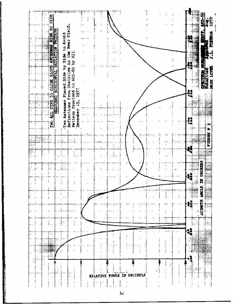
F. AIL Type 55 Antenna
G. FAA Antenna Specifications
H. Original NAFEC Data
I. Photographs of Different Antenna Types
'V
INTRODUCTIO4
In the past, separation of frequency assignments for associated facilities
has not considered the individual system components. Consideration of these
components (VOR, DNE, TACAN, LOCALIZER, GLIDESLOPE) had been included in the
overall separation criteria. Separations required between VOITAC Stations did
not require that VOR and TACAN separations be considered separately. Separations
required between ILS stations did not require that LOCALIZER, GLIDESLOPE, and
MEM separations be considered separately. Years ago, there was enough standard-
isation among facilities that this could be done. In recent years, however, the
use of many stations types and the variation in the radiated powers of stations
has lead us to reexamine old assumptions and conclusions. As a result of this
examination, we have concluded that separation of frequency assignments for
associated facilities should consider the individual system components.
The use of directional antennas can have a substantial effect on the
separation required between ILS Localizer frequency assignments. Since
cochannel separations are larger, the effect will be greater for them than for
adjacent channel separtions.
V Consideration of horizontal glide slope antenna directivity is not expected
to have a substantial effect on the separation required between cochannel ILS
systems. Since the glide slope service volume is substantially smaller than
the localizer service volume, localizer separation requirements are still ex-
pected to dominate in almost all circumstances. A similar statement could be

made for those first adjacent channel glide slope which are paired with first
adjacent channel localizers (example: 18x and 18y).
The situation is somewhat different for second adjacent channel glide
slope stations and for those first adjacent channel glide slopes not paired with
first adjacent channel localizers (example: 18y and 38x). In these cases,
the glide slope separation requirement must naturally be examined individually.
The horizontal antenna patterns of the glide slope antennas may have a sign-
ificanc effect on separation required in these cases. Consideration of the
antenna pattern may be preferable to using worst case separations.
We have assembled data from a number of sourc.s. For antenna type where
horizontal patterns were not available, we have made use of NAFEC's ability
to measure them. Wherever possible, comparisons have been made between the
following types of information:
Theoretical Antenna Patterns
Measured Antenna Patterns
- Applicable FAA Antenna Specifications
Data for each antenna type is included in the appendixes. On the basis
of these data, antenna patterns have been chosen for use in the frequency
assignment process. These patterns are shown in the report conclusions.
2

DIS(ISSIO4
Itionale for Antenna Pattern Choices
from the Information available, three types of antenna data have been
compared: theoretical, measured, and FAA Specifications. Ideally, agreement
would be expected among these types of data. Practicallyo this is not always
the case. For some antennas, all three types of data are not available. In
reviewing what was available, we used the following general glide lines in
choosing horisontal antenna patterns for the frequency assignment process.
If an FAA Antenna Specification was found to be applicable
for an antenna type and if both the theoretical and the
measured data compared reasonably well with it, we depended
largely on the specification in choosing the pattern to
be used in the frequency assignment process.
If an FAA Antenna Specification was found to be applicable
and it did not compare well with the measured data, we chose
a conservative frequency assignment pattern based on - cars-
fully chosen mixture of specification and measured data. An
example of this method is seen in the frequency assignment
pattern chosen for the type I and type I antennas.
If no FAA Antenna Specification was applicable and if
theoretical data was only available for some portion of
a pattern, we tried to get as much measured data as possible
before choosing a conservative pattern.
If no FAA Antenna Specification was found to be applicable

and if no tLeoretical pattern yes available, we chose
a frequency asseSgment pattern on the basis of the measured
data. The patterns chosen for the Stan-38, End-Yirs Slotted-
Cable, end the A.I.L. Type 55 Glide Slope Antennas are exaples
of this method.
41

ca N=SIoNS
1. The difference between the horizontal antenna patterns of various 118
glide elope antenna types are not as large as what has been found for
118 localisers. Nevertheless, some differences are apparent. In some
cases, it my be desirable to take these differences into account in the
frequency assignment process.
2. Uecomended antenna patterns are shown in figures 1 thru 7. These
patterns are t.ntended as tools for avoiding interference between LS
glide slopes. In some cases, those are not the best patterns to use as
tools for avoiding interferences between ILS glide slopes and other types
of radtu aervices. Should the need arise to make such an analysis, dis-
cussion with the Spectrum Management Staff (ARD-60) is recominded.
3. A frequency assigment antenna pattern is not included for the wave-
glide antenna since no horisontal antenna patterns were found. Antenna
data on this system is therefore still required. Additional data would
also be helpful on the A.I.L. Type 55 glide slope and the end-fire
slotted cable system.
5

, ;..... ' a91 ill:~f ~~11 111..
-,
.. . "" . .
77 7
, I.., I
~t t
I' . '_, ',.9 - , ,,
9.9 "
RE IVE ANTENNA GAIN IN DECIBES
I t i.
9 , -.

4 4*,I..~.4
49- -EjI ;!I
1. Ii III
LJW,~74 771--
7nt
.. . .. ....
'' - - .: . -. .] 1 , ., ' il
411
I i.

-Trr. r" r i rrMTM 7
+4;' 4;
tilt Tr -- I --- I +
P 11 :17 VI-
_;TT ;J..
+ 41:1 to'
+ TT
u4, i"+
'tit il"i "i", iii.1': 7 ... .. . I"T I
.0- titT IT:14
to
I T
lee)I- ;,.:" 1 _ + 4 -r 7I. .... ....
10 i it I I.,:... .... ...
7,1
... .... .... .. .
it
!t::::lot
It I
it, toTT
to ;It oil
it t i GAIN IN DERZIATIVE ANTZWNA

,' , I I , " .. .*- -T
* I .
I- '
... 4
,A I I
II 1 oULATVE ATKNN GAN INDI CB£,
Hi
44 7 4
101

--44 44
1.4
'41111114T.
+ M
4
Tr. ' 147T
+I lq:::. - :- . - t: : l n.. - . -
11+11 1:; :4.;,;- 134lw +
77 't_ z:F 7-
-T+ -t 11 4 T44, ;!-; l-,;lrT,,-t-,TT4c V
44!- t : . -- : , -1 .1 1: 1 : I I ... .. .. .. ..
R 77 77 .... ....4c
.7-, .7*
1 '17 7
-41.. .. .. . . . ..
co ......
U %
cr-
+:
6-
T 1--4-44
ii,4
:7
:+
1-4 1
j4 +41
-7- 77-
.. ... .....
44
til-
T +I;
:+ T
x Ila
4j+ REIATIVE ANTENNA GAIN IN DECIBELS
11111111110 llo +i

K* I
-f-4
I -,4
tEATV A*-FM GINI PIMIQr

MEIkTZD DOtWNTS
1. FAA Handbook 6050.5A, "Frequency Management Engineering Principles,
Geographical Separation Criteria for VOR, DKE, TACAN, ILS, and VOT
Frequency Aesinments," March 12, 1969.
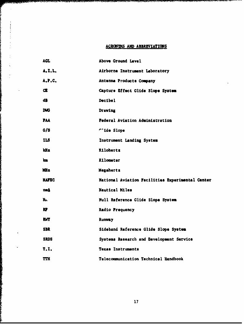
2. FAA Instruction Booklet TI 6750.9, "Antenna, Glide Slope Type FA-80900"
FAA Contract FA68WA-1969, Scanwell Laboratories Inc., May 9, 1968.
3. Wilcox American Standard Co., Instruction Book TI 6750.21, "Glide Slope
Antenna (Type III) Type FA-8021," FAA Contract FA68WA-1890, Wilcox
American Standard Co., April 30, 1968.
4. FAA Preliminary Instruction Book TI 6750.32, "Glide Slope Antenna
System Type FA-8730," FAA Contract DOT-FA704-2451, Scanell Laboratories
Inc.. June 30, 1970.
5. FAA Preliminary Instruction Book TI 6750.44, "Glide Slope Antenna System,
Part of Mark I Instrument Landirl System," FAA Contract DOT-FA69WA-2196,
A,I.L. Cutler Haomer, June 30, 1969.
6. FAA Preliminary Instruction Book TI 6750.63, "Glide Slope Antenna System
Type FA-8870,' FAA Contract FA71WA-2525, Scanvell Laboratories Inc.,
December 30, 1970.
7. FAA Instruction Book, Book I TI 6750.69, "Glideslope Station, One
Frequency Type AN/GRN-27(V)6" FAA Contract F33657-71-C-0103, Texas
Instrumenta, June 1, 1974.
8. FAA Instruction Book, Book I TI 6750.70, "Glidealope Station, Two
frequency Type AN/GRN-27 (V)," FAA Contract F33657-71-C-0103, Texas
Instruments, June 1, 1974.
13

9. FA Instruction Book T16750.76, "Gldo. Slope Antenna System FA-8976,"
F M Contract FA73WA-3176, February 9, 1973 and FA73WA-3358, Antenna
Products Co., October 16, 1973.
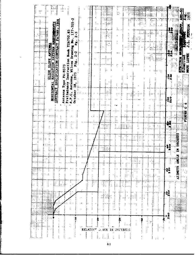
10. FAA Preliminary Instruction Book T16750.83, "Glide Slope Antenna Type
FA-9373," FAA Contract FA74VWA-3364, Antenna Products Co., October 18, 1973.
11. FA Instruction Book, '"Krk III Instrument Landing System Glide Slop*
Station NAPIC," FAA Contract DOT-FA73WA-3289, Texas Instrusents.
12. FAA Order 6750.6B, "Installation Instructions for Category I and
Category II ILS Glide Slopes," July 9, 1976.
13. FAA Order 6750,16A, "Sitting Criteria for Instrument Landing Systems,"
August 18, 1973.
14. FAA Order 6750.17, '"aintenance of ILS Glide Slope Equipment," August
25, 1971, Reprinted September 14, 1976 (Includes Changes 1 through 4).
15. FA Order 6750.32, '"aintenance of Null Reference Glide Slope Equipment,"
August 9, 1976.
16. FAA Report No. RD-64-11 "Analysis of ILS Glide Slope Antennas in
Operation and Under Development," FM Contract FA-WA-4391, National
Engineering Science Co., February 1964.
17. FA Report No. RD-65-46," A Waveguide Glide Slope Antenna," FM Contract
FAA/BRD-317, A.I.L. Cutler Hamer, July 1965.
18. FAA Report No. FM-RD-71-30," Instrument Landing System Improvement
Program," FAA Contract FA69WA-2066, Avionics Research Group, Department
of lectrical Engineering, October 1971.
19. FAA Report No. FAA-RD-72-139, "Analysis of Instrument Landing System
Glide Slope Broadside Antennas," FAA Contract DOT-FA71WA-2666, Aerospace
14

#ad Electronics System Division of Westinghouse Defense and Slectromics,
~.Sys tem Center, August 19 72. F.D7.6 MdiiainadTa
Instuma Ladin SyteaGlie SopeWavguie Atena,"FAAContract
21 DQ-PA7lA-2666. Asrospece and Electronic* System Division of Westinghouse
Defense and Ilectconic System Centetr, June 1973.
22. FAA ItmRep No. FR-D-76, "The Sltion fd Test Lofe teu
Patterns for use in the Frequency Assignment Prftess." Robert D. Smithq
September 1978.
23. FAA Specification FAA-3-2245, 'Antennass Glide Slope," March 11, 1966,
Amndmnt-3. March 24, 1969.
24. FAA Specification FM.E9-2429, "Antenna System, Glide Slope." January 2,
1970, Aaenduene-2, November 14, 1973.
25. FAA Specification FAA--2557, "Amplitude and Phase Control Unit, Sideband
Reference Glide Slope," April 2, 1973. Amndwent-l, Key 11. 1973.
26. Photographs Obtained from Robert Littlepage, Program Manager, Glide Slope
Antenna Systems, Westinghouse Electric Corp., Letter To ARD-60 Dated
December 20, 1977.
27. Scenvell laboratories, Inc., "Instruction Manual for Glide Slope Antenna
System Type 4400," Prepared for Pueblo Memorial Airport to Serve Ruvay
25R. July, 1970.
15

28. Technical Manual TT1 309, "Instrument Landing System Equipment Glide Path
Type Stan 38,"1 British Docummtt HB. 1268/2-A Issue 1, June 1968.
29. Unpublished Measured Data Obtained from Neil Creedon, A.I.L. Cutler
Haamumer, Latter To ARD-60 Dated December 19, 1977.
30. Watts Jr., C.B., "Description of the End-Fire Slotted-Cable Glide Slope,,
Medium Aperture," January 1977.
16
I
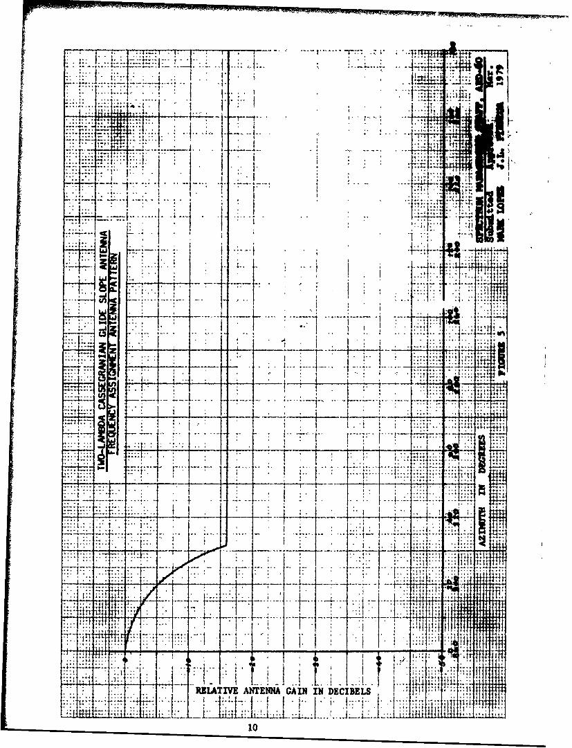
ACRK W AND AIIREVIATIONS
AGL Above Ground Level
A.I.L. Airborne Instrument Laboratory
A.P.C. Antenna Products Company
CE Capture Effect Glide Slope System
dl Decibel
DAA Drawinl
FAA Federal Aviation AdmSnlotrateon
I/S "nride slope
kLS Instrument Lnding System
kHs Kilohertz
k. Kilometer
MRC ieEahertz
NAC National Aviation Facilities perimental Center
na Nautical fele e
RNull Reference Glide Slope Sstem
Y Radio requency
IY Runway
SBR Sidebmnd Reference Glide Slope System
SRDS Systems Research end Development Service
T.1, Texas Instruments
TTH Telecommunication Technical Handbook
17

APPENDIX A
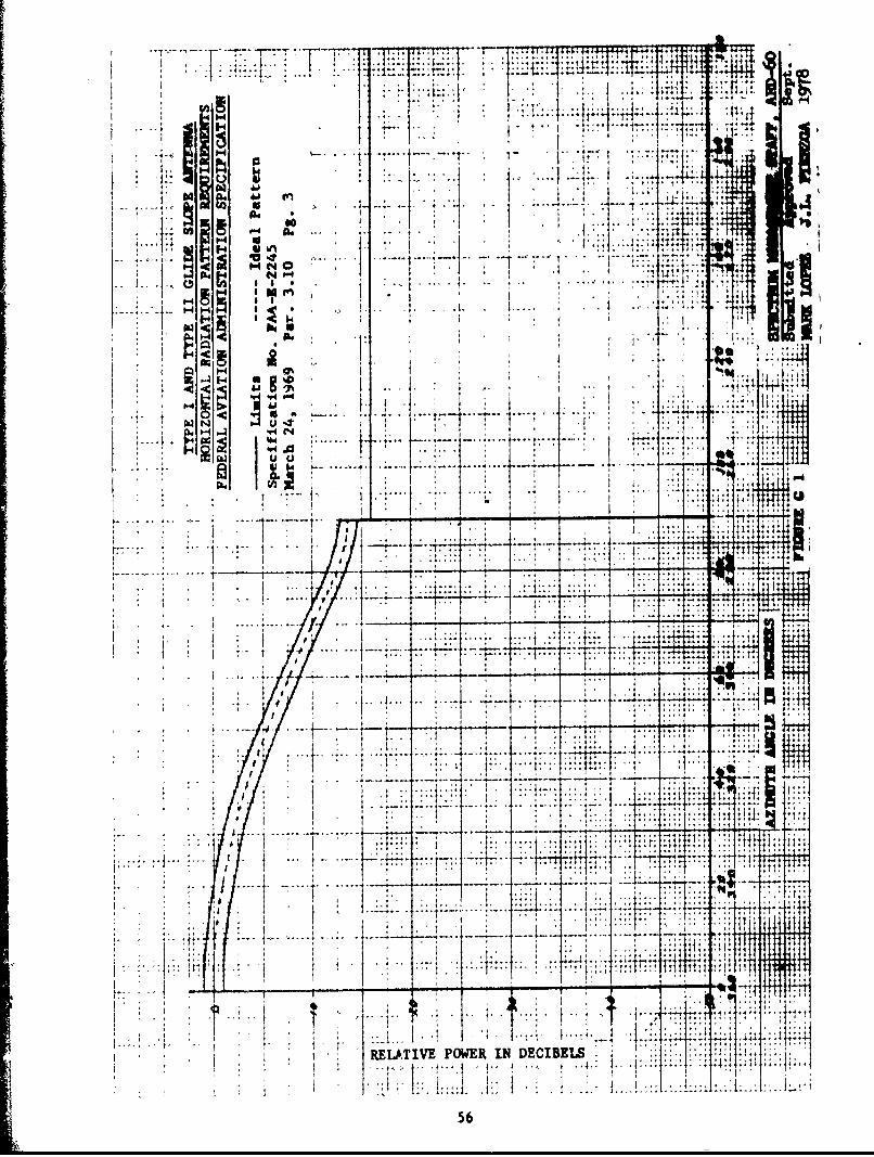
TYPE I AND TYPE 11 ANTENNAS
The Type I antenna consists of a half - wave dipole mounted on an
elliptical ground plane and enclosed in a radome. The Type II antenna is
the same as the Type I, except it is equipped with a heater. The addition
of the heater does not affect the antenna pattern. These antennas have
primarily been used with the older tube type transmitters. They are grad-
ually being phased out in favor of antennas with a more directional azimuthal
pattern. Only limited measured data was found on these antennas.
The measured data taken at NAFEC (Fig. AD) compares well with the
theoretical patterns. In addition, it compares reasonably well with the
requirements of specification FAA-E-2245 (&Hg. GI). The measured data from
Trenton (Fig. A4) does not compare quite as well. The main lobe of the
pattern is somewhat narrower and the pattern slightly exceeds the -16dB
limit between 242 and 264 degrees. No explanation was available f, r these
discrepancies. Tht frequency assignment antenna pattern recomrended for the
Type I and Type II Glideelope Antennas (Fig. 1) is based on the specification
(FAA-E-2245) and figures in Appendix A.
18

T % --- --
I... ....
.:77
- -~ ~ ..... ...* ** ** . : .. . . ....
I:.E:
7::~ -. li-
:y;44. 4
it rt -. .
REA M PWR (DC S . ..... . .. .
19
77: EE4:
l2f

44
jH I:
64
-- -- W 4
10 U7h -4....... ...C167V
7-: .T
-7Li ttWL it

- , - ~1ThW4
K W 0%
I.j
~~jihHL~,47~j V~~4 .. us
ID-.. 4K
rL'D
I- .0.6-
o i: ~ ~
REATV ANENGI I ECBL
11 Vi
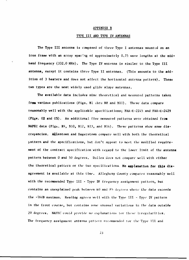
APPENDIX B
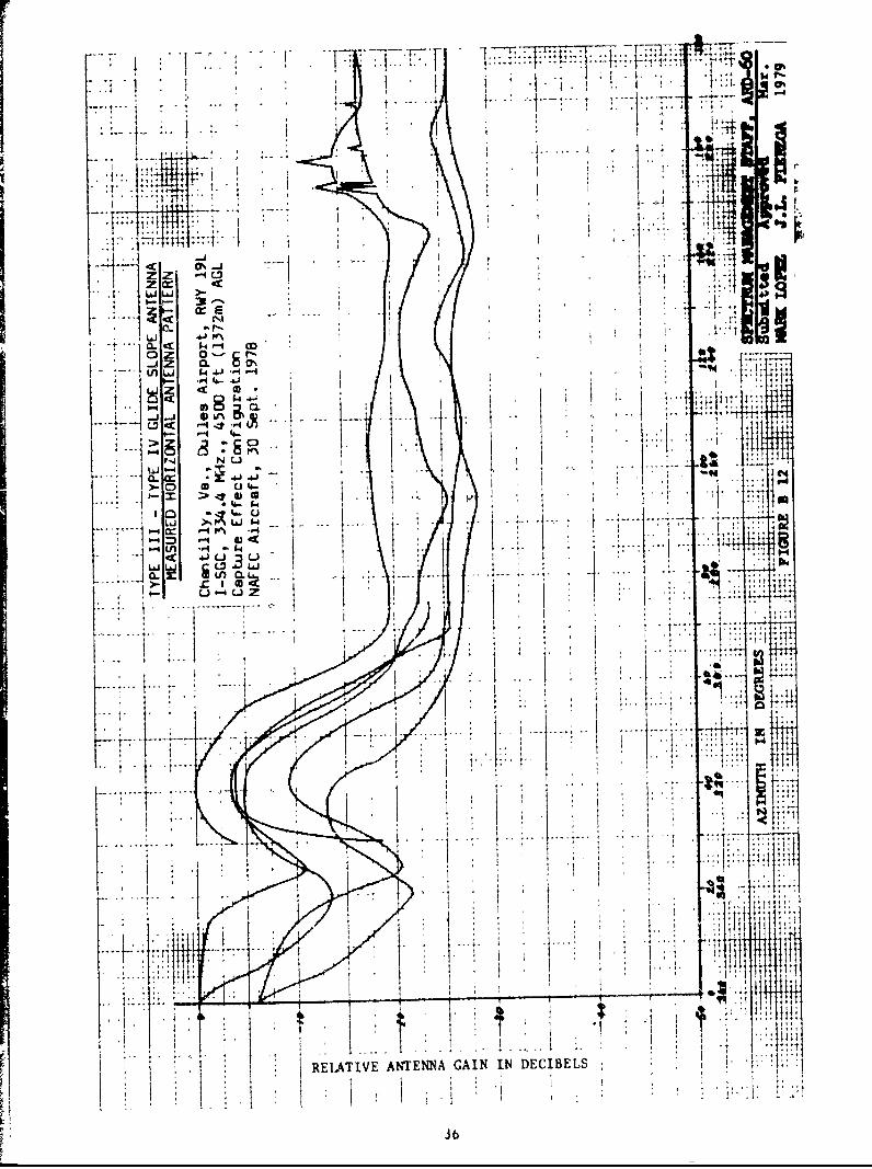
TYPE III AND TYPE IV ANTENNAS
The Type III antenna is composed of three Type I antennas mount,.-d on an
iron frame with an array spacqig of approximately 0.75 wave lengths at the mid-
band frequency (332.0 MHz). The Type IV antenna is similar to the Type III
antenna, except it contains three Type II antennas. (This amounts to the add-
ition of 3 heaters and does not affect the horizontal antenna pattern). These
two types are the most widely used glide slope antennas.
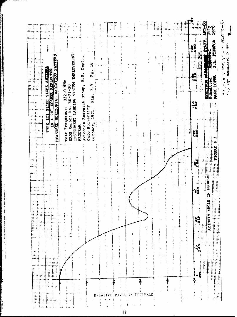
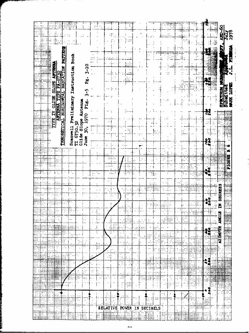
The available data includes nine theoretical and measured patterns taken
fro various publications (Figs. B1 Lhru B8 and Bl). These data compare
reasonably well with the applicable specifications; FAA-E-2245 and FAA-E-2429
(Figs. G2 and GS). An additional five measured patterns were obtained from
NAFEC data (Figs. B9, BIO, B12, B13, and B14). These patterns show some dis-
crepancies. Allentown and Hagerstown compare well with both the theoretical
pattern and the specifications, but don't appear to meet the modified require-
ment of the contract specification with tegard to the lower limit of the antenna
pattern between 0 and 50 degrees. Dulles does not compare well with either
the theoretical pattern or the two specifications. No axplanation for this dis-
agreement is available at this time. Allegheny County compares reasonably well
with the recommended Type III - Type IV trequency assignment pattern, but
contains an unexplained peak between 60 and 8' devgrtes whert, the data exceeds
the -16dB maximum. Reading agrees well with the Type 1II - Type, IV pattern
in the front course, but contains some unusual varifations in the data outside
20 degrees. NAFEC could provide no exp anatioiS tort |hest, tttregularities.
The frequency assignment antenna pattt tn reconmuended tor tiv Type Ill and
23

Type IV glide slope antenn~as is based on specification FAA-E-2245 (Fig. G2)
and the material in Appendix V.
24

-1
41 c**ii
to I
T, .171
252

4 Id
00
10, 1'..1 ... j~ .. I
4* Ck
...........................................................
V lilt,
.... .... .... ... wi NdFIES
0-4A
cn 0 V41.< *
U) 4 ..- rn w
WI IC fn
V* 0 P,W.g-, w. u a p
1*1
~4 1
~ a * a 2 7

.. -.. ....... ,.L
.... ... ... *
tii 4
1. .
.. ,... .... H.
A 0*M C3
- t
.. 7 ,
1'14
RELATIVE POWER IN DECIBELS t I

""~ ~~~~~~wl T -Til " ...'"' ...
V'- I M IT
ig'
-I'.
::' i
t t.=; ... ,,S * !t :... i ! I - i
I._: 1! 1 a . I :. ..1. ] .. ' 1
0 00
tH *,i. .. . . .. t: I
I. i : + : , t • • r. ': t -: It
' ' ' .'t j. . .. i
. ... ..
litl
!ti
E I VEATEN
F "'F. I '1 .....
. ........ i '1 i. !''- -r . .1A.-.I-.-A.-' "," .-.," .b
I 2$
-.-77.T- 7-, 1I----- 4 , :414
S13
001 t 1
40
7_17 :.T .
~~T..
coo: * ~ .Iso
1 4 I
TT~= t-71
- r--. ~~W -.----
It T V
.. ,~~~ - -4A I __ j t Q
:4-L~ .
__ _ I. *F,...
-7r2:
=771--
RELATIVE POWER IN DECIBELS' ~I 9,MV

r7 T
4-
Lr.1
rn 81
Tr%-To~ --
0~
7- 7=17R~1H Ir
Ti

tn 0
eFa-T -- . . .. . + " .. ;
04b 4 4 4
I, "I! " ;: , 41
, ~ * ,+ . .,-,
- I + , , .. + , ,
F- -
N
RE ... IV E -I
F , : .. . .: ... .. . .. . . .,+* 4 + "4, "4
* , 4 i * .. ...
* . 4
.... ... . . 1,, . ,+;.. . . .* . ,
1- + . . .[..... . . I 4+ " i , , ..
3tA

J, 7. R.
t 0
U .t
s-
------- -- --
NJ 4 4
REATV ANT. GANIN.CIB!
* *~ :2~33

E.- -- -.:t - - -- - -....- ---.... .---
-
4- 1i1 71i 1 7 *0'
-. ' . -- . . ...
..... ,-L j........ ...... j.- . I
. 7 ; .-
" : '
4..
i.)
cr in
Ott -- -- -- -- S
w .. + .J I " .. . "
ot
n0 ' .. ...
- 4 i " ! L _ _ .. .
. i!v ' : ": ' :
t"",,- t
- ~ f44
J4I,4i::. I. 77- ..-..... /r I.1 ,..

" " _ " t' t T . T , i.I
r CC . .
I':'- - r "~4iS I-" 'I:
LI L.
.*
' " F ...... i .......... .... i....... .... ....
Ln <- x "
z C 2 : - - .. .
.4J 0.
L 1 4Z .• .
" > 1 - 7* ° ... " J' .
7.-,
Z :I " .~~
: : ! RELATIVE ANTENNA GAIN IN-DECIBELS 1...
3------H --- i
9 -1.i 13b

4.-.
.......................... 4
1j - . 7z z 0-4
Ln L" 6 4 .4 - -
U o -4 - ...
L) u 2
ii, lei (n45u z. ~ '
1 b. ~.d 4 . :31
e~..h.
171, 7. T
RELAIVE NTENA GIN I DECBEL36.

I TZFI ~77
TIM * II 22 Nil,~
JC..3' 4141
.4.
L4tJ .- 4k 64 u
41
,13.
. . . . . ./. ell:~
1 RELATIVE ANTENNA GAIN IN DECIBELS
.17

r+
14 -a-
CL1 <
-j z .-4- f1.
- . . . .-H W. -i- - 0- W
N U
E . ....
PON_ 4!
-i. ----
I- T
1- RELATIVE ANTENNA GAIN IN DECIBELS - I4~;iv
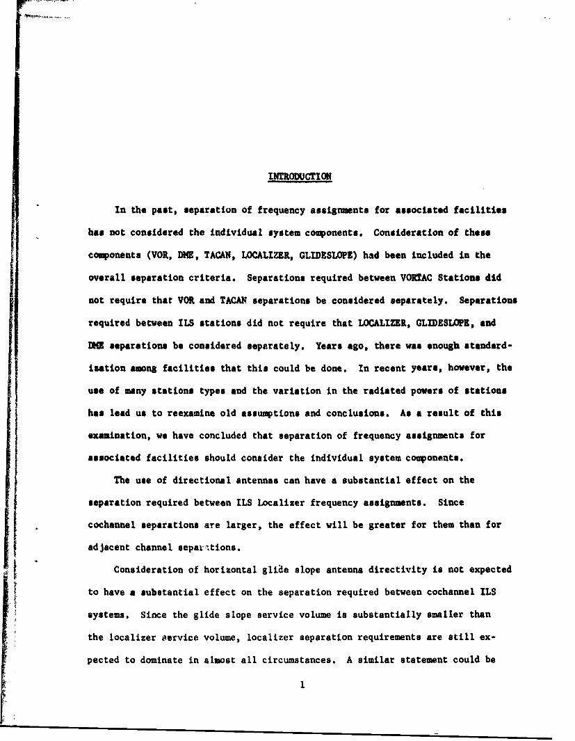
APPENDIX C
THE TWO-LAMBDA CASSEGRANIAN ANTENNA
The two-lambda cassegranian glide slope antenna is produced by Texas
Instruments for use with its AN/GRN-27 (V) and Mark III glide slope systems.
Each antenna consists of a single dipole with a director, reflector, secondary
two-lambda by one-lambda reflecting surface, and two proximity (monitor) probes,
all enclosed in a radome.
Only limited data on this system was available. The three measured pat-
terns supplied by T.I. (Figs. C2 thru C4) agree well with the theoretical pat-
tern (Fig. Cl). In addition, they fall within the limits of FAA specification
FAA-E-2429 (Fig. G5). The two patterns produced from NAFEC data (Figs. C5 and
C6) don't agree very well with the theoretical pattern. In addition, they
appear to have a narrower front course pattern than what is required by the
specification.
The frequency assignment antenna pattern recommended for the two-lambda
cassegranian glide slope antenna is based on specification FAA-E-2429 (Fig.
5) and the figures in Appendix C.
J9

4- 4.4--
";1 1 4 1 , I 1 4-A
. -
"4-
-t_7 777
4- r2-3
t9- c.T
LAJ .- A.j.::I
C111
4
--1 0 Isti0~IIII ,:$ -~ 2 WEN At 14DCBL:-;
2:1L) La.. 1 ::j:JJpj.~ jj4$j' 2
NJ0

........ ..
.. .......... .
i~im
04-- -- cb
-- 0
cr- -- Vm I~.;i~ -I I * I,
4c9 z
< 1
RELATIVE POWER IN DECIBELS I i1I -1. 41

- .j4
t. -fill "
4: A . 4 ~:
j M_
44 .IRELATIVE ANTENNA GAIN IN DECIBELS
42

rd
4KI t
4)
44 1 W
1.43

-4 -. 1 L
.L; A, '4'
17 .f 4
-4-4t
. .. ...... ..
.. ......
I RAIV ATNMGAN NI ~
~~44

.'.,z4 4..
gooll 1
1~~ *1 -
S ~14
* .,
4-6- - o
t REATV ANTNN GANIDCBL
459.f.I.

APPENDIX D
THE STAX-38 ANTENNA
The Stan-38 glide slope is a part of the British ILS system located at
Dulles Airport. This is the only system of its kind presently conmissioned in
the U.S. Additional installations in this country are unlikely.
This system uses an image - type antenna designed for use in the conventional
null reference, sideband reference, and capture effect systems. The antenna
is unique in that each aerial contains six dipoles (U.S. manufactured arrays
house a maximum of three).
Only limited information was available on the Stan-38. The one antenna
pattern obtained (Fig. DI) was taken from the British instruction manual. The
frequency assignment pattern is based a this pattern, the theoretical 3dB
points, the side lobe ratio, and the front-to-back ratio.
46

... .. ....J
+ V1RELTIV POE'd EUI
...... 1
i7

APPENDIX E
THE END-FIRE SLOTTED CABLE ANTENNA
This antenna system is a non-image, end-fire type glide slope currently
under developement. A ground image is not required to form the glide path.
Rather, the difference in path lengths from the two antennas to the aircraft
produces the on-or-off course signals. This system is designed to provide
glide slope service for runways where site conditions make it difficult to in-
stall the existing systems.
The only pattern available (Fig. El) was taken from- the test evaluation
at Rock Springs, Wy. The frequency assignment pattern was chosen using this
data and a conservative estimate of the systems off-course szimuthal pattern.
48

1~ 1 -2FTh
-. T- I,
11 )
'
ti. i .-.t-- r
4-3
0 0... .... j U3 4 '1
V U)
-77 =- 7:=
-"I
-4-~T -+ 7-
tI : :ii T1ixT* 1 4
RELATIVE POWERIN DEC IBELS 1:
LA]..~~i i L L L i I
49
.77
I .
A L J .
Z z -4L" V0-
i. ojz CL
Vmj~ 644 - .U* 4. 4 L
> 0.)
07- m~ -4P 4 1
1-4<6-4
z I~ K m
F1RELATIVE ANTENNA GAIN IN DECIBELS

o-.
.74..
Id-.* I#
'R Fl TIVFIkWIIN F F
ti2
r Kj~ .. , >4q v ...-
0l-i + ) 0
oE-4
... .. ..
LIT:T
. .. ~........ .?
51.

APPENDIX G
FAA SPECIFICATIONS
In our search for glide slope antenna specifications, the following
documents were found to be applicable:
FAA-E-2245. This document was originally published March 11, 1966.
Three amendments, the most recent dating March 24, 1969, have been authorized.
Seven types of antennas are described in this specification.
Type I - This antenna contains a single dipole mounted on
an elliptical ground plane and completely enclosed
in a radome. Its horizontal free space radiation
pattern is shown in Figure G1.
Type II - Type II antennas are the same as Type I, except
they are equipped with a heater system. Its
antenna pattern is the same as the Type I.
Type III- This is an array of three Type I antennas grouped
to provide azimuthal directivity. The curve in
Figure G2 provides the horizontal free space
pattern for the Type III and the Type IV antennas.
Type IV- This antenna is the same as a Type III antenna, except
for the addition of heaters (Type II antenna elements).
Its pattern is the same as the Type III.
Type V - This is an array of two dipoles mounted one quarter-
wavelength from a vertical ground plane. The horizontal
free space radiation patterns given in Figure G3.
53

Type VI - This is a single dipole identical to those comprising
the Type V antenna, but utilizes a smaller ground
plane. The nominal antenna pattern is to be defined
by the contractor at the time that the initial equip-
ment is submitted.
Type VII - This antenna consists of an array of two colinear
dipoles mounted one quarter-wavelength from a parabolic
ground plane. Figure G4 provides the horizontal
free space pattern requirements.
This specification (FAA-E-2245) covers most glide slope antennas in use
today. Type III and Type IV antennas are the most abundant.
FAA-E-2429. This specification, dated January 2, 1970, is used in pur-
chasing new image-type glide slope antenna systems. Both class 1 (null refer-
ence) and class 2 (capture affect) systems are co'.ered. The sideband refer-
ence system is a modified version of the null reference syotem (Section 1.1,
FAA-E-2557, April 2, 1973) and must meet the same horizontal pattern require-
"Ients.
This document does not differenciate between antenna types or element
numbers, but rather sets general antenna array requirements. The antenna
array is defined as "single or muitiple horizontally polarized elements..."
Thus, wheth.2r the antennas are in the null reference, sideband reference, or
capture effect configuration, the same horizontal radiation pattern will be
required by the specification.
The lower limit of this spec ification was modified in the contract
spec it teat ien F-74WA-3364. M,1sured data indicates tlt this requirement iS
Jutticult to me'et, even tot tilte' nAV1.enas built under this COt 'rCt (Figs.
},4

59 and B10).
The end-fire slotted cable and the waveguide glide slope antennas are
still under development. Consequently, there are no current FAA specifications
which apply to these non-image type antenna systems.
55
'.44 "t. +4J-r-7 '1
.. :~ Lt11-'"T I II
4t4~
0 ~ ~U
Ii~
4 WI 4
I ~. ... ...~ . -
.7. 11
REAIE OE IN EIBL
.......... -56

0(3
T. - Tl
M, 7. 10
_ _
0
04 C-4:. V4
..-. -74A
.04 4..,
64 7-..-
b4A~ 4
17
4.- - - .-
.... ....
TrI
;F M
- -4 1 1
R RlA T IV E P MIER IN D EC IBELS ' ti: 'i1 !iI I": " , , I 5t
57

0-
421
.. ... .... .. ..i i 1 +
z o . . - . , , + . . + 'I .
cn I
,q4 ...Plu . . . . . , ,,+ ,
8* z
, '-1 , I ... •. -1 ... . . , . I.
*k 4 -I 1 *t. , t. -i
-"4.
4 .4..1
.. ... ... ... . , , ... ........... .......... .. .
......... - . . ....
, ! , ! < . . . .. ...I ,
1 ~ ' RELATIVE POWER IN DECIBELS i~K
58

-4
-. 4 3- %1f4~ U >
ar 1
CI Ftl
77 7- -7PII Tq4
.... ... .I.. . - - -
* I .1-LA- POWF IN
-4 -1~-TL4 1 59

• , "'! :1" 1 ; I , ,
.. .. . o;w 104
IL i-.- -+, .
K .':. ,-
- N....
z 0-
SN:+ . 1 0 -t I 2 :t ++ic1:
*I : , " + . .t L ." .. . ......
++--
I""-, , .::: b 1jh4+ I _ .. .... . ..+ . .. . ' I.. .... L
1 It
-+ ......... . .. --- + ,. . . . .
f. vI,: , .
60
'.4 71j
04 oI I
+h 1 Iwo-
r.* . L o. .. ...
C 1.. . . . I
1D 70 t " 1'
f I.Ik
4 ff
I;.T77 --- 4
RlLA1'ivt ,. WER 1 N OEC I BF4.

APPENDIX H
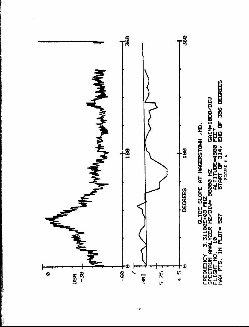
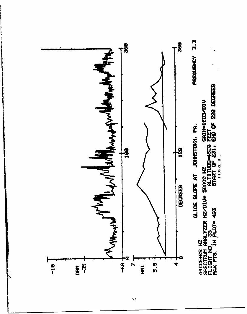
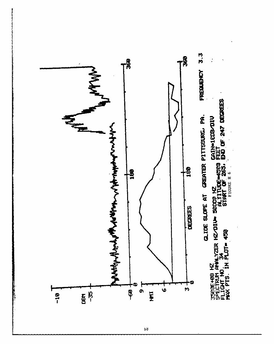
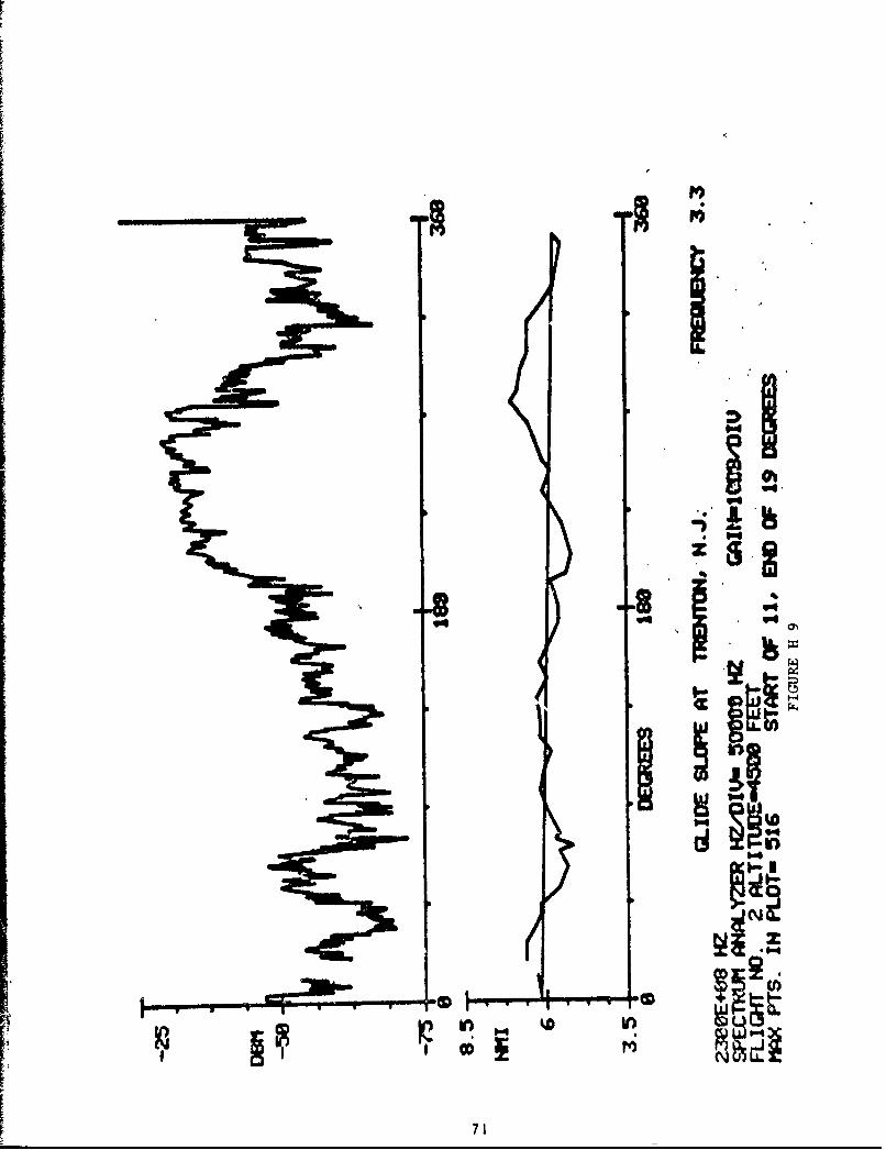
DATA OBTAINED FRHM KAFEC
This section contains copies of the raw data collected by NAFEC. The
following list shows the type of antenna elements are used in each intenna.
LOCATION FIGURE NO. SYSTEM TYPE ELEMENT TYPE
Allentown, Pa. B9 NR III or IV
Allegheny Co., Pa. B14 N7R III or IV
Reading, Pa. B15 NR III or IV
Hagerstown, Md. B1O SBR III or IV
Dulles, Va. B12 CE III or IV
Trenton, N.J, A4 SBR I or II
Atlanti ,' City, N.J. C5 CE Two-Lambda
Gr. Pittsburgh, Pa. C6 CE 'o-Lambda
Data from the Allentown glide slope is the only antenna pattern replotted
in detail. In order to save time, the remaining antenna patterns were replotted
using lines to outline the maximum and minimum limits of the data. Should de-
tailed information be desired on a particular antenna pattern, it is available
in this appendix.
The data taken at Johnstown, Pa. has not been replotted. This glide slope
system was shut down just prior to when the test orbit was flown. The data is
no more than the ambient noise level.

CIIt
I M
LLI) L

co~i
In

C4
ID
r'-La- U -
0I~J1
* ~ iii'
mICA
U-'
qri
tliii
iiE
U i! .
_ T
16

IN6
IL-4
LoI WIOD LL i4

040
'rim-
70
Il
ICD7I.'

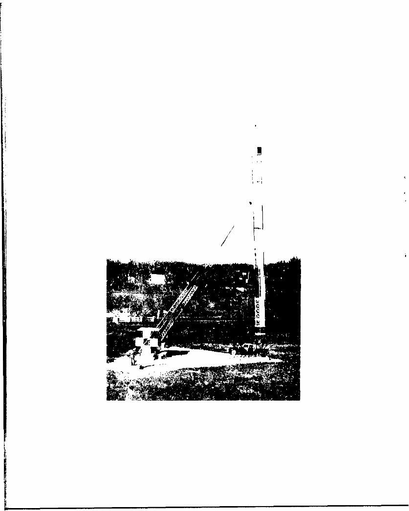
APPENDIX I
PICTURES OF ILS GLIDE SLOPE ANTENNAS
Different types of glide slope antennas have different antenna patterns.
Consideration of these differences may be desirable in the frequency assignment
process. Consideration requires knowledge of the desired and undesired stations'
antenna types. FAA sector offices provide this information to the Electro-
magnetic Compatibility Analysis Center (ECAC). FAA has an interagency agree-
ment with ECAC. The FAA provides to ECAC data on telecommunication systems.
ECAC does the record keeping and provides to FAA computer printouts upon request.
For the frequency assignment process, the Frequency Management Officer (FMO)
may choose to use the ECAC records or he may contact the FAA sector offices
directly. In either case, the identification of the antenna type comes from
the FAA sector maintenance office. Since this is the case, sector personnel
should be capable of identifying the different antenna types. With the many
different glide slope antenna types, this can be a difficult assignment. FAA
type numbers are helpful but they have not been assigned to all antenna types.
In many cases, visual identification is essential. Since, to our knowledge
no single FAA publication shows all glide slope antenna types, this appendix
has been an attewpt to do that.

CAP'U$~ U~~ NLL (F~~N~SIDEBANO teRINCE
,:PUtE~c ULCR~RN.ONF IGU RAT ION COW RfATIONd CONFIUGfRATION
-Ip

-REFLECTOR PICK-UP DEVICE
ASSEMBLYDIPOLE ANT.
CONNECTOR
COAXIAL STUB ASSEMBLYFIGURE I 2
Type I Antenna With Pic k-Up DeviceAntenna Type FA-8090
At'~.Wit" ~~2V~ e

SiDEBAND
ANTENNA
GLIDE SLOP
ANTENNASTYPE FA STSO
CAtRIERt ANTENNA
Null Reference I
SLIDE SLOPEANTE NNA S II I 9 Ji
Antenna Ty~pe FA-8730 In
The Null Reference And
FIGURE 1 4
Capture Effect

Dipole For Antenna Type FA-8730FIGURE I 5
Type TV Antenna Withc,,nt 1reAntenna Type FA-S7,0
FIGURE 1 6

Typne III Antelmu With adome.-,An~tenna Trype V~A-tIO21
FIGURE 7
CARRIERANTE NNA
Il I IAlt oi i I 11W Nul I
C I S i

U U

PICK-UP LOOPS
MOIO DPL
CONNEZIM CONECTOR
FIGURE 1 10Inside View Of The Casing For The
AIL Type 55 Glide Slope Antenna Element
FILLFEDE 1
AIL Type 55 Glide Sloipe Ant'enna Element
79

iI~
V
~ I
A
~3t.aix ~ C; lid~ ~; 1 ~ ~ 1 Qfli~iit In The
F1C;URl' 1 12

w0
0
0
I, I-
I
7 0
'71'.I 0 4.
S
5 t.~fl Si I ~ 1. pe ~ :~Cflt
FIt~RF 1 1 ~
[

04(0
P-4
u

F
/9
74
I
/'77
d P
'I
III t t "
V h*~t1 ~ ~ I
'4
I

I
I II
I
-~ ~\4'~tIIJt \'i~e'n~i
Fl ti-U 1
'a,
r
// if!I t
I

I
1. 1

nENGLISH/METRIC CONVERSION FACTORS
Prcm a km in ft a1t.
an 1 0.01 l10O- 0.393' 0.0323 0.21x10,6 S.33x 10-6a 100 1 0.001 33.37 3.241 0.0006 0.0005ka 100,000 1000 1 33$70 3251 0.6214 035395
in 2.5.40 0.02S4 I.S4xa10' 1 0.0633 1.55X10⁻³ 1.37,10-5
ft 30.48 0.30MI 3.0SXl0,4 12 1 1.e910o- I.GWxO"'
at 160.3ON 1*09 1.609 63S60 $250 1 0.651
wa 18S.200 1552 1.552 72330 6076 3.151 I
Pvamo cm2
82 Wm in) ft, 012 mi
Ca I Q.Qvl 1 110ia1 0.ISSO a) 0011 3 ?eW10 11 S 11K101
as 10,000 1 1110-6 1550 10 76 3,66,10- S. halO-
kal 11l10
1110 6 1 55SS310 I 0SXl0' 0.3561 0.2914
ins 6.4S2 0.0000 6.4SaIO.10
1 010009 2 49xl1-0 1.8111lO 0
t2
929.0 0.0929 9.29x10 144 1 3 s9X10. 2.71X10-
ail J.59a1010
Z.Sgx1Ol 2.190 4.01KI0' , '9110, 1 0.7$44
mil 3SAWO~ 1.43,106 3,432' S.31X10, j .10110' 1.3.15 1LI
Prm Cal liter a) in) ft yd) (1. 01 fl. Pt. fl qt. g
Ct
10.001 1Xa106 0.0010 3.S3zl0-, 1.31xl3)- 0.0335 0,0021 0.0010 0.0002
liter 1000 1 0.001 63.021 0.0353 0.0013 33.81 .3313 1.057 0.2642
63 1xi0, W000 1 61.009 3S 31 1308 33,500 2113 1057 2*4.2
in3 16.39 0.0163 1,641101' 1 0 000^ 14a110-, 0,5$43 0 0346 2313 0.0043
tts 25,300 25 32 0.0253 11'215 0 0310 95' S59.54 0.0113 7.481
Y41 765.000 764 5 0.7646 467)0 2'1 1 .1900 16.6 507 9 202.0
(1,. 01. 29.37 0.2957 2,9600-5 1 505 0.0010 S 5'101 1 0.06.15 0.0312 0.0075
f1. pt.. 473.2 0.473.1 0.0005 258.9 0 016' 0 00t) 36 0.5000 0.1250
f1. qt. 945.4 0.9463 0000W9 S. '3 0 0114 (0 0032 5. 2 1 0.2500
1161. 375S 3.18S 0.0038 231 0 o 31' 0,000 so .1: 8 4
Fro I I o
ks 1000 1 Is 2' 2 0S 0.0031 A&~. o.." ,
01 51 35 o 0.81 1 0 06.15 3. IXO'lb 4S3.0 0 4 S3c l 1 0. 0005
tan 40', 0 '2 3." 000 200.
tVERATUR
F L'F q/9( 32


