
The principles of CCTV design in VideoCAD 1
© 2003-2016 CCTVCAD Software http://cctvcad.com
The principles of CCTV design in VideoCAD
Part VI Lens distortion in CCTV design
Edition for VideoCAD 8 Professional S. Utochkin
In the first article of this cycle we represented the camera view area in the form of a regular
pyramid (Fig 1).
Fig. 1. Camera view area without lens distortion.
This simplification is acceptable, if requirements for precision are not high.
However, the actual shape of the view area can differ from a regular pyramid because of influence
of lens distortion.
In addition to the view area shape, the lens distortion distorts distribution of spatial resolution (pixel
density), considered in the second article in this cycle, and shape of objects on the image from the
camera.
In this article, we will examine effects of the distortion and will consider a practical example of
accurate simulation of a camera with short-focus lens.
Contents
Lens distortion in photography and CCTV .................................................................................................................... 2 Distortion in parameters of a short-focus (wide angle) lens........................................................................................... 2 Physical nature of lens distortion ................................................................................................................................... 3 Barrel distortion ............................................................................................................................................................. 3 Pincushion distortion ..................................................................................................................................................... 5 Consideration of lens distortion in CCTV design .......................................................................................................... 7
Modeling a camera with short-focus lens ....................................................................................................................... 8 Camera parameters in specification ............................................................................................................................... 8 Specifying camera parameters in VideoCAD ................................................................................................................ 9 Modeling view area projection in the Graphics window ............................................................................................. 11 Modeling distribution of the spatial resolution (pixel density) .................................................................................... 11 Modeling image from the camera with lens distortion................................................................................................. 13 Modeling 3D view area in the 3D World window ....................................................................................................... 14
Conclusion ....................................................................................................................................................................... 14

2 Part VI Lens distortion in CCTV design
© 2003-2016 CCTVCAD Software http://cctvcad.com
Lens distortion in photography and CCTV
Influence of lens distortion on image is well known in photography. Because of the lens distortion
straight lines on the scene are transformed into curves on the image and rectangular objects become
similar to barrels or pillows. (Fig.2, Fig.3).
Fig 2. Lens distortion is absent. Fig 3. Barrel distortion is visible
In most cases, the image distortion do not lead to a significant loss of its information, at the same
time accounting the distortion is quite complicated. Therefore, in designing CCTV systems influence
of lens distortion is usually neglected.
However, under the influence of the lens distortion not only the image itself is distorted, but the
angles of view, the shape of the field of view of and distribution of spatial resolution (pixel density).
These parameters are not important in the photography, so the impact on them of lens distortion is
not usually mentioned. However, these parameters are highly important in CCTV design.
Under the influence of the lens distortion, field of view ceases to be rectangular, and actual viewing
angles horizontally, vertically and diagonally may differ significantly from the angles calculated
based on the size of image sensor and the lens focal length.
Distortion in parameters of a short-focus (wide angle) lens
For example, let's consider the specification of a typical short focus lens T2314FICS-3 (Computar):
Fig. 4. Specification of a typical short focus lens.

The principles of CCTV design in VideoCAD 3
© 2003-2016 CCTVCAD Software http://cctvcad.com
With lens focal length of 2.3 mm and the size of the image sensor 1/3" real horizontal view angle
is 113.3 deg., and the vertical view angle is 86.3 deg. But calculation gives lower values - 92.4
deg. and 76.1 deg.
The form of the camera view area with this lens differs from the standard pyramid (Fig.10) and
therefore cannot be accurately calculated by lens calculators or modeled by simple CCTV design
software. The cause of warping the view area is the Lens distortion.
Physical nature of lens distortion
The optical magnification of a lens is the ratio of the size of image of an object projected by the
lens on the image sensor to the real size of this object.
If the optical magnification is constant within the field of view, we obtain the projection of real
objects without distortion of their form.
The lens distortion arises from the fact that the optical magnification of a real lens is not constant
over the entire field of view. Optical magnification varies depending on the distance from the
center to the edges of the field of view.
Depending on whether the optical magnification of a lens is decreased or increased with distance
from the center of the field of view, the barrel distortion or the pincushion distortion is
distinguished.
Traditionally from photography, the titles barrel and pincushion are associated with the distortion
of cross-hatch on the image. But the shape of the field of view varies oppositely the title. Thus,
with the barrel distortion the image resembles a barrel (Fig.6), and the shape of the field of view
resembles a pillow (Fig.8),. With the pincushion distortion, the image resembles a pillow (Fig.16),
and the shape of the field of view - a barrel (Fig.18).
The lens distortion should not be confused with the perspective distortion (Fig.11), which is
normal on all images obtained with wide-angle lenses. Perspective distortion does not change
pyramidal shape of the view area, rectangular shape of field of view and distribution of the spatial
resolution.
Barrel distortion
When by moving away from the center of the field of view the optical magnification decreases,
then objects at the edges of the field of view seem compressed, and the spatial resolution
decreases from the center to the edges, and the field of view is stretched to the edges. Real angles
of view in this case are more than the calculated angles (Fig.7,8). This is called the barrel
distortion. The barrel distortion is most common and usual for wide angle lenses.
In particular, the lens considered above has just the barrel distortion. Let's consider VideoCAD
model of image from this lens, the model of field of view, view area projections built with and
without simulating distortion. Position of the camera in both cases is constant (Fig.5..15). The left
figures show models built without distortion, and the right figures - model taking into account the
lens distortion.
Pay attention on the warping of distribution of the spatial resolution (Fig.8). Barrel distortion
increases the field of view, but reduces the spatial resolution, the farther from the center of the
field of view, the stronger.
Objects distant from the center of the field of view will be displayed with lower resolution than
the objects at the center of the field of view. Since the lens calculators consider spatial resolution
only at the center, the actual spatial resolution over most of the field of view will be worse than
estimated one.
4 Part VI Lens distortion in CCTV design
© 2003-2016 CCTVCAD Software http://cctvcad.com
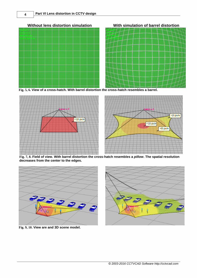
Without lens distortion simulation With simulation of barrel distortion
Fig. 5, 6. View of a cross-hatch. With barrel distortion the cross-hatch resembles a barrel.
Fig. 7, 8. Field of view. With barrel distortion the cross-hatch resembles a pillow. The spatial resolution decreases from the center to the edges.
Fig. 9, 10. View are and 3D scene model.

The principles of CCTV design in VideoCAD 5
© 2003-2016 CCTVCAD Software http://cctvcad.com
Without lens distortion simulation With simulation of barrel distortion
Fig. 11, 12. Camera image model. The slope of the men in the upper corners (Fig. 11) is caused not by the lens distortion but by the perspective distortion, which is natural for any wide-angle lens.
Fig. 13, 14. 2D View area projection.
Pincushion distortion
When by moving away from the center of the field of view the optical magnification increases,
then objects at the edges of the field of view seem stretched, and the spatial resolution increases
from the center to the edges, and the field of view is compressed to the edges. Real view angles in
this case are less than the calculated angles (Fig.17, 18). This is called the pincushion distortion.
The pincushion distortion occurs seldom with teleobjective lenses.
Let's consider models built with and without simulating distortion. The models are given to
illustrate the pincushion distortion, they are not associated with a certain model of lens. Position of
the camera in both cases is constant (Fig.15..24).
Note the warping of distribution of the spatial resolution (Fig.18). Pincushion distortion decreases
the field of view, but increases the spatial resolution, the farther from the center of the field of
view, the stronger.

6 Part VI Lens distortion in CCTV design
© 2003-2016 CCTVCAD Software http://cctvcad.com
Without lens distortion simulation With simulation of pincushion distortion
Fig. 15, 16. View of a cross-hatch. With Pincushion distortion the cross-hatch resembles a pillow.
Fig. 17, 18. Field of view. With Pincushion distortion the cross-hatch resembles a barrel. The spatial resolution increases from the center to the edges.
Fig. 19, 20. View are and 3D scene model.

The principles of CCTV design in VideoCAD 7
© 2003-2016 CCTVCAD Software http://cctvcad.com
Without lens distortion simulation With simulation of pincushion distortion
Fig. 21, 22. Camera image model. As the lens is teleobjective (narrow angles), the perspective distortion is not unnoticeable (compare with Fig. 11).
Fig. 23, 24. 2D view area projection.
Consideration of lens distortion in CCTV design
In practice, the effect of distortion is actual for lenses with focal length of less than 4mm. For long-
focus lenses the distortion is usually small and can be neglected.
The most common barrel distortion of short-focus lenses causes the actual camera field of view is
wider than the calculated one, with stretched corners, and the actual spatial resolution equals to
calculated one only at the center of the field of view. The rest of the field of view will have the
spatial resolution worse than estimated. Moreover, at the corners of the field of view the spatial
resolution may be worse in several times (Fig.8).
In cases required accuracy, compare the actual angles of view from the camera manufacturer's
specifications or received by practical measurements with the calculated angles of view obtained
from a lens calculator based on the lens focal length and the size of the image sensor. If the angles
are significantly different, the distortion of the lens of the camera can be noticeable. (See example
of the lens above).
Simulation of lens distortion is realized for the first time in the eighth version of VideoCAD.
8 Part VI Lens distortion in CCTV design
© 2003-2016 CCTVCAD Software http://cctvcad.com
Since the parameter "distortion" is missing in specifications of cameras and CCTV lenses, the lens
distortion in VideoCAD is defined by a combination of calculated view angle and real view angle.
The calculated view angles are calculated in the program from the lens focal length and format or
the actual size of the image sensor.
The real angles are usually given in the specifications of cameras and lenses. If the angles are
unknown, it is possible to get them by practical measuring.
To determine the lens distortion it is enough to set one of three real angles: horizontal, vertical or
diagonal. It is preferable to set the horizontal angle. Missed real angles will be calculated by
VideoCAD. For maximum accuracy, you can specify 2 or all 3 real angles.
From the specified angles VideoCAD calculates distortion, which will be taken into account when
constructing models of view areas, distribution of spatial resolution and images from cameras.
Modeling a camera with short-focus lens
Camera parameters in specification
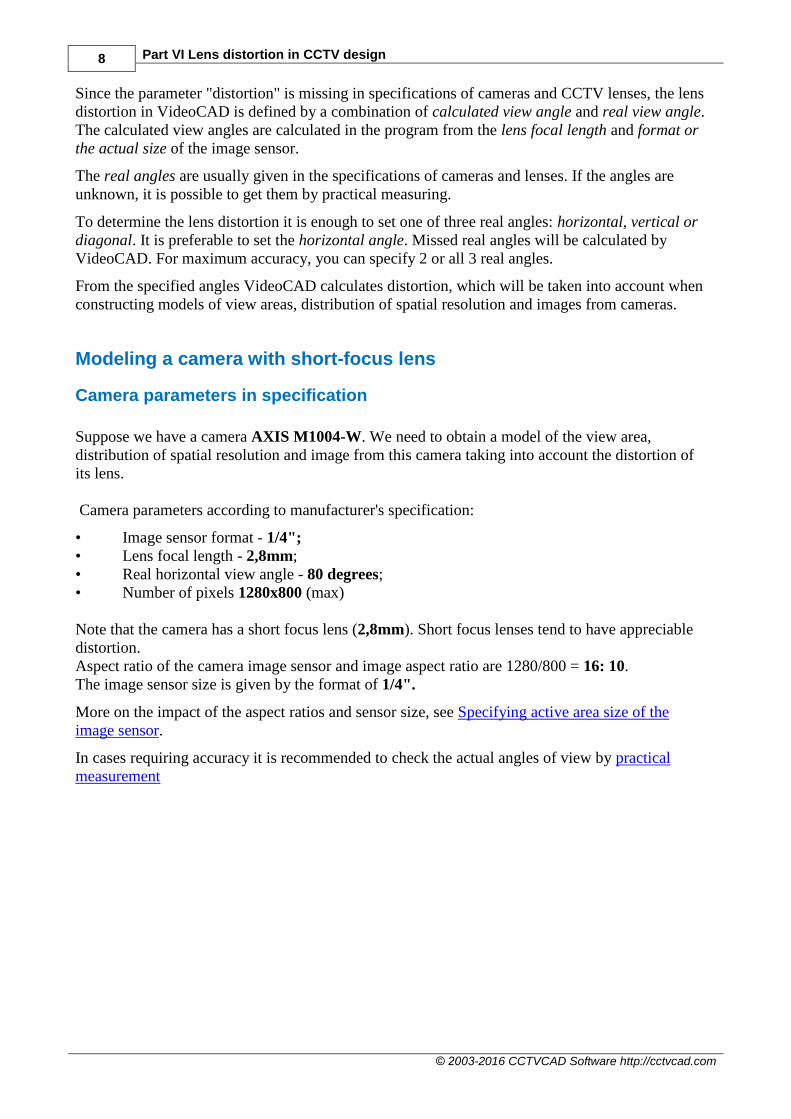
Suppose we have a camera AXIS M1004-W. We need to obtain a model of the view area,
distribution of spatial resolution and image from this camera taking into account the distortion of
its lens.
Camera parameters according to manufacturer's specification:
• Image sensor format - 1/4";
• Lens focal length - 2,8mm;
• Real horizontal view angle - 80 degrees;
• Number of pixels 1280x800 (max)
Note that the camera has a short focus lens (2,8mm). Short focus lenses tend to have appreciable
distortion.
Aspect ratio of the camera image sensor and image aspect ratio are 1280/800 = 16: 10.
The image sensor size is given by the format of 1/4".
More on the impact of the aspect ratios and sensor size, see Specifying active area size of the
image sensor.
In cases requiring accuracy it is recommended to check the actual angles of view by practical
measurement

The principles of CCTV design in VideoCAD 9
© 2003-2016 CCTVCAD Software http://cctvcad.com
Specifying camera parameters in VideoCAD
Create new camera by clicking the New camera button on the toolbar of the Graphics
window and place it on the layout.
Open the Camera geometry box and specify
camera parameters:
Sensor format - 1/4" 16:10;
Lens focal length - 2,8mm;
Aspect ratio: 16:10 (1280/800=16/10).
Click on the + button to open
the Sensor and lens box.
Fig. 25. Camera geometry box.

10 Part VI Lens distortion in CCTV design
© 2003-2016 CCTVCAD Software http://cctvcad.com
In the Sensor and lens box, pay attention to the
difference between the calculated horizontal
view angle - 68.6 degrees and the actual view
angle from the manufacturer's specification - 80
degrees. The difference indicates that the lens
distortion is present.
On the Lens distortion panel check the Horiz.
checkbox and enter 80 to the box under it.
Clear the Vert. and Diag. checkboxes, because of
the vertical and horizontal actual view angles are
unknown.
Fig. 26. Sensor and lens box.
The principles of CCTV design in VideoCAD 11
© 2003-2016 CCTVCAD Software http://cctvcad.com
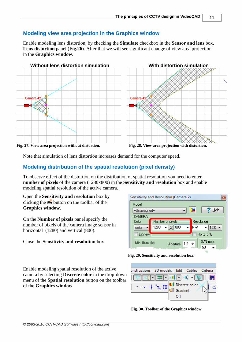
Modeling view area projection in the Graphics window
Enable modeling lens distortion, by checking the Simulate checkbox in the Sensor and lens box,
Lens distortion panel (Fig.26). After that we will see significant change of view area projection
in the Graphics window.
Without lens distortion simulation With distortion simulation
Fig. 27. View area projection without distortion.
Fig. 28. View area projection with distortion.
Note that simulation of lens distortion increases demand for the computer speed.
Modeling distribution of the spatial resolution (pixel density)
To observe effect of the distortion on the distribution of spatial resolution you need to enter
number of pixels of the camera (1280x800) in the Sensitivity and resolution box and enable
modeling spatial resolution of the active camera.
Open the Sensitivity and resolution box by
clicking the button on the toolbar of the
Graphics window.
On the Number of pixels panel specify the
number of pixels of the camera image sensor in
horizontal (1280) and vertical (800).
Close the Sensitivity and resolution box.
Fig. 29. Sensitivity and resolution box.
Enable modeling spatial resolution of the active
camera by selecting Discrete color in the drop-down
menu of the Spatial resolution button on the toolbar
of the Graphics window.
Fig. 30. Toolbar of the Graphics window
12 Part VI Lens distortion in CCTV design
© 2003-2016 CCTVCAD Software http://cctvcad.com
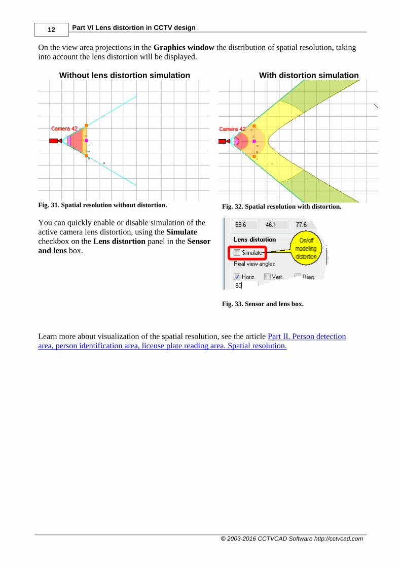
On the view area projections in the Graphics window the distribution of spatial resolution, taking
into account the lens distortion will be displayed.
Without lens distortion simulation With distortion simulation
Fig. 31. Spatial resolution without distortion.
Fig. 32. Spatial resolution with distortion.
You can quickly enable or disable simulation of the
active camera lens distortion, using the Simulate
checkbox on the Lens distortion panel in the Sensor
and lens box.
Fig. 33. Sensor and lens box.
Learn more about visualization of the spatial resolution, see the article Part II. Person detection
area, person identification area, license plate reading area. Spatial resolution.

The principles of CCTV design in VideoCAD 13
© 2003-2016 CCTVCAD Software http://cctvcad.com
Modeling image from the camera with lens distortion
To observe influence of the lens distortion on the image from the camera, open the 3D Video
window by clicking the 3D Video button on the toolbar and place several 3D models within
camera's view area. Choose 3D models from the drop-down menu of the 3D Model button on
the toolbar of the Graphics window.
Without lens distortion simulation With distortion simulation
Fig. 34. Image from the camera without distortion.
Fig. 35. Image from the camera with distortion.
We observe curvature of straight lines on the image in the 3D Video window.
In the 3D Video window the image with distortion is modeled with reduced resolution. You can get
the image with distortion and actual resolution by two ways:
Mark the menu item Real frame size in the main menu of the 3D Video and save the image
with distortion to a file by selecting Image> Save As from the main menu of the 3D Video
window. The saved file will have full size, actual resolution and distortion
Activate PiP tool. In the distortion simulation, the particular view of PIP will have real
resolution.
See details of PiP and main menu of the 3D Video window in the Help system.
14 Part VI Lens distortion in CCTV design
© 2003-2016 CCTVCAD Software http://cctvcad.com
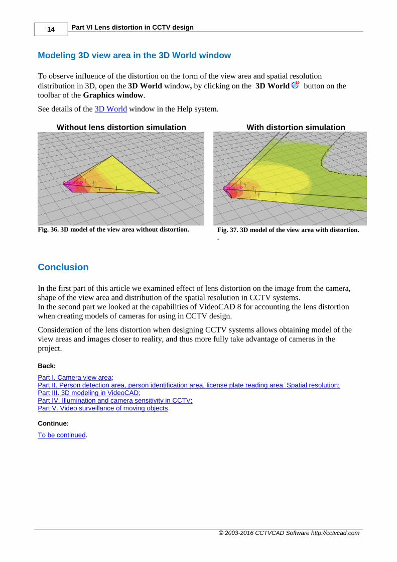
Modeling 3D view area in the 3D World window
To observe influence of the distortion on the form of the view area and spatial resolution
distribution in 3D, open the 3D World window, by clicking on the 3D World button on the
toolbar of the Graphics window.
See details of the 3D World window in the Help system.
Without lens distortion simulation With distortion simulation
Fig. 36. 3D model of the view area without distortion.
Fig. 37. 3D model of the view area with distortion.
.
Conclusion
In the first part of this article we examined effect of lens distortion on the image from the camera,
shape of the view area and distribution of the spatial resolution in CCTV systems.
In the second part we looked at the capabilities of VideoCAD 8 for accounting the lens distortion
when creating models of cameras for using in CCTV design.
Consideration of the lens distortion when designing CCTV systems allows obtaining model of the
view areas and images closer to reality, and thus more fully take advantage of cameras in the
project.
Back:
Part I. Camera view area; Part II. Person detection area, person identification area, license plate reading area. Spatial resolution; Part III. 3D modeling in VideoCAD; Part IV. Illumination and camera sensitivity in CCTV; Part V. Video surveillance of moving objects. Continue:
To be continued.


