
Technical Information TI 005-105October 2016
Canadian Standards Association (CSA)Certified Intrinsically Safe Apparatus,Associated Apparatus, andEquipment with Nonincendive Field Wiring Connections

TI 005-105 – October 2016
2

Contents
Figures ........................................................................................................................................... 5
Tables ............................................................................................................................................ 6
General .......................................................................................................................................7
CSA Marking Code.....................................................................................................................7
Intrinsically Safe Apparatus .........................................................................................................7
Associated Safe-Location Apparatus.............................................................................................7
CSA Approvals ............................................................................................................................7
SPEC 200 System .......................................................................................................................8
UIO and MICROSPEC Subsystems .........................................................................................10
UFM Subsystem .......................................................................................................................14
Field Input/Output (FIO) System.............................................................................................16
CSA Certified Zener Barriers ....................................................................................................22
Nonincendive Circuit Field Wiring Considerations...................................................................25I/A Series System Mass Flowmeter Wiring for Division 2 Locations .....................................28I/A Series System FBMs with CSA Certified I/O Circuits ....................................................28
3

TI 005-105 – October 2016 Contents
4

5
Figures
1 SPEC 200 System - Loop Diagram (Reference Table 1).........................................................92 SPEC 200 System - Loop Diagram (Reference Table 2).......................................................103 UIO and MICROSPEC Subsystems - Loop Diagram (Reference Table 3) ..........................124 UIO and MICROSPEC Subsystems - Loop Diagram (Reference Table 4) ..........................135 I/A Series System HART Loop Diagram with UIO/UCM ..................................................146 UFM Subsystem - Loop Diagram (Reference Table 5).........................................................157 FIO System - Loop Diagram; RTD, Thermocouple, or Nonpowered Contact Inputs
(Reference Table 6)........................................................................................................178 FIO System - Loop Diagram; Intrinsically Safe Apparatus Inputs (Reference Table 6).........189 Typical Loop Diagram for Foxboro 3F8–D2ZA Connected to Telektron Intrinsically Safe
Apparatus (Reference Table 7) .......................................................................................1910 TankExpert Hydrostatic Gauging and Inventory Management System (Division 1) – Loop
Diagram (Reference Table 8) .........................................................................................2011 TankExpert Hydrostatic Gauging and Inventory Management System (Division 2) –Loop
Diagram (Reference Table 8) .........................................................................................2112 Loop Diagram Showing 860, 82 ooo–D, RTT10 or RTT20 Transmitter, Model HHT, and
CSA-Certified Zener Barriers ........................................................................................2413 Loop Diagram Showing 860, 82ooo–D, RTT10 or RTT20 Transmitter, Model HHT,
RDM10 Remote Digital Meters, and CSA-Certified Zener Barrier ...............................2414 E83 and 83 Series Vortex Flowmeter - Loop Diagram (Reference Table 9) ..........................2515 IMT20 Series Transmitter - Loop Diagram (Reference Table 10).........................................2716 CNN Loop Diagram..........................................................................................................28

6
Tables
1 SPEC 200 System Connected to Foxboro Intrinsically Safe Apparatus (see Figure 1) ............82 SPEC 200 System Connected to Foxboro Intrinsically Safe Apparatus (See Figure 2)............93 UIO and MICROSPEC Subsystems Connected to Foxboro Intrinsically Safe Apparatus
(See Figure ) ..................................................................................................................114 UIO and MICROSPEC Subsystems Connected to Foxboro Intrinsically Safe Apparatus (See
Figure ) .........................................................................................................................135 UFM Subsystem Connected to Foxboro Intrinsically Safe Apparatus (See Figure 6)............156 Field Input/Output (FIO) System Connected to Foxboro Intrinsically Safe Apparatus (See
Figure 7 and Figure ) .....................................................................................................167 Foxboro Associated Apparatus Connected to Other Manufacturer's Intrinsically Safe
Apparatus (See Figure 9) ...............................................................................................198 TankExpert Hydrostatic Gauging and Inventory Management System (See Figure 10 and
Figure 11) .....................................................................................................................199 Foxboro Intrinsically Safe Apparatus Connected to CSA Certified Zener Barriers (Other
Manufacturer's Associated Apparatus) ...........................................................................2210 Apparatus Connected with Nonincendive Field Wiring ......................................................2511 FBMs with CSA Certified I/O Circuits...............................................................................28

TI 005-105 – October 2016
GeneralThis document provides the user with information necessary for the connection of Canadian Standards Association (CSA) approved intrinsically safe apparatus and associated apparatus. Wiring procedures for Foxboro intrinsically safe systems are provided in Foxboro Instructions (MIs) applicable to the systems in question.
CSA Marking CodeThe marking codes adopted by CSA for intrinsic safety are:
Exia — means the apparatus is intrinsically safe.
[Exia] — means the associated apparatus provides intrinsically safe circuits.
Intrinsically Safe ApparatusThe term “intrinsically safe” means that any spark or thermal effect that may occur in normal use, or under any conditions of fault likely to occur in practice, is incapable of causing an ignition of the prescribed flammable gas, vapor, or dust. Intrinsically safe apparatus is apparatus that may be installed in a hazardous location, in which all the circuits are intrinsically safe, or that is designed to form part of an intrinsically safe system.
Associated Safe-Location ApparatusAssociated safe-location apparatus is apparatus designed to form part of an intrinsically safe system, in which not all the circuits are intrinsically safe, but which affects the safety of the intrinsically safe system of which it forms a part. Such equipment may not be installed in a hazardous location unless provided with appropriate protection.
CSA ApprovalsTable 1 and Table 2 list the SPEC 200 System CSA associated apparatus connected to Foxboro intrinsically safe apparatus.
Table 3 and Table 4 list UIO and MICROSPEC Subsystems associated apparatus connected to Foxboro intrinsically safe apparatus.
Table 5 lists UFM Subsystem associated apparatus connected to Foxboro intrinsically safe apparatus.
Table 6 lists FIO System associated apparatus connected to Foxboro intrinsically safe apparatus, and Table 7 lists Foxboro associated apparatus connected to other manufacturer's intrinsically safe apparatus.
Table 8 lists TankExpert Hydrostatic Gauging and Inventory Management System associated apparatus connected to Foxboro intrinsically safe apparatus.
Table 9 lists Foxboro intrinsically safe apparatus connected to CSA-certified zener barriers (other manufacturer's associated apparatus).
Table 10 lists Foxboro apparatus connected with nonincendive field wiring.
7

TI 005-105 – October 2016
SPEC 200 SystemTable 1 and Table 2 list SPEC 200 System input/output cards that are approved by CSA as providing intrinsically safe circuits to the field devices mounted in Class I, Groups A, B, C, and D, Divisions 1 and 2 hazardous locations. The cards must be mounted in a 2ANU–D nest and receive power via a 2AX+DP10–CGB power distribution module (green). The input/ output (I/O) cards must be the –CGB version and operate in one of the approved loops listed in Table 1 and Table 2. Certification is contingent on rack assemblies being wired at specified Foxboro plants.
Table 1. SPEC 200 System Connected to Foxboro Intrinsically Safe Apparatus (see Figure 1)
Associated ApparatusSPEC 200 System
Model NumberField Wiring
Connection Criteria
Intrinsically Safe Apparatus Located in Class I, Groups A, B, C, and D, Divisions 1 and 2
Hazardous (Classified) Locations
2AI–C2L–CGB Input Circuit may connect to: Nonpowered contacts or switches2AI–F2F–CGB2AI–F2V–CGB
Input Circuit may connect to: E83 Series Vortex Flowmeters83 Series Vortex Flowmeters (a) (b)
a. To maintain intrinsic safety in 83 Series Vortex Flowmeters, current loop and pulse output field wiring pairs must be run in separate cables or with separate shields connected to intrinsically safe ground.
b. This Model also intrinsically safe for Class II, Groups E, F, and G, Division 1; Class III, Division 1.
2AI–I2V–CGB2AI–I3V–CGB2AS–I2I–CGB (Channel A)2AS–I3I–CGB (Channel A)
Input Circuit may connect to: Foxboro/ICT 27 Series Pressure Transmitters65 Series Indicators (c)130 Series DMU Transmitter820 Series Transmitters834DP Series Transmitters841, 843, and 847 Series Transmitters892 Series Converter1125 Pressure Transducers1150 Pressure TransducersE83 Series Vortex Flowmeters83 Series Vortex Flowmeters (a) (b)I/A Series Pressure Transmitter (d)870 Series Transmitters (e)870IT Series Electrochemical Transmitters (e)
c. 65 Series Indicator (65FS–CBJB, 65PH–JT, 65PV–JG, 65PV–JT or 65PV-JY) may be connected in a loop with other intrinsically safe apparatus listed in the same segment of the table.
d. Communication -I and -D only.e. 870 Series Transmitters entity parameters based upon connection to 871 Series sensors. Maximum cable length
of CSA certified 871EC or 871FT, 100 ft; 871PH, 500 ft.
2AI–I2V–CGB2AS–I2I–CGB
Input Circuit may connect to:(when associated apparatus is modified per SI 8-00590 only)
65 Series Indicators (c)
2AO–V2I–CGB2AO–VAI–CGB
Output Circuit may connect to: (when associated apparatus is modified per SI 8-00590 only)
2AI–N2V–CGB2AI–P2V–CGB
Input Circuit may connect to: Nonincendive ResistancesResistance Temperature Detectors (RTDs)
2AI–T2V–CGB Input Circuit may connect to: Thermocouples2AI–W3V–CGB Input Circuit may connect to: 65 Series Indicators (c)
820 Series Transmitters2AO–V2I–CGB2AO–V3I–CGB2AO–V5I–CGB2AO–VAI–CGB2AS–I2I–CGB (Channel B)2AS–I3I–CGB (Channel B)2AT–SBU–CGB
Output Circuit may connect to: 65 Series Indicators (c)E69 Series Converters and Positioners
2AT–SBM–CGB Used with 205S–SBU–CGB2AO–L2C–ISR–CGB May be used to switch any approved intrinsically safe loop
8

TI 005-105 – October 2016
Figure 1. SPEC 200 System - Loop Diagram (Reference Table 1)
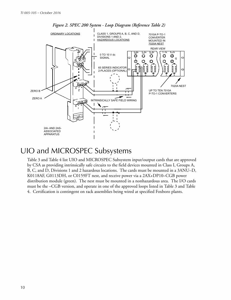
Table 2. SPEC 200 System Connected to Foxboro Intrinsically Safe Apparatus (See Figure 2)
Associated ApparatusSPEC 200 System
Model NumberField Wiring
Connection Criteria
Intrinsically Safe Apparatus Located in Class I, Groups A, B, C, and D, Divisions 1 and 2
Hazardous (Classified) Locations
2AI–I2V–CGB2AI–I3V–CGB2AS–I2I–CGB(Channel A)2AS–I3I–CGB(Channel A)
Input Circuit may connect to: 65 Series Indicators (a)7010A Pneumatic-to-Current Converter
a. 65 Series Indicator (65FS–CBJB, 65PH–JT, 65PV–JG, 65PV–JT, or 65PV-JY) may be connected in a loop with other intrinsically safe apparatus listed in the same segment of the table.
ORDINARY LOCATION CLASS 1, GROUPS A, B, C, AND D,DIVISIONS 1 AND 2,HAZARDOUS LOCATIONS
65 SERIES INDICATOR2-PLACES (OPTIONAL)
INTRINSICALLY SAFE APPARATUS(SEE TABLE 1)
ZERO B
ZERO A
2AI-, 2AO-, 2AS-, AND 2AT-ASSOCIATED APPARATUS
INTRINSICALLY SAFE FIELD WIRING
+
–
+–
FIELDDEVICES
FIELDDEVICES
0 TO 10 V dcSIGNAL
9
TI 005-105 – October 2016
Figure 2. SPEC 200 System - Loop Diagram (Reference Table 2)
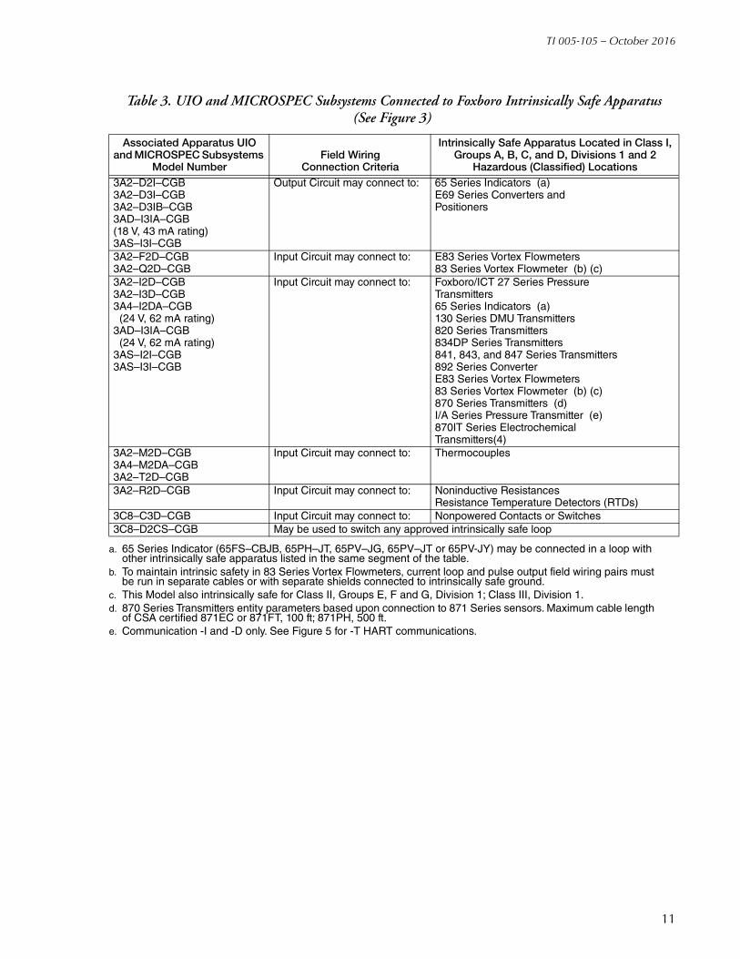
UIO and MICROSPEC SubsystemsTable 3 and Table 4 list UIO and MICROSPEC Subsystem input/output cards that are approved by CSA as providing intrinsically safe circuits to the field devices mounted in Class I, Groups A, B, C, and D, Divisions 1 and 2 hazardous locations. The cards must be mounted in a 3ANU–D, K0118AF, G0113DH, or C0159FT nest, and receive power via a 2AX+DP10–CGB power distribution module (green). The nest must be mounted in a nonhazardous area. The I/O cards must be the –CGB version, and operate in one of the approved loops listed in Table 3 and Table 4. Certification is contingent on rack assemblies being wired at specified Foxboro plants.
ORDINARY LOCATIONS CLASS 1, GROUPS A, B, C, AND D,DIVISIONS 1 AND 2,HAZARDOUS LOCATIONS
0 TO 10 V dcSIGNAL
65 SERIES INDICATOR2-PLACES (OPTIONAL)
2AI- AND 2AS-ASSOCIATED
ZERO B
ZERO A
APPARATUS
7010A P-TO-1CONVERTERMOUNTED IN7020A NEST
REAR VIEW
UP TO TEN 7010AP-TO-1 CONVERTERS
7020A NEST
INTRINSICALLY SAFE FIELD WIRING
10
TI 005-105 – October 2016
Table 3. UIO and MICROSPEC Subsystems Connected to Foxboro Intrinsically Safe Apparatus (See Figure 3)
Associated Apparatus UIO and MICROSPEC Subsystems
Model NumberField Wiring
Connection Criteria
Intrinsically Safe Apparatus Located in Class I, Groups A, B, C, and D, Divisions 1 and 2
Hazardous (Classified) Locations3A2–D2I–CGB3A2–D3I–CGB3A2–D3IB–CGB3AD–I3IA–CGB(18 V, 43 mA rating)3AS–I3I–CGB
Output Circuit may connect to: 65 Series Indicators (a)E69 Series Converters and Positioners
a. 65 Series Indicator (65FS–CBJB, 65PH–JT, 65PV–JG, 65PV–JT or 65PV-JY) may be connected in a loop with other intrinsically safe apparatus listed in the same segment of the table.
3A2–F2D–CGB3A2–Q2D–CGB
Input Circuit may connect to: E83 Series Vortex Flowmeters83 Series Vortex Flowmeter (b) (c)
b. To maintain intrinsic safety in 83 Series Vortex Flowmeters, current loop and pulse output field wiring pairs must be run in separate cables or with separate shields connected to intrinsically safe ground.
c. This Model also intrinsically safe for Class II, Groups E, F and G, Division 1; Class III, Division 1.
3A2–I2D–CGB3A2–I3D–CGB3A4–I2DA–CGB (24 V, 62 mA rating)3AD–I3IA–CGB (24 V, 62 mA rating)3AS–I2I–CGB3AS–I3I–CGB
Input Circuit may connect to: Foxboro/ICT 27 Series PressureTransmitters65 Series Indicators (a)130 Series DMU Transmitters820 Series Transmitters834DP Series Transmitters841, 843, and 847 Series Transmitters892 Series ConverterE83 Series Vortex Flowmeters83 Series Vortex Flowmeter (b) (c)870 Series Transmitters (d)I/A Series Pressure Transmitter (e)870IT Series Electrochemical Transmitters(4)
d. 870 Series Transmitters entity parameters based upon connection to 871 Series sensors. Maximum cable length of CSA certified 871EC or 871FT, 100 ft; 871PH, 500 ft.
e. Communication -I and -D only. See Figure 5 for -T HART communications.
3A2–M2D–CGB3A4–M2DA–CGB3A2–T2D–CGB
Input Circuit may connect to: Thermocouples
3A2–R2D–CGB Input Circuit may connect to: Noninductive ResistancesResistance Temperature Detectors (RTDs)
3C8–C3D–CGB Input Circuit may connect to: Nonpowered Contacts or Switches3C8–D2CS–CGB May be used to switch any approved intrinsically safe loop
11
TI 005-105 – October 2016
Figure 3. UIO and MICROSPEC Subsystems - Loop Diagram (Reference Table 3)CLASS 1, GROUPS A, B, C, AND D,DIVISIONS 1 AND 2,HAZARDOUS LOCATIONS
65 SERIES INDICATOR2-PLACES (OPTIONAL)
INTRINSICALLY SAFE APPARATUS(SEE TABLE 3)
ZERO B
ZERO A
3A2-, 3AD-, 3AS-, AND 3F4-ASSOCIATED APPARATUS
INTRINSICALLY SAFE FIELD WIRING
+
–
+–
FIELDDEVICES
FIELDDEVICES
INPUT 1
INPUT 2
INPUT 3
INPUT 4
INPUT 5
INPUT 6
INPUT 7
INPUT 8
EQUIP NO.
MOD NO.
INTRINSICALLY SAFE FIELD WIRING
NONPOWERED CONTACT(TYPICAL FOR INPUTS 1 TO 8)
3C8-C3DASSOCIATEDAPPARATUS
ORDINARY LOCATIONS
12

TI 005-105 – October 2016
Figure 4. UIO and MICROSPEC Subsystems - Loop Diagram (Reference Table 4)
Table 4. UIO and MICROSPEC Subsystems Connected to Foxboro Intrinsically Safe Apparatus (See Figure 4)
Associated ApparatusUIO and MICROSPEC
Subsystems Model NumberField Wiring
Connection Criteria
Intrinsically Safe Apparatus Located in Class I, Groups A, B, C, and D, Divisions 1
and 2 Hazardous (Classified) Locations
3A2–I2D–CGB3A2–I3D–CGB3A4–I2DA–CGB3AD–I3IA–CGB3AS–I3I–CGB
Input Circuit may connect to: 65 Series Indicators (a)7010A Pneumatic-to-Current Converter
a. 65 Series Indicator (65FS–CBJB, 65PH–JT, 65PV–JG, 65PV–JT or 65PV-JY) may be connected in a loop with other intrinsically safe apparatus listed in the same segment of the table.
3A2–I2D–CGB3A2–I3D–CGB
Input Circuit may connect to: 1125 Pressure Transducers1150 Pressure Transducers
CLASS 1, GROUPS A, B, C, AND D,DIVISIONS 1 AND 2,HAZARDOUS LOCATIONS
65 SERIES INDICATOR2-PLACES (OPTIONAL)
3A2-, 3A4-
ASSOCIATED
ZERO B
ZERO A
APPARATUS
7010A P-TO-1CONVERTERMOUNTED IN7020A NEST
UP TO TEN 7010AP-TO-1 CONVERTERS
7020A NEST
INTRINSICALLY SAFE FIELD WIRING
3AD-, AND 3AS-
ORDINARY LOCATIONS
13

TI 005-105 – October 2016
Figure 5. I/A Series System HART Loop Diagram with UIO/UCM
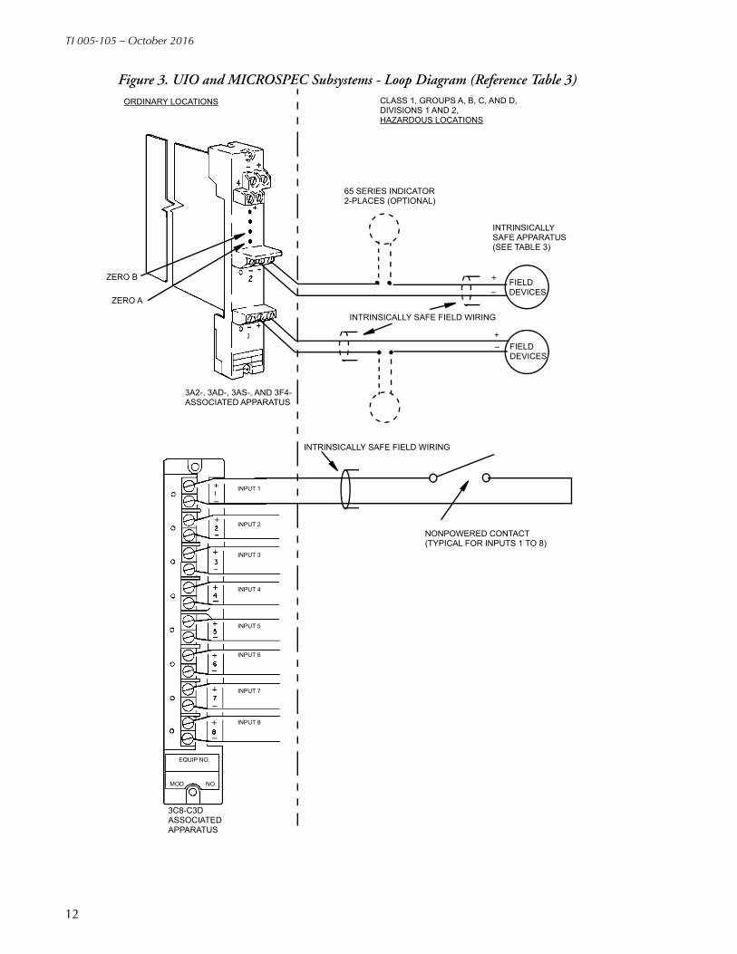
UFM SubsystemThe UFM input nest and the UFM cards listed in Table 5 are approved by CSA as providing intrinsically safe circuits to the field devices mounted in Class I, Groups A, B, C, and D, Divisions 1 and 2 hazardous locations. The slave nest (A2054KR) must be mounted in a nonhazardous location and must receive power via the DPX card. If any card in the nest is operating as intrinsically safe, then all cards in the nest must operate as intrinsically safe.
NOTENOTE: The current input card (3A8–I2D1) and voltage input card (3A8–V2D1) are not intrinsically safe and cannot be mounted in a nest containing intrinsically safe cards. This is because both cards must receive their power external from UFM, and there is no means to assure that this power source is intrinsically safe.
CLASS I, DIVISION 1,GROUPS A, B, C, AND D;CLASS II, DIVISION 1,GROUPS E, F, AND G;CLASS III, DIVISION 1LOCATIONS
ORDINARY LOCATIONS
I/A Series PRESSURE TRANSMITTER
HART -T
CSA CERTIFIEDASSOCIATEDAPPARATUS
+
–
HARTCOMMUNICATOR
UIO AND MICROSPEC SUBSYSTEMS ASSOCIATED APPARATUS
MODEL3A4-12DA-CGB3A3-12IA-CGB(TERMINAL GROUP 1)3AS-12IA-CGB(TERMINAL GROUP 2)
NOTES:
1. CONTROL ROOM EQUIPMENT SHALL NOT USE ORGENERATE MORE THAN 250 V.
2. OBSERVE ASSOCIATED APPARATUS (BARRIER) AND COMMUNICATION MANUFACTURER’S INSTRUCTIONS WHEN INSTALLING THIS EQUIPMENT.
3. INSTALL IN ACCORDANCE WITH CANADIAN ELECTRICALCODE (PART I).
14
TI 005-105 – October 2016
Figure 6. UFM Subsystem - Loop Diagram (Reference Table 5)
Table 5. UFM Subsystem Connected to Foxboro Intrinsically Safe Apparatus (See Figure 6)
Associated Apparatus UFM Subsystem Model
NumberField Wiring
Connection Criteria
Intrinsically Safe Apparatus Located in Class I, Groups A, B, C, and D, Divisions 1
and 2 Hazardous (Classified) Locations
3A8–M2D–CGB3A8–T2D–CGB
Input Circuit may connect to: Thermocouples
3A8–R2D–CGB Input Circuit may connect to: Resistance Temperature Detectors (RTDs)3D8–C2DL–CGB Input Circuit may connect to: Nonpowered Contacts
ORDINARY LOCATIONS CLASS 1, GROUPS A, B, C, AND D,DIVISIONS 1 AND 2HAZARDOUS LOCATIONS
TG1
THROUGH
TG8
3A8-R2D SERIESASSOCIATED APPARATUS
RTD (TYPICALOF 8-INPUTS)
THERMOCOUPLEOR NONPOWEREDCONTACTS(TYPICAL OF8-INPUTS)
+
–
+
–
–
+
–
3A8-M2D, 3A8-T2D,AND 3A8-C2D SERIESASSOCIATED APPARATUS
15

TI 005-105 – October 2016
Field Input/Output (FIO) SystemTable 6 and Table 7 list FIO system input/output cards that are approved by CSA as providing intrinsically safe circuits to the field devices mounted in Class I, Groups A, B, C, and D, Division 1 and 2 hazardous locations. The cards must be mounted in nest A2048BJ powered by DPXI card A2047VE, or mounted in satellite nest A2047WF powered by voltage monitor A2047WA.
Table 6. Field Input/Output (FIO) System Connected to Foxboro Intrinsically Safe Apparatus (See Figure 7 and Figure 8)
Foxboro Associated Apparatus FIO System
Field WiringConnection Criteria
Foxboro Intrinsically Safe Apparatus Located in Class I, Groups A, B, C, and D, Divisions 1 and 2
Hazardous (Classified) LocationsModel Number Rating
3F4–D2IA 24 V, 62 mA Output Circuit may connect to:
65 Series Indicators (a)E69 Series Converters and Positioners
a. 65 Series Indicator (65FS–CBJB, 65PH–JT, 65PV–JG, 65PV–JT or 65PV-JY) may be connected in loop with other intrinsically safe apparatus listed in the same segment of the table.
3F4–F2DA3F4–Q2DA
24 V, 69 mA24 V, 69 mA
Input Circuit may connect to:
E83 Series Vortex Flowmeters83 Series Vortex Flowmeter (b) (c)
b. To maintain intrinsic safety in 83 Series Vortex Flowmeters, current loop and pulse output field wiring pairs must be run in separate cables or with separate shields connected to intrinsically safe ground.
c. This Model also intrinsically safe for Class II, Groups E, F and G, Division 1; Class III, Division 1.
3F4–I2D1A 24 V, 62 mA Input Circuit may connect to:
Foxboro/ICT 27 Series Pressure Transmitters65 Series Indicators (one or two) (a)130 Series DMU transmitters820 Series Transmitters834DP Series Transmitters841, 843, and 847 Series Transmitters892 Series ConverterE83 Series Vortex Flowmeters83 Series Vortex Flowmeters (b) (c)870 Series Transmitters (d)I/A Series Pressure Transmitters (e)870IT Series Electrochemical Transmitters (d)
d. 870 Series Transmitters entity parameters based upon connection to 871 Series sensors. Maximum cable length of CSA certified 871EC or 871FT, 100 ft; 871PH, 500 ft.
e. Communications -I and -D only.
3F8–C2DCA Input Circuit may connect to:
Nonpowered Contacts
3F8–T2DA13F8–T2DA23F8–T2DA33F8–T2DA43F8–T2DA53F8–T2DA63F8–T2DA7
Input Circuit may connect to:
Thermocouples
3F8–R2DCA3F8–R2DNA3F8–R2DPA13F8–R2DPA23F8–R2DPA3
Input Circuit may connect to:
Resistance Temperature Detectors (RTDs)
16

TI 005-105 – October 2016
Figure 7. FIO System - Loop Diagram; RTD, Thermocouple, or Nonpowered Contact Inputs (Reference Table 6)
ORDINARY LOCATIONS CLASS 1, GROUPS A, B, C, AND D,DIVISIONS 1 AND 2HAZARDOUS LOCATIONS
TG1
THROUGH
TG8
3F8-R2D SERIESASSOCIATED APPARATUS
RTD (TYPICALOF 8-INPUTS)
THERMOCOUPLEOR NONPOWEREDCONTACTS(TYPICAL OF8-INPUTS)
+
–
+
–
–
+
–
3F8-T2DAND 3F8-C2D SERIES ASSOCIATEDAPPARATUS
17

TI 005-105 – October 2016
Figure 8. FIO System - Loop Diagram; Intrinsically Safe Apparatus Inputs (Reference Table 6)
ORDINARY LOCATIONS CLASS I, GROUPS A, B, C, AND D,DIVISIONS 1 AND 2HAZARDOUS LOCATIONS
+
0
–
+
0
–
FIELDDEVICES
INTRINSICALLYSAFE APPARATUS(SEE TABLE 6).
+
–
+
–
–
+
–
FIELDDEVICES
INTRINSICALLYSAFE APPARATUS(SEE TABLE 6).
3F4-D2IA AND 3F4-I2D1A SERIESASSOCIATED APPARATUS
TG1
THROUGH
TG4
3F4-F2D AND 3F4-Q2D SERIESASSOCIATED APPARATUS
18

TI 005-105 – October 2016
Figure 9. Typical Loop Diagram for Foxboro 3F8–D2ZA Connected to Telektron Intrinsically Safe Apparatus (Reference Table 7)
Table 7. Foxboro Associated Apparatus Connected to Other Manufacturer's Intrinsically Safe Apparatus (See Figure 9)
FoxboroAssociated Apparatus
FIO System Field WiringConnection
Criteria
Other Manufacturers’ Intrinsically Safe Apparatus Located in Class I, Groups A, B, C, and D,
Divisions 1 and 2 Hazardous (Classified) Locations
Model Number Rating Manufacturer Description
3F8–D2ZA3F8–D2WA
22 V, 56 mA24 V, 67.4 mA
Output Circuit may connect to:
Telektron Type P;RGS Electro-PneumaticsType EP100–A.
Solenoid Operator.Solenoid must be CSA approved as intrinsically safe.
ASCO Solenoid Driver
Table 8. TankExpert Hydrostatic Gauging and Inventory Management System (See Figure 10 and Figure 11)
Associated Apparatus TankExpert System
Field WiringConnection Criteria
Intrinsically Safe Apparatus Located in Class I, Groups A, B, C, and D, Division 1 Hazardous
(Classified) LocationsModel Number CS Code
880PFB–1880PFD–1
CS–E/CDB–ACS–E/CDB–A
Input Circuits may connect to:
880SGA SensorResistance Temperature Detector (RTD)
880PFB–2(a)880PFB–3(a)880PFD–2(a)880PFD–3(a)
CS–E/CNB–ACS–E/CNB–ACS–E/CNB–ACS–E/CNB–A
Input Circuits may connect to:
880SGA SensorResistance Temperature Detector (RTD)
CHANNEL
ORDINARY LOCATIONS HAZARDOUS LOCATIONS
TELEKTRONTYPE EP100-1ASOLENOIDOPERATOR, ORSIMILARDEVICE APPROVED BY CSA ASINTRINSICALLYSAFE.
FOXBORO EF8-D2ZAFIO ASSOCIATEDAPPARATUS
INTRINSICALLYSAFE FIELDWIRING
1
CHANNEL2
CHANNEL3
CHANNEL4
CHANNEL5
CHANNEL6
CHANNEL7
CHANNEL8
+
–
+–
+–
+–
+–
+–
+–
+–
+–
19

TI 005-105 – October 2016
Figure 10. TankExpert Hydrostatic Gauging and Inventory Management System (Division 1) – Loop Diagram (Reference Table 8)
NOTECAUTION: Refer to MI 020-057 and MI 020-070 for proper installation instructions for the 880PFB and 880PFD systems, respectively.
1
2
3
4
5
6
78
9
1011
12
1314
15
+
+
–
+
–
+
–
+
–
C
–
+
–
+
–
+
–
B
A
4 to 20 mA
CLASS I, GROUPS C AND D,DIVISION 1, HAZARDOUS LOCATIONS
CLASS 1, DIVISION 1, GROUPS A, B, C, AND D,
CLASS III,DIVISION 1, HAZARDOUS LOCATIONS
880SGASENSOR
CS CODECS-E/CB-A
TO 880 SGA SENSORCS CODE CS-E/CB-A
TO 880SGA SENSORCS CODE CS-E/CB-A
880PFB-1OR
880PFD-1TANK
CS CODECS-E/CDB A
FIBER OPTICCONNECTOR
PROCESSOR
880CFA HAND-HELD TERMINALWITH L0119CF OPTICALINTERFACE ASSEMBLY
RTD
CLASS II, DIVISION 1, GROUPS E, F, AND G,
20

TI 005-105 – October 2016
Figure 11. TankExpert Hydrostatic Gauging and Inventory Management System (Division 2) –Loop Diagram (Reference Table 8)
1
2
3
4
5
6
78
9
1011
12
1314
15
+
+
–
+
–
+
–
+
–
C
–
+
–
+
–
+
–
B
A
4 to 20 mA
CLASS I, DIVISION 2, GROUPS A, B, C, AND D,HAZARDOUS LOCATIONS
CLASS 1, DIVISION 1, GROUPS A, B, C, AND D,
CLASS III, DIVISION 1, HAZARDOUS LOCATIONS
880SGASENSOR
CS CODECS-E/CB-A
TO 880 SGA SENSORCS CODE CS-E/CB-A
TO 880SGA SENSORCS CODE CS-E/CB-A
880PFD-2OR
880PFD-3TANK
CS CODECS-E/CNB-A
FIBER OPTICCONNECTOR
PROCESSOR
880CFA HAND-HELD TERMINALWITH L0119CF OPTICALINTERFACE ASSEMBLY
RTD
CLASS II, DIVISION 1, GROUPS E, F, AND G,
21

TI 005-105 – October 2016
CSA Certified Zener BarriersThe instruments listed in Table 9 are approved for the hazardous (classified) locations listed when connected to CSA certified zener barriers having the ratings also listed in Table 9. Note the temperature class associated with each rating.
Table 9. Foxboro Intrinsically Safe Apparatus Connected to CSA Certified Zener Barriers (Other Manufacturer's Associated Apparatus)
CSA Certified ZenerBarriers Rated at:
Field WiringConnection
Criteria
FoxboroIntrinsically Safe Apparatus
V max R min
Temp.Class
FoxboroModel Number
Hazardous (Classified) Locations
33 V30 V28 V20 V
415 300 240 70
T4AT4AT4AT4A
Intrinsically Safe Field Wiring Terminals may connect to:
Foxboro/ICT 27 Series Pressure Transmitters821 Series Transmitters (a) (b) (c) (d)823DP Series Transmitters (b) (c) (d)823EP Series Transmitters (a) (c) (d)823MP Series Transmitters (a) (c) (d)827DF Series Transmitters (a) (c) (d)892 Series Converters1125 Pressure Transducers1150 Pressure TransducersE69F Series Converters (b)E69P Series ConvertersE83 Series Vortex Flowmeters (e)65 Series Indicators (f)83.-A Series Transmitters (e)
Class I, Groups A, B, C, and D, Division 1 locations.
33 V30 V28 V26.7 V20 V
415 300 240 200 70
T4AT4AT4AT4AT4A
Intrinsically Safe Field Wiring Terminals may connect to:
841AM and 841AX Series Transmitters841GM and 841GX Series Transmitters843DP DX EP EX MP MX Series Transmitters847DF DX EF EX Series Transmitters892 Series Converters65 Series Indicators (f)870 Series Transmitters (g)
Class I, Groups A, B, C, and D, Division 1 locations.
28 V
28 VDiode
28 V10 V
300
300 —
300 50
T3C
T3CReturn
T3CReturn
Intrinsically Safe Field Wiring Terminals may connect to:
130 Series DMU Transmitters820–D Series Transmitters (h)( (i)RTT10 Series Transmitters (h) (i)B0190AM Transmitters (h) (i) (j)860 Series Transmitters (d) (i)870IT Series ElectrochemicalTransmitters (g)
Class I, Groups A, B, C, and D, Division 1locations.
28 V
28 VDiode
300
300 —
T3C
T3CReturn
Intrinsically Safe Field Wiring Terminals may connect to:
83 Series Transmitters (e) (k) (l)I/A Series Pressure Transmitters (m)RTT20 Series Transmitters (h) (i) (l) (n)
Class I, Groups A, B, C, and D, Division 1locations.
28 VDiode
300 —
T3CReturn
Intrinsically Safe Field Wiring Terminals may connect to:
893 Series Transmitters Class I, Groups A, B, C, and D, Division 1 locations.
20 V 70 T3C Intrinsically Safe Field Wiring Terminals May Connect to:
834DP Series TransmittersE69R Series Converters
Class I, Group A, B, C, and D, Division 1 locations.
33 V28 V20 V
415 240 70
T3CT3CT3C
Intrinsically Safe Field Wiring Terminals may connect to:
RTT10 Series Transmitters (d)B0190AM Transmitters (d) (j)
Class I, Groups A, B, C, and D, Division 1 locations.
22

TI 005-105 – October 2016
33 V30 V28 V20 V
185 130 115 68
T4AT4AT4AT4A
Intrinsically Safe Field Wiring Terminals may connect to:
Foxboro/ICT 27 Series Pressure Transmitters821 Series Transmitters (a) (b) (c) (d)823DP Series Transmitters (b) (c) (d)823EP Series Transmitters (a) (c) (d)823MP Series Transmitters (a) (c) (d)827DF Series Transmitters (a) (c) (d)841AM and 841AX Series Transmitters841GM and 841GX Series Transmitters843DP DX EP EX MP MX Series Transmitters847DF DX EF EX Series Transmitters892 Series ConvertersE69F Series Converters (b)E69P Series Converters65 Series Indicators (f)870 Series Transmitters (g)83.-A Series Transmitters (e)
Class I, Groups C and D, Division 1 locations.
33 V30 V28 V20 V
185 130 115 68
T3CT3CT3CT3C
Intrinsically Safe Field Wiring Terminals may connect to:
RTT10 Series Transmitters (d)B0190AM Transmitters (d) (j)
Class I, Groups C and D, Division 1 locations.
30 V28 V20 V
130 115 68
T3CT3CT3C
Intrinsically Safe Field Wiring Terminals may connect to:
834DP Series TransmittersE69R Series ConvertersE83 Series Vortex Flowmeters (e)
Class I, Groups C and D, Division 1 locations.
33 V 185 T3A Intrinsically Safe Field Wiring Terminals may connect to:
E83 Series Vortex Flowmeters (e) Class I, Groups C and D, Division 1 locations.
a. With or without optional analog output indicator.b. 4 to 20 mA dc output signal only.c. Intelligent Transmitters with or without Model HHT Hand-Held Terminal (Configurator); (821AL–D, 821AM–D,
821GM–D, 821GH–D, 823DP–D, 823MP–D, 823EP–D, and 827DF–D).d. See Figure 12 for loop diagram showing 860, 8 -D, RTT10 or RTT20 Transmitter, Model HHT and CSA-
Certified Zener Barriers.e. See Figure 14 for the Integral and Remote Sensor Versions.f. 65 Series Indicator (65FS-CBJB, Temp. Code T4; 65PH-JT, 65PV-JG, 65PV-JT, or 65PV-JY, Temp. Code T6)
may be connected in a loop with other intrinsically safe apparatus listed in the same segment of the table.g. 870 Series Transmitters entity parameters based upon connection to 871 Series sensors. Maximum cable length
of CSA certified 871EC or 871FT, 100 ft; 871PH, 500 ft.h. With and without RDM10 Remote Digital Meters, with and without optional J0173KE Meter in 82 –D and a
Model HHT Hand-Held Terminal. A maximum of two meters shall be used in a loop.i. See Figure for loop diagram showing 860, 82 –D, RTT10 or RTT20 Transmitter, RDM10 Meter, Model HHT
Hand-Held Terminal, and CSA-Certified Zener Barrier.j. B0190AM Transmitter to be installed in suitable enclosure as acceptable to CSA.k. To maintain intrinsic safety in 83 Series Vortex Flowmeters, current loop and pulse output field wiring pairs must
be run in separate cables or with separate shields connected to intrinsically safe ground.l. This Model also intrinsically safe for Class II, Groups E, F and G, Division 1; Class III, Division 1.m. HART Communicator, Rosemount 275, can be connected to loop in hazardous or ordinary location are for HART
-T communications.n. RTT20 suitable for T6 @ 40°C, T4 @ 85°C ambient.
Table 9. Foxboro Intrinsically Safe Apparatus Connected to CSA Certified Zener Barriers (Other Manufacturer's Associated Apparatus) (Continued)
CSA Certified ZenerBarriers Rated at:
Field WiringConnection
Criteria
FoxboroIntrinsically Safe Apparatus
V max R min
Temp.Class
FoxboroModel Number
Hazardous (Classified) Locations
23
TI 005-105 – October 2016
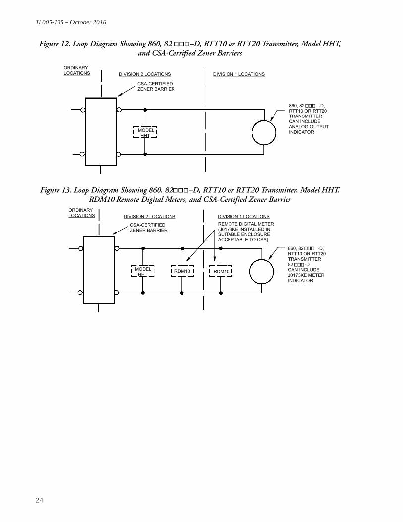
Figure 12. Loop Diagram Showing 860, 82 –D, RTT10 or RTT20 Transmitter, Model HHT, and CSA-Certified Zener Barriers
Figure 13. Loop Diagram Showing 860, 82–D, RTT10 or RTT20 Transmitter, Model HHT, RDM10 Remote Digital Meters, and CSA-Certified Zener Barrier
ORDINARYLOCATIONS DIVISION 2 LOCATIONS DIVISION 1 LOCATIONS
CSA-CERTIFIEDZENER BARRIER
MODELHHT
860, 82 -D,RTT10 OR RTT20TRANSMITTERCAN INCLUDEANALOG OUTPUTINDICATOR
860, 82 -D,RTT10 OR RTT20TRANSMITTER82 -DCAN INCLUDEJ0173KE METERINDICATOR
ORDINARYLOCATIONS DIVISION 2 LOCATIONS DIVISION 1 LOCATIONS
CSA-CERTIFIEDZENER BARRIER
MODELHHT
RDM10 RDM10
REMOTE DIGITAL METER(J0173KE INSTALLED INSUITABLE ENCLOSUREACCEPTABLE TO CSA)
24
TI 005-105 – October 2016
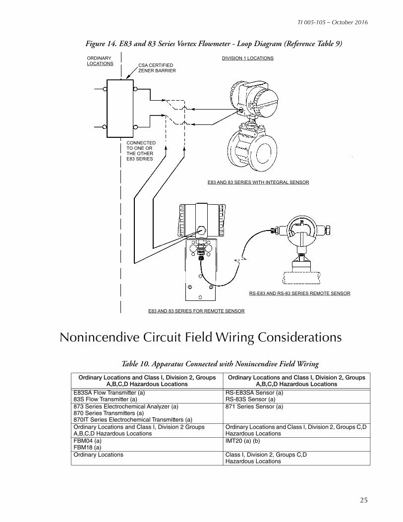
Figure 14. E83 and 83 Series Vortex Flowmeter - Loop Diagram (Reference Table 9)
Nonincendive Circuit Field Wiring Considerations
Table 10. Apparatus Connected with Nonincendive Field Wiring
Ordinary Locations and Class I, Division 2, Groups A,B,C,D Hazardous Locations
Ordinary Locations and Class I, Division 2, Groups A,B,C,D Hazardous Locations
E83SA Flow Transmitter (a)83S Flow Transmitter (a)
RS-E83SA Sensor (a)RS-83S Sensor (a)
873 Series Electrochemical Analyzer (a)870 Series Transmitters (a)870IT Series Electrochemical Transmitters (a)
871 Series Sensor (a)
Ordinary Locations and Class I, Division 2 Groups A,B,C,D Hazardous Locations
Ordinary Locations and Class I, Division 2, Groups C,D Hazardous Locations
FBM04 (a)FBM18 (a)
IMT20 (a) (b)
Ordinary Locations Class I, Division 2, Groups C,D Hazardous Locations
ORDINARYLOCATIONS CSA CERTIFIED
ZENER BARRIER
DIVISION 1 LOCATIONS
CONNECTED TO ONE ORTHE OTHERE83 SERIES
E83 AND 83 SERIES WITH INTEGRAL SENSOR
RS-E83 AND RS-83 SERIES REMOTE SENSOR
E83 AND 83 SERIES FOR REMOTE SENSOR
25
TI 005-105 – October 2016
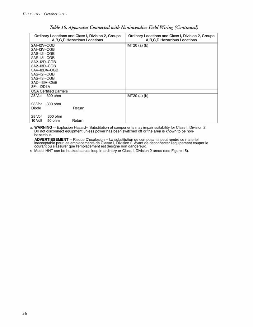
2AI–I2V–CGB2AI–I3V–CGB2AS–I2I–CGB2AS–I3I–CGB3A2–I2D–CGB3A2–I3D–CGB3A4–I2DA–CGB3AS–I2I–CGB3AS–I3I–CGB3AD–I3IA–CGB3F4–I2D1A
IMT20 (a) (b)
CSA Certified Barriers28 Volt 300 ohm
28 Volt 300 ohmDiode Return
28 Volt 300 ohm10 Volt 50 ohm Return
IMT20 (a) (b)
a. WARNING -- Explosion Hazard-- Substitution of components may impair suitability for Class I, Division 2. Do not disconnect equipment unless power has been switched off or the area is known to be non-hazardous.
ADVERTISSEMENT -- Risque D'explosion -- La substitution de composants peut rendre ce materiel inacceptable pour les emplacements de Classe I, Division 2. Avant de deconnecter l'equipement couper le courant ou s'assurer que l'emplacement est designe non dangereux.
b. Model HHT can be hooked across loop in ordinary or Class I, Division 2 areas (see Figure 15).
Table 10. Apparatus Connected with Nonincendive Field Wiring (Continued)
Ordinary Locations and Class I, Division 2, Groups A,B,C,D Hazardous Locations
Ordinary Locations and Class I, Division 2, Groups A,B,C,D Hazardous Locations
26

TI 005-105 – October 2016
Figure 15. IMT20 Series Transmitter - Loop Diagram (Reference Table 10)
MODELHHT
MODELHHT
MODELHHT
SPEC 200OR
SPECTRUMSYSTEM
8000,8000A,8300
FLOWTUBE
IMT20TRANSMITTER
IMT20TRANSMITTER
IMT20TRANSMITTER
8000,8000A,8300
FLOWTUBE
8000,8000A,8300
FLOWTUBE
FBM04/FBM18
DIVISION 2 LOCATIONS
DIVISION 2 LOCATIONS
DIVISION 2 LOCATIONS
ORDINARYLOCATIONS
ORDINARYLOCATIONS
ORDINARYLOCATIONS
I/A SerieSSYSTEM
CSA-CERTIFIED ZENER BARRIER
4 - 20 mA dc
4 - 20 mA dc
4 - 20 mA dc
27

TI 005-105 – October 2016
I/A Series System Mass Flowmeter Wiring for Division 2 Locations
Figure 16. CNN Loop Diagram
I/A Series System FBMs with CSA Certified I/O CircuitsThe Canadian Electrical Code allows nonincendive circuits for use in Class I, Division 2, hazardous locations. CSA does not allow the use of the “entity parameter” concept for field apparatus except for non-energy generating or storing devices such as RTDs, thermocouples, switches and the associated interconnecting wiring. Following are the FBMs that currently have CSA certified I/O circuits:
NOTEFor the Fieldbus Isolator module, the values of Ca and La are satisfied when Foxboro-specified twinaxial cable (P/N P0170GG or P0170GF) is used to interconnect two Fieldbus Isolator modules. This cable has sufficient inherent series resistance to offset its internal inductance and capacitance at any length.
Table 11. FBMs with CSA Certified I/O Circuits
FBM Type Voc Isc Ca La
Fieldbus Isolator 5.0 V dc 0.5 A 1000 F 0.2 mH
FBM02 1.0 V dc 1.0 mA 1000 F 1000 mH
FBM03 6.0 V dc 1.0 mA 1000 F 1000 mH
FBM33 6.0 V dc 1.0 mA 1000 F 1000 mH
Class I, Div. 2, Groups A, B, C, DHazardous Locations
Non-Hazardous Locations
TRANSMITTER
CFT15
FLOWTUBECFS10 OR
CONDUIT OR OTHERCODE APPROVEDDIV. 2 WIRINGMETHOD
CUSTOMER-SUPPLIED POWER:100 - 120 V ac220 - 240 V ac24 - 42 V dc
ALARM, FREQUENCY, 4 - 20 mA,RS-485, AND HHT CIRCUITS
CFS20
NONINCENDIVE
-RTD-DRIVERS-SENSORS
FLOWTUBE CKTS
28

TI 005-105 – October 2016
29

TI 005-105 – October 2016
Invensys Systems, Inc.38 Neponset AvenueFoxboro, MA 02035United States of Americahttp://www.schneider-electric.com
Global Customer SupportInside U.S.: 1-866-746-6477Outside U.S.: 1-508-549-2424Website: http://support.ips.invensys.com
Copyright 1985-2016 Invensys Systems, Inc.All rights reserved.
Invensys, Foxboro, I/A Series, MICROSPEC, SPEC 200, TankExpert, and UFM are trademarks of Invensys Limited, its subsidiaries, and affiliates. All other trademarks are the property of their respective owners.
Invensys is now part of Schneider Electric.
1016


