
Targeted Application of STATCOM Technology in the Distribution Zone
Christopher J. LeeSenior Power Controls Design Engineer
Electrical Distribution Division
Mitsubishi Electric Power Products
Electric Power Industry Conference/University of Pittsburgh
MITSUBISHI ELECTRIC POWER PRODUCTS, INC. 1

Outline
• Overview of Relevant Grid Compensation Areas and Technology
• Application of STATCOM in IEEE 34 Node Distribution Feeder
• Application of using Distributed STATCOMs in a Residential Feeder
• Advantages of Cascaded H-bridge vs Smart Inverter
MITSUBISHI ELECTRIC POWER PRODUCTS, INC. 2

3 “Zones” of Delivery
MITSUBISHI ELECTRIC POWER PRODUCTS, INC. 3
Zone Line Voltage Description
Transmission 69kV - above High power transmission prior to primary step down transformer
Distribution 4.76kV -69kV Portion from secondary of stepdown transformer to service transformers
Grid Edge 4.76kV -below Area of grid after step down transformers to home/consumers. Referring to pole mount service distribution
100V 1kV 10kV 100kV 1MV
10kVA
100kVA
1MVA
10MVA
100MVA
1GVA
Distribution Zone
Grid Edge
Transmission Zone
Line Voltage
Typ
ical
Lin
e/F
eed
er
Pow
er

Current Power Quality Solutions
4
Simplified Power System One Line
Broken into 3 main zones for power quality management
1) Centralized Solution (Transmission Zone)
• STATCOM/SVC/Shunt Capacitor/Reactor solutions
• STATCOM closely coupled to Generator performance
• Voltage Support/Fault Recovery/Reactive Power Support
• Zone Overview– High Voltage/High Power between Generator/Step Up, and Step down
transformer
– Minimal nodes and branches
2) Distributed Solution (Distribution Zone)
• High concentration of voltage regulators, capacitor banks
• Minimal STATCOM products
• Zone Overview– High concentration area of distributed energy resources (DER)
– Large number of nodes
3) Distributed Solution (Grid Edge)
• Zone Overview– Area after service transformers
– 3 Phase, but often separated into 1 or 2 phases with unequal loading on each phase
– Highest number of nodes
• Low power pole mount solutions– Peak Demand Management
– Voltage Conservation
MITSUBISHI ELECTRIC POWER PRODUCTS, INC.
Clip Art Source: PowerPoint

Centralized and Edge Solutions
Centralized• Centralized solution applied at
transmission side, typically single STATCOM/SVC for entire transmission line
• Power Flow Support
• Generator Support
• Steady state instability issues
• Over voltage issues
• Utility scale installation and cost
• Large undertaking due to space and regulation requirements
• Slower response due to magnitude of equipment power
MITSUBISHI ELECTRIC POWER PRODUCTS, INC. 5
Distributed Solution At the Grid Edge• Typically Pole Mounted
• Single or Two Phase Solution
• Low power servicing a few loads, requiring high numbers for substantial impact
• Power Factor Control
• Volt/Var Optimization(VVO) (Typically 25kvar or less)
• Fast response for voltage stability
• Peak demand management
• Conservation Voltage Reduction (CVR)
• May delay conductoring 2-3 years
• Not for use in distributed generation voltage stability
High Power Zone
High Power Solution
Low Power Zone
Low Power Solution
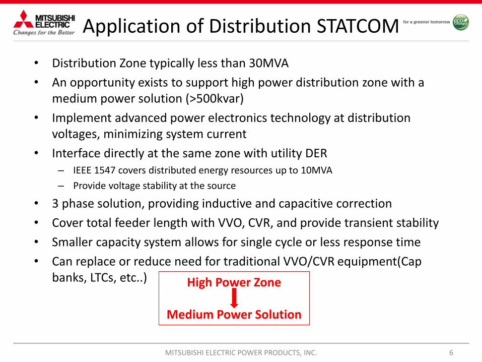
Application of Distribution STATCOM
• Distribution Zone typically less than 30MVA
• An opportunity exists to support high power distribution zone with a medium power solution (>500kvar)
• Implement advanced power electronics technology at distribution voltages, minimizing system current
• Interface directly at the same zone with utility DER– IEEE 1547 covers distributed energy resources up to 10MVA
– Provide voltage stability at the source
• 3 phase solution, providing inductive and capacitive correction
• Cover total feeder length with VVO, CVR, and provide transient stability
• Smaller capacity system allows for single cycle or less response time
• Can replace or reduce need for traditional VVO/CVR equipment(Cap banks, LTCs, etc..)
MITSUBISHI ELECTRIC POWER PRODUCTS, INC. 6
High Power Zone
Medium Power Solution

IEEE 34 Feeder Study
• IEEE 34 node sample feeder study performed by MEPPI PSES
• Investigation of STATCOM operability at distribution level using medium sized building blocks in typical higher power feeder location
• 2.5 MVA substation with nominal operating voltage of 24.9kV
• 36 Mile feeder length
• Current traditional compensation techniques– Two in-line voltage regulators required to maintain acceptable voltage profile.
– Two shunt capacitors are used to maintain an acceptable range for voltage profile
• Line Characteristics– An in-line transformer reduces the voltage to 4.16 kV for a short section of the feeder.
– Unbalanced loading with both “spot” and “distributed” loads. Distributed loads are assumed to be connected at the center of the line segment.
MITSUBISHI ELECTRIC POWER PRODUCTS, INC. 7

IEEE Feeder Study
MITSUBISHI ELECTRIC POWER PRODUCTS, INC. 8
Sample Circuit -Published IEEE 34 Node Radial Distribution feeder based on data from test feeder in Arizona

IEEE 34 Distribution Voltage Profile
9
• The voltage profile of a distribution feeder decreases as it extends away from the substation.
• Traditional voltage compensation techniques do not account for voltage increases along the feeder
• Low load conditions will result in voltages near the maximum acceptable range close to voltage
regulation equipment
• The use of DERs will result in the voltage at the point of common coupling to rise and exceed the
maximum voltage range.
• Dynamic reactive devices provide voltage support for feeder operation at various loading conditions
to prevent voltage violations.
Base Case Traditional Methods
* Shunt Capacitor and Voltage Regulators
MITSUBISHI ELECTRIC POWER PRODUCTS, INC.

IEEE 34 Distribution Voltage Profile
Shunt Capacitor Solution
MITSUBISHI ELECTRIC POWER PRODUCTS, INC. 10
STATCOM Solution

11
Four total
STATCOMs (two at
each location)
Under voltage
limit 0.95 p.u.
Over voltage
limit 1.05 p.u.
Using STATCOMs exclusively improves the voltage profile of the
distribution feeder. Note that the scheduled voltage at the substation is 1.05
p.u. As the distance increases, voltages along the nodes in the test feeder
decreases, and slopes down near 0.95 p.u. at 35 miles.
Voltage profile with
shunt capacitor replaced
by STATCOMs of same
size at the same location
(non-optimal locations).
Voltage profile with
regulators and shunt
capacitors
Voltage profile with shunt
capacitor replaced by
STATCOMs of same size at
optimal locations.
Under voltage
limit 0.95 p.u.
Over voltage limit
1.05 p.u.
Locating STATCOMs at optimal sites removes the need of shunt capacitors and
drives the voltage to within an acceptable voltage profile.
• For new feeders, or the expansion of existing feeders, optimally located STATCOMs can be effectively
used to improve the voltage profile and regulate the voltage according to user-defined levels.
• STATCOMs can be used in conjunction with existing voltage regulators and capacitor banks to improve
the voltage profile on existing distribution feeders.
Distribution STATCOMs Lightly Loaded Feeder: STATCOMs + Traditional Methods
IEEE 34 Distribution Voltage Profile
MITSUBISHI ELECTRIC POWER PRODUCTS, INC.

Residential Feeder Studies
• Several studies performed on residential distribution feeders
• Simplified model representing studies of consumer 120V feed
• Evaluated with respect to ANSI C84.1-2006– Max Voltage before Violation-125V
• Average Model Properties
– ~25MVA
– Total conductor length - 60 Miles
– Maximum distance from substation - 12 Miles
– Available DER - 5MW Solar
– Reactive devices - 4x 400 kvar Capacitor Banks
MITSUBISHI ELECTRIC POWER PRODUCTS, INC. 12

Base Feeder Study
• Normal load
• Solar generation -OFF
• Capacitor banks -OFF
• STATCOM-OFF
MITSUBISHI ELECTRIC POWER PRODUCTS, INC. 13
120-123V123-125V
Base feeder conditions show elevated voltage conditions close to the substation
38%
62%
Base Feeder Results
120-123V 123-126V

Res. Feeder Online Shunt Capacitors
MITSUBISHI ELECTRIC POWER PRODUCTS, INC. 14
Several branches with high voltage violations occur near capacitor banks
120-123V123-125V126-127V127-130V
21%
62%
14%
3%
Shunt Capacitors On
120-123V 123-125V 125-127V 127-130 V
Capacitor
• Normal load
• Solar generation -OFF
• Capacitor banks -ON– 4x 400kvar
• STATCOM-OFF

Res. Feeder ±2.5Mvar STATCOM
• All voltage violations resolved with centrally located STATCOM
MITSUBISHI ELECTRIC POWER PRODUCTS, INC. 15
120-123V123-125V126-127V127-130V
100%
2.5 Mvar STATCOM
120-123V
STATCOM
• Normal load
• Solar generation -OFF
• Capacitor banks -OFF
• STATCOM-ON– 2.5 Mvar STATCOM

Res. Feeder with 5MW Solar
Large portion of feeder in violation due to excess generation PV installation. Small area
of voltage violations in excess of 130V
MITSUBISHI ELECTRIC POWER PRODUCTS, INC. 16
120-126V126-128V128-130V130-132V
80%
10%
4%6%
5 MW Solar
120-126V 126-128V 128-130V 130-132V
PV Installation
• Normal load
• Solar generation – ON– 5 MW Solar
• Capacitor banks - OFF
• STATCOM - OFF

Res. Feeder with 5MW Solar ±2.5 Mvar STATCOM
MITSUBISHI ELECTRIC POWER PRODUCTS, INC. 17
All violations resolved with centrally located STATCOM
120-126V126-128V128-130V130-132V
100%
2.5 Mvar STATCOM
120-123V
STATCOM
PV Installation
• Normal load• Solar generation – ON
– 5 MW Solar
• Capacitor banks - OFF• STATCOM – ON
– ±2.5 Mvar STATCOM

Res. Feeder with 5MW Solar ±500 kvar STATCOM
MITSUBISHI ELECTRIC POWER PRODUCTS, INC. 18
Medium sized STATCOM resulted in 25% decrease in violation. All voltage violations above 130V resolved
120-126V126-128V128-130V130-132V
86%
10%
4%0%
500KVar STATCOM
120-126V 126-128V 128-130V 130-132V
STATCOM
PV Installation
• Normal load• Solar generation – ON
– 5 MW Solar
• Capacitor banks - OFF• STATCOM – ON
– 4x ±500 kvar STATCOM

Res. Feeder with 5MW Solar 4x ±500 kvar STATCOM
MITSUBISHI ELECTRIC POWER PRODUCTS, INC. 19
All violations resolved with distributed STATCOM solution
120-126V126-128V128-130V130-132V
100%
4x 500KVar STATCOM
120-126V
STATCOM
PV Installation
• Normal load• Solar generation – ON
– 5 MW Solar
• Capacitor banks - OFF• STATCOM – ON
– ±500 kvar STATCOM

Res. Feeder Study Conclusions
MITSUBISHI ELECTRIC POWER PRODUCTS, INC. 20
• STATCOM application in 25MVA Feeder showed significant improvement
• Single 2.5Mvar STATCOM was solve voltage issues due to existing equipment and issues to presence of DER
• Single 500kvar STATCOM was able to improve power quality by 25%
• 4 optimally place 500Kvar STATCOMs was able to equal the performance of a single 2.5Mvar solution
• Use of smaller STATCOM size support future feeder growth without increasing size of central STATCOM
• More studies on other distribution grids will need to be performed, but shows promise of further positive results

STATCOM Topology Comparison
MULTILEVEL INVERTER (STATCOM)
MITSUBISHI ELECTRIC POWER PRODUCTS, INC 21
A smart inverter cannot equal the performance features of a STATCOM
TYPICAL “SMART” INVERTER

STATCOM Topology Comparison
MULTILEVEL CONVERTER (STATCOM)Cascaded H-Bridge topology
Reactive power absorption & injection
• Distributed DC bus
• Low harmonic content due to multiple levels
• Limited or no filters required (limited resonance issues with grid)
• Low voltage stress on FWD & IGBT’s
• IGBT, Diode, & cap redundancy
• More overall switching devices
• IGBT matching is not required (lower spare parts cost)
• Faster reaction time to charge / discharge capacitors
• Easier to achieve higher voltage level using common building block
Typical SMART INVERTERNPC or Flying Capacitor topology
• Reactive power absorption & injection
• Common DC bus
• High harmonic content due to minimum switching levels
• Large inductor / cap filters required (possible resonance issues with grid)
• High voltage stress on FWD & IGBT’S
• Limited redundancy (IGBT & diodes)
• Less overall switching devices
• Matched IGBT’s for voltages > 3kV (higher spare parts cost)
• Slower reaction times to charge larger capacitors
• Higher voltages require placing low voltage devices in series or using higher voltage rated device
MITSUBISHI ELECTRIC POWER PRODUCTS, INC 22
MMC Inverter more suited for STATCOM Technology

Inverter Comparison
Cascaded H-Bridge
Application in Delta Configuration
• Easier fault handling of single phase to ground faults
• Easier unbalanced operation characteristics
• Easier negative sequence control
• Lower current means results in lower conduction loss
MITSUBISHI ELECTRIC POWER PRODUCTS, INC. 23
Summary
Distributed Solution for a Distribution Problem
• Distribution zone has not been traditionally targeted with advanced technology for power quality management
• High penetration of DERs in distribution zone provide the opportunity to stabilize the system near the source
• The implementation of medium powered STATCOMs in the distribution feeder shows they significantly affect power quality
• STATCOM technology in the distribution zone provides inductive and capacitive operation, allowing for full range of voltage support
• By decentralizing a single STATCOM and installing throughout the feeder shows significant improvement at the consumer load
• Allows for application of latest low voltage power electronics technology at higher voltage zone
MITSUBISHI ELECTRIC POWER PRODUCTS, INC. 24

MITSUBISHI ELECTRIC POWER PRODUCTS, INC. 25
Thank you for your attentionQuestions?


